A Lester Dent Bibliography · Lester Dent A LESTER DENT BIBLIOGRAPHY by Will Murray
date post
21-Dec-2015Category
view
230download
0
Basic Concepts of Other Basic Concepts of Other Imaging ModalitiesImaging Modalities
Dent 5101

Body-section RadiographyBody-section Radiography
• A special radiographic technique that blurs out the shadows of superimposed structures
• Object of interest less blurred• Does not improve the sharpness

Tube and Film Move in Opposite Tube and Film Move in Opposite DirectionDirection

• Tube and film move in opposite direction, and rotate about a fulcrum
• The level of the fulcrum is the focal plain

BlurringBlurring
• Determined by:– Distance of the tube travel– Distance from the focal plain– Distance from the film– Orientation of tube travel

Panoramic RadiographyPanoramic Radiography
Panoramic RadiographyPanoramic Radiography
• Obtained by rotating a narrow beam of radiation in the horizontal plane
• The film is rotated in the opposite direction while the object (jaws) is stationary


Focal TroughFocal Trough
• A 3-dimensional curved zone or image layer in which structures are reasonably well defined.

Types of Panoramic Types of Panoramic MachinesMachines• Panorex – Two centers of rotation.
Interruption of exposure in the midline
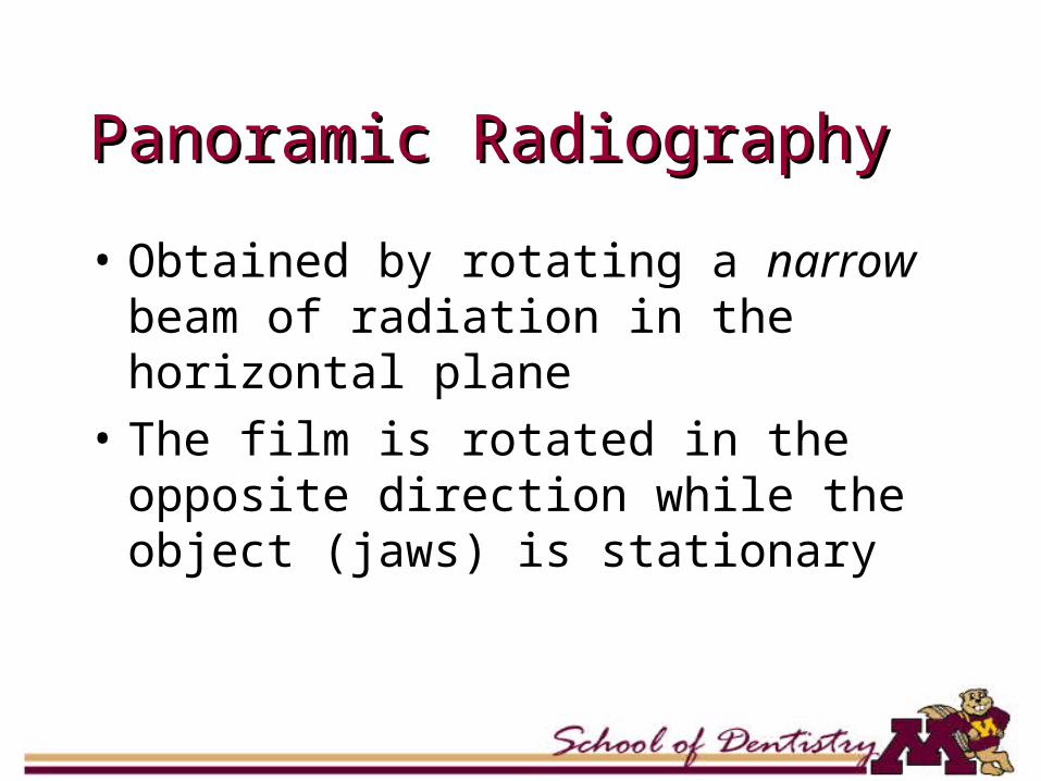
• Orthopantomogram – Three centers of rotation. Continuous image

Panorex ImagePanorex Image
OrthopantpmographOrthopantpmograph


Image IntensificationImage Intensification

Early FluoroscopyEarly Fluoroscopy
• Early fluoroscopy done by direct observation
• Screen was poorly illuminated - image perception inadequate

Image Intensification Image Intensification
• Image intensifier improved viewing of fluoroscopy

Intensifier TubeIntensifier Tube• Four parts:
– Input phosphor and photocathode
– Electrostatic focusing lens
– Accelerating anode
– Output phosphor

Intensifier Tube (Cont.)Intensifier Tube (Cont.)• Input phosphor: cesium iodide (CsI) or
zinc-cadmium-sulfide.• Photocathode: A photo-emissive metal.• Electrostatic focusing lens: series of
negatively charged electrodes—focuses the electron beam.
• Output phosphor: Provides thousand-fold more light photons.

Intensifier TubeIntensifier Tube
• Used in:– Sialography– Arthrography

Computed TomographyComputed Tomography

Computed TomographyComputed Tomography
• Introduced in 70’s• Principle: Internal structures of an
object can be reconstructed from multiple projections of the object

Philips CTVision Philips CTVision SecuraSecura

Mechanism of CTMechanism of CT
• X-ray tube is rotated around the patient
• Radiation transmitted through the patient is absorbed by a ring of detectors
• Absorbed radiation is converted to an image
Detectors
DetectorsDetectors
• Scintillation crystals• Xenon-gas ionization chamber

Scintillation CrystalsScintillation Crystals
• Materials that produce light (scintillate) when x-rays interact
• Similar to intensifying screen• Number of light photons produced
energy ofincident x-ray beam• Light photons need to be
converted to electrical signal

Ionization ChamberIonization Chamber
• X-ray ionizes xenon gas
• Electrons move towards anode
• Generates small current
• Converted to electrical signal

AttenuationAttenuation
• Reduction in the intensity of an x-ray beam as it traverses matter, by either the absorption or deflection of photons from the beam

Pixel - VoxelPixel - Voxel
• Pixel - picture element
• Voxel - volume element

CT NumberCT Number
Typical CT values
Tissues Range (Hounsfield unit)
Air -1000
Lung -200 to –500
Fat -50 to –200
Water 0
Muscle +25 to +45
Bone +200 to +1000

Image Display: WindowingImage Display: Windowing
• Usual CRT can display ~256 gray levels
• 2000 CT numbers• Select the CT
number of the tissue of interest, then range of ±128 shades

Cone Beam CTCone Beam CT
• Uses cone shaped x-ray beam.
• Beam scans the head in 360 degrees.
• Raw data are reformatted to make images


Benefits of Cone Beam Benefits of Cone Beam ImagingImaging
• Less radiation than multi-detector CT due to focused X-rays (less scatter)
• Fast and comfortable for the patient (9 to 60s)
• Procedure specific to head and neck applications
• One scan yields multiple 2D and 3D images
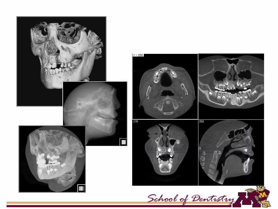
Anatomic Landmarks on Anatomic Landmarks on CTCT


Axial CT SectionsAxial CT Sections


1. Zygomatic Arch2. Lat. Pterygoid plate3. Optic canal4. Sphenoid sinus5. Soft tissues of
nasopharynx
Coronal Coronal SectionsSections

1. Frontal bone (orbital plate)
2. Ethmoid air cells3. Middle concha4. Maxillary sinus5. Inferior concha

1. Vomer2. Ramus3. Follicle of molar4. Gr. wing of
Sphenoid5. Tongue6. Mylohyoid m

Magnetic Resonance Magnetic Resonance ImagingImaging

Magnetic Resonance Magnetic Resonance ImagingImaging• Three steps of MRI• MRR
– Magnetic Field– Radio-frequency Pulse– Relaxation

Magnetic Moment Magnetic Moment DirectionDirection

Application of RF PulseApplication of RF Pulse
Relaxation

Spin or Angular MomentSpin or Angular Moment
• 1H, 14N, 31P, 13C, and 23Na has nuclear spin
• They spin around their axes similar to earth spinning around its axis
• Elements with nuclear spin has odd number of protons, neutrons

Magnetic MomentMagnetic Moment
• When a nucleus spins, it has angular momentum
• When the spinning nucleus has a charge, it has magnetic dipole moment
• Moving charges produce magnetic fields

Hydrogen NucleusHydrogen Nucleus
• Most abundant• Yields strongest MR signal

Radiofrequency PulseRadiofrequency Pulse
• RF pulse is an electromagnetic wave
• Caused by a brief application of an alternating electric current

Receiver CoilsReceiver Coils
• Send or “broadcast” the RF pulse• Receive or “pick up” the MR
signals• Types: Body coils, head coils, and
a variety of surface coils

Philips Gyroscan InteraPhilips Gyroscan Intera

RelaxationRelaxation
• This is the process that occurs after terminating the RF pulse
• The physical changes caused by the RF pulse revert back to original state
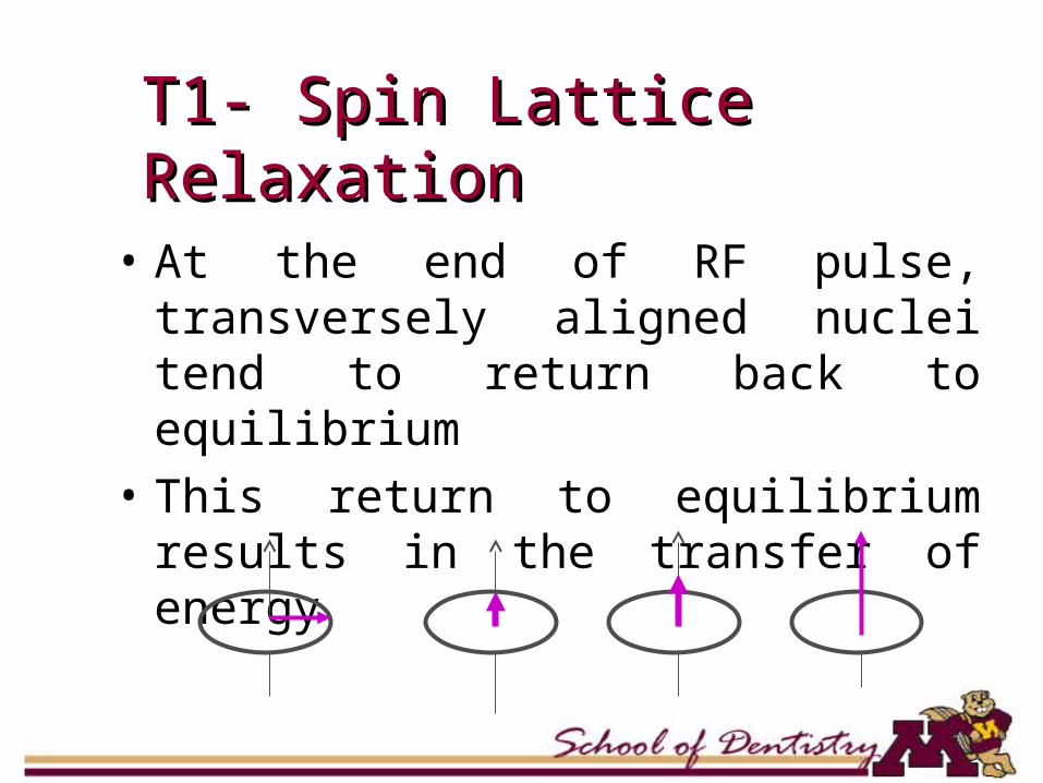
T1- Spin Lattice RelaxationT1- Spin Lattice Relaxation
• At the end of RF pulse, transversely aligned nuclei tend to return back to equilibrium
• This return to equilibrium results in the transfer of energy

T2- Spin-spin RelaxationT2- Spin-spin Relaxation
• While the nuclei are in transverse phase, their magnetization interfere with each other.
• This interference leads to the loss of transverse magnetization.

Magnetic Field StrengthsMagnetic Field Strengths
• Measured in Tesla or Gauss• Usual MRI field strength ranges
from 0.5 to 2.0 Tesla• Earth’s magnetic field is about
0.00005 Tesla (0.5 Gauss)

Advantages of MRIAdvantages of MRI
• Higher resolution of tissues• No ionizing radiation• Multiplanar imaging

Disadvantages of MRIDisadvantages of MRI
• Long imaging time• Hazards with ferromagnetic metals
(pacemakers, vascular clips, etc)• Claustrophobia• Higher cost

Relative Brightness of Relative Brightness of TissuesTissuesFat WhiteMarrowBrainMuscle GrayBody FluidTMJ DiskCortical BoneAir Black


Nuclear MedicineNuclear Medicine

Nuclear MedicineNuclear Medicine
• Radioactive compounds• Target tissues• Radioactive agents pools in
the target tissues• Detected and imaged by
external detectors (gamma camera).

Nuclear MedicineNuclear Medicine
• Shows structure and function of the target tissues
• Static and dynamic conditions• Scintigraphy scans or RN
(radionuclide) scans• Bone scans or salivary gland
scans
TechnetiumTechnetium
• 99mTcO4- - thyroid and salivary
gland scan • 99Tc phosphate - bone scan

• Is this an active disease?


Phases of Salivary Gland Phases of Salivary Gland ScanScan
• Flow phase:– Five to 10 mCi of 99mTcO4
– first 30 to 120 seconds – shows flow of blood
• Concentration phase:– next 30 to 45 minutes– demonstrate the anatomy and function
• Washout Phase:– administer sialagogue– demonstrates secretory capabilities

Cephalometric Cephalometric RadiographyRadiography• Reproducible and standardized
views• For measurements and assess
growth• Fixed source to film distance – 60
inches• Cephalostats and earplugs help in
reproducible positions

Cephalometric Cephalometric Radiography Radiography
Contrast AgentsContrast Agents

Contrast AgentsContrast Agents
• Radiopaque materials• Water soluble• Fat soluble• 28 – 38% iodine

Phases of SialographyPhases of Sialography
• Ductal• Acinar• Evacuation
Indications of SialographyIndications of Sialography
• Acute swelling secondary to ductal obstruction
• Recurrent Inflammation• Palpable salivary gland mass• Autoimmune Sialadenitis

Contraindications of Contraindications of SialographySialography• Sensitivity to contrast agents• Acute Sialadenitis• Limited use in tumor diagnosis


Scintigraphy SialographyRadioactive material Radiopaque
material
Through blood stream
Through duct
All glands imaged at the same time
One gland at a time
Imaged by gamma camera
Imaged by fluoroscopy

Contrast Studies: Contrast Studies: ArthrographyArthrography
ArthrographyArthrography
• Contrast media is introduced in joint spaces
• Upper vs. lower joint space• Viewed by Image Intensifier
Fluoroscopy• Video recording allows study of joint
movement
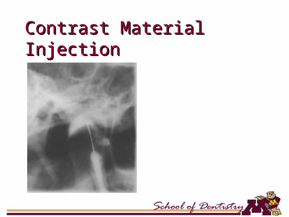
Contrast Material InjectionContrast Material Injection

Open PositionOpen Position
• Translation of condyle
• Reduction of disk