Basic Aspects of C7-ack Growth and Fracture · NRL Report 6598 Basic Aspects of C7-ack Growth and...
78
NRL Report 6598 Basic Aspects of C7-ack Growth and Fracture Novemfber 21, 1 967 1OF~ NAVAL RESEARCH LABORATORY Washington, D.C. 0-
Transcript of Basic Aspects of C7-ack Growth and Fracture · NRL Report 6598 Basic Aspects of C7-ack Growth and...
NRL Report 6598
Basic Aspects of C7-ack Growth and Fracture
Novemfber 21, 1 967
1OF~
NAVAL RESEARCH LABORATORY
Washington, D.C.
0-

NRL Report 6598
Basic Aspects of Crack Growth and Fracture
G. R. IRWIN AND J. M. KRAFFT
Mechanics Divi.sion
P'. C. PARIS
Lehigh UniversityBethlehem, Pennsylvania
and
A. A. WELLS
Queens UniversityBelfast, North Ireland
November 21, 1967
NAVAL RESEARCH LABORATORYWashington, D.C.
This document has been approved for public release and sale; its distribution is unlimited.

Preceding Page Blank
CONTENTS
AbstractProblem Status iiAuthorization ii
GENERAL COMMENTS ON DEFECTS AND FRACTURE CONTROL 1
LINEAR-ELASTIC MODELING OF CRACKS 6
Progressive Crack Extension 6Linear Crack Stress Field Analysis 7Experimental Fracture Mechanics Analysis 11
PLASTICITY ANALYSIS CONCE PTS FOR CRACKS 12
The r. Plasticity Adjustment Factor 13The Strip-Yield Zone Concept 14The Mode III Elastic-Plastic Treatment 15Fracture Characterization Problems in Relation to Plastic Analysis 17
SLOW-STABLE CRACK GROWTH 18
Crack Growth Rates With Fatigue 18Crack Growth Rates With Environmen.t 24
CRACK PROPAGATION AND FRACTURE TOUGHNESS 25
Measurements of K, and ,,. for Very-High-Strength Metals 25The Brittle-Ductile Fracture Transition 27Double Cantilever and Face-Grooved Specimens 29General Aspects of Dynamic Crack Stress Field Analysis 31.The Fracture Process Zone, Time Rate Effects, and Minimum
Fracture Toughness 32Fracture Toughness in Relation to Plastic Flow Properties 36Dynamic Fracture Toughness Measurements and Fracture
Transition-Temperature 'Tests 38Comments on Crack Opening Dislocation Measurements 44Comments on Load Toughening and Strain Aging 44
FRACTURE CONTP.OL PLANS 46
Comments on Elimination and Slow Growth of Defects 46Fracture Safety in Relation to Crack Arrest 47The Relationship of Fracture Toughness to Pressure-Vessel Design
Load in Terms of a Leak-Before-Break Criterion 50Comments on the NRL Fracture Analysis Diagram 53Proof Test Estimates of Critical Crack Size in Relation to Fracture
Safe Life 54Radiation Effects RelatLve to Fracture Properties and cL8 56
REFERENCES 58
APPENDIX A - Recommendations 63
APPENDIX B - Fracture Analysis Under Conditions of GeneralPlastic Yielding 66

"ABSTRACTA near approach to absolute fracture safety in boiling water
(13W) and pressurized water (PW) nuclear reactor pressure ves-sels requires a very conservative fracture control plan. Such aplan must assume that any plausible cracklike defoct, which hasnot been proved absent by Inspection, may exist in the vessel.Requirements for design, m; Lerials, and inspection may then beestablished in a conservative way relative to estimates of pro-gressive crack extension behavior. These estimates are assistedby elastic and plastic methods of analysis of cracks in tension.Approximate methods of assigning K, . values to measurements ofcrack toughness in terms of a brittle-ductile transition tempera- Iture are valuable in reviewing methods of fracture control whichhave received trial in the past, such as the NRL iracture analysisdiagram and the leak-before-break toughness criterion.
PROGRAM STATUS
This is a final report. Unless otherwise notified the prob-lem will be considered closed 30 days after the issuance of thisreport.
AUTHORIZATION
NRL Problem FO1-18USAEC Oak Ridge, Tenn., ltr ACT'WT of 9 Aug. 1966
Manuscript submitted May 22, 1967 U
IU=
W,
EE

BASIC ASPECTS OF CRACK GROWTH AND FRACTURE
GENERAL COMMENTS ON DEFECTS AND FRACTURE CONTROL
Strength failures of load-bearing structures can be either of the yielding-dominant!" hc , CLaL , 1....iillL Lype. Defects are important in both types of failure, but
those of primary importance to a fracture failure differ in an extreme way from thoseinfluencing resistance to plastic flow. For the latter, the significant defects (dislocationarrays, interstitial atoms, out-of-size substitutional atoms, grain boundary spacings,bonded precipitate particles) are those which tend to warp and interrupt the crystallinelattice planes, thus interfering with easy glide of dislocations. The resistance to plasticdeformation thus provided is essential to the strength of high-strength metals. Largerdefects such as inclusions, porosity, surface scratches, and small cracks may influencethe effective net-section bearing the load, but otherwise have nc significant effect on re-sistance to plastic yielding.
For failures of the fracture-dominant type (fracture prior to general yielding of thenet-section) the size scale of those defects which are of major significance depends uponthe toughness of the material. For the common structural steels, surface scratches,regardless of sharpness, do not lower the strength of a tensile specimen unless the test-ing temperature is far below the NDT (small flaw, drop-weight nil-ductility temperature).The 1/4-in.-size brittle-weld-bead flaw used in NDT fracture testing and the notch depthused in V-notch Charpy fracture appearance transition temperature (FATT) evaluationsare indications of the major (directly significant) flaw size for steels in the NDT to FATTtemperature range, when a tensile stress equal to the dynamic yield stress is applied.Rapid crack propagation at smaller stresses or smaller loading sneed would requirecracks of larger size. The minor flaws influencing~the fracturing process range down-ward toward s,.alier sizes. The minute flaws controlling resistance to plastic flow areof interest in studying macroscopic fracture behaviors primarily because resistance toplastic flow is related to crack toughness.
At temperatures near or above the NDT a structural component of interest for thisreport must contain at least one cracklike flaw of substantial size before fracture canoccur prior to general yielding. The size necessary for crack propagation is a functionof toughness and average tensile stress and can be estimated by the methods of fracturemechanics, as will be explained later. Depending upon the size and shape characteris-tics of a structural component and upon its stress-environment history during serviceuse, a critical condition for crack propagation may develop gradually because of (a)crack growth by fatigue, (b) crack growth by stress corrosion (or hydrogen), or (c) re-ductions of crack toughness, for example, by radiation damage.
It is unlikely that a crack large enough for propagation by a n-ormal service loadwould be introduced during fabrication. In any case, the pressure vessels of interestwill be pretested with pressures higher (by 25%, say) than the largest expected duringservice. Thus, the attention of a fracture control plan can focus on achieving a satisfac-tory time duration of fracture-safe operation relative to the three dangers stated above.These can occur in various combinations. The "safe life" depends upon suitable limitingof these dangers in any way possible.
Unfortunately, interest in studies of crack growth rate for fatigue and stress corro-sion conditions is comparatively recent, and data directly applicable to the materials
1

2 llWIN, KRAFFT, PARIS, AND WEI.LS
and conditions of interest are quite limited. Some assurance can, hoeever, be obtainedif conservative estimates of stable growth added to the plausible initial crack sizes stillleave situations well removed from rapid crack propagation. Also, the possibilities forstable cracks large enough to allow leakage through the vessel wall can be examined. Inthis way. the principal elements of a fracture control plan can be illustrated, and thekinds of information necessary for more accurate predictions can be understood. Com-ments bearing on the anticipated kinds of initial defects and their possible sizes at theoutset of service life of a vessel are discussed next.
The gross defects which can be identified both in hot-worked steels and in weldedjoints may be divided into geometrical forms which are one, two, and three dimensional.Stringers of nonmetallic inclusions in rolled plate are one-dimensional, laminar inclu-sions and cracks are two-dimensional, and distributions of porosity are three-dimensional, P-lanar defects and cracks are important because they may extend in areawhen the surrounding material is stressed in tension. Stringers and globular defectsrepresent comparatively weaker stress concentrations. They are undesirable whenpresent in clustered groups, because these regions have a weakened resistance to thedevelopment and extension of a c.ack. A more serious consideration is the contributioncf such segregations to the weakness of solidification boundaries in a welded region.Defects of the volume type,. those in the nature of holes, do not represent a fracture ini-tiation hazard unless, combined with other holes or inclusions, they assist the '3w-stressextension of a separation through a damaged region. Holes are readily dietected by radi-ography if they present a nonmetallic path length eiceeding 2% of the metal thickness.Conversely. the detection of planar defects by radiography is difficult. A flat, open sep-aration aligned with the radiation and giving a sharp linear indication on the radiographicfilm is rare. More often, such defects are not flat and are nct well enough aligned withthe radiation so that the film record permits recognition of tVe defect. Furthermore,little confidence can be given to estimates of crack size front the radiographic indica-tions that are seen. An increasing hindrance to radiographic crack detection resultsfrom increasing wail thickness.
Inspection methods using ultrasonic waves are more sensitive than radiography inrevealing cracks and have greater improvement potential for that purpose. It is recog-nizcd that present specifications for the pressure vessels of irterest do not requ.re ad-vanced, shear-wave type, ultrasonic inspections. However, the degree of fracture safetywhich AEC will want in future, large-size boiling water (BW) and pressurized water (PW)vessels suggests that the development and systematic use of these methods would be de-sirable. In the case of heavy rotating components for large st, am turbine generatorsextensive ultrasonic inspection studies were conducted by the .arge producers. Ultra-sonic inspection methods suitable for the specialized regions of most interest were de-veloped, are routinely used, and are essential to the large-stE am-turbine-generatorfracture control plan (1,2).
Longitudinal-wave pulse-echo methods are currently used in the inspection of platesfor lamination defects. However, the cracks these methods disclose are those nearlyparallel to. rather than normal to, the largest expected tension in service. The serious-ness~of a crack left after inspection is roughly proportional to the short dimension of thecrack area times the square of the tensile stress normal to the crack. A low-toughnesscondition of the region containing the crack contributes additionally to the chance ofcrack extension. Surface cracks are usually transverse and thus have a dangerous ori-entation relative to the expected tension. Magnetic-powder and dye-penetrant methodsare used to find such cracks and are better for this purpose than radiography. However,a high degree of detection accuracy requires smooth surfaces devoid of the troughs andridges commonly present on as-welded surfaces. In addition, only a crude indication ofcrack size, particularly of crack depth, is possible.

NRI. REPORT 6598 3
In simple concept, one might imagine that, after all fabrication is complete and asuccessful hydrotest has been passed, meticulous direct inspection could be employed toguarantee absence of any significantly dangerous crack. The effect of the heating cyclesand hydrotest would be to open any overlooked cracks and make them more easily seenin inspection. However, many parts of the vessel are much easier to inspect in detail atan intermediate stage of assembly and cladding. For this reason, considerable relianceis placeu on intermediate inspections. This means that the fabrication process must betrustworthy with regard to avoidance of cracking in previously inspected parts.
A major contribution to the control of cracklike flaws in nucl h.r pressure vessels isobtained through the general practice of using clean vacuum-degassed steel far shell and"forging stock. Thus, hydrogen in the steel is restricted to the transient concentrationswhich may result if some hydrogen is introduced during welding. The stirring action ofthe degassing treatment tends to restrict impurity segregation, and the amounts of im-purity are reduced by the lowered dependency on chemical action for deoxidation. At thesame time, the amounts of sulphur and phosphorus allowed in the final composition arerelatively small. The advantages thus achieved, in terms of freedom from hydrogen-induced slow crack extension and by reduced segregation at solidification boundariesduring welding, is an essential part of the program for minimizing the presence anddanger of cracklike flaws in the final pressure vessel.
In view of the fabrication care and intermediate inspections pertaining to steel usedfor shell and nozzles, the greatest chance for prior cracklike defects of transvers., ori-entation and significant size is in the weiled regions.-,Some concern must be reservedfor regions away from the welds which are subjected to tension during straightening, forunexpected damage, such as arc strikes fiom poor control of prods used for magnetic-particle inspection, and for cracks under handling tabs.
The welding methods anticipated are mainly electroslag welding and submerged arcwelding. From past experience, both methods have produced cracklike defects. Thecauses are thermal stress, residual stress, coarse dendritic solidification, and impuri-ties in various combinations. Cracks along the borders of a submerged arc weld havesometimes occurred, particularly when the top surface of the weld bead is permitted tojoin the base metal with a relatively sharp angle. Cracks of this nature having substan-tial size can remain undetected unless the weld border is ground to a smooth contour.Since these cracks are open to the surface and are i a region of obvious suspicion, inthe presence of good inspection conditions, only very small cracks of this kind shouldescape notice. Cracks may be introduced during the process of overlaying the internalsurface of the pressure vessel with a stainless steel coating. Since a residual tensilestress is probable in and near the solidified layer, some cracks might form through thislayer after a time delay assisted by any hydrogen inserted during the overlaying process,or by stress corrosion extension of small prior cracks.
Cracklike defects produced within a large solidifying segment of welding represent aspeciai danger. Impurities such as sulphur and phosphorus tend to segregate on the so-lidification boundaries. In multiple-pass welding of the tungsten inert gas (TIG) type thesolidification structure is often on a relatively fine scale. This lessens the impuritysegregation. Furthermore, some homogenization and grain refinement are introduced bythe temperature cycle from subsequent adjacent weld beads. In the submerged arc weld-ing process fewer passes and larger masses of solidifying metal are customary; hence,there is a greater danger that weak solidification boundaries may be formed. Such de-fects may not be pulled open until subjected to a tensile stress. Even when opened theyare difficult to recognize in radiographic inspection. When solidification defects of thiskind present an opening to the surface, the defect size may be much larger than the sizesuggested by the irregular elements of separation visible at the surface.

4 IRWIN, KRAFFT, PARIS, AND WELLS
In the case of electroslag welding the solidification pattern is gross, much largerthan for muitiple-pass submerged arc welding. A subsequent quench and temper treat-ment is used to refine the grain size and improve the properties. Despite the coarse-grained nature of the electroslag weldment, a considerable success has been achievedwith this method. Nevertheless, undesirabie amounts of center-line weakness, whereimpurity segregation is most serious, have sometimes occurred. It may be correct toassume that significant degrees of center-line weakness can be eliminated by carefulcontrol of the electroslag welding process and the impurity level. However, the term"significant degree" is not yet clear, and studies of how to recognize intolerable amountsof this defective condition by inspection are needed.
When a welded region is subjected to a heat treatment after welding, experience hasindicated that nondestructive inspection is more sensitive to defects after the heat treat-ment than before, and post-heat-treatment inspection would be expected for the pressurevessels of interest here. The inspection adva.itages provided by some opening of defectsduring heat treatment are additionally enhanced by the stress applied during intern2lpressure testing prior to service. An increased detection sensitivity for flaws in theweak solidification boundary type is needed. Therefore, repetition of certain inspections,after hydrotesting, with the assistance of ultrasonic techniques, deserves careful study.
The transverse cracklike defects previously discussed were primarily those whichare oriented to favor crack extension parallel to the line of welding, either at the weldborder or within the weld. Cracks may also be formet in the heat affected zone (HAZ)region, normal to tile direction of welding, particularly when the preheating and post-heating are inadequate. Cracks of this type, which have extended through the zone of re-sidual stress and have arrested. are often observed where two stiff steel members arejoined by a line of tack welding. Cracks of this genet'al class have caused fracture fail-ures in numerous field-welded structures. The danger of such a crack is increased firstby the fact that, once instability by stable growth or stress elevation is achieved, thecrack extends immediate!y through and beyond the region of rez;idual tensile stress bor-dering the weld. A second enhancement of danger results from the moving nature of thecrack, which means that crack arrest is resisted only by the minimum, dynamic, cracktoughness of the steel.
The development of weld cracks prior to the pressurization of the vessel is essen-tially eliminated in thick-walled BW and PW pressure vessels because of the slow heat-ing and cooling rates and the postwelding stress relief. However, the fabrication planmay require making a girth weld across a previously completed longitudinal seam weld.In this case small welding defects in the seam weld may be opened. The danger of suchnew cracks would b2 increased by any residual tensile stress parallel to the girth weldremaining after the girth welding operation.
Numerous fracture failure examination records resulted from the hydrotest failuresof high-strength-steel solid-propellant rocket chambers. Several comments from thesemay be of interest here (3). Initially, attachments of small brackets needed to supporttest equipment or giudance mechanisms were attempted by tack welding. It was not fea-sible either to reliably detect cracks produced by the welding beneath the bracket or toavoid making such cra-ks. Prior to adoption of different joining methods (brazing, forexample) a significant fraction of the hydrotest fractures initiated beneath small tackwelded attachments. Repair welding might seem an unrelated cause for fractures. How-ever, in both cases a welding operation was contemplated on a component already fabri-cated to the desired size and shape. Apprehension over possible alteration of dimensionsfurnished an incentive toward preheating and postheating treatments, which were inade-quate. As a result, many of the fractures which originated in a longitudinal seam weldstarted in a region of repair welding.

NRI. REPORT 6598 5
Full cooperation in d:'- development of improvea inspection for cracks in steel
rocket chambers was initially difficult to obtain. Presumably, a "zero defects" ratingwas wanted, and the fabricator preferred an inspection system which detected only theflaws of "significant" size. In the case of the Polaris and Minuteman rocket chambers,wall thicknesses were generally less than 0.2 in. Flush grinding of the seam and girthwelds plus careful radiography sufficed to furnish the sensitivity needed; therefore,cracks of insignificant size could often be observed in those regions and could be seenclearly enough to permit sensible decisions regarding the need for repair welding.
For nuclear BW and PW pressure vessels it is desirable not only to detect cracks ofmarginal size relative to significance but also to "see" these cracks well enough, saywith ultrasonic shear waves, to obtain estimates of their dimensions. Inspection proce-dures have not, so far, attempted to do this in a systematic way, and considerable addi-tional study is certainly required. Meanwhile, estimates of the sizes of unseen cracks,which we should assume are allowed by present construction and inspection methods,will be difficult to fix. The estimates depend on confidence in the fabrication controlsand on confidence in the direct inspections. For example, there is evidence that surfacecracks about 0.5-in. long and 0.2-in. deep might be overlooked by present inspectionmethods, even with the advantage of smooth ground surfaces. Whether or not cracks of0.5-in. depth are discovered with negligible error might be questioned. However, in re-gions where cladding is applied to shell or nozzle base metal, such a choice of maximumcrack depth seems reasonable simply because of the imall thickness of the added metaland the considerable experience and machine control now available for cladding nuclearpressure vessels. A larger estimate of maximum prior crack size, say 3/4 in., mightbe best for surface regions _f welds.
Transverse cracks of substantially larger sizes thaai those suggested above are lesssignificant if located near the midpoint of the wall thickness because (a) exposure of acrack to a free surface essentially doubles its effective size relative to stress elevationnear :he leading edge, (b) the midthickness crack does not feel stress elevations due tosuperimposed bending, and (c) stable extension of the midthickness crack cannot be as-sistet by contact with the water inside the vessel or with the water vapc..r outside.
The most reliable indicator of the kinds of defects likely to cause serious fracturingof thick-walled BW and PW pressure vessels would be an extenrisive experience of inter-nal pressure testing conducted on vessels of similar wall thirkness, geometry, materials,and construction methods. Such a test program would not, howevt;, setrf:-_' *JuucntF.Various reasons such as differences of design, size, location, and construction date,cause each large nuclear reactor pressure vessel to possess certain fabrication prob-lems individual to that particular vessel. Unquestionably, more experience will be quitehelpful, but a requirement for nearly absolute fracture safety suggests that the experi-ence should be supplemented by a very conservative fracture control plan. Such a planmust assume that any cracklike defect which is plausible and which has not been provedabsent by inspection may actua!ly exist in the vessel. The plan must then establishmethods of estimating fracture-safe life based upon stabie crack growth data, serviceenvironment, and service stress cycles. Additional confidence can be predicted if thetoughness and stress level at the end of the safe life correspond to a leak-before-breakcondilion (4). A complete specification of such a fracture control plan requires a moredetailed undersiaading of progressive fracturing than currently exists. i1owever, presentfracture mechanics technology provides general features of the control plan and a num-ber of answers which are interesting. Subsequent sections of this report will discusscurrent knowledge of progressive crack extension, largely in terms of fracture mechan-ics, and will illustrate the application of this information to the planning of fracturecontrol.

6 IRWIN, KRAFFT, PARIS, AND WELILS
LINEAR-ELASTIC MODELING OF CRACKS
Progressive Crack Extension
The nature of the fracture behavior for which a suitable analysis is needed is termedprogressive crack extension. A brief description of this is given first. The distributionof a tensile load across a region containing a crack (normal to the tension) results inelevated tension adjacent to the perimeter or leading edge of the crack. The tension atthe leading edge is somewhat relaxed by local plastic strains. This local change in thestress distribution eliminates the linear-analysis stress infinity but causes very largestrains adjacent to leading elements of the opened crack. The combination of local plas-tic strains, advance separations, elastic constraint, and tension near the leading edgemay be sufficient, or less than sufficient, to cause sudden rapid spreading of the crack.If less than sufficient, then with the aid of repeated changes of stress during service,plastic strain reversals in the material near the leading edge may occur and Cause stableforward growth of the crack by fatigue. In addition, the environment, with or withoutfatigue assistance, may cause stable spreading of the crack by stress corrosion crack-ing. Liquid water or water vapor suffices for this purpose, in the case of many struc-tural metals. Hydrogen in the steel also assists stow stable extension of a crack sub-jected to tensile ;tress. When a structural member containing such a crack is in generaltension, as the wall of a vessel containing internal pressure, extension of the crack arearesults in larger stress elevation near the leading-edge and hastens the pace of stablegrowth. Onset of rapid crack extension provides a relatively abrupt endpoint for thestable growth period. To appreciate how this can happen at a nominal tensile stress wellbelow the yield strength, it is best to focus attention on the leading edge stress elevationassociated with a crack, rather than upon brittleness per se, because large local plasticstrains occur as an essential part of progressive crack extension in the customarystructural metals, even when their behavior is somewhat brittle.
Studies of running cracks have been conducted using a variety of techniques tomeasure crack speed and the stresses near the crack. Such studies are more easilydone with glass and brittle plastics. However, for a brittle crack traversing a plate ofsteel, Wells (5) observed the t,2mperature rise parallel to the path of the crack. Fromthese observations the separation region was found to be acting as a heat source with thestrength increasing with crack length. Edge-notched plates were used, as in later workby Wells and Post (6), in which the rate of strain energy release was calculated fromphotoelastic observations and was proportional to crack length. At the time of Wells"thermal observations the evolved thermal energy seemed somewhat higher than thestress field energy release, but this was not regarded as significant in view of experi-mental uncertainties. Currently available stress analysis information applied to the ex-periment would increase the estimate of the rate of strain energy release and would re.-duce the moderate difference of this estimate from the observed rate of thermal energyproduction.
In terms of the old, modified Griffith theory (7,8) the condition critical for onset ofrapid fracture was a point of stable balance, between stress-field energy release rateand rate of plastic work near the crack, to be followed by a region of unstable rapidcrack propagation. However, study of the implications from Wells' thermal measure-ments suggested, quite oppositely, that the point of onset of rapid fracture was an abruptinstability point followed by a stable region in which work rate and loss of stress-fieldenergy were balanced through a considerable range of crack speeds. Indeed, the insta-bility point could be preceded by a slow region of crack extension in which the crack ex-tension process was also stable. From these facts it was not clear that writing anequality between rate of strain energy release and plastic work rate would be helpful asa means for understanding the sudden onset of fast crack extension.

NRL REPORT 6598 7
The preceding ciCch, sions have been verified by numerous subsequent observationsof running crack behavior. The latest results of this kind are discussed in a recentpaper by Clark and Irwin (9). During the mid 1950's the effect was to shift the emphasisof fracture mechanics toward characterization as the primary task. In the modifiedGriffith theory characterization of onset of fast progressive fracturing was linked, un-necessarily, with an energy balance relationship which was uncertain in terms of bothusefulness and validity at the measurement point. The dubious validity aspect is dis-cussed by McClintock and Irwin (10a), where calculations using a plasticity model areused for illustration.
Progressive crack-extension behaviors range from several kinds of slow-stable ex-tension through the fast-stable region. At very high crack speeds one observes a limit-ing velocity followed by crack division tendencies, when the tensile driving force is stillfurther increased. A single service fracture failure may exhibit all these crack exten-sion behaviors. To understand and prevent such fractures, appropriate use of experimen-tal data from laboratory testing is essential. The characterization plan should permitapplication of laboratory fracture testing data to service components in the simplest ade-quate way. Linear-elastic fracture mechanics provides an appropriate and simple char-acterization method applicable to any component in which we have a reasonable idea ofthe stress distribution. With some care regarding interpretation, the linear analysismethod retains usefulness as the stress level approaches a general yielding condition.The method is not suitable for use at higher stresses.
Linear Crack Stress Field Analysis
For purposes of linear stress analysis a crack is regarded as a flat separationboundcd within the material by a leading edge which is approximated by a simple curve.For example, if a sharp groove of small length is cut into one face of a metal plate andsubjectcd- to fatigue stressing, a leading-edge contour resembling half of an ellipse isproduced. At a relatively small tensile stress across the cracked region, plastic strainsare confined to a small zone, as shown schematically by the shaded area in Fig. 1. Theplane of Fig. 1 is normal both to the crack and to its leading edge and represents only asmall segment of the leading edge. Following the practice customary for stress analysisnear a crystalline dislocation line, the region containing plastic strains is regarded as aline disturbance zone. The natural locus for the leading edge of th2 'linear analysis
ly
• 2K
iI 2 I
ii. (-•'-)K, PLANE STRESS
,= (--W) K 2. PLANE STRAIN
Fig. I - The leading edge of a crack
IRWIN, KRAFFT, PARIS, AND WELLS
model crack is a central position within the plastic zone, not the left side of this zonewhere the leading separational elements are situated. We will return to this aspectlater. At this point of our discussion, since the plastic zone is assumed to be very smallrelative to the crack size, the above difference of crack border location for analysispurposes is not important.
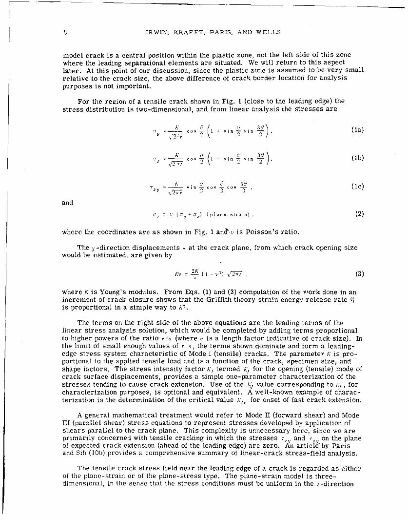
For the region of a tensile crack shown in Fig. 1 (close to the leading edge) thestress distribution is two-dimensional, and from linear analysis the stresses are
cr Z K Cos ; (I (I -i L sin _" , .(la)
cK s (? - 300
T -- ,nco-c'1 3U' (lc): • --= s In -5)cos W cos -1c-"r Y 2,2 '2
and
c, : Z (cV y + o-) ( pl ane- strain) . (2)
where the coordinates are as shown in Fig. 1 anctv is Poisson's ratio.
The y -direction displacements , at the crack plane, from which crack opening sizewould be estimated, are given by
E 7 T (1 - r (3)
where .' is Young's modulus. From Eqs. (1) and (3) computation of the work done in anincrement of crack closure shows that the Griffith theory strain energy release rateis proportional in a simple way to K2 .
The terms on the right side of the above equations are the leading terms of thelinear stress analysis solution, which would be completed by adding terms proportionalto higher powers of the ratio ra (where a is a length factor indicative of crack size). Inthe limit of small enough values of r;'a, the terms shown dominate and form a leading-edge stress system characteristic of Mode I (tensile) cracks. The parameter K is pro-portional to the applied tensile load and is a function of the crack, specimen size, andshape factors. The stress intensity factor K, termed A', for the opening (tensile) mode ofcrack surface displacements, provides a simple one-parameter characterization of thestresses tending to cause crack extension. Use of the },, value corresponding to K, , forcharacterization purposes, is optional and equivalent. A well-known example of charac-terization is the determination of the critical value Kt, for onset of fast crack extension.
A gencral mathematical treatment would refer to Mode II (forward shear) and ModeIII (parallel shear) stress equations to represent stresses developed by application ofshears parallel to the crack plane. This complexity is unnecessary here, since we areprimarily concerned with tensile cracking in which the stresses i- and -r on the planeof expected crack extension (ahead of the leading edge) are zero. An article by Parisand Sih (10b) pro,.ides a comprehensive summary of linear-crack stress-field analysis.
The tensile crack stress field near the leading edge of a crack is regarded as eitherof the plane-strain or of the plane-stress type. The plane-strain model is three-dimensional, in the sense that the stress conditions must be uniform in the o-direction

NRL REPORT 6598 9
across a leading-edge region which is large compared to the size of the zone containingplastic strains. The plastic zone is then held within a plane-strain stress system withits size somewhat reduced by elastic constraint. Of course, if the crack is what we terma "through-crack" with leading edges right through the plate thickness, even if the plas-tic zone is small, a plane-strain condition near the £ree surfaces is not possible. Cus-tomarily the linear analysis applied to crack problems of this kind is the one termedgeneralized plane stress in which c = o is assumed. In this case Eqs. (1) remain appli-cable with the stresses interpreted as averages through the plate thickness. Such amodel is two-dimensional, since the z -direction dimension plays no role in the analysis.The effect of assuming c- = o, instead of Eq. (2), is to eliminate the factor (I - :I2) fromEq. (3). The two-dimensional plane-stress situation permits larger shear stresses andthus a larger plastic zone size than would occur, with the same stresses n the x, y plane,for plane-strain. The relation of this to the brittle-ductile change in fracture toughnessis discussed later.
From Eqs. (1) A' is the limiting value on & = o of the product 1 \12ir as r approacheszero. Given any valid stress analysis solution for --y , even though it is not expressed inthe r a power series form, the preceding limiting process may be used to obtain thevalue of A'. In fact, if a small-flank-angle notch of root radius P is subjected to the nom-
inal stress 7., and if the stress concentration factor I, is available as a function of p,
then
A" Lin iv2 1\9' \`' -•, (4)
In calculating !,'> from tensile fractures of circumferentially notched round bars,Eq. (4) along with published stress concentration factors pertaining to that geometricalshape, furnished the first approximate answers. The procedure is reviewed by Parisand Sih (10b).
The same basic analysis rules apply to determinations of %, for a laboratory speci-men, with a crack of controlled size and shape inserted for testing, as are used to deter-mine A' for a crack in a service component. However, for the most used types of labora-tory specimens the analysis accuracy has been improved by considerable numericalwork. In the case of cracks in service components the estimates used are usually of the"engineering approximation" type based upon one or more of the crack stress field re-sults discussed next.
For an infinite plate subjected to an in-plane uniform stress 0, perpendicular to athrough-the-thickness crack of length 2a,
K . (5)
Cutting this configuration in half results in a through-crack of length a into the edge of asemi-infinite plate with the s.•ress c- parallel to the edge, where
A z 1. 13 r \i-7 . (6)
The 1.13 factor may be regarded as the correction factor ior increased crack openingdue to the free surface.
For a strip of width Iv with a central crack of length 2a perpendicular to a longitudi-nally applied stress (7, approximate values of A' can be obtained from
(I s (! c (7)
where a . 3.

10 IRWIN, KRAF'FT, PARIS, AND WELLS
Returning to the idea of calculating h' as a limit, the addition of any uniform tensionor compression to a crack stress field solution would not change the value of A', becausethis would not change the limit of the product c-! \2n as r approaches zero. Thus, if auniform compressive stress numerically equal to c, is superimposed on the problem ofEq. (5), the A' value is not changed. However, the stress , at infinity is thereby canceled,and a uniform pressure numerically equal to - is placed on the crack surfaces. In thisway we see that Eq. (5), with c- replaced by p, provides the answer to the problem of atwo-dimensional crack of length 2a opened by an internal pressure p. If both a (at infin-ity) and p (on the crack surfaces) act at the same time, the A: value is obtained by substi-tuting,- + , for c.- in Eq. (5). Similar comments pertain to the influence of internal pres-sure, say from hydrogen, in connection with the three-dimensional problems discussednext.
For a circular (penny-shaped) crack of radius a imbedded in an infinite, three-dimensional body with uniform stress c applied perpendicular to the crack,
A' Z 2 a •a_. (8)17
This is really a special case of a similarly oriented elliptical crack of semiminor axis aand semimajor axis b. At the semiminor axis, where K is largest,
a -/Tý - (9a)
and
~ ~' - 6-a 2 n2 f O ~I.
where (D. is recognized as the complete elliptic integral function whose values are:aib = 0, 0.1, 0.2, 0.3, 0.4, 0.5, 0.6, 0.7, 0.8, 0.9, and 1; (o = 1.0, 1.016, 1.051, 1.097,1.151, 1.211, 1.277, 1.345, 1.418, 1.493, and i/. For the extreme values of a.'b Eq.(9a) leads to Eq. (5) or to Eq. (8), as would be necessary. Thus, ,I,0 can be regarded as acorrection factor for the elliptical nature of the crack shape.
Influences upon the K value of proximity to a free surface and changes of crack shapecan often be approximated in a simple way with good enough accuracy for practical ap-plications. Equation (6) is known to be the free-surface modification of Eq. (5) fromnumerical calculations. Equation (7) is simply an approximate empirical representationof the results from numerical calculations for a central two-dimensional crack in afinite-width plate. Comparisons to accurate numerical results, when these becameavailable, showed Eq. (7) was preferable to a tangent function representation previouslyused.
Often the shape of a surface crack suggests representation of the crack as half of anellipse with the principal dimension at the surface of the plate. The analysis problem isa difficult three-dimensional calculation, and exact numerical results are not available.However, from comparisons of test results, the controlling A' value for this problem canbe estimated using the equation
1. 12 ac V' _( D (9b)
The factor 1.12 was guessed from comparison to the problems represented by Eqs. (5)and (6) at a time when the third significant figure of the coefficient in Eq. (6) was notwell determined (11). Careful measurements of I,/, using semielliptical cracks and

NRL REPORT 6598 11
Eq. (9b) have agreed well with A'il values from other methods, so long as the value ofwas not more than ha!f the plate thickness (10c).
Experimental Fracture Mechanics Analysis
In view of the inherent difficulty of some three-dimensional crack stress field prob-lems, experimental methods of determining K will be briefly reviewed. The first ofthese employs compliance measurements and leads directly to values of . rather than A.For tensile cracks the relationships connecting ( and K are
(I 1 - V2)(plane strain) (10)
and( n stress). (11)
Figure 2 shows a single-edge-notched plate specimen sometimes used for cracktoughness measurements. This is % through-crack problem for which a generalizedplane-stress analysis viewpoint is natural. The experiment consists in repeated meas-urements of specimen compliance with the crack-notch depth into the specimen fixed at aseries of values, say from 0. Lw to 0..W, where w is the specimen width. If P is the ap-plied load and f. is the total load displacement (oetween the two loading points) the com-pliance C is given by
C = t/.,' (12)
In a graph of P as a function of t, for a series of in-creasing crack depths a, each load-unload line would havea slope i'c which would be a decreasing function of thedepth a. Simple analysis of the strain energy lost fromthe specimen in a small increment (in of crack extensionshows that energy loss per unit of plate thickness B isg i v e n b y =
G P" d)(13)02 B, da
The expression for K 2 can be written in the form
K 2 = I (P 2_) d(EBC) (14) I•-= d' alW)Iý,I-. 13 f a--V
where the final derivative term is dimensionless and, for Ia long specimen, depends only on the relative crack depth Ia'71. As discussed by Brown and Strawley (lOd) compari-sons of K from compliance measurements to numericalcollocation-analysis values of K can be done with sufficientaccuracy to show agreement within about 3% for the spec-imen of Fig. 2, and equivalent agreement has been found
using notched bend specimens. When this method is ap-plied in a simple way to three-dimensional problems andA does not have a constant value along the entire leadingedge of the crack, the method provides only the average Fig. 2- Single-edge-value of h" across the leading edge. notch specimen

12 IRWIN, KRAFFT, PARIS, AND WELLS
Attempts to measure .' based upon determinations of stress near the leading edge ofthe crack, either with photoelp L.icity or with bonded strain gauge methods, have not beenequally successful. Approximate answers can be achieved, but errors of 10% to 15%have been apparent in work of this nature to date. The reason is probably the dependencyof the definition of A* upon a limiting process in which the distance r must approach zero.In the compliance technique an uncertainty as to the exact location of the leading edgecontributes only a small error. However, the leading edge location is of critical impor-tance to the photoelastic and bonded-strain-gauge methods. Further study of the posi-tioning of the leading edge of the crack for analysis purposes will be required to reducethe existing analysis uncertainties.
Other experimental methods are possible which may well be more accurate thanthose discussed above but which have received very little trial. Two such methods wouldproceed as follows: (a) Calibrate a test material for fatigue striation spacing as a func-tion of K in tension-tension fatigue; then use measurements of striation spacing to meas-ure h' values ior crack geometries of interest. (b) Form a model of the component of in-terest from glass or another suitable transparent material. Move a crack into the modelas desired using a fixed, low humidity to assist stable crack extension. Measure crackopening displacement as a function of distance from the leading edge using optical tech-niques and interference fringes. Use Eq. (3) io obtain A.
Except for reservations based upon accuracy troubles, frozen-stress photoelasticitymethods might seem well suited to the determination of ratios of K to applied nominalstress for, say, deep cracks in the throat regions of'nozzles. The results from frozenstress methods would have improved value if these results could be checked using a dif-ferent technique such as one of those suggested above.
When artificially inserted increments of crack extension are used, along with thecompliance technique, to determine K values for the specimen of Fig. 2, the extensionsare straight across the plate, because this is the natural path for tensile mode crack ex-tension. In general, the natural trajectory for a moving tensile crack may be a curvedsurface. Where this surface is not known in advance, it can usually be determined bythree-dimensional model studies, using fatigue or stress corrosion to produce stableextension of the crack. The determination of K for a crack or slot which does not corre-spond to a natural tensile mode crack surface is complicated by the fact that the leadingedge stress system will contain contributions from Mode II and Mode III stress fields.In the case of the single-edge-notched plate or a notched bend bar K,'jc test, availableanalysis methods provide only the average value of A'2 along the nearly Straight leading
edge of the crack. The actual value of A,'2 in central regions should be larger than theaverage value of A'2, but the amount is uncertain. Some investigators estimate the in-crease factor as the reciprocal of (i - Z,). Others report a value of A'/ which may beconservative (possibly by as much as 5%) by taking the central region K,1- value as equalto the average K,2 across the specimern. The difference is of small practical importance,since replicate test results tend to vary by amounts in the range of 5% to 10%.
PLASTICITY ANALYSIS CONCEPTS FOR CRACKS
Studies of fracture suggest that a close relationship to plastic flow properties exists.It is impossible to explore interests of this kind in a quantitative manner without usinganalysis models to define properties which can be computed as well as observed and dis-cussed. Exact elastic-plastic solutions are not available for the tensile cracks whichare of interest. Furthermore, the structural metals possess fine-scale imhomogeneities,and this limits the realistic accuracy of any continuum mechanics representation. De-spite these difficulties, significant progress has been made with the aid of several rela-tively simple analytical methods. Three elementary and widely used plasticity analysisconcepts for cracks are described next.

NRL REPORT 6598 13
The r Y Plasticity Adjustment Factor
Critical values •" for onset of rapid fracture in high-strength aluminum alloy sheetswere among the first crack toughness measurements attempted. These employed tensilesheets of various size with a central, sharp-ended slot to represent the initial crack.Results showed a trend for , to increase with the lateral dimensions of the specimen,which was nearly eliminated by adding a plasticity adjustment r y to the crack size (12).
No specific model of the plastic zone was attempted. The idea was simply to re-move a leading edge positioning error from the linear elastic analysis model. A centralposition inside the plastic zone, as shown in Fig. 1, was assumed to be a better locationfor the analysis model leading edge than the apparent tip of the crack at the left side ofthis zone. From Eqs. (la) with , =
,7 = Y '\2 . (15)
It was assumed that the distance rY from the central location to the elastic plastic bound-ary could be es t imated by inserting a critical yield stress value 0'y for (-, in Eq. (15) andthat this distance could also be taken as the separation of the analysis model leadingedge from the apparent tip of the crack (13). From these rules
i (-L) (16)27r \cry)
In fracture testing applications the value of cr was taken to be the 0.2%-offset uniaxialtensile yield strength cy.- for situations of plane stress. The length factor 2ry was usedas an approximate estimate of the size of the plastic zone. The influence of plane-strainconditions in elevating the tensile stress necessary for yielding was assumed represent-able by taking uy = :3- c-YS
Crack toughness testing of the plane stress kind is not yet carefully defined. Withinthe limited accuracy of available results for onset of rapid crack extension in high-strength metal sheets, use of the leading edge positioning adjustment ry results in kvalues which are essentially constant with change of test sheet size, so long as the netsection stress is less than cYS.
Historically, the length factor 2ry was used as an approximate estimate of the plas-tic zone size. Studies of the change in the ratio of 2ry to test-plate thickness across thebrittle-ductile fracture mode transition range showed clearly the dominating influence ofelastic constraint and led to interpretation of this fracture transition as a change fromplane strain to plane stress in the leading-edge plastic zone (13). Clark (14) investigatedthe apparent size of the plastic zone in silicon iron both for plane-stress and plane-strain conditions and at a stress level where the net-section stress was well below .He concluded that the size estimates provided by calculating 2ry for plane stress andplane strain were approximately correct both in magnitude and in terms of the 3-to-1size ratio for the two conditions of elastic constraint.
Substitution of ry for r in Eq. (3) permits calculation of 7. crack opening dimensionwhich is interesting for various fracture analysis applications. Wells (15) has usedterms such as crack opening displacement and crack opening dislocation for the crackopening size 2v = ý estimated in this way. He noted that one obtains the result 4q,77T,.Yre-gardless of whether or not a plane-stress or plane-strain condition is assumed.

14 IRWIN, KRAFFT, PARIS, AND WELLS
The Strip-Yield Zone Concept
Linear analysis of stresses near a crack can always be formally done by solving thestress problem, ignoring the crack, and then superimposing a solution which containsforces at the crack plane just sufficient to restore free surface conditions. The analysiscan be adjusted so that, adjacent to the leading edge, the crack surfaces are not force-free but are subject to crack closure forces arising, say, from attraction between oppo-site crack surfaces. Bareablatt (16) assumed that such a system of crack closure forcesalways exists near the leading edge. The closure tensions and their distribution werebalanced, so as to eliminate the linear analysis stress infinity.
Dugdale (17) noted that this idea could be applied to representation of the plane-stress yield zone for a crack in a thin metallic sheet. In this application the force sys-tem became simply a constant tensile stress across the linear yield zone equal to thetensile yield strength. Since Dugdale's analysis ignores the sheet thickness, the analysismodel plastic zone is simply a line segment extending ahead of the apparent tip of thecrack. Concentration of all the plastic strain into a line results in a representationwhich permits calculations of the opening displacement discontinuity but does not permitcalculations of plastic strains.
Interest in this type of representation also developed among dislocation scholarswho saw that a strip yield zone could be thought of in terms of a continuous distributionof dislocations. A criterion for onset of rapid crack extension based upon a criticalvalue of crack opening displacement might, it seemed, provide a way to connect macro-scopic fracturing directly with dislocation mechanics (18). Modifications toward greaterrealism are possible by assuming various line patterns of concentrated yielding at theexpense of greatly increased analytical complexity.
For those with less ambitious analytical objectives there are other reasons for in-terest in the strip-yield model. For example, a single line of yielding can be analyzedwith only moderate computational difficulty for certain tensile fracture specimens whichmight be used for crack toughness evaluation. Wells' crack opening displacement -could be estimated for such tests from the strip-yield analysis model in terms of obser-vations of applied load and crack size, until the yield zone extends completely across thenet section. Only theoretical studies of this kind have been done. These resulted in ývalues not significantly different from the value of (c'cry) resulting from a linear analysiswith the usual r,. positioning adjustment (19).
When the size b. of the strip-yield plastic zone is small relative to.crack size andnet section size, the following relationships hold:
S ~}(17)
and
V277- -- (18)
Examination of stress and opening displacement equations for the strip-yield model, inthe small plastic zone limit, shows that the "best fit" location for the leading edge of alinear analysis model crack is at the distance b0/3 from the apparent leading edge of thecrack. Comparison of
S(19)
to Eq. (16) shows that 1, :1 is smaller than ry by only 18%.

NRL REPORT 6598 15
Compression of all the yielding into a thin layer ahead of the crack might seem toounrealistic to be valuable for thick-section tensile fracturing of metals. However, it ishelpful to learn what concepts associated with various models of the plastic zone havemagnitudes which are nearly independent of plastic strain distribution. Comparison ofEqs. (17) and (19) to the r, values from Eq. (16) suggest that the linear analysis posi-tioning adjustment r . and the crack opening displacement ý are two concepts possessinga considerable degree of strain distribution invariance.
The Mode III Elastic-Plastic Treatment
The system of deformations near the crack border, termed Mode III, is a distribu-tion of shear strains such that all the particle displacements are parallel to the leadingedge of the crack. Limitation of displacements to a single coordinate direction reducesthe mathematical difficulty for linear analysis (with yielding suppressed) and for strip-yield analysis (with yielding confined to a line segment). In fact, Mode III elastic-plasticsolutions can be done without arbitrary restriction of the region of yielding and, for zerowork hardening, with a degree of mathematical difficulty only moderately greater thanthat for the strip-yield analysis. The Mode III plasticity analysis idea introduced byMcClintock and associates (20-22) became of increasing interest as the inherent difficultyof the corresponding Mode I analysis became evident. The reason for this is the need foranalytical representation of plastic strains very close to the leading separational ele-ments of the crack.
If one assumes zero work hardening and either the Von Mises or Tresca criterionfor yielding, Mode III plasticity analysis predicts a distribution of shear strains repre-sentable in the form
S-- + i yz , (20)
where
-Y - -- Co . (21)
-=z Y -7 sin l , (22)
and -Y, - T-jri is the shear strain at the elastic-plastic boundary.
The coordinates r, and 9 are the cylindrical coordinates about an axis coincidentwith the apparent leading edge. R1 is the value of r, if the latter is extended to theelastic-plastic boundary. The preceding result is not generally valid. However, it isvalid for any series of equa!ly spaced, equal-length, two-dimensional cracks on the x-zplane and for a uniform stress r,= -r acting a remote distance from this plane. Thisproblem has received study, because it can be regarded as the Mode III analog for cen-trally cracked, symmetrically edge cracked, and finite-width tensile specimens used forcrack toughness evaluation.
Analytical considerations (10a) show that as the plastic zone reduces in relative sizethe elastic-plastic boundary approaches the shape of a circle (or cylinder) with the co-ordinate axis of I,9 at the left extreme of the p-direction diameter as suggested by Fig. 1.The size 1%0 of this diameter is expressed by
e2 (23)

16 IRWIN, KRAFFT, PARIS, AND WELLS
For comparison, the leading-edge equations for the elastic strains predicted bylinear analysis in Mode ITT are
"")A1 I I coS (24)Y). \2r
and- ill1 sin V• 2')(5
"•'.• = - y),(25)
If we locate the origin of the .* coordinate3 at the center of the plastic zone and putr - 'O.2, Eqs. (24) and (25) predict the same strain as do Eqs. (21) and (22). Thus, thelinear-analysis value of r - for this problem is
r). - 1 (26)
Clearly, Eq. (16) is the tensile analog of Eq. (26).
If we assume le= ,', cog ; I, corresponding to the small plastic zone ';ituation, integra-tion of the total strain y around the elastic-plastic boundary provides the result
"2(27)
Using 2k,4 ';l 1 -1 '• A'1 this equation becomes
S. '7, TT (28)
Equation (28), with -. in place of -T., is the same as the value for s in the case of thetensile mode, when the linear analysis approach was used, supplemented by the leading-edge positioning adjustment rY.
For the Mode III elastic-plastic problem of a finite-width plate, such as was indi-cated above, values of ý have been calculated by Rice (23) as a function of r and cracksize a for various levels of net-section stress. From comparisons to these results onefinds that the value of ý provided by Eq. (28) is still accurate to better than 5% when thenet section stress is 0.9.)r.
An additional result of interest from studies by Rice (24) pertains to the influence ofstrain hardening. Using a nonlinear stress-strain law in the plastic range of the type
0 0Y)* (29)
Rice was able to study the shape of the Mode Ill crack opening and the shift of theelastic-plastic boundary for the small plastic-zone situation with a work hardening in-fluence present. He found that the elastic-plastic boundary remained circular. The di-ameter was still given by Eq. (23), and the crack opening at the intersection of theelastic-plastic boundary with the crack was given by Eq. (28).

NRI. REPORT 6598 17
Fracture Characterization Problems in Relation to Plastic Analysis
As noted in previous sections, much has been learned about progressive crack ex-tension through direct observatiu;i of the behavior trends as functions of K (or C). Thedegree of success thus achieved resulted from giving primary analysis attention to theregion close to the leading edge. Intuitively, a similar procedure should be followed inplasticity studies. Primary attention should be given to regions of the plastic zone closeto the leading separational elements of the cracK. The K or ý; value represents a con-trolling aspect of tie elastic stress field. Presumably, a controlling aspect associatedwith plastic strain would be appropriate in the case of plasticity studies. However, thetask of selecting a simple characterization plan based upon plasticity analysis can onlybe done, at present, on a judgment basis. Essentially, one needs the answer which issought in order to find this answer, a dilemma not uncommon in exploratory science.Two judgment type answers are as follows:
1. Characterization in Terms of the Crack Opening Displacement :. Intuitively, anaverage strain of some kind would seem most promising as a single-parameter charac-terization of critical "state of strain" for onset of rapid crack extension. One specialkind of averaging, potentially suitable, would be that which is measured by the value ofthe crack opening displacement -. Although, conceptually, values of ;- might be obtainedby direct observation, the feasibility of doing these measurements with useful accuracyis still not clear. Calculations of ý can be made, based upon a specific elastic-plasticmodel, as the integral around the elastic-plastic boundary of the extensional strain nor-mal to the crack. A simpler plan would be to compute 3 as equal to qcr,.. Both methodsbecome inapplicable after development of general yielding. Beyond general yielding,estimates of , can be made using a rigid-plastic slip-field viewpoint. Obviously, some-what different values of 3 would be obtained with different methods, and use of 6 as acharacterization parameter in a consistent way would require arbitrary standardizationof the calculation pi'ocedures.
2. Characterization in Terms of a Critical Average Strain c for Plastic Instability.This procedure is based upon Krafft's correlations between kA,, and strain hardening,which suggest that local plastic instability is a significant controlling aspect for onset ofrapid crack extension (25). In the calculation plan used by Krafft the critical averagestrain is assumed given by
(39)
The length factor d'T for a given test material was determined, Ref. 25, by assuming cequal to the strain hardening exponent n for isothermal conditions of straining. Directmeasurement comparisons of A",, and n for similar conditions of strain rate and temper-ature then permitted finding a best-fit proportionality factor. More recently, followingsuggestions by Williams and Turner (26), Krafft assumes
(31)
where the terms on the right represei.t the influence of an assumed specific type of elas-tic constraint on the critical strain for plastic instuibility (27).
It is possible to L.rrive at somewhat similar equatiois by defining an average strainclose to the leading edge in terms of the Mode Im elastic-plastic model, Eqs. (21) and(22), as follows. From the preceding equations, the maximum shear strain at a point(r . ,) is given by

18 IRWIN, KRAFFT, PAII,!S. AND WELLS
(32)
Assuming le' 2r c the average strain along a vertical line at .r , where. r• is given by
(7. 2 ) (33)
A) (34)
The tensile analog of Eq. (34) is
______ ~(35)
In this calculation plan the elastic constraint might be assumed representable by n2
to derive a relationship between I,', and n similar to that p.'ovided by Eqs. (30) and (31).
At present, correlation studies between plastic tiow properties and crack toughnessneed additional support from plasticity analysis. Equation (35) is of no special impor-tance in itself, but the derivation has illustrative values. Plasticity investigations in-tended to assist extension of fracture mechanics toward basic factors at finer scaleshould provide help of that kind in terms of better plasticity models. Previous calcula-tinns of plastic strain fields near a tensile crack using computer programs have not beenplanned so as to assist the characterization rask either in terms of a crack opening dis-placement concept or along the lines of the h', -, correlation.
SLOW-STABLE CRACK GROWTH
Crack Growth Rates With Fatigue
In assessing the severity of flaws in a structure the possibility of their growth to adangerous size from the effects of repeated loading, including cyclic thermal stressesand/or environment, should be considered. Two related approaches have been adoptedfor making this assessment. They are (a) to give attention to an analysis of the growthrates of subcritical flaws (28,29) which can subsequently be used to estimate a "life"from an initial flaw size to the critical size and (b) to give attention to a direct analysisof the "life" of typical flaws (10c).
Of the two approaches the former is more detailed and fundamental and, consequently,lead to a better understanding of service behavior. On the other hand, the latter approachis simpler and has been demonstrated to be adequate for certain analyses of the life ofpressure vessels of very-high-strength metal alloys, such as rocket engine cases (10c).For a full understanding of flaw growth considerations in the design and behavior ofpressure vessels. both viewpoints of the two approaches should be employed.
In the initiation of subcritical growth of flaws due to fatigue, planar defects are mostlikely to develop into growing fatigue cracks. However, in a conservative assessment ofthe danger all flaws and defects are potentially growing cracks with a slight amount ofsharpening. As one might expect, the most severe flaws are normally those which arelargest, in the most highly stressed regions of a structure, and often those in materialwhich is degraded in the process of fabrication.

NRL REPORT 6598 19
The analysis of the growth rates of flaws, from sizes which are too small to find innormal inspection to those of critical size for unstable running fracture, proceeds on asimilar basis of analysis as that for final failure itself. The increment of crack growthexperienced in a cycle of loading depends upon the corresponding excursion in thestresses surrounding the crack tip, as measured by A.
For a given material and environment the rate of crack growth, ,/, 1h1, depends pri-marily on the stress intensity factor range :K and secondarily on the relative mean value
of the stress intensity factor /,', (or relative mean load [,,,), i.e.,
A',f (36),',It h'
Also of secondary (but not negligible) 5.mporttrnce are the frequency of loading, platethickness effects, and processing of material, which should be assessed in a refinedanalysis (30,31).
Since growth rates can be correlated by stress intensity factors, the effect of thelocation of applying the loading and solid body and crack configuration are then known,provided the growth rates are known for some laboratory test configuration at the corre-sponding .'x level. This means that plotting doa (i, vs A•A may be regarded as a basic wayto represent a material's crack growth rate behavior and that the effect of secondaryvariables is to cause shifts in the curve so obtained.-,
Many such plots oi2 do ,in vs AK (or A') for steels are available in the literature(29-33). If the plots for steel are superimposed, a curicus result occurs. For zero-tension loading (, = 0.5) all the data for steels fall very close to each other, i.e., withina factor of 2 (or perhaps at most 3) in the growth rate for a given .,K. For example,Brothers' data (32) on low-alloy medium-strength rotor steels are very close to Carman'sdata on high-alloy very-high-strength rocket engine pressure vessel steels. Moreover,the meager data available on low-strength steels for pressure vessels, such as A302B(34), indicate that they-are no exception. (See Fig. 3.)
I OOO
- ,, !/
""w// , STEELS ALLOYHIGH STRENGTH .;', H.T STEELS
6
-°" - STEELS //
"/ A3021 DAtAe
10'
IDI I IL I I I lII I I I I I I
10 100 1000LK (ksi T'I.)
Fig. 3 - Crack growth rate (in d( as afunction of fatigue cycle range of theA' value 'A

20 IRWIN, KRAFFT, PARIS, AND WE[,IS
Consequently, from the steel data which are now available a rather crude empiricalrelationship may be devised to describe the normal rates of growth of cracks in allsteels in air at room temperature (29.30.32-34). It is
""la (37)
where, referring to Fig. 3,
C 1.Ox 10 (for mean data on medium and low-strength steel),
1.6x 10- (for mean data on all steel),
c, = 2.Ox 10 12 (for conservative estimating of fastest rates on all steels).
d\ = in./cycle,
and
A = ksi \ in.
Equation (37) gives a reasonable estimate for growth rates from 10-6 in./cycle up tofinal failure, provided the cyclic A, stays below K'1 0 for the material and the cyclic nomi-nal stress is below the static yield point. These restrictions normally offer no loss, ingeneral, in describing flaw behavior in relatively thick pressure vessels of conservativedesign.
This crude relationship. Eq. (37). may at least be used to estimate whether fatiguecrc ,go, is a real problem or not for an anticipated flaw in a steel pressure vessel.
For example, for a known or anticipated flaw one may estimate the stress range and,subsequently, the range of K (or :%K). Using Eq. (37), an anticipated rate of growth maythen be estimated. The relative severity of flaws of various sizes and locations maythus be estimated also. In this manner Eq. (37) provides useful information of fatiguecrack growth rates expected in vessels.
However, Eq. (37) is not recommended for actual estimates of the fatigue life ofvessels. By itself it is too crude aii empirical relationship for this purpose. It does notcontain the effects of mean load, frequency, environment, or temperature, which surelyplay a role in the flaw growth fatigue life of vessels. For estimating flaw growth liveswith some precision one must revert to the fundamental concept of measuring fatiguecrack growth rates in laboratory tests which simulate the -K./'-levels under conditions ofmean load, environment, and temperature experced in a vessel. Under the expected con-ditions the rate of crack growth drz (IN vs the st):ess intensity factor range tA' may beplotted to give the basic behavioral pattern of the material being tested. Differences inmaterials may be readily observed by comparisons of such curves. Moreover, carefullyobtained data as represented on these curves may be used to estimate the fatigue crackgrowth life of a vessel. A numerical integration of crack growth rates from the initialflaw size to the critical size precipitating failure is all that is required to make suchestimates (30,33).
Data on fatigue crack growth rates under expected environmental conditions are notyet available for pressure-vessel steels. Nevertheless, data which are available on air-craft materials (30,35) and some data taken on pressure-vessel steels (36) with an un-fortunate choice of specimen configuration (the A' levels cannot be computed) allow sometentative conclusions to be drawn on the effect of environment on fatigue crack growthrates. The presence of water (or high humidity) tends to accelerate fatigue crack growthrates in pressure-vessel steels, as well as others. For example, data (37) on A302Bincicate that simulated boiler water increases the rates of fatigue crack growth by amaximum factor of 2.5, whereas for salt water the factor is about .3. (See Fig. 4.) Data

NRL REPORT 6598 21
000 /
- II/ i
rWET-.J
SIOO) I10 _ /'-DRY
- I/
I A201B 8 BA302B DATA
,o 1 1 1 1, ,PI , I I1000 10,000 100,000
Fig. 4 - Crack growth race da'd\ asa function of displacement range inlow-cycle fatigue testing. Data fromCrooker and Lange (11).
on A201B show virtually identical behavior, which leads one to conclude that a factor of 3is rather reasonable for A302B. These factors may be directly applied to the estimatesfor crack growth rates made using Eq. (37) discussed earlier. Though this factor of 3 isan approximation, since it is obtained from a test for which stress intensity factors can-not be computed, its precision is at best consistent with the precision of Eq. (37) itself.
The more precise and fundamental approach of simply gathering and plotting dataon a dn d& vs A* basis is preferred. It is implied that
d .\ = F(') . (38)
where h(A') is a function which depends on the material and environmental conditions.Equation (37) is representative of the gross features of the function r(K),, which showsthe main trend but not the details.
Similarly, one may recall that the stress intensity factor formula for any givensolid-body configuration depends linearly upon the load P and also in some way upon thecrack size, i.e.,
A' Pf(a). (39)
In general, Eq. (39) may be substituted into Eq. (38), which may be integrated to give the"life" Al F of a given configuration of a given material and environmental conditions. Thelife %', can be written as a function of the load P and, alternatively, either the initial andfinal crack size or stress intensity factor values. The form is
"r" •'F ý I1,( P ' , ' ai a (40a)
or½V = /l•( P, h'• , A~c) . (40b)

22 IRWIN, KRAFFT, PARIS, AND WELLI.S
where I/, and if, depend upon the material and the environment and upon the effect of the
configuration through the form of the variation in its stress intensity factor with cracksize.
From Ref. lOb and others on stress intensity factor formulas, it may be casually
r~oted that for flaws which are relatively small compared to other body dimension, theformulas take the form
A -' .z : C ,4 (41)
where .- is the nominal stress on the crack plane and c, takes on values from 2 7, for anembedded circular crack of radius a to 1, 12 %,77 for a long surface crack of depth a or anedge crack in a sheet. For typical flaws which cause concern in pressure vessels, e.g.,surface flaws which are of fairly similar proportions, the coefficient c, is nearly alwaysthe same value. It is therefore reasonable as well as informative to combine Eqs. (37)and (41) to observe the broad trends of variables in life calculations as implied by Eqs.(40). Making the substitution of Eq. (37) into Eq. (41) gives
Rearranging and integrating leads to
ia 2da \ý( 4 (IN
or
A 'F ( a(cr)1 ia (42)
or again making use of Eq. (41)
C7Au)2 - (43)N F C A 2 _ C
Note thai E"s (42) and (43) are the rough approximations of the forms of Eqs. (4'where (" and c7' are constants which depend upon the material and environment I to alesser degree on the configuration of the flaw or crack.
Some important conclusions on flaw growth life may be extracted from Eqs. (42) and(43). First, if the initial flaw size c, (or A'j ) is small compared to the critical size a,
(or , then moderate changes in the critical fracture toughness h, (or a,) have littleeffect on the flaw growth life. This is the case of moderately "high cycle fatigue." It isonly in the case where the initial flaw size is nearly the order of magnitude of the criti-cal size that the critical size or A,, becomes important. This case is relatively "lowcycle fatigue." Moreover, Eq. (43), upon lumping the material constant K,- into c',becomes
C' ( 2
(44)
Quite independently of the derivation of Eq. (44), Tiffany (10c) and others have observedthat data on the lives V+ of flawed laboratory test specimens and typical structures of a

NRL REPORT 6598 23
given material are correlated very well in terms of K, K,., provided that the stressranges v- were roughly comparable. Moreover, Eq. (44) has a certain measure of ap-peal to those who follow the Coffin-Manson type of approach to low cycle fatigue, wherethe relationship (Ao) .\ = constant is observed to correlate data for many materials.Equation (44) implies agreement to this relationship and that "life" also depends stronglyon initial flaw size a, or stress intensity level A,.
Equation (44) is only the result of crude approximations for the detailed behavior offlaws growing by fatigue loading, Eqs. (37) and (41). Though it would be inadvisable toapply it directly, using it to study the significant variables and to understand their rela-tive roles is quite appropriate. That is perhaps best done as originally suggested byTiffany (10c) through plotting test data on K-,> K, vs '%'F to observe effects of flaw size, en-vironment, etc., in a way which lends itself to selecting proper materials and assessingdirectly the severity of subcritical flaws. Again, some preliminary data (34) on flawlives in A302B are shown in Fig. 5. These data indicate lives of thousands of cycles forflaws about 4 in. or more in depth a and breadth b when cycled at half the yield strengthin A302B base metal plates tested dry at room temperature. Similar tests should beperformed on welded plates and with various typical environments for pressure vessels.
1000
0 A302B DATA8
10
1000 10,000 100=0NF
Fig. 5 - Cycles to failure as a func-tion of the initial K value A., Datafrom Clark and Wessel (8).
"T£c method of plotting data on Fig. 5 also implies the value to overload proof testingin assessing the remaining cyclic life (lOc). Since K is proportional to load P, if any flawsurvives an overload the overload K must be less than A',; or, as a consequence, its ini-tial V' at operating load Ki must be less than A' multiplied by the ratio of the operatingload to the proof load ;'il, , i.e.,
-- <P (45)
Moreover, the proof load can be deliberately applied at a lower temperature where K,(low temperature) is lower. Assuming the A', values are known at both temperatures, then
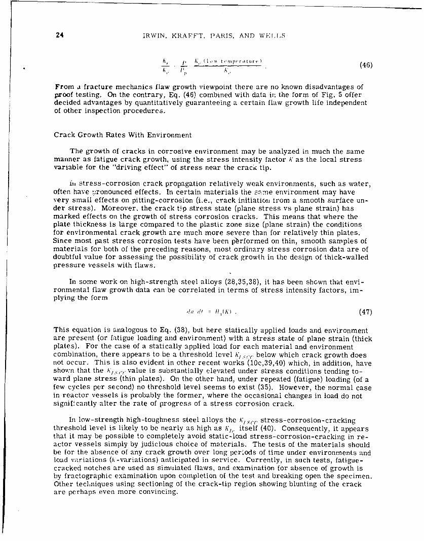
24 iRWIN, KRAFFT, PARIS, AND WEI..S
, ,. I ... t ,.,p, ,r (46)C. I' K',
From a fracture mechanics flaw growth viewpoint there are no known disadvantages ofproof testing. On the contrary, Eq. (46) combined with data in, the form of Fig. 5 offerdecided advantages by quantitatively guaranteeing a certain flaw growth life independentof other inspection procedures.
Crack Growth Rates With Environment
The growth of cracks in corrosive environment may be analyzed in much the samemanner as fatigue crack growth, using the stress intensity factor K as the local stressvariable for the "driving effect" of stress near the crack tip.
in stress-corrosion crack propagation relatively weak environments, such as water,often have --,ronounced effects. In certain materials the Same environment may havevery small effects on pitting-corrosion (i.e., crack initiation from a smooth surface un-der stress). Moreover, the crack tip stress state (plane stress vs plane strain) hasmarked effects on the growth of stress corrosion cracks. This means that where theplate thickness is large compared to the plastic zone size (plane strain) the conditionsfor environmental crack growth are much more severe than for relatively thin plates.Since most past stress corrosion tests have been pbrformed on thin, smooth samples ofmaterials for both of the preceding reasons, most ordinary stress corrosion data are ofdoubtful value for assessing the possibility of crack growth in the design of thick-walledpressure vessels with flaws.
In some work on high-strength steel alloys (28,35,38), it has been shcwn that envi-ronmental flaw growth data can be correlated in terms of stress intensity factors, im-plying the form
,Ia I!, s ( A') (47)
This equation is analogous to Eq. (38), but here statically applied loads and environmentare present (or fatigue loading and environment) with a stress state of plane strain (thickplates). For the case of a statically applied load for each material and environmentcombination, there appears to be a threshold level K, .:. below which crack growth doesnot occur. This is also evident in other recent works (10c,39,40) which, in addition, haveshown that the K,1 .. ,,* value is substantially elevated under stress conditions tending to-ward plane stress (thin plates). On the other hand, under repeated (fatigue) loading (of afew cycles per second) no threshold level seems to exist (35). However, the normal casein reactor vessels is probably the former, where the occasional changes in load do notsignifcantly alter the rate of progress of a stress corrosion crack.
In low-strength high-toughness steel alloys the K,:r(c stress-corrosion-crackingthreshold level is likely to be nearly as high as h,, itself (40). Consequently, it appearsthat it may be possible to completely avoid static-load stress-corrosion-cracking in re-actor vessels simply by judicious choice of materials. The tests of the materials shouldbe for the absence of any crack growth over long periods of time under environments andload variations (A,-variations) anticipated in service. Currently, in such tests, fatigue-cracked notches are used as simulated flaws, and examination for absence of growth isby fractographic examination upon completion of the test and breaking open the specimen.Other techniques using sectioning of the crack-tip region showing blunting of the crackare perhaps even more convincing.

NRL REIiORT 6598 25
However, if 'he A.. is determined to be significandly below K¢,r then several al-ternative considerations must be suggested. First, the time to failure (or rates ofgrowth) for cracks with applied A' levels above K 1z 1 . should be determined (10c.39,40).Normally, these times are relatively short, i.e.., a matter of minutes or a few hoursfrom first load application. Consequently, a reactor vessel with a flaw stressed abovek;,(., would fail in a short time unless it is protected from the environment, or unlessplane stress conditions prevail for cracks through the wall. In some cases, protection ispossible, but it is riot in general. In the cases where protectiorn is not possible, the fa-tigue analysis should obviously be terminated at A',•c(, (i.e., replace ', in Eqs. (40)through (46) with K / .,with a corresponding change in interpretation). Above Aeither there is no significant life remaining or, if plane stress conditions occur atA-levels between k1 s(.(, and K',( , there is some chance of arrest or inhibition of staticstress corrosion crack growth, whereupon the fatigue crack growth mechanism mightagain prevail. Again, this is an area where little work has been done, especially on low-strength high-toughness materials.
In summary, for corrosion considerations / or its equivalent should be estab-lished for the materials considered in reactor vessels. Hopefully, A,.c, will be veryclose to h, , and no special provision for stress corrosion cracking need be made in ad-dition to that in the fatigue crack growth analysis (with environment). However, if Kl.,cis appreciably below K,, , then either k/..( should be used as the "failure level" in de-sign, or special procedures must be developed to assess the remaining life.
CRACK PROPAGATION AND FRACTURE TOUGHNESS
Measurements of A', and A,.-, for Very-High-Strength Metals
Crack toughness measurements based upon linear crack stress field analysis lead tocritical values of the stress intensity factor A' for either onset of rapid fracture or crackarrest. Measurements of crack arrest A values are less common, mainly because suchtests require larger amounts of material. Similarly, for reasons of convenience, thetesting speed most often used has been slow. The loading time to fracture in slow testingis usually about 2 min. The primary interests supporting A' and Ai1C test developmentpertained to very-high-strength metals for use in rocket or ordnance applications. Ref-erence 10 provides an adequate review of this subject and this discussion will summarizeonly selected major points.
Onset of rapid fracture and crack arrest are naturally of interest for use as cracktoughness measurement points, in part because they tend to occur abruptly and in partbecause present knowledge suggests no alternative choices. In the slow-stable and fast-stable regions of crack extension the average crack speed changes continuously in re-sponse to changes in the value of K or C,. The in-between points called onset of rapidfracture and crack arrest, under ideally brittle conditions, appear to be true instabilitypoints at which there is an abrupt upward or downward jump in the crack speed. Astoughness increases and the plastic zone grows in size, the crack length for onset ofrapid fracture becomes more difficult to select unambiguously in a simple way. Evenfor plane-strair. •',, testing, material properties leading to unexpected amounts of stablecrack extension prior to onset of rapid fracture sometimes occur. After some years ofstudy the ASTM E-24 Committee recently approved for trial, as a tentative K", testingstandard, a method remindful of a percent-offset tensile yield strength testing practice.
In it and A',,, testing some stable crack growth prior to the measurement point isexpected, because the natural contour of the leading edge of the crack at the fracture loadusually differs from the crack shape inserted, say by low stress fatigue. When the speci-men has a through-crack as in Fig. 2, plastic yielding near the plate surfaces results inadded stress on central regions of the leading edge. The central region then advances.

26 IRWIN, KRAFFT, PARIS, AND WELLS
Whether this advance takes the form of an unstable plane-strain "pop-in" or appearsgradually depends uj.on the lengtl-, of the leading edge segment, which becomes nearlyunstable at the time of forward movement. From experience, a pop-in often occurs whenthe plate thickness I. is more than 4 times the plane-stress value of 2r, and nearly al-ways occurs when i; is more than IO( 2ry . Also, from testing experience, a substantialstable forward motion of central regions of the crack can be assumed to be governed bya A,1 ,- level of K so long as environment effects, which would cause continuing stablecrack extension, are absent.
In A,. testing of very-high-strength steel and aluminum alloys, the test method ofRe'. 41 employed an ink-staining technique to mark the region of slow stable extensionprior to onset of rapid fracture. Analysis of these results showed stable extensionsrarely less than r) and rarely more than 2 r . (10a), where these length factors werecomputed on a plane-stress basis regard.css of the degree of plane-strain influendingthe test result. The presence of water in the ink no doubt assisted the obse-:ved stableextensions. However, most of these tests used Elox notches (about 0.002 in. root radius).and this tended to reduce the stanle growth. Generally, a stable crack extension about *r,
it, size is expected as normal behavior and represents. primarily, readjustment of theleading edge contour toward the shape most natural for the onset of rapid fracture insta-bility which severs the specimen.
Roughly speaking, the present A*,,- testing method favored by ASTM E-24 assumesthat, when the load-deflectir', curve indicates skable crack growth of more than rY. aload corresponding to the A',, value has been achieved. Other details of the test methodtend to encourage use of large enough test specimens so that most tests will terminatewith an abrupt onset of rapid fracture prior to visible indications of stable growth. Nochange in the average level of A,, test results from those using presently customarymethods is expected.
During the past 8 years many thousands of ,', and A'/C test results were reportedfrom test methods suggested by the currently available technical literature. Results re-ported in Refs. 10 and 27 are typical. One finds the scatter band for a group of resultsfrom similar specimens of the same plate material usually extends from 5% to 10%above and below the mean value. Welded regions tend to have larger va:riaLions of mi-crostructure and impurities, and the scatter range of test results i" larger. The K,10values reported by Kies et al. (10e) for various welds in ultrahigh-strenizth maragingsteel show ±15% to ±25% scatter bands for central regions of the welds. They reportedthat these variations correlated with variations in qua Uity of microstructure in the localregion tested.
The difference in test result scatter between fracture toughness tests and tensileyield-strength jests corresponds in part to the contrasting influences of small defectsupon these properties, as discussed previously in this section. The larger defects,which tend to be less uniform in distribution, influence the crack toughness but do notinfluence resistance to plastic deformation. An additional factor is related to the test-volume size.
When the size of the fracture toughness specimen is increased, the leading edge ofthe crack samples a larger volume of material. The result is a reduction in the absolutesize of the test-result scatter zone. A corresponding reduction of average critical P.value should occur in accordance with a "worst flaw" statistical treatment of the prob-lem. In the case of A', evaluations using through-crack type specimens, one dimensionof the test volume is the plate thickness, diminished by regions comparable in size to 2,(plane stress) adjacent to the test-plate surfaces. The area one would use in completingthe test volume estimate would be the square of a small dimension intermediate in sizebetween - and r, (plane-strain) and might be guessed as simply the product of theselength factors. Such a test volume is quite small. Yield-strength tests respond to the

NRL REPORT 6598 27
average critical stress through a test volume comparable in size to the cube , the test-bar diameter, a volume several orders of magnitude larger than can participate in de-termining a A,"(. test result.
The substantial scatter of test results inherent to crack toughness measurementshas a definite bearing on a fracture control plan which assumes that certain levels ofcrack toughness, established by testing, will be present as a barrier to crack propaga-tion. There are no conventional methods for selecting a worst K,, value for a -)articularapplication on a probability basis, other than straightforward statistical theory.
On the basis of statistical theory, suppose AK,, tests, say of an electroslag seamweld, have been done in sufficient number to permit determination of the standard devia-tion 'T. Then a Weibul theory flaw distributiot. exponent in can be estimated (41) from theequation
K - 1.2 (48)(K i% m
From the statistical th•:ory the average A',, for a large crack through the wall thickness1) should be less than that for the small test cracks in specimens of thickness B3, in ac-cordance with the equation
r 13 0 1 fnm(49)
The value of applicable to the large cracks would be reduced in size by the same factorI m" Several times this reduced 5 value would then be subtracted from the large-
crack '"1 • to determine a conservative estimate for'the service vessel. The details ofthis would depend upon judgment factors best settled at a later point in fracture controlplanning.
The Brittle-Ductile Fracture Transition
During fracture investigations associated with welded steel rocket chambers for thePolaris and Minuteman programs, K, measurements were made on a variety of ultrahigh-strength metals. It was noted that the percentage of oblique shear on the fracture sur-face showed a trend-type correlation with the dimensionlss ratio
~ (~~)~(50)plIan t ir es s
Since
(K, L (51)
is regarded as a formal measure of plastic zone size, the ratio of plastic zone size toplate thickness was ,2,. 'n,.As was noted in Refs. 13 and 42, less than 50% oblique shearwas usually present when 9, < 7-. Furthermore, the condition 3, = 77 represented one inwhich the value of i', as a function of 8,, was increasing rapidly. Clearly, /3 77 repre-sented a midrange condition for the change from a flat-tensile fracture with relativelysmall shear lips to an oblique-shear fracture with substantially increased fracturetoughness. The ,,, :7f criterion for midrange behavior was the same regardless ofwhether the fracture transition was induced by changing the testing temperature or by

28 IRWIN, KRAFFT, PARIS, AND WE. I.S
changing the test-plate thickness. In the case of high-strength aluminum, K, did notchange apprec,,tbty with temperature (excluding temperatures below -250 F) but oc-curred with changes of test-plate thickness in the same manner as for steels.
At the time of Ref. 13, fracture toughniess data for several rotor steels at about100 ksi yield strength were available. Tese showed the same behavior pattern relativeto the brittle-ductile transition as did the high-strength metals. With regard to low-strength mild steel plate material, only approximate estimates of fracture toughnessbased upon crack arrest tests were available. However, rough estimates of using anelevated dynamic yield strength were maue. The same correlation between and frac-ture transition was again evidenced.
A clear mechanism exists for the control of the brittle-ductile transition in terms ofthe plastic zone size. For a plate in tension containing a round hole straight through theplate thickness, the thickness direction stress close to the hole at midthickness of theplate shows a large amount of plane-stress relaxation, unless the hole diameter is lessthan half the plate thickness (43). From "-is, we expect that plane-strain confinement ofthe plastic zone will disappear as we int._,ase the plastic zonc size factor 'r) relative tothe thickness of the fracture test specimen. If we allow the open hole a moderate advan-tage over the crack tip plastic zone in causing thickness direction stress relaxation, the
.-- criterion for a midrange fracture transition condition is quite plausible.
The crack opening displacement - decreases with testing temperature for a steeland thus changes in size relative to the grain size and relative to Krafft's I Altera-tions of this kind may have a bearing on the appearance features of a flat-tensil, frac-ture, for example, upon the fraction of the exposed fracture surface composed of cleav-age facets. However, the role of fracture appeazances in relation to macroscopicfracture toughness is still not very clear. Notthed bar fracture tests of steels conductedat a series of temperatures and with a series of specimen sizes do not show one fracturetransition associated with crystalline cleavage and a second transition associated withthe relative size of the plastic zone. Only the transition associated with relative plasticzone size is consistently observed.
Several tensile fracture tests were performed at the Naval Research Laboratoryusing 60-in.-wide 3/4-in.-thick 2024-T3 aluminum plates, centrally notched. The tough-ness was so large that the average net-section stress roughly equaled the yield strengthat the load for crack propagation. However, the first test produced a flat-tensile fracturenormal to the plate surface extending nearly to the side boundaries of the specimen. In asecond trial, the hacksaw extension of the central slot was tilted to 45 degrees with theplate surfaces. This time the fracture was entirely oblique shear, but the load and net-section stress did not differ significantly from that for the first test plate. According toJ.G. Kaufman (Alcoa Research Laboratory, New Kensington, Pa.) similar observationshave been made at his laboratory. Formal reports of this curious behavior do not seemto be available. The rapid room temperature aging of 2024 aluminum after plasticstraining is thought to be a factor.
Anomalous flat-tensile fracturing also occurred with certain rotor steel alloys testedin the form of centrally notched 4 in. and 6 in. thick spin disks at the General ElectricCo., Large Steam Turbine Division (44). A thickness reduction at the root of the notchindicative of large plastic strains was observed, and the computed fracture toughnesswas high: but tle fracture showed shear lips which were of almost negligible size. Inthese tests one could usually see an arrest line on the fracture surface marking the zonein which an oblique-shear fracture, if present, would have provided normal behavior.The temperature range for these tests was from room temperature to 450' F. and theanomalous flat-tensile fractures tended to occur in the upper half of this range. A reportof recent fracture tests of berillium plates states that large amounts of plane-stressyielding accompanied a flat-tensile fracture appearance (45).

NRI. RIEIPORT 6598 2S
The interest in %/,, testing has led to the use of brittle boundary coatings and facenotching to assist establishment of plane-strain fracturing. The results show that shearlips can be eliminated in this way. However, the results also show that a fracture tran-sition, in terms of plastic zone size and fracture toughness, occurs despite eliminationof the shear lips. From such observations as these, one concludes that the position of afracture toughness test relative to elevation of toughness by plane-stress yielding is bestjudged by direct measurements of thickness reduction, or in terms of a parameter suchas I , rather than solely from appearance aspects of the fracture surface.
Double Cantilever and Face-Grooved Specimens
The single-edge-notched bend and tensile specimens most used for frcture tough-ness evaluations are well described in Ref. 10. For investigations of rate-sensitive ma-terials and for other special purposes, specimens sometimes referred to as "double-cantilever" and sometimes as "crack-line loaded" are of interest and will be discussedhere. The testing advantage sought in this type of specimen is control of the F: value. Inremotely loaded tensile and bend specimens the increase of A' with crack length at onsetof rapid crack extension is too fast., and continued crack extension by the loading systemis beyond control.
Figure 6 shows a double-cantilever specimen of simple design. If the beam depth 1,is small compared to the crack length a, an adaptation of St. Venant's principle suggestsan approximate but useful method of analysis. Since the section above the leading edgeof the crack is remote from the applied force 11, one can estimate the load-displacementI from a simple beam-theory stress distribution across the beam near the leading edgeof the crack. So long as the assumed stress distribution possesses a bending momentequal to the applied moment B al) + , ignoring the stress singularity causes only a rela-tively small error. Using customary equations for beam deflections (46),
23,, r- ) f (52)
K B'
where
(-+ a0 (53)/,
and a is the crack length as measured from a point close to the applied load. Then fromEq. (13).
A h
. D e t vs12IN
Fig. 6 -Double-cantilever specimen

30 IRWIN, KRAFFT, PARIS, AND WELLS
-t :.(54)
Using A2 - E!I provides the value of A. Adjustment of the small length correction a. with
the aid of several direct observations of c permits approximate representation of A'across a substantial range of crack lengths. Because of the relatively large complianceof the specimen, a careful experimental calibration for improved accuracy is not difficult.
From a study of the way beam stiffness factors influence Eq. (54) one can see thatthe beam depth contributes only in terms of its value near the leading edge of the crackand that a tapered contour, with beam depth increasing in the direction of crack extension,can be devised such that the coefficient of 112 in Eq. (54) is held at a constant value. Ta-pered specimen contours of this kind have been developed by Ripling and Mostovoy (47).For these specimens the c or A' value depends only upon the applied load and does notdepend upon the length of the crack.
Reference 46 discusses applications of specimens similar to Fig. 6 in studies ofseparational behavior of adhesive joints. For a layer of relatively low modulus adhesivebetween two metal bars, x -direction strains in the direction of crack extension are sup-pressed. Thus the stress - normal to the adhesive layer readily dominates in control-ling orientation of the tensife crack. Unless the interface regions are weak, the crackmoves straight ahead nearly at the midpoint of the iarer thickness. Usually the load-displacement speed can be adjusted so that crack extension consists of a series of abruptrun-arrest sequents. As many as a dozen or so samplings of the h' value for onset ofrapid fracture and for crack arrest can sometimes be obtained using a single specimen.
A specimen which permits repeated observations of A' for onset and arrest of rapidfracture is of natural interest for studies of crack extension in metals, particularly forthe rate-sensitive metals. However, unless a very stiff specimen is used with the beamdepth large relative to crack size, the desired path for the crack, straightforward alongthe plane of the initial starting-crack slot, is unstable. For specimens similar to Fig. 6,at a short distance from the crack, c-, is so large compared to c- Y that a slight turning ofthe crack from the line of symmetry is enough to start a cracking path which breaks offone arm of the specimen.
By machining the faces of the specimen along a strip containing the symmetry plane,a situation similar to that for the adhesive layer between metal bars can be restored.Essentially, the ý-,, ( ratio can be increased sufficiently in this way so that the stresssystem controls the crack plane to lie in a region near the middle of the reduced-thickness strip.
Face grooves of moderate depth (101% of specimen thickness or less) and moderatesharpness (0.1 mm root radius or more) have seemed to improve the abruptness of onsetof rapid fracture for A',, testing using single-edged-notched tensile and bend specimens.For face-notched specimens of these types the test-result A* value is simply the A com-puted without regard to the face grooves multiplied by the square root of I l, , where n,is the specimen thickness at the crack plane.
Use of face grooves with double-cantilever specimens requires more careful study.In addition to reducing the size and influence of shear lips the face groove is expected tocontrol the direction of crack extension. These are two separate tasks and must be donein a cautious manner relative to the following points.
1. The compliance calibration (or two-dimensional analysis) furnishes the averageof (; across the specimen thickness at the leading edge of the crack. The total strain en-ergy release rate can be divided by the reduced section thickness to obtain the -,; value

NRL REPORT 6598 31
applicable to the leading edge of the crack under observation with about the same accu-racy as for situations with no face grooving, so long as the crack front maintains a nor-mal shape. A normal crack front shape for plane strain would lead slightly at midthick-ress in a way corresponding to the anticlastic curvature of the crack surfaces. If theface groove is very sharp and produces a crack front leading at the side boundaries,there are several barriers to clear interpretation of results. One of these is the needfor a three-dimensional analysis, which is currently not available.
2. Unless the reduced section thickness B,, is greater than U(2 rl) (plane stress), asignificant elevation of toughness from thickness-reduction yielding may be present. Thevalue of a needs investigation. For deep notches a probable result would be r = 3.
3. The effects of too much depth and sharpness of the face grooves and too littlenet-section thickness tend to offset one another in their contributions to the formallycomputed K value. Thus, comparisons showing K, . from deeply face-grooved specimensequal to KIC from large test specimens (known to be of adequate size for plane-straincontrol of test results) do not prove that the face-grooved specimens are testing the ma-terial in the desired manner. Thickness-reduction yielding may have occurred farenough in advance of the crack so that test results are influenced by a nontypical distri-bution of plastic strains. In addition, the crack front shape may require a differentstress analysis than the one usually assumed, as suggested in 1.
General Aspects of Dynanr.c Crack Stress Field An'alysis
A stress distribution was published by Yoffe (48) for a two-dimensional crack ofconstant length 2a moving at a fixed crack speed in an infinite solid with the tension 0-acting normal to the crack at infinity. The value of A' for the leading edge of this crackwas - ,r7W, the same as for the similar static problem. Since Yoffe's analysis assumeda crack closure action proceeding at the same speed as the opening process, the useful-ness of this solution was not at first clear. However, after some study, one can see thatthe prediction from Yoffe's analysis, that the limit to the speed of a crack fixed by iner-tia is the Rayleigh wave velocity, is generally correct. A stable crack speed higher thanthis would not be possible, because a fixed pattern of crack opening displacements couldnot then advance as fast as the leading edge of the crack. Thus, the limiting velocity ofa brittle crack from purely inertial limitations is about o. 9c 2 , where c, is the elasticshear wave speed. In addition, the pattern of stresses and strains very close to theleading edge of the Yoffe crack can be assumed to apply generally to a running brittlecrack, because this stress field is dominated by the leading edge stress singularity localto the region under consideration. In the dynamic leading-edge stress pattern the prin-cipal change from the static pattern is a tendency for the maximum value of oY, at aboutU = 600 from the crack plane, to become more pronounced with increase of crack speed.The change is gradual, and no alterations worth attention occur when the crack velocityis below o. ,tc ,.
The highest crack velocities so far observed were found in nearly pure silica glassand were about 0. 6c2 (9). More often, the limiting velocity is about 0. 5c 2 and is farenough below 0. 9c 2 so that only a moderate dynamic influence can be found in the calcu-lated stress pattern for cracks moving at maximum real crack speeds. For low-velocitycracks, less than 3000 ft/sec for steels, the elastic stress pattern around the plasticzone of the crack does not differ from that for a stationary crack in tension.
In concept, the stresses near a running crack in a. structural component might befound in the following way. The leading-edge stress pattern (dominated by the singularityterms) couid be assumed given by the Yoffe solution. This pattern would have a one-parameter K-value characterization. Drawing a small circle around the crack tip to es-tablish a boundary for the assumed crack tip stress field, one would next construct stress

32 IRWIN, KRAFFT, PARIS, AND WELLS
waves (in the y-direction, primarily tensile unloading waves) from the crack tip stressfield and wave reflections from the boundaries in sufficient detail to establish the A' valuefor the crack. No accurate solution of a problem of this nature is known.
Such analysis as has been given to practical dynamic fracturing problems, for exam-ple, crack arrest studies in large welded test plates, has been of the static kind. Thereis some evidence from data consistency that errors incurred from not using a dynamictreatment have been relatively small. These observations are discussed later.
For the running crack, the inertia of surrounding plate material delays interactionof the crack-tip stress field with the points of load application and specimen boundaries.The effect of this delay is a moderate reduction of the /, value below the static estimate.Essentially, the plate material inertia provides a short-specimen fixed-grip condition toa partial degree. Subsequent reflection of tensile unloading waves might add positive in-crements to A' if free boundaries existed directly above and below the crack. However,such a situation is not expected for the tensile direction of loading.
After arrest of the crack, restoration of the original load results in a total stress-field energy in the structure larger than the original amount. Suppose the total energyconsumed in crack extension is I if , , where •,, comes from the weld residual stressfield and IL comes from the superimposed stresses due to loads on the structure.Roughly, the increase of stress field energy in the structure is [;L, and the loading forceshave added twice (,I during a short period following track arrest. During this time pe-riod the h: value must change from a dynamic arrest value, somewhat lowered by the in-ertial effects, to the static value. Occasionally, several arrest markings are visibleclose to a position of final arrest, suggesting that adied crack extension may occur dur-ing the transient time interval prior to the final static stress distribution.
In summary, static methods of analysis serve well enough for purposes of estimatingthe crack arrest possibilities in a structure. The error from not using a dynamic analy-sis method is probably small and probably conservative. Run-arrest segments of crackextension comparable in size to the wall thickness would not be expected in carefullyfabricated BW and PW nuclear pressure vessels. This phenomenon requires a local re-gion of large residual tensile stress, say from welding without stress relief, or asubstantial-size local region where resistance to crack extension has been lost for somereason (for example an extensive concentration of undesirable impurities). Both condi-tions should be eliminated by fabrication and inspection controls, as discussed previously.
The Fracture Process Zone, Time Rate Effects, and MinimumFracture Toughness
The term "fracture process zone" is here used for the region at the leading edge ofthe crack, within which small separational elements form and within which plastic strainconditions critical for their rapid joining develop. The length factor ý seems a largeenough estimate of the size of this zone. Krafft's d1 length factor is smaller and isthought of as the spacing of the fine-scale elements of separation.
A rough estimate can be made of a time t,, necessary for a subs' itial degree oftemperature equalization across a distance .r in a metal, using the ec Lion
X,~ (519)
where the thermal diffusion coefficient a is the ratio of the thermal conductivity to theproduct of density times specific heat.

NRL REPORT 6598 33
Consider the value of t.i if we use for x an opening dislocation ,, which would betypical for A302B steel at onset of rapid fracture (plane strain) and for rapid load appli-cation in a time of several milliseconds at room temperature. For these conditions/<, =- 75 ksi qfi7i can be assumed. The yield strength will be taken as 62 ksi plus 20 ksi
for elevation by rapid loading. The sum of these times r for plane-strain constraintgives ,. = 142 ksi. Thus,
A-2•(75 - 10')2 (56)7 Y . 142 - 1.3 ' 10 in.
If we assume ax = 0.16 cm 2 /sec = 0.025 in. 2 /sec, then
( 1.3x10 :')2 (57)0. 025 6
The resulting value of t.. is so small in comparison to the loading time of severalmilliseconds that we can be sure a fracture process zone comparable in size to 6 isquenched, by surrounding metal, to an isothermal condition.
For a running plane-strain crack in the same metal approaching an arrest point, a Kvalue of 70 ksi '-Ti. and a minimum crack speed of 5,0 ft/sec would be reasonable esti-mates. The estimate of loading time for a zone of size S near the leading edge of therunning crack will be approximated as S divided by 600 in./sec. Because of the shorten-ing of the loading time, c-,. is estimated as \/ (62 + 40) = 178 ksi. Thus,
5 2 30 (70 X 10 0. 92x 10-3 in. (58)30 x 106 x 178 x 103
and
t 3, 3.1 X 1O-6 sec. (59)
However, the loading time is only
0.92 x0 i z 1.5 X lo-6 sec. (60)600 in.,/sec
This time is so short compared to t.1 that one can be sure thermal gradients will bemaintained, corresponding to differences in local plastic work across dimensions in themetal substantially smaller than 8.
Use of dT in place of 6 in the preceding illustrations would not have changed the con-clusions. For metals, quite generally, the most rapid loadings feasible with testingequipment (2 msec for fast hydraulic testers and 0.2 msec to 0.5 msec for drop weightand Charpy impact testing) are not fast enough to prevent quenching of the fracture-process zone of the stationary crack to an isothermal condition. In contrast, the smallestspeeds which have been observed for cracks approaching an arrest in a rate-sensitivesteel are equivalent to loading times so short that the fracture process zone has an adi-abatic thermal condition down to length factors as small as d1.7
The running crack approaching a crack arrest point and a stationary crack approach-ing instability due to rising tensile load are clearly different in terms of thermal condi-tions. Nevertheless, a strain-rate comparison is of some interest. Characterization ofthe fracture process zone in terms of an average strain concept C, has already been dis-cussed. It will be assumed that attention can be restricted to the fracture process zone

34 IRWIN, KRAFFT, PARIS, AND WELLS
a:nd that only the strain rate pertaining to need be considered. For this purpose therelation suggested by Krafft serves well enough. Thus, the critical strain ( for thefracture process zone is represented in the form
A (61)
For a A',, test conducted with a linear increase of load with time up to the fracture point,the strain rate ; is given by
A'/ (62)
As noted before, other representations of , are possible. An averaging procedurewhich would predict proportionality of -1 to A"-' could be shown. However, this wouldmerely insert a factor of 2 in the numerator of the last term of Eq. (62), and changesoccur slowly enough with strain rate so that a factor of 2 error in " would not be seriousin correlation studies.
Consider next the strain rate for a crack traveling at some relatively low constantspeed ;,. As in the case of the thermal estimate, the time for elevation of the strain toI, at a fixed point approached by the process zone will be taken to be >. Thus, thestrain rate for the running crack becomes
.(63)
A match between strain rates for the stationary and moving cracks, except for differencein values of .. would occur for a loading time equal to ý ý,. In the case of the 50-ft/seccrack in A302B, employed for a thermal condition illustration, this time was found to beonly 1.5 4sec, 300 times smaller than the loading time estimate for a notched-bar impactfracture test. Actually, A'-value estimates from studies of crack arrest in strain-rate-sensitive steels do not seem to differ from A'/ values derived from notched-bar impacttests, despite the difference in the corresponding estimates of strain rate.
Figure 7 provides a concise summary of plane-strain crack extension behaviors inschematic form. A solid curve and a dash-dot curve show the fast-stable and slow-stable regions in terms of I og ;, as a function of lo g ýý. The vertical line segment form-ing the lower left portion of the solid curve represents the tendency of crack arrest, inrate-sensitive materials, to occur abruptly from a certain minimum velocity. This ver-tical portion should be thought of as a stretched-out endpoint of the fast-stable region.Crack extension is stable only where the slope of the line is positive and finite. In termsof a loading-speed scale at the right of the graph, log i i , the dashed line represents thetendency of ',., for onset of rapid fracture, to decrease with increase of strain rate. Allthe behaviors are for a fixed temperature. With increase of temperature the slow-stablecurve would tend to shift upward, while the fast-stable and • curves would shift to theright. For a rate-insensitive metal such as 7075-T4 aluminum, the c curve would co-incide with the left vertical portion of the solid curve, which would, then. not shift appre-ciably over the temperature range of rate insensitivity.
For tests of layers of epoxy adhesive between metal bars in the double-cantileverspecimen form, the crack speed has been measured using vibration-induced ripples onthe fracture surface (46), and the observed behavior corresponds to the crack arrestcurve shown in Fig. 8. The load-time curves for these tests showed a saw-tooth appear-ance. Each run-arrest burst produced a vertical segment of load drop which was fol-lowed by a slant upward reloading line to the next instability point. With increase of

NRI, REPORT 6598 135
LIMITINGCRACK SPEED
10FAST STABLE w
109- CRACK DIVISIONJ
lo0 CRACK
I ARREST
log -/ I - I • c (1 / t0
/ Iog-
l'/ ogO to 91M t+l g to "b'm
Fig. 7 - Crack extension behaviors as a functionof the force • and at a fixed temperature
120
NORDELL- HALL A212 B a . 3/4"PLATECRACK ARREST K VALUES 0 - 1* PLATE
100 NDT 2 20*F
0
6 0Kld-'l
400
20
o , I I I-80 -60 -40 -20 0 20 .40 60 80 100
TEST TEMPERATURE (*")
Fig. 8 - Crack arrest ! values from wide-plate tests
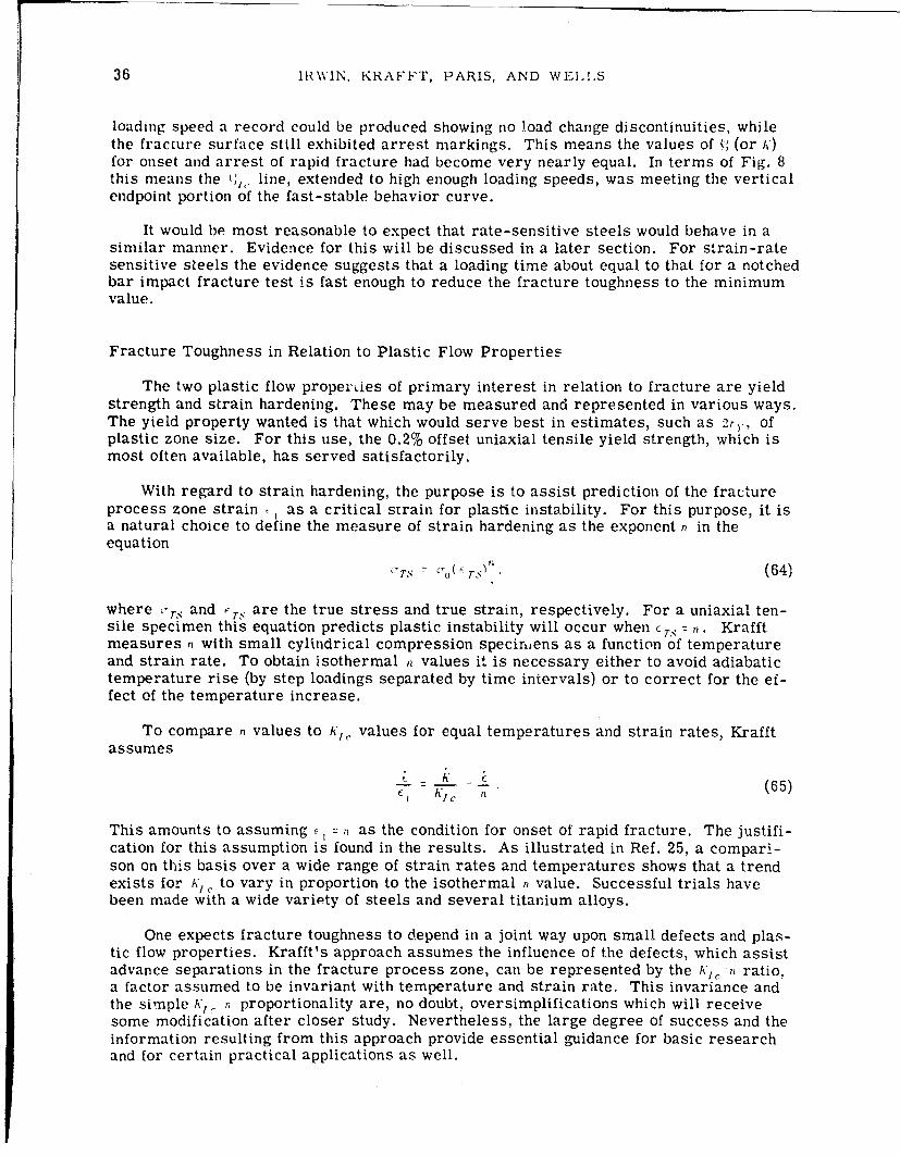
36 IRWIN, KRAFFT, PARIS, AND WELLIS
loading speed a record could be produced showing no load change discontinuities, whilethe fracture surface still exhibited arrest markings. This means the values of •; (or A,)for onset and arrest of rapid fracture had become very nearly equal. In terms of Fig. 8this means the t, line, extended to high enough loading speeds, was meeting the verticalendpoint portion of the fast-stable behavior curve.
It would be most reasonable to expect that rate-sensitive steels would behave in asimilar manner. Evidence for this will be discussed in a later section. For strain-ratesensitive steels the evidence suggests that a loading time about equal to that for a notchedbar impact fracture test is fast enough to reduce the fracture toughness to the minimumvalue.
Fracture Toughness in Relation to Plastic Flow Properties
The two plastic flow properLies of primary interest in relation to fracture are yieldstrength and strain hardening. These may be measured and represented in various ways.The yield property wanted is that which would serve best in estimates, such as 2r,, ofplastic zone size. For this use, the 0.2% offset uniaxial tensile yield strength, which ismost often available, has served satisfactorily.
With regard to strain hardening, the purpose is to assist prediction of the fractureprocess zone strain t as a critical strain for plastic instability. For this purpose, it isa natural choice to define the measure of strain hardening as the exponent n in theequation
rj
"TrS 'o %(!rTS • (64)
where -rS and , TS are the true stress and true strain, respectively. For a uniaxial ten-sile specimen this equation predicts plastic instability will occur when CT n. Krafftmeasures n with small cylindrical compression specir,,ens as a function of temperatureand strain rate. To obtain isothermal n values it is necessary either to avoid adiabatictemperature rise (by step loadings separated by time intervals) or to correct for the ef-fect of the temperature increase.
To compare n values to A*,, values for equal temperatures and strain rates, Krafftassumes
K (65)l KIC n
This amounts to assuming r: as the condition for onset of rapid fracture. The justifi-cation for this assumption is found in the results. As illustrated in Ref. 25, a compari-son on this basis over a wide range of strain rates and temperatures shows that a trendexists for AK . to vary in proportion to the isothermal n value. Successful trials havebeen made with a wide variety of steels and several titanium alloys.
One expects fracture toughness to depend in a joint way upon small defects and plas-tic flow properties. Krafft's approach assumes the influence of the defects, which assistadvance separations in the fracture process zone, can be represented by the A',, n ratio,a factor assumed to be invariant with temperature and strain rate. This invariance andthe simple K1 . n proportionality are, no doubt, oversimplifications which will receivesome modification after closer study. Nevertheless, the large degree of success and theinformation resulting from this approach provide essential guidance for basic researchand for certain practical applications as well.

NRI, REPORT 6598 37
When a series of -7., versus curves are made for a ferritic steel as a series ofdecreasing temperatures, these show regular increases of yield strength with loweredtemperature, but the absolute slopes of these curves after yield are quite similar (49).The same observation can be made for a series of increasing strain rates when adiabatictemperature rise is avoided. Tnis means that, if the , -value measure of strain harden-ing is known for one of these curves, approximate n values for the other temperaturesand strain rates can be estimated on the basis of an inverse proportionality of 7, to yieldstrength. Combining this procedure with the idea of a direct proportionality between K,,and n, this means that, given knowledge of a 7'•. T0 ) measured at the temperature T,), thevalue of /(7T) for the temperature 7' can be estimated from the relation
A y.•.( To)
" 7).S( (66)
The values >., are regarded as 0.2% offset uniaxial tensile yield strengths for thestrain rates pertaining to the A',, tests. Use of Eq. (66) over a very wide range of tem-peratures and strain rates would not serve well, because Krafft's studies show a closerdegree of proportionality of A',,. to n than to (.:-.) - . Trials indicate that Eq. (66) esti-mates of the increase or decrease of i;lr due to ±600F temperature do not show appreci-able error. When the range is extended to ±120'F, the results tend to be moderatelyconservative.
Investigations of c,. for a steel, as a function of temperature and strain rate in therange from very low temperatures to room temperature, can be nearly represented by asingle curve in terms of a speed-temperature equivalence. In fact, Bennett and Sinclair(50) show that data for a variety of metals with crystalline similarity can be fitted to thissame curve by a uniform shift of each curve parallel to the •rs coordinate.
In later sections it will be desirable to estimate uYs for certain rapid strain ratesand at various temperatures from the room temperature static value of c>., * A recentreport by Wessel et al. (51) provided measurements of oys for two large-thickness platesof A302B steel and a plate of rotor steel across the temperature range from -320'F toroom temperature. Using the basic idea in the Bennett-Sinclair paper, a single curverepresentation of this data was made (52). A convenient equation with a good fit to thiscurve was given by the expression
= ý_, J"S ý14. 500 ks - i (67)a" °F,t + - - 0. 4 ksi.(7
T, 1 0 _-o0T+ 459
where 7' is the temperature in degrees Fahrenheit and to is the load rise time for static(slow) testing and is assumed for later purposes to be 50 sec.
To estimate the oy. for a shorter load rise time t the temperature-rate equivalenceidea leads to the relations
Y'S I T, t S ,s ,.,t° (68)
where
T' + t59 log (2. 101o0 ) W'(T+ 159 log (2. 100°to) (
The frequency constant in this equation is adapted from Ref. 50.

38 IRWIN, KRAFF'r, PARIS, AND WELII,S
Equation (67) was written in terms of matching the YS vs temperature curves at-100VF. This is better than matching the curves at 70 F, because it eliminates effectsof strain aging. If the reference temperature is changed to 70'F, the negative term atthe right of the equation becomes -13 ksi. Primarily, Eqs. (67), (68), and (69) are in-tended for use in estimating dynamic yield values at various temperatures in a simpleway. It is not possible to include effects of strain aging without a large increase of com-plexity in the equations. Correspondingly. the tendency of Eq. (67) to predict staticvalues above 00 F, which are somewhat low, was thought not to be harmful.
A recent paper by Shoemaker and Corten (53) suggests that correlation of A',, valuesover a range of temperatures and strain rates might be simplified by going directly to arate-temperature parameter approach as used by Bennett and Sinclair (50) for correla-tion studies of yield strength. Reference 53 notes that an approximate proportionality ofK•,. to n can be implicit in this method and that an n-value-independent relationship ofK,. to ")s can in this way be included.
The most prominent influence of plastic flow properties upon fracture toughness isthe brittle-ductile transition introduced when the crack-tip plastic zone becomes com-parable in size to the dimension of the part parallel to the leading edge of the crack.This was discussed previously. Because of material and testing machine limitations, thecritical K for onset of rapid fracture, which is measured and reported, often containssome elevation above ,'/1 due to plane-stress yielding. If these results correspond to• -- approximate values of A'1, can be obtained-from Eq. (13) by taking
A* A' ( + . (70)
where
(71)
The use of Eq. (70) to predict A,, from a given value of A,,, is subject to a larger un-certainty than its use in the opposite way. However, if :onditions representable as
Sor.. 1 are met, the error of a A', value obtained in this manner should be tol-erable in relation to other uncertainties.
A variety of estimation relationships have been reviewed in this section, becausetheir employment has proved to be useful in checking the general consistency and mean-ing of fracture testing information of many kinds from a variety of sources. Readersshould not infer that these relationships are preferable to possession of the accurate testinformation, the absence of which motivates their use.
Dynamic Fracture Toughness Measurements and FractureTransition-Temperature Tests
Figure 8 shows results of crack arrest observations by Nordell and Hall (54) for1-in.- and 3/4-in.-thick plates of A212B steel. At the NDT of this material, 200F, theplastic-zone size factor ,2r• (plane stress) is about 1/3 in., small enough for the shear-lip borders of the fracture to be small but large enough to allow some plane-stress ele-vation of the A value. The fact that the results show negligible temperature effect below0 0 F may not be significant, because only a small range of temperatures was covered.The upward trend of the crack-arrest A' values above 20°F is due to the approach to mid-range fracture transition conditions expected at about 85'F.

NRL REPORT 6598 39
These results may be compared to an estimate of a rapid load A/,. from the small-flaw drop-weight impact tests used to find the NDT value for the plate material.
The critical section for the fracture produced in nil-ductility transition (NDT) test-ing is shown in Fig. 9. The bar is broken in drop-weight impact bending with a notchedbrittle weld on the tensile side to serve as a representative small flaw. In the originalconcept the NDT separated the temperature region in which a flat break occurred fromthe higher-temperature region in which noticeable plastic bending accompanied separa-tion. In the course of test development and standardization it was convenient to make useof the rapid increase in tendency for arrest of lateral cracking, with increase of temper-ature, through the region of the NDT. Thus, stops were used under the bar, which madethese arrests positive, and the failure or success of arrest is critical to the test result.However, in the analytical interpretation it is best to return to the original idea.
As the specimen bends, the notched, brittle weld bead produces a small part-throughstarting crack. If propagation of this crack occurs prior to yielding at the tensile sur-face, the quick motion of the crack causes separation without noticeable plastic distor-tion. At temperatures from 10°F to 30cF above NDT tests with the stops removed haveshown that plastic bending does occur. At the NDT the stress level for crack propaga-tion is very nearly , the dynamic yield stress for the, plate material. By making afixed arbitrary estimate of the size and shape of the small starting crack, use of theequation for a semielliptical surface crack, as indicated on Fig. 9, gives the result
A/,, =0..79 n.7 (72)
---- 3.5 IN.- - - - - -.
N4IOR IuN.0
0.8IN. O2IN.
K 2 I.2r 0.2 a ~ 1(+2EX-0.2f2 ( ar)2o =. C
.ys
0.Yd
O'YS x 0.2
AT NDT, KId '0.78 ri-Nad
Fig. 9 - Fracture sectionof NDT test specimen
Examination of typical fractured NDT specimens (by G. Irwin and P. Puzak at NRL)suggested that dimensions, approximately as shown in Fig. 9 could be justified in termsof hesitation lines seen on the fracture surfaces. These dimensions might be adjustedmoderately, butl the magnitudes given lead to A, values which are, so far, consistent withother experimental evidence. The result from Eq. (72) is a K1,. value. However, it mightbe helpful to have a special designation for the dynamic -crack-arrest or rapid-loadingA values, which are considered to represent minimum fracture toughness of the materialat the testing temperature. The suggested designation is A'/ I.

40 IRWIN, KRA:FF"T, PARIS, ANI) Wt'II ,S
The room temperature ,, for the material of Fig. 8 was reported as 36 ksi. As-suming a loading time of 0.5 msec for the NDT tests and a loading time of 50 sec forstatic (slow) measurement of-,, use of Eqs. (67), (68), and (69) results in , = 60.4 ksiat the NDT, which was 20"F. Thus, the prediction from Eq. (72) becomes
i 0. 7- M (00. 1) ku 7
1•7.,1 k k (73)
The values of ., for 0.75-in. and 1.0-in. plates were, therefore, 0.81 and 0.61, respec-tively. Using Eq. (70) to estimate the toughness elevation due to plane stress yieldingresults in K values of 65 ksi \7mn- for 0.75-in. plates and 58 ksi qJ1iY for 1.0-in. plates.These values agree with the tests results in Fig. 8 somewhat better than might be ex-pected, particularly since neither the Nordell-Hall calculations nor the estimates devel-oped here for comparison have an accuracy likelihood greater than about 10% in the Kvalue.
At the Materials Research Laboratory (Richton Park, Ill.) measurements by Riplingand Crosley are in progress with the objective of KA,, determinations using rapid hydrau-lic loading and a tapered double-cantilever specimen. The procedure employs a rapid-loading surge superimposed on a moderate initial tension on the specimen. Figure 10shows a set of results which were informally available in October 1966, for specimens ofA302B steel. The estimate of K1" 1 from NDT was uncertain, because results of directNDT testing of the material were not available. From the yield strength and the fact thatthe material was from a large-thickness plate, an NDT of 20cF was selected for com-parison purposes. The estimate of KA' for this choice of NDT is 70 ksi %7i-nI Assuminginverse proportionality of K,• to yield strength provided the lower dashed curve of Fig.10. The measured results lie not far above this curve.
140
DATA FROM MATERIALS RESEARCH LAB.
120-
I00---
- -
80 0"S-. Kid FROM NDT 50'F
"-ONE CRACK ARRESTOBSERVATION OF K
60
TIME TO FRACTURE
4 0 I I I I , , 105 5 20 50 200 500 2000
TIME (MILLISECONDS)
(01 8 - 2IN., On - I N. A 3028 STEEL(0) B I IN., Bn - O.75 IN. 0 8 T CryS " 65.7 ksi(W) 8 1IN., B,- O.51N.
Fig. 10 - Rap-d load A'/,. values from face-notcheddouble-cantilever specimens (Ripling and Crosley)

NRI. REPORT 6598 41
To consider whether the specimens were of adequate size, values of 2% (planestress) are needed. At 0.5 msec load rise time. the value of ', is estimated as 85.5 ksi.With A/,, estimated as 74 ksi % in-. at 70' F, the value of A' based upon H = 2 in. for 700Fis 81 ksi \fT. From this, the value of -,r, (plane stress) is 0.29 in. At 50 msec loadrise time 'r, (plane stress) has increaoed tG 0.38 in. Assuming the net section thicknessshould be three times -rr for adequate conbtraint, the size of the 2-in.-thick test speci-men used in the Ripling-Crosley tests was marginal. However, the specimen size isclose to that desired, and the results correspond to expected behavior relative to loadingtime. Thus, some con'idence can be placed in estimating the 70'F value of i',l as about74 ksi \1_f.
Several crack arrest even!ts were noted during the tests discussed above. Only forone of these was the loicý ior crack arrest indicated clearly enough to permit a calcula-tion. The resu!. w, this single arrest trial provided a k1,, value of 70 ksi TFin.
Figure 11 shows A',,, values estimated for HY-80 steel at the NDT (-150°F), at NDTplus 600 F, and at NDT plus 120'F. Fragments of comparison data were available fromLehigh University (55) and (informally) from Krafft. The experiments at Lehigh Univer-s y were tests of a wide, 1.75-in.-thick ship-steel plate. The test plate contained arectangular, welded insert of HY-80 steel in line with the crack starter slot for a trial atcrack arrest. At 0°F one trial gave a successful arrest. In a second trial, with thecrack much longer at the arrest position, the HY-80 steel separated with a ductile frac-ture, and no arrest was observed. Rough estimates,-of the minimum KA value for crackarrest in the first trial were possible. The conversion to A',, gave the value 135 ksi\f ý. as a minimum estimate, and this is shown in Fig. 11.
140C
A
120 - S0
K 0"
100- NDTK
80[
"• 60
HY-80 STEEL
O',s (M F) = 82 ksi40- NDT - -150' F
20-
o, I I l I_ _-&00 -400 -300 -200 -100 0 100
TEST TEMPERATIJRE(F)
Fig. 11 - Fra-ture toughnesse.stimates for HY-8O steel

42 IRWIN, KRAFFT, PARIS, AND WEI,I,S
Krafft's measurements of A'/,., indicated by the symbol h' in Fig. 11 were with slow-speed loading at -320 ,F. An n coefficient estimate of the static A',,r at -220°F was avail-able and is shown as the point s in Fig. 11. The short vertical line to the right of s indi-cates the temperature at which -,,I for HY-80 would be expected to equal th- static sat -2200F. Thus, the estimate of A',,j from the point S is in close agreement with tneestimates of A,1 ,i from the NDT measuremcnt. Results of a direct measurement of NDTfor the material used in 'he Lehigh Universiiy tests were not available.
The toughness indic-_(ed by the crack- -rest trials discussed above is encouraging.A room-temperature fracture toughnes. F. , 140 ksi if-i-. may be required for afracture-safe, 12-in. -wall-thickness, n,- • , ,ctor pressure vessel. This would seemto be obtainable with steels having a to' .ness ;uality similar to HY-80.
A variety of crack arrest tests have been employed for crack toughness evaluationled by work of this nature by Robertson at the Admiralty Construction and Repair Estab-lishment. These are well summarized by Tipper (56). Generally, the procedure consistsin rapid application of wedge-opening forces to a sharp notch in the specimen. The notchregion is chilled to a low enough temperature for brittle fracturing. The balance of thespecimen may be held at a fixed gradient of temperature rise. Alternatively, the tem-perature of test portions of the plate may be placed at a series of uniform temperaturesin a sequerce of tests. Variations of superimposed tension permit finding a relationshipbetween the machine tensile load and the temperature ior successful arrest of the crack.Although, in concept, a fracture mechanics analysis of these tests might be used to de-termine the A' value for crack arrest, the testing plans do not provide for control andmeasurement of the applied forces to a degree adequate for such calculations. Crudeestimates of the wedge-opening forces for certain SOD (Standard Oil Development) testsof 3/4-in. ship-steel plates were made by Wells (57), and values of K (for crack arrest)were found which agiee roughly with those of Fig. 8.
By standardization of lateral test dimensions and restriction of testing to a limitedrange of plate thicknesses, crack arrest tests have served quite usefully for comparativeassessments of crack toughness. The recommendations therefrom regarding safe rangeof operating temperature are generally similar to those from NDT testing.
The test most used for assessment of fracture toughness on a transition-temperaturebasis is the V-notch Charpy test. So much information has been collected in this formthat an attempt at their use for A'1, estimates seems desirable even though the founda-tions for such estimates are far from ideal.
The definition of V-notch Charpy transition temperature wiiich seems best for analy-sis purposes is the FATT, the temperature at which the side border shear regions occupyhalf of the fracture surface. Use of a test result corresponding to greater brittleness,say the 12-ft-lb temperature, seems undesirable, because this is known to depend uponnotch sharpness and shifts to considerably higher temperatures when a fatigue crack isused at the notch root. The energy level in regions less sensitive to notch sharpness canbe used in terms of an analysis suggested by Wells (15). This provides a plausible KAtype ,ostimate but one which is too far from plane-strain to permit use of Eq. (70) to de-rive a value of K1 ,•. The fracture appearance itself is not truly indicative of relativeplastic-zone size, because the run of the crack is too short relative to specimen thick-ness and does not permit the shear-lip development which would be found in a long cracktraversing an equal-thickness plate of the same material.
Two facts which appear useful are as follows.
I. The V-notch Charpy FATT corresponds generally to a 50% shear-fracture ap-pearance for a low-velocity crack in steel plates of 3/4-in. or 1-in. thickness. By as-suming ý, r for each of these two thicknesses, the proportionality of A',,, to GYd can beestimated using Eq. (70).
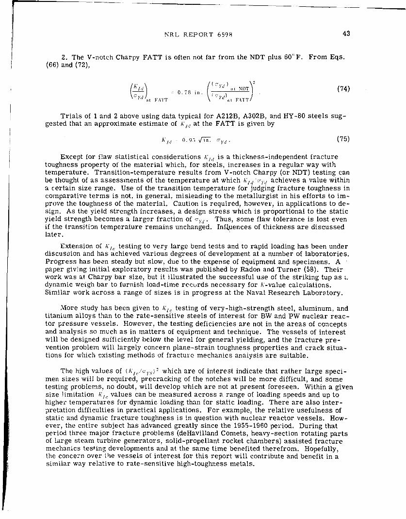
NRL REPORT 6598 43
2. The V-notch Charpy FATT is often not far from the NDT plus 600F. From Eqs.(66) and (72),
= 0.78 in. ( t (74)
, F:'Tr \ 'd), FATT"/
Trials of 1 and 2 above using data typical for A212B, A302B, and HY-80 steels sug-
gested that an approximate estimate of A'/, at the FATT is given by
hA', N 0. 95 (75)
Except for flaw statistical considerations :'1,d is a thickness-independent fracturetoughness property of the material which, for steels, increases in a regular way withtemperature. Transition-temperature results from V-notch Charpy (or NDT) testing canbe thought of as assessments of the temperature at which Ku ',, achieves a value withina certain size range. Use of the transition temperature for judging fracture toughness incomparative terms is not, in general, misleading to the metallurgist in his efforts to im-prove the toughness of the material. Caution is required, however, in applications to de-sign. As the yield strength increases, a design stress which is proportional to the staticyield strength becomes a larger fraction of a,,. Thus, some flaw tolerance is lost evenif the transition temperature remains unchanged. Influences of thickness are discussedlater.
Extension of A',, testing to very large bend tests and to rapid loading has been underdiscussion and has achieved various degrees of development at a number of laboratories.Progress has been steady but slow, due to the expense of equipment and specimens. Apaper giving initial exploratory results was published by Radon and Turner (58). Theirwork was at Charpy bar size, but it illustrated the successful use of the striking tup as •.dynamic weigh bar to furnish load-time recurds necessary for A-value calculations.Similar work across a range of sizes is in progress at the Naval Research Laboratory.
More study has been given to A',' testing of very-high-strength steel, aluminum, andtitanium alloys than to the rate-sensitive steels of interest for BW and PW nuclear reac-tor pressure vessels. However, the testing deficiencies are not in the areas of conceptsand analysis so much as in matters of equipment and technique. The vessels of interestwill be designed sufficiently below the level for general yielding, and the fracture pre-vention problem will largely concern plane-strain toughness properties and crack situa-tions for which existing methods of fracture mechanics anaiysis are suitable.
The high values of (A',%.sy 2 which are of interest indicate that rather large speci-men sizes will be required, precracking of the notches will be more difficult, and sometesting problems, no doubt, will develop which are not at present foreseen. Within a givensize limitation K,, values can be measured across a. range of loading speeds and up tohigher temperatures for dynamic loading than for static loading. There are also inter-pretation difficulties in practical applications. For example, the relative usefulness ofstatic and dynamic fracture toughness is in question with nuclear reactor vessels. How-ever, the entire subject has advanced greatly since the 1955-1960 period. During thatperiod three major fracture problems (deHavilland Comets, heavy-section rotating partsof large steam turbine generators, solid-propellant rocket chambers) assisted fracturemechanics testing developments and at the same time benefited therefrom. Hopefully,the concern over 'he vessels of interest for this report will contribute and benefit in asimilar way relative to rate-sensitive high-toughness metals.

44 IRWIN, KRAFFT, PARIS, AND WEI.I.S
Comments on Crack Opening Dislocation Measurements
In previous comments attention was drawn to the analytical usefulness of the smalllength factor :,. This is perhaps better called "crack opening dislocation" than "crackopening displacement." The former term has been used at times by Wells and avoidsconfusion with crack opening measurements at other positions than the actual leadingedge of the crack. If a sharp fatigue crack is used at the leading edge of the crack-representing notch in the specimen, some slow crack growth cannot be avoided, even un-der plane-strain conditions. Thus, it is not clear how a direct measurement would cope,vith the gauge-positioning problem. In addition, there would be the normal irregularitiesoi the fracture surface.
In trials of direct measurement of > (59) attention was given primarily to rate-sensilive structural-grade steels, and the leading portion of the notch was a jeweler'shacksaw cut, with no fatigue crack extension. It can be argued that under conditions ofmoderate ductility the notch sharpness would not cause a significant difference in thefracture load. Static testing was used, and the temperature range covered did not go farbelow the region of plane-stress to plane-strain fracture transition. At these lower tem-peratures the. ' value, of the order of 10-, in., became comparable to the limits of meas-urement prec'sion. The strain-rate sensitivity and the notch sharpness tended to sup-press slow crack growth, and the hacksaw cut provided smooth surfaces for the gauge.For these reascns, the results of Ref. 58 are of special value from a model-testing view-point. `,
The results verified that the condition for onset of rapid fracturing could be charac-terized by a critica -opening dislocation value x,, which was a function of temperatureand degree of plane-.stress. Aside from considerations of elastic constraint, S, did notdepend upon the dimensions of the crack and the'specimen. Comparison of wide-plateand bend tests permitted examination of the accuracy with which 5ý could be estimatedfrom the plastic bend angles of bars which were too small to prevent general yieldingprior to fracture.
The preceding ivork is summarized in Ref. 15. A more recent review, which alsocontains additional applications of the ) concept in fracture testing, is provided in a cur-rent paper by Wells (60). In this paper Wells derives a method for estimating (1, fromthe energy-loss measurement of a Charpy impact test. Of special interest is Wells'comment regarding a relationship of , to thickness reduction. He reports that Burdekin(BWRA) studied more than 78 measurements of o in comparison to thickness reduction(just beneath the notch) and found they were equal to within a standard error of 20%.
Assuming > equal to the thickness reduction, the latter should be about 0.013 in. fora steel with A 200 ksi N1h7 and 7Y. = 100 ksi. In the temperature range 200° F to 500°Fvalues for Klc YS of 2 \fýiii or more would be expected for a steel similar in toughnessto HY-80. The corresponding thickness reductions would be easily measurable with aprecision greater than the fracture-toughness variations inherent in the material. Aftersuitable testing experience methods of correlation should be possible permitting the useof such measurement results to provide approximate values of fracture toughness interms of A,1 ,. (as well as in terms of 6,).
Comments on Load Toughening and Strain Aging.
Various testing experiences have indicated that a steel pressure vessel, preloadedto a given pressure at a warm temperature, will not fracture appreciably below thatpressure if subsequetly tested at a cold temperature (61,62). Trials of this nature,using precracked tensile specimens. by Br.cthers and Yukawa (63) and by Srawley (NRL),gave a similar indication on an average basis. The scatter of these results might not

NRL REPORT 6598 45
encourage absolute confidence in warm preload strengthening relative to low-temperatureservice. Krafft has noted unexpectedly large values of A',r in rapid-load A',• testing foroccasional specimens which had been accidentally preloaded at a slow speed, presumablythe same effect as the influence of warm preloading.
Since the nuclear reactor vessels of interest will be used at elevated temperature, itwould seem that the warm preload would primarily assist a successful proof test. How-ever, if the preload is done at a temperature well above the service temperature, and ifthe strengthening by crack blunting is verified by a 70°F proof test, confidence in thewarm preload strengthening is merited. Fvrthermore, a substantial advantage relativeto fracture safety during service can be obtai.ned. Sonic monitoring during the preload-ings might indicate locations of previously unseen flaws. In addition, the cracks shouldbe more visible to ultrasonic inspection after the preloadings than before, and a rein-spection at that time would be advantageous.
Room-temperature notched bend test fractures of mild steel (64) were observed toshow a segment of sudden brittle fracture if they were precracked and then left unloadedovernight. No such indication of local embrittlement was found when the specimens werebroken within an hour or so of the precracking. Observations of this kind are not un-common, and the embrittlement is considered to be from the influence of strain aging.In the tests discussed in Ref. 64, brittle fracture segments did not appear at lower loadsthan those used for precracking. However, in fracture trials directed toward K1, testing,Turner (at Imperial College, University of London) found that a specimen, with a notchwhich had been compressed at room temperature, broke at -40OF with a KIo value ofabout the magnitude observed for crack arrest in similar mild steels. In this case thestrain aging occurred after compression normal to the fracture plane, and some residualtensile stress was present.
Tests by Mylonas at Brown University and his "exhaustion of ductility" conceptstimulated several British investigations of compressive prestrain damage. Tipper (56)showed that a substantial portion of the compressive-strain embrittlement effect is notdue to residual stress by applying 10% compressive plastic strain to a large block oflow-carbon structural steel, from which Charpy specimens were later made and tested.When the fracture plane was normal to the direction of compression, the results showeda substantial increase of transition temperature. The original toughness was restored bystress-relief heat treatment. It seems significant that fracture planes parallel to thedirection of compression showed only a relatively small increase of transition tempera-ture.
Although steels differ in their strain-aging tendencies, a significant influence onfracture toughness would not be expected for plastic strains less than 3 times the yieldstrain, regardless of material or fracture-plane orientation. General yielding of thisorder, say at the throat section of a pressure vessel nozzle, would not be harmful, unlessa crack was already present. A substantial amount of strain aging would, then, occur inthe local regions close to the leading edge of the crack. During unloading the materialclosest to the leading edge receives some reverse plastic straining in compression.Thus, a greater damage is expected if the strain aging occurs mainly after rather thanbefore unloading.
A question of interest relating to thick-walled nuclear reactor pressure-vesselsafety concerns wf.ether an abnormal fatigue or stress-corrosion crack growth should bee::pected due to strain-aging embrittlement. Answers to this question should be soughtexperimentally. The crack growth per cycle observed experimentally could be comparedto the size of the crack border strip, in which substantial amounts of reverse plasticstraining are predicted by analysis (65).

46 IRWIN, KRAF'FT, PARIS, AND WELILS
FRACTURE CONTROL PLANS
Comments on Elimination and Slow Growth of Defects
Among the cracks or sharp reentrant notches present in a large structure, after ini-tial inspections and repairs, a single remaining "worst flaw" would be difficult to select.Granting that all cracks could be clearly "seen," a substantial number might appearcomparably dangerous, because of judgment uncertainties which would require dispro-portionate time and new information for settlement. Real inequalities would undoubtedlyexist. However, even if the real inequalities were small, stable crack growth duringservice would tend to develop large diffhrences in crack size. Due to the high power of h,controlling stable crack extension, small differences of size and growth rate are contin-ually amplified so that, eventually, comparatively few cracks emerge as obvious "worst"defects. From service fracture examinations it is clear that there is never more thanone winner of this growth race, because the fracture of the structure can always betraced back to a single origin.
Clearly elevation of the initial fracture strength by the location, grinding out, andrepairing of cracks has certain practical limits. Removal of the huge cracks found byinspection is obviously necessary and helpful. In the smaller range of crack sizes.questions about the necessity of repair arise which depend upon a number of considera-tions. At some point the possible damage introduced by the repair practice itself be-comes a limiting factor.
The reliability of the structure is greatly improved by improvements in the claritywith which cracks and localizations of impurities are seen by inspection techniques.This reduces the seriousness of the worst remaining overlooked defects and permitssensible decisions regarding repairs. However, even if all cracklike defects wereclearly seen, there would be a barrier to improvement of assured strength in terms ofjudgment uncertainties. In this regard, consideration can be given to methods of usingthe amplifying effects of slow-stable crack growth to increase the efficiency of the over-all inspection process. inspections during and after proof testing would be of this nature.
if each defect were labeled with some measure S of the limiting strength, which itwould impose at the end of .\'. hours of service use, the frequency of s would increaseregularly with S. Lnspection, repair, and trial loadings must give assurance that thevalue of S,,.,) for the very worst defect is above the strength so required in service.This means that S, in(.\) for X at the beginning of operational use must be well above s,because the defects tend to move to smaller s values with increasing hours of service.
The level of the smin Y,(.) which can be regarded as assaired by initial testing and in-spection tends to reduce with increase of structural size. In part, this is simply inherentin the probability aspects. In addition, the size and variety of initial defects, prior to in-spection, tend to increase with the size and complexity of the structure. Periodic struc-tural inspections, as in the case of commercial aircraft, are very helpful to fracturecontrol. In this practice, one is able to use the amplifying effectE of stable crack growthto assist identification of the most serious cracks. The periodic inspection type of con-trol is most reliable when stress corrosion is not of serious importance. After a crackbegins to extend with a corrosive type of assistance, the time to the failure point islikely to be less than the period between inspections. Because of uncertainties involvedin crack-growth-rate prediction, extension of a fracture control plan to a larger struc-ture is somewhat easier than extension of the plan to a larger value of "L,
Service fractures due to stress-corrosion crack extension are sometimes observedin which a segment of fatigue cracking from the initial flaw preceded the extension withcorrosion assistance. Under steady loads with water or salt water environment, naturalcracks produced by fatigue seem to possess a threshold K value below which the corro-sive effect does not induce measurable crack extension. Crack extension rates above
NRI, lR EBOR1T 6598 47
this level are rarely studied. Most testing is in terms of total time for the crack toreach propagation size. However, the long times pertain to initial K values which do notexceed the critical K(... by an amount which would be significant in reference to lnrgenuclear reactor pressure vessels.
The situation need not be all one of disadvantage regarding water corrosion effects.The tough steel selected for use in very large nuclear reactor pressure vessels shouldbe chosen to have a K/.(.. (for water environment) not far below the value of A',,. In thisevent, with initial, much lower, A' values established by careful quality control, the lead-ing edges of prior cracks might be static long enough for a corrosion-assisted bluntinginfluence to aid continued resistance to crack growth.
Notes prepared for this report by Professor A. A. Wells (Queen's University, Bel-fast) contained the following comment: "The records of insurance companies in theUnited Kingdom seem to show that service failures in steam and chemical pressure ves-sels have mainly occurred as a result of definite accidents or excursions, such as fail-ures of safety valves or of feed water supplies. A relatively thin (1/2 in.) refrigerantvessel dissected after 24 years service, after which the vessel was condemned becausecracks had been found (presumably because of improved NDT techniques), showed blackoxidation that must have arisen during welding, over the whole of every cracked surface.There was no evidence of crack extension during service. The vessel had not beenstress relieved, and it was fractured at the end of its life at a pressure marginally abovethe hydrostatic test pressure. This single example drawn from the proportionally largepopulation of these vessels may help to explain the deart- of other examples of crackgrowth during normal boiler service."
The preceding comment was intended to be used only with due caution relative tothick-walled pressure vessels of higher-strength steel in a radiation as well as waterenvironment. No doubt the routine 50% overload customarily used in proof testing Brit-ish boiler and refrigerant-type pressure vessels does tend to blunt the prior cracks, andthe dissected vessel might be a more successful Pxample than others. For nuclear pres-sure vessels allowance for whatever slow crack growth seems credible must be retainedin the fracture control plan. However, the ideas available tend to generate interest inexperimental data applicable to the steels to be used in the pressure vessels under con-sideration. Slow crack growth is of critical importance to fracture safety in this appli-cation. and the factS, when known, may show the slow-stable crack growth problem ismuch smaller than a conservative judgment can accelnt at the present time.
Fracture Safety in Relation to Crack Arrest
The difficulty of arresting relatively iarge cracks in thin-walled pressure vesselswas recognized and extensively studied in connection with the unfortunate fuselage explo-sions experienced by de Haviland commercial jet aircraft in 1954 (66). The criticalcrack size for sheet material similar to the high-strength aluminum-alloy fuselage cov-ering was less than the size of a window opening at the stress level expected for 35,000ft altitude, even in a flat sheet. Due to inadequate window reinforcements, a small fatiguecrack could deve!op near a corner of a window and, with its effective size enhanced bythe poorly stiffened window opening, could attain critical size for propagation before aninspection was likely to reveal its presence. In the investigations following the planelosses a number of such small fatigue cracks were developed at windows during flightsimulating tests of additional Comet fuselages, and the bursting of these test fuselagesoccurred from such cracks in consistency with the above failure sequence.
The emphasis of the Comet-inspired investigations was turned from fatigue towardcrack arrest devices by information from U.S. studies of fracture mechanics (67) coupledwith the following facts. During the history of passenger aircraft aviation the discovery

48 IRWIN, KRAFFT, PARIS, AND WEILS
of small fatigue cracks during overhaul has never been uncommon. The de HavilandComet fuselage sheet material was similar in toughness to the USA 7075-T4 aluminumalloy. Previous airplane material experience both in England and in the U.S. was pri-marily with the much tougher 2024-type aluminum alloy. When the 7075-type materialis used in place of the 2024-type material at the same percentage of the yield strength,the combined influence of higher working stress and less toughness is nearly a factor of10 in terms of critical crack size for crack propagation. The fatigue crack growth rateis increased rou~ghly by a factor of 6 for equal-size cracks. Clearly, the safety of pas-senger planes prior to 1954 depended more upon overhaul inspections and upon the longservice life necessary to grow very large fatigue cracks to critical size, than upon elim-ination of fatigue cracking.
In the 1953-1957 period (at NRL and NACA) the stresses for propagation of given-size cracks in flat sheets of plastics and high-strength aluminum were compared to thecritical hoop membrane stresses in cylindrical sections of these materials containingsimilar-size axial cracks and subjected to internal pressure. The stress elevating in-fluence of outward bulging of the crack section (due to the internal pressure) was quicklyrecognized. The effect increased with crack length. By using a lubricated (and strong)cylindrical cover over the cracked portion of the test cylinder, the nominal hoop stressfor crack propagation in the cylinder could be made the same as the nominal stress onthe flat-plate specimen in tension, for the same size crack. No effort was made at de-tailed stress-analysis explanations of this special aspect of cracking behavior. However,the magnitude was so large (as much as a factor of 10 in effective critical size) that theoutward bulging effect on propagation of long cracks in pressure vessels has been con-sistently emphasized in NRL technical papers (42,67,68). For the arrest of a long crackin a pressurized container by a riveted stiffener, an arrangement which would provide alocal "flat sheet" situation, as well as a stiffener-induced reduction of the stress field,.was recommended (67).
A number of U.S. investigations of bursting strength of containers damaged withvarious-length through-cracks have shown the long-crack bulging influence discussedabove. Thus, the results of U.K.-AEA tests, as reported by Nichols (69), were not unex-pected. One cannot, of course, accept 6-in.-long to 12-in.-long cracks in a 1-in. wallthickness as modeling 6-in.-long to 12-in.-long cracks in a substantially larger (3 to 12in.) wall thickness. The increase of effective crack size due to local bulgng would bemuch larger for the 1-in. wall thickness and would be expected to dominate the test re-sults. In addition, the modeling would be poor, because of differences in elastic con-straint of the crack.
A fail-safe crack-arresting fuselage design is heavier than one which is not so de-signed. However, there is some saving in added weight, because the customary designprovides strong hoop-direction frames. Thus, when skin attachments to hoop-directionstiffeners are used to arrest longitudinal cracks, the frames, customary to the design,may be satisfactory for this purpose, except for spacing and the positioning of flangesadjacent to the skin.
In modern jet passenger aircraft, through the use of tough (2024-type aluminum) skinmaterial and suitable attachments to frames (or hoop straps), it is possible to arrestcracks with lengths which are several hundred times the thickness of the fuselage wallunder service conditions of internal pressure. In case of an accident starting such acrack, the crack would certainly bulge open, and maintenance of a low-altitude pressurein the cabin might be impossible. However, the structure would be safe enough for op-eration of the airplane to a safe landing. This type of fail-safe crack-arrest design ispeculiar to the nature of the aircraft fuselage structure.
A thick-walled steel pressure vessel built for internal liquid pressure containmenthas no natural reason for hoop direction stiffeners. Furthermore, for the vessels of

NRI, REPORT 6598 49
interest to this report, through-cracks could not be allowed to reach a length hIargeenough for appreciable outward bulging, because this would permit very rapid escape ofliquid and hot vapor. The addition of massive external rings at spacings of about twoplate thicknesses would certainly improve the wall strength, particularly if these ringswere installed so as to exert external pressure on the cylinder wall. Primarily, the goalof a fail-safe scheme of this kind would be to suppress outward bulging of the cylinderwall along the region of any long through-crack (in a longitudinal seam weld, for example)and to provide enough strength to support the hoop-tension load in the event of such acrack. After some years in service the amount of remaining compression under therings would be uncertain, and crack arrest under the ring would rest on too small amargin of stress difference to deserve any confidence.
The large-scale fracturing of welded ships was blamed in part upon the continuityintroduced by welding which permitted a crack to run directly, without reinitiation atrivet holes, from one large plate into the adjacent plates. Separation of longitudinalrows of deck plates with an overlapping riveted connector has been employed with somesuccess as a crack arresting device. A "tough strip" crack-arresting device for thesame purpose has been proposed. In this plan the riveted connector is not used. Instead,the deck plates are joined by welding to a connector of very-high-toughness material,such as HY-80 steel; in either case, successful crack arrest depends upon the stressfield force driving the crack, which increases with crack length. Given a large enoughstress field force, any crack arrestor will be unsuccessful. The unsuccessful crack-arrest trial with an HY-80 crack arrest strip previously discussed, merely indicated theA',, for HY-80, at 00 F, was less than 200 ksi Tiin.
If we regard the pressure vessels of this report as welded regions connected byarresting wall material, the most dangerous regions would be along segments of longi-tudinal welding and along welds joining the nozzles to the pressure-vessel wall. A con-servative crack-arrest plan would be to provide sufficient toughness so that cracks com-pletely through the metal affected by welding would be stable at the expected servicestress level. In addition, this crack length would need to be small enough so that theeffect of outward bulging near the crack due to internal pressure was small or negligible.Further study of this second requirement is needed. However, we can assume that acrack length as small as twice the plate thickness would be small enough for that pur-pose. To satisfy the first requirement, the maximum lengths of such cracks must be incorrespondence to the equation
"/< 2 C(76)
The crack length is 2a. Assuming conservative design (stresses well below yield) andKi, = 170 ksi i i-., a 2-ft-long crack in a 12-in.-thick vessel wall would be stable atstresses below 20 ksi.
Use of ring-rolled cylindrical sections to eliminate longitudinal seam welds washelpful to the fracture strength of steel chambers for solid propellant rockets. Continuedconsideration of this construction method for application to large BW and PW nuclearreactor pressure vessels seems desirable for purposes of point of view, even if the ringsare not solid forgings. The cylindrical portion of the vessel would then consist of ringsjoined by girth welds, as at the present time. However, the rings, if not solid forgings,would have been plant-welded. inspected, and heat treated to such a high quality levelthat the welded regions could be regarded as possessing the required crack-arresttoughness.
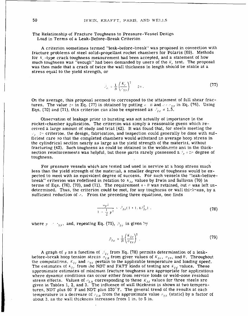
50 IRWIN. KRAFFT, PARIS, AND WELLS
The Relationship of Fracture Toughness to Pressure-Vessel DesignLoad in Terms of a Leak-Before-Break Criterion
A criterion sometimes termed "leak-before-break" was proposed in connection withfracture problems of steel solid-propellant rocket chambers for Polaris (69). Methodsfor K,, -type crack toughness measurement had been accepted, and a statement of howmuch toughness was "enough" had been demanded by users of the A' test. The proposalwas then made that a crack of twice the wall thickness in length should be stable at astress equal to the yield strength, or
__ (K 2 2r.(77)
On the average, this proposal seemed to correspond to the attainment of full shear frac-tures. The value 2- in Eq. (77) is obtained by putting a - i) and -, -- 7,. in Eq. (76). UsingEqs. (70) and (71), this criterion can also be expressed as '.= 1.5.
Observation of leakage prior to bursting was not actually of importance in therocket-chamber application. The criterion was simply a reasonable guess which re-ceived a large amount of study and trial (42). It was found that, for steels meeting the
,2- criterion, the design, fabrication, and Inspection could generally be done with suf-ficient care so that the completed chambers would~withstand an average hoop stress inthe cylindrical section nearly as large as the yield strength of the material, withoutfracturing (42). Such toughness as could be obtained in the weldnle..ts anri in the thick-section reinforcements was helpful., but these parts rarely possessed a 2-;- degree oftoughness.
For pressure vessels which are tested and used in service at a hoop stress muchless than the yield strength of the material, a smaller degree of toughness would be ex-pected to meet with an equivalent degree of success. For such vessels the "leak-before-break" criterion was redefined in relation to A',, values by Irwin and Sullivan (70) interms of Eqs. (76). (70), and (71). The requirement a -B was retained, but c was left un-determined. Thus, the criterion could be met, for any toughness or wall thi,ý'ýess, by asufficient reduction of Y. From the preceding three equations, one finds
"Y (I÷ I :,l )- ,1(78)
.I y2
where y - and, repeating Eq. (71), ,/ is given r,/
A graph of y as a function of from Eq. (78) permits determination of a leak-before-break hoop tension stress @j.q from giver values of A,/, a'., , and B. Throughoutthe computations. K•" and -r pertain to the applicable temperature and loading speed.The estimates of A',, from the NDT and FATT kinds of testing are Ai'd values. Theseapproximate estimates of minimum fracture toughness are appropriate for applicationswhere dynamic conditions can occur either from service loads or weld-zone residualstress effects. Values of c-,18 corresponding to these K/d values for three steels aregiven in Tables 1, 2, and 3. The influence of wall thickness is shown at two tempera-tures, NDT plus 60'F and NDT plus 1200F. The general trend of the results at eachtemperature is a decrease of c. from the approximate value vy, (static) by a factor ofabout 3, as the wall thickness increases from 1 in. to 5 in.

NRL REPORT 6598 51
Table 1HY-80 Steel, (700F) = 82 ksi and NDT= -150°F
Estimated Dynamic * 1 -H Static ValuesValues (in.) Stati c (ksi)Valu
At -90°F 1 0.912 0.693 84•-.•=94 ksi
"= 122 ksi 2.5 0.364 0.358 44
A1, = 116 ksi ,fT• 5 0.182 0.243 30 = 94/3 = 31 ksi
At -30' F 1 1.25 0.88 9988 ksi
= 113 ksi 2.5 0.50 0.44 50
126 ksi N fiiZ 5 0.25 0.289 33 3 • = 88 /3 = 29 ksi
Table 2A302B Steel, = 62 ksi and NDT 0°F
Estimated Dynamic j 3 1 JValues (in.) _ I Yd - ,( I)
At 60OF 1.0 0.809 0.630 52= 63 ksi
•Yd = 82.7 ksi 2 5 0.324 0.333 28
K•d 74.4 ksi 4TiF 5.0 0.162 1 0.229 19 3 = 21 ksi
At 120°F 1.0 1.03 0.761 59I s= 60 ksi
')w = 77.8 ksi 2.5 0.413 0.388 29
5.0 0.206 0.260 20K'1 1 = 79.1 ksi 1T 8 0.,2 03 = 20 ksi
8.0 0.129 0.202 16
Table 3A212B Steel, cy.= 36 ksi and NDT = 20°F
Estimated Dynamic B LBValues (in.) *
21c Yd (ksi)
At 80 OF 1.0 0.835 0.647 36
"=55.9 ksi 2.5 0.334 0.340 19 36 ksi
51.1 ksi 1-fT-Y 5.0 0.167 0.232 13 Cs'3 = 12 ksi
At 140°F 1.0 1.29 1.10 (55) Yl,ý = 33 ksi
.= 50.1 ksi 2.5 0.518 0.451 23
hK1,, 57.0 ksi %Tn 5.0 0.259 0.293 15 3 = 11 ksi

52 IRWIN. KRAFFT, PARIS, AND WELLS
When a fracture-safe operating range is defined in terms of NDT plus 60'F orFATT, such a criterion should be regarded as a general-experience-based rule. It tendsto be conservative for wall thicknesses less than 1.5 in., but this conservatism wouldoften be needed. With an increase of will thickness, the design would be more cautious.Stress relief of 5-in.-wall vessels would be expected. Estimates of allowable stress fordynamic crack instability conditions, as shown in the tables, can be formally developedfrom the fracture -mechanics-based equations, without regard for experience. However,consideration of factors specific to the individual application is necessary in their use.
The leak-before-break criterion, in , = 2-. form, did not appear to be conservativein its application to ultrahigh-strength steel rocket chambers, despite the iact that .'ý C -'-
corresponds to a large degree of plane-stress toughening. Very careful design, fabrica-tion, and inspection were required even when the toughness criterion was satisfied. Inthat application the problem of controlling slow crack extension due to stress corrosionduring hydrotesting was seriously underestimated. Very few fractures occurred belowdesign stress in firing trials. Elimination of crack growth due to stress corrosion dur-ing hydrotesting would have been most helpful.
The :;.C values in the tables are well below ihe value necessary for tough plane-stress fracturing. Certainly, for vessels with walls more than 2.5 in. thick, fracturesafety in the past has depended much more upon conservative design stress than upon thetoughening influence of a brittle-ductile fracture transition.
With reference to thick-walled nuclear reactor pressure vessels, the influence oftemperature elevation in terms of the degree of plane-stress toughening is gradual andnot very large. No support can be found on that basis for a step-function-type diagramof limiting allowable load, based upon a critical temperature. The allowable-load dia-gram suggested by this study would be one of gradual increase with temperature to thepoint where decrease of yield stress with temperature was a limiting consideration. Thecomputation might be made using Eq. (78). However, a simpler plan can be suggested asfollows. Available K'C data for steels over a wide temperature range can be fitted, to afair approximation, assuming a simple direct proportionality brtween K',, and the abso-lute temperature. Thus, if a decision has been reached on the temperature T, at whichoperational pressure is allowable, a straight line on a load-temperature graph from thatpoint to zero load, at absolute zero temperature, would provide a safe, allowable loaddiagram for temperatures below 7'T. Practices currently used would be applicable attemperatures above T,.
A fracture of a glass rod or plate normally occurs from a small surface flaw, and ahalf-circle mirror region can be seen at the fracture origin. This outlines the shape ofthe crack front when the crack speed reached the limiting velocity, and efforts at crackdivision began to roughen the fracture surface. Similar half-circle crack-front shapeshave been observed in other brittle solids, even when the crack depth is large and thestress on the section reflects some bending.
With regard to the leakage aspect of the leak-before-break analysis, a half-circlewould be the expected shape for a crack deepening from one surface into the wall of anuclear reactor pressure vessel in all regions where the stress is well belr g the staticyield strength. As the surface length approaches 2R, the stress elevation in the net sec-tion beneath the crack would tend to cause relatively fast severing of that part. Thus,the average length of the crack parallel to the wall after breakthrough and ctart-of-leakage should not exceed 2B.
In the nozzle throat section the stress favors development of a longitudinal crack ina plane containing the axis of the nozzle, starting at an inside corner. The crack frontwould have an approximate quarter-circle shape. It seems likely that a leak-before-break design stress would permit arrest with completion of a through-crack on one side
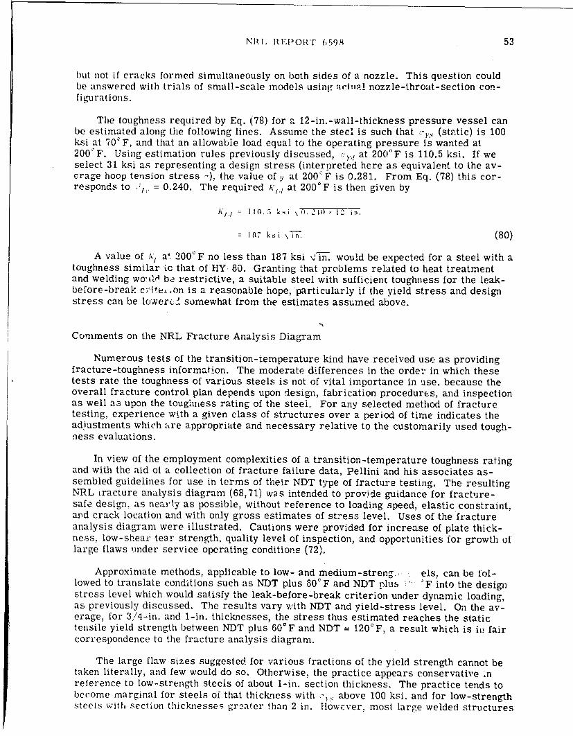
NRI. Rt'uiOTr ,598 53
but not if cracks formed simultaneously on both sides of a nozzle. This question couldbe answered with trials of small-scale models using actual nozzle-throat-section con-figurations.
The toughness required by Eq. (78) for a 12-in. -wall-thickness pressure vessel canbe estimated along the following lines. Assume the steel is such that (. (static) is 100ksi at 70'F. and that an allowable load equal to the operating pressure is wanted at200'F. Using estimation rules previously discussed, -Yd at 200°F is 110.5 ksi. If weselect 31 ksi as representing a design stress (interpreted here as equivalent to the av-erage hoop tension stress 4-), the value of y at 200'F is 0.281. From Eq. (78) this cor-responds to ., = 0.240. The required A,,, at 2000F is then given by
K d, I ! 0..; k i \ 0. 2U, W 12 in.
18- k si \%i-. (80)
A value of A'/ a' 2000F no less than 187 ksi .jin. would be expected for a steel with atoughness similar to that of HY 80. Granting that problems related to heat treatmentand welding wo-.tW be restrictive, a suitable steel with sufficient toughness for the leak-before-break c-ite,:,on is a reasonable hope, particularly if the yield stress and designstress can be lowverc& somewhat from the estimates assumed above.
Comments on the NRL Fracture Analysis Diagram
Numerous tests of the transition-temperature kind have received use as providingfracture-toughness information. The moderate differences in the order in which thesetests rate the toughness of various steels is not of vital importance in use, because theoverall fracture control plan depends upon design, fabrication procedures, and inspectionas well as upon the toughness rating of the steel. For any selected method of fracturetesting, experience with a given class of structures over a period of time indicates theadjustments which are appropriate and necessary relative to the customarily used tough-ness evaluations.
In view of the employment complexities of a transition-temperature toughness ratingand with the aid of a collection of fracture failure data, Pellini and his associates as-sembled guidelines for use in terms of their NDT type of fracture testing. The resultingNRL iracture analysis diagram (68,71) was intended to provide guidance for fracture-safe design, as nearly as possible, without reference to loading speed, elastic constraint,and crack location and with only gross estimates of stress level. Uses of the fractureanalysis diagram were illustrated. Cautions were provided for increase of plate thick-ness, low-shear tear strength, quality level of inspection, and opportunities for growth oflarge flaws under service operating conditions (72).
Approximate methods, applicable to low- and medium-streng, els, can be fol-lowed to translate conditions such as NDT plus 60°F and NDT plus " •F into the designstress level which would satisfy the leak-before-break criterion under dynamic loading,as previously discussed. The results vary with NDT and yield-stress level. On the av-erage, for 3/4-in. and 1-in. thicknesses, the stress thus estimated reaches the statictensile yield strength between NDT plus 60°F and NDT = 120'F, a result which is it! faircorrespondence to the fracture analysis diagram.
The large flaw sizes suggested for various fractions of the yield strength cannot betaken literally, and few would do so. Otherwise, the practice appears conservative inreference to low-strength steels of about 1-in. section thickness. The practice tends tobecome marginal for steels of that thickness with c- , above 100 ksi. and for low-strengthsteels with section thicknesses greater than 2 in. However, most large welded structures

54 IRWIN, KRAFFT, PARIS, AND WELLS
are designed for stresses well below the yield stress, and, often, the service loads areessentially static. Hence, a large degree of success from using the fracture analysisdiagram would be expected and has been experienced.
Relative to the thick-walled pressure vessels of interest in the report, a major hand-icap in using the method, is that the NDT measurement points for the tough steels ofprincipal interest lie too far below the range of temperatures for service operations. Asimilar handicap would pertain to all of the presently customary methods of toughnessevaluation in terms of a transition temperature.
There is also a scarcity of A,,, data for high-toughness steels, except at low tem-peratures. Although higher-temperature, large-specimen data of the A'/, type should beavailable soon, fracture toughness information from direct measurement for high-toughness steels, at temperatures above 200'F, will probably require completion ofsuitable testing plans based upon one of the plasticity analysis viewpoints previousiydiscussed.
Proof Test Estimates of Critical Crack Size in Relation toFracture Safe Life
The first interesting question concerns what can, be deduced from the fact that aproof test with internal pressure is successfully completed. Estimates will be madehere on the basis of a semielliptical surface crack with a depth one-quarter of the sur-face length of the crack. The equation for A" in relation to depth 7, tension and tensileyield strength 7's is
S3.7 a (81)1 . t9 -0. 212 (c'c~)
As!7 lming A302B steel, rs (static, 70 0 F) = 60 ksi, and NDT = 100 F, the estimates ofu~a and A',, at 70°F are 79.8 ksi and 71.5 ksi NT1- Suppose the design stress is 24 ksiand the proof test produces an average hoop tension in the wall of the cylinder portion of1.25x24 ksi = 30 ksi. Using these data in Eq. (81) a crack size given by a = 2.2 in. wouldhave become unstable at a stress level of 30 ksi. This calculation is on a dynamic basis.On a static basis we assume
A' IC (static) 71. 5 ksi \i -n.60
7 95 ks i 'tn.
The new estimate of the crack size, shown to be absent by proof testing inspection, isgiven by a = 5.2 in. Cracks of about 40% greater depth and smaller surface length wouldbe estimated using a semicircle crack shape. Larger cracks could be present if therehad been a crack-blunting treatment by warm prestressing. The amount of that size in-crease would be uncertain and would depend upon the degree of confidence in crack-blunting effect of the warm prestressing.
With regard to regions of the nozzle where the stress is locally elevated, it will beassumed that an additional plastic strain equal to the yield strain occurs across the re-gion containing thc crack. When the stress level in this region first achieves 60 ksi ten-sion across the crack, the dynamic basis estimate of the critical size is obtained from

NRL REPORT 6598 55
3.77 (60)2a (82)1.49-0.212 (60/80)2
or
7 - 0.52 i~i.
it would, of course, be inconsistent to assume that continued straining occurs if such acrack is present and is resisted only by the dynamic fracture toughness. On the otherhand, to assume a smaller crack and add the influence of plastic strain to the openingdislocation ý, amounts to crack blunting, arid an onset of fast fracture instability cannotbe certainly predicted. An increment of stable extension comparable to ý is more likely.
The critical crack size estimates for base metal cylindrical portions of the vesselwere unreasonably large and can be viewed as incredible. However, if the local of thesecalculations are shifted to a longitudinal weld and if the fracture toughness is assumed,in K -value terms, to be less by 30%, the critical crack sizes are then reduced by a factorof 2. The dynamic calculation estimate then becomes 1.1 in., which is small enough fora significant probability of existence. Furthermore, a weld which joins a nozzle to ashell is subject to some superimposed bending stress to a degree dependent upon the ef-ficiency of the design. Increasing the tensile stress 30% would also halve the sizes ofthe cracks judged to be critical.
The preceding calculations are, of course, no moreqthan illustrative. For good frac-ture control each vessel should be studied in terms of the stress analysis, fabrication,and property data applicable to that vessel.
We consider next the critical crack sizes which would be required for failure underoperating conditions. For simplicity we assume that the operating pressure is appliedat 700F. We also assume the hoop tension developed is 0.8x24 ksi = 19.2 ksi. To keepthe crack sizes within reason we use the reduction by a factor of 2, suggested above. Wethen find the critical crack size (dynamic) has increased from 1.1 in. to 2.7 in.; and thecritical crack size (static) has increased from 2.6 in. to 4.7 in.
Using these sizes, calculations based upon the maximum fatigue crack growth rates,as discussed earlier, indicate tnat 107 or more cycles are needed for fatigue to increasecrack growth to unstable size. If an allowance of an additional facto:' of 2 for 30% in-crease of stress is made, the critical crack sizes are reduced and the growth rate isgreatly increased. However, the required number of cycles is still above 104.
In the nozzle regions where plastic straining occurred during proof test and wherethe stress may be about 60 ksi under operating conditions, an estimate of the above kindis not possible. A'reasonable guess at crack growth rate could be made. However, thereis no clear way to fix the initial maximum crack size so that the number of growth incre-ments can be estimated. It is quite possible that residual compressive stress from theproof test may provide adequate protection of such regions of highest strain.
The possibility for crack growth to critical size by stress corrosion, in any regionof the vessel, must be considered on a different basis. It is, in fact, not possible toguarantee safety relative to moisture-assisted slow growth of the maximum-size surfacecracks, unless the material and the cracks are such that a "below KISCO" situation is al-ways maintained.
Present information gives no positive indication that water plus steady tensioncauses slow crack growth in A302B vessels, except for conditions of fatigue. The waterinfluence was already represented for fatigue by using the highest growth rate constantc., from a previous sectien of this report. Additional investigations of A302B and of can-didate steels for future vessels are necessary relative to water-environment stress-corrosion crack growth. Evidence exists that h'KIc can be increased by crack blunting.

56 IRWIN, KRAFFT, PARIS, AND WELLS
In the present application a substantial degree of crack blunting exists, possibly enoughso that this type of stable crack growth need not be a matter of concern.
In the case of the A302B steel vessel discussed in the preceding illustration, thewall thickness was not specified. If the vessel is required to satisfy leak-before-breakconditions in the terms of this section, then the value of !/ = '7LB C',d is given by
- - 0.a08 . (83)79.8
The corresponding value of 3,, from Eq. (78) is 0.281. Thus,
= 0.281 = (L79.8 (84)
and B = 2.76 in.
The small value of B is in part due to stress level and, in part, due to the use of K',,rather than a static K,,. If the stress level is reduced from 24 ksi (design) to 19.2 ksi(operating), B becomes 4.46 in. The thicknesses ccrresponding to these two stress lev-els, if the static A', is assumed, are 8.14 in. and 13.9 in. Using the dynamic toughnessestimate K,,, the 19.2-ksi wall stress would be below the calculated ILB for an 8-in. wallthickness of the assumed material, at temperatures above some temperature in theneighborhood of 2600F. The nuclear reactor termed Palisades is an example in whichthe operating pressure is too high for the leak-be'fore-break criterion only in the low-temperature range.
This duscussion cannot propose to settle such questions as whether the leak-before-break criterion should be used or, if so, whether on a dynamic or on a static basis. Theprimary purpose is to illustrate ways in which such questions can be discussed usingmacroscopic fracture analysis methods.
Radiation Effects Relative to Fracture Properties and =p1B
Curves of true-stress against true-strain for HY-80 steel, after various neutron ex-posures, were shown by Chow and McRickard (73). These curves shift upward with anincrease of irradiation in much the same fashion as they would do with a decrease intemperature or an increase in strain rate. In the case of similar curves for A302B steel(74) the radiation hardening is accompanied by a decreasing trend in the slopes of thecurves. Bearing in mind an approximate proportionality of KI> to the strain-hardeningexponent n these results suggest that a greater influence of irradiation embrittlementwould occur for A302B than for HY-80 under the conditions of irradiation which wereemployed. The above authors estimated the irradiation temperature at 30'C. Measure-ments of the increase of NDT by Steele and Hawthorne (75) for irradiation temperaturesbelow 450°F provide results in the direction indicated by the strain-hardening behavior.
Previously, attention was directed to th6 fact that very small defects of the typewhich interfere with easy glide of dislocations, and thus have major importance to plasticflow properties, tend to influence fracture primarily in an indirect manner through theireffect on the plastic flow properties. The defects introduced by radiation are quitesmall, and it is probable that most of their influences upon fracture toughness can beunderstood in terms of modification of plastic flow properties. An exception would needto be made for grain boundary weakening due to He (76).
For irradiation below 5x 10 "• n/cm 2 (<1 MeV), assumed here to be the region ofmajor interest for the walls of large BW and PW nuclear reactor pressure vessels, the

NRL REPORT 6598 57
stress-strain curves of irradiated steels seem to possess a normal appearance, indicat-ing that Kid estimates along the lines used previously can be employed after irradiationto the same degree as before.
The aspect of major interest is the tendency of an increase of -YS to accompany anincrease of NDT and is best understood in terms of an illustration. As before, the steelis A302. The data were collected by Steele, Hawthorne, and associates (75,77) usingmaterial from a 6-in.-thick plate using neutron exposures at temperatures below 2500F.A graph was made of NDT as a function of ay, (static, 0.2% offset, 700F) from measure-ment results obtained after irradiation, The increase of o-., per 1000F elevation of theNDT was 12 ksi up to 1 x10 19 n/cm 2 (<1 MeV) irradiation, where the NDT had become230'F. The overall slope corresponded to 15 ksi per 1000F change of the NDT acrossthe range up to 8 x 10' 9 n/cm2 irradiatio.i.
The undamaged properties were NDT = 100 F and ay, (static, 700F) = 67 ksi. Esti-mates of the dynamic yield elevation to obiain CrYd and estimates of Kid as 0.78 Nfin. 0 rdgave the results shown in Table 4. The values in parentheses were formally obtainablefrom the estimation procedure, but the irradiation dosage might be high enough to re-quire a different analysis treatment.
Two methods of estimating the fracture oughness radiation damage for NDT = 2300Fare (a) estimating K d at 10°F for the undamzged material used to estimate Kid at 2300Fundamaged using the idea of a direct proportionality between R'id and the absolute tem-perature and (b) estimating Kid (undamaged) a, 2300F oh the basis of inverse proportion-ality to dynamic yield strength. Method (b) would underestimate the damage effect,because the temperature range is too large for this method. Method (a) gave Kid (un-damaged, 2300F) = 136 ksi \ Thus, the damage influence was a K-value loss of 47%.Method (b) indicated a smaller amount, 307c. Thus, a substantial damage to fracturetoughness occurred. It is notable, however, that the elevation of NDT by irradiation isaccompanied by an increase of Kid at the NDT.
This aspect was explored additionally by estimating CrLB at NDT plus 600 F. Valuesof CrYd and i, d, were calculated for each of the three NDT-plus-600 F temperature points.The results are shown in Table 5. Apparently, the increase of 0 yd which accompaniesincrease of NDT is high enough to enable a nuclear :eactor pressure vessel, which didnot initially meet a leak-before-break operating pressure criterion at NDT (or NDT plus600 F), to reach such a condition a!.ter substantial radiation damage.
Table 4 Table 5A302B Steel, B = 6-in. Wall Thick- A30211 Steel, B = 6-in. Wall Thick-
ness, aY, Static, 70°F = 67 ksi neso, a,", Static, 70°F = 67 ksi
T TSPlus 60F Kid L(0F) V(ksi) di) (ksi Pls-6) (ksi) (ksi F-i.) (ksi)
10 67 92.5 72.1 70 86.8 76.0 19.6230 100 108.7 84.8 290 105.9 87.1 20.0
425 134 (134.7) (105) 48.5 (133.7) (106) (24.4)
The estimates of C1B based upon dynamic fracture toughness are normally moreconservative than those based upon static fracture toughness. The tensile stress-straincurves for A302B steel after various amounts of irradiation, given in Ref. 77, have anincreasing abnormality toward "negative strain hardening" in the dosage range above0.8x 1019 n/cm 2 . This suggests tha.t the static K,, would be seriously lowered by the
58 IRWIN, KRAFFT, PARIS, AND WELLS
increased tendency toward plastic instability. The "unhardening" behavior is expected tobe time-dependent and may not occur fast enough to have an equally strong influenceupon NDT and V-notch Charpy tests.
Static Au"c measurements were made at Bettis Atomic Power Laboratory, usingA302B steel and various amounts of irradiation at levels above 1011 n/cm 2. These wereinformally discussed with the author. Estimating back from KA,, values based upon NDTafter elevation to 230°F and to 4250F, the room-temperature Kid should be about 60 ksiN5[n. However, the static measurements are much less than this at room temperature.In the approach of test temperature toward NDT, the static measurements tend to in-crease rapidly. The size of the test specimen did not permit great confidence in thesehigher values. A portion of this increase might be from plane-stress yielding. However,the fracture-toughness value approached at NDYT would not have exceeded the KId esti-mate at NDT in any case.
Granting that more experience may be necessary with K,, measurements ofradiation-damaged steels, it seems probably that, beyond some dosage limit, a conserva-tive calculation of fracture strength may depend more upon the static KIC value than uponthe dynamic value. This aspect has only recently appeared and requires careful investi-gation.
REFERENCES
1. Rankin, A.W., and Moriarty, C.D., "Acceptance Guides for Ultrasonic Inspection ofLarge Rotor Forgings," ASME paper 55-A-194
2. DeForest, D.R., Schabtach, C., Grobel, L.P., and Seguin, B.R., "Investigation of theGenerator Rotor Burst at the Pittsburgh Station of Pacific Gas and Electric Co.,"ASME paper 57-PWR-12
3. Irwin, G.R., "Notes for March 24, 1959, meeting of ASTM Committee in New Yo-.K,'(ORNL Library and NRL Mechanics Div. have copies)
4. Irwin, G.R., "The Leading Edges of Fracture Mechanics," ASME Thurston Lecture1966, ASME Trans (forthcoming)
5. Wells, A.A., "The Mechanics of Notch Brittle Fracture," British Welding Res. Vol.7 (Apr. 1953)
6. Wells, A.A., and Post, D., "The Dynamic Stress Distribution Surrounding a RunningCrack," Trans. SESA 16(No. 1):93 (1958) (Discussion by G. R. Irwin)
7. Irwin, G.R., "Fracture Dynamics," in "Fracturing of Metals" (ASM Symposium 1947)ASM Cleveland (1948), pp. 147-166
8. Orowan, E., "Fundamentals of Brittle Behavior of Metals," Symposium on Fatigueand Fracture of Metals, New York:Wiley, p. 139, 1952
9. Clark, A.B.J., and Irwin, G.R., "Crack Propagatio, Bphavior,-" Exp. Mech. (June1966)
10. "Fracture Toughness Testing and Its Applications," ASTM Spec. Tech. Publ. 381(1965)
a. McClintock, F.A., and Irwin, G.R., "Plasticity Aspects of Fracture Mechanics,"pp. 84-113

NRL REPORT 6598 59
10. b. Paris, P.C., and Sih, C.C., "Stress Analysis of Cracks," pp. 30-83
c. Tiffany, C.F., and Masters, J.N., "Applied Fracture Mechanics," pp. 249-277
d. Srawley, J.E., and Brown, W.F., Jr., "Fracture Toughness Testing Methods,"pp. 133-198
e. Kies, J.A., Smith, H.L., Romine, H.E., and Bernstein, H., "Fracture Testing ofWeldments," pp. 328-356
11. Irwin, G.R., "Crack Extension Force for a Part-through Crack in a Plate," Trans.ASME 29E:651 (1962)
12. Irwin, G.R., "Plastic Zone Near a Crack and Fracture Toughness." 7th SagamoreOrdnance Materials Res. Conf., Aug. 1960, Proc. publ. by Syracuse Univ., 1961
13. Irwin, G.R., "Fracture Mode Transition for a Crack Traversing a Plate," Trans.ASME 82(No. 2):417-425 (1960)
14. Clark, W.G., Westinghouse Research Lab. report, forthcoming. (Results reportedat ASTM E-24, Sub. I, Mtg. June 1966)
15. Wells, A.A., "Notched Bar Tests, Fracture Mechanics and the Brittle Strengths ofWelded Structures," IIW Houdremont Lectuare, British Welding J. 12:2 (Jan. 1965)
16. Barenblatt, G.I., Advan. Appl. Mech. 7:55 (1962). (There were previous papers by
Barenblatt in Russian Journals.)
17. Dugdale, D.S., J. Mech. Phys. Solids 8:100 (1960)
18. Bilby, B.A., Cottrell, A.H., and Swinden, K.H., Proc. Roy. Soc. A 272:304 (1963)
19. Irwin, G.R., "Fracture Mechanics Applied to Adhesive Systems," in "Treatise onAdhesion and Adhesives," R. Patrick, editor 1:254 Dekker (1967)
20. McClintock, F.A., and Hult, J.A.H., Proc. 9th Int. Congress on Appl. Mech. (Brus-
sels, 1956) Vol. 8, p. 51
21. Walsh, J.B., and Mackenzie, A.C., J. Mech. Phys. Solids 7:247 (1959)
22. Koskinen, M.F.., Trans. ASME 85D:585 (1963)
23. Rice, J.R., "The Mechanics of Crack Tip Deformation and Extension by Fatigue,"Brown U., Div. of Eng. Report, May 1966
24. Rice, J.R., "Stresses Due to a Sharp Notch in a Work Hardening Elastic-PlasticMaterial Loaded by Longitudinal Shear," Brown U., Div. of Eng. Report, Dec. 1965
25. Krafft, J.M., Appi. Mater. Res. 3:88 (Apr. 1.964)
26. Williams, J.G., and Turner, C.E., "The Plastic Instability Viewpoint of Crack Prop-agation," Appl. Mat. Res. 3:144 (1964)
27. Krafft, J.M., "Role of Local Dissolution in Corrosion-Assisted Cracking of TitaniumAlloys," Report NRL Progress, Mar. 1967, p, 8
28. Johnson, H.H., and Willner, A.M., "Moisture and Stable Crack Growth in a HighStrength Steel," Appl. Mater. Res. 4(No. 1):34 (Jan. 1965)

60 IRWIN, KRAFFT, PARIS, AND WELLS
29. Paris, P.C., "The Fracture Mechanics Approach to Fatigue," in "Fatigue - An In-terdisciplinary Approach," Syracuse University Press, p. 107, 1965
30. Donaidson, D.R., and Anderson, W.E., "Crack Propagation Behavior of Some Air-frame Materials," Proceedings of the Crack Propagation Symposium, Cranfield,England, Sept. 1961
31. Paris, P., and Erdogan, F., "A Critical Analysis of Crack Propagation Laws,"Transactions of A.S.M.E., J. Basic Eng., Series D, 85(No. 4) (Dec. 1963)
32. Brothers, A.J., and Yukawa, S., "Fatigue Crack Propagation in Low-Alloy Heat-Treated Steels," Transactions of ASME, in J. Basic Eng., Paper No. 66-MET-2 (tobe published, 1966)
33. Carman, C., and Katlin, J.. "L, Cycle Fatigue Characteristics of High StrengthSteels," Transactions of A.S.M.E., J. Basic Eng., Paper No. 66-MET-3 (to be pub-lished, 1966)
34. Clark, W., and Wessel, E., private communication of data on A302B steel (Westing-house Research Laboratories)
35. Piper, D., Smith, S., and Carter, R., "Corrosion Fatigue and Stress CorrosionCracking in Aqueous Environment," A.S.M. National Metal Congress, Oct. 31, 1966
36. Crooker, T., Morey, R., and Lange, E., "Low Cycle Fatigue Crack Propagation inQuenched and Tempered Steels Under Corrosive Environments," NRL Report 6196,Sept. 1964 (See also subsequent-quarterly reports of Metallurgy Division of NRL)
37. Crooker, T., and Lange, E., private communication of data on A302B steel (NRL)
38. Wei, R.P., Talda, P.M., and Li, C.Y., "Fatigue Crack Propagation in Some Ultra-High-Strength Steels," Proceedings of the ASTM Fatigue Crack Propagation Sympo-sium, 1966 (forthcoming)
39. Brown, B.F., "A New Stress-Corrosion Cracking Test Procedure for High-StrengthAlloys," Mater. Res. Std. (ASTM), 1965 (See also subsequent NRL Reports by Brown,et al.)
40. Rolfe, S.T., Novak, S.R., and Gross, J.H., "Stress-Corrosion Testing of UltraserviceSteels Using Fatigue Cracked Specimens," presented at the Symposium on StressCorrosion Testing, ASTM, in Atlantic City, New Jersey, June 27-28, 1966
41. "Fracture Testing of High-Strength Sheet Materials; a Report of a Special ASTMCommittee," ASTM Bulletin (No. 243):29 (1960)
42. Irwin, G.R., "Structural Aspects of Brittle Fracture," Appl. Mater. Res. 3:65(Apr. 1964)
43. Sternberg, E., and Sadowsky, M.A., "Three-Dimensional Solution for the StressConcentration Around a Circular Hole in a Plate of Arbitrary Thickness," J. Appl.Mech. 16:27 (1949)
44. Wundt, B., informal communication
45. Harris, D.O., and Dunegan, H.L., "Fracture Toughness of Beryllium," Trans. ASTM(forthcoming)

NRL REPORT 6598 61
46. Ripling, E.J., Mostovoy, S., and Patrick, R.L., "M,.asuring Fracture Toughness ofAdhesive Joints," Mater. Res. Std. 4:129 (Mar. 1964)
47. Mostovoy, S., and Riphng, E.J., J. Appl. Polymer Sci. 10:1370 (1966)
48. Yoffe. E.H., "The Moving Griffith Crack," Phil. Mag. 42:739 (1951)
49. Smith, R.L., Moore, G.A., and Brick, R.M., "Mechanical Properties of Metals atLow Temperature," Proceedings of the NBS Semicentennial Symposium, 1951.Washiington:Govt. Print. Off., 1952
50. Bennett, P.E., and Sinclair, G.M., "Parameter Representation of Low TemperatureYield Behavior of Body Centered Cubic Transition Metals," ASTM paper 65-MET-11,1965
5i. Wessel, E.T., Clark, W.G., and Wilson, W.K., "Engineering Methods for the Designand Selection of Materials Against Fracture," Westinghouse Res. Lab. Rpt. to ArmyTank-Automotive Center, June 24, 1966
52. Irwin, G.R., "The Leading Edges of Fracture Mechanics," ASME 1966 Thurston Lec-ture, Trans. ASME (forthcoming)
53. Corten, H.T., and Shoemaker, A.K., "Fracture Toughness of Structural Steels as aFunction of the Rate Parameter, T 1. g (A,, ') ," ASME paper 66-WA/MET-8 (1966)
54. Nordell, W.J., and Hall, W.J., "Two Stage Fracturing of Welded Mild Steel Plates,"Univ. of Ill. Report, Curl Eng. Dept., Oct. 1963
55. Gerridge, D.W., and Slutter, R.G., "The Brittle Behavior of High Strength SteelWeldments," Lehigh Univ., Fritz. Eng. Lab. Rpt. 200.61.364.8, Apr. 1965
56. Tipper, C.F., "The Brittle Fracture Story," Cambridge, England:Camb2 Age Univer-sity Press, 1962
57. Wells, A.A., "Strain Energy Release Rates for Fractures Caused by Wedge Action,"NRL Report 4705, Mar. 1956
58. Radon, J.C., and Turner, C.E., "Note on the Relevance of Linear Fracture Mechan-ics to Mild Steel," J. Iron Steel Inst. 204:842 (1966)
59. Burdekin, F.M., and Stone, D.E.W., J. Strain Anal. 1:145 (1966)
60. Wells, A.A., "Fracture Control of Thick Steels for Pressure Vessels," IIW Meeting,Dusseldorf, Apr. 1967
61. Wells, A.A., "Welded Ferritic Stee' Construction for Intermediate Low-TemperatureService," ASTM STP-302, p. 21, 1962
62. Irvine, W.H., Quirk, A., and Bevitt, E., "Past Fracture of Pressure Vessels," J.Brit. Nix'. 7nergy Soc. 3:31 (Jan. 1964)
63. Brot.bercA.A., and Yukawa, S., "The Effect of Warm Prestressing on Notch FractureStreng:..'"" 7.-an.,;. ASME, J. Basic Eng. 85D:97 (Mar. 1963)
64. Irwin, G.R., "Fracture Dynamics," in "Fracturing of Metals," ASM Cleveland, 1948

62 IRWIN, KRAFFT, PARIS, AND WEILS
65. Rice, J.R., "The Mechanics of Crack Tip Deformation and Extension by Fatigue,"preprint No. 36, ASTM Meeting, June 1966
66. De Havilland Official Rep. on "Comet" Failures, 1955
67, Irwin. G.R., Kies, J.A.,. and Smith. H.L.,. "Fracture Strength Relative to Onset andArrest of Crack Propagation," Proc. ASTM 58:640 (1958)
68. Pellini, W.S., and Puzak, P.P., "Practical Considerations in Applying LaboratoryFracture Test Criteria to the Fracture Safe Design of Pressure Vessels," NRLReport G030, Nov. 1963
69. Nichois. R.W., Proc. Roy. Soc. A285:104 (1965)
70. Irw;n, G.R., and Sullivan, A.M., Proc. Roy. Soc. A285:141 (1965)
71. Puzak, P.P., and Pellini, W.S.. Welding J. 35:275-S (June 1956)
72. Pellini, 'Y.S., Goode, R.J., Puzak, P.P., Lange, E.A., and Huber, R.W., "Review ofConcepts and Status of Procedures for Fracture-Safe Design of Complex WeldedStructures Involving Metals of Low to Ultra-High-Strength Levels," NRL Report6300, June 1965
73. Ci.-ýw, T.G.Y., and McRickard, S.B., "Low-Temperature Embrittlement of Iron, IronAlloys, and Steels by Newtron Irradiations," ASTM STP 380:120 (1965)
74. Trozera, T.A., and Flynn, PoW.. ASTM STP 380:342 (1965)
75. Steele, L.E., and Hawthorne, J.R., ASTM STP 380:289 (1965)
76. Earnes, F.S., ASTM STP 380:58 (1965)
77. Steele, L.E., Hawthorno, J.R., Serpen, C.Z., Watson, H.E., and Klier, E.P., "Irradi-ation Effects on Reactor Structural Materials - 1 May - 31 July 1965," NRL Memo-randum Report 1638, Aug. 15, 1965

Appendix A
RECOMMENDATIONS
PROPOSED INVESTIGATIONS AND TE.HNIQUE DEVELOPMENT
la. Investigate material crack paths and , vauc_• for cracks in high-stress regionsat or near a nozzle. Such studies might employ a moDel constructed of a brittle, trans-parent material with stahie crack extensiorn assisted by moisture, or a model constructedof a low-toughness metal with stable crack cxtension produced by fatigue.
lb. Investigate the residual, compressive-stress type of protection which might beprovided to such regio>.ý from the proof-testing method.
2. Develop ull,,, Lsonic techniques appropriate for finding and estimating sizes oft r . ,i , ' 1 " I 1 iS .
0
kutblish control and inspection techniques which insure absence of significantcentt r- line weakness in electroslag weldments.
4a. Investigate stable-water-assisted crack growth rate for steels of interest usingpressures, temperatures, and radiation typical of service conditions.
4b. Study the possibility of suppressing crack growth by means of warm preloadcrack blunting, if this stable growth rate is not negligible.
5. Investigate the influence of loading speed on i',, and on isothermal strain harden-ing in relation to the study of radiation hardening and embrittlement near and above adosage of 10"'" n/cm 2 (<1 MeV). A strong effect on both measurements is probable, dueto the unstable relaxation of hardening (from large amounts of radiation) in the presenceof increasing plastic strain. Time-rate sensitivity in this hardening relaxation would beexpected. The dynamic A',, (or A',,,) may be larger than the static A',, and some revisionof methods for assessing the degree of radiation damage may be necessary.
SUGGESTED TESTS AND THE LEAK-BEFORE-BREAK
CRITERION
1. Large-Thickness Toughness Tests
It is strongly endorsed that sharp notch tests should be performed on the materialsdeveloped for service, over the desired temperature range, at full section thickness.The bend test is favored, in view of its reasonable static load requirement, suitabilityfor impact loading, and convenient comparison with the drop-weight NDT test. However,fatigue notches would he preferred; to obtain clear conditions for fracture mechanicsanalysis, a combi'nation of slow bend tests and impact tests would also be desirable. Itis vital that these tests, both static and dynamic, should be autographically instrumentedfor load, displacement, and either COD or transverse contraction at the notch root.
63

64 IRWIN, KRAFFT, PARIS, AND WEIll,S
2. Intermediate-Thickness Substandard Toughness Tests
It will only be possible to test limited numbers of full-thickness specimens as partof a material evaluation program. Howevei-, Charpy-V specimens may prove to be toosmall for adequate routine production control of toughness at thr; selected level. It isconsidered that the evaluation program should contain half-thickness or quarter-thicknesstests with which a reasonable full-thickness correlation might be obtained using CODmechanics methods. These tests should also be fully instrumented.
3. Small-Scale Local Toughness Tests
It is possible that certain microstructural combinations associated with weldedjoints will give rise to low-toughness zones. If large programs of in situ tests of suchjoints are not to be mounted, there should be an available sampling procedure usingsmall-scale tests of subdivided joints to screen for low-toughness regions. This alter-native is recommended, and it is considered that a small-scale test, such as the pre-cracked Charpy test, should be further developed for the purpose. Instrumentation forautographic recording of load and displacement would be advisable to permit extractionof relevant fracture mechanics data. The same procedure could be used to monitor theeffects of irradiation.
4. Slow Defect Growth and the Hydrostatic Test
It would appear, from studies of fatigue growth rate data and the thresholds forstress corrosion (and creep rupture cracking), that these factors will not be as impor-tant for the thick reactor pressure vessel steels-as they are for high-strength steels andthat slow extension of defects in service will not, therefore, be extensive. In this con-nection, it would seem '.o be more desirable to develop the technique of proof of vesselsat intervals by hydrostatic test than to rely completely upon nondestructive flaw detec-tion in service. The philosophy of proof test would comprise (a) overpressurization atan elevated temperature before repetition at an ambient or low temperature, to minimizethe risk of loss by fracture during proof test and (b) determination of the period of valid-ity of the proof test on the basis of: overpressure factor, or estimated rate of slowgrowth of the defects of toughness deterioration.
5. Full-Scale Vessel Test
If it is decided to test a fi'1l-scale vessel representative of thick material, i, isrecommended that the nozzle/sphere configuration should be employed, since the inter-section region is considered to be the most critical in terms of the presence of crackdefects. The test should be performed under a pulsating pressure tc nucleate a naturalcrack defect at the most critical region, and it should be associated both with periodicapplications of overpressure and measurements of slow growth of flaws, to provide abasis for proof test qualification in service.
6. Leak-Before-Break .7iterion
It is recommended that the leak-before-break criterion of fracture should be re-tained, in spite of the increases in thickness and yield strength of reactor steels, becauseof the extra degree of sensitivity to defect sizes at stress concentrations that wouldotherwise arise. This is regarded as practicable if the precracked Charpy energy levelcan reach the level given by
. 0. 56 (A1)

NRL REPORT 6598 65
hence,
IV 0A16 (A2)It' = 0. 116 9) .3( 2
For A533 steel the maximum thickness is 12 in., and the minimum yield strength is50,000 lb/in.2 ; therefore,
-I = 116 ft -lb.
For A542 steel the maximum thickness is 8 in. and the minimum yield strength is85,000 lb/in. 2; therefore, wI 223 ft-lb. These values are regarded as possible ofachievement.

Appendix B
FRACTURE ANALYSIS UNDER CONDITIONSOF GENERAL PLASTIC YIELDING
GENERAL YIELDING IN A PRESSURIZED CYLINDER WITH ALONGITUDINAL CRACK
An effect which may be important in relatively thin cylinders and spheres concernsthe crack extension force supplement from the bulging effect of internal pressure ia thecrack region. When the crack length is more than M1, experiments have shown substan-tial amounts of bulging. Theoretical analyses by Folias*" suggest that the crack extensionforce (c;) ratios between through-cracks of given length 2a, in shells and flat plates, maybe expressed in the form
(shell) (2 aBSI+q-, -q< .(B)
C](flat plate) ILR •!B
where the constant q is 1.9 for spheres and 1.6 for cylinders. I? is the midthickness ra-dius, and 13 is the thickness. Folias expresses reservations concerning additional termswhich are neglected in the analysis. Nevertheless, the trend is well represented forcracks for which a( im does not greatly exceed 1.
Assume radius R, thickness [?, crack length 2a, internal limit pressure p, and yieldstress c-,., , Consider a beam element adjacent to the slit and parallel to it, lcaded withaxial tension pI? 2 and distributed load 2pa per unit width. The bending moment at eachof the three plastic hinge points is pa 2
.,. but the limiting bending in the presence of ten-sion may also be shown to be
p a 3- ( k2 (B2)
This may be regrouped as follows, in terms of the ratio of the hoop-to-yield stress pie 3-:)and the dimensionless quantity B?'a", the solution of which is given by
_,_ l- Ble [ - I ( L'221 (B3)
and
Sa• a:(134)
At the limit pressure p plastic bending will take the form of bulging deflection, whichwill cause the axial tension to increase. This will diminish the limit moment until astage of membrane longitudinal tension is eventually established, limited in turn only atthe uniaxial yield stress. When this state is reached, there will bf- no remaining capacityto resist shearing in the radial plane at the ends of the crack, and tearing will thereforebe anticipated. Thus, the plastic hinge bending may be established as a true, generalyielding condition for the cylinder. In Table B1 strength factors are compared for thelinear elastic calculation and the plastic limit calculation above.
*E. S. holias, Intern. J. Fracture Mech. l(Nos. 1 and 2) (1965).
66
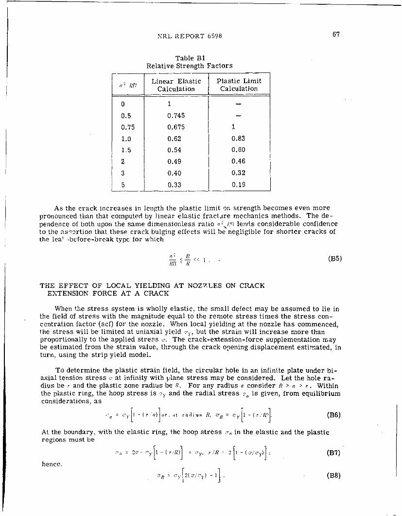
NRL REPORT 6598 67
Table B1Relative Strength Factors
Linear Elastic Plastic LimitCalculation Calculation
0 1
0.5 0.745 -
0.75 0.675 1
1.0 0.62 0.83
1,5 0.54 0.60
2 0.49 0.46
3 0.40 0.32
5 0.33 0.19
As the crack increases in length the plastic limit on strength becomes even morepronounced than that computed by linear elastic fracture mechanics methods. The de-pendence of both upon the same dimensionless ratio oý .V? lends considerable confidenceto the asz-rtion that these crack bulging effects will be negligible for shorter cracks ofthe lea' .before-break typc for which
a-2 < V < (B5)
THE EFFECT OF LOCAL YIELDING AT NOZ7.LES ON CRACKEXTENSION FORCE AT A CRACK
When the stress system is wholly elastic, the small defect may be assumed to lie inthe field of stress with the magnitude equal to the remote stress times the stress con-centration factor (scf) for the nozzle. When local yielding at the nozzle has commenced,the stress will be limited at uniaxial yield Jy, but the strain will increase more thanproportionally to the applied stress ý7. The crack-extension-force supplementation maybe estimated from the strain value, through the crack opening displacement estimated, inturn, using the strip yield model.
To determine the plastic strain field, the circular hole in an infinite plate under bi-axial tension stress c- at infinity with plane stress may be considered. Let the hole ra-dius be r and the plastic zone radius be R?. For any radius a consider Ri > a > r . Withinthe plastic ring, the hoop stress is 7Y and the radial stress o is given, from equilibriumconsiderations, as
L-7=JrY[11 (r'a)]Ior. at radius R, . R ~ ' -Y1 (r ;le' (B6)At the boundary, with the elastic ring, the hoop stress c- in the elastic and the plastic
regions must be
2c,- r- Y1 -( le) = , u* R 2[1 alo C~}.)j (B7)
hence.
= • 2( cl/,.)- (B8)

68 IRWIN, KRAFFT, PARIS, AND WELLS
The hydrostatic stress in the plastic zone is
UY + ,R +0
(B9)+3 3 [2 - (?, (a)
and the deviator stresses are
( [T + (r/a'] / C- [1-(2r,'a)] (B10)
Thus,(7a 2 1-( r,"'a) (BI11)ap 1+(ra)
But, for radial displacement u, e, u,,'a and e = d'u,w'a, so that
_ (( .e ) 3+,, (B 12)c e /da + rr/a)
The solution to this is
.. [1 + (r(B 13)
At the elastic/plastic boundary
-= "E R = +-2 - -)+
so that in the plastic region
C 'Y 2-,,c- a (B 14)CY/\ +-N
or., at the edge of the hole,
Y - (B15)
The ratio between this value and the corresponding value without yielding is given by
9(pIa.Li c) + [( + Z - q -' (_ (B 16)
from which the strain limitation arising from surrounding elastic material is evident,even when the plastic zone has grown to large size. Table B2 gives several values ofinterest for this ratio.

NRL REPORT 6598 69
The COD, hence the crack extension force and the stress field parameter, can beestimated for a radial surface crack of very short length c by assuming that the extent ofthe yield zone is identical with that for the circular opening. The value obtained may becompared with thc ilnear/elastic equivalent
-,( 2Cr) 2 C (B 17)
Now, the strip yield model gives rise to a COD value
8( )"I" (8 )) (B1 8)
whence,
several values of which are listed in Table B3 for cracks of length r/n, from which itwould appear that Eq. (B17) is suitable for calculations for small cracks without correc-tion.
Table B2 Table B3Ratios of Elastic to Plastic Comparison of Linear Elastic
Stress and Strain and Strip Yield Model
0- i-iR e P(pla tic) 2c, R? _'- I? I~ ~ as-iC rGpr ai i r eO(clasti(-) r•-" " - _ _ _ _ 2( a- t i y n 10l n 20=
0.5 1.0 I 1.0 1.0 1.0 0 - - -
0.6 1.2 1.25 1.08 1.2 0.25 0.126 0.516 0.905
0.7 1.4 I 1.67 1.23
0.8 1.6 2.5 1.49 1.4 0.67 0.50 0.785 1.07
1.0 2.0 - 2.8 1.6 1.5 0.60 0.86 1.08
For intermediately longer cracks a first approximation to the crack extension forceis obtained from the alternative assumption that the circumferential plastic strain at theinside edge of the opening is wholly accommodated as crack opening displacement, at apair of diametrically opposite edge cracks. This incremental value of COD is largecompared with the preyield value, and leads to
y = ys K'Trr, ) K' K (B20)
where, from Eq. (B15), k" is given by
K' -i (B21)
w s a u nn e
with several values given in Table 134.

70 IRWIN, KRAFFT, PARIS, AND WELLS
ratio .,. For rate-sensitive materials, the loading speed and the ratio of static-to-dynamic fracture toughhess would be important additional factors. The analysis, at thispoint, faces enough elements of uncertainty so that an appeal to experimental results forguidance would be desirable.
In the case of large nuclear reactor pressure vessels, loading would be slow enough,even in the proof test, to suggest that crack extension would be resisted by the static A1ý .For A302B steel at 70°F onp might assume KA, = 90 ksi J'f:n and . = 65 ksi. Forthese values, a = 0.86 in. would produce onset of rapid fracture when the general tensionacross the region of the crack first reached s.: --- If the crack present is smaller andreaches instability with ,, S , the value of (a is given by
765
or
1.92 in.2. 24 + (,
Selection of q larger than 2.24 would mean-that cracks with values of a less than0.46 in. would produce onset of rapid fracture. For example, if q1 = 4, the critical valueof a is 0.31 in. The relative infrequency of proof test failures at pressures which pro-duce tensile yield at local regions of nozzles, coupled with inspection uncertainties, sug-gests the proper value of q1 is in the range of 2 to 4. A small crack, which achieves avalue of A` .- K2,, during the attainment of general yielding in the region of the crack,is expected to extend only by a stable increment of growth in the balance of the loadingcycle. The unloading cycle would leave this crack in a state of residual compression, acondition likely to protect the crack from additional slow growth. during subsequent load-ings to smaller internal pressure.
WORK REQUIREMENT FOR FRACTURE OF A SHARPLYNOTCHED BAR IN BENDING
From investigations of plastic slip fields by Green and Hundy* the deformation nearthe root of the notch (for nonwork hardening, fully plastic bending) occurs on slip lineswhich are arcs of circles centered beneath the notch at the distance 0.45 1,A" where dN isthe net ligament size. Wells (60) assumes from this result that the value of ýS after sub-stantial bending and a stable crack growth of x is approximately given by
0o.4.1 (d 0 - X) C (B25)
where is the plastic bend angle of the bar, ,i. is the original ligament depth at x = 0,and for elastic strain components, is assumed negligible compared to ,.
"'A.P. Green, and B.B. 1Hundy, "Initial Plastic Yielding in Notch Bend Tests,' J. Mcch.Phys. Solids 4:128-144 (1956).

NRL REPORT 6598 71
Table B4Estimates of A" and A"
A'' A "' 11" A'" A"'
1.0 0.08 0.45 1.4 10.491 1.
1.2 0.23 0.82 1.6 1.8 c jThe larger values A" (Table B4) represent the coefficients obtained if plastic behav-
ior is neglected, but the cracks are assumed to extend between ±ie and are subject to theremote stress field of magnitude uT.
These assessments show that crack extension force values for small radial crackdefects at a nozzle are not significantly greater when plastic deformation occurs at theinner periphery than when it does not.
ALTERNATIVE DISCUSSION OF SMALL CRACK IN A FIELD OFGENERAL YIELD
When the plastic zone at the leading edge of the crack is separated from the freeedges of the specimen by a large linear-elastic domain, the crack opening dislocationis proportional to e; cY through a near-unity proportionality constant. The definition ofemployed in verifying the relationship would be in terms of the integral of y -directionstrains around the elastic-plastic boundary.
After general yielding the same definition is applicable in a formal way. However,after the plastic zone contacts the free edges of the specimen, a simplified method ofanalysis is possible. Consider, for example. the case of a small surface crack in anozzle throat region, where analysis predicts a zone of yielding which is confined but islarge compared to the crack size. The portion of • established prior to general yield ofthis region can be estimated as
(B22)
where c;, is the plasticity adjusted value of Q} corresponding to a general tension acrossthe region equal to 7Y. Beyond this point we assume that the plastic flow pattern aroundthe crack scales in proportion to the crack size and tends to concentrate the effect oftension direction yielding near thf, crack into an increase in S. To represent the influ-ence of a plastic strain equal to cy. 'E, the effect in terms of additional S value might beestimated as
C-y1' q~aT '- (B23)
where q, is a near-unity proportionality factor.
If the surface length of the crack is 4a, the adjusted linear analysis gives
S 2. .24 . (B24)
Whether a , value which would be large enough for onset of rapid fracture in theelastic range will produce more than an increment of stable extension depends upon the

72 IRWIN, KRAFFT, PARIS, AND WELLS
If , retains a critical value b, as x increases, we have the relationship
( df3 0.415 (do -z)dO - 0,.15 Odt - 0. (B26)
Thus, during increase of x
deC 0 dz -x 3 dX (B27)
(d -X) 0,45 (d 0 -(X)B2
The bending moment for a unit-thickness bar which would be consistent with th? basicassumptions is approximately
1 - ' (d _ z)- (B28)
4 0
Calculation of the work in terms of
IV $ 8 M d0 + J Mdo' (B29)
"0 (a-1 Xr=0
gives the result
IV' = 1. 11 C' .6c do (B30)
or1V = 1. 1 L (,• do .(1331)
Wells (60), for reasons not clearly explained, assumes that
dO dz (B32)(0.45) 2 (do -X)
during increase of x and finds that
IV = 1.91 P do 0 (B33)
where w is the total work per unit bar thickness.
Since the intuitive, expected result is I= •) do, the answer with the smaller coeffi-cient appears to be the most acceptable calculation method.
The preceding total fracture work calculation leading to Eq. (B31) suggests that Eq.(B25) might be used to estimate values of , when the fracture of a notched bar occursafter general yielding. A discussion of applications of this idea is given in Ref. 16.
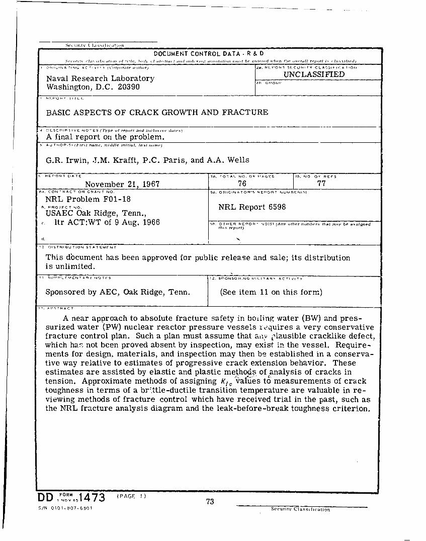
Se it' ri t \' II Id c, it I t•' ?
DOCUMENT CONTROL DATA- R & Dinr ",h I.,•,i .Illi i I ,J) 1 1 ,2, ,t•, tf h ,t, , , int , I In. I ',. .II , r•, r , fin mu .I It I nr "Id Iuli " ( , , -d I'tm t I rIf I r ,i, 1 1 ' f Ilssiheu
I 0I ., AINI A CrG A C TIV I (' ITT,...,r',...r) i!. RILP'OR7T Sf CURT TY CLA!SII CA A IOr.
Naval Research Laboratory UNCLASSIFIED
Washington, D.C. 20390"R'i-OPT TI TL t
BASIC ASPECTS OF CRACK GROWTH AND FRACTURE
4 t)[:SCPIPI IVE NOTES (Ty'pe oif report a•ri itcl,•,, darft
A final report on the problem.S AU THOMPS) (First name, middle initial, last riame,)
G.R. Irwin, .LM. Krafft, P.C. Paris, and A.A. Wells
C HEPOR T 11ATE 78. TOTA'_ NO. OF PAGES EFS. NO OF RERS
November 21. 1967 76 777,. CONTRACT OR GqANT NO 90. ORIGINATOR*S REP •RT NUV.INERISI
NRL Problem F01-18h. PRo,•¢T NO. NRL Report 6598USAEC Oak Ridge, Tenn.,
ltr ACT:WT of 9 Aug. 1966 91. OTHERI FPOr.T NOIS) (Any •rher ..iimherr. flint may be assignedthis repoVrt)
d. •
01S TTRIBUTION STATEMENT
This dbcument has been approved for public release and sale; its distributionis unlimited.
11 SUPPLFýE:N fARY NOTES 1•2. SBPONSORING MAILITARI ACTIVITY
Sponsored by AEC, Oak Ridge, Tenn. J (See item 11 on this form.)
I A US T RA CT
A near approach to absolute fracture safety in boiling water (BW) and pres-surized water (PW) nuclear reactor pressure vessels requires a very conservativefracture control plan. Such a plan must assume that ai-'v Olausible cracklike defect,which ha!ý not been proved absent by inspection, may exist in the vessel. Require-ments for design, materials, and inspection may then be established in a conserva-tive way relative to estimates of progressive crack extension behavior. Theseestimates are assisted by elastic and plastic methods of analysis of cracks intension. Approximate methods of assigning K Ivalues to measurements of cracktoughness in terms of a br'.ttle-ductile transition temperature are valuable in re-viewing methods of fracture control which have received trial in the past, such asthe NRL fracture analysis diagram and the leak-before-break toughness criterion.
D FORM 1 (PAGE 1)S , NOV 1 it.,817S 73S/N 0101-.807-6801 Security Classification
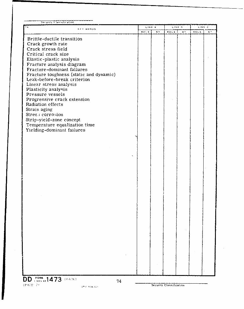
LINK A LINK¢ D LINK C
ROLE WIf ROLE F7 ROLE
Brittle-ductile transitionCrack growth rateCrack stress fieldCritical crack sizeElastic-plastic analysisFracture analysis diagramFracture-dominant failuresFracture toughness (static and dynamic)Leak-before-break criterionLinear stress analysisPlasticity analysisPressure vesselsProgressive crack extensionRadiation effectsStrain agingStres.i corro!;ionStrip-yield-zone conceptTemperature equalization timeYielding-dominant failures
DD 74 1tY1473(P Ac',! , I Security Classification