
BASI Report B/915/1020 - iasa.com.au
25
Puma SA 330J Helicopter VH-WOF Mermaid Sound WA 12 May 1991 BASI Report B/915/1020
Transcript of BASI Report B/915/1020 - iasa.com.au
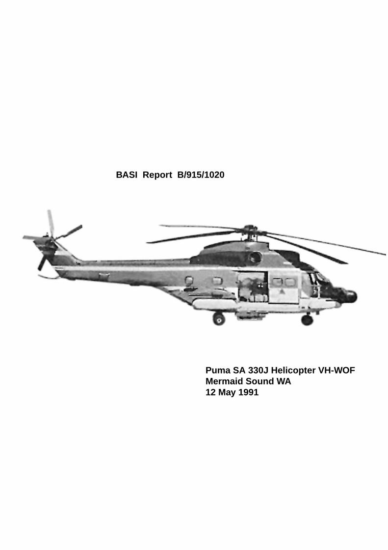
Puma SA 330J Helicopter VH-WOFMermaid Sound WA12 May 1991
BASI Report B/915/1020
Department of Transport and Communications
Bureau of Air Safety Investigation
ACCIDENT INVESTIGATION REPORTB/915/1020
Puma SA 330J Helicopter VH-WOF
Mermaid Sound Western Australia
12 May 1991
Released by the Director of the Bureau of Air Safety Investigation under theprovisions of Air Navigation Regulation 283
ii
This report was produced by the Bureau of Air Safety Investigation (BASI), PO Box 967, Civic Square ACT 2608.
The Director of the Bureau authorised the investigation and the publication of this report pursuant to his delegatedpowers conferred by Air Navigation Regulations 278 and 283 respectively. Readers are advised that the Bureau investi-gates for the sole purpose of enhancing aviation safety. Consequently, Bureau reports are confined to matters of safetysignificance and may be misleading if used for any other purpose.
As BASI believes that safety information is of greatest value if it is passed on for the use of others, copyright restrictions do not apply to material printed in this report. Readers are encouraged to copy or reprint for further dis-tribution, but should acknowledge BASI as the source.
ISBN 0 642 19382 7 June 1993
When the Bureau makes recommendations as a result ofits investigations or research, safety, (in accordance withits charter), is its primary consideration. However, theBureau fully recognises that the implementation ofrecommendations arising from its investigations will insome cases incur a cost to the industry.
Readers should note that the information in BASI reportsis provided to promote aviation safety: in no case is itintended to imply blame or liability.
iii
CONTENTS
SYNOPSIS ... . . . . . . . . . . . . . . . . . . . . . . . . . . . . . . . . . . . . . . . . . . . . . . . . . . . . . . . . . . . . . . . . . . . . . . . . . . . . . . . . . . . . . . . . . . . . . . . . . . . . . . . . . . . . . . . . . . . . . . . . . . . . . . . . . . . . . . . . . . . . . . . . . . . . . . . . . . . . . . . . . . . . . . . . . . . . . . . . . . . . . . . . . . . . . . . . . . . . . . . . . . . . . . . . . . . . . . . . . . . . . . . . . . . . . . . . . . . . . . . . . . . . . . . . 1
1. FACTUAL INFORMATION .... . . . . . . . . . . . . . . . . . . . . . . . . . . . . . . . . . . . . . . . . . . . . . . . . . . . . . . . . . . . . . . . . . . . . . . . . . . . . . . . . . . . . . . . . . . . . . . . . . . . . . . . . . . . . . . . . . . . . . . . . . . . . . . . . . . . . . . . . . . . . . . . . . . . . . . . . . . . . . . . . . . . . . . . . . . . . 1
1.1 History of the flight ... . . . . . . . . . . . . . . . . . . . . . . . . . . . . . . . . . . . . . . . . . . . . . . . . . . . . . . . . . . . . . . . . . . . . . . . . . . . . . . . . . . . . . . . . . . . . . . . . . . . . . . . . . . . . . . . . . . . . . . . . . . . . . . . . . . . . . . . . . . . . . . . . . . . . . . . . . . . . . . . . . . . . . . . . . . . . . . 1
1.2 Injuries to persons ... . . . . . . . . . . . . . . . . . . . . . . . . . . . . . . . . . . . . . . . . . . . . . . . . . . . . . . . . . . . . . . . . . . . . . . . . . . . . . . . . . . . . . . . . . . . . . . . . . . . . . . . . . . . . . . . . . . . . . . . . . . . . . . . . . . . . . . . . . . . . . . . . . . . . . . . . . . . . . . . . . . . . . . . . . . . . . . . . . . . 2
1.3 Damage to aircraft ... . . . . . . . . . . . . . . . . . . . . . . . . . . . . . . . . . . . . . . . . . . . . . . . . . . . . . . . . . . . . . . . . . . . . . . . . . . . . . . . . . . . . . . . . . . . . . . . . . . . . . . . . . . . . . . . . . . . . . . . . . . . . . . . . . . . . . . . . . . . . . . . . . . . . . . . . . . . . . . . . . . . . . . . . . . . . . . . . . . 2
1.4 Other damage ... . . . . . . . . . . . . . . . . . . . . . . . . . . . . . . . . . . . . . . . . . . . . . . . . . . . . . . . . . . . . . . . . . . . . . . . . . . . . . . . . . . . . . . . . . . . . . . . . . . . . . . . . . . . . . . . . . . . . . . . . . . . . . . . . . . . . . . . . . . . . . . . . . . . . . . . . . . . . . . . . . . . . . . . . . . . . . . . . . . . . . . . . . . . . . . . . . . . . . . 2
1.5 Personnel information ... . . . . . . . . . . . . . . . . . . . . . . . . . . . . . . . . . . . . . . . . . . . . . . . . . . . . . . . . . . . . . . . . . . . . . . . . . . . . . . . . . . . . . . . . . . . . . . . . . . . . . . . . . . . . . . . . . . . . . . . . . . . . . . . . . . . . . . . . . . . . . . . . . . . . . . . . . . . . . . . . . . . . . . . . . . . . 2
1.6 Aircraft information ... . . . . . . . . . . . . . . . . . . . . . . . . . . . . . . . . . . . . . . . . . . . . . . . . . . . . . . . . . . . . . . . . . . . . . . . . . . . . . . . . . . . . . . . . . . . . . . . . . . . . . . . . . . . . . . . . . . . . . . . . . . . . . . . . . . . . . . . . . . . . . . . . . . . . . . . . . . . . . . . . . . . . . . . . . . . . . . . . . . 3
1.7 Meteorological information ... . . . . . . . . . . . . . . . . . . . . . . . . . . . . . . . . . . . . . . . . . . . . . . . . . . . . . . . . . . . . . . . . . . . . . . . . . . . . . . . . . . . . . . . . . . . . . . . . . . . . . . . . . . . . . . . . . . . . . . . . . . . . . . . . . . . . . . . . . . . . . . . . . . . . . . . . . . . . 3
1.8 Aids to navigation ... . . . . . . . . . . . . . . . . . . . . . . . . . . . . . . . . . . . . . . . . . . . . . . . . . . . . . . . . . . . . . . . . . . . . . . . . . . . . . . . . . . . . . . . . . . . . . . . . . . . . . . . . . . . . . . . . . . . . . . . . . . . . . . . . . . . . . . . . . . . . . . . . . . . . . . . . . . . . . . . . . . . . . . . . . . . . . . . . . . . . . . . . . 3
1.9 Communications .. . . . . . . . . . . . . . . . . . . . . . . . . . . . . . . . . . . . . . . . . . . . . . . . . . . . . . . . . . . . . . . . . . . . . . . . . . . . . . . . . . . . . . . . . . . . . . . . . . . . . . . . . . . . . . . . . . . . . . . . . . . . . . . . . . . . . . . . . . . . . . . . . . . . . . . . . . . . . . . . . . . . . . . . . . . . . . . . . . . . . . . . . . . . . . 3
1.10 Aerodrome information ... . . . . . . . . . . . . . . . . . . . . . . . . . . . . . . . . . . . . . . . . . . . . . . . . . . . . . . . . . . . . . . . . . . . . . . . . . . . . . . . . . . . . . . . . . . . . . . . . . . . . . . . . . . . . . . . . . . . . . . . . . . . . . . . . . . . . . . . . . . . . . . . . . . . . . . . . . . . . . . . . . . . . . . . 3
1.11 Flight recorder .. . . . . . . . . . . . . . . . . . . . . . . . . . . . . . . . . . . . . . . . . . . . . . . . . . . . . . . . . . . . . . . . . . . . . . . . . . . . . . . . . . . . . . . . . . . . . . . . . . . . . . . . . . . . . . . . . . . . . . . . . . . . . . . . . . . . . . . . . . . . . . . . . . . . . . . . . . . . . . . . . . . . . . . . . . . . . . . . . . . . . . . . . . . . . . . . . . . . . . 3
1.12 Impact information and wreckage examination ... . . . . . . . . . . . . . . . . . . . . . . . . . . . . . . . . . . . . . . . . . . . . . . . . . . . . . . . . . . . . . . . . . . . . . . . . . . . . . . . . . . . . . . . . . . . . . . 4
1.13 Medical and pathological information ... . . . . . . . . . . . . . . . . . . . . . . . . . . . . . . . . . . . . . . . . . . . . . . . . . . . . . . . . . . . . . . . . . . . . . . . . . . . . . . . . . . . . . . . . . . . . . . . . . . . . . . . . . . . . . . . . . . . . . . . . . . . 4
1.14 Fire .. . . . . . . . . . . . . . . . . . . . . . . . . . . . . . . . . . . . . . . . . . . . . . . . . . . . . . . . . . . . . . . . . . . . . . . . . . . . . . . . . . . . . . . . . . . . . . . . . . . . . . . . . . . . . . . . . . . . . . . . . . . . . . . . . . . . . . . . . . . . . . . . . . . . . . . . . . . . . . . . . . . . . . . . . . . . . . . . . . . . . . . . . . . . . . . . . . . . . . . . . . . . . . . . . . . . . . . . . . . . . . . . . . . . . . . . 4
1.15 Survival aspects .. . . . . . . . . . . . . . . . . . . . . . . . . . . . . . . . . . . . . . . . . . . . . . . . . . . . . . . . . . . . . . . . . . . . . . . . . . . . . . . . . . . . . . . . . . . . . . . . . . . . . . . . . . . . . . . . . . . . . . . . . . . . . . . . . . . . . . . . . . . . . . . . . . . . . . . . . . . . . . . . . . . . . . . . . . . . . . . . . . . . . . . . . . . . . . . . . . . 4
1.16 Tests and research ... . . . . . . . . . . . . . . . . . . . . . . . . . . . . . . . . . . . . . . . . . . . . . . . . . . . . . . . . . . . . . . . . . . . . . . . . . . . . . . . . . . . . . . . . . . . . . . . . . . . . . . . . . . . . . . . . . . . . . . . . . . . . . . . . . . . . . . . . . . . . . . . . . . . . . . . . . . . . . . . . . . . . . . . . . . . . . . . . . . . . . . . . . . 5
1.16.1 Visual illusions .. . . . . . . . . . . . . . . . . . . . . . . . . . . . . . . . . . . . . . . . . . . . . . . . . . . . . . . . . . . . . . . . . . . . . . . . . . . . . . . . . . . . . . . . . . . . . . . . . . . . . . . . . . . . . . . . . . . . . . . . . . . . . . . . . . . . . . . . . . . . . . . . . . . . . . . . . . . . . . . . . . . . . . . 5
1.16.2 Glide path indication ... . . . . . . . . . . . . . . . . . . . . . . . . . . . . . . . . . . . . . . . . . . . . . . . . . . . . . . . . . . . . . . . . . . . . . . . . . . . . . . . . . . . . . . . . . . . . . . . . . . . . . . . . . . . . . . . . . . . . . . . . . . . . . . . . . . . . . . . . . . . . . . . . . 5
1.16.3 Trans-cockpit authority gradient and cockpit resource management .. . 6
1.16.4 Vortex-ring phenomenon ... . . . . . . . . . . . . . . . . . . . . . . . . . . . . . . . . . . . . . . . . . . . . . . . . . . . . . . . . . . . . . . . . . . . . . . . . . . . . . . . . . . . . . . . . . . . . . . . . . . . . . . . . . . . . . . . . . . . . . . . . . . . . . . . . . . . . 6
1.16.5 Power required versus power available .. . . . . . . . . . . . . . . . . . . . . . . . . . . . . . . . . . . . . . . . . . . . . . . . . . . . . . . . . . . . . . . . . . . . . . . . . . . . . . . . . . . . . . . . . . . . . . . 7
1.17 Other information ... . . . . . . . . . . . . . . . . . . . . . . . . . . . . . . . . . . . . . . . . . . . . . . . . . . . . . . . . . . . . . . . . . . . . . . . . . . . . . . . . . . . . . . . . . . . . . . . . . . . . . . . . . . . . . . . . . . . . . . . . . . . . . . . . . . . . . . . . . . . . . . . . . . . . . . . . . . . . . . . . . . . . . . . . . . . . . . . . . . . . . . . . 7
1.17.1 Crew procedures .. . . . . . . . . . . . . . . . . . . . . . . . . . . . . . . . . . . . . . . . . . . . . . . . . . . . . . . . . . . . . . . . . . . . . . . . . . . . . . . . . . . . . . . . . . . . . . . . . . . . . . . . . . . . . . . . . . . . . . . . . . . . . . . . . . . . . . . . . . . . . . . . . . . . . . . . . . . . . . . . . 7
1.17.2 Standardised approach technique ... . . . . . . . . . . . . . . . . . . . . . . . . . . . . . . . . . . . . . . . . . . . . . . . . . . . . . . . . . . . . . . . . . . . . . . . . . . . . . . . . . . . . . . . . . . . . . . . . . . . . . . . . . . . . 8
1.17.3 Company standardisation procedures .. . . . . . . . . . . . . . . . . . . . . . . . . . . . . . . . . . . . . . . . . . . . . . . . . . . . . . . . . . . . . . . . . . . . . . . . . . . . . . . . . . . . . . . . . . . . . . . . . 9
1.17.4 Other pilots’ techniques .. . . . . . . . . . . . . . . . . . . . . . . . . . . . . . . . . . . . . . . . . . . . . . . . . . . . . . . . . . . . . . . . . . . . . . . . . . . . . . . . . . . . . . . . . . . . . . . . . . . . . . . . . . . . . . . . . . . . . . . . . . . . . . . . . . . . . . . . . . . 9
1.17.5 Other operators’ techniques .. . . . . . . . . . . . . . . . . . . . . . . . . . . . . . . . . . . . . . . . . . . . . . . . . . . . . . . . . . . . . . . . . . . . . . . . . . . . . . . . . . . . . . . . . . . . . . . . . . . . . . . . . . . . . . . . . . . . . . . . . . 10
1.17.6 Operations in night visual meteorological conditions .. . . . . . . . . . . . . . . . . . . . . . . . . . . . . . . . . . . . . . . . . . . . 10
1.17.7 Training in the recognition of visual illusions .. . . . . . . . . . . . . . . . . . . . . . . . . . . . . . . . . . . . . . . . . . . . . . . . . . . . . . . . . . . . . . . . . . . . 10
1.17.8 Seating position and sight picture .. . . . . . . . . . . . . . . . . . . . . . . . . . . . . . . . . . . . . . . . . . . . . . . . . . . . . . . . . . . . . . . . . . . . . . . . . . . . . . . . . . . . . . . . . . . . . . . . . . . . . . . . 10
1.17.9 Marine pilots’ evidence ... . . . . . . . . . . . . . . . . . . . . . . . . . . . . . . . . . . . . . . . . . . . . . . . . . . . . . . . . . . . . . . . . . . . . . . . . . . . . . . . . . . . . . . . . . . . . . . . . . . . . . . . . . . . . . . . . . . . . . . . . . . . . . . . . . . . . . . . 10
1.17.10 Environmental changes .. . . . . . . . . . . . . . . . . . . . . . . . . . . . . . . . . . . . . . . . . . . . . . . . . . . . . . . . . . . . . . . . . . . . . . . . . . . . . . . . . . . . . . . . . . . . . . . . . . . . . . . . . . . . . . . . . . . . . . . . . . . . . . . . . . . . . . . . . 11
1.17.11 Other inadvertent and deliberate vortex-ring
entries in Puma aircraft .. . . . . . . . . . . . . . . . . . . . . . . . . . . . . . . . . . . . . . . . . . . . . . . . . . . . . . . . . . . . . . . . . . . . . . . . . . . . . . . . . . . . . . . . . . . . . . . . . . . . . . . . . . . . . . . . . . . . . . . . . . . . . . . . . . . . . . . . 11
1.17.12 Descent timing ... . . . . . . . . . . . . . . . . . . . . . . . . . . . . . . . . . . . . . . . . . . . . . . . . . . . . . . . . . . . . . . . . . . . . . . . . . . . . . . . . . . . . . . . . . . . . . . . . . . . . . . . . . . . . . . . . . . . . . . . . . . . . . . . . . . . . . . . . . . . . . . . . . . . . . . . . . . . . . . . . 11
1.17.13 Windscreen reflections .. . . . . . . . . . . . . . . . . . . . . . . . . . . . . . . . . . . . . . . . . . . . . . . . . . . . . . . . . . . . . . . . . . . . . . . . . . . . . . . . . . . . . . . . . . . . . . . . . . . . . . . . . . . . . . . . . . . . . . . . . . . . . . . . . . . . . . . . . . . 11
2. ANALYSIS ... . . . . . . . . . . . . . . . . . . . . . . . . . . . . . . . . . . . . . . . . . . . . . . . . . . . . . . . . . . . . . . . . . . . . . . . . . . . . . . . . . . . . . . . . . . . . . . . . . . . . . . . . . . . . . . . . . . . . . . . . . . . . . . . . . . . . . . . . . . . . . . . . . . . . . . . . . . . . . . . . . . . . . . . . . . . . . . . . . . . . . . . . . . . . . . . . . . . . . . . . . . . . . . . . . . . . . . . . . . . . . . . . . . . . . . 12
2.1 Pilot qualifications and experience ... . . . . . . . . . . . . . . . . . . . . . . . . . . . . . . . . . . . . . . . . . . . . . . . . . . . . . . . . . . . . . . . . . . . . . . . . . . . . . . . . . . . . . . . . . . . . . . . . . . . . . . . . . . . . . . . . . . . . . . . . . . . . . . . . . . . . 12
iv
2.2 Pilot medical factors .. . . . . . . . . . . . . . . . . . . . . . . . . . . . . . . . . . . . . . . . . . . . . . . . . . . . . . . . . . . . . . . . . . . . . . . . . . . . . . . . . . . . . . . . . . . . . . . . . . . . . . . . . . . . . . . . . . . . . . . . . . . . . . . . . . . . . . . . . . . . . . . . . . . . . . . . . . . . . . . . . . . . . . . . . . . . . . . . . . . . . 12
2.3 Aircraft serviceability .. . . . . . . . . . . . . . . . . . . . . . . . . . . . . . . . . . . . . . . . . . . . . . . . . . . . . . . . . . . . . . . . . . . . . . . . . . . . . . . . . . . . . . . . . . . . . . . . . . . . . . . . . . . . . . . . . . . . . . . . . . . . . . . . . . . . . . . . . . . . . . . . . . . . . . . . . . . . . . . . . . . . . . . . . . . . . . . . . . 12
2.4 Atmospheric conditions .. . . . . . . . . . . . . . . . . . . . . . . . . . . . . . . . . . . . . . . . . . . . . . . . . . . . . . . . . . . . . . . . . . . . . . . . . . . . . . . . . . . . . . . . . . . . . . . . . . . . . . . . . . . . . . . . . . . . . . . . . . . . . . . . . . . . . . . . . . . . . . . . . . . . . . . . . . . . . . . . . . . . . . . . . . 12
2.5 Conduct of the flight .. . . . . . . . . . . . . . . . . . . . . . . . . . . . . . . . . . . . . . . . . . . . . . . . . . . . . . . . . . . . . . . . . . . . . . . . . . . . . . . . . . . . . . . . . . . . . . . . . . . . . . . . . . . . . . . . . . . . . . . . . . . . . . . . . . . . . . . . . . . . . . . . . . . . . . . . . . . . . . . . . . . . . . . . . . . . . . . . . . . 12
2.5.1 Pilot’s perception of the type of flight .. . . . . . . . . . . . . . . . . . . . . . . . . . . . . . . . . . . . . . . . . . . . . . . . . . . . . . . . . . . . . . . . . . . . . . . . . . . . . . . . . . . . . . . . . . . . . . . . . 12
2.5.2 Initial stage of the approach ... . . . . . . . . . . . . . . . . . . . . . . . . . . . . . . . . . . . . . . . . . . . . . . . . . . . . . . . . . . . . . . . . . . . . . . . . . . . . . . . . . . . . . . . . . . . . . . . . . . . . . . . . . . . . . . . . . . . . . . . . . . . . 12
2.5.3 Management of cockpit resources .. . . . . . . . . . . . . . . . . . . . . . . . . . . . . . . . . . . . . . . . . . . . . . . . . . . . . . . . . . . . . . . . . . . . . . . . . . . . . . . . . . . . . . . . . . . . . . . . . . . . . . . . . . . . . 13
2.5.4 Rate of descent .. . . . . . . . . . . . . . . . . . . . . . . . . . . . . . . . . . . . . . . . . . . . . . . . . . . . . . . . . . . . . . . . . . . . . . . . . . . . . . . . . . . . . . . . . . . . . . . . . . . . . . . . . . . . . . . . . . . . . . . . . . . . . . . . . . . . . . . . . . . . . . . . . . . . . . . . . . . . . . . . . . . . . . . 13
2.5.5 Trans-cockpit authority gradient .. . . . . . . . . . . . . . . . . . . . . . . . . . . . . . . . . . . . . . . . . . . . . . . . . . . . . . . . . . . . . . . . . . . . . . . . . . . . . . . . . . . . . . . . . . . . . . . . . . . . . . . . . . . . . . . . 13
2.5.6 Intermediate stage of the approach ... . . . . . . . . . . . . . . . . . . . . . . . . . . . . . . . . . . . . . . . . . . . . . . . . . . . . . . . . . . . . . . . . . . . . . . . . . . . . . . . . . . . . . . . . . . . . . . . . . . . . . . . 13
2.5.7 Final stage of the approach and partial recovery ... . . . . . . . . . . . . . . . . . . . . . . . . . . . . . . . . . . . . . . . . . . . . . . . . . . . . . . . . . . . . . . . 13
2.6 Possible factors which can lead to premature touchdown
during a night approach to a helideck ... . . . . . . . . . . . . . . . . . . . . . . . . . . . . . . . . . . . . . . . . . . . . . . . . . . . . . . . . . . . . . . . . . . . . . . . . . . . . . . . . . . . . . . . . . . . . . . . . . . . . . . . . . . . . . . . . . . . . . . . . . . . . . 14
2.6.1 Possible scenarios .. . . . . . . . . . . . . . . . . . . . . . . . . . . . . . . . . . . . . . . . . . . . . . . . . . . . . . . . . . . . . . . . . . . . . . . . . . . . . . . . . . . . . . . . . . . . . . . . . . . . . . . . . . . . . . . . . . . . . . . . . . . . . . . . . . . . . . . . . . . . . . . . . . . . . . . . . . . . . . . 14
2.6.2 Low power and autorotation ... . . . . . . . . . . . . . . . . . . . . . . . . . . . . . . . . . . . . . . . . . . . . . . . . . . . . . . . . . . . . . . . . . . . . . . . . . . . . . . . . . . . . . . . . . . . . . . . . . . . . . . . . . . . . . . . . . . . . . . . . . . 14
2.6.3 Misjudged glide path and visual illusions during an approach ... . . . . . . . . . . . . . . . . . . . 14
2.6.4 ‘Vortex-ring state’ and visual illusions .. . . . . . . . . . . . . . . . . . . . . . . . . . . . . . . . . . . . . . . . . . . . . . . . . . . . . . . . . . . . . . . . . . . . . . . . . . . . . . . . . . . . . . . . . . . . . . . . 14
2.6.4.1 ‘Vortex-ring state’ .. . . . . . . . . . . . . . . . . . . . . . . . . . . . . . . . . . . . . . . . . . . . . . . . . . . . . . . . . . . . . . . . . . . . . . . . . . . . . . . . . . . . . . . . . . . . . . . . . . . . . . . . . . . . . . . . . . . . . . . . . . . . . . . . . . . . . . . . . . . . . . . . . . . . . . . . . . . . . . 14
2.6.4.2 Night visual meteorological conditions and visual illusions .. . . . . . . . . . . . . . . . . . . . . . . . . . . . . . 15
3. CONCLUSIONS ... . . . . . . . . . . . . . . . . . . . . . . . . . . . . . . . . . . . . . . . . . . . . . . . . . . . . . . . . . . . . . . . . . . . . . . . . . . . . . . . . . . . . . . . . . . . . . . . . . . . . . . . . . . . . . . . . . . . . . . . . . . . . . . . . . . . . . . . . . . . . . . . . . . . . . . . . . . . . . . . . . . . . . . . . . . . . . . . . . . . . . . . . . . . . . . . . . . . . . . . . . . . . . . . . . . . 17
3.1 Findings ... . . . . . . . . . . . . . . . . . . . . . . . . . . . . . . . . . . . . . . . . . . . . . . . . . . . . . . . . . . . . . . . . . . . . . . . . . . . . . . . . . . . . . . . . . . . . . . . . . . . . . . . . . . . . . . . . . . . . . . . . . . . . . . . . . . . . . . . . . . . . . . . . . . . . . . . . . . . . . . . . . . . . . . . . . . . . . . . . . . . . . . . . . . . . . . . . . . . . . . . . . . . . . . . . . . . . . . 17
3.2 Significant factors .. . . . . . . . . . . . . . . . . . . . . . . . . . . . . . . . . . . . . . . . . . . . . . . . . . . . . . . . . . . . . . . . . . . . . . . . . . . . . . . . . . . . . . . . . . . . . . . . . . . . . . . . . . . . . . . . . . . . . . . . . . . . . . . . . . . . . . . . . . . . . . . . . . . . . . . . . . . . . . . . . . . . . . . . . . . . . . . . . . . . . . . . . . 19
4 SAFETY RECOMMENDATIONS ... . . . . . . . . . . . . . . . . . . . . . . . . . . . . . . . . . . . . . . . . . . . . . . . . . . . . . . . . . . . . . . . . . . . . . . . . . . . . . . . . . . . . . . . . . . . . . . . . . . . . . . . . . . . . . . . . . . . . . . . . . . . . . . . . . . . . . . . . . . . . . . . . . . . . . . . . . . . . . 20
1
SYNOPSIS
The aircraft was tasked to carry out a marine pilot pick-up from a departingtanker. The flight was conducted by two pilots operating under night visual flightrules. Conditions were a moonless night with no defined horizon, no outsidelighting other than from the ship, and a surface wind that was light and variable.The ship was steaming in a northerly direction at 12.5 kts.
The flight proceeded normally until the aircraft was established on final approachto the helideck. As the aircraft descended through 500 ft the rate of descent hadincreased to about 1,000 ft/min. Although the pilot in command increased mainrotor pitch, the aircraft’s rate of descent continued to increase until just prior toimpact with the water. Both occupants were rescued approximately 1 h after theyevacuated the helicopter.
The report concludes that the standard approach technique used by the pilots,coupled with the prevailing weather conditions, caused the aircraft to enter a highrate of descent shortly after the aircraft started its normal final approach to thedeck. The high rate of descent was probably the result of entry to the incipientstage of ‘vortex-ring state’. A lack of visual cues and inadequate management ofcockpit resources prevented the crew from recognising the abnormal situationuntil the aircraft was well into the descent. Recovery action was commenced toolate to prevent impact with the water.
1. FACTUAL INFORMATION
1.1 History of the flight
The helicopter, with two pilots on board, was engaged in a night charter flight from Karrathato a departing liquefied natural gas (LNG) tanker to collect two marine pilots. The departureand night visual flight to the final descent point were normal.
Following an approach briefing from the pilot in command, and radio advice from the shipwhich indicated the relative wind was from 010° at approximately 5 kts, the crew commencedthe final approach from a ‘gate’, which is an initial approach point in level flight at 55 kts and550 ft AMSL, approximately 0.75 NM astern of the ship. At the time, the ship was steaming inMermaid Sound in a northerly direction at 12.5 kts, 20 km north-west of Dampier, WesternAustralia. As the aircraft passed through the ‘gate’, airspeed was reduced to below 35 kts(minimum indicator reading) and the descent was started by reducing main rotor pitch angleand selecting the correct sight picture in the windscreen. At approximately 500 ft the co-pilot,who was monitoring the instrument indications, reported the rate of descent as 1,000 ft/min.The allowable maximum rate of descent was 500 ft/min. The pilot increased the collectivepitch in an attempt to reduce the rate of descent. The corrective action had little or no effect asthe rate of descent continued to increase until a slight reduction occurred just prior to impact.
2
The accident occurred at 2133 hours Western Standard Time (Co-ordinated Universal Time +8 h) at position 20°24' south and 116°43' east, when the aircraft impacted the water, rolled tothe right and overturned. One of two liferafts stowed in the cabin area was dislodged andinflated. The flotation gear was not deployed.
The inflated liferaft provided sufficient additional buoyancy for the aircraft to remain afloatfor 2 h. The crew evacuated the aircraft through the co-pilot’s door and remained on thefloating wreckage before transferring to a dinghy dropped by another helicopter. They wererescued by boat approximately 70 min after the accident. The aircraft sank but wassubsequently recovered and transported to Karratha for inspection.
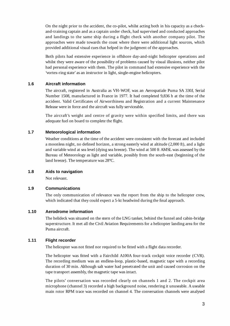
1.2 Injuries to persons
Injuries Crew Passengers Others
Fatal – – –
Serious 1 – –
Minor 1 – –
Total 2 – –
1.3 Damage to aircraft
The helicopter sustained substantial damage: the main rotor blades were destroyed, the tailboom and rotor were torn off, and the main fuselage was severely dented. In addition, the co-pilot’s seat collapsed and one flotation bag was torn from its stowage. The aircraft alsosuffered considerable damage as a result of salt-water immersion.
1.4 Other damage
Nil
1.5 Personnel information
The pilot in command was aged 53 years. He held a current Senior Commercial Pilot Licence(Helicopters) with a valid medical certificate and was endorsed to fly Puma SA 330Jhelicopters. At the time of the accident he had a total flying experience of 11,100 h, 1,400 of which were on the Puma helicopter. His most recent night-flying check had occurred on 12 December 1990. The pilot in command had been a check-and-training captain on thePuma aircraft during previous employment with the operating company and had extensiveexperience as a helicopter instructor.
The co-pilot was aged 42 years. He held a current Senior Commercial Pilot Licence(Helicopters) with a valid medical certificate and was endorsed to fly Puma SA 330Jhelicopters. At the time of the accident he had a total flying experience of 7,800 h, 2,400 ofwhich were on the Puma helicopter. His most recent night-flying check had occurred on 11 May 1991. In addition, he held an appointment as a company check-and-training captain.
Both pilots were adequately rested prior to the flight, were within their normal duty periodand had no known medical abnormalities at the time of the accident.
The pilot in command had been a crew member during at least eight other approaches to anLNG tanker during the preceding five months. Most of the approaches were made during theperiod around sunrise.
3
On the night prior to the accident, the co-pilot, whilst acting both in his capacity as a check-and-training captain and as a captain under check, had supervised and conducted approachesand landings to the same ship during a flight check with another company pilot. Theapproaches were made towards the coast where there were additional light sources, whichprovided additional visual cues that helped in the judgment of the approaches.
Both pilots had extensive experience in offshore day-and-night helicopter operations andwhilst they were aware of the possibility of problems caused by visual illusions, neither pilothad personal experience with them. The pilot in command had extensive experience with the‘vortex-ring state’ as an instructor in light, single-engine helicopters.
1.6 Aircraft information
The aircraft, registered in Australia as VH-WOF, was an Aerospatiale Puma SA 330J, SerialNumber 1508, manufactured in France in 1977. It had completed 9,836 h at the time of theaccident. Valid Certificates of Airworthiness and Registration and a current MaintenanceRelease were in force and the aircraft was fully serviceable.
The aircraft’s weight and centre of gravity were within specified limits, and there wasadequate fuel on board to complete the flight.
1.7 Meteorological information
Weather conditions at the time of the accident were consistent with the forecast and includeda moonless night, no defined horizon, a strong easterly wind at altitude (2,000 ft), and a lightand variable wind at sea level (dying sea breeze). The wind at 500 ft AMSL was assessed by theBureau of Meteorology as light and variable, possibly from the south-east (beginning of theland breeze). The temperature was 28°C.
1.8 Aids to navigation
Not relevant.
1.9 Communications
The only communication of relevance was the report from the ship to the helicopter crew,which indicated that they could expect a 5-kt headwind during the final approach.
1.10 Aerodrome information
The helideck was situated on the stern of the LNG tanker, behind the funnel and cabin-bridgesuperstructure. It met all the Civil Aviation Requirements for a helicopter landing area for thePuma aircraft.
1.11 Flight recorder
The helicopter was not fitted nor required to be fitted with a flight data recorder.
The helicopter was fitted with a Fairchild A100A four-track cockpit voice recorder (CVR).The recording medium was an endless-loop, plastic-based, magnetic tape with a recordingduration of 30 min. Although salt water had penetrated the unit and caused corrosion on thetape transport assembly, the magnetic tape was intact.
The pilots’ conversation was recorded clearly on channels 1 and 2. The cockpit areamicrophone (channel 3) recorded a high background noise, rendering it unuseable. A useablemain rotor RPM trace was recorded on channel 4. The conversation channels were analysed
4
for content, timings and stress, and the main rotor RPM channel was analysed for RPM,timings, noise and frequency.
Information from the CVR was used extensively during the analysis of the factors that led tothe accident. A review of the timings indicated that the co-pilot’s comment that the rate ofdescent was ‘a bit high’ started 17 s prior to impact, was completed 11 s prior to impact andwas acknowledged by the pilot in command between 10 s and 8 s prior to impact. The co-pilot made a comment about the radar altimeter reading 2 s prior to impact.
1.12 Impact information and wreckage examination
The helicopter contacted the water at a high rate of descent and at zero forward speed. It wasestimated that the rate of descent at impact was 2,000 ft/min. The flotation bags were not setto inflate automatically and they were not inflated manually. First contact with the water wasmade by the lower fuselage section that slopes up at 15° aft of the cabin floor area. The mainrotor blades shattered when they struck the water and aft fuselage. The tail boom was severedin a downwards direction by the impact. The tail rotor blades were severely damaged.Immediately after the initial impact, the aircraft rolled to the right and the forward rightfuselage made solid contact with the water. During this contact, the lower right windscreenpanel was destroyed and the surrounding fuselage severely dented. The force of the impactcaused the co-pilot’s seat to collapse and one of the liferafts stowed in the cabin area wasdislodged, causing it to inflate.
The recovered wreckage was examined in detail at Karratha. A number of instruments andthe CVR were removed for examination. It was determined that all damage was a result ofwater impact and immersion and that all systems appeared capable of normal operation priorto the impact.
1.13 Medical and pathological information
A review of the pilots’ medical histories indicated that neither pilot had any known pre-existing medical or psychological condition that might have contributed to the accident.There was no evidence of pilot incapacitation during the accident sequence.
The pilot in command received head injuries during the impact that caused somedisorientation and led to his delay in exiting the aircraft. He also ingested a considerableamount of water. The accident injuries caused significant post-trauma medical problems forthe pilot in command.
1.14 Fire
There was no fire.
1.15 Survival aspects
The crew were not expecting to make contact with the water and were unprepared when theaircraft did so. In addition, the pilot in command was dazed when he was thrown against theside of the cockpit during the impact. Both pilots were disorientated by the inverted positionof the helicopter and the darkness. However, they reported that they were able to find theirway out through the co-pilot’s door because it was highlighted by the emergency striplighting. The operator had fitted this emergency exit lighting to the cockpit doors following aprevious accident.
The aircraft was fitted with flotation equipment. The emergency flotation system was armedand the co-pilot was monitoring the manual inflation system, as briefed, during the descent.
However, the unexpected impact prevented its activation. The aircraft was fitted withimmersion switches which would cause the flotation gear to inflate if the aircraft wasimmersed in water, but these were not armed. The company was awaiting approval from theCivil Aviation Authority (CAA) before activating the system. The right-hand flotation bagwas dislodged by the impact.
The impact dislodged one of two liferafts stowed in the cabin area. It inflated inside the cabin,providing sufficient additional buoyancy to keep the fuselage afloat for about 2 h. The crewremained on the wreckage while they awaited rescue.
A liferaft was dropped to the crew from another helicopter approximately 1 h after theaccident. The crew encountered difficulty operating the inflation mechanism as they had toswim to the raft and each time they pulled on the toggle the raft followed. The raft waseventually inflated by one of the crew placing his feet on the raft as he pulled the toggle.
The tanker was unable to provide assistance as it required a considerable distance to slow andturn about. The crew was rescued by a boat from a tender vessel approximately 70 min afterthe accident.
The aircraft was fitted with an automatically deployable emergency locator transmitter(ADELT). Although the ADELT was armed it did not deploy because the impact sequenceprevented the immersion switch entering the water before electrical power from the mainbattery was terminated by submersion.
1.16 Tests and research
1.16.1 Visual illusions
Many previous helicopter accidents during night approaches to landing areas over darkterrain or water have been attributed to the lack of sufficient visual information to enable thepilot to judge his position in space accurately.
UK Department of Transport Air Accidents Investigation Branch Report 5/88 concerning anaccident involving a night approach to a helideck states that:
...a difficulty which is relevant to approaches to platforms and ships at night, is that thesemay be the only light source in an otherwise totally dark environment. A single light sourcephenomenon has long been recognised by the aviation community as one which contributesnothing to the pilot’s judgement of distance. In this context, although the platforms or shipshave considerably more than one light, when viewed from a distance [e.g. at thecommencement of a final approach], they may be considered as a single light source. Theusual effects of this phenomenon are that the pilot is deprived of the visual cues normallyassociated with daylight vision. These are:
1. the relationship of the object to the horizon;2. the relationship to other objects and the surface texture between the aircraft and the
object in view; and3. the use, for ranging, of the angle subtended at the viewer’s eye by the object, because:
(a) the absolute size of the object is uncertain, and(b) the judgement of this angle when it is very small is difficult.
1.16.2 Glide path indication
Investigations of this and other accidents that have occurred during approaches to offshorelanding areas (particularly at night) and comments made by both pilots and human factorspecialists during this investigation about the difficulty in judging the approach path, indicatethat the use of a glide path indicator located at the landing area is essential. A
5
recommendation to this effect was made in the UK Air Accidents Investigation Branch’sReport 5/88.
1.16.3 Trans-cockpit authority gradient and cockpit resource management
Studies of accidents involving crew members with comparable experience levels (especiallyhigh levels) indicate that crew interaction and supervision tend to diminish once individualmembers assume that other crew are fully capable of conducting safe operations and as aresult the type of detailed assistance and/or supervision that they might normally provide toless experienced crew members is not required.
The outcome is a flattening of the trans-cockpit authority gradient as the pilot in commandfails to establish full authority over the rest of the crew (approach brief, procedures, etc.) andthe effectiveness of cross checking between individual crew members is reduced.
In this accident, the co-pilot reported that after advising the pilot of the high rate of descentand observing that action had been taken to correct it, he did not feel there was anyrequirement to continue to monitor the rate of descent as the pilot in command was veryexperienced and knew what he was doing.
1.16.4 Vortex-ring phenomenon
In his paper ‘Helicopter wreckage analysis’, presented at the 1979 Forum of the InternationalSociety of Air Safety Investigators, Jerry T. Dennis of the US National Transportation SafetyBoard stated that:
Settling with power can best be described as settling in the aircraft’s own downwash.Technically it is called the ‘Vortex Ring State’, where the high rate of descent exceeds thenormal downwash velocity on the inner blade sections and they stall. This then causes asecondary vortex which results in turbulent flow over much of the rotor disk. It has beendemonstrated that the stall starts at the hub and migrates outwards towards the tip as therate of descent increases. Increased angle of attack (collective application) only increases thestalled area and resultant rate of descent. Descent rates exceeding 3,500 ft/min have beenrecorded. According to FAA [US Federal Aviation Administration] Advisory Circular 61-13B, the pilot may get into this condition by:
1. Attempting an Out of Ground Effect (OGE) hover above the hovering ceiling of thehelicopter;
2. Attempting to hover out of ground effect without maintaining precise altitude control;
3. A steep, powered approach in which the airspeed is permitted to drop nearly to zero.
Advisory Circular 61-13B further indicates that the following combination of conditions arelikely to cause settling with power:
1. A vertical or near vertical descent of at least 300 ft/min. Actual critical rate depends on thegross weight, RPM, density altitude and other pertinent factors;
2. The rotor system must be using some of the available engine power (20–100%);
3. The horizontal velocity must be no greater then 10 mph. That velocity is not necessarilythe velocity across the ground, but the transverse velocity through the rotor disc. As aresult a deceleration or approach can meet all the requirements, especially if downwind.
Recovery can be accomplished by increasing the forward speed and flying out or loweringthe collective to reduce the stalled area.
Anecdotal evidence indicates that it is widely believed within the aviation industry that‘vortex-ring state’ is always accompanied by pitching and/or yawing and rolling motions thatgive the pilot warning of possible loss of control. This information is usually correct if theaircraft enters a fully developed ‘vortex-ring state’; however, evidence was obtained fromflight tests and from four experienced Puma pilots that the Puma can begin entry to the
6
‘vortex-ring state’ with little or none of the expected sensory indications. A lack of indicationis more likely if the airflow around the tail rotor is clear of the downwash as would be the caseif there were a tailwind or the aircraft were moving backwards.
During the course of this investigation a series of vortex-ring demonstration flights in anaircraft identical to that involved in the accident were carried out. These flights showed that atthe incipient stage of entry to vortex ring, a Puma, at a weight similar to that of the accidentaircraft, displayed some mild random yawing (up to ±10°) and an increase in vibration. Thepitching and rolling symptoms did not become evident until about the same time as the rateof descent indication had increased markedly (to about 2,000–2,500 ft/min).
It was also found that increasing the rotor-pitch angle by about 1–2° at the incipient stage ofvortex-ring entry resulted in an increase in rate of descent from about 1,000 ft/min to2,000–2,500 ft/min in about 5–10 s, at which point the nose tended to pitch down andrandom rolling occurred. Recovery was accomplished very quickly by applying forward cyclicand smoothly increasing power (rotor-pitch angle) once airspeed had registered and wasincreasing. Height loss from initiation of recovery averaged 200–300 ft. (It should be notedthat entry altitudes for these demonstrations ranged from 8,000 ft down to 4,000 ft.)
1.16.5 Power required versus power available
The demonstration flights indicated that it was possible to enter a very high rate of descentcondition, similar to that encountered during this accident, if the pilot failed to increase powersufficiently to meet the demand for increased rotor thrust required as the aircraft was flownthrough the entry procedures at the ‘gate’. At conditions approximating the accident aircraft’sweight and density altitude, it was found that if the rotor-pitch angle was left at approximately8° (a typical power setting as the entry to the descent is established), with the airspeedindicating between 0 kts and 30 kts, the rate of descent was at or beyond 2,500 ft/min, thisbeing the maximum on the indicator scale. In this condition heavy vibration was present, butthe rate of descent reduced immediately power was increased. However, if the nose was held upsuch that airspeed further decreased, the helicopter entered ‘vortex-ring state’ accompanied byyawing, rolling and nose-down pitching with no discernible change in the rate of descentindication.
1.17 Other information
1.17.1 Crew procedures
The pilot in command indicated that he normally used a reducing airspeed technique whenmaking an approach to an offshore landing area. He was uncomfortable with the low-speedapproach technique in use at Karratha as he felt it placed the aircraft too close to theconditions required for vortex-ring entry. On this flight, as the co-pilot was a current check-and-training captain, the pilot in command reported that he used the low-speed approachtechnique in order to avoid any adverse criticism from the co-pilot. Although the flight wasprogrammed as a normal ferry flight, the pilot in command still felt that it was a check flight.
The co-pilot was considered by his peers to be a careful and accurate check-and-trainingcaptain who would be expected to comment on any deviations from the standard low-speedapproach technique. No deviations other than the high rate of descent and the radar altimeterreading of 100 ft were recorded on the CVR.
The company’s Operations Manual requires the non-handling pilot (in this case the co-pilot)to monitor the rate of descent and collective pitch and to inform the handling pilot if the rate
7
of descent exceeds 500 ft/min or if the pitch angle is less than 10°. The co-pilot did monitorthe instruments and called the rate of descent exceedance of 1,000 ft/min. The co-pilotindicated that, as a check-and-training captain, it was his habit to monitor the approach inmore detail than if he were just an ordinary co-pilot. Consequently he divided his attentionbetween monitoring the instruments and checking the sight picture.
The pilot in command reported that he had observed a reading of 480 ft on the altimeter ashe increased the collective-pitch setting from 10° to 11° following the co-pilot’s warning. Theco-pilot reported he observed 450+ ft and 10° of rotor-pitch angle at the time of his call.
Experience has shown that during an approach where there is a possibility of visual illusionsit is imperative that one pilot constantly monitor the instruments until the visual cuesbecome the primary source of guidance (late in the approach). Although there wereindications during the initial approach that the lack of visual cues might be a problem,neither pilot recognised this and no allowance was made during the planning and briefing forthe final approach.
1.17.2 Standardised approach technique
The manufacturer’s flight manual for the Puma SA 330J indicates that the minimumapproach speed to be used until the aircraft is 50 ft above pad height is 43 kts. The operatorbelieved that the danger of a tail strike during the flare required to reduce airspeed from 43 ktsto zero in 50 ft was too great. This danger, plus
(a) a Flight Manual requirement to maintain a high minimum engine RPM during thedescent,
(b) the desire always to have the option to continue with the landing or overshoot at anystage during the approach, and
(c) an attempt to introduce a standardised approach,led to the development of the standard approach procedure published in the operator’sOperations Manual. This procedure is used by the operator in all its Puma operationsworldwide.
The Normal Operating Procedures for the operator’s ‘steep’ approach stated the following(November 1989):
Where obstructions prevent a ‘straight in’ approach it may be necessary to make an approachinto wind to a point above and alongside the helideck, and then to move sideways anddownwards to land.
During the final approach to an offshore helideck, the handling pilot should establish theapproach path, with ground speed less than 50 kts, by 500 ft above the deck height. Duringthe approach the NHP [Non Handling Pilot] is to monitor the Rate of Descent andCollective Pitch and inform the HP [Handling Pilot] whenever the R.O.D. [Rate of Descent]exceeds 500 ft/min or Collective Pitch is less than 10°. The HP is to acknowledge this.
An approach decision point is to be established 150 ft above deck height. If at ADP orbeyond, the R.O.D exceeds 500 ft/min or Collective Pitch is less than 10°, the handling pilotis to overshoot.
The aircraft is ‘committed’ to land when the helideck, (or the obstructions adjacent to it),prevent an overshoot using maximum single-engine power. At the committal point the HP isto call ‘committed’.
The operator indicated that these procedures were developed during the introduction ofoffshore operations and reviewed and adjusted slightly following a Puma accident in the mid-1980s. The procedures do not set out in detail the piloting technique to be used, nor do they
8
indicate if there are any special requirements for night operations. Over the years the pilotingtechnique used at Karratha was refined around these procedures. The refined approach orlow-speed approach technique differed from the one used by the operator’s Puma pilots inother parts of the world in that, at Karratha, a low (below 32 kts) airspeed was used duringthe descent from the ‘gate’ to the committal point instead of a reducing airspeed (500 ft/50kts, 400 ft/40 kts, etc.). Discussion with the operator indicated that the main reason for thechange appeared to be an attempt to prevent the aircraft from entering an overshootcondition caused by the normally very light wind conditions encountered in the north-westof Western Australia. The change also made airspeed control less difficult as it removed onevariable from the approach. The low-speed approach technique used at Karratha requiredthat the pilot:
(a) Establish the aircraft in level flight at the ‘gate’ (500 ft + deck height, 50 kts +headwind speed with the sight picture in the correct position on the windscreen).
(b) Raise the nose to reduce airspeed, at the same time lowering the collective control toprevent altitude increasing.
(c) As the airspeed approaches the ‘burble’, (an aerodynamic vibration where actualairspeed is unknown but is less than 32 kts which is, in turn, below the minimumgauge indication of 35 kts), commence descent by lowering the nose and selecting thecorrect glide path visually.
(d) Adjust attitude and rotor-pitch angle to achieve the correct glide path, with theairspeed ‘in the burble’, with a rate of descent of 500 ft/min and rotor-pitch angle notless than 10°.
(e) At a radar altitude of 150 ft + the deck height (bug should be set), if all parameters aresatisfactory, call ‘committed’ and begin to reduce the rate of descent and forwardspeed to arrive over the Puma circle on the deck in a 15-ft wheel-height hover. If theparameters are not satisfactory the aircraft has to overshoot.
(f) Acknowledge and take corrective action when informed by the monitoring non-handling pilot that the rate of descent has exceeded 500 ft/min or that the collectivepitch angle is less than 10°.
Evidence indicates that the aerodynamic ‘burble’ starts when the airspeed falls below 32 ktsand does not vary noticeably with variations in airspeed below that figure. Although theneedle on the airspeed indicator moves as speed is adjusted, the various errors caused by therotor downwash, static and dynamic port positions make any reading unreliable as a speedindicator.
1.17.3 Company standardisation procedures
The operator maintains a comprehensive training and standardisation system involving localcheck-and-training captains and local and international standardisation checks. Although thelow-speed approach technique was different to the technique used in the company’soperations in other parts of the world, it complied with the broad procedures set out in theOperations Manual. The low-speed approach technique had been used by a number of pilots(at least 10) during both local and international standardisation checks without anycomment.
1.17.4 Other pilots’ techniques
Following the accident, at least two other company pilots indicated that they did not normallyuse the low-speed approach technique when flying without check-and-training supervision asthey considered the approach uncomfortable and possibly unsafe. Their concerns were basedon their overall helicopter experience rather than on any actual vortex-ring experience in the
9
Puma. The technique normally used by these pilots involved the use of a flatter approach witha reducing airspeed. Most if not all of the pilots contacted seemed unaware of the possiblelack of what are considered to be normal indications of entry to ‘vortex-ring state’.
1.17.5 Other operators’ techniques
Another Puma operator which had previously used the accident flight operator’s check-and-training system, discontinued the slow-speed approach because it considered the practiceunsafe. Two other offshore operators of Puma aircraft indicated that they did not use theslow-speed approach and conformed to the approach specified in the approved Aircraft FlightManual.
1.17.6 Operations in night visual meteorological conditions
The company’s Operations Manual contains specific instructions on the management ofcockpit resources during approaches in instrument meteorological conditions. The HP(usually the co-pilot) flies the aircraft on instruments until the NHP has visually acquired thelanding area. At that point the NHP takes over and lands the aircraft.
The conditions on night approaches can be as difficult as those in instrument conditions. Theoperator’s training system emphasised the importance of instrument monitoring duringnight operations in visual conditions and addressed the possibility of visual illusions. TheOperations Manual does not contain any specific instructions for night approaches in visualconditions, apart from the requirement to monitor rate of descent and collective pitch settingduring all offshore approaches.
1.17.7 Training in the recognition of visual illusions
Although night visual illusions in helicopter operations are recognised as a significantproblem, evidence indicates that whilst companies involved in night offshore helicopteroperations give general coverage to visual illusions during night flying training, they do notprovide specific training to their pilots in the recognition of cues to the possibility of visualillusions. The pilots in this accident advised that they had not received any specific training.
1.17.8 Seating position and sight picture
Because of its shape and height, the Puma instrument panel interferes with the sight pictureavailable to many pilots, who have to lean to one side to maintain visual contact with thedeck. It is possible under certain wind conditions for one pilot to lose sight of the deckcompletely. Other factors affecting the sight picture are pilot stature and seat height. Duringthe final approach the co-pilot was unable to see the helideck without making an exaggeratedmovement of his head.
1.17.9 Marine pilots’ evidence
The senior marine pilot on board the ship confirmed that the aircraft had appeared to bemaking a normal approach when, shortly after it commenced its final approach, the aircraftentered a very high rate of descent which was reduced just before impact. The impactoccurred about the same distance behind the ship as the aircraft was when the descentstarted. He likened the descent to a ‘shooting star’. This information was supported by asecond marine pilot also on board the ship. The marine pilot’s job requires that he be able tojudge distances from single light sources at night on the surface.
10
Calculations indicate that, if the approach commenced 0.5–0.75 NM behind the ship, theaircraft probably had a low, zero or negative ground speed during part of the approach. Thepilots reported that this was not evident to them.
1.17.10 Environmental changes
The possibility that a sudden loss of height may have been caused by rotors or turbulencegenerated by the ship’s superstructure, the gas efflux from the ship or low-level winds over theBurrup Peninsula was examined. Information provided by the company using the LNGcarriers, the ship’s manufacturer and the Bureau of Meteorology indicated that neither thesenor the possibility of debilitating gases being exhausted from the ship could have been factorsin the accident.
1.17.11 Other inadvertent and deliberate vortex-ring entries in Puma aircraft
One other case of inadvertent entry to an incipient ‘vortex-ring state’ in one of the operator’sPuma aircraft at Port Hedland was disclosed during the investigation. This case was notassociated with an approach to a helideck. However, the aircraft did enter a very high rate ofdescent very quickly and without exhibiting any noticeable yawing or rolling. The aircraftdescended from 1,000 ft to 200 ft above ground level before recovery was effected. Otherinadvertent entries to the ‘vortex-ring state’ were reported by other operators. These occurredmainly during long-line sling operations. No other cases of entry during offshore landingswere disclosed. Extensive discussions were held with four experienced Puma pilots andinformation relating to vortex-ring entries was obtained from the manufacturer’s test pilot.The consensus was that whilst it was difficult to deliberately fly the aircraft into a ‘vortex-ringstate’, particularly at a height where ground reference was not available, the aircraft couldinadvertently enter the ‘state’ whilst exhibiting few of the normal symptoms. Recovery wasimmediate when correct recovery action was taken. All except one of the reportedoccurrences were in aircraft not fitted with flotation equipment. The effect that thisequipment might have on the entry symptoms could not be determined. The flight testingdid indicate however, that the symptoms were not always significant, even in an aircraft fittedwith flotation gear.
1.17.12 Descent timing
Standard (reducing airspeed) and slow (low-speed approach technique) approaches wereflown by two of the operator’s check-and-training pilots during demonstration flights. At leastfour of these approaches were timed from initiation of the descent at the ‘gate’ to terminationat the hover over the target landing point. The approaches consistently took approximately 70 s. The CVR indicated that the accident approach lasted 27 s from the ‘gate’ position.
1.17.13 Windscreen reflections
The instrument panel in the Puma helicopter is designed so that it does not cast reflections onthe windscreen during night operations. During the initial stages of the approach the pilot incommand adjusted the cockpit lighting so that his view through the windscreen was notinhibited. Conditions at the time of the accident were dry with no visible moisture.
The pilots reported that, during the approach, their vision was not affected by either reflectionson the windscreen or by refraction through moisture on the outside of the windscreen.
11
2. ANALYSIS
2.1 Pilot qualifications and experience
Both pilots held appropriate licences and endorsements and were very experienced in generalhelicopter operations. The co-pilot, who was also a check-and-training captain, had recentexperience in night offshore landings. As a unit, the crew were suitably qualified for a normalnight operation to the ship. However, neither pilot’s general training in night visual illusionshad included formal instruction in the recognition of cues.
2.2 Pilot medical factors
Neither pilot had any known pre-existing condition that might have been a factor in theaccident.
2.3 Aircraft serviceability
The aircraft was fully serviceable and it was determined that all damage was a result of waterimpact and immersion. Equipment or system failures were not considered to be factors in theaccident.
2.4 Atmospheric conditionsAtmospheric and environmental conditions probably led to the crew encountering a visualillusion and prevented them from recognising the abnormal situation during the high rate ofdescent. The wind conditions, with the possible onset of a south-easterly land breeze as theaircraft descended through 500 ft, probably assisted the aircraft’s entry to a high rate ofdescent by creating conditions for a zero or negative airspeed.
2.5 Conduct of the flight
2.5.1 Pilot’s perception of the type of flight
Although the accident flight was not scheduled as a check-and-training flight, the pilot incommand indicated that he treated it as such and attempted to fly the approach to the shipexactly as required by the local company technique. This was at variance to his normaltechnique where he flew a reducing airspeed approach until he reached the committal point.He used this procedure because of his fears of entering a ‘vortex-ring state’ if he used therecommended technique.
2.5.2 Initial stage of the approach
The evidence indicates that the approach was completely normal until the aircraft had passedthrough the ‘gate’ during the final approach to the ship. As the aircraft settled into thedescent, approximately 17 s prior to impact, neither pilot was aware of any problem otherthan the higher than normal rate of descent. Under the prevailing conditions it is likely thatthis was the only reliable cue that the aircraft was possibly about to enter an uncontrolleddescent. The co-pilot drew the pilot’s attention to the excessive rate of descent, as required,and the pilot responded and took corrective action by increasing the collective pitch anglefrom 10° to 11°. However, neither pilot continued to monitor the rate of descent and bothappeared to have turned their attention to the visual sight picture. The co-pilot should havemonitored the rate of descent until he was satisfied that the corrective action had the desiredeffect. Both pilots expected the approach to be normal from that point and were not
12
anticipating any further formal checks until the approach decision point check of rate ofdescent and collective pitch, approximately 330 ft and 30–40 s later.
2.5.3 Management of cockpit resources
Available cockpit resources were not being managed effectively in the prevailingcircumstances. Tasks which could be described as visual or instrument monitoring wereinappropriately shared. Because the crew had not recognised that there might be problemswith visual illusions, the co-pilot was alternating his scan between the instruments andoutside the cockpit, rather than monitoring the instruments continuously. In the absence ofany recognition that there might be a problem, the pilot in command had not briefed anyalternative procedures. In general, although possible problems were covered during normalnight flying training, there appeared to be a lack of recognition that night visual approachesrequired a different technique than day visual approaches. The company’s Operations Manualdid not underscore this difference.
2.5.4 Rate of descent
An excessive rate of descent was required to descend from 480 ft to sea level in less than 11 s.The aircraft probably entered the high rate of descent condition at the time the co-pilot madehis report. The action taken by the pilot in command did not return the rate of descent tonormal and it continued to accelerate.
2.5.5 Trans-cockpit authority gradient
The very flat trans-cockpit authority gradient (see 1.16.3) resulted in a less than optimum useof the resources available in the cockpit. The co-pilot was aware of the pilot in command’sexperience and when he called the high rate of descent and observed that action had beentaken to correct the problem, he did not believe it was necessary to continue to monitor therate of descent to ensure that it was reduced below 500 ft/min.
2.5.6 Intermediate stage of the approach
It was the normal practice of the co-pilot to conduct a scan that included a check of the visualpicture and other instruments before coming back to the rotor-pitch angle and rate of descentindicator. The co-pilot’s seating position required that he look around the instrument panelto observe the sight picture; as a result, he had to look away from the instruments. The veryshort time interval from the completion of the pilot in command’s attempted correctiveactions to impact (8 s), and possibly the distraction caused by the radar altimeter alertinglight located on the instrument, prevented the co-pilot from completing his scan. By the timethe co-pilot noted the radar altimeter reading it was too late to prevent the accident.
2.5.7 Final stage of the approach and partial recovery
The marine pilots reported that the aircraft appeared to commence recovery just prior toimpact. The co-pilot made a comment over the intercom about the radar altimeter reading, 2 sprior to impact. It could not be determined what action the pilot took; however it is unlikelythat his actions had any significant effect in the time available. The ship had reported a 5-ktnortherly wind during the helicopter’s approach. The pilots reported that the surface windwas very light and variable after the accident. The meteorological assessment indicated thatthe 5-kt wind may have been the last of a dying sea breeze, which only had an effect close tosea level. As the helicopter descended into what was a headwind, it is possible that thisalleviated the cause of the uncontrolled descent and that the aircraft began recovery withoutpilot input.
13
2.6 Possible factors which can lead to premature touchdown during a nightapproach to a helideck
2.6.1 Possible scenarios
Research and flight testing indicates that a Puma helicopter can fly an incorrect flight path orachieve rates of descent in the order of those encountered on the accident flight in a numberof ways. The most likely of these are as follows:
(a) The pilot fails to re-introduce power after the initial power reduction at the ‘gate’,and the crew do not recognise that the rate of descent is excessive or that the flight pathis incorrect.
(b) The pilot lowers the collective and places the aircraft in autorotation, eitherdeliberately or inadvertently, and the other crew member fails to note that this hasoccurred.
(c) The crew encounter a visual illusion which causes them to misjudge the correctflight path and they allow the aircraft to fly into the ground/water.
(d) The crew do not level the aircraft at the gate but continue their descent from thepoint where they were lined up on their final approach and a visual illusion preventsthem from recognising the incorrect descent path.
(e) The aircraft begins an entry to a ‘vortex-ring state’ and the crew do not recognise it.
2.6.2 Low power and autorotation
Sufficient evidence is available to discount both low power and autorotation as factors. Bothpilots reported a minimum pitch angle of 10° during the accident flight and the pilot incommand reported that he had increased pitch angle from 10° to 11° following the co-pilot’s1,000 ft/min call. Analysis of the signature of rotor RPM recorded on the CVR confirmed thatthe pilot in command increased rotor-pitch angle following the co-pilot’s call and there is noevidence that the aircraft entered autorotation.
2.6.3 Misjudged glide path and visual illusions during an approach
A hypothesis that was considered was that the aircraft had entered a continuous descent fromthe time it was lined up on final approach at 700 ft. The CVR RPM trace indicated areduction in main rotor RPM probably as the aircraft was levelled at 550 ft prior to passingthrough the ‘gate’. The aircraft was observed to be making a normal approach before itcommenced a high rate of descent described as being like a ‘shooting star’. The rate of descentat impact was estimated to be in the vicinity of 2,000 ft/min and it was reported that therehad been a reduction just prior to impact. Extensive discussions with the crew and the ship’spilots, and further analysis of the CVR, indicated that a continuous descent from 700 ft, or acontrolled misjudged flight path (normal result of succumbing to the effects of visualillusions) was unlikely.
2.6.4 ‘Vortex-ring state’ and visual illusions
2.6.4.1 ‘Vortex-ring state’
The Operations Manual contains general instructions on how an approach to an offshorelanding area is to be conducted but it does not set out the piloting techniques to be used nordoes it indicate if there are any special requirements for night approaches. Although thecompany’s Puma operations in other parts of the world use a reducing airspeed approach fromthe ‘gate’ to the committal point, a different procedure involving the use of a constant very lowairspeed was in use at Karratha. The reducing airspeed approach minimised the risk of the
14
aircraft encountering all of the conditions required for ‘vortex-ring state’ during the approachas the aircraft does not enter the ‘burble’ until it is close to the landing area and the rate ofdescent has been reduced to less than 500 ft/min. At that point in the approach, the crew havethe added advantage of being close enough to the landing area to be able to visually assess theirflight path and closure rate. The low-speed approach technique, which complied with thebroad Operations Manual procedures, reduced the airspeed to the ‘burble’ very early in theapproach and made assessment of closing rate difficult. Whilst some pilots used the reducingairspeed approach during their day-to-day flying, most used the low-speed approachtechnique when undergoing a check ride with a local or international check pilot. No adversecomments were made about the use of the low-speed approach technique by the check pilotsand it is possible that the dangers of this approach, particularly at night, were not recognised.
The operator’s insistence on the use of the low-speed approach technique for its Karrathaoperations meant that their aircraft were always operating in a flight envelope where the riskof inadvertent entry to ‘vortex-ring state’ was greater than if they had used the reducingairspeed technique.
Most of the parameters required for an aircraft to enter the ‘vortex-ring state’ are presentduring an approach using the low-speed approach technique. To achieve the final parameterof low, zero or negative airspeed, a combination of a low airspeed, light (possibly tail) windsand a failure of the crew to recognise this combination would have been required. The impactpoint indicated that the ground speed was probably very low, zero or negative and therefore,in the reported wind conditions, airspeed was very low during parts of the approach. Theevidence clearly indicates that all of the parameters required to enter the ‘vortex-ring state’were present during the approach. The witness evidence, the CVR information and theapproach timings all indicate that the abnormally high rate of descent was most likely causedby inadvertent entry to ‘vortex-ring state’.
It is probable that the aircraft began entry to the ‘vortex-ring state’ at the stage that the 1,000ft/min descent rate was reported by the co-pilot. The pilot, in increasing the collective pitchangle, probably unknowingly triggered the rapid increase in the rate of descent, with thehelicopter striking the water before the further symptoms of nose-down pitch and randomrolling were felt.
Even though the pilot in command had considerable experience with ‘vortex-ring state’, heprobably did not recognise it in this case because he was unfamiliar with the Puma’s probablelack of significant indications during the incipient phase.
2.6.4.2 Night visual meteorological conditions and visual illusions
There has been considerable research into visual illusions during night helicopter approaches.Previous visual illusion accidents indicate it is very difficult for a pilot, in dark-nightconditions, to visually assess closing speed, rate of descent and glide path. During a day visualapproach, the pilot uses his/her experience and both visual (primary) and instrument(secondary) indications to judge when the sight picture, approach angle and closing speed arecorrect. However, on a dark night, visual indications will not provide suitable reference untilthe aircraft is close to the helideck. The pilot’s seating position in relation to the Pumainstrument panel may add to the problem.
Most offshore pilots are aware of the possibility of encountering visual illusions and the crewof the accident aircraft were no exception. Although the possibilities of visual illusions arediscussed during training, there appears to be a deficiency in formal training in therecognition of cues to visual illusions. The CVR information and discussion with the pilots
15
indicated that, on a number of occasions during the initial and final approach to the ship,difficulties associated with single light source approaches were observed. However, theirimportance in relation to the possibility of visual illusions was not recognised by the crew.The crew had difficulty finding the ship visually as it had its floodlights turned off. Havinglocated it, they found they were too close to make a straight-in approach. The crew discussedwhat appeared to be additional brightness of the lights and the fact that the ship appeared tobe stopped in the water. They also indicated that they had difficulty assessing closing rate onthe ship during the approach.
There also appears to be a lack of appreciation that night visual approaches are different today approaches and can be as difficult as approaches in instrument conditions. As a result,significantly different procedures may be required to conduct them in safety. The crew’sapproach to the task was based on the apparent visual conditions and this was probablycompounded by the absence of recognisable instrument conditions such as cloud. A lack ofpositive direction in the Operations Manual (where the published procedures are the samefor day and night), a lack of personal experience with the effect of visual illusions, familiaritywith the approach and the good record of such approaches were also probable factors in thecrew’s failure to alter their approach technique. On the accident flight the crew accepted thatthe low-speed approach technique would overcome any possible problems and, as they hadnot appreciated that the conditions were conducive to the occurrence of visual illusions, theymade no special allowances for this during the planning and conduct of the approach.
The evidence indicates that a lack of visual cues was a significant factor in the accident, as wasthe crew’s failure to appreciate the additional procedures needed under these conditions.
16
3. CONCLUSIONS
3.1 Findings
1. The pilots were suitably licensed and qualified to undertake the flight, and they werenot suffering from illness or incapacity during the flight and accident sequence.
2. The aircraft was fully serviceable and the weight and centre of gravity were withinlimits.
3. The Operations Manual did not provide adequate guidance for operations duringoffshore approaches in general or for night approaches in particular.
4. Training in the recognition of the circumstances in which visual illusions may occur wasinadequate.
5. A standardised approach technique (the low-speed approach technique) had beendeveloped at Karratha. Although it complied with the broad Operations Manualapproach procedures, it was at variance with the technique used by the operator’s Pumacrews elsewhere.
6. The low-speed approach technique required pilots to maintain a very low airspeedduring the descent from the approach ‘gate’ to the committal point rather than allowingthem to gradually reduce airspeed as they made their approach.
7. The low-speed approach technique reduced the margin between controlled flight and‘vortex-ring state’ at an early stage of the approach where visual cues were lacking,whereas the reducing airspeed approach did not.
8. The low-speed approach technique was used by pilots during both local andinternational check rides over a period of time without adverse comment, indicatingthat the possible dangers of such an approach were not recognised.
9. Some pilots, including the accident pilot, did not use the low-speed approach techniquewhen flying without supervision because they considered it dangerous.
10. The accident pilot was using the low-speed approach technique, despite his doubtsabout its safety, because he was flying with a check-and-training captain.
11. The atmospheric conditions were such that there was a likelihood of visual illusionsduring the approach.
12. Other indications of the possibility of visual illusions were evident during the initialapproach.
13. Although the crew were aware of the dangers of visual illusions during night approaches,they did not recognise that the conditions were conducive to such illusions. The lack ofrecognition was probably the result of:
(a) familiarity with normal night approaches in the Puma;
(b) the apparent good visibility and lack of adverse weather;
(c) the lack of direct experience with visual illusions;
(d) the lack of Operations Manual guidance in relation to the use of specialprocedures for night operations or in conditions where visual illusions might bepossible;
(e) the lack of training in the recognition of visual illusions; and
(f) the good safety record of Puma approaches.
14. The use of available resources in the cockpit was less than optimum. Both pilots weredividing their attention between scanning inside and outside the cockpit rather than
17
having one pilot continuously scan inside while the other continuously scanned outsidethe cockpit.
15. The approach was normal until the aircraft had passed through the ‘gate’.
16. Shortly after the aircraft commenced descent it entered a high rate of descent condition.
17. The high rate of descent condition was probably caused by the incipient stage of entryto ‘vortex-ring state’ that resulted from the use of the low-speed approach technique.Although the pilot had significant experience with this state on other types ofhelicopter, he probably failed to recognise it because:
(a) he was not expecting this type of problem;
(b) he was not aware that the Puma might not exhibit the normal vortex-ringindications until the state was fully developed;
(c) the lack of visual cues prevented him from perceiving the sudden increase in rateof descent; and
(d) he did not perceive the changing sight picture in the short time interval involved.
18. With the Puma, unlike most helicopters, the more commonly known indicators ofvariations in pitch, yaw and roll are not readily discernible until the vortex-ring state isfully developed and a high rate of descent has already developed.
19. Recovery from vortex-ring state without a significant height loss is unlikely.
20. The crew recognised the high rate of descent and attempted corrective action.
21. The crew recognised the high rate of descent condition too late to prevent the collisionwith the water.
22. The crew did not recognise that the corrective action was ineffective because:
(a) they were not expecting any further trouble as the previous safety record of thePuma did not indicate that the high rate of descent might continue and becomea problem;
(b) the atmospheric conditions created a visual illusion which prevented the crewfrom visually identifying the problems;
(c) crew co-ordination was below optimum when the co-pilot did not continuouslymonitor the instruments to ensure that the pilot’s corrective action wassuccessful because he knew the pilot was very experienced and he had observedthe pilot take what he considered to be the necessary corrective action;
(d) both crew members were scanning between the instruments and outside thecockpit rather than ensuring that one of them continuously monitored theinstruments;
(e) the co-pilot believed that as a check-and-training captain he had an additionalresponsibility to maintain a check on the sight picture and other approachparameters; and
(f) the time interval between entry to the high rate of descent condition and impactwas of such short duration that there was limited opportunity to detect andcorrect the abnormal descent condition.
23 A number of deficiencies associated with the activation and use of emergencyequipment were highlighted during the ditching. These were:
(a) The immersion switches, although available, were not activated due to a lack ofapproval from the CAA at that time.
(b) The dislodgment of one of the liferafts and its inflation inside the cabin area whichcould have prevented any passengers from escaping had they been on board.
18
(c) The difficulty encountered by the crew in inflating the liferaft once it was in thewater.
(d) The lack of performance by the ADELT on this and previous accidents.
23. The emergency strip lighting was very effective in assisting the crew to escape from thehelicopter under trying conditions.
3.2 Significant factors
1. The lack of detailed guidance in the Operations Manual as to any special procedures fornight visual approaches, especially if there is a likelihood of visual illusions.
2. The lack of specific training in the identification of visual illusions.
3. The development of a low-speed approach technique requiring a slower version of theoperator’s standard approach technique that increased the risk of inadvertent entry to‘vortex-ring state’ at a height from which identification and recovery would be unlikely.
4. The failure of the company’s standardisation system to identify the different techniqueand its possible consequences, and to institute timely remedial action.
5. The decision by the pilot to use the low-speed approach technique, which he consideredunsafe, because of his concern that the flight was a check ride even though it had notbeen programmed as one.
6. The crew’s failure to identify that there was a high risk of visual illusions and to modifytheir procedures to take account of the risk.
7. A lack of glide-slope indications such as might be provided by a precision approachindicating system mounted on the deck and which would help to avoid a visual illusionduring an approach in difficult conditions.
8. An inadvertent entry to a high rate of descent condition, probably the incipient stages of‘vortex-ring state’.
9. A lack of visual cues, inadequate crew resource management and the limited timeinterval between the onset of the high rate of descent and impact that prevented thepilots from recognising the abnormal situation until it was too late to prevent a collisionwith the water.
10. The crew’s failure to take account of the very flat trans-cockpit authority gradient, suchthat they did not clearly define task sharing and as a result neither was monitoring thehelicopter’s performance to the extent required by prevailing conditions.
19
4. SAFETY RECOMMENDATIONS
1. The operator should give consideration to changing the low-speed approach techniqueto increase the margin between the approach parameters and those necessary for theonset of the ‘vortex-ring state’ and review their standardisation and training system.
2. The operator’s Normal Operating Procedures should be amended to incorporate moreguidance on instrument cross checking, crew resource management procedures and theidentification of visual illusions for night approaches.
3. All offshore operators should give consideration to providing some formal pilottraining on how to identify and counter the effects of visual illusions on night/low-visibility approaches.
4. The operator should develop a more secure installation for the liferafts carried in thecabin area.
5. The CAA should require that helicopters involved in offshore operations be fitted withemergency exit lighting similar to that fitted to the accident aircraft.
6. The CAA, in conjunction with helicopter operating companies and oil companies,should consider the introduction of a visual approach aid for use on helidecks used fornight landings.
7. The manufacturer of the ADELT system should review its design with a view toimproving its performance during offshore helicopter accidents.
8. The CAA should require that aircraft engaged in passenger carrying operations offshorebe fitted with automatically activated flotation systems and that they be armed duringdepartures and approaches.
20


![[GIS] Basi di cartografia digitale.pdf](https://static.fdocuments.us/doc/165x107/577c84571a28abe054b880b0/gis-basi-di-cartografia-digitalepdf.jpg)