Baseline hydraulic measurements (crystalline rocks)
73
Baseline hydraulic measurements (crystalline rocks) FORGE Report D4.14 – VER.1 Name Organisation Signature Date Compiled Jan Smutek CEG CTU 30.6.2011 Verified Jiří Svoboda CEG CTU 7.7.2011 Approved RP Shaw BGS 9 th September 2013 Keywords Gas Conductivity, Permeability, Hydraulic Conductivity, Rock Mass, Gas Injection Tests, Crystalline Rock Bibliographical reference Svoboda, J; Smutek J. 2013. Progress Report (WP 4.2.3) - Baseline Hydraulic Measurements (crystalline rocks) . FORGE Report D4.14. 73pp.
Transcript of Baseline hydraulic measurements (crystalline rocks)
Baseline hydraulic measurements (crystalline
rocks)
FORGE Report D4.14 – VER.1
Name Organisation Signature Date
Compiled Jan Smutek CEG CTU 30.6.2011
Verified Jiří Svoboda CEG CTU 7.7.2011
Approved RP Shaw BGS
9th September 2013
Keywords Gas Conductivity, Permeability, Hydraulic Conductivity, Rock Mass, Gas Injection Tests, Crystalline Rock
Bibliographical reference
Svoboda, J; Smutek J. 2013. Progress Report (WP 4.2.3) - Baseline Hydraulic Measurements (crystalline rocks) . FORGE Report D4.14. 73pp.

Euratom 7th Framework Programme Project: FORGE

FORGE Report: D4.9 – Ver.1
i
Fate of repository gases (FORGE)
The multiple barrier concept forms the cornerstone of all the schemes envisaged for the underground disposal of radioactive waste. The concept proposes a series of barriers, both engineered and natural, to be positioned between the waste and the surface. The realisation of this concept is the primary objective of all the various disposal programmes put forward to date and will involve a process beginning with site appraisal and characterisation followed by the design of the repository itself and ending with construction and commissioning. However, the eventual performance of the repository as a whole (waste, barriers, engineering disturbed zone, host rock) and, in particular, gas transport have still not been thoroughly examined. Issues relating to a full understanding of basic processes and which still need to be fully investigated include: dilational versus visco-capillary flow mechanisms; the long-term integrity of the seals, in particular gas flow along contact zones; the role of the EDZ as a conduit for preferential flow and laboratory to field up-scaling. Understanding gas generation and migration is thus vital when considering the quantitative assessment of repositories and forms the focus for research in the integrated, multi-disciplinary project described herein. The FORGE project is a pan-European project with links to international radioactive waste management organisations, regulators and academia, specifically designed to tackle the key research issues associated with the generation and movement of repository gases. The long-term performance of bentonite buffers, plastic clays, indurated mudrocks and crystalline formations are of particular importance. Further experimental data is required to reduce the uncertainty relating to the quantitative treatment of gases in performance assessment. FORGE will address these issues through a series of laboratory and field-scale experiments, including the development of new up-scaling methods which will allow the optimisation of concepts through detailed scenario analysis. FORGE partners are committed to training and CPD through the provision of a broad portfolio of training
opportunities and initiatives which form a significant part of the project. Further details on the FORGE project and its results can be accessed at www.FORGEproject.org.

FORGE Report: D4.9 – Ver.1
ii
Contact details:
Ing. Jiří Svoboda, Ph.D.
Centre of Experimental Geotechnics (Faculty of Civil Engineering, Faculty of Civil Engineering)
Tel: (+420) 22435 4377 Fax: (+420) 22435 4330
email: [email protected]
web address: http://ceg.fsv.cvut.cz
Address: Thákurova 7
166 29 Prague 6 - Dejvice
Czech Republic
Ing. Jan Smutek
Centre of Experimental Geotechnics (Faculty of Civil Engineering, Faculty of Civil Engineering)
Tel: (+420) 22435 4919 Fax: (+420) 22435 4330
email: [email protected]
web address: http://ceg.fsv.cvut.cz
Address: Thákurova 7
166 29 Prague 6 - Dejvice
Czech Republic

FORGE Report: D4.9 – Ver.1
i
Contents Contents ................................................................................................ 1
Summary .............................................................................................. 3
Introduction ......................................................................................... 4
1. Josef Underground Facility ......................................................... 5
2. Test locations ................................................................................ 6 2.1. Borehole MW-SP67-3V .................................................... 9
3. Baseline hydraulic measurements ............................................ 16 3.1. Gas ................................................................................... 16 3.2. Water ............................................................................... 29
Conclusion .......................................................................................... 32
Appendix 1 Test protocols .......................................................... 33 Pilot tests ...................................................................................... 33 Field tests ..................................................................................... 53
4. References ................................................................................... 69
FIGURES
Fig. 1 - Geology of the Josef Gallery ........................................................ 5
Fig. 2 - Schematic geological map ........................................................... 7
Fig. 3 - Geological map Mokrsko-West ................................................... 8
Fig. 4 - Mining map Mokrsko-West ......................................................... 10
Fig. 5 - Borehole documentation: MW-SP67-3V (0.00 - 19.69m) ........... 11
Fig. 6 - Borehole documentation: MW-SP67-3V (19.69 - 30.10m) ......... 12
Fig. 7 - Input data for calculation ............................................................ 13
Fig. 8 - Calculation of classifications ........................................................ 14
Fig. 9 - Results of classifications .............................................................. 15
Fig. 10 - Set of test equipment ................................................................ 17
Fig. 11 - Injection systems ....................................................................... 17
Fig. 12 - Measuring apparatus ................................................................. 18
Fig. 13 - Scheme of test equipment ........................................................ 19

FORGE Report: D4.9 – Ver.1
2
Fig. 14 - Example of CHIT and PDT test ................................................... 20
Fig. 15 - Example of Measurement of outflow ....................................... 21
Fig. 16 - Example of pilot test .................................................................. 22
Fig. 17 - Example of CHIT test .................................................................. 23
Fig. 18 - Example of PDT field test ........................................................... 23
Fig. 19 - Radial 2D flow model ................................................................. 26
Fig. 20 - Results of the field tests ............................................................ 28
Fig. 21 - Hydraulic test ............................................................................. 29
Fig. 22 - Water injection tests results ...................................................... 31
TABLES
Tab. 1 - Injection boreholes..................................................................... 6
Tab. 2 - Average values of rock mass classification indices .................... 9
Tab. 3 - Field tests - borehole MW-SP67-3V ........................................... 22
Tab. 4 - Pilot tests results - borehole CW-JP9-72H ................................. 26
Tab. 5 - Pilot tests results - borehole CW-SP7-5H ................................... 27
Tab. 6 - Pilot tests results - borehole MW-SP35-84H .............................. 27
Tab. 7 - Pilot tests results - borehole MW-SP19-5H ................................ 27
Tab. 8 - Field tests results - borehole MW-SP67-3V ............................... 27
Tab. 9 - Water injection tests results ...................................................... 30

FORGE Report: D4.9 – Ver.1
3
Summary This report (Deliverable 4.14 - baseline hydraulic measurements (crystalline rocks)) forms a contribution to Work Package 4.
The report provides a reduced description of locations selected for in-situ measurement at the Josef Underground Facility and presents the results of initial pilot and field tests. The set of in-situ tests combined migration and large-scale gas injection measurements. The aim of these tests was to simulate and study phenomena that could lead to gas-driven radionuclide transport in fractured (EDZ) crystalline rock.

FORGE Report: D4.9 – Ver.1
4
Introduction This report provides a summary description of the locations selected for in-situ permeability measurement. A total of four locations were selected for pilot testing, a detailed rock characterisation of each of which was provided in the progress report of July 2010 (Deliverable 4.9 - field installation and rock characterisation). In addition, the report contains a description of the new location for the main field tests which was selected based on recommendations put forward at a recent WP meeting.
The main part of the report contains a description of the in-situ test instrumentation used for gas permeability measurement, the testing procedure and the results of initial pilot and field gas injection tests. Moreover, a series of hydraulic injection tests has been performed. The initial information on the conductivity of the rock mass (gas and water) was gathered in this way.

FORGE Report: D4.9 – Ver.1
5
1. Josef Underground Facility The Josef Underground Facility, operated by the Faculty of Civil Engineering (Czech Technical University in Prague), is being used for the in-situ study of gas transport through disturbed crystalline rock. The facility is located near the Slapy dam close to the villages of Celina and Mokrsko in the Pribram district of Central Bohemia, Czech Republic. The Josef Underground Facility is employed primarily for research and the teaching of students. Other activities include cooperation on projects commissioned by the private business sector. This underground workplace was created by means of the reconstruction of the former Josef exploration gallery which was excavated as part of the exploration of local gold-bearing deposits.
The Josef gallery runs in a NNE direction across the Mokrsko hill rock massif. The total length of the main drift is 1836m, with a cross-section of 14–16m2. The overlying rock thickness is 90–150m. Two parallel tunnels lead from the entrance portals, each having a length of 80m and a cross-section of 40m2. The main exploration gallery is connected to various exploration workings by a number of insets which follow ore formations and provide access to two further levels. The total length of the galleries is approximately 9km; 90% of the breakings are not fitted with linings. The end of the main gallery is connected to the ground surface by means of an unsupported 110m vent.
The Josef gallery was originally excavated as part of the exploration of the Psi hory (hills) gold-bearing district, which is located mainly in the Proterozoic Jilovske belt, in rock of more than 600 million years old (Moravek, 1996). Central Bohemian Pluton granitoid rocks subsequently penetrated these rocks during the Variscan orogenesis. In the Psi hory area, the Jilovske belt consists of volcanic rocks of both basic and acidic composition (basalts, andesites, dacites and rhyolites) in the central area with subvolcanic plagiogranites at its eastern edge and gold bearing acidic to intermediate tuffs. The overburden consists of a volcanic-sedimentary formation consisting mostly of tuffs and tuffitic shales. To the west, the Psi hory mining district extends to the margin of the biotitic-amphibolic granodiorite of the Central Bohemian Pluton.
The underground complex consists of two main sections (Celina and Mokrsko). Celina and the eastern part of Mokrsko are situated in tuffs and vulcanites of the Jilovské belt. Most of the western section of Mokrsko lies in granodiorite of the Central Bohemian Pluton.
Fig. 1 - Geology of the Josef Gallery

FORGE Report: D4.9 – Ver.1
6
2. Test locations A total of four sites, with differing geological conditions, were used for pilot testing purposes, the first of which is located in the Celina area in a relatively non-intensively tectonised zone - drift SCH-Z/JP9 (Celina 1), and the second close to a highly tectonised area - drift SCH-Z/SP7 (Celina 3). The remaining two sites are located in the Mokrsko area, the first of which is situated in relatively homogenous (monotonous) granodiorite (Central Bohemian Massif - Slapy apofysis), i.e. drift M-SCH-Z/SP-35 (Mokrsko 1) and the second in a short drift, M-SCH-Z/SP-19 (the interface between a volcanic-sedimentary complex – tuffs and tuffites and Central Bohemian Pluton – granodiorite) (Mokrsko 2). Horizontal boreholes, with a diameter of 57mm, were drilled at each of the four locations for the purpose of pilot testing. The length of the boreholes ranges between fifteen and twenty two meters. A detailed geological description of the sites and the boreholes is provided in a previous report (Field Installation and Rock Characterization (D4.9)).
Based on the recommendations put forward at the aforementioned WP meeting, a further borehole was drilled in the Mokrsko area in granitic rock for the purposes of taking field measurements. This borehole is situated in drift M-SCH-Z/SP67 and it was decided that it would be vertical as opposed to horizontal and would be directed beneath the water table.
Tab. 1 provides a detailed summary of all five injection boreholes. The table includes the new, more detailed, borehole numbering (designation) system. All the test locations are marked on geological maps (Fig. 2, Fig. 3).
Tab. 1 - Injection boreholes
Borehole -
old designation (new designation) Drift Chainage Borehole length
Celina 1 (CW-JP9-72H) SCH-Z/JP9 72m 15.00m
Celina 3 (CW-SP7-5H) SCH-Z/SP7 5m 22.20m
Mokrsko 1 (MW-SP35-84H) M-SCH-Z/SP35 84m 20.40m
Mokrsko 2 (MW-SP19-5H) M-SCH-Z/SP19 5m 19.70m
MW-SP67-3V M-SCH-Z/SP67 3m 19.69 / 30.10m (further extension planned)

FORGE Report: D4.9 – Ver.1
7
Fig. 2 - Schematic geological map

FORGE Report: D4.9 – Ver.1
8
Fig. 3 - Geological map Mokrsko-West

FORGE Report: D4.9 – Ver.1
9
2.1. BOREHOLE MW-SP67-3V The main borehole destined for detailed testing was drilled in drift MW-SP67 in the Mokrsko West area and consists of a vertical borehole (angle 75°) with a diameter of 57mm directed beneath the water table. In the first phase the borehole was sunk to a depth of 19.69m and, following the carrying out of pressure tests, was extended to a depth of 30.10m. The borehole is currently being systematically tested using pressure testing methods following which it is planned that it will be extended further to a depth of 40m.
The geological characteristics (petrography, tectonics, hydrology) of this location are very similar to those of the nearby MW-SP35-84H site. The geological structure, as represented on a mining map, can be seen in Fig. 4.
Drill cores were described according to the RQD classification; photo documentation of the drill cores can be seen in Figs. 5 and 6.
Rock mass classification systems were used in order to assess the quality of the rock mass at this location and a tabular calculator was employed for the calculation of the rock classification systems. Each classification system uses similar input rock mass parameters, concerning which RockMass, a Norwegian company, has developed a computer spreadsheet which allows the merging of the input parameters of the RMR, Q and RMi-systems to form one set of results (RockMass, 2011). This allows the rock mass to be assessed using three different systems based on one set of observations. The input parameters for the calculation obtained from the geological survey are shown in Fig. 7. Figs. 8 and 9 present both the calculation and the final results of the various classification systems.
Tab. 2 summarizes the overall results of the various classification systems and includes a verbal rating of the quality of the rock mass for all test locations.
Tab. 2 - Average values of rock mass classification indices for all test locations
Locality (Borehole) RQD Q RMR RMi
CW-JP9-72H 58 fair 9 fair 71 good 10 moderate - high CW.SP7-5H 46 poor 4 poor 59 fair 3 moderate MW-SP35-84H 69 fair 9 fair 66 good 7 moderate MW-SP19-5H 45 poor 15 good 65 good 12 high MW-SP67-3V 69 fair 9 fair 66 good 8 moderate

FORGE Report: D4.9 – Ver.1
10
Fig. 4 - Mining map Mokrsko-West

FORGE Report: D4.9 – Ver.1
11
Fig. 5 - Borehole documentation: MW-SP67-3V (borehole section 0.00 - 19.69m)

FORGE Report: D4.9 – Ver.1
12
Fig. 6 - Borehole documentation: MW-SP67-3V (borehole section 19.69 - 30.10m)

FORGE Report: D4.9 – Ver.1
13
Fig. 7 - Input data for calculation

FORGE Report: D4.9 – Ver.1
14
Fig. 8 - Calculation of classifications

FORGE Report: D4.9 – Ver.1
15
Fig. 9 - Results of classifications

FORGE Report: D4.9 – Ver.1
16
3. Baseline hydraulic measurements A series of preliminary experiments was performed in order to verify the characteristics of the rock mass in situ. Baseline permeability measurements of the rock in the vicinity of the injection boreholes were obtained by means mainly of the pressure drop test and constant head injection test techniques.
A large number of initial gas injection tests as well as a series of water pressure tests were performed which provided the team with basic information on the permeability of the rock mass in terms both of gas and water.
3.1. GAS Gas (air) injection tests were used for the study of gas transport through crystalline rock. The testing principle consists of injecting air into a sealed borehole in the rock mass and monitoring property changes over time. It is possible to calculate permeability and gas conductivity from the pressure, temperature and flow rate values obtained using this testing procedure.
3.1.1. Test equipment The test equipment, specially designed for gas injection testing, consists of a probe, measurement apparatus, a gas reservoir and a compressor (Fig. 10). The gas is injected into the borehole which is sealed by means of a packer system consisting of a single or double packer (Fig. 11); compressed air is used as the gaseous medium and is supplied by means of a high pressure compressor. The flow of air is ensured through the use of a pressurised cylinder and is controlled by measuring apparatus (Fig. 12) located in the borehole. The cylinder serves as a compressed air reservoir and helps to reduce compressor running time. The whole assembly is shown in diagram form in Fig. 13.
The measuring apparatus consists of high-pressure equipment for the in-situ measurement of the permeability of the rock mass and is designed to function as a mobile measuring station and features gas pressure level control and the automatic registration of pressure, temperature and gas volume. The equipment allows the recording of parameter values at a minimum time interval of two seconds. The control and recording software runs on a laptop using the Windows operating system.

FORGE Report: D4.9 – Ver.1
17
Fig. 10 - Set of test equipment
Fig. 11 - Injection systems

FORGE Report: D4.9 – Ver.1
18
Fig. 12 - Measuring apparatus

FORGE Report: D4.9 – Ver.1
19
Fig. 13 - Scheme of test equipment

FORGE Report: D4.9 – Ver.1
20
3.1.2. Testing procedure Based on the study of available scientific data from similar experiments carried out elsewhere and discussions with the apparatus manufacturer the following types of tests were developed (Fig. 11, Fig. 12):
• CHIT (Constant Head Injection Test) – the testing methodology is based on pressurising the borehole to achieve the maximum pressure at a steady flow state (steady pressure and flow rate)
The flow rate of air into the borehole is directly dependent on the pressure at the point of input of the measuring device. The hysteresis of flow rate values depends on how the compressor complements the pressure within the input system (pressure ranges from 120 to 150 bar). If the pressure drops in the cylinder to 120 bar, the compressor starts automatically and adds pressure up to 150 bar. The maximum possible flow rate is around 40 normal litres per minute (Nl/min).
• PDT (Pressure Drop Test) – this type of test commences immediately after the CHIT test. Injection is halted after stabilisation of the air flow upon which the pressure drop curve is observed. The test ends when the pressure in the borehole is stabilised.
• Measurement of outflow - the flow path through the measuring device is changed after pressurisation of the borehole and stabilisation of the air flow upon which the outflow from the borehole is measured. This test allows the comparison of the amount of air flowing into and then back from the borehole (rock mass).
Fig. 14 - Example of CHIT and PDT test

FORGE Report: D4.9 – Ver.1
21
Fig. 15 - Example of Measurement of outflow
3.1.3. Pilot testing Pilot tests were devoted mainly to performing technical tests on the overall setup and methodology of the project prior to executing the main tests themselves. The principal result consisted of the testing and subsequent approval of the apparatus setup and methodology.
As part of the pilot testing stage, various types of tests, both short- and long-term, were performed on different injection sections using the single packer system. The short-term tests consisted of a series of repeated injection pulses from tens of minutes to several hours long; long-term tests included the monitoring of the changes in flow during injection testing lasting from several days to one week.
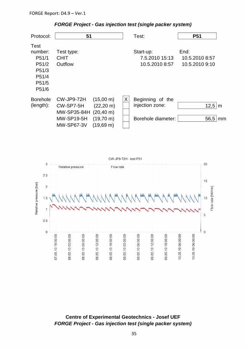
In the next stage of pilot testing a total of 5 long-term injection tests for each of the test boreholes were performed using the single packer system. Each test consisted of a series of pulses formed by CHIT, PDT and the measurement of outflow. Detailed information and graphs based on the tests can be found in the test protocols (Appendix 1). Fig. 16 provides an example of such a test.
The pilot tests carried out in the horizontal boreholes were highly relevant to the environment in which the vertical borehole, used for the detailed field tests (MW-SP67-3V), is located and the results can be used for the future comparison of gas and water permeability, especially those boreholes located in the Mokrsko area: MW-SP35-84H (the same rock formation - granodiorite) and MW-SP19-5H. All the Mokrsko sites have approximately the same height of overburden (about 100 meters). The results of pilot testing in the Celina boreholes will be useful in terms of the study of disturbed zones.

FORGE Report: D4.9 – Ver.1
22
Fig. 16 - Example of pilot test
3.1.4. Field tests The main field tests were conducted in the vertical borehole MW-SP67-3V. This borehole, with an initial depth of 19.69m, was systematically tested using the single packer system. The permeability of individual sections of the borehole was tested depending on the depth of the packer in the borehole during the gas injection process.
Each of the long-term tests consisted of the Constant Head Injection Test and the Pressure Drop Test which was carried out in all cases following the achievement of a steady flow state. The third type of test (measurement of the outflow) was not performed for technical reasons (potential damage of the equipment caused by water back-flux).
Information on the field tests is shown in Tab. 3 and detailed information and graphs based on the tests can be found in the test protocols (Appendix 1).
Tab. 3 - Field tests - borehole MW-SP67-3V
Test number
Beginning of the
injection zone
Borehole length
Test type Start End Test type Start End
F77 10.0 19.7 CHIT 26.11.2010 11.40
2.12.2010 9.23 PDT 2.12.2010
9.23 7.12.2010
7.52
F78 15.0 19.7 CHIT 10.12.2010 12.28
21.12.2010 10.44 PDT 21.12.2010
10.44 6.1.2011 9.00
F79 12.5 19.7 CHIT 6.1.2011 10.00
12.1.2011 7.42 PDT 12.1.2011
7.42 13.1.2011
9.48
F80 7.5 19.7 CHIT 13.1.2011 10.08
18.1.2011 12.51 PDT 18.1.2011
12.51 20.1.2011
9.36
F81 5.0 19.7 CHIT 20.1.2011 10.25
26.1.2011 9.50 PDT 26.1.2011
9.50 26.1.2011
10.54
F82 5.0 19.7 CHIT 3.2.2011 11.40
15.2.2011 9.08 PDT 15.2.2011
9.08 17.2.2011
9.09 F83 2.0 19.7 CHIT 17.2.2011 1.3.2011 PDT 1.3.2011 3.3.2011 9.37

FORGE Report: D4.9 – Ver.1
23
10.13 11.52 11.52
F84 17.5 19.7 CHIT 10.3.2011 13:20:00
18.3.2011 12:04:20 PDT 18.3.2011
12:04:20 22.3.2011
8:55:00
Fig. 17 - Example of CHIT test
Fig. 18 - Example of PDT field test

FORGE Report: D4.9 – Ver.1
24
3.1.5. Tests evaluation The aim of test evaluation was to determine permeability and conductivity on the basis of the data obtained from the CHIT tests. In order to simplify the evaluation, the team considered only the single flow phase, i.e. it was assumed that after a steady flow state in the injection test had been achieved, almost all the water would have been pushed out from the flow field. The team was aware that making such an assumption was not ideal and that it would bring about a number of errors, but in terms of an initial evaluation at this stage of the project it was considered sufficient.
THEORY
The ability of a porous medium to transmit a particular type of fluid depends on the characteristics of both the medium and the fluid. Two terms are commonly used in characterising this ability: permeability and conductivity. Permeability, k, also known as intrinsic permeability, is a function of the medium alone, with a unit of L2 in the SI system, e.g. m2. Conductivity, K (unit LT-1), on the other hand, is a function of both the medium and the fluid.
The relationships between permeability and conductivity are given below:
w
ww
gkKµρ
= (1)
g
gg
gkK
µρ
= (2)
νkgK = (3)
where:
k intrinsic permeability of rock [m2]
Kw hydraulic conductivity of rock [m/s]
Kg gas conductivity [m/s]
ρw density of water [kg/m3]
µw dynamic viscosity of water [kg/(m.s)]
ρg density of gas [kg/m3]
µg dynamic viscosity of gas [kg/(m.s)]
ν kinematic viscosity [m2/s]
g gravity acceleration [m/s2]
MODEL OF FLOW
The permeability and conductivity of the rock mass could be determined based on recorded values of pressure in the borehole and the air flow rate in the steady flow state.
The mathematical model used in the gas injection tests is based on Darcy's Law which characterises the flow of liquids (fluids and gases). In order to determine permeability or gas conductivity on the basis of the measured flow rate under known pressure differences, different formulas regarding analytical solutions of flow distribution in space must be used

FORGE Report: D4.9 – Ver.1
25
depending on the geometric arrangement. Several models can be applied to steady-state flow regime cases.
The first model forms the base case which describes the parallel flow field, such as in a closed cylinder in the direction of its axis or near the borehole (to a depth less than the diameter of the borehole). The total flow rate in the differential form in variants for differing quantities is given by the relationship (4).
pkSpg
KShSKQ ∇=∇=∇=µρ
(4)
where:
Q total flow rate [m3/s]
S cross-section perpendicular to the direction of flow [m2]
K conductivity [m/s]
h piezometric height [m]
ρ fluid density [kg/m3]
g gravity acceleration [m/s2]
p pressure [Pa]
k intrinsic permeability [m2]
μ dynamic viscosity of fluid [kg/m/s=Pa.s]
The same relationship applies to gas in a differential form, but it is necessary in the case of gases for putting the pressure difference within a particular interval (distance) to incorporate compressibility; the simplest approximation is the relationship starting from the fundamental ideal gas equation in which a second power of pressure enters the equation. Gas flow models can be derived analogically on the basis of this relationship.
Radial 2D flow (cylindrical), which was used for the initial determination, expresses a convergent, axi-symmetrical flow field, i.e. a field uniform in all directions, which is expressed in the area of the annulus (Fig. 19). The total flow rate is given by equation (5).
( )µ
π kL
rRp
pQ)ln(0
2∆= (5)
where:
r radius of the inner circle (borehole) [m]
R radius of the outer circle (the distance of theoretically unaffected areas or areas where there is another reason for the pressure being known), also termed the effective radius or radius of influence [m]
L the thickness of the 2D model (in this case it is the length of the borehole section - injection zone) [m]
Δ p difference between pressures [Pa]
P0 reference pressure (atmospheric) [Pa]

FORGE Report: D4.9 – Ver.1
26
Fig. 19 - Radial 2D flow model
This simplified flow model is not required to provide an absolutely precise picture of the complicated conditions within the rock mass and, in this phase of the project, it was decided that the permeability values obtained from the model could be considered precise enough for the purpose.
3.1.6. Results The results of all the Constant Head Injection Tests concerned the determination of the intrinsic permeability and the gas conductivity of borehole injection zones. The results of the pilot tests can be seen in Tab. 4 - Tab. 7. Tab. 8 contains the results of the field tests. The tables include the injection rate and pressure values as well as the temperature of the injected air in the steady flow state needed for evaluation. Colour-graded values of pressure and permeability are shown in Tab. 8. The results of the field tests are also shown schematically for reasons of clarity in Fig. 20.
Tab. 4 - Pilot tests results - borehole CW-JP9-72H
Test number
Injection zone
Injection rate (Q) [Nl/min]
Pressure (P) [bar]
Temperature (T) [°C]
Intrinsic permeability (k)
[m2]
Gas conductivity
(K) [m/s] P42/1 10.0 - 15.0 9.6 0.8 10.8 1.7E-14 1.2E-08 P44/1 14 - 15.0 9.7 1.4 10.6 2.6E-14 1.8E-08 P51/1 12.5 - 15.0 10.1 1.0 10.5 2.2E-14 1.5E-08 P56/1 7.5 - 15.0 10.2 0.4 10.4 5.2E-14 3.6E-08 P65/1 10 - 15.0 9.5 0.6 10.8 3.0E-14 2.0E-08

FORGE Report: D4.9 – Ver.1
27
Tab. 5 - Pilot tests results - borehole CW-SP7-5H
Test number
Injection zone
Injection rate (Q) [Nl/min]
Pressure (P) [bar]
Temperature (T) [°C]
Intrinsic permeability (k)
[m2]
Gas conductivity
(K) [m/s] P57/3 15.0 - 22.2 9.7 2.4 11.4 1.3E-15 8.8E-10 P61/1 5.0 - 22.2 9.8 1.7 11.4 1.1E-15 7.4E-10 P62/1 5.0 - 22.2 10.1 1.7 11.2 1.2E-15 8.0E-10 P63/1 10.0 - 22.2 10.1 2.2 11.3 9.7E-16 6.6E-10 P64/1 10.0 - 22.2 9.9 2.3 11.6 8.6E-16 5.9E-10
Tab. 6 - Pilot tests results - borehole MW-SP35-84H
Test number
Injection zone
Injection rate (Q) [Nl/min]
Pressure (P) [bar]
Temperature (T) [°C]
Intrinsic permeability (k)
[m2]
Gas conductivity
(K) [m/s] P37/1 10.0 - 20.4 6.4 16.7 14.5 1.2E-17 8.2E-12 P39/1 10.0 - 20.4 6.8 14.6 12.5 1.7E-17 1.2E-11 P40/1 10.0 - 20.4 15.4 20.9 11.6 1.9E-17 1.3E-11 P41/1 9.0 - 20.4 7.0 14.5 11.9 1.6E-17 1.1E-11 P76/1 10.0 - 20.4 36.2 27.0 9.1 2.6E-17 1.8E-11
Tab. 7 - Pilot tests results - borehole MW-SP19-5H
Test number
Injection zone
Injection rate (Q) [Nl/min]
Pressure (P) [bar]
Temperature (T) [°C]
Intrinsic permeability (k)
[m2]
Gas conductivity
(K) [m/s] P32/1 5.0 - 19.7 34.9 29.1 8.5 1.5E-17 1.1E-11 P36/1 10.0 - 19.7 11.1 20.3 11.4 1.5E-17 1.0E-11 P66/1 10.0 - 19.7 10.4 19.0 11.6 1.6E-17 1.1E-11 P67/1 10.0 - 19.7 10.3 18.3 11.6 1.7E-17 1.2E-11 P68/1 14.5 - 19.7 9.3 23.9 11.9 1.7E-17 1.2E-11
Tab. 8 - Field tests results - borehole MW-SP67-3V
Test number
Injection zone
Injection rate (Q) [Nl/min]
Pressure (P) [bar]
Temperature (T) [°C]
Intrinsic permeability (k)
[m2]
Gas conductivity
(K) [m/s] F84/1 17.5 - 19.7 35.5 20.8 8.0 2.0E-16 1.4E-10 F78/1 15.0 - 19.7 25.4 18.1 9.3 9.0E-17 6.3E-11 F79/1 12.5 - 19.7 36.1 21.8 7.9 5.8E-17 4.0E-11 F77/1 10.0 - 19.7 35.6 20.4 7.9 4.8E-17 3.4E-11 F80/1 7.5 - 19.7 35.8 21.5 8.1 3.5E-17 2.4E-11 F81/1 5.0 - 19.7 35.8 13.6 7.5 7.2E-17 5.0E-11 F82/1 5.0 - 19.7 35.2 13.3 7.4 7.4E-17 5.2E-11 F83/1 2.0 - 19.7 35.3 9.2 7.6 1.3E-16 9.0E-11

FORGE Report: D4.9 – Ver.1
28
Fig. 20 - Results of the field tests
Bore
hole
MW
-SP6
7-3V
Chai
nage
[m]
1,0
2,0
2,5
3,0
4,0
5,0
6,0
7,0
7,5
8,0
9,0
10,0
11,0
12,0
12,5
13,0
14,0
15,0
16,0
17,0
17,5
18,0
19,0
19,7
35,5
Nl/m
in
2,0E
-16
m2
20,8
bar
36,1
Nl/m
in21
,8 b
ar5,
8E-1
7 m
225,4
Nl/m
in18
,1 b
ar9,
0E-1
7 m
2
9,2
bar
1,3E
-16
m2
35,8
Nl/m
in21
,5 b
ar3,
5E-1
7 m
2
35,5
Nl/m
in13
,5 b
ar7,
3E-1
7 m
2
35,6
Nl/m
in20
,4 b
ar4,
8E-1
7 m
2
35,3
Nl/m
in
FORGE Report: D4.9 – Ver.1
29
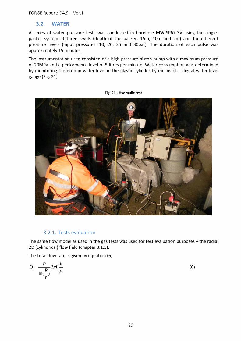
3.2. WATER A series of water pressure tests was conducted in borehole MW-SP67-3V using the single-packer system at three levels (depth of the packer: 15m, 10m and 2m) and for different pressure levels (input pressures: 10, 20, 25 and 30bar). The duration of each pulse was approximately 15 minutes.
The instrumentation used consisted of a high-pressure piston pump with a maximum pressure of 20MPa and a performance level of 5 litres per minute. Water consumption was determined by monitoring the drop in water level in the plastic cylinder by means of a digital water level gauge (Fig. 21).
Fig. 21 - Hydraulic test
3.2.1. Tests evaluation The same flow model as used in the gas tests was used for test evaluation purposes – the radial 2D (cylindrical) flow field (chapter 3.1.5).
The total flow rate is given by equation (6).
µπ kL
rR
PQ 2)ln(
= (6)

FORGE Report: D4.9 – Ver.1
30
3.2.2. Tests results The results of the hydraulic tests are shown in Tab. 9. Intrinsic permeability and hydraulic conductivity were determined for each injection section and pressure level. Fig. 21 shows the dependence of intrinsic permeability on the injection pressure level. A value of pressure around 25 bar, which matches the primary stress level, should coincide with increasing permeability.
Tab. 9 - Water injection tests results
Injection section [m] 15.0 - 19.7
Input pressure level [bar] 10 20 25 30
Testing pressure [bar] 11.75 21.75 26.75 31.75
Injection rate [l/min] 0.06 0.10 0.18 0.27
Injection rate [m3/s] 1.00E-06 1.67E-06 3.00E-06 4.50E-06
Intrinsic permeability [m2] 2.3E-16 2.0E-16 3.0E-16 3.8E-16
Hydraulic conductivity [m/s] 1.7E-09 1.5E-09 2.2E-09 2.8E-09
Injection section [m] 10.0 - 19.7
Input pressure level [bar] 10 20 25 30
Testing pressure [bar] 11.5 21.5 26.5 31.5
Injection rate [l/min] 0.05 0.13 0.20 0.35
Injection rate [m3/s] 8.33E-07 2.17E-06 3.33E-06 5.83E-06
Intrinsic permeability [m2] 1.9E-16 2.7E-16 3.4E-16 4.9E-16
Hydraulic conductivity [m/s] 1.4E-09 2.0E-09 2.5E-09 3.6E-09
Injection section [m] 2.0 - 19.7
Input pressure level [bar] 10 20 25 30
Testing pressure [bar] 11 21 26 31
Injection rate [l/min] 0.08 0.20 0.34 0.64
Injection rate [m3/s] 1.33E-06 3.33E-06 5.67E-06 1.07E-05
Intrinsic permeability [m2] 3.2E-16 4.2E-16 5.8E-16 9.2E-16
Hydraulic conductivity [m/s] 2.4E-09 3.1E-09 4.3E-09 6.7E-09

FORGE Report: D4.9 – Ver.1
31
Fig. 22 - Water injection tests results
Dependence of permeability on injection pressure
0,0E+001,0E-162,0E-163,0E-164,0E-165,0E-166,0E-167,0E-168,0E-169,0E-161,0E-15
0 5 10 15 20 25 30 35Pressure level [bar]
Intri
nsic
per
mea
bilit
y [m
2 ] 15,0 - 19,7 10,0 - 19,7 2,0 - 19,7
rock mass primary stress level

FORGE Report: D4.9 – Ver.1
32
Conclusion The aim of this part of the project was to perform baseline hydraulic measurements in crystalline rock structures. The first pilot tests were conducted in four horizontal boreholes. As the result of WP meeting discussions it was decided to drill an additional vertical borehole. This borehole was used for detailed testing in the granite area of the Josef Underground Facility. This report summarizes the field tests undertaken in this borehole to a depth of 20 metres. The borehole was extended to a total depth of 30 meters following the first phase of testing and the section from a depth of 20 to 30 meters is currently being tested. After the completion of these tests it is planned that the borehole will be further extended to a depth of 40 metres and gas pressure tests will be carried out. For the purposes of comparison of the behaviour of the rock mass with regard to air and water a series of water pressure tests were conducted in the same borehole.
The basic hydraulic characteristics of the local environment were determined based on the results of these initial tests. The characteristics were evaluated for each measured section of the borehole. Both water and gas conductivity were calculated using a simplified flow model.

FORGE Report: D4.9 – Ver.1
33
Appendix 1 Test protocols
PILOT TESTS
BOREHOLE CW-JP9-72H
Centre of Experimental Geotechnics - Josef UEF FORGE Project - Gas injection test (single packer system)
Protocol: 42
Test:
P42 Test
number: Test type:
Start-up:
End: P42/1 CHIT
4.5.2010 14:49
5.5.2010 8:30
P42/2 Outflow
5.5.2010 8:30
5.5.2010 8:42 P42/3
P42/4 P42/5 P42/6
Borehole (length):
CW-JP9-72H (15,00 m) X
Beginning of the injection zone: CW-SP7-5H (22,20 m)
10 m
MW-SP35-84H (20,40 m)
MW-SP19-5H (19,70 m)
Borehole diameter: 56,5 mm
MW-SP67-3V (19,69 m)

FORGE Report: D4.9 – Ver.1
34
Centre of Experimental Geotechnics - Josef UEF FORGE Project - Gas injection test (single packer system)
Protocol: 44
Test:
P44 Test
number: Test type:
Start-up:
End: P44/1 CHIT
5.5.2010 11:14
7.5.2010 9:25
P44/2 Outflow
7.5.2010 9:25
7.5.2010 9:36 P44/3
P44/4 P44/5 P44/6
Borehole (length):
CW-JP9-72H (15,00 m) X
Beginning of the injection zone: CW-SP7-5H (22,20 m)
14 m
MW-SP35-84H (20,40 m)
MW-SP19-5H (19,70 m)
Borehole diameter: 56,5 mm
MW-SP67-3V (19,69 m)
Centre of Experimental Geotechnics - Josef UEF
FORGE Report: D4.9 – Ver.1
35
FORGE Project - Gas injection test (single packer system)
Protocol: 51
Test:
P51 Test
number: Test type:
Start-up:
End: P51/1 CHIT
7.5.2010 15:13
10.5.2010 8:57
P51/2 Outflow
10.5.2010 8:57
10.5.2010 9:10 P51/3
P51/4 P51/5 P51/6
Borehole (length):
CW-JP9-72H (15,00 m) X
Beginning of the injection zone: CW-SP7-5H (22,20 m)
12,5 m
MW-SP35-84H (20,40 m)
MW-SP19-5H (19,70 m)
Borehole diameter: 56,5 mm
MW-SP67-3V (19,69 m)
Centre of Experimental Geotechnics - Josef UEF FORGE Project - Gas injection test (single packer system)

FORGE Report: D4.9 – Ver.1
36
Protocol: 56
Test:
P56 Test
number: Test type:
Start-up:
End: P56/1 CHIT
10.5.2010 14:48
11.5.2010 8:57
P56/2 Outflow
11.5.2010 8:57
11.5.2010 9:29 P56/3
P56/4 P56/5 P56/6
Borehole (length):
CW-JP9-72H (15,00 m) X
Beginning of the injection zone: CW-SP7-5H (22,20 m)
7,5 m
MW-SP35-84H (20,40 m)
MW-SP19-5H (19,70 m)
Borehole diameter: 56,5 mm
MW-SP67-3V (19,69 m)
Centre of Experimental Geotechnics - Josef UEF FORGE Project - Gas injection test (single packer system)

FORGE Report: D4.9 – Ver.1
37
Protocol: 65
Test:
P65 Test
number: Test type:
Start-up:
End: P65/1 CHIT
17.6.2010 10:08
25.6.2010 13:32
P65/2 PDT
25.6.2010 13:32
29.6.2010 8:57 P65/3 CHIT
29.6.2010 8:57
1.7.2010 8:25
P65/4 Outflow
1.7.2010 8:25
1.7.2010 9:10 P65/5
P65/6
Borehole (length):
CW-JP9-72H (15,00 m) X
Beginning of the injection zone: CW-SP7-5H (22,20 m)
10 m
MW-SP35-84H (20,40 m)
MW-SP19-5H (19,70 m)
Borehole diameter: 56,5 mm
MW-SP67-3V (19,69 m)
BOREHOLE CW-SP7-5H
Centre of Experimental Geotechnics - Josef UEF FORGE Project - Gas injection test (single packer system)

FORGE Report: D4.9 – Ver.1
38
Protocol: 57
Test:
P57 Test
number: Test type:
Start-up:
End: P57/1 CHIT
11.5.2010 10:40
11.5.2010 11:54
P57/2 PDT
11.5.2010 11:54
11.5.2010 15:05 P57/3 CHIT
11.5.2010 15:05
12.5.2010 8:09
P57/4 Outflow
12.5.2010 8:09
12.5.2010 10:13 P57/5
P57/6
Borehole (length):
CW-JP9-72H (15,00 m)
Beginning of the injection zone: CW-SP7-5H (22,20 m) X
15 m
MW-SP35-84H (20,40 m)
MW-SP19-5H (19,70 m)
Borehole diameter: 56,5 mm
MW-SP67-3V (19,69 m)
Centre of Experimental Geotechnics - Josef UEF FORGE Project - Gas injection test (single packer system)
Protocol: 61
Test:
P61

FORGE Report: D4.9 – Ver.1
39
Test number: Test type:
Start-up:
End:
P61/1 CHIT
12.5.2010 13:35
16.5.2010 16:33 P61/2
P61/3 P61/4 P61/5 P61/6
Borehole (length):
CW-JP9-72H (15,00 m)
Beginning of the injection zone: CW-SP7-5H (22,20 m) X
5 m
MW-SP35-84H (20,40 m)
MW-SP19-5H (19,70 m)
Borehole diameter: 56,5 mm
MW-SP67-3V (19,69 m)
Centre of Experimental Geotechnics - Josef UEF FORGE Project - Gas injection test (single packer system)
Protocol: 62
Test:
P62

FORGE Report: D4.9 – Ver.1
40
Test number: Test type:
Start-up:
End:
P62/1 CHIT
17.5.2010 14:28
19.5.2010 11:35 P62/2 PDT
19.5.2010 11:35
20.5.2010 9:15
P62/3 P62/4 P62/5 P62/6
Borehole (length):
CW-JP9-72H (15,00 m)
Beginning of the injection zone: CW-SP7-5H (22,20 m) X
5 m
MW-SP35-84H (20,40 m)
MW-SP19-5H (19,70 m)
Borehole diameter: 56,5 mm
MW-SP67-3V (19,69 m)
Centre of Experimental Geotechnics - Josef UEF FORGE Project - Gas injection test (single packer system)
Protocol: 63
Test:
P63

FORGE Report: D4.9 – Ver.1
41
Test number: Test type:
Start-up:
End:
P63/1 CHIT
20.5.2010 9:28
25.5.2010 11:38 P63/2
P63/3 P63/4 P63/5 P63/6
Borehole (length):
CW-JP9-72H (15,00 m)
Beginning of the injection zone: CW-SP7-5H (22,20 m) X
10 m
MW-SP35-84H (20,40 m)
MW-SP19-5H (19,70 m)
Borehole diameter: 56,5 mm
MW-SP67-3V (19,69 m)
Centre of Experimental Geotechnics - Josef UEF FORGE Project - Gas injection test (single packer system)
Protocol: 64
Test:
P64

FORGE Report: D4.9 – Ver.1
42
Test number: Test type:
Start-up:
End:
P64/1 CHIT
28.5.2010 14:25
4.6.2010 10:56 P64/2 PDT
4.6.2010 10:56
7.6.2010 14:26
P64/3 CHIT
7.6.2010 14:26
8.6.2010 12:33 P64/4 Outflow
8.6.2010 12:33
9.6.2010 8:16
P64/5 P64/6
Borehole (length):
CW-JP9-72H (15,00 m)
Beginning of the injection zone: CW-SP7-5H (22,20 m) X
10 m
MW-SP35-84H (20,40 m)
MW-SP19-5H (19,70 m)
Borehole diameter: 56,5 mm
MW-SP67-3V (19,69 m)
BOREHOLE MW-SP35-84H
Centre of Experimental Geotechnics - Josef UEF FORGE Project - Gas injection test (single packer system)

FORGE Report: D4.9 – Ver.1
43
Protocol: 37
Test:
P37 Test
number: Test type:
Start-up:
End: P37/1 CHIT
16.3.2010 14:44
19.3.2010 11:11
P37/2 Outflow
19.3.2010 11:11
19.3.2010 16:20 P37/3
P37/4 P37/5 P37/6
Borehole (length):
CW-JP9-72H (15,00 m)
Beginning of the injection zone: CW-SP7-5H (22,20 m)
10 m
MW-SP35-84H (20,40 m) X
MW-SP19-5H (19,70 m)
Borehole diameter: 56,5 mm
MW-SP67-3V (19,69 m)
Centre of Experimental Geotechnics - Josef UEF FORGE Project - Gas injection test (single packer system)
Protocol: 39
Test:
P39

FORGE Report: D4.9 – Ver.1
44
Test number: Test type:
Start-up:
End:
P39/1 CHIT
8.4.2010 10:23
9.4.2010 9:18 P39/2
P39/3 P39/4 P39/5 P39/6
Borehole (length):
CW-JP9-72H (15,00 m)
Beginning of the injection zone: CW-SP7-5H (22,20 m)
10 m
MW-SP35-84H (20,40 m) X
MW-SP19-5H (19,70 m)
Borehole diameter: 56,5 mm
MW-SP67-3V (19,69 m)
Centre of Experimental Geotechnics - Josef UEF FORGE Project - Gas injection test (single packer system)
Protocol: 40
Test:
P40

FORGE Report: D4.9 – Ver.1
45
Test number: Test type:
Start-up:
End:
P40/1 CHIT
16.4.2010 11:16
23.4.2010 9:20 P40/2 PDT
23.4.2010 9:20
29.4.2010 11:50
P40/3 CHIT
29.4.2010 11:50
3.5.2010 8:25 P40/4 Outflow
3.5.2010 8:25
3.5.2010 13:15
P40/5 P40/6
Borehole (length):
CW-JP9-72H (15,00 m)
Beginning of the injection zone: CW-SP7-5H (22,20 m)
10 m
MW-SP35-84H (20,40 m) X
MW-SP19-5H (19,70 m)
Borehole diameter: 56,5 mm
MW-SP67-3V (19,69 m)
Centre of Experimental Geotechnics - Josef UEF FORGE Project - Gas injection test (single packer system)
Protocol: 41
Test:
P41

FORGE Report: D4.9 – Ver.1
46
Test number: Test type:
Start-up:
End:
P41/1 CHIT
3.5.2010 13:22
4.5.2010 8:56 P41/2 Outflow
4.5.2010 8:56
4.5.2010 9:08
P41/3 P41/4 P41/5 P41/6
Borehole (length):
CW-JP9-72H (15,00 m)
Beginning of the injection zone: CW-SP7-5H (22,20 m)
9 m
MW-SP35-84H (20,40 m) X
MW-SP19-5H (19,70 m)
Borehole diameter: 56,5 mm
MW-SP67-3V (19,69 m)
Centre of Experimental Geotechnics - Josef UEF FORGE Project - Gas injection test (single packer system)
Protocol: 76
Test:
P76

FORGE Report: D4.9 – Ver.1
47
Test number: Test type:
Start-up:
End:
P76/1 CHIT
5.11.2010 12:20
11.11.2010 9:39 P76/2 PDT
11.11.2010 9:39
19.11.2010 10:24
P76/3 CHIT
19.11.2010 10:24
23.11.2010 8:12 P76/4
P76/5 P76/6
Borehole (length):
CW-JP9-72H (15,00 m)
Beginning of the injection zone: CW-SP7-5H (22,20 m)
10 m
MW-SP35-84H (20,40 m) X
MW-SP19-5H (19,70 m)
Borehole diameter: 56,5 mm
MW-SP67-3V (19,69 m)
BOREHOLE MW-SP19-5H
Centre of Experimental Geotechnics - Josef UEF FORGE Project - Gas injection test (single packer system)
Protocol: 32
Test:
P32

FORGE Report: D4.9 – Ver.1
48
Test number: Test type:
Start-up:
End:
P32/1 CHIT
25.2.2010 9:45
26.2.2010 3:17 P32/2
P32/3 P32/4 P32/5 P32/6
Borehole (length):
CW-JP9-72H (15,00 m)
Beginning of the injection zone: CW-SP7-5H (22,20 m)
5 m
MW-SP35-84H (20,40 m)
MW-SP19-5H (19,70 m) X
Borehole diameter: 56,5 mm
MW-SP67-3V (19,69 m)
Centre of Experimental Geotechnics - Josef UEF FORGE Project - Gas injection test (single packer system)
Protocol: 36
Test:
P36 Test
number: Test type:
Start-up:
End:

FORGE Report: D4.9 – Ver.1
49
P36/1 CHIT
9.3.2010 10:15
11.3.2010 10:20 P36/2
P36/3 P36/4 P36/5 P36/6
Borehole (length):
CW-JP9-72H (15,00 m)
Beginning of the injection zone: CW-SP7-5H (22,20 m)
10 m
MW-SP35-84H (20,40 m)
MW-SP19-5H (19,70 m) X
Borehole diameter: 56,5 mm
MW-SP67-3V (19,69 m)
Centre of Experimental Geotechnics - Josef UEF FORGE Project - Gas injection test (single packer system)
Protocol: 66
Test:
P66 Test
number: Test type:
Start-up:
End: P66/1 CHIT
1.7.2010 13:30
8.7.2010 11:25

FORGE Report: D4.9 – Ver.1
50
P66/2 P66/3 P66/4 P66/5 P66/6
Borehole (length):
CW-JP9-72H (15,00 m)
Beginning of the injection zone: CW-SP7-5H (22,20 m)
10 m
MW-SP35-84H (20,40 m)
MW-SP19-5H (19,70 m) X
Borehole diameter: 56,5 mm
MW-SP67-3V (19,69 m)
Centre of Experimental Geotechnics - Josef UEF FORGE Project - Gas injection test (single packer system)
Protocol: 67
Test:
P67 Test
number: Test type:
Start-up:
End: P67/1 CHIT
8.7.2010 11:50
15.7.2010 11:24
P67/2 PDT
15.7.2010 11:24
20.7.2010 11:45 P67/3 CHIT
20.7.2010 11:45
22.7.2010 8:47

FORGE Report: D4.9 – Ver.1
51
P67/4 Outflow
22.7.2010 8:47
22.7.2010 23:42 P67/5
P67/6
Borehole (length):
CW-JP9-72H (15,00 m)
Beginning of the injection zone: CW-SP7-5H (22,20 m)
10 m
MW-SP35-84H (20,40 m)
MW-SP19-5H (19,70 m) X
Borehole diameter: 56,5 mm
MW-SP67-3V (19,69 m)
Centre of Experimental Geotechnics - Josef UEF FORGE Project - Gas injection test (single packer system)
Protocol: 68
Test:
P68 Test
number: Test type:
Start-up:
End: P68/1 CHIT
29.7.2010 14:54
9.8.2100 12:15
P68/2 PDT
9.8.2100 12:15
13.8.2010 13:42 P68/3 CHIT
13.8.2010 13:42
17.8.2010 11:42
P68/4 Outflow
17.8.2010 11:42
18.8.2010 10:11

FORGE Report: D4.9 – Ver.1
52
P68/5 P68/6
Borehole (length):
CW-JP9-72H (15,00 m)
Beginning of the injection zone: CW-SP7-5H (22,20 m)
14,5 m
MW-SP35-84H (20,40 m)
MW-SP19-5H (19,70 m) X
Borehole diameter: 56,5 mm
MW-SP67-3V (19,69 m)

FORGE Report: D4.9 – Ver.1
53
FIELD TESTS
Centre of Experimental Geotechnics - Josef UEF FORGE Project - Gas injection test (single packer system)
Protocol: 77
Test:
F77 Test
number: Test type:
Start-up:
End: F77/1 CHIT
26.11.2010 11:40
2.12.2010 9:23
F77/2 PDT
2.12.2010 9:23
7.12.2010 7:52 F77/3
F77/4 F77/5 F77/6
Borehole (length):
CW-JP9-72H (15,00 m)
Beginning of the injection zone: CW-SP7-5H (22,20 m)
10 m
MW-SP35-84H (20,40 m)
MW-SP19-5H (19,70 m)
Borehole diameter: 56,5 mm
MW-SP67-3V (19,69 m) X

FORGE Report: D4.9 – Ver.1
54

FORGE Report: D4.9 – Ver.1
55
Centre of Experimental Geotechnics - Josef UEF FORGE Project - Gas injection test (single packer system)
Protocol: 78
Test:
F78 Test
number: Test type:
Start-up:
End: F78/1 CHIT
10.12.2010 12:28
21.12.2010 10:44
F78/2 PDT
21.12.2010 10:44
6.1.2011 9:00 F78/3
F78/4 F78/5 F78/6
Borehole (length):
CW-JP9-72H (15,00 m)
Beginning of the injection zone: CW-SP7-5H (22,20 m)
15 m
MW-SP35-84H (20,40 m)
MW-SP19-5H (19,70 m)
Borehole diameter: 56,5 mm
MW-SP67-3V (19,69 m) X

FORGE Report: D4.9 – Ver.1
56

FORGE Report: D4.9 – Ver.1
57
Centre of Experimental Geotechnics - Josef UEF FORGE Project - Gas injection test (single packer system)
Protocol: 79
Test:
F79 Test
number: Test type:
Start-up:
End: F79/1 CHIT
6.1.2011 10:00
12.1.2011 7:42
F79/2 PDT
12.1.2011 7:42
13.1.2011 9:48 F79/3
F79/4 F79/5 F79/6
Borehole (length):
CW-JP9-72H (15,00 m)
Beginning of the injection zone: CW-SP7-5H (22,20 m)
12,5 m
MW-SP35-84H (20,40 m)
MW-SP19-5H (19,70 m)
Borehole diameter: 56,5 mm
MW-SP67-3V (19,69 m) X

FORGE Report: D4.9 – Ver.1
58

FORGE Report: D4.9 – Ver.1
59
Centre of Experimental Geotechnics - Josef UEF FORGE Project - Gas injection test (single packer system)
Protocol: 80
Test:
F80 Test
number: Test type:
Start-up:
End: F80/1 CHIT
13.1.2011 10:08
18.1.2011 12:51
F80/2 PDT
18.1.2011 12:51
20.1.2011 9:36 F80/3
F80/4 F80/5 F80/6
Borehole (length):
CW-JP9-72H (15,00 m)
Beginning of the injection zone: CW-SP7-5H (22,20 m)
7,5 m
MW-SP35-84H (20,40 m)
MW-SP19-5H (19,70 m)
Borehole diameter: 56,5 mm
MW-SP67-3V (19,69 m) X

FORGE Report: D4.9 – Ver.1
60

FORGE Report: D4.9 – Ver.1
61
Centre of Experimental Geotechnics - Josef UEF FORGE Project - Gas injection test (single packer system)
Protocol: 81
Test:
F81 Test
number: Test type:
Start-up:
End: F81/1 CHIT
20.1.2011 10:25
26.1.2011 9:50
F81/2 PDT
26.1.2011 9:50
26.1.2011 10:54 F81/3
F81/4 F81/5 F81/6
Borehole (length):
CW-JP9-72H (15,00 m)
Beginning of the injection zone: CW-SP7-5H (22,20 m)
5 m
MW-SP35-84H (20,40 m)
MW-SP19-5H (19,70 m)
Borehole diameter: 56,5 mm
MW-SP67-3V (19,69 m) X

FORGE Report: D4.9 – Ver.1
62

FORGE Report: D4.9 – Ver.1
63
Centre of Experimental Geotechnics - Josef UEF FORGE Project - Gas injection test (single packer system)
Protocol: 82
Test:
F82 Test
number: Test type:
Start-up:
End: F82/1 CHIT
3.2.2011 11:40
15.2.2011 9:08
F82/2 PDT
15.2.2011 9:08
17.2.2011 9:09 F82/3
F82/4 F82/5 F82/6
Borehole (length):
CW-JP9-72H (15,00 m)
Beginning of the injection zone: CW-SP7-5H (22,20 m)
5 m
MW-SP35-84H (20,40 m)
MW-SP19-5H (19,70 m)
Borehole diameter: 56,5 mm
MW-SP67-3V (19,69 m) X

FORGE Report: D4.9 – Ver.1
64

FORGE Report: D4.9 – Ver.1
65
Centre of Experimental Geotechnics - Josef UEF FORGE Project - Gas injection test (single packer system)
Protocol: 83
Test:
F83 Test
number: Test type:
Start-up:
End: F83/1 CHIT
17.2.2011 10:13
1.3.2011 11:52
F83/2 PDT
1.3.2011 11:52
3.3.2011 9:37 F83/3
F83/4 F83/5 F83/6
Borehole (length):
CW-JP9-72H (15,00 m)
Beginning of the injection zone: CW-SP7-5H (22,20 m)
2 m
MW-SP35-84H (20,40 m)
MW-SP19-5H (19,70 m)
Borehole diameter: 56,5 mm
MW-SP67-3V (19,69 m) X

FORGE Report: D4.9 – Ver.1
66

FORGE Report: D4.9 – Ver.1
67
Centre of Experimental Geotechnics - Josef UEF FORGE Project - Gas injection test (single packer system)
Protocol: 84
Test:
F84 Test
number: Test type:
Start-up:
End: F84/1 CHIT
10.3.2011 13:20
18.3.2011 12:04
F84/2 PDT
18.3.2011 12:04
22.3.2011 8:55 F84/3
F84/4 F84/5 F84/6
Borehole (length):
CW-JP9-72H (15,00 m)
Beginning of the injection zone: CW-SP7-5H (22,20 m)
17,5 m
MW-SP35-84H (20,40 m)
MW-SP19-5H (19,70 m)
Borehole diameter: 56,5 mm
MW-SP67-3V (19,69 m) X

FORGE Report: D4.9 – Ver.1
68

FORGE Report: D4.9 – Ver.1
69
4. References MORÁVEK, P. 1996. The Mokrsko Gold Deposit. Gold Deposits in Bohemia, Prague: Czech Geological Survey
RockMass AS. 2011. Spreadsheet for RMR-Q-RMi, Available: http://rockmass.net/.