Base software and HMI Advanced - Commissioning … · Programming PLC Functions 4 Diagnostics and...
674
Preface HMI Advanced 1 Expanding the user interface 2 Online help 3 Creating target language texts 4 PCU Basesoftware V8.0 5 PCU Basesoftware V7.6 6 Appendix A SINUMERIK 840Di sl/840D sl SINUMERIK 810D/840D Base software and HMI Advanced Commissioning Manual 11/2006 6FC5397-0DP10-0BA0 Valid for: SINUMERIK 840D sl/840DE sl SINUMERIK 840Di sl/840DiE sl SINUMERIK 840D/840DE SINUMERIK 810D/810DE controllers Software version: HMI Advanced V7.3
Transcript of Base software and HMI Advanced - Commissioning … · Programming PLC Functions 4 Diagnostics and...
Preface
HMI Advanced 1
Expanding the user interface 2
Online help 3
Creating target language texts
4
PCU Basesoftware V8.0 5
PCU Basesoftware V7.6 6
Appendix A
SINUMERIK 840Di sl/840D sl SINUMERIK 810D/840D Base software and HMI Advanced
Commissioning Manual
11/2006 6FC5397-0DP10-0BA0
Valid for: SINUMERIK 840D sl/840DE sl SINUMERIK 840Di sl/840DiE sl SINUMERIK 840D/840DE SINUMERIK 810D/810DE controllers Software version: HMI Advanced V7.3
Safety Guidelines This manual contains notices you have to observe in order to ensure your personal safety, as well as to prevent damage to property. The notices referring to your personal safety are highlighted in the manual by a safety alert symbol, notices referring only to property damage have no safety alert symbol. These notices shown below are graded according to the degree of danger.
Danger
indicates that death or severe personal injury will result if proper precautions are not taken.
Warning
indicates that death or severe personal injury may result if proper precautions are not taken.
Caution
with a safety alert symbol, indicates that minor personal injury can result if proper precautions are not taken.
Caution
without a safety alert symbol, indicates that property damage can result if proper precautions are not taken.
Notice
indicates that an unintended result or situation can occur if the corresponding information is not taken into account.
If more than one degree of danger is present, the warning notice representing the highest degree of danger will be used. A notice warning of injury to persons with a safety alert symbol may also include a warning relating to property damage.
Qualified Personnel The device/system may only be set up and used in conjunction with this documentation. Commissioning and operation of a device/system may only be performed by qualified personnel. Within the context of the safety notes in this documentation qualified persons are defined as persons who are authorized to commission, ground and label devices, systems and circuits in accordance with established safety practices and standards.
Prescribed Usage Note the following:
Warning
This device may only be used for the applications described in the catalog or the technical description and only in connection with devices or components from other manufacturers which have been approved or recommended by Siemens. Correct, reliable operation of the product requires proper transport, storage, positioning and assembly as well as careful operation and maintenance.
Trademarks All names identified by ® are registered trademarks of the Siemens AG. The remaining trademarks in this publication may be trademarks whose use by third parties for their own purposes could violate the rights of the owner.
Disclaimer of Liability We have reviewed the contents of this publication to ensure consistency with the hardware and software described. Since variance cannot be precluded entirely, we cannot guarantee full consistency. However, the information in this publication is reviewed regularly and any necessary corrections are included in subsequent editions.
Siemens AG Automation and Drives Postfach 48 48 90437 NÜRNBERG GERMANY
Order No.: 6FC5397-0DP10-0BA0 Ⓟ 02/2007
Copyright © Siemens AG 2006. Technical data subject to change

Base software and HMI Advanced Commissioning Manual, 11/2006, 6FC5397-0DP10-0BA0 3
Preface
SINUMERIK documentation The SINUMERIK documentation is organized in 3 parts: • General documentation • User documentation • Manufacturer/Service documentation An overview of publications, which is updated monthly and also provides information about the language versions available, can be found on the Internet at: http://www.siemens.com/motioncontrol Select the menu items "Support" → "Technical Documentation" → "Overview of Publications". The Internet version of DOConCD (DOConWEB) is available at: http://www.automation.siemens.com/doconweb Information about training courses and FAQs (Frequently Asked Questions) can be found at the following website: http://www.siemens.com/motioncontrol under "Support".
Target group This documentation is intended for service personnel. The plant/product is installed, connected, and ready to start. The Commissioning Manual ought to contain all necessary information about or at least references to subsequent procedures such as testing the cabling, power on and functional testing.
Benefits The intended target group can use the Commissioning Manual to test and commission the product/system correctly and in total safety. Utilization phase: Setup and commissioning phase
Standard scope This documentation only describes the functionality of the standard version. Additions or revisions made by the machine manufacturer are documented by the machine manufacturer. Other functions not described in this documentation might be executable in the control. However, no claim can be made regarding the availability of these functions when the equipment is first supplied or in the event of servicing.
Preface
Base software and HMI Advanced 4 Commissioning Manual, 11/2006, 6FC5397-0DP10-0BA0
For the sake of simplicity, this documentation does not contain all detailed information about all types of the product and cannot cover every conceivable case of installation, operation, or maintenance.
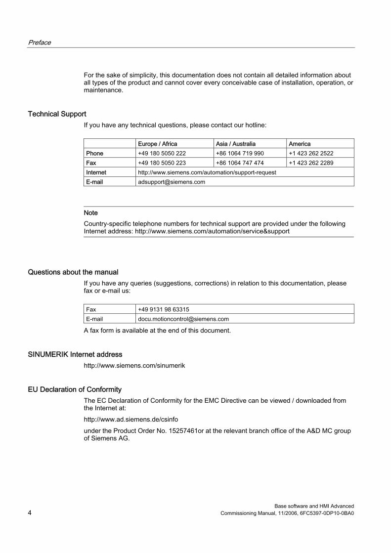
Technical Support If you have any technical questions, please contact our hotline:
Europe / Africa Asia / Australia America Phone +49 180 5050 222 +86 1064 719 990 +1 423 262 2522 Fax +49 180 5050 223 +86 1064 747 474 +1 423 262 2289 Internet http://www.siemens.com/automation/support-request E-mail [email protected]
Note Country-specific telephone numbers for technical support are provided under the following Internet address: http://www.siemens.com/automation/service&support
Questions about the manual If you have any queries (suggestions, corrections) in relation to this documentation, please fax or e-mail us:
Fax +49 9131 98 63315 E-mail [email protected]
A fax form is available at the end of this document.
SINUMERIK Internet address http://www.siemens.com/sinumerik
EU Declaration of Conformity The EC Declaration of Conformity for the EMC Directive can be viewed / downloaded from the Internet at: http://www.ad.siemens.de/csinfo under the Product Order No. 15257461or at the relevant branch office of the A&D MC group of Siemens AG.

Introduction 1
Configuring the HMI system 2
Parameterizing machine data
3
Programming PLC Functions 4
Diagnostics and service 5
List of the INI Files A
List of Abbreviations B
SINUMERIK 840Di sl/840D sl SINUMERIK 810D/840D HMI-Advanced
Commissioning Manual
11/2006 6FC5397-0DP10-0BA0

Safety Guidelines This manual contains notices you have to observe in order to ensure your personal safety, as well as to prevent damage to property. The notices referring to your personal safety are highlighted in the manual by a safety alert symbol, notices referring only to property damage have no safety alert symbol. These notices shown below are graded according to the degree of danger.
Danger
indicates that death or severe personal injury will result if proper precautions are not taken.
Warning
indicates that death or severe personal injury may result if proper precautions are not taken.
Caution
with a safety alert symbol, indicates that minor personal injury can result if proper precautions are not taken.
Caution
without a safety alert symbol, indicates that property damage can result if proper precautions are not taken.
Notice
indicates that an unintended result or situation can occur if the corresponding information is not taken into account.
If more than one degree of danger is present, the warning notice representing the highest degree of danger will be used. A notice warning of injury to persons with a safety alert symbol may also include a warning relating to property damage.
Qualified Personnel The device/system may only be set up and used in conjunction with this documentation. Commissioning and operation of a device/system may only be performed by qualified personnel. Within the context of the safety notes in this documentation qualified persons are defined as persons who are authorized to commission, ground and label devices, systems and circuits in accordance with established safety practices and standards.
Prescribed Usage Note the following:
Warning
This device may only be used for the applications described in the catalog or the technical description and only in connection with devices or components from other manufacturers which have been approved or recommended by Siemens. Correct, reliable operation of the product requires proper transport, storage, positioning and assembly as well as careful operation and maintenance.
Trademarks All names identified by ® are registered trademarks of the Siemens AG. The remaining trademarks in this publication may be trademarks whose use by third parties for their own purposes could violate the rights of the owner.
Disclaimer of Liability We have reviewed the contents of this publication to ensure consistency with the hardware and software described. Since variance cannot be precluded entirely, we cannot guarantee full consistency. However, the information in this publication is reviewed regularly and any necessary corrections are included in subsequent editions.
Siemens AG Automation and Drives Postfach 48 48 90437 NÜRNBERG GERMANY
Order No.: 6FC5397-0DP10-0BA0 Ⓟ 01/2007
Copyright © Siemens AG 2006. Technical data subject to change

HMI-Advanced Commissioning Manual, 11/2006, 6FC5397-0DP10-0BA0 3
Table of contents 1 Introduction................................................................................................................................................ 7
1.1 State of the system when supplied ................................................................................................7 1.2 Booting ...........................................................................................................................................8 1.2.1 Settings at the HMI ........................................................................................................................8 1.2.2 System settings............................................................................................................................10 1.2.3 Behavior of the keys for the PCU.................................................................................................12 1.3 Protection level concept...............................................................................................................13 1.4 Limits of data management..........................................................................................................15 1.5 Licenses .......................................................................................................................................16
2 Configuring the HMI system..................................................................................................................... 19 2.1 Processing INI files ......................................................................................................................19 2.1.1 Terminate OEM commissioning...................................................................................................22 2.1.2 Activating the screensaver...........................................................................................................23 2.1.3 Configuring the prompt dialog box for the EXIT mode ................................................................24 2.1.4 Setting the memory space for the alarm log ................................................................................24 2.1.5 Configuring the acknowledgement icon for PLC alarms..............................................................26 2.1.6 Changing access authorization levels for programs....................................................................27 2.1.7 Configuring the '"Language Selection" softkey............................................................................28 2.1.8 Creating user operator menus .....................................................................................................29 2.1.9 Supplementing service displays on a user-specific basis............................................................36 2.1.10 Creating technology-specific texts ...............................................................................................40 2.1.11 Set-up workpieces with job lists ...................................................................................................42 2.1.12 Using double channel displays ....................................................................................................43 2.1.13 Tool management (WZV).............................................................................................................44 2.1.14 Tool selection without tool management .....................................................................................45 2.1.15 Executing from the hard disk (m:n configuration) ........................................................................47 2.2 Connecting network drives...........................................................................................................49 2.2.1 Setting up access to external drives or computers ......................................................................49 2.2.2 Connecting Drives with Display Machine Data ............................................................................49 2.2.3 Connecting logical drives .............................................................................................................51 2.3 Optimizing simulation...................................................................................................................56 2.3.1 Display of the simulation files.......................................................................................................56 2.3.2 Data match of the simulation .......................................................................................................57 2.3.3 Speeding up the simulation boot..................................................................................................61 2.3.4 Expanding geometrical tool data..................................................................................................62 2.3.5 Optimizing the memory requirement............................................................................................64 2.4 Creating user alarms....................................................................................................................66 2.4.1 Structure of user-specific alarms .................................................................................................66 2.4.2 Creating user-specific alarm texts................................................................................................69
Table of contents
HMI-Advanced 4 Commissioning Manual, 11/2006, 6FC5397-0DP10-0BA0
3 Parameterizing machine data .................................................................................................................. 71 3.1 Handling machine data via the HMI ............................................................................................ 71 3.1.1 Setting-up a display filter for machine data................................................................................. 73 3.1.2 Creating user views..................................................................................................................... 75 3.2 Parameterizing the control using machine data.......................................................................... 77 3.2.1 Fine work offset and base offset ................................................................................................. 77 3.2.2 Machine data for setting actual value, scratching, PRESET ...................................................... 78 3.2.3 Set tool offset to be active immediately ...................................................................................... 79 3.2.4 Specifying the machine and rotary axis position......................................................................... 80 3.2.5 Memory for cycles in the DRAM.................................................................................................. 80 3.2.6 Redefining protection levels for NC data .................................................................................... 82 3.2.7 Change access authorization for softkey "Basis WO" ................................................................ 83 3.2.8 Hiding axes ................................................................................................................................. 84 3.2.9 Representing the spindle utilization ............................................................................................ 85 3.2.10 Inverting the spindle icon of the spindle display ......................................................................... 88 3.3 Creating plain text for PLC machine data ................................................................................... 89
4 Programming PLC Functions................................................................................................................... 91 4.1 Activating the data transfer between the PLC and NCK............................................................. 91 4.2 Transferring the actual task number of the HMI to the PLC ....................................................... 94 4.3 Channel/spindle selection via the PLC ....................................................................................... 96 4.4 Configuring the display of messages in the header.................................................................... 97 4.5 Starting a block search across several channels...................................................................... 100 4.6 Cross-channel status display .................................................................................................... 102 4.7 User status display (OEM) ........................................................................................................ 107
5 Diagnostics and service......................................................................................................................... 111 5.1 Installing HMI software on a PG/PC ......................................................................................... 111 5.1.1 NCU Connection Wizard........................................................................................................... 112 5.1.2 Starting HMI-Advanced in a separate desktop ......................................................................... 113 5.1.3 Configuring the desktop switch application............................................................................... 115 5.1.4 Operating the desktop switch application ................................................................................. 116 5.2 Displaying versions ................................................................................................................... 118 5.3 Setting-up and upgrading the system ....................................................................................... 119 5.3.1 Series commissioning ............................................................................................................... 119 5.3.2 Upgrading the PLC.................................................................................................................... 121 5.3.3 Example: Upgrading the PLC.................................................................................................... 124 5.4 Service displays ........................................................................................................................ 126 5.4.1 Service, axis/spindle ................................................................................................................. 127 5.4.2 Displaying system resources .................................................................................................... 128 5.4.3 Output of configuration data...................................................................................................... 128 5.4.4 Communication error log........................................................................................................... 128 5.5 Action log................................................................................................................................... 129 5.5.1 Setting the action log................................................................................................................. 129 5.5.2 Structure of the log file .............................................................................................................. 132 5.5.3 Saving the log file...................................................................................................................... 134

Table of contents
HMI-Advanced Commissioning Manual, 11/2006, 6FC5397-0DP10-0BA0 5
5.6 HMI Analyzer..............................................................................................................................135 5.6.1 Using the HMI Analyzer .............................................................................................................135 5.6.2 Using the HMI Analyzer .............................................................................................................136 5.6.3 Analyzing INI Files .....................................................................................................................138 5.6.4 Application Examples.................................................................................................................140
A List of the INI Files ................................................................................................................................. 145 A.1 ACTLOG.INI...............................................................................................................................146 A.2 AEDITOR.INI..............................................................................................................................147 A.3 DINO.INI.....................................................................................................................................148 A.4 DG.INI ........................................................................................................................................149 A.5 DGOVW.INI................................................................................................................................150 A.6 DH.INI ........................................................................................................................................151 A.7 DPDH.INI ...................................................................................................................................151 A.8 DPSIM.INI ..................................................................................................................................151 A.9 HEADER.INI...............................................................................................................................152 A.10 HMIDESK.INI .............................................................................................................................156 A.11 IB.INI ..........................................................................................................................................157 A.12 IF.INI ..........................................................................................................................................158 A.13 KEYS.INI ....................................................................................................................................159 A.14 LOGDRIVE.INI ...........................................................................................................................159 A.15 MACHINE.INI .............................................................................................................................162 A.16 MBDDE.INI.................................................................................................................................165 A.17 MMC.INI .....................................................................................................................................169 A.18 NETNAMES.INI .........................................................................................................................174 A.19 OEMFRAME.INI.........................................................................................................................177 A.20 PARAM.INI.................................................................................................................................177 A.21 PARAMTM.INI............................................................................................................................178 A.22 REGIE.INI ..................................................................................................................................178 A.23 SEDITOR.INI..............................................................................................................................180 A.24 SIMTOGEO.INI ..........................................................................................................................187 A.25 TASKCONF.INI ..........................................................................................................................189
B List of Abbreviations .............................................................................................................................. 191 B.1 Abbreviations .............................................................................................................................191
Index...................................................................................................................................................... 195

Table of contents
HMI-Advanced 6 Commissioning Manual, 11/2006, 6FC5397-0DP10-0BA0
Tables
Table 2-1 Assignment of the tasks and softkey texts.................................................................................. 34 Table 2-2 Languages and ANSI tables / code pages used......................................................................... 67 Table 2-3 ANSI table 1250 (Central Europe) .............................................................................................. 67 Table 2-4 Ansi table 1251 (Cyrillic) ............................................................................................................. 67 Table 2-5 ANSI table 1252 (West Europe).................................................................................................. 68 Table 2-6 ANSI table 1254 (Turkish)).......................................................................................................... 68 Table 4-1 User PLC-DB interface................................................................................................................ 98
HMI-Advanced Commissioning Manual, 11/2006, 6FC5397-0DP10-0BA0 7
Introduction 11.1 State of the system when supplied
Overview This manual describes the commissioning of the HMI-Advanced software. When commissioning the SINUMERIK control, you may require additional manuals: • Operator Components and Networking • Commissioning Manual PCU Basic Software • Diagnostics Manual • Parameter Manual • Function Manual Basic Functions
Additional information on special NCK, HMI, PLC or drive functions are provided in the Function Manuals.
Software Depending on the order details, the HMI-Advanced software may be loaded on the PCU 50.3 at the time of delivery. If the HMI-Advanced software is not pre-loaded on the PCU 50.3 (e.g. PCU 50.3 is supplied without system software), the HMI software can be installed on the PCU 50.3 from the CD through Service Center. To install the HMI-Advanced software on the PCU 50.3, you need the following: • PC or PG with CD drive • Network connection • USB memory The HMI-Advanced software can run on the Windows XP operating system.
Notice Installing on a PC/PG: HMI-Advanced can then only be run under a non-administrator user, if this user has write authorization for directory mmc2 of HMI-Advanced. The installation of HMI-Advanced does not provide this authorization.
Introduction 1.2 Booting
HMI-Advanced 8 Commissioning Manual, 11/2006, 6FC5397-0DP10-0BA0
1.2 Booting
1.2.1 Settings at the HMI Individual settings are made and saved under the "HMI" softkey.
Languages Using this function, you select the first and second language; you can toggle using the "Change Language" softkey between the following standard languages: • German • English • French • Italian • Spanish • Simplified Chinese
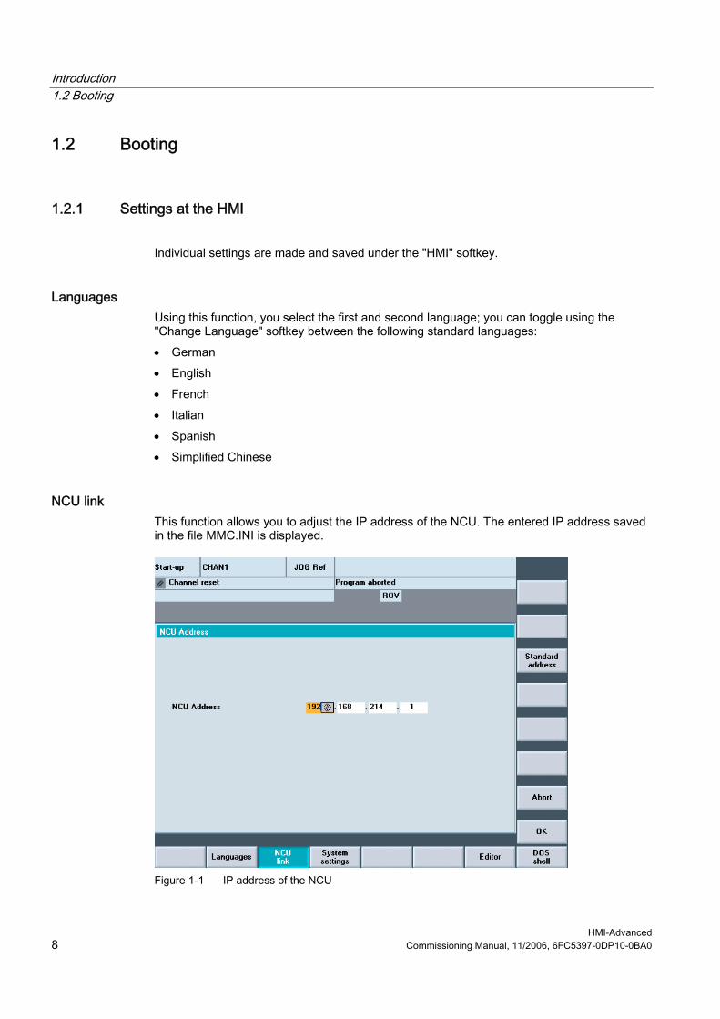
NCU link This function allows you to adjust the IP address of the NCU. The entered IP address saved in the file MMC.INI is displayed.
Figure 1-1 IP address of the NCU
Introduction 1.2 Booting
HMI-Advanced Commissioning Manual, 11/2006, 6FC5397-0DP10-0BA0 9
The NCU is supplied from the factory with the default address 192.168.214.1. In the case of a 1:1 link, this address can be maintained without the need for additional networking. Pressing the “Default address” softkey transfers the factory set IP address 192.168.214.1 to the address field for the NCU. However, if the control is linked to a company network, for example, the IP addresses will be different. You must restart the HMI for the changes to take effect. The section with the new IP address is written to user/mmc.ini.
Error when booting The following error can occur while booting: Alarm 120202: Waiting for a connection to the NC/PLC
Explanation: The operator panel is connected with the NC and PLC via a serial bus.
This alarm occurs if the MMC is started for the first time and the NC/PLC has not yet finished booting or communication with these components is faulty. When this alarm occurs, all display values connected with NC/PLC become invalid. Such faults are normal while the controls are starting up (e.g. after resetting).
Remedy: The alarm disappears automatically as soon as the fault situation is resolved. If the alarm continues, a wide variety of causes may be to blame (e.g. open circuit, NC/PLC not booted, incorrect address/baud rate configuration on one of the bus nodes, ... ).
Responses: --
System settings See the next chapter, System settings.
Printer selection The softkey only works if at least one printer is installed under Windows. It can be used to print displays or data from the commissioning operating area. You can use the <SELECT> button to choose which of the installed printers should be used for output. Default: Output as bitmap file
Editor This key opens the ASCII editor in which files can be edited at DOS level. You can select existing drives via the vertical softkeys.
See also Creating user-specific alarm texts (Page 69)

Introduction 1.2 Booting
HMI-Advanced 10 Commissioning Manual, 11/2006, 6FC5397-0DP10-0BA0
1.2.2 System settings
Overview Under "System settings", settings are made for inquiry windows, file tree display and screen display in the Machine, Program and Services operating areas.
File display You can set the file tree display for the Services, Machine and Program operating areas. The following columns can be selected: • File type (extension) • Downloaded • Length • Access protection • Date • Time • Enable • Display levels (branch to directory trees, max. 7) • Name length (max. 25 characters)
Sorting information A dialog box is displayed for setting the sorting sequence of one column. The defined sequence applies when displaying the corresponding window in the Machine, Program and Services operating areas of the selected column. You can select from the following sort criteria: • Without sorting: Sorted in ascending order according to "Name" by default. • One of the column designations: The sorting sequence runs in ascending or descending
order. Confirm with OK. The sorting sequence set is shown as an arrow symbol next to the name of the column selected as the sorting criterion. In HMI-Advanced with an optional mouse, the following operating options are also available for column sorting: A click on the column name with the arrow symbol changes the direction and sorts the information accordingly. A click on another column makes this the sorting criterion. Click again to change the direction, if necessary, as in (1.). The selection of another sorting criterion in the operating area changes the sorting criterion for all operating areas (Machine, Program, Services).
Introduction 1.2 Booting
HMI-Advanced Commissioning Manual, 11/2006, 6FC5397-0DP10-0BA0 11
Note When the sorting sequence is set, if the sorting criterion is not available in the display image of the operating area, the information is sorted in ascending order according to the column name. The sorting sequence defined in the dialog applies to the operating areas, in which the criterion set in the dialog appears.
System queries You can specify whether or not an inquiry window should be displayed after certain commands, e.g. Delete. Request acknowledgement: • Deleting data/programs, • Deleting directories, • Overwriting files. The "Representation of keys in displays..." window is opened: Here you can define whether keys must be represented as icons or as text in HMI displays. Example: Operator panel front in US layout
Use workpiece templates When creating a new workpiece, you can specify here whether templates should be transferred to the new workpiece (directory): • Job lists • Part programs • Initialization programs
Trace In the event of communication errors, a trace log for communication processes can be recorded following an instruction to the Service department or to our hotline. The trace log is only evaluated by Siemens.
HMI exit mode During the commissioning phase it is often necessary to shut down the HMI-Advanced and operating system and then reboot the PCU. To avoid powering-down and powering-up the PCU or machine, select “Automatically reboot control on shutdown”.
See also Configuring the prompt dialog box for the EXIT mode (Page 24)

Introduction 1.2 Booting
HMI-Advanced 12 Commissioning Manual, 11/2006, 6FC5397-0DP10-0BA0
1.2.3 Behavior of the keys for the PCU
CAPSLOCK The CAPSLOCK function allows all entries made with external SINUMERIK keyboards to be in upper case instead of lower case. If lower case letters are needed, they can be added by means of the SHIFT commands function. This function is only active when HMI-Advanced is running. It is not active in operation with Windows NT/XP.
Restrictions When the CAPSLOCK function is activated, the <SHIFT> key has no effect on letter keys. As is the case in standard Windows applications, CTRL/ALT key sequences only work in lower case mode. Switching to lower case mode is not available on keyboards that are integrated in the OP. The <CTRL> + <SHIFT> switching sequence only works with external PS2 keyboards and USB PC keyboards, not with panel keyboards.
Note The OP keyboard enters lower case text if CAPSLOCK is set on an external keyboard. If the external keyboard is unplugged in this state, the CAPSLOCK mode cannot be cancelled. The <CAPSLOCK> and <NUMLOCK> keys can be filtered by a corresponding setting in parameter file E:\Windows\System.ini. The default setting for CAPSLOCK and NUMLOCK is not filtered.
Activation This function is activated by display MD 9009: $MM_KEYBOARD_STATE
0: CAPSLOCK off 2: CAPSLOCK on
This display MD is only evaluated when booting. If the machine data is changed, the new setting only becomes effective after booting. The display MD 9009 is set to "CAPSLOCK on" and you want to enter lower case letters: 1. Press <CTRL> + <SHIFT> keys to switch to lower case letters. 2. To reset text entry from lower case back to upper case, press <CTRL> + <SHIFT> again.

Introduction 1.3 Protection level concept
HMI-Advanced Commissioning Manual, 11/2006, 6FC5397-0DP10-0BA0 13
1.3 Protection level concept
Overview The protection level concept controls the access to functions and data areas. Protection levels 0 to 7 are available, where 0 represents the highest protection level and 7 the lowest protection level. Protection levels 0 to 3 are locked using a password and 4 to 7 by the appropriate key-operated switch settings.
Protection level
Locked by Area
0 Password Siemens 1 Password Machine manufacturer 2 Password Commissioning engineer, service 3 Password End user 4 Key-operated switch setting 3 Programmer, machine setter 5 Key-operated switch setting 2 Qualified operator 6 Key-operated switch setting 1 Trained operator 7 Key-operated switch setting 0 Semi-skilled operator
The password remains valid until it is reset with the "Delete Password" softkey. The password for protection level 0 provides access to all data areas. The passwords can be changed after activation. If the passwords have been forgotten, for example, the system must be reinitialized (NCK general reset). This resets all passwords to the standard for this software version. POWER ON does not reset the password.
Key-operated switch Protection levels 4 to 7 require a corresponding key-operated switch setting on the machine control panel. Three keys of different colors are provided for this purpose. Each of these keys provides access only to certain areas. The associated interface signals are located in DB10.DBB56. Significance of the key-operated switch settings:
Protection level Switch setting Key color
7 0 = Key removal position No key inserted 6-7 0 and 1 Black 5-7 0 to 2 Green 4-7 0 to 3 Red
Authorization The operator only has access to information corresponding to this particular protection level and the levels below it. Machine data are routinely assigned different protection levels.

Introduction 1.3 Protection level concept
HMI-Advanced 14 Commissioning Manual, 11/2006, 6FC5397-0DP10-0BA0
Protection level 4 (key-operated switch setting 3) is the minimum level required to display machine data. When commissioning the system, the manufacturer password "SUNRISE" should be generally used.
Changing the password Procedure: 1. Press the "Password" softkey. 2. Press the "Set password" softkey. 3. The input window is displayed "Please enter password" 4. Enter one of the three possible passwords and press the Enter key or icon to
acknowledge. A permissible password is acknowledged as set and the currently applicable access level is displayed. Invalid passwords will be rejected. You must delete the old password before activating a password for a lower access level than the one activated.
5. Press the "Delete password" softkey. 6. After pressing the "Delete password" softkey the valid password is deleted and deletion is
acknowledged. The currently valid access level: Key-operated switch setting 0 is set. 7. If a password is already set, then you can change it as follows. Press the "Change
password" softkey. The "Change password" input box appears:
Figure 1-2 Changing the password
8. The modified password must be entered in both input fields then confirmed by pressing the "OK" softkey. Both entered passwords must match for the modified password to become valid.

Introduction 1.4 Limits of data management
HMI-Advanced Commissioning Manual, 11/2006, 6FC5397-0DP10-0BA0 15
1.4 Limits of data management
Overview Data are stored in the following directories: • Workpieces • Part programs • Subroutines • User cycles • Standard cycles • Manufacturer cycles The data management directories can contain a combined total of 100,000 files, whereby each directory (each *.WPD workpiece directory for workpieces) is limited to 1000 files. Files in other directories do not count toward the total limit of 100,000 files. However, each of these directories is also limited to 1000 files, e.g. a maximum of 1000 archives in the archive directory. The following limit applies to network drives: maximum of 1000 files per directory. In practice, the number of files available also depends on the file sizes and the available memory space. A large number of files slows down the display generation for directory displays. A total of 5000 customized alarms or messages can be created in each language.

Introduction 1.5 Licenses
HMI-Advanced 16 Commissioning Manual, 11/2006, 6FC5397-0DP10-0BA0
1.5 Licenses
Overview The HMI-Advanced options manager provides support for the entry of License Key for the existing options. The following summary is displayed:
Figure 1-3 Licenses overview
All options All of the options selectable for this control are listed here. Furthermore, the list states whether or not a valid and adequate license key has already been entered and how many licenses are available.
Missing licenses This displays the options that are already set, which are in the current license key but not yet licensed. In HMI the options are only checked when booting. Consequently, HMI must be rebooted in each case.
Process After input of a license key, the "Accept" softkey is activated. After you have pressed the "Accept" softkey, the license key is written into the NCK where it is checked for validity.

Introduction 1.5 Licenses
HMI-Advanced Commissioning Manual, 11/2006, 6FC5397-0DP10-0BA0 17
If you have entered an invalid license key it will be rejected by the NCK and a message will appear. If an incorrect license key is entered on three occasions, an NCK power-on/reset is required.
Note In NCK the need for a power ON/Reset depends on the procedure when commissioning: If the option bit is first set and then the function is commissioned, then a reset is required after commissioning. However, if the function is commissioned first, a reset initiated and then the options bit is set in the options manager, a reset must be carried out again to activate the changes. No reset is required after writing the license key, the "License key set!" message appears in the user response line.
References: Manual SINUMERIK 840Di sl, Chapter "Automation License Manager"

Introduction 1.5 Licenses
HMI-Advanced 18 Commissioning Manual, 11/2006, 6FC5397-0DP10-0BA0
HMI-Advanced Commissioning Manual, 11/2006, 6FC5397-0DP10-0BA0 19
Configuring the HMI system 22.1 Processing INI files
Notation
[xxx] ;Designating a section Identifier=value ;Value assignment Identifier=<empty> ;Delete value , ;Separator (comma) for multiple assignments ; ;Introduction of comment: As a general rule, comments indicate
the range of values REM ;Introduction of comment
Directory structure The system directory structure is organized in such a way that user changes are retained if the software is upgraded. • User changes to the original software are made in parallel directories. • There is a clear separation between standard HMI software and customer-specific
enhancements. • The "mmc2" and "hmi_adv" directories (and their subdirectories) should be read-only
directories. They contain the original software supplied. These directories are overwritten only if the software is upgraded.
The diagram below shows the priority sequence. This means that: Entries in the directory to the right overwrite corresponding entries in directories to the left.

Configuring the HMI system 2.1 Processing INI files
HMI-Advanced 20 Commissioning Manual, 11/2006, 6FC5397-0DP10-0BA0
Figure 2-1 Priority
Contents of the directories As a general rule, only entries that differ from the originals in mmc2 should be stored in the parallel directories for mmc2.
Notice None of the INI files in the "mmc2" and "hmi_adv" directory may be modified.
The directories contain the following contents: • hmi_adv:
The directory contains area applications, DLLs and HMI-specific data. • mmc2:
System directory of the HMI software. • add_on:
Directory for additional Siemens products (e.g. TPM, MDA, DNC ...). This can have the same directory structure (e.g. subdirectory \language) and subdirectories as mmc2. Entries for an add-on product in REGIE.ini and re_*.ini, for example, are also stored here.
• oem: Directory for machine manufacturers and OEM users in which internal OEM applications are located. This can have the same directory structure (e.g. subdirectory \language) with subdirectories as mmc2. Entries for an OEM product in REGIE>INI and re_*.ini, for example, are also stored here.
• user: User directory in which customer differences from the ini files supplied are stored. Changes to the appearance of the user interface, which can be made by the user by means of settings on the HMI user interface, are also stored here (e.g. language setting,

Configuring the HMI system 2.1 Processing INI files
HMI-Advanced Commissioning Manual, 11/2006, 6FC5397-0DP10-0BA0 21
file selection, file manager view, etc.). Other settings that do not concern OEM or add-on products are also stored in the directory \user, e.g. alarm server settings. Changes to “auxiliary files”, e.g. assignment of specific access authorizations for functions, or hiding of specific softkeys, also have to be stored in the directory \user.
Example: A complete file REGIE.INI is not generated in the directory "oem", but only the modified sections are saved. REGIE.INI would then look like this, for example: [TaskConfiguration] Task7:=oem1appl, .....
Diagnostics when an error occurs The settings of the INI files are analyzed and displayed using the HMI analyzer.
Procedure for user-specific entries In the F:\USER directory, create an empty INI file with the same name as in "mmc2" (if necessary, also create subdirectories, e.g. \language, in USER). In the INI file in the USER directory, copy only the section you wish to change and write the new or modified entry below it.
Note Do not copy the entire INI file from "MMC2"! Only copy the differences.
Example: Entry in the file \USER\MBDDE.INI for PLC error messages and scroll in the alarm line: [TextFiles] UserPLC = F:\DH\MB.DIR\MYPLC_ [Alarms] ;Scroll in the alarm line RotationCycle = 1000 The same procedure applies to the F:\ADD_ON and F:\OEM directories. \ADD_ON is reserved for Siemens products. All OEM applications should be installed in the directory \OEM.

Configuring the HMI system 2.1 Processing INI files
HMI-Advanced 22 Commissioning Manual, 11/2006, 6FC5397-0DP10-0BA0
Notice The associated entries, e.g. in REGIE.INI, should be modified in these directories and not in \MMC2\!
Switching off settings If, for the search sequence, there are specific entries in a lower-priority directory that you wish to be disabled in a directory with a higher-priority, you can do this by specifying an <empty> entry instead of a value. Example: Directory mmc2, file xxx.INI: [<Section>] <Identifier> = <value> Directory user, file xxx.INI: [<Section>] <Identifier> = <empty>
Maximum file length The maximum file length for INI files in Windows systems is 60 kbytes. If this limit is exceeded, entries at the end are ignored. Remedy: Omit the full comments in \USER\PARAMT.INI, for example, since they are also included in MMC2\PARAMT.INI.
2.1.1 Terminate OEM commissioning
Function This function transfers the initialization data from the USER directory to the OEM directory. This provides the user with an empty USER directory and deletes any existing initialization files (*.ini) stored there, without losing the settings it contains because the initialization files are taken out of the USER directory and put in the OEM directory. If no OEM directory is available one is created automatically, if initialization files are stored in the USER directory. Combine all INI files: 1. If you wish to accept all initialization files, press the "Terminate OEM st.-up" softkey. The
following message will appear: "Combine all initializing files (*.ini) from the USER directory with the relevant files of the OEM directory."

Configuring the HMI system 2.1 Processing INI files
HMI-Advanced Commissioning Manual, 11/2006, 6FC5397-0DP10-0BA0 23
2. Press the "Save" softkey to start data transmission. Existing entries in the OEM directory are overwritten by the corresponding entries from the USER directory.
3. New files are created. Files which do not appear in the USER directory, but already exist in the OEM directory, are saved. During transmission the name of each file is displayed in the status bar. Once all of the data has been transmitted successfully the file is deleted from the USER directory.
Accept selected INI files: If you wish to only accept specific initialization files, press the “Select data” vertical softkey. A list of all files stored in the USER directory is displayed.
2.1.2 Activating the screensaver
Function Tasks of the screensaver: • HMI screensaver: Protection for screen and backlighting • Windows screensaver: Protects the screen The delay time in [min] until the screensaver is activated, is set in the MMC.INI file in the section [GLOBAL]: [GLOBAL] ; latency for the screensaver MMCScreenOffTimeInMinutes = 60
Notice The HMI screensaver and Windows screensaver must not be used at the same time.
Displaying server names In order to make server names visible, activate the following entry: [GLOBAL] ; to make the hidden servers ( NCDDE, MBDDE, DHSERVER, ARSERVER ) visible, uncomment this entry ServerVisible = 1
Configuring the HMI system 2.1 Processing INI files
HMI-Advanced 24 Commissioning Manual, 11/2006, 6FC5397-0DP10-0BA0
2.1.3 Configuring the prompt dialog box for the EXIT mode
Function (only for Windows XP) This function enables HMI-Advanced (including Windows XP) to be shut down followed by a reboot of the PCU during the commissioning phase. This enables you to avoid having to power-down/power-up the PCU or the machine. The entry can be set either directly in the REGIE.INI file or the user interface via Startup → HMI → Settings → HMI Exit Mode. If the “EXIT” menu is configured accordingly, the "Shutdown... " or "Restart ... " prompt appears depending on the access stage. Settings in the REGIE.INI file: Default: No prompt dialog box [Miscellaneous] EnableRebootDialog = True If the protection level is lower than the manufacturer level (protection level 0 to 2) or if the above entry is set to "False" in the REGIE.INI file, the prompt can be confirmed with:
OK HMI is closed and Windows XP is shutdown. Cancel HMI is not closed
If you have the applicable access authorizations (protection level 3 to 7), the following option is offered:
Restart HMI and Windows XP are closed and then restarted. Exit HMI is closed and Windows XP is shutdown. Cancel HMI is not closed
2.1.4 Setting the memory space for the alarm log
Function Two different methods are available saving the alarm profile on the hard disk. The application and the disk load must be taken into account when selecting which method to use. The required entries are made in the MBDDE.INI file. Writing to alarm files always places a load on the same hard disk region. Various methods can be chosen with the following control options. There are a number of strategies for reducing the load on the disk. Multiple log files can be maintained in parallel on the disk. With the multiple file strategy, the next file is selected each time the HMI is booted. This reduces the load on the disk hardware, both in the data area as well as the directory information area. In addition, this strategy detects physical disk errors in the data area on startup and avoids them by reallocating memory space. The multiple file strategy can also be selected using the following entry in the file mbdde.ini.
Configuring the HMI system 2.1 Processing INI files
HMI-Advanced Commissioning Manual, 11/2006, 6FC5397-0DP10-0BA0 25
[PROTOCOL] DiskCare The following values are possible:
DiskCare=-1 The MBDDE server controls the alarm log in the memory. The alarm
log is saved on the hard disk if it is displaced in the operator area "Diagnostics" of if the key <Alarm Cancel> is pressed.
DiskCare=0 The data is written to the log file immediately. DiskCare=n Changes of the alarm state are written to the log file if no change
occurs in n seconds. In addition, the following applies: The alarm log is saved on the hard disk if it is displayed in the operator area "Diagnostics" of if the key <Alarm CANCEL> is pressed.
DiskCare=-n n>1 specifies the number of parallel alarm files.
The file "mbdde.ini" is evaluated when booting. The unused alarm files and the current log file are located in the mmc2 directory. The names of these hidden files (attribute "hidden") consist of an 8-digit hexadecimal number with the extension ".alr". The names of files in which write errors are detected when booting also consist of an 8-digit hexadecimal number, but with the extension ".al_".
Log file size The size of the log file (ring buffer) can be defined in the MBDDE.INI file. [Alarms] Records = value ; size of log file Default: 150 Minimum value: 18 Maximum value: 32000 With default value of 150, 75 alarms can be displayed. 2 records are needed for each alarm.
Selecting alarms by feature Filter entries in MBDDE.INI can be used to control the messages logged in the log file. [PROTOCOL] Filter=Expression Expression expresses selection features and is structured as follows: Syntax [IDENTIFIER][RELATION][FEATURE][OPERATORS] • IDENTIFIER:
No. Alarm number Prio Priority Mode Message line/alarm line or dialog box Type Alarm type (PowerOn, Cancel, ... )
Configuring the HMI system 2.1 Processing INI files
HMI-Advanced 26 Commissioning Manual, 11/2006, 6FC5397-0DP10-0BA0
From Source of alarm AckVar Acknowledgment variable
• RELATION:
":" Equal to "<" less than ">" greater than "!" Not
• FEATURE: Numbers of strings • OPERATORS
"," Comma denotes logical OR, only withina filter " " Space/blank denotes logical AND between individual filters. "|" Pipe denotes logical OR between individual filters.
Examples: Filter=Type<3 Only POWERON and RESET alarms are logged. Filter=From:NCU_1 Only alarms from NCU_1 are logged Filter=From:NCU_1 Type:1,3 Only POWERON and CANCEL alarms of the NCU_1 are logged
See also MBDDE.INI (Page 165)
2.1.5 Configuring the acknowledgement icon for PLC alarms
Function You can configure your own acknowledgement icon for acknowledging PLC alarms. You can choose which bitmap is displayed in the diagnostics alarm image for PLC-generated alarms (via FC 10). The chosen pixel image (20 x 20 pixels) should tell the user which button to press to acknowledge alarms generated by DB2. The chosen button must correspond to the signal specified in the QUIT acknowledgement parameter by FC 10. For example, Call FC 10 ToUserIF:=TRUE Quit:=DB21.DBX7.7 //Channel 1 RESET

Configuring the HMI system 2.1 Processing INI files
HMI-Advanced Commissioning Manual, 11/2006, 6FC5397-0DP10-0BA0 27
Select a value for the image to be displayed in the [ALARM_PICTURE] section: [ALARM_PICTURE] ;0 = Image for PLC button ;1 = Image for Cancel button ;2 = Image for Reset button ;3 = Image for HMI button ;4 = Image for User Defined button ButtonImage=1 If 4 is selected (User Defined button), then the corresponding image must be defined as ButtonNameUser="name.bmp". Any value can be chosen for name. We recommend making the entry in the DG.INI in the USER or OEM directory. The image must be located in one or more of the following directories: ;F:\User\Icons\640 ;F:\User\Icons\800 ;F:\User\Icons\1024 ;F:\Oem\Icons\640. ;F:\Oem\Icons\800. ;F:\Oem\Icons\1024. It is automatically adjusted to the current screen resolution. A version of the image must be located in the directory containing the images in the current resolution.
2.1.6 Changing access authorization levels for programs
Function When booting, the data management server checks whether there are entries for modified standard access authorizations in the DH.INI file. The data management server uses these settings to update its internal image of the data management chart with the modified access authorizations. The access authorizations described in the entries are now used as standard access authorizations for the selected data. Entries that do not match the existing scheme are ignored.
Restrictions When the HMI database is installed, data are always created with the access authorizations defined in the standard data scheme. Access authorizations for nodes such as wks.dir cannot be changed.

Configuring the HMI system 2.1 Processing INI files
HMI-Advanced 28 Commissioning Manual, 11/2006, 6FC5397-0DP10-0BA0
Formats and data type All entries are located in the [ACCESSMASKS] section. The entries have, e.g. the following format: [ACCESSMASKS]
\wks.dir\*.wpd\*.mpf = 75775 \mpf.dir\*.mpf = 75775 \cus.dir\*.spf = 33773
A standard access mask can be declared for each data type and storage location. An entry comprises the path at which data of the data type can be created and the new standard access mask. The paths are composed of the data type identifiers. In the example above, "\wks.dir\*.wpd\*.mpf" comprises the data type for workpiece directories "wks.dir" the workpieces "*.wpd" the part programs "*.mpf". The new standard access mask 75775, with which new part programs are created, is defined in all workpieces. Access mask 75775 stands for:
7 Read access for all 0 to 7 are permissible 5 Write authorization for protection level 5 and higher 0 or 7 are permissible 7 Execution authorization is set 0 or 7 are permissible 7 Display authorization for all 0 or 7 are permissible 5 Delete authorization for protection level 5 and higher 0 to 7 are permissible
See also DH.INI (Page 151)
2.1.7 Configuring the '"Language Selection" softkey
Function In order to select more than 2 languages on the control, the "Language Selection" softkey can be configured in the main screen "Start-up" in order to change the language using the menu. The entry "SkSelectLngInsteadSkChangeLng" in the IB.INI file in the "[LANGUAGE]" section controls whether the "Change Language" softkey in the main Start-up screen should be replaced by the "Language Selection" softkey. If there is no "SkSelectLngInsteadSkChangeLng" entry, then only "Change language" is available.

Configuring the HMI system 2.1 Processing INI files
HMI-Advanced Commissioning Manual, 11/2006, 6FC5397-0DP10-0BA0 29
The values of "SkSelectLngInsteadSkChangeLng" have the following significance:
False: "Change Language" softkey for changing between the foreground and background language, same as before (default setting).
True: "Select Language" softkey to select one of the installed languages. This means that online, more than two languages can be changed over at the language change position after the appropriate selection.
If the setting is TRUE (Language Selection), the following values should be added to the entries in the "[LANGUAGE]" section in the MMC.INI file: LanguageList= ... , GR FontList= ... , Europe FontListKO= ... , Europe2 LBList= ... , German
Note With Language Selection the first language is not provided as a choice. If you list the first language again in the language list (and therefore also in the corresponding font settings), then the first language is also listed in the language selection menu.
Assigning parameters The names of the softkeys are predefined. HSx x 1 - 8 , horizontal softkeys 1 to 8 VSy y 1 - 8 , vertical softkeys 1 to 8 Not all softkeys need to be assigned. References: Commissioning Manual "Supplementing the operator interface", Chapter "Configuring OP hotkeys and PLC keys".
2.1.8 Creating user operator menus
Function Skeleton applications can be generated with the following additional options: • Free design of operating tree: Creation of new operating levels, new arrangement of
softkeys for previous operating levels and the new operating levels. • Integration of user applications in the operating levels (OEM applications). • Calling standard applications from any operating level, including defined submenus. Using the "Skeleton application" function, existing operating areas used in HMI-Advanced can be combined and selected with a new softkey – simply by means of configuration. This releases operating areas/softkeys in the main menu for dedicated operating areas (OEM applications).
Configuring the HMI system 2.1 Processing INI files
HMI-Advanced 30 Commissioning Manual, 11/2006, 6FC5397-0DP10-0BA0
The "Skeleton application" function can be used repeatedly to define a subordinate operating level from an existing operating level. This allows free operating tree design. A skeleton application can define up to 16 horizontal and 8 vertical softkeys. When you leave an operating area that was selected from a skeleton application, you return to the higher-level menu of the skeleton application. The following standard applications can be selected from a skeleton application: • Machine • Parameters • Services • Program • Simulation → HMI settings • Diagnostics • Commissioning • OEM application(s) From the skeleton application, a particular function of an operating area that is accessible from it can be selected specifically. (e.g. Program → Simulation, all standard possibilities are specified in the table below). A skeleton application can provide its own main screen as a bitmap file or display a standard image.
Configuration principle New operating levels are created by skeleton applications and attached to existing operating levels. The assignment of horizontal and vertical softkey bars to skeleton applications can be configured.
Configuration files Configuration is carried out in the following files:
REGIE.INI Calls the skeleton application(s), standard applications
In REGIE.INI an interpreter task mntmmc is specified as a task in which the CmdLine:="SectionName1" parameter indicates the section in which additional information about the inserted skeleton application in the TASKCONF.INI file is located.
TASKCONF.INI Description of softkeys and the operating areas and background screen/texts they call, texts for the softkey labeling, if required. The specifications are made under the section that was specified in the CmdLine attribute.
RE_xx.INI Softkey labeling of the skeleton application for the language with the code XX.

Configuring the HMI system 2.1 Processing INI files
HMI-Advanced Commissioning Manual, 11/2006, 6FC5397-0DP10-0BA0 31
Example The following entries in the REGIE.INI clarify the process: Skeleton application for user-specific operating trees. ; sample entry Task7 = name := mntmmc, cmdline := "SectionName1", Timeout := 60000 The task number (7 in this case) is assigned to the softkey that ; calls the skeleton application. Task0: Horizontal softkey 1 ... Task7: Horizontal softkey 8 mntmmcis the name of a standard task for interpreting the softkeys in the skeleton application in TASKCONF.INI and for activating them. The value of cmdline indicates the section in the TASKCONF.INI file in which the softkey assignments in the skeleton application are described in detail. There may be more than one Task<No.>= name := mntmmc, ... entry if several sections in TASKCONF.INI have been defined with skeleton application parameters. This also allows operating trees to be designed with multiple levels. [SectionName1] ; REGIE.INI must contain a reference to the section name selected by the user. ; Sample entries: ; The Services application should be activated when the skeleton application ; is started for the first time. ; The softkey index is defined using the StartIndex entry ; that activates the required task when the program starts. ; Services with StartIndex 5 for example StartIndex = 5 ; Main screen for the skeleton application Picture= Skeleton1.bmp ; The first softkey is assigned the task program (Taskindex 2) ; as child (HSK1IsTask=0) with parameter <root> ; The softkey texts for German is specified via default and English (UK) ; HSK1Task=2 HSK1IsTask=0 ; application-specific parameters: Here, entry into the ; basic level of the application program, parameters: <root> HSK1Command=<root> HSK1SkText=Program ; No language specified is the default setting for all ; languages that are not configured HSK1SKText _UK=Program ; softkey label in English (_UK)
Configuring the HMI system 2.1 Processing INI files
HMI-Advanced 32 Commissioning Manual, 11/2006, 6FC5397-0DP10-0BA0
; The fifth softkey is assigned the task services (Taskindex 3) as ; child (HSK1IsTask=0) with the empty command parameter, that ; specify the softkey texts for default German (_GR) and English (_UK). ; HSK5Task=3 HSK5IsTask =0 HSK5Command= HSK5SkText=SERVICES HSK5SkText _GR=Services HSK5SkText _UK=service ; Access authorizations for the "Services" softkey HSK5AccessLevel= 3 ; the 2nd softkey of the ETC bar is assigned the commissioning task ; (task index 5) as Child(HSK10IsTask=0) with empty command parameter ; that specifies the softkey texts for German (_GR) and English (_UK). ; HSK10Task=5 HSK10IsTask=0 HSK10Command= HSK10SkText _GR=commissioning HSK10SkText _UK=setup ; TerminateTask= ; HSK16=ExitButton
Assignment of softkey numbers The following assignments apply to HSK and StartIndex: 1 - 8: Horizontal softkeys 1 - 8 9 - 16 horizontal softkeys in the ETC softkey bar 17 - 24 vertical softkeys 1 - 8 25 - 32 softkey bar for OEM applications
Language-dependence of softkeys The softkeys are labeled according to the current language setting. The softkeys are updated whenever the language is changed. If the softkey text for the current language (HSK<SoftkeyIndex>SkText_<Language>=...) is not found, the softkey is assigned the default text (Entry HSK<SoftkeyIndex>SkText=...) or, if there is no default text, the task index.

Configuring the HMI system 2.1 Processing INI files
HMI-Advanced Commissioning Manual, 11/2006, 6FC5397-0DP10-0BA0 33
Skeleton application as child task The skeleton application can also be started from a dedicated process as a child application. Then, upon recall, the skeleton application returns to the starting application and closes, if applicable: ; The application is terminated on return HSK<SoftkeyIndex>TerminateTask=1 ; <> 0 end or ; The application is not terminated on return. This is the default setting ! HSK<SoftkeyIndex>TerminateTask=0 ; 0 do not end
Main screen for the skeleton application Unless otherwise specified with Picture= …, a blank background is displayed. You can specify your own picture and store it as a bitmap in the oem directory, e.g. Picture=BackgroundSkeleton1.bmp The screen is displayed when the skeleton application is selected or on return from an application called by the skeleton application. Entering 1 rather than a picture file causes the "Start-up" main screen to be displayed (default).
Note If StartIndex and a picture are configured, the picture is superimposed as soon as the skeleton application is selected and the application configured with StartIndex opens. If the picture is larger than the window available in the current operating device, the part from the center of the picture that fits in the window is displayed.
Access authorizations The softkeys in the skeleton application can be secured with access authorizations. 0: System ... ... 7: Key-operated switch setting 0 ; Example: ; Access authorizations for the "Services" softkey HSK5AccessLevel= 3
NCK-dependent softkeys With HSK<SoftkeyIndex>NckLink=1, a softkey can be tied to the existence of an intact connection to the NCK, provided softkey entries in TASKCONF.INI are made accordingly. The softkey can then only be used when the connection exists. Default is 0: no check.

Configuring the HMI system 2.1 Processing INI files
HMI-Advanced 34 Commissioning Manual, 11/2006, 6FC5397-0DP10-0BA0
Shortened configuration in TaskConf.INI The above configuration of TASKCONF.INI for a softkey in the skeleton application can be simplified for the following entries when standard operations are addressed: HSK<SoftkeyIndex>Task= x/y x operator area y command or state= i Example: HSK1Task=Program/<root> has the same priority as the full configuration: HSK1Task=2 HSK1IsTask=0 HSK1Command=<root> HSK1SkText=Program
Table 2-1 Assignment of the tasks and softkey texts
x y Explanation Machine <root> Entry to the Machine main screen (task 0) with recall to the highest level for return. The
softkey text is Machine. Parameters <root> Entry into the Parameter main screen (task 1) with recall to the highest level for return.
The softkey text is Parameter. Program <root> Entry into the Program main screen (task 2) with recall to the highest level for return. The
softkey text is Program. Service <root> Entry into the Service main screen (task 3) with recall to the highest level for return. The
softkey text is Services. Diagnostics <root> Entry into the Diagnostics main screen (task 4) with recall to the highest level for return.
The softkey text is Diagnostics. Diagnostics State=10 Entry into the Diagnostics main screen with recall to the highest level for return and
selection of the alarm screen. The softkey text is Alarms. Note:The entire horizontal diagnostics softkey bar can be used.
Diagnostics State=20 Entry into the Diagnostics main screen with recall to the highest level for return and selection of the message screen. The softkey text is Messages.
Diagnostics State=30 Entry into the Diagnostics main screen with recall to the highest level for return and selection of the alarm log screen. The softkey text is Alarm log.
Diagnostics State=40 Entry into the Diagnostics service screen with recall to the highest level for return. The softkey text is Service displays.
Diagnostics State=50 Entry into the Diagnostics PLC status screen with recall to the highest level for return. The softkey text is PLC status.
Setup <root> Entry into the Start-up (task 5) main screen with recall to the highest level for return. The softkey text is Start-up.
Setup State=10 Entry into the Machine data screen with recall on exiting the level. The softkey text is Machine data.
Setup State=40 Entry into the PLC overview screen in Start-up with recall on exiting the level. The softkey text is PLC.

Configuring the HMI system 2.1 Processing INI files
HMI-Advanced Commissioning Manual, 11/2006, 6FC5397-0DP10-0BA0 35
x y Explanation Setup State=50 Entry into the Drive overview screen in Start-up with recall on exiting the level. The softkey
text is Drives/Servo. IBSetup <root> Entry into the Settings (task 34) main screen with recall to the highest level for return.
The softkey text is System settings. Simulation <root> Entry into the Simulation (task 27). A modal dialog is displayed, which you can use to
select the program to be simulated. The simulation is exited by pressing Cancel. The softkey text is Simulation.
Other interfaces in the standard applications The following standard applications can be addressed with these: • Parameters • Diagnostics • Commissioning The following commands should be noted to the right of the equals sign in the softkey command definition: HSK<SoftkeyIndex>Command=Command1; Command2; ... or VSK<SoftkeyIndex>Command=Command1; Command2; ... A semi-colon is used as a separator between multiple commands. Example: ; Hide some softkeys in the horizontal softkey bar for standard operation HSK1Command=DisableHSK(1, 3-4)
Commands DisableHSK(<softkey list>) The horizontal softkeys are removed from the softkey list. Individual softkeys can be separated by commas or specified using softkey ranges <from> - <to>, e.g. DisableHSK(1,3,5-7).
Note The softkeys in the ETC bar cannot be removed.
DisableVSK(<softkey list>) The vertical softkeys are removed from the softkey list. Individual softkeys can be separated by commas or specified using softkey ranges <from> - <to>, e.g. DisableHSK(1,3,5-7). DoVSK=<SoftkeyIndex> The action of the vertical softkey (1-8) is initiated.

Configuring the HMI system 2.1 Processing INI files
HMI-Advanced 36 Commissioning Manual, 11/2006, 6FC5397-0DP10-0BA0
Recall(<status list>) On reaching a status from the list the application returns to the calling application. The statuses can be separated by commas or specified as ranges <from> - <to>, e.g. Recall(1,5-7,48). Highlight=<Softkeyindex> The horizontal (1 – 8) or vertical (9 – 16) softkey is displayed with a blue background when the application is called. ZuMat=<status matrix> The status matrix (e.g. dg\dg.zus) transferred is read and replaces the original status matrix.
RE_GR.INI [HSoftkey texts] HSK7 = "Special menu" // 20 The creation of OEM applications in HMI-Advanced is described in: Reference: HMI programming package Other details: refer to the list of the INI files
See also Transferring the actual task number of the HMI to the PLC (Page 94) TASKCONF.INI (Page 189)
2.1.9 Supplementing service displays on a user-specific basis
Function The DGOVW.INI file can be used to define additional signals in the drive diagnostics. The file must be created explicitly in the mmc2 directory or addon, oem, user directory. If the file is present, the signals in it are evaluated and displayed in the operator area "Diagnostics" → "Service displays" → "Service overview". Language-specific and non-language-specific texts can be configured in it. Language-specific texts are located in language-specific INI files in the mmc2\language (or addon, oem, user...) directory with the name DgOvwTxt_XX.ini. A log file called dgovw.log is created in the user directory, in which error messages that occur when the dgovw.ini file is compiled are output.
Configuring the HMI system 2.1 Processing INI files
HMI-Advanced Commissioning Manual, 11/2006, 6FC5397-0DP10-0BA0 37
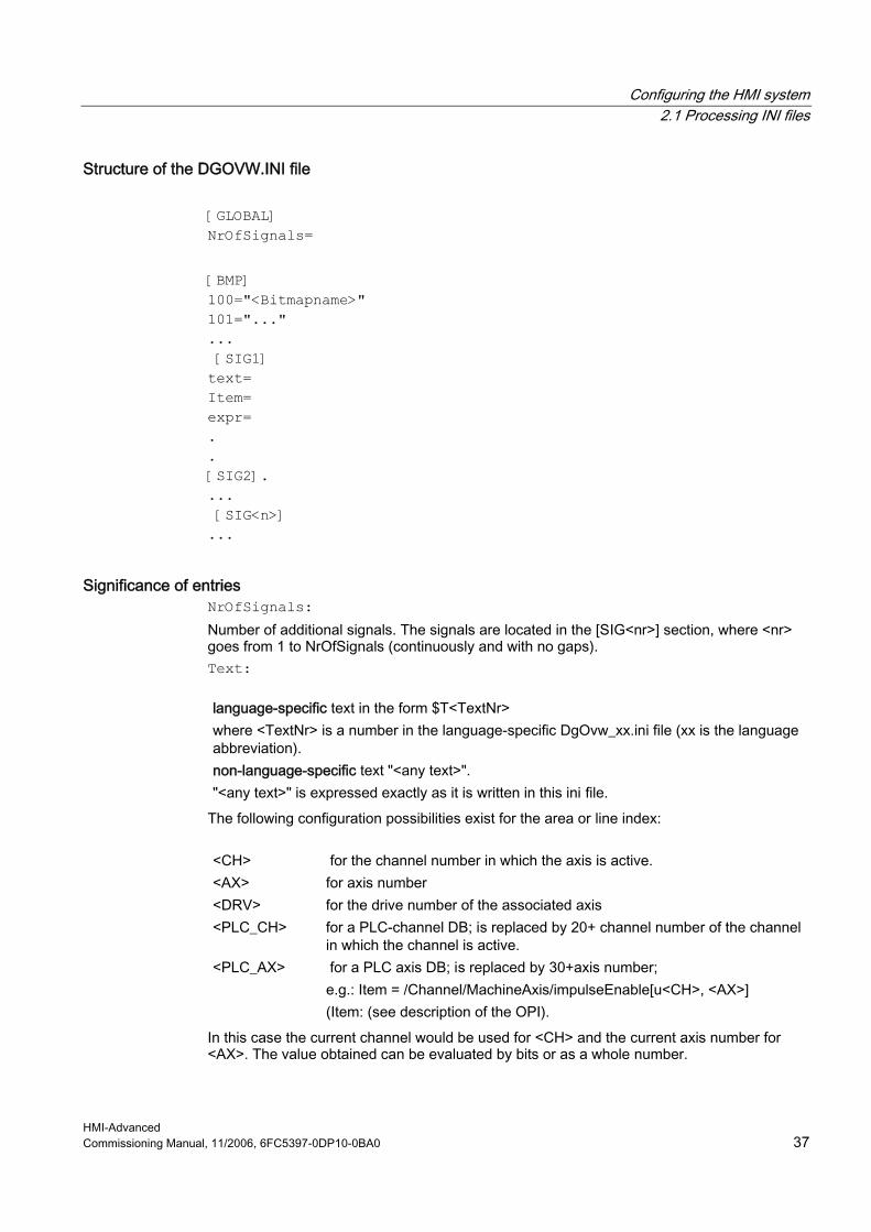
Structure of the DGOVW.INI file [GLOBAL] NrOfSignals= [BMP] 100="<Bitmapname>" 101="..." ... [SIG1] text= Item= expr= . . [SIG2]. ... [SIG<n>] ...
Significance of entries NrOfSignals: Number of additional signals. The signals are located in the [SIG<nr>] section, where <nr> goes from 1 to NrOfSignals (continuously and with no gaps). Text:
language-specific text in the form $T<TextNr> where <TextNr> is a number in the language-specific DgOvw_xx.ini file (xx is the language abbreviation). non-language-specific text "<any text>". "<any text>" is expressed exactly as it is written in this ini file.
The following configuration possibilities exist for the area or line index:
<CH> for the channel number in which the axis is active. <AX> for axis number <DRV> for the drive number of the associated axis <PLC_CH> for a PLC-channel DB; is replaced by 20+ channel number of the channel
in which the channel is active. <PLC_AX> for a PLC axis DB; is replaced by 30+axis number;
e.g.: Item = /Channel/MachineAxis/impulseEnable[u<CH>, <AX>] (Item: (see description of the OPI).
In this case the current channel would be used for <CH> and the current axis number for <AX>. The value obtained can be evaluated by bits or as a whole number.
Configuring the HMI system 2.1 Processing INI files
HMI-Advanced 38 Commissioning Manual, 11/2006, 6FC5397-0DP10-0BA0
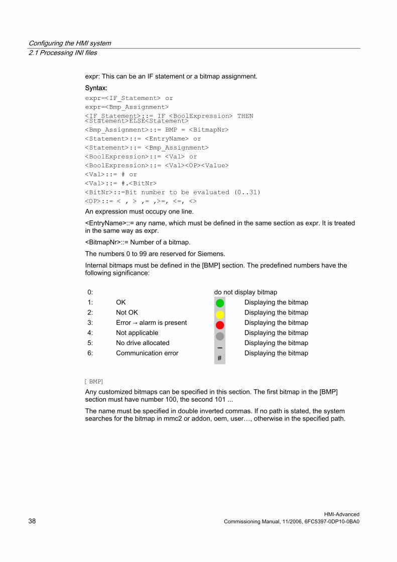
expr: This can be an IF statement or a bitmap assignment. Syntax: expr=<IF_Statement> or expr=<Bmp_Assignment> <IF_Statement>::= IF <BoolExpression> THEN <Statement>ELSE<Statement> <Bmp_Assignment>::= BMP = <BitmapNr> <Statement>::= <EntryName> or <Statement>::= <Bmp_Assignment> <BoolExpression>::= <Val> or <BoolExpression>::= <Val><OP><Value> <Val>::= # or <Val>::= #.<BitNr> <BitNr>::=Bit number to be evaluated (0..31) <OP>::= < , > ,= ,>=, <=, <> An expression must occupy one line. <EntryName>::= any name, which must be defined in the same section as expr. It is treated in the same way as expr. <BitmapNr>::= Number of a bitmap. The numbers 0 to 99 are reserved for Siemens. Internal bitmaps must be defined in the [BMP] section. The predefined numbers have the following significance:
0: do not display bitmap 1: OK Displaying the bitmap 2: Not OK Displaying the bitmap 3: Error → alarm is present Displaying the bitmap 4: Not applicable Displaying the bitmap 5: No drive allocated Displaying the bitmap 6: Communication error
Displaying the bitmap
[BMP] Any customized bitmaps can be specified in this section. The first bitmap in the [BMP] section must have number 100, the second 101 ... The name must be specified in double inverted commas. If no path is stated, the system searches for the bitmap in mmc2 or addon, oem, user…, otherwise in the specified path.

Configuring the HMI system 2.1 Processing INI files
HMI-Advanced Commissioning Manual, 11/2006, 6FC5397-0DP10-0BA0 39
Example: Signal for measuring system 1 active [GLOBAL] NrOfSignals=1 [BMP] 100="test.bmp" 101="c:\tmp\test2.bmp" [SIG1] text= "Measuring system 1 active" Item= /Nck/MachineAxis/encChoice[u1, <AX>] expr= if #=1 then BMP=100 else expr2 expr2= if #=0 then BMP=101 else BMP=2
Structure of the DGOVWTXT_XX.INI File xx in the file name stands for the language abbreviation for the language-specific file. The only section is the [TEXT] section. The individual tests are listed here in the form: $T<Text No.>= "<any text>" listed. Values from 1000 to 32767 are permitted for <Text-Nr> and may only occur once. Values below 1000 are reserved for Siemens. This file has to exist for all languages that are required (language abbreviation as in MMC.INI).
See also DGOVW.INI (Page 150)

Configuring the HMI system 2.1 Processing INI files
HMI-Advanced 40 Commissioning Manual, 11/2006, 6FC5397-0DP10-0BA0
2.1.10 Creating technology-specific texts
Function The following sections are available in the IF.INI file for parameterizing the Help functions: • TECHNOLOGY • TEXTFILES • CONTEXT • TEXTSEARCH
Section [TECHNOLOGY] The technology group to which the machine belongs can be specified in the [TECHNOLOGY] section in order to limit the display of instruction texts to those entries that are relevant for the machine. Then, only entries that are relevant to the technology group are displayed. The following technology codes can be specified: "m" = Milling "t" = Turning "g" = Grinding "s" = Nibbling "p" = Punching "a" = Display all technologies
Section [TEXTFILES] The paths (path\name) of the Quick Help text files on which the help function is based are parameterized in the [TEXTFILES] section. The help function accesses the following text files: • Siemens dh\cst.dir\ifs_gr.com • Machine manufacturer dh\cst.dir\ifm_gr.com (any file name) • End user dh\cst.dir\user_gr.com (any file name; is also entered under "Settings")
Note The path for the Siemens text file "Dh\Cst.dir\Ifs_gr.com" must exist; if not, an error message is output accordingly.
The entry for Siemens is specified in conjunction with ISO language as: SiemensI=file where file equals ifit_xx.com for turning or where file equals ifim_xx.com for milling.
Configuring the HMI system 2.1 Processing INI files
HMI-Advanced Commissioning Manual, 11/2006, 6FC5397-0DP10-0BA0 41
There are different parameterization options for the names of the text files when assigning the text path. The following table lists the parameterization options and their interpretation by the Help function:
Parameters for the text file Interpretation FileName.com The text file that is independent of the language is read-out File name_XX.com The language-dependent text file is read out FileName_.com In this setting the non-language-specific test file is read first,
if present, otherwise the language-specific text is read.
(XX = abbreviation for languages, e.g. "GR" for German) Example: Enduser=Cus.dir\Ifm_.com First of all, the non-language-specific text file "Ifm.com" is opened in the path "C:\Dh\Cus.dir\" by default or, if the non-language-specific text file does not exist, the relevant language-specific text file (e.g. "lfm_gr.com") is opened. Extract from Short Help txt file "Ifm_gr.com": ... a2//G00/Linear interpolation with rapid traverse (m) a2//G01/Linear interpolation with feed (m) a2//G02/Circular interpolation in the clockwise direction (m) ...
Section [CONTEXT] An increased context sensitivity of the Help function can be selected in the [CONTEXT] section. This setting is activated with "1" and deactivated with "0" (is also entered under "Settings"). If the increased context sensitivity is activated and the cursor is positioned to the left of, next to or on an instruction text, then all instructions with the same initial letters are displayed when Help is called. For example, if the programmer has selected instruction "G1", then all instructions beginning with "G1" (e.g. "G1", "G17", "G18", "G19") are displayed. If increased context sensitivity has been deactivated with "0", then only the instruction actually selected (if available) is displayed.
Section [TEXTSEARCH] The text search type can be specified in the [TEXTSEARCH] section. The following search methods can be parameterized: 1 = instruction texts only 2 = descriptive texts only 3 = instruction and descriptive texts (are also entered via "Search").
See also IF.INI (Page 158)
Configuring the HMI system 2.1 Processing INI files
HMI-Advanced 42 Commissioning Manual, 11/2006, 6FC5397-0DP10-0BA0
2.1.11 Set-up workpieces with job lists
Requirements The option "multiple channel sequential programming" and a multiple channel machine with 20 channels are prerequisites. An offline mode is possible; the channels cannot be checked in this case.
Function The templates for work pieces offer a simple possibility of creating new program sequences in the form of workpieces with job lists. These templates can be adapted for an existing workpiece. In the program operating area, a workpiece is processed using "Edit workpiece." If no joblist, part program or DAT file with the workpiece name exists, an error message appears stating that the workpiece cannot be opened. If an automatic adaptation of the workpieces is activated by an entry in the MMC.INI file, an attempt is made to finish the workpiece instead of an error message.
Parameterizing The following parameters must be specified in the [Program] section in the MMC.INI file: [Program] ; 1=finished workpiece via workpiece template, ; if cannot be opened with MCSP (default) ; 0=outputs an error message: ; UpdateWorkpiecesBasedOnTemplates=1 There is only one workpiece template under templates with JOB/DAT file. The contents of this template are then automatically copied into the selected workpiece. Files that already exist in the current workpiece are not overwritten. If a JOB/DAT file with the workpiece name exists after this, the sequence editor is opened, otherwise an error message appears. If there are several workpiece templates under templates with JOB/DAT files, a "Finish workpiece" dialog appears which allows the desired workpiece template to be selected. If a part program that does not contain an INIT instruction is selected when "Edit workpiece" is activated, the "Finish workpiece" dialog is called up, which allows a selection to be made from the JOB/DAT files (if available) under templates. If a JOB/DAT file is selected, it is copied into the workpiece under the part program name and opened with this file of the sequence editor. Workpiece templates are not offered at this point, but only when a workpiece is selected. The files and messages stating that the template files are already contained in the workpiece are displayed in the log window.
Configuring the HMI system 2.1 Processing INI files
HMI-Advanced Commissioning Manual, 11/2006, 6FC5397-0DP10-0BA0 43
Error messages Error messages are displayed in the following cases: If a part program that does not contain a valid INIT instruction is selected: No INIT instruction found in the part program! There is a reference to a non-existent file in the JOB/DAT file: The following non-existent programs are addressed: There is a reference to a non-existent channel number in the JOB/DAT file: Non-existing programs are assigned to the following channels: If no entry could be created in the DAT file: No channel assignment found! Additional configuring possibilities for multi-channel step sequence programming:
See also MMC.INI (Page 169) SEDITOR.INI (Page 180)
2.1.12 Using double channel displays
Function In order to be able to use the double-channel display in the "Machine" operating area, the following sections are required in the file NETNAMES.INI: [MULTI_CHAN_i] CHAN_2 = k " i " denotes the channel number in the current NCU. The 2nd channel displayed is specified in the CHAN_2 entry CHAN_2 = k
Note When the channel menu is selected, all entries under [MULTI_CHAN_i] are ignored.
This default setting of the configuration only applies when switching from 1-channel to 2-channel display. If 2-channel display is active and a channel is switched within the display, the other channel remains unaffected.
Configuring the HMI system 2.1 Processing INI files
HMI-Advanced 44 Commissioning Manual, 11/2006, 6FC5397-0DP10-0BA0
Example for configuring a 2-channel display: There is an NCU with 6 channels. (1, 2, 3, 6, 7, 8). The channel combinations 1-6, 2-7, and 3-8 are always to be displayed together: [MULTI_CHAN_1] CHAN_2 = 6 [MULTI_CHAN_2] CHAN_2 = 7 [MULTI_CHAN_3] CHAN_2 = 8 [MULTI_CHAN_6] CHAN_2 = 1 [MULTI_CHAN_7] CHAN_2 = 2 [MULTI_CHAN_8] CHAN_2 = 3 Note: Each of the channels involved in the 2-channel display appear once in [MULTI_CHAN_i] and once as 2nd channel in CHAN_2=i.
2.1.13 Tool management (WZV)
Function The tool management HMI-Advanced already contains this functionality. The structure of the NCDDE variables of tool management follows the pattern: "TMHMICurData_"<MMCName>"_"<DataName> with TMHMI = Tool Management Human Machine Interface The following current data (<DataName>) are present: General TOA and channel data: - curTOANo current TOA number - curChannelNo current channel number Current tool in list views (tool in which the cursor lies) and in tool data images for individual tools: - curToolTNo T number - curToolIdent tool identification - curToolDuplo tool duplo number

Configuring the HMI system 2.1 Processing INI files
HMI-Advanced Commissioning Manual, 11/2006, 6FC5397-0DP10-0BA0 45
- curToolType tool type - curEdgeNo tool edge number, relative to tool and not to duplo number! - curDLNo tool edge correction location number, relative to edge - curMagNo magazine number; "0" if the current tool is not situated on a place or is intended for it. - curPlaceNo magazine place number; "0" if the current tool is not situated on a place or is intended for it. Current magazine in magazine list view: - curMagLiMagNo magazine number, Target magazine, target magazine place during loading, unloading, reloading, positioning, empty place search: - targetMagNo magazine number - targetPlaceNo magazine place number Source magazine, source magazine place during loading, unloading, reloading, positioning, empty place search: - sourceMagNo magazine number - sourcePlaceNo magazine place number Current tool in tool cabinet: - curCabToolIdent tool identification - curCabToolDuplo tool duplo number - curCabToolType tool type Current tool in tool catalog: - curCatToolIdent tool identification - curCatToolDuplo tool duplo number - curCatToolType tool type Additional information needed for commissioning can be found in: References: Function Manual Tool Management
2.1.14 Tool selection without tool management
Function The "Parameters without tool management" application provides local NCDDE variables that write to the currently selected tool. The tool management functions are used for this purpose for tool selection under Parameters. The reason why these variables are written is influenced by the settings in PARAM.INI: Variables are written to only when images change as a result of "Expand user interface" or, alternatively, at each parameter status change. The tool is selected with the cursor in the tool images without tool management. When the cursor is positioned on a tool, the internal T number and the edge number are written to local NCDDE variables for this tool. These variables can be evaluated from "Expand user interface."
Configuring the HMI system 2.1 Processing INI files
HMI-Advanced 46 Commissioning Manual, 11/2006, 6FC5397-0DP10-0BA0
All data in one variable The name of the NCDDE variables follows the pattern: "PAHMICurData"_< MMCName>, with MMCName from MMC.INI. Thus, the difference between the name of the NCDDE variables and the tool management variables lies in the prefix.
Note The NcddeMmcName and NcddeMmcName entries in the [GLOBAL] section must not have standard value "__xxxx__". Otherwise, it will be replaced by a random number.
In this variable, the current PAHMI data are fed as a string, possible in the form: "curToolTNo=35;curToolDNo=5;" with "=" as a separator between data name and data value and "," as a separator between data
Individual variables In addition (or alternatively), a separate NCDDE variable is available for data element. The name of this variable is formed from the following: "PAHMICurData_"<MMCName>"_"<DataName> where <MMCName> is taken from the mmc.ini file in the [GLOBAL] section in the NcddeMmcName entry.
Note The NCDDE server does not permit multiple variable access to NCDDE variables so that read and write accesses occur individually.
The following current data (<DataName>) for TOA and channel are present: - curTOANo Current TOA number - curChannelNo Current channel number Current tool in list views (tool in which the cursor lies) and in tool data images for individual tools: - curToolTNo T number - curToolType Tool type - curEdgeNo Tool edge number, relative to the tool, not DNo! Currently unknown values exist as "varname=;"” in the NCDDE variables or are omitted. The data sequence is not defined. As long as a data value is not set, its NCDDE variable is blank or is not present.
Configuring the HMI system 2.1 Processing INI files
HMI-Advanced Commissioning Manual, 11/2006, 6FC5397-0DP10-0BA0 47
Control of interface The interface activity can be controlled using PARAM.INI. [General] ; Options of "write current data of tool management human ; interface to ncdde variables when switch to : WIZARD forms or WIZARD softkeys occur": ; All Options have to be set by using named arguments in ; one single line. ; Options are ; switched "ON" by value "True" and ; switched "OFF" by value "False" or if named argument ; does not exist in line. ; "EnableAllTogetherWriteToNcdde := True": ; all data in one ncdde variable ; "EnableSingleWriteToNcdde := True": ; one ncdde variable per data ; Both options can be active. ; If both options are not active, ; no write to ncdde variables will occur. ; "WriteChangesWhenStateChanged := True": ; write changes when a softkey is pressed, ; even if there is no switch to WIZARD The following setting must be in a single line of PARAM.INI: HMICurDataInterface = EnableAllTogetherWriteToNcdde := True, EnableSingleWriteToNcdde := True, WriteChangesWhenStateChanged := False
2.1.15 Executing from the hard disk (m:n configuration)
Requirements Included in the NETNAMES.INI file are descriptions of the following: • Configuration of assignments of multiple HMI components and multiple NCU components
(m:n configuration). If, for example, multiple HMI components have been assigned to one NCU, the unit that is to provide the part program in the event of "Execution from external source (hard disk)" must be specified.
• Configuration of channel menu for multiple channel systems (for powerline) • Reference to file with symbols for PLC signals
Function EXTCALL In order to execute external programs that are located on the hard disk of the PCU in the data management system from the part program using the EXTCALL program command,
Configuring the HMI system 2.1 Processing INI files
HMI-Advanced 48 Commissioning Manual, 11/2006, 6FC5397-0DP10-0BA0
the following entries, for example, are required in the section [conn HMI_x] of the NETNAMES.INI file. ; HMI identification part [own] owner= HMI_3 ; Description of possible connections ; Connection part [conn HMI_3] conn_1= NCU_1 conn_2= NCU_2 conn_3= NCU_3 conn_4= NCU_4 EXTCALL_conns=conn_1, conn_2, conn_3, conn_4 ; conn_i identifier for the NCUs that can access the PCU (with HMI) (refer to the note) ; Description of significant net parameters [param network] bus= opi ; HMI descriptions [param HMI_3] HMI_typ = 0x40 HMI_...... ; descriptive part, NCU components [param NCU_1] type =NCU_573 nck_address= 11 plc_address= 11 name = NCU1 ... ; Reference to the file with symbols for PLC signals from NCU_1 PlcSymbolFile=PlcSym
Note The entry EXTCALL_Conns … is only needed in the "main operating field" in the NETNAMES.INI file, not in the "secondary operating fields".
References: Function Manual, Expansion Functions: Several operator panel fronts on several NCUs, distributed systems (B3)
See also NETNAMES.INI (Page 174)
Configuring the HMI system 2.2 Connecting network drives
HMI-Advanced Commissioning Manual, 11/2006, 6FC5397-0DP10-0BA0 49
2.2 Connecting network drives
2.2.1 Setting up access to external drives or computers
Use The control can be connected to external network drives or other computers. This makes it possible, for example, to execute part programs from other computers. Two alternatives are available: • A maximum of 4 drives can be connected by parameterizing display machine data. • A maximum of 8 drives can be connected by configuring the LOGDRIVE.INI file. The two options cannot be applied jointly. The LOGDRIVE.INI file is the preferred choice for applications with multiple TCUs or PCUs because it allows global network access to these drives. The user-specific entries of this file are stored in the directory.
See also LOGDRIVE.INI (Page 159)
2.2.2 Connecting Drives with Display Machine Data
Configuring drives/computers A maximum of four network drives can be set-up with the following display machine data: MD 9676 CMM_DIRECTORY_SOFTKEY_PATH1="path1" MD 9677 CMM_DIRECTORY_SOFTKEY_PATH2="path2" MD 9678 CMM_DIRECTORY_SOFTKEY_PATH3="path3" MD 9679 CMM_DIRECTORY_SOFTKEY_PATH4="path4" The complete path must be entered. The paths are displayed on the softkeys. The connections can be specified as DOS path e.g. "E:" or "G:\VORBEREI\MPF_DAT" or as network addresses consisting of node identifiers, share name and directory, e.g. "\\R111\<Sharename>\MPF_DAT". Example: MD9677 CMM_DIRECTORY_SOFTKEY_PATH2=F:\R4711 ;drive + directory MD9678 CMM_DIRECTORY_SOFTKEY_PATH3=\\R4712\TEIL1\WELLE1.DIR ; computer name, enable name with directory data MD9679 CMM_DIRECTORY_SOFTKEY_PATH4=\\R4713\Part2\MPF_DAT .DIR ; Computer name, enable name with directory data

Configuring the HMI system 2.2 Connecting network drives
HMI-Advanced 50 Commissioning Manual, 11/2006, 6FC5397-0DP10-0BA0
The network connection to be specified in MD 9676 CMM_DIRECTORY_SOFTKEY_PATH1 is reserved for SINUMERIK ShopMill or ShopTurn.
Configuring texts for softkeys Plain text identifiers for selecting network drive connections with softkeys can be stored as language-dependent user alarm texts under numbers 89901 to 89905 in a user text file that is known to the message block (see MBDDE.INI, [TextFiles] section). Text number 89901 correlates here to MD 9676 CMM_DIRECTORY_SOFTKEY_PATH1, etc. Example: MBDDE.INI: ... [TextFiles] USER_PLC=F:\DH\MB.DIR\MYTXT_ MYTXT_GR.COM:
89901 0 0 "" Reserved 89902 0 0 "F:\R4711" Softkey text for softkey 2 89903 0 0 "R4712/ MMC1" Softkey text for softkey 3 89904 0 0 "R4713/ MMC2" Softkey text for softkey 4 ... (2 blanks denote a line break)
Availability in the operating areas The network drives are available in the following operating areas: • In the MACHINE operating area on the expanded SK (softkey) bar behind the "Program
overview" softkey • In the PROGRAM operating area as an extended softkey bar in the main menu • In the SERVICES operating area under "Manage data" (if 3 network drives are
configured, 3 are displayed directly as horizontal softkeys, the fourth appears after pressing the ETC button)
• In the SERVICES operating area under "Data on" and "Data off" under the second vertical softkey "Network drives …"
The softkeys in the expanded softkey bar are assigned accordingly to MD 9676 (SK1) to 9679 (SK4) (i.e., with gaps if necessary). The configured text appears on the softkey. If no labeling text is configured for the softkey, the value of the corresponding machine data is displayed.

Configuring the HMI system 2.2 Connecting network drives
HMI-Advanced Commissioning Manual, 11/2006, 6FC5397-0DP10-0BA0 51
Assigning access authorization for drives/computers Access authorizations are configured individually for each drive in the following display machine data: For the Program and Services: $MM_USER_CLASS_DIRECTORY1_P (9510) $MM_USER_CLASS_DIRECTORY2_P (9511) $MM_USER_CLASS_DIRECTORY3_P (9512) $MM_USER_CLASS_DIRECTORY4_P (9513) For the Machine area: $MM_USER_CLASS_DIRECTORY1_M (9516) $MM_USER_CLASS_DIRECTORY2_M (9517) $MM_USER_CLASS_DIRECTORY3_M (9518) $MM_USER_CLASS_DIRECTORY4_M (9519) The display machine data for access authorizations are activated immediately, i.e., after switchover to the respective application, while a change in directories takes effect only after a restart.
Error messages The configured network drives are evaluated when HMI-Advanced boots. This evaluation does not check whether the connection actually exists. This check is made after the drive is selected by the operator. If the configured path cannot be accessed, an error message is issued.
See also MBDDE.INI (Page 165)
2.2.3 Connecting logical drives
Requirements The "logical drives" softkey is available from access level 2 onwards (Service): This is the reason that a machine operator cannot use this function, but instead only a service technician. A restart of HMI-Advanced is necessary to update the assignment of the softkeys. With this softkey you can configure access to USB storage media on USB interfaces or PCU and TCU and to network drives (option) in the Programs, Services, or Diagnostics operating areas.

Configuring the HMI system 2.2 Connecting network drives
HMI-Advanced 52 Commissioning Manual, 11/2006, 6FC5397-0DP10-0BA0
Function The control can be connected to external network drives or other computers. This makes it possible, for example, to execute part programs from other computers. Two alternatives are available: • In the setting screen "Logic drives" under "Start-up" → "NC". • By configuring file LOGDRIVE.INI. Configuring a logical drive comprises the following tasks: • Path name with the following structure:
"acttcu://<TCU connector>,<Partition>/<Path name>" For the USB at a TCU name entry, connection field identifying the required connector, and a partition number
• and a softkey label (either a language-neutral or language-dependent softkey label by means of alarm texts).
Softkey "USB local" As supplied: Connection 1 is pre-assigned as "USB local". The “"USB local" softkey is always displayed in the Machine, Program, and Services operating areas, even if it is not configured. This enables the front interface of the active TCU or the configured interface of the PCU to be displayed.
Note If an OEM softkey (horizontal softkey 7) is configured, a maximum of 7 network drives are displayed in the program. The last entry is ignored.

Configuring the HMI system 2.2 Connecting network drives
HMI-Advanced Commissioning Manual, 11/2006, 6FC5397-0DP10-0BA0 53
Figure 2-2 "Logical Drives" setting screen
Connection type / connection The following connections can be selected.
No drive: No additional fields are displayed: Local USB: Designation of the local USB interface:
- Front (0.2 or 1:0.2 or FRONT) - X203 (1 or 1:1 or X203) - X204 (2 or 1:2 or X204)
Partition: (for local and global USB)
e.g. 2
Global USB: Designation of the global USB interface: - Front (0.2 or 1:0.2 or FRONT) - X203 (1 or 1:1 or X203) - X204 (2 or 1:2 or X204)
Device: (only for global USB) e.g. tcu NW Windows: Designation of the network drive (under Windows).
The path must begin with // or \\. User name: (only for NW Windows)
The user name can be entered in the user interface, e.g. Mustermann.
Password: (only for NW Windows)
The password is displayed on the user interface with a *. It is encoded and entered in the logdrive.ini file.
Local drive: Drive letter, e.g. D:
Configuring the HMI system 2.2 Connecting network drives
HMI-Advanced 54 Commissioning Manual, 11/2006, 6FC5397-0DP10-0BA0
Access authorizations The access authorizations to the connections can be assigned from level 0 to 7. If no entry is made, the default setting is applied (7 = Access for all). Only one access level can be specified for all the operating areas: • Machine • Program • Services
Softkey labels Two lines with a maximum of 10 characters are available for the labeling text of a softkey. \n,%n or two blanks can be used to separate lines. For labeling the softkeys, the alarm texts 89901- 89906 are evaluated in order to store language-dependent softkey texts if no other labeling is defined.
Data transfer to and from the TCU The USB interface of the TCU that is currently active is always the one accessed, i.e. has the operator focus. If the active TCU changes during a data transfer, the data transfer remains active in the background. If an operation (copy, delete, edit) is active on the drive at the time of the TCU switchover, the display is retained until the action is finished. The display is not updated until the operation is finished.
Note Because the TCU is connected to the PCU via a network connection, the response times depend on the particular network. Executing a part program (EXTCALL) from USB memory is not recommended. If a USB drive is disconnected while data are being written to or read from this drive, data loss can result.
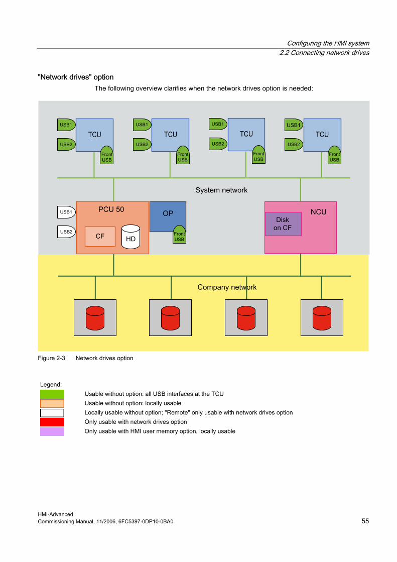
Configuring the HMI system 2.2 Connecting network drives
HMI-Advanced Commissioning Manual, 11/2006, 6FC5397-0DP10-0BA0 55
"Network drives" option The following overview clarifies when the network drives option is needed:
Figure 2-3 Network drives option
Legend:
Usable without option: all USB interfaces at the TCU Usable without option: locally usable Locally usable without option; "Remote" only usable with network drives option Only usable with network drives option Only usable with HMI user memory option, locally usable

Configuring the HMI system 2.3 Optimizing simulation
HMI-Advanced 56 Commissioning Manual, 11/2006, 6FC5397-0DP10-0BA0
2.3 Optimizing simulation
Overview This function can be used to simulate machining on the screen. Data evaluated by the simulation has to be copied into data management in the Dialog programming\Simulation data directory (\DP.DIR\SIM.DIR). When the simulation program is started the following functions can be selected with the "Data matching" softkey: • Match setup data • Match tools • Match machine data • Match cycles
2.3.1 Display of the simulation files
User programs The files loaded into the simulation are displayed with softkey Match data → Loaded data All programs currently copied into the simulation are displayed. They are deleted from the simulation again when a different workpiece is selected. Changes to these programs via the compensation editor are made directly in the HMI or NCK, and the modified programs are automatically copied into the simulation. If these programs are modified externally (e.g. via Services), the change is detected at the time of the next simulation selection and the programs concerned are copied into the simulation. If files exist for the current workpiece (extension RPA, GUD, SEA, UFR, PRO, CEC, TOA, TMA), they are loaded into the simulation when the workpiece is selected. These files are retained when the workpiece is changed and their date stamp is monitored. If these files are modified externally (e.g. via Services / Programs), the change is detected at the time of the next simulation selection and the files concerned are automatically loaded into the passive file system for the simulation. • Basic data
The initialization data (INITIAL.INI), tool data (TO_INI.INI) and definition files (*.DEF) loaded into the simulation are displayed. The files (CH(c)_xxx.INI, NC_xxx.INI and AX_SEA.INI) are displayed under "Loaded data". The date stamp for these files is evaluated. If these files are modified externally (e.g. via Services), the change is detected at the time of the next simulation selection and the files concerned are automatically loaded into the simulation.
• Standard cycles All standard cycles loaded into the simulation are displayed: The cycles are then copied into the simulation when required. Changes to the cycles are not detected automatically and must be detected by means of the "Match cycles" softkey.

Configuring the HMI system 2.3 Optimizing simulation
HMI-Advanced Commissioning Manual, 11/2006, 6FC5397-0DP10-0BA0 57
• User cycles All user cycles loaded into the simulation are displayed: If the cycles have not been loaded before, the cycle interfaces must be defined in the file DPCUSCYC.COM. The cycles are then copied into the simulation when required. Changes to the cycles are not detected automatically and must be detected by means of the "Match cycles" softkey.
• Manufacturer cycles All manufacturer cycles loaded into the simulation are displayed: If the cycles have not been loaded before, the cycle interfaces must be defined in the file DPCUSCYC.COM. The cycles are then copied into the simulation when required. Changes to the cycles are not detected automatically and must be detected by means of the "Match cycles" softkey.
2.3.2 Data match of the simulation
Overview The data to be evaluated by the simulation must be located in the data management system in \DP.DIR\SIM.DIR. They are downloaded each time simulation is started. Data are not activated until the simulation is restarted! In addition, definition files in the data management directory are matched with the NC. If you do not wish the definition files in the data management directory to be matched with the NC, you can set this in DPSIM.INI. [MAIN] MATCH_NCU_ENVIRONMENT=0 ;only the INITIAL.INI is copied from the NC. MATCH_NCU_ENVIRONMENT=1 ;(default)
Note The data can be adjusted manually using the editor in the "Services" operating area, but if improper changes are made there is a risk that the simulation will not be able to start. You should therefore save the files systematically in case the data should not/cannot be retrieved from the NC.
The following functions are listed under the softkey "Data matching":
Match setup data The following data are listed from which a selection can be made as to which data is downloaded from the active file system of the NC into the simulation: • R parameters (RPA) • User data (GUD) • Global user data

Configuring the HMI system 2.3 Optimizing simulation
HMI-Advanced 58 Commissioning Manual, 11/2006, 6FC5397-0DP10-0BA0
• Work offsets (UFR) • Global work offsets • Setting data (SEA) • Global setting data • Axis-specific setting data • Protection zones (PRO) • Sag/angularity (CEC) The data can be selected in any combination. The channels are selected using softkeys (if there is more than one channel for simulation); the current channel of the simulation is offered as default. Channel-specific data are only offered if the selected channel is present on the NCK. The selected data are copied into corresponding files in the data management system under \DP.DIR\SIM.DIR using the "OK" softkey and loaded into the simulation. Existing files are overwritten without prompting. If data are selected for all channels, any associated channel-specific files that are present are deleted; channel-specific files are always created or overwritten. Before the data are loaded into the simulation, a "channel reset" is performed for the simulation. If an error occurs when copying from the NCK, the transfer can be repeated or aborted (dialog box: Abort/Repeat). If an error occurs when loading into the simulation or a simulation alarm is triggered, the transfer is aborted. Pressing the "OK" softkey saves the current data selection and displays it again the next time the dialog box is opened.
Match tools The NC tool data for all channels are copied into the TO_INI.INI file and then activated in the simulation. Existing tools are removed beforehand. The function is offered automatically whenever simulation is selected if tool data in the NC have changed.
Match machine data All definition files (UMAC.DEF, SMAC.DEF, MMAC.DEF, UGUD.DEF, SGUD.DEF, MGUD.DEF, GUD4.DEF – GUD9.DEF) that are active in the NC are copied to the corresponding files in the HMI. Files that are not active in the NCK are deleted from the HMI. All files (CH(c)_xxx.INI, AX_SEA.INI, NC_xxx.INI) are deleted with the exception of the tool data. The machine data from the INITIAL.INI file are interpreted by the simulation. We recommend to set the following machine data: MD 11210: UPLOAD_MD_CHANGES_ONLY = 0
Match cycles Cycle changes are not monitored by the simulation. They are either copied automatically into the simulation as required (PRELOAD/CYCLES=0) or copied in their entirety into the simulation when the simulation boots.

Configuring the HMI system 2.3 Optimizing simulation
HMI-Advanced Commissioning Manual, 11/2006, 6FC5397-0DP10-0BA0 59
If a cycle is changed, it must be copied into the simulation using the "Match cycles" softkey. Only cycles that have changed since they were last accessed are copied into the simulation (along with newly imported cycles). Cycles in the simulation that have since been deleted are deleted from the simulation. If an automatic cycle interface is not used, the simulation must be restarted.
Mirroring tools Differently oriented tool carriers (e.g. in different NC channels) can be used in the same machine tool, for which the TOA length compensation parameters are subject to machine tool-specific frame transformations (e.g. MIRROR) and have to be specified differently from the usual settings. In order to be able to support this constellation when orientating the graphic tool, the SIM graphic module DPSMASCH.DLL among others, is expanded, in the turning version, by an essentially universal evaluation of the TOA parameter. e.g. $TC_DP3[n,m]=... can also be evaluated with negative values with the convention so that as standard positive length dimensions generally result in a machining "behind the center of rotation" and negative length dimension results in machining "in front of the center of rotation". Special NC instructions may also be needed in the corresponding user cycles for tool carrier selection to ensure that the simulation proceeds with the correct orientation of the graphics tools, e.g. ... IF $P_SIM $SC_MIRROR_TOOL_LENGTH=1 ; tool length compensation mirror mirrored axes for SIM ENDIF ... Operator control (milling and turning): The sign-compliant evaluation of the TOA parameters at the interface to the graphics module means that no operator action is required.
Rotating the coordinate system The orientation of the coordinate system for simulation views (until now largely incomplete in the turning version) can be altered and adjusted, for example, to rotary machines. For this purpose, the INI entry [VIS] PLANE_VIEW=.. (in ..\user\dpmwp.ini for the milling version or dptwp.ini for the turning version) can be modified. In order for advantage to be taken of these possibilities in machines that differ from the standard orientations, the value range of the entry is published (B/F: back/front, U/D: up/down, L/R: left/right) and the functionality during turning expanded accordingly (incl. the derived views: Outside cut, half cut and full cut, surface area) (wire model is kept as before!). In some cases (lathes) the entries can be directly accessed at the user interface: a[VIS] … ;Plane viewpoint default for standard milling: BDL(BackDownLeft) ;possible BDL, BUL, BUR, BDR, FDL, FUL, FUR or FDR PLANE_VIEW=BDL

Configuring the HMI system 2.3 Optimizing simulation
HMI-Advanced 60 Commissioning Manual, 11/2006, 6FC5397-0DP10-0BA0
or [VIS] … ;Plane viewpoint default for standard horizontal lathes: BDR(BackDownRight) ;for vertical lathes with +Z upward: BDL or with +Z downward: FUL (*** from SW5.3 ***) ;possible BDL, BUL, BUR, BDR, FDL, FUL, FUR or FDR PLANE_VIEW=BDR
Note Entries other than BDR, BDL or FUL are of no use for lathes at present.
Operator control (only turning): To support vertical lathe orientations, the existing "Set spindle" form has been expanded to include an additional "Machine orientation" frame group, initially with 3 option controls: "horizontal standard" (default: PLANE_VIEW=BDR), "vertical, downward feed" (PLANE_VIEW=BDL)and "vertical, upward feed" (PLANE_VIEW=FUL). Using the "Change default" softkey the adjustments made here can also be used as a permanent reference for all new workpieces.
Optimizations • Input monitoring "Unwind diameter peripheral surface"
In the turning version, in conjunction with the blank inputs, the consistency of the "External diameter" and "Unwinding diameter surface area" parameters is checked and, if necessary, adjusted automatically (e.g. if the external diameter is reduced), and missing entries are signaled (e.g. empty input field for unwind diameter).
• Tool center point path ("without tool data") Temporarily received for the subsequent selection of a tool data source (e.g. "with tools"). In order for the correct selection and deselection of tool compensations (LK, FRK, SRK) to be checked visually, it is useful to be able to visually compare the tool center-point path when tool compensations are deselected and the tool path when tool compensations are selected. For this purpose, the tool center-point path produced from a simulation run "without tool data" is therefore generally retained for the first subsequent simulation run "with tool data" (tool paths with and without tool compensations are overlaid graphically for one SIM session). Thereafter the tool paths are reset as usual at the start of each simulation.
Configuring the HMI system 2.3 Optimizing simulation
HMI-Advanced Commissioning Manual, 11/2006, 6FC5397-0DP10-0BA0 61
2.3.3 Speeding up the simulation boot
Simulation start The simulation application is normally started only on request by the operator. This means that the system is only loaded as required as a result of the software components to be downloaded. At the same time, however, this significantly increases the start time for the simulation when it is called for the first time. The start time is the time from selecting the simulation to execution of the first NC command ("visible" result).
Downloading when the HMI boots To speed-up simulation starting, the downloading times can be transferred to the HMI boot. The settings for this are carried out in the REGIE.INI file (OEM or USER directory). [StartupConfiguration] Startup12 = name:=dpncsim, Timeout:=0 [TaskConfiguration] Task27 = name := dpsim, Timeout := 30000
Note The entry used in the [StartupConfiguration] section must not have been used anywhere else. Check this in the REGIE.INI file in the MMC2, ADD_ON, OEM and USER directories.
Loading when SimNCK boots Configuration files for the NC environment (tool data, cycles) are loaded when the SimNCK is booted. This means that only the program to be executed and its subroutines need to be loaded into the simulation NCK. This behavior when booting is controlled by means of the [PRELOAD] and [MAIN] sections in the DPSIM.INI file. The starting time of the simulation can be shortened by using the following settings: [PRELOAD] CYCLES=1 All cycles (from NCK and hard disk) are preloaded when the simulation NCK is booted with DPNCSIM.EXE. TOOLS=1 The files for the tool mapper (TO_INI.INI and TO_ADDON.INI) are preloaded when the simulation NCK is booted (if applicable).

Configuring the HMI system 2.3 Optimizing simulation
HMI-Advanced 62 Commissioning Manual, 11/2006, 6FC5397-0DP10-0BA0
2.3.4 Expanding geometrical tool data
Representation of the tools Previously tools could only be shown with their cutting edge, shaft and holder, which could be calculated from the data in the NCK. With the expansion of the tool geometry data, it is now possible to show only the cutting edge ("flying edge") in the simulation image, without the shank and holder. Additional, deviating parameters can also be incorporated into the simulation on a tool-by-tool basis. The tool data are defined in the file SIMTOGEO.INI, which is stored in one of the directories \USER, \OEM, \ADD_ON, or \HMI_ADV. This file is not supplied with the system as standard. Other requirements: • Activating the "flying edge" function in DPTWP.INI or DPMWP.ini • Machine data: Defining memory for OEM parameters • Creating the SIMTOGEO.INI file, insert link in file
Parameterization In the SimToGeo.ini file in the section [Settings] there must be an entry that establishes a link to the NCK tool data. [Settings] Link=TC_DPCx with x = 1... 10 or Link=TC_DPCSx with x = 1... 10 We recommend using the parameter TC_DPCS1 as the link entry for new projects, as this has been specially reserved for this purpose. A different link setting should only be used if the parameter TC_DPCS1 is already in use in an existing project.
Example With Link=TC_DPCS1, for example, for every tool for which entries exist in SimToGeo.ini, an entry $TC_DPCS1[t, d]= <Identifier> must be specified for the NCK tool data, where t = tool number and d = duplo number. Identifier must be noted as a real number, e.g. 500.1, where the number before the decimal point can represent a tool type and the number after the decimal point allows a further distinction. The associated values in SimToGeo.ini appear below the corresponding identifier: [500.1] ; roughing tool 1 tool_type = 500 ...
Configuring the HMI system 2.3 Optimizing simulation
HMI-Advanced Commissioning Manual, 11/2006, 6FC5397-0DP10-0BA0 63
Optional parameters for orienting milling cutters Tools are still displayed in the 3 main planes, XY, YZ or ZX. If a tool cannot be displayed, a polymarker is displayed. Only one of these entries may be used: TC_DPV3= ; 1 = +X, -1 = -X TC_DPV4= ; 1 = +Y, -1 = -Y TC_DPV5= ; 1 = +Z, -1 = -Z It is not possible to enter a tool orientation that is freely located in space. In the file SimToGeo.ini, a tool can be defined under tool_type that differs from the definitions of the NC. If the corresponding cutting edge parameters (e.g. $TC_DPCS1[t,d]) can be set, a link to or evaluation of geometrical data with SimToGeo.ini is also possible. A complete sample file with entries for each permissible tool type can be found in Chapter "SIMTOGEO.INI"
Setting machine data MD 18080: MM_TOOL_MANAGEMENT_MASK='H4' ;Set aside memory for OEM data MD 18204: MM_TYPE_CCS_TOA_PARAM[0]=4 ;Data type 4 = Real MD 18206: MM_NUM_CCS_TOA_PARAM=1 ;Number of OEM data per cutting edge 0 to 10
Procedure when commissioning the system: 1. Activating the "Flying edge" function in DPTWP.INI or DPMWP.INI, depending on the
turning/milling technology: [SETUP] ;*** only SW6.4 or later *** ;Display tool only as cutting edge "flying edge" (ON/OFF) TOOL_AS_CUTTING_EDGE=ON ;default = OFF
2. Defining machine data or memory for OEM parameters: $MN_MM_TOOL_MANAGEMENT_MASK=4 ;for SimToGeo.ini, set bit 2=1 If MD is already pre-assigned, the bit must be additionally set - define memory and type for SIEMENS-OEM parameter $TC_DPCS1 $MN_MM_NUM_CCS_TOA_PARAM=1 ;TC_DPCS1 is reserved. $MN_MM_TYPE_CCS_TOA_PARAM[0]=4 ;data type float for TC_DPCS1 or Define memory and type for USER-OEM parameter $TC_DPC1 $MN_MM_NUM_CC_TOA_PARAM=1 ;TC_DPC1 is reserved $MN_MM_TYPE_CC_TOA_PARAM[0]=4 ;data type float for TC_DPC1
3. Set up SimToGeo.ini: Define link entry for Siemens or User OEM parameter and expand geometrical data. This is done using the OEM variable ($TC_DPCS1/$TC_DPC1). The values of these variables determine the geometrical block that is used.
Configuring the HMI system 2.3 Optimizing simulation
HMI-Advanced 64 Commissioning Manual, 11/2006, 6FC5397-0DP10-0BA0
For example, the entry for tool 1 cutting edge 1 (T1 D1) $TC_DPCS1[1,1]=500.1 would be referred to the geometrical data block [500.1] in the SimToGeo.ini file. It is possible for more than one tool to refer to the same geometrical data block.
4. Adding expanded geometrical tool data. This in done in blocks, which are distinguished e.g. using identifiers, float type. For example [500.1]. [Settings] Link=TC_DPCS1 ;link to TO_INI.INI, Siemens OEM ;Link=TC_DPC1 ;link to TO_INI.INI, USER OEM [500.1] ;T1 D1 roughing tool type 500 SL3 L1=100, L2=55, R1 tool_type=500 ;tool type then $TC_DP1 is not required insert_length=10 ;TC_DP8, plate length holder_angle=105 ;TC_DP10, holder angle, not rake angle reference_direction=3 ;TC_DP11, cutting edge position clearance_angle=5 ;TC_DP24, clearance angle
5. Link to tool data/TO_INI.INI: CHANDATA(1) $TC_DPCS1[1,1]=500.1 ;Siemens OEM T1 D1 Roughing tool SL3 type 500 $TC_DPC1[1,1]=500.1 ; User OEM $TC_DP1[1,1]=500 $TC_DP2[1,1]=3 $TC_DP3[1,1]=100 $TC_DP4[1,1]=55
2.3.5 Optimizing the memory requirement
Function To avoid having to carry out memory settings in NC machine data if additional memory is needed for the simulation, these settings can be carried out in the DPSIMNCK.INI file in the [DP_SIMNCK] section. The default values for the simulation are entered in the dpsimnck.ini file in the [DP_SIMNCK] section, generally eliminating the need for additional memory settings in the NC. These offset values have a cumulative effect on machine data with the same name.
Configuring the HMI system 2.3 Optimizing simulation
HMI-Advanced Commissioning Manual, 11/2006, 6FC5397-0DP10-0BA0 65
Entries in the file DPSIMNCK.INI Negative values are ignored. The following entries with default values are contained in the [DP_SIMNCK] section: ... [DP_SIMNCK] DP_SIMNCK_MM_NUM_GUD_MODULES_OFFSET = 0 with MD 18118: MM_NUM_GUD_MODULES DP_SIMNCK_MM_NUM_GUD_NAMES_NCK_OFFSET = 5 with MD 18120: MM_NUM_GUD_NAMES_NCK DP_SIMNCK_MM_NUM_GUD_NAMES_CHAN_OFFSET = 30 with MD 18130: MM_NUM_GUD_NAMES_CHAN DP_SIMNCK_MM_GUD_VALUES_MEM_OFFSET = 20 with MD 18150 MM_GUD_VALUES_MEM DP_SIMNCK_MM_NUM_USER_MACROS_OFFSET = 10 MD 18160: MM_NUM_USER_MACROS DP_SIMNCK_MM_NUM_MAX_FUNC_NAMES_OFFSET = 40 with MD 18170 MM_NUM_MAX_FUNC_NAMES DP_SIMNCK_MM_NUM_MAX_FUNC_PARAM_OFFSET = 350 with MD 18180 MM_NUM_MAX_FUNC_PARAM DP_SIMNCK_MM_MAX_SIZE_OF_LUD_VALUE_OFFSET = 400 with MD 18242: MM_MAX_SIZE_OF_LUD_VALUE ...
Configuring the HMI system 2.4 Creating user alarms
HMI-Advanced 66 Commissioning Manual, 11/2006, 6FC5397-0DP10-0BA0
2.4 Creating user alarms
2.4.1 Structure of user-specific alarms
Classification of alarms The following alarm numbers are available for the cycle alarms, compile cycle alarms, and PLC alarms:
Numerical range Designation Effect Deletion 60000 - 60999 Cycle alarms (Siemens) Display, interlocking NC start Reset 61000 - 61999 Display, interlocking NC start, no motion
after executing the pre-decoded blocks Reset
62000 - 62999 Display Cancel 63000 - 64999 Reserved 65000 - 65999 Cycle alarms (user) Display, interlocking NC start Reset 66000 - 66999 Display, interlocking NC start, no motion
after executing the pre-decoded blocks Reset
67000 - 67999 Display Cancel 68000 - 69000 Reserved 70000 - 79999 Compile-cycle alarms: 400000 - 499999 PLC alarms general 500000 - 599999 PLC alarms for channels 600000 - 699999 PLC alarms for axes and spindles 700000 - 799999 PLC alarms for users 800000 - 899999 PLC alarms for sequence
cascades/graphs
Format of text file for cycle alarm texts The structure of the text file for cycle alarms and compile cycle alarms is as follows:
Alarm number Display Help ID Text or alarm number 60100 1 0 "No D number %1 programmed" 60101 1 0 60100 ... ... ... ... 65202 0 1 "Axis %2 in channel %1 is still moving" // Alarm text file for cycles in English
The number range in the list is not available with every number. Reference: Function Manual Basic Functions: PLC basic program (P3 sl)
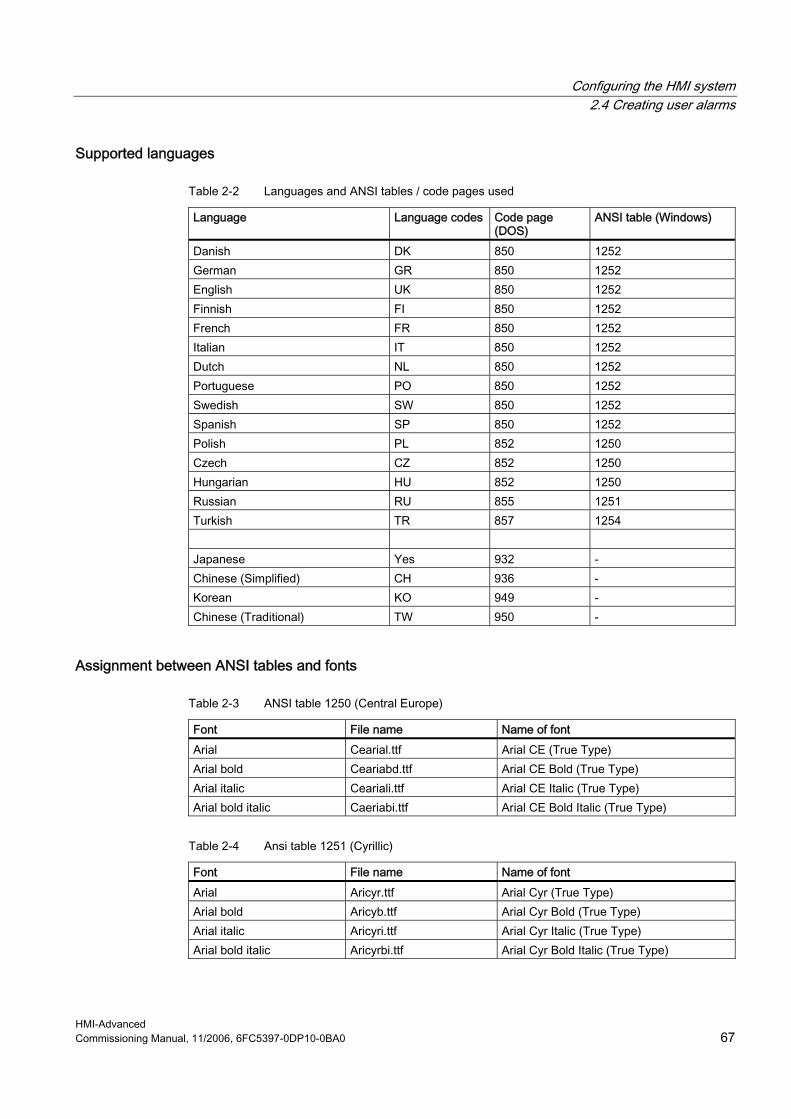
Configuring the HMI system 2.4 Creating user alarms
HMI-Advanced Commissioning Manual, 11/2006, 6FC5397-0DP10-0BA0 67
Supported languages
Table 2-2 Languages and ANSI tables / code pages used
Language Language codes Code page (DOS)
ANSI table (Windows)
Danish DK 850 1252 German GR 850 1252 English UK 850 1252 Finnish FI 850 1252 French FR 850 1252 Italian IT 850 1252 Dutch NL 850 1252 Portuguese PO 850 1252 Swedish SW 850 1252 Spanish SP 850 1252 Polish PL 852 1250 Czech CZ 852 1250 Hungarian HU 852 1250 Russian RU 855 1251 Turkish TR 857 1254 Japanese Yes 932 - Chinese (Simplified) CH 936 - Korean KO 949 - Chinese (Traditional) TW 950 -
Assignment between ANSI tables and fonts
Table 2-3 ANSI table 1250 (Central Europe)
Font File name Name of font Arial Cearial.ttf Arial CE (True Type) Arial bold Ceariabd.ttf Arial CE Bold (True Type) Arial italic Ceariali.ttf Arial CE Italic (True Type) Arial bold italic Caeriabi.ttf Arial CE Bold Italic (True Type)
Table 2-4 Ansi table 1251 (Cyrillic)
Font File name Name of font Arial Aricyr.ttf Arial Cyr (True Type) Arial bold Aricyb.ttf Arial Cyr Bold (True Type) Arial italic Aricyri.ttf Arial Cyr Italic (True Type) Arial bold italic Aricyrbi.ttf Arial Cyr Bold Italic (True Type)

Configuring the HMI system 2.4 Creating user alarms
HMI-Advanced 68 Commissioning Manual, 11/2006, 6FC5397-0DP10-0BA0
Table 2-5 ANSI table 1252 (West Europe)
Font File name Name of font Arial Windows default Arial (True Type) Arial bold Windows default Arial Bold (True Type) Arial italic Windows default Arial Italic (True Type) Arial bold italic Windows default Arial Bold Italic (True Type)
Table 2-6 ANSI table 1254 (Turkish))
Font File name Name of font Arial Trar.ttf Turkish Arial (True Type) Arial bold Trarbd.ttf Turkish Arial Bold (True Type) Arial italic Trari.ttf Turkish Arial Italic (True Type) Arial bold italic Trarbi.ttf Turkish Arial Bold Italic (True Type)
Installing languages !!! Languages that are not included with the standard product must first be installed. An additional tool is implicitly required for Asian languages (e.g. NJWIN). The appropriate fonts are installed automatically with this. When each language module is installed, the tool also installs the appropriate fonts, and all necessary entries are made in the MMC.INI file and in the registry. When commissioning the system, the DLLs, text files (machine data files) and language-dependent INI files are stored in the "\mmc2\language" directory, and the alarm texts are stored in the “\dh\mb.dir” directory.
Language If alarm texts are to be configured in other languages than are already available in the control, then a softkey "language selection" can be configured (refer to Chapter 2.2.4 Softkey, "Configuring a language selection"). The name of the text file is used to assign language-specific user alarm texts. The appropriate code and the extension .com are added to the user file name entered in MBDDE.INI.
Online help for alarms Creating user-specific online help texts is described in the /HE1/ Commissioning Manual, online help.

Configuring the HMI system 2.4 Creating user alarms
HMI-Advanced Commissioning Manual, 11/2006, 6FC5397-0DP10-0BA0 69
2.4.2 Creating user-specific alarm texts
Files supplied with the system The files with the alarm texts in the ASCII format are saved on the PCU hard disk under the following path:
MMC F:\dh\mb.dir\alm_XX.com NCK F:\dh\mb.dir\aln_XX.com PLC F:\dh\mb.dir\alp_XX.com ZYK F:\dh\mb.dir\alz_XX.com CZYK F:\dh\mb.dir\alc_XX.com
In these file names, "X" stands for the code of the appropriate language. The standard files should not be changed by the user in order to store his or her own alarm texts.
Note To prevent a modified MBDDE.INI file from being overwritten when the software is updated, it must be stored in the path designated for that purpose: ..\user\mbdde.ini
Creating user alarms The user can replace the alarm texts supplied by his own texts or add his own texts. To do this, use the Editor available in the area "Start-up" → "HMI" → "Editor". To do this, the additional files must be created in directory f:\dh\mb.dir (MBDDE alarm texts) via the "Services" operating area. The texts from the user files overwrite standard texts with the same alarm number. Alarm numbers that do not already exist in the standard texts are added.
Editor Any ASCII editor (e.g. DOS editor) can be used for editing files. When editing the text files with a different editor, make sure that they are then saved in ASCII format.
Note Changes to the alarm texts only take after the HMI has restarted. When creating text files, make sure that the correct date and time are set on the HMI system. Otherwise, the user texts may not appear on the screen.

Configuring the HMI system 2.4 Creating user alarms
HMI-Advanced 70 Commissioning Manual, 11/2006, 6FC5397-0DP10-0BA0
Activating the alarm text files The alarm texts generated by the user are activated in the file MBDDE.INI in the Section [Textfiles] by the following entries: ... [Textfiles] MMC=F:\dh\mb.dir\alm_ NCK=F:\dh\mb.dir\aln_ PLC=F:\dh\mb.dir\plc_ ZYK=F:\dh\mb.dir\alz_ CZYK=F:\dh\mb.dir\alc_ UserMMC= UserNCK= UserPLC= UserZyk= UserCZyk= ... Example for two additional files (texts for PLC alarms, modified NCK alarm texts) in the MBDDE.INI file: ... User MMC = User NCK = F:\dh\mb.dir\mynck_ User PLC = F:\dh\mb.dir\myplc_ User ZYK = User CZYK = ...
Language-specific nature of alarm texts The name of the text file is used to assign languages to user alarm texts. The appropriate code and the extension .com are added to the user file name entered in mbdde.ini. You will find the appropriate language codes in Table 4-6. If alarm and message texts are created externally, they must be produced with the code pages, ANSI tables, and fonts according to Tables 3-2 to 3-5. The alarm and message texts are stored in the MBDDE alarm texts directory. 1. Convert the old text file to an ANSI text file using "Save As…" in the Windows Editor
(WinWord, Notepad, etc.). 2. Load the new text file and converted old text file into the Windows editor and merge them. 3. Save the newly generated text file and insert it into the directory "MBDDE alarm texts".

HMI-Advanced Commissioning Manual, 11/2006, 6FC5397-0DP10-0BA0 71
Parameterizing machine data 33.1 Handling machine data via the HMI
Overview Specific settings can be made to address manufacturer manufacturer and user requirements by: • Configuring the HMI operator interface using INI files • Parameterizing the control using machine data • Programming PLC Functions
Danger
Changes in the machine data have a considerable influence on the machine. Incorrect configuration of the parameters can endanger human life and cause damage to the machine.
Requirements Access to the machine data operating area can be controlled by key-operated switch or password.
Classification of machine data The machine data is divided into the following areas: • General machine data ($MN ) • Channel-specific machine data ($MC ) • Axis-specific machine data ($MA ) • Display machine data ($MM ) • Drive-specific machine data ($M_) • Machine data control unit: Drive parameters (solution line) • Infeed-machine data: Drive parameters (solution line) A separate list display is provided for each of these areas in which you can view and edit machine data.

Parameterizing machine data 3.1 Handling machine data via the HMI
HMI-Advanced 72 Commissioning Manual, 11/2006, 6FC5397-0DP10-0BA0
The following properties of the machine data are displayed from left to right: • Machine data number • Machine data name, with field index if applicable. • Value of the machine data • Unit of the machine data • Effectiveness
Effectiveness of the machine data The right-hand column indicates when a machine data becomes effective:
so = immediately effective cf = when confirmed via the "Activate MD" softkey re = reset po = POWER ON (NCK Power On reset)
Physical units of the machine data The physical units of machine data are displayed on the right-hand side of the input field:
Display Unit Measured quantity m/s**2 m/s² Acceleration rev/s**3 rev/s³ Acceleration change for the rotating axis kg/m**2 kgm² Moment of inertia mH mH (millihenry): Inductance Nm Nm (Newton meters): Torque us µs (microseconds): Time µA µA (microamperes): Current magnitude µVs µVs (microvolt-seconds): Magnetic flux userdef user-defined: The units are defined by the user.
If the machine data does not use units, no units are displayed. If the data are not available, the "#" symbol is displayed instead of the value. If the value ends in an "H", it is a hexadecimal value.
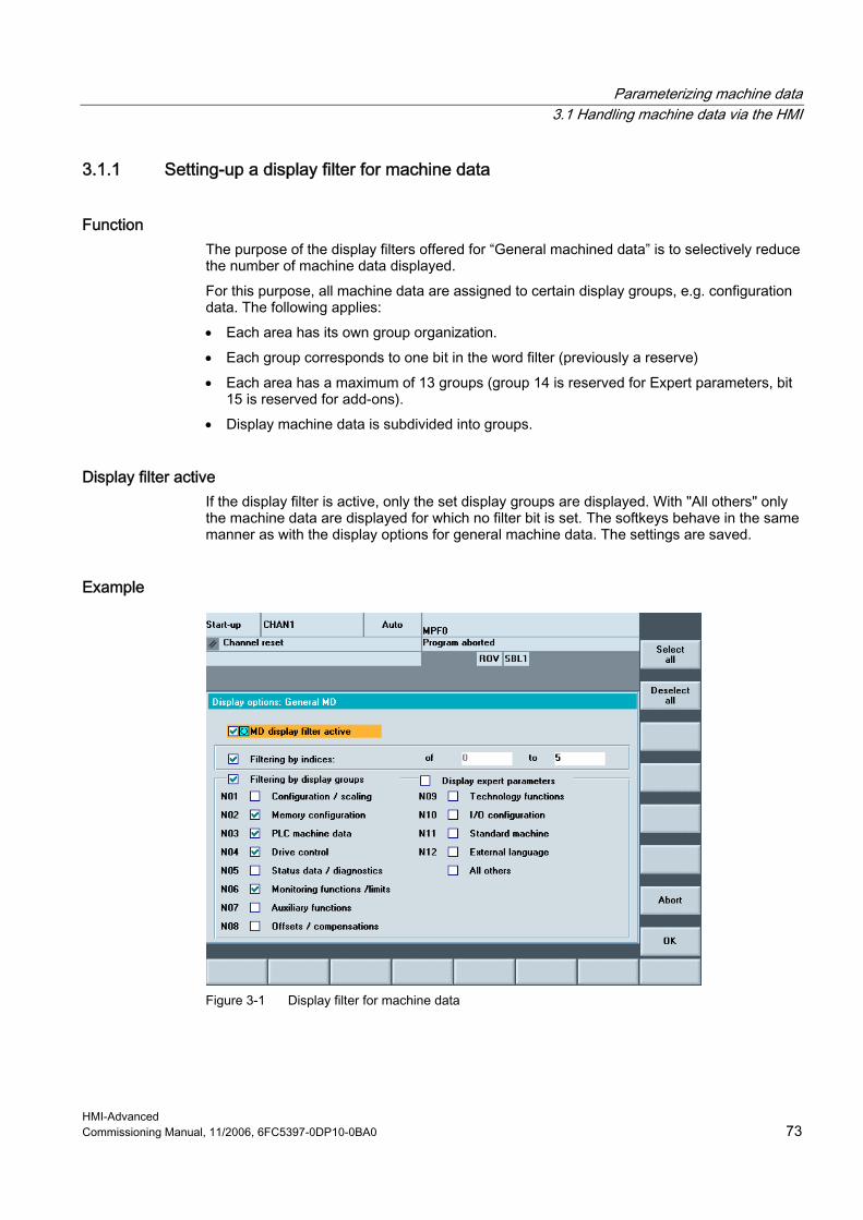
Parameterizing machine data 3.1 Handling machine data via the HMI
HMI-Advanced Commissioning Manual, 11/2006, 6FC5397-0DP10-0BA0 73
3.1.1 Setting-up a display filter for machine data
Function The purpose of the display filters offered for “General machined data” is to selectively reduce the number of machine data displayed. For this purpose, all machine data are assigned to certain display groups, e.g. configuration data. The following applies: • Each area has its own group organization. • Each group corresponds to one bit in the word filter (previously a reserve) • Each area has a maximum of 13 groups (group 14 is reserved for Expert parameters, bit
15 is reserved for add-ons). • Display machine data is subdivided into groups.
Display filter active If the display filter is active, only the set display groups are displayed. With "All others" only the machine data are displayed for which no filter bit is set. The softkeys behave in the same manner as with the display options for general machine data. The settings are saved.
Example
Figure 3-1 Display filter for machine data
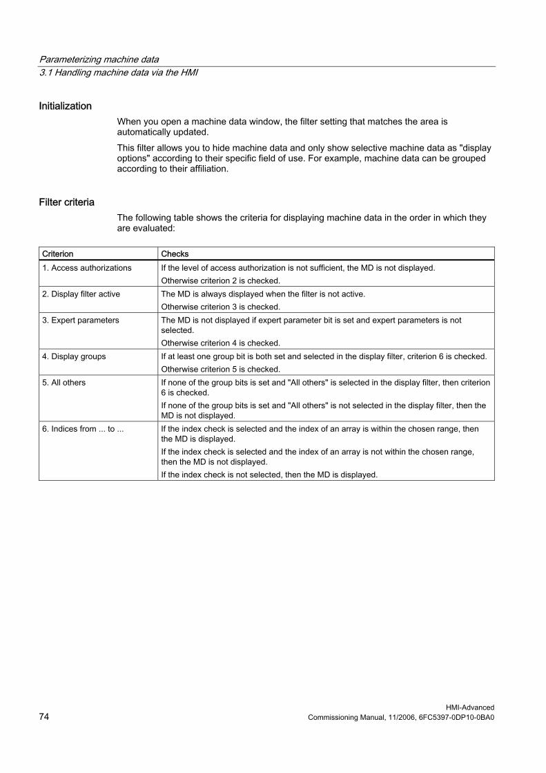
Parameterizing machine data 3.1 Handling machine data via the HMI
HMI-Advanced 74 Commissioning Manual, 11/2006, 6FC5397-0DP10-0BA0
Initialization When you open a machine data window, the filter setting that matches the area is automatically updated. This filter allows you to hide machine data and only show selective machine data as "display options" according to their specific field of use. For example, machine data can be grouped according to their affiliation.
Filter criteria The following table shows the criteria for displaying machine data in the order in which they are evaluated:
Criterion Checks 1. Access authorizations If the level of access authorization is not sufficient, the MD is not displayed.
Otherwise criterion 2 is checked. 2. Display filter active The MD is always displayed when the filter is not active.
Otherwise criterion 3 is checked. 3. Expert parameters The MD is not displayed if expert parameter bit is set and expert parameters is not
selected. Otherwise criterion 4 is checked.
4. Display groups If at least one group bit is both set and selected in the display filter, criterion 6 is checked. Otherwise criterion 5 is checked.
5. All others If none of the group bits is set and "All others" is selected in the display filter, then criterion 6 is checked. If none of the group bits is set and "All others" is not selected in the display filter, then the MD is not displayed.
6. Indices from ... to ... If the index check is selected and the index of an array is within the chosen range, then the MD is displayed. If the index check is selected and the index of an array is not within the chosen range, then the MD is not displayed. If the index check is not selected, then the MD is displayed.

Parameterizing machine data 3.1 Handling machine data via the HMI
HMI-Advanced Commissioning Manual, 11/2006, 6FC5397-0DP10-0BA0 75
3.1.2 Creating user views
User views User views are user-specific groups of machine data. They are used to call all relevant machine data in a certain operating state from various areas for processing.
Overview of machine data You can include the following machine data in the user view:
• General machine data • Channelspecific machine data • Axis-specific machine data • General setting data • Channel-specific setting data • Axis-specific setting data • General display machine data • Channel-specific display machine data • Machine data for SIMODRIVE drives (powerline) • Machine data for SINAMICS drives, for Control Units, I/O modules and infeed
Example Creating user view TEST01: 1. Select "New View". An empty window is opened in order to insert the appropriate
machine data and comment lines. 2. In order to insert a comment, select "Insert Text...", and enter a text, for example, "text
line 1". Acknowledge using the <INPUT> key in order to accept the text. 3. In order to insert a machine data, select "Insert Data...". Select the machine data area,
e.g. "Axis-specific machine data". The corresponding range of numbers 30 000 - 38 000 is displayed in the list:
4. Mark machine data 32 000. In order to transfer the machine data into the user view, press the softkey "Insert before/after line".
5. For additional machine data, proceed in the same way or user "Search": Within a range of numbers, you can also mark and insert a machine data directly using "Search".
6. In order to complete the selection, press the softkey "<<" to return to the window "Edit View".

Parameterizing machine data 3.1 Handling machine data via the HMI
HMI-Advanced 76 Commissioning Manual, 11/2006, 6FC5397-0DP10-0BA0
Result:
Figure 3-2 Example: User view
The following softkeys are available to edit the user view: 1. You can shift lines using the softkeys "Up" or "Down" - correspondingly, lines are deleted
with "Delete line". 2. Select "Properties" in order to enter descriptive text for the machine data or to modify
existing text. The descriptive text is displayed at the bottom in the info line, e.g. "Channel name".
3. To save the user view, select "Manage views". Enter a name, e.g. Test01 and accept it using the <INPUT> key.
4. In order to display the user view, select "Assign Softkey" and enter a text for the softkey labeling.
Figure 3-3 Assigning softkeys for direct selection
Parameterizing machine data 3.2 Parameterizing the control using machine data
HMI-Advanced Commissioning Manual, 11/2006, 6FC5397-0DP10-0BA0 77
Note There are 6 softkeys that can be used to saved user views. In the "Axis" field it is possible to enter the axis number or select the appropriate axis from a list. Axis number or axis name is marked with a "*" in the user view until their assignment changes.
3.2 Parameterizing the control using machine data
3.2.1 Fine work offset and base offset
Function This function refers to the offset in the "Settable work offset" and "Basic work offset" screen forms. Another column for the fine offset is inserted alongside the column for entering the offsets. The inputs are checked against the display machine data.
MD 9203: USER_CLASS_WRITE_FINE Access level for protection MD 9451: MM_WRITE_ZOA_FINE_LIMIT Absolute value of the change
Actual value display: settable zero system Via MD 9424: MA_COORDINATE_SYSTEM can be used to specify how the actual values are displayed: • Position of the workpiece coordinate system (programmed position, corresponding to
default setting) or • Take-up position of the active tool relative to the workpiece zero.
MD 9424 = 0 Display in workpiece coordinate system, WCS (default) MD 9424 = 1 Display in the settable zero system, SZS (fixture position of the active
tool) Example:
Program WCS display SZS display N110 X100 N110 X100 N120 X0 N130 $P_PFRAME=CTRANS(X,10) N140 X100 N150 ...
100 0 0 100
100 0 0 110

Parameterizing machine data 3.2 Parameterizing the control using machine data
HMI-Advanced 78 Commissioning Manual, 11/2006, 6FC5397-0DP10-0BA0
Note To set the actual-value display: see the machine manufacturer's information.
3.2.2 Machine data for setting actual value, scratching, PRESET
Function The behavior of the Scratching and Set actual value, PRESET functions is influenced by a number of machine data. The selected settings also affect operation (Display of softkeys and values, saving of input values). With the introduction of system frames, two variants are available for the functions. The variants are differentiated by a channel-specific machine data: MD 28082: $MC_SYSTEM_FRAME_MASK
Bit: 0 Actual value setting, scratching 1 External work offset 2 TCARR, PAROT 3 TOROT, TOFRAME 4 Workpiece reference points 5 Cycles 6 Transformations
Version 1 without system frame: The MD does not exist or Bit 0 for the system frame for scratching or actual value setting is not set. Version 2 with system frame: Bit 0 for the system frame for scratching and actual value setting is set in the MD. Display machine data MD 9422: $MM_MA_PRESET_MODE defines the PRESET/basic offset function in JOG mode. 0: No softkey 1: The old PRESET in the machine operating area (default) 2: Actual value setting 3: Actual value setting (see online help)
Note To hide the PRESET, Set actual value, and Scratching softkeys, MD 9220: $MM_USER_CLASS_PRESET can also be set.
Reference: Operating Manual HMI-Advanced

Parameterizing machine data 3.2 Parameterizing the control using machine data
HMI-Advanced Commissioning Manual, 11/2006, 6FC5397-0DP10-0BA0 79
Actual value setting • Actual value setting with system frame:
G500 active: The values are written to the system frame. G500 not active: An error message is output.
• Actual value setting without system frame: G500 active (adjustable frames reset): Values are written to the first basic frame according to the entry in display MD 9245: $MM_MA_PRESET_FRAMEIDX = Index of basic frame G500 not active: An error message is output.
Scratching When this is selected the active frame is offered. A different frame can be selected by means of an entry in the "Work offset" field. • Scratching with system frame:
With G500 in the "Work offset" field, the values are written to the system frame. With a value other than G500 in the "Work offset" field, the values are written to the frame defined in the field. You cannot choose any tool other than the one in the spindle. If there is no tool in the spindle, you can choose any tool you want.
• Scratching without system frame: With G500 in the "Work offset" field, the values are written to the first basic frame. Values are written to the specified basic frame according to the entry in display MD 9245: $MM_MA_PRESET_FRAMEIDX = Index of basic frame With a value other than G500 in the "Work offset" field, the values are written to the frame defined in the field. You can select any tool you want.
3.2.3 Set tool offset to be active immediately
Function Wit the display MD 9440: ACTIVATE_SEL_USER_DATA can be used to specify that changes in the tool offsets are activated immediately even if the NC channel is not in "Reset" or "Stop" state. This function is always active.
Caution The offset is applied after NC Start of the Reset in response to the next programmed axis movement in the part program.
References: Function Manual Basic Functions: Axes, coordinate systems, frames (K2)
Parameterizing machine data 3.2 Parameterizing the control using machine data
HMI-Advanced 80 Commissioning Manual, 11/2006, 6FC5397-0DP10-0BA0
3.2.4 Specifying the machine and rotary axis position
Singularities in special kinematics and robots In the Cartesian point-to-point method (PTP) in workpiece coordinates, the position of the machine axes is ambiguous in some places. In order to define these singularities without ambiguity, the machine position STAT and the axes position TU are defined in addition to the workpiece coordinates for this type of transformation (e.g. 5-axis transformation).
Setting the number base The STAT and TU values are displayed in the axis screens (actual-value window, broad actual-value window with feed and zoom display) and entered in the MDA editor during the teach-in procedure. Whether the values in STAT and TU are displayed in binary, decimal, or hexadecimal format is specified via the display machine data:
MD 9242: MA_STAT_DISPLAY_BASE Numerical basis for display of moving joint STAT MD 9243: MA_TU_DISPLAY_BASE Numerical basis for display of rotary axis position TU
Possible values are: 02 Display as binary value 10 Display as decimal value 16 Display as hexadecimal value
These settings apply to both the actual-value window and the editor window.
Example In the NC program, the movement of axes from X120 Y20 Z-50 to X200 Y200 Z-120 looks like this in binary display: X=120 Y=20 Z=-50 STAT='B010' TU'B011101' X=200 Y200 Z=-120 STAT'B110' TU='B011111'
3.2.5 Memory for cycles in the DRAM
Overview Cycles can be stored in the DRAM of the NCU. This makes more SRAM memory available to the user for parts programs and workpieces.
Function Under "Start-up" → "NC" → "NC Memory", the user interface for HMI-Advanced offers users with corresponding access authorizations the possibility of determining the utilization of

Parameterizing machine data 3.2 Parameterizing the control using machine data
HMI-Advanced Commissioning Manual, 11/2006, 6FC5397-0DP10-0BA0 81
DRAM and to adjust its size via MD 18351: MM_DRAM_FILE_MEM_SIZE. A change to the DRAM memory causes a complete reorganization of the NCK memory.
Notice You must save all relevant data before changing the memory sizes. If machine data is changed then this results in a re-organization of the NCK memory.
Cycles saved in the DRAM Via MD 11290: DRAM_FILESYSTEM_MASK can be used to set which objects should be loaded in the DRAM:
Bit 0-n = 0: The data for the specified directory is to be stored in the SRAM. = 1: The data for the specified directory is to be stored in the DRAM.
Depending on MD 11291: DRAM_FILESYST_SAVE_MASK a copy is kept in the FFS on the NC card.
Bit 0 CST directory (Siemens cycles) Bit 1 CMA directory (machine manufacturer cycles) Bit 2 CUS directory (user cycles)
Saving in the Flash File System (FFS) MD 11291: DRAM_FILESYST_SAVE_MASK can be used to set which objects should be saved in the DRAM on the FFS:
Bit 0-n = 0: No files are saved. If the control is switched off, the data on the NCK is
lost. = 1: The data in the DRAM is saved in the FFS of the NC card. Bit 0 CST directory (Siemens cycles) Bit 1 CMA directory (machine manufacturer cycles) Bit 2 CUS directory (user cycles)
Saving in the FFS avoids having to reload the objects when booting.
Notice Direct changes to objects stored in the DRAM and saved in the FFS are not enabled. Only cycles for saving can be specified in the FFS. Any changes that are required must be made before loading onto HMI-Advanced. Direct changes to objects in the DRAM that are not saved on the FFS are lost on Power Off.

Parameterizing machine data 3.2 Parameterizing the control using machine data
HMI-Advanced 82 Commissioning Manual, 11/2006, 6FC5397-0DP10-0BA0
3.2.6 Redefining protection levels for NC data
Function The preset protection levels can be modified in the definition file. For machine data, only lower protection levels than the configured protection level are permitted; for setting data, higher levels are also permitted. The file becomes active when the next _N_INITIAL_INI is read in. Different protection levels are specified for writing or reading (part program or PLC). Example:
_N_DEF_DIR/_N_SGUD_DEF ; File for global variables ; $PATH=/_N_DEF_DIR REDEF $MA_CTRLOUT_SEGMENT_NR APR 7 APW 4 MD 30100 ; (APR ... Read access) REDEF $MA_ENC_SEGMENT_NR APR 2 APW 2 MD 30210 ; (APW ... Write access) REDEF $SN_JOG_CONT_MODE_LEVELTRIGGRD APR 2 APW 2 M30 SD 41050
MD 30100: $MA_CTRLOUT_SEGMENT_NR has protection level 2/7, i.e. protection level 2 is required for write access (corresponding to password) and protection level 7 for read access. In order to access the machine data area, key-operated switch setting 3 or higher is required.
Undoing the protection level change In order to undo protection level changes, the original values have to be restored. Example:
_N_DEF_DIR/__N_SGUD_DEF ; File for global variables ; $PATH=/_N_DEF_DIR REDEF $MA_CTRLOUT_SEGMENT_NR APR 7 APW 2 ; (APR ... Read access) REDEF $MA_ENC_SEGMENT_NR APR 0 APW 0 ; (APW ... Write access) REDEF $SN_JOG_CONT_MODE_LEVELTRIGGRD APR 7 APW 7 M30
Parameterizing machine data 3.2 Parameterizing the control using machine data
HMI-Advanced Commissioning Manual, 11/2006, 6FC5397-0DP10-0BA0 83
Definition files for REDEF For programming REDEF commands - the same as for the GUD definitions - separate definition files exist, which are evaluated when the control boots.
/_N_DEF_DIR/_N_UACCESS_DEF // Definition file for protection level instructions of
the end user /_N_DEF_DIR/_N_MACCESS_DEF // Definition file for protection level instructions of
the manufacturer /_N_DEF_DIR/_N_SACCESS_DEF // Definition file for protection level instructions for
Siemens system applications (e.g. standard cycles, ShopMill, ...)
A additional Siemens definition file, which is used to configure the system, is saved on the PCMCIA card or CF card in the NC system software.
Note Compatibility If the access to machine data that was authorized by the command "REDEF <machine data>APR <protection level> APW <protection level>", is declined with alarm 15420, you must proceed as follows: When the function is activated or when the system is upgraded, the REDEF commands from existing GUD definition files must be imported into the new definition files _N_SACCESS_DEF, _N_MACCESS_DEF, _N_UACCESS_DEF.
Protection levels for NC commands Certain NC commands can be linked to protection levels to restrict their execution to authorized personnel only. If no corresponding execution authorization exists, the processing of the part program is aborted with alarm 14018. The preset for the current execution authorization corresponds to the access authorization on the control unit, i.e. key-operated switch setting 0 to 3 or a password for end users as far as Siemens. References: Programming Manual, Chapter "Protection levels for NC commands".
3.2.7 Change access authorization for softkey "Basis WO"
Parameters operating area MD 9247: $MM_USER_CLASS_BASE_ZERO_OFF_PA can be used to set the access level from which the "Base WO" softkey is displayed in the "Work offset" window in the "Parameters" operating area. At the same time, the basic frames are also displayed or hidden in the "Work offset" window and in the "Active WO + compensations" window.
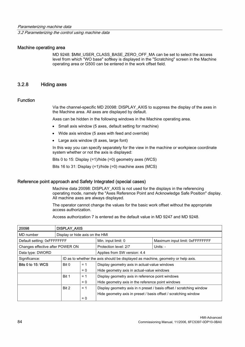
Parameterizing machine data 3.2 Parameterizing the control using machine data
HMI-Advanced 84 Commissioning Manual, 11/2006, 6FC5397-0DP10-0BA0
Machine operating area MD 9248: $MM_USER_CLASS_BASE_ZERO_OFF_MA can be set to select the access level from which "WO base" softkey is displayed in the "Scratching" screen in the Machine operating area or G500 can be entered in the work offset field.
3.2.8 Hiding axes
Function Via the channel-specific MD 20098: DISPLAY_AXIS to suppress the display of the axes in the Machine area. All axes are displayed by default. Axes can be hidden in the following windows in the Machine operating area. • Small axis window (5 axes, default setting for machine) • Wide axis window (5 axes with feed and override) • Large axis window (8 axes, large font) In this way you can specify separately for the view in the machine or workpiece coordinate system whether or not the axis is displayed: Bits 0 to 15: Display (=1)/hide (=0) geometry axes (WCS) Bits 16 to 31: Display (=1)/hide (=0) machine axes (MCS)
Reference point approach and Safety Integrated (special cases) Machine data 20098: DISPLAY_AXIS is not used for the displays in the referencing operating mode, namely the "Axes Reference Point and Acknowledge Safe Position" display. All machine axes are always displayed. The operator cannot change the values for the basic work offset without the appropriate access authorization. Access authorization 7 is entered as the default value in MD 9247 and MD 9248.
20098 DISPLAY_AXIS MD number Display or hide axis on the HMI Default setting: 0xFFFFFFFF Min. input limit: 0 Maximum input limit: 0xFFFFFFFF Changes effective after POWER ON Protection level: 2/7 Units: - Data type: DWORD Applies from SW version: 4.4 Significance: ID as to whether the axis should be displayed as machine, geometry or help axis. Bits 0 to 15: WCS Bit 0 = 1
= 0 Display geometry axis in actual-value windows Hide geometry axis in actual-value windows
Bit 1 = 1 = 0
Display geometry axis in reference point windows Hide geometry axis in the reference point windows
Bit 2 = 1 = 0
Display geometry axis in n preset / basis offset / scratching window Hide geometry axis in preset / basis offset / scratching window
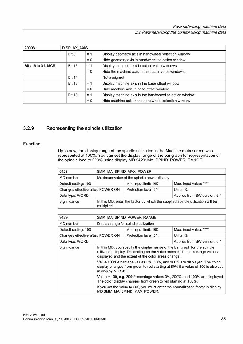
Parameterizing machine data 3.2 Parameterizing the control using machine data
HMI-Advanced Commissioning Manual, 11/2006, 6FC5397-0DP10-0BA0 85
20098 DISPLAY_AXIS Bit 3 = 1
= 0 Display geometry axis in handwheel selection window Hide geometry axis in handwheel selection window
Bits 16 to 31: MCS Bit 16 = 1 = 0
Display machine axis in actual-value windows Hide the machine axis in the actual-value windows.
Bit 17 Not assigned Bit 18 = 1
= 0 Display machine axis in the base offset window Hide machine axis in base offset window
Bit 19 = 1 = 0
Display machine axis in the handwheel selection window Hide machine axis in the handwheel selection window
3.2.9 Representing the spindle utilization
Function Up to now, the display range of the spindle utilization in the Machine main screen was represented at 100%. You can set the display range of the bar graph for representation of the spindle load to 200% using display MD 9429: MA_SPIND_POWER_RANGE.
9428 $MM_MA_SPIND_MAX_POWER MD number Maximum value of the spindle power display Default setting: 100 Min. input limit: 100 Max. input value: **** Changes effective after: POWER ON Protection level: 3/4 Units: % Data type: WORD Applies from SW version: 6.4 Significance In this MD, enter the factor by which the supplied spindle utilization will be
multiplied.
9429 $MM_MA_SPIND_POWER_RANGE MD number Display range for spindle utilization Default setting: 100 Min. input limit: 100 Max. input value: **** Changes effective after: POWER ON Protection level: 3/4 Units: % Data type: WORD Applies from SW version: 6.4 Significance In this MD, you specify the display range of the bar graph for the spindle
utilization display. Depending on the value entered, the percentage values displayed and the extent of the color areas change. Value 100:Percentage values 0%, 80%, and 100% are displayed. The color display changes from green to red starting at 80% if a value of 100 is also set in display MD 9428. Value > 100, e.g. 200:Percentage values 0%, 200%, and 100% are displayed. The color display changes from green to red starting at 100%. If you set the value to 200, you must enter the normalization factor in display MD $MM_MA_SPIND_MAX_POWER.
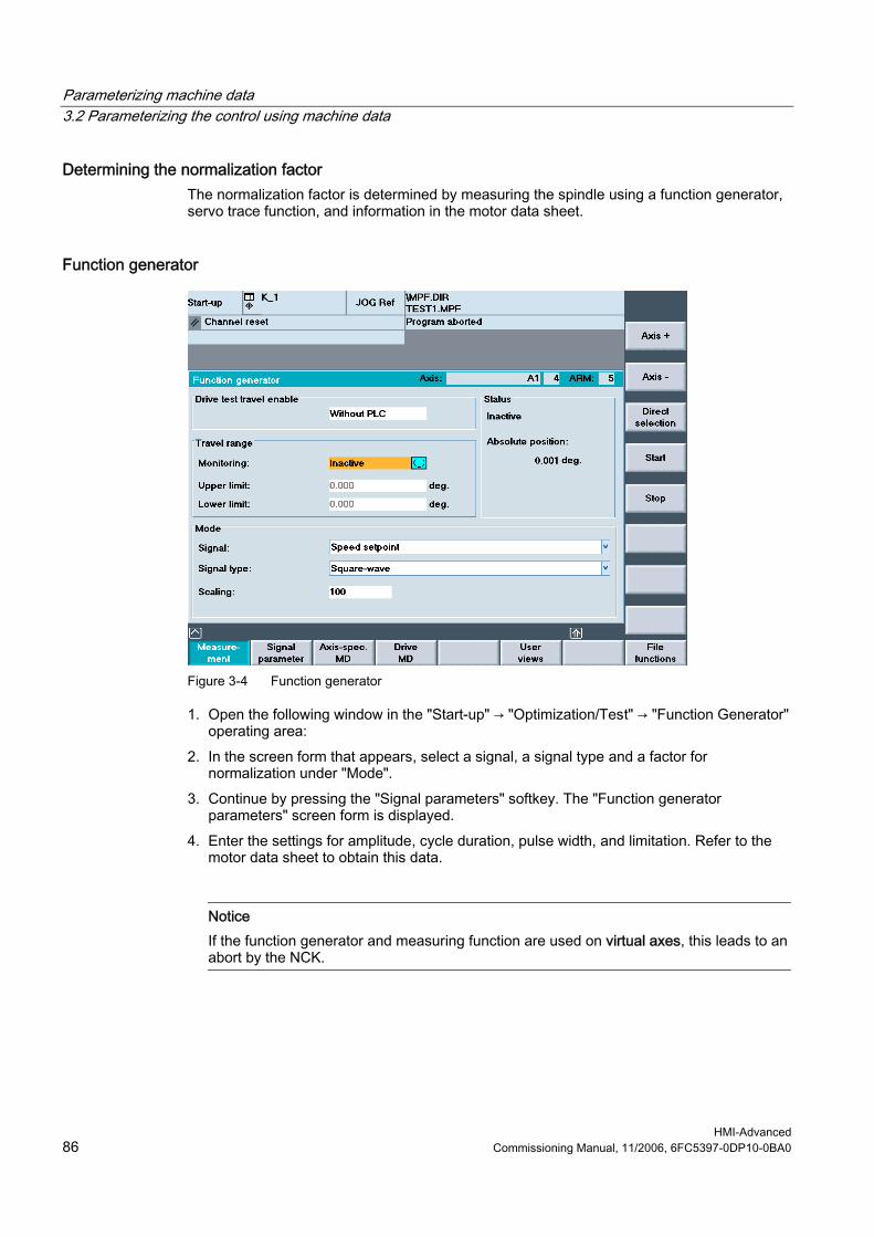
Parameterizing machine data 3.2 Parameterizing the control using machine data
HMI-Advanced 86 Commissioning Manual, 11/2006, 6FC5397-0DP10-0BA0
Determining the normalization factor The normalization factor is determined by measuring the spindle using a function generator, servo trace function, and information in the motor data sheet.
Function generator
Figure 3-4 Function generator
1. Open the following window in the "Start-up" → "Optimization/Test" → "Function Generator" operating area:
2. In the screen form that appears, select a signal, a signal type and a factor for normalization under "Mode".
3. Continue by pressing the "Signal parameters" softkey. The "Function generator parameters" screen form is displayed.
4. Enter the settings for amplitude, cycle duration, pulse width, and limitation. Refer to the motor data sheet to obtain this data.
Notice If the function generator and measuring function are used on virtual axes, this leads to an abort by the NCK.

Parameterizing machine data 3.2 Parameterizing the control using machine data
HMI-Advanced Commissioning Manual, 11/2006, 6FC5397-0DP10-0BA0 87
Servo trace function
Figure 3-5 Servo trace: Main screen
1. Open the Trace function main screen by pressing the "Drive/servo" softkey followed by the "Servo trace" softkey in the "Start-up" operating area.
2. Select the variables to be measured from the drop-down list in the "Signal selection" area. Refer to the motor data sheet to obtain the settings for the measuring period and trigger time. After parameterization, start the measurement by pressing the "Start" softkey.
3. Select the constant power range or constant torque range in order to calculate the normalization factor using these data.
Example: In the diagram, the measured power is 10.5 kW.
Figure 3-6 Servo trace: Evaluation
Parameterizing machine data 3.2 Parameterizing the control using machine data
HMI-Advanced 88 Commissioning Manual, 11/2006, 6FC5397-0DP10-0BA0
If the utilization display is to indicate 100% for nominal data and higher values at operation above the nominal working point, the normalization factor setting can be calculated from the motor data or from the diagram and measurement as follows: MA_SPIND_MAX_POWER = Maximum_of_the_measured_power / rated power_S1 * 100 MA_SPIND_MAX_POWER = 10500W / 7000W * 100 = 150 Enter the factor 150 in the machine data.
3.2.10 Inverting the spindle icon of the spindle display
Function The display of the spindle icon can be inverted using the channel-specific machine data MD 9033: MA_DISPL_INVERT_DIR_SPIND_M3: Normal or inverted display is possible. For example, if you want the same icon to be displayed at M4 for the counter-spindle as at M3 for the main spindle, set bit[n]=1 (see inverting M3/M4 at the control interface).
9033 MA_DISPL_INVERT_DIR_SPIND_M3 MD number Spindle rotation direction display Default value: 0x0000 Min. input value: 0x0000 Max. input value: 0x7FFFFFFF Change effective: IMMEDIATE Protection level (R/W) 3/4 Units: - Data type: LONG Applies from SW version: 6.2 Significance Spindle rotation direction display:
Bit[n]=0 M3 is displayed as clockwise rotation in the icon Bit[n]=1 M3 displayed as clockwise rotation in the icon n = spindle number – 1 (i.e. bit 0 is spindle S1) Note: For an appropriately set MD 9014: USE_CHANNEL_DISPLAY_DATA MD 9033 can be managed channel-specifically in the NC.
Parameterizing machine data 3.3 Creating plain text for PLC machine data
HMI-Advanced Commissioning Manual, 11/2006, 6FC5397-0DP10-0BA0 89
3.3 Creating plain text for PLC machine data
Overview Application-specific and language-dependent plain text can be configured depending on the version [Index] for PLC machine data. The text files with the name NCTEA_xx.TXT (xx = language code GR, UK, ...) can be created in the following directories: user\language, add_on\language oem\language Entry in the following format: <Number of entries> ; number of entries <MD number>[<Index>] <Text> ; Number[Index] text
Example
14510[i] User data (INT) i = 0 ... 255 14514[i] User data (FLOAT) i = 0 ... 31 14516[i] User data (HEX) i = 0 ... 255
Entry in the file NCTEA_GR.TXT: 3 14510[0] My integer text for PLC-MD 14510.0 14514[0] Text for float data 14514.0 14516[2] This is the text in HEX for MD14516.2 result in the display: 14510[0] My integer text for PLC-MD 14510.0 14514[0] Text for float data 14514.0 14516[2] This is the text in HEX for MD14516.2
Note PLC operating messages are created and handled in the same way as alarm texts.
Language code for the text files according to the Table: "Languages and ANSI tables / code page used".
See also Structure of user-specific alarms (Page 66)

Parameterizing machine data 3.3 Creating plain text for PLC machine data
HMI-Advanced 90 Commissioning Manual, 11/2006, 6FC5397-0DP10-0BA0
HMI-Advanced Commissioning Manual, 11/2006, 6FC5397-0DP10-0BA0 91
Programming PLC Functions 44.1 Activating the data transfer between the PLC and NCK
Function Data transfer from/to NCK with the following properties can be started via the PLC: • Data transfer from the hard disk to or from the NCK (workpiece directory, part program,
etc.) using job lists. • The "Job list" function is used in HMI-Advanced to process part programs - e.g. loading,
unloading, selecting or executing from the hard disk. By means of the interface between the PLC and HMI in DB19, the PLC issues jobs to the HMI that initiate a data transfer between the HMI (PCU hard disk) and NCK. Specifying the user control file: DB19.DBB16 (PLC → HMI)
Bit 7 Bit 6 Bit 5 Bit 4 Bit 3 Bit 2 Bit 1 Bit 0 Always = 1 PLC index for the user control file ; value: 1 - 127
Specifying the job list: DB19.DBB17 (PLC → HMI)
Bit 7 Bit 6 Bit 5 Bit 4 Bit 3 Bit 2 Bit 1 Bit 0
PLC line offset in the user control file; value: 1 - 255
Job byte of PLC: DB19.DBB13 (PLC → HMI)
Bit 7 Bit 6 Bit 5 Bit 4 Bit 3 Bit 2 Bit 1 Bit 0 Selection Load Unload
Acknowledgment byte from HMI for the current data transfer status: DB19.DBB26 (HMI → PLC)
Bit 7 Bit 6 Bit 5 Bit 4 Bit 3 Bit 2 Bit 1 Bit 0 Selection Load Unload Active Error OK res. PLC

Programming PLC Functions 4.1 Activating the data transfer between the PLC and NCK
HMI-Advanced 92 Commissioning Manual, 11/2006, 6FC5397-0DP10-0BA0
Notice Machine manufacturer See machine manufacturer's specifications.
References: • Operating Manual HMI-Advanced • Function Manual Basic Functions: Various NC/PLC interface signals and functions (A2)
Job processing A PLC job is processed according to the following scheme: • The PLC may only initiate a job in the job byte if the acknowledgment byte is 0. • The HMI mirrors the job (excluding the parameter set) in the acknowledgment byte
(signaling to the PLC that its job is being processed). The PLC receives a "job active" signal for an unfinished job.
• Once the operation is finished (without error or with error), the PLC must respond again and delete the job byte.
• The HMI then sets the acknowledgement byte to 0. This ensures a sequential procedure.
User control file The names of the job lists to be executed are stored in control file PLC_IN_OUT_xxx.TEA in the display machine data directory (/BD.DIR) on the HMI (= PCU hard disk), where "xxx" represents a number between 001 and 127.The file contains a maximum of 127 references to job lists. Users should create the control file. The PLC sets an index (1 - 127) via DB19.DBB16, which determines the control file in which the job list names are stored: • Example: User control file PLC_IN_OUT_003.TEA
N1 /WKS.DIR/OTTO.WPD/OTTO.JOB N2 /WKS.DIR/WELLE.WPD/KANAL1.JOB N3 ... N4 ... The line numbers N... can be omitted. The file can be edited.
• Example: Loading a job list – Existing file PLC_IN_OUT_003.TEA with the following entries: N1 job list A N2 job list B N3 job list C – Acknowledgement byte DB19.DBB26=0 – Defining the PLC index for the control file (DB 19.DBB16=131) – Defining the PLC line offset 2 (DB 19.DBB17=2) – PLC job: Loading (DB 19.DBB13.6=1)

Programming PLC Functions 4.1 Activating the data transfer between the PLC and NCK
HMI-Advanced Commissioning Manual, 11/2006, 6FC5397-0DP10-0BA0 93
– Job list B is loaded – HMI signals to the PLC: Job list is loaded (DB19.DBB26.6=1)
Note This function is not available if the "Machine" operating area is suppressed from the HMI startup.
Error IDs at the PLC The HMI outputs the following error IDs to the PLC via DB19.DBB27:
Value Significance
0 No error 1 Invalid number for control file. (value in DB19.DBB16 < 127 or invalid) 2 Unable to read DB19.DBB15 3 Control file /BD.DIR/PLC_IN_OUT_xxx.TEA not found. (value in DB19.DBB16 invalid) 4 Invalid index in control file. (incorrect value in DB19.DBB17) 5 Selected job list in control file could not be opened. 6 Error in job list (job list interpreter returns error) 7 Job list interpreter returns empty job list 9 Error while executing job list
Conflict resolution When a job list is executed manually (via operator input), prompts can occur in the protocol, e.g. if an MPF file is located both on the NC as well as on a hard disk and the two MPF files are different. The default setting is "yes," i.e., all prompts are responded to with Yes. If "no", all prompts are responded to with No. The default setting for the response is "yes", i.e., all prompts are responded to with Yes. If "no", all prompts are responded to with No. The response to the prompt is set in the file MASCHINE.INI: [PLC_REQUEST] DefaultAnswer=yes
Multiple operator panel fronts/NCUs M:N (only SINUMERIK powerline) In an m:n system, HMI-Advanced is assigned to a netmaster NCU/PLC in NETNAMES.INI. The bus address of the NCU is configured in the [param network] section. e.g.: [param network] netmaster=NCU_LINKS This setting for the netmaster NCU/PLC means that data transfer is only activated by the NCU/PLC with the symbolic name NCU_LEFT.

Programming PLC Functions 4.2 Transferring the actual task number of the HMI to the PLC
HMI-Advanced 94 Commissioning Manual, 11/2006, 6FC5397-0DP10-0BA0
4.2 Transferring the actual task number of the HMI to the PLC
Task number A task describes the position at which an operating area is attached in the HMI area menu, i.e., the highest level.
Softkey bars The following fixed relationship exists between softkey bars of the area menu and tasks: 1. Softkey bar:
Softkey 1 2 3 4 5 6 7 8 Task number 0 1 2 3 4 5 6 7
2. Softkey bar:
Softkey 1 2 3 4 5 6 7 8 Task number 8 9 10 11 12 13 14 15
3. Softkey bar:
Softkey 1 2 3 4 5 6 7 8 Task number 16 17 18 19 20 21 22 23
Which application is assigned to which task number is stored/configured in the [TaskConfiguration] section in the REGIE.INI file (see Chapter 2.4.22). A fourth softkey bar can be used for OEM applications:
Softkey 1 2 3 4 5 6 7 8 Task number 96 97 98 99 100 101 102 103
Task numbers 24 to 95 are already reserved for child tasks of standard applications or for specific OEM tasks. The associated label texts can be entered in the language-dependent re_xx.ini files.
Application For manufacturer-configured user interfaces, proper concurrence of key strokes on the machine control panel and the displayed operating areas/screens is essential. Example: The "Move unit" function is selected in a screenform. On the MCP are "forward" and "backward" traversing keys, which are used to move the unit in real time. To prevent a new screen from being displayed before the traversing key movement has been completed, due to an operating area switchover in the HMI, for example, the PLC is always able to know and check the current task number.

Programming PLC Functions 4.2 Transferring the actual task number of the HMI to the PLC
HMI-Advanced Commissioning Manual, 11/2006, 6FC5397-0DP10-0BA0 95
Configuration The current task number is transferred to the PLC in a data block section that can be specified as a string in the display MD 9032: HMI_MONITOR as follows: DBxx.DBByy with: xx is the number of a data block yy is the byte number of the 1st byte of the transfer area (word limit) The transfer area is 8 bytes long, the transfer is made in the 1st byte. Bytes 2 to 8 are reserved.
Note Check that the specified area is not already occupied by input bytes, output bytes or flag bytes. The block number and the byte area are not checked.
Updating The task number in the first byte is updated for: • At every task change by the HMI • When the connection is changed to a different NC in M:N For the duration of indeterminate states (e.g. during changeover to another NC in M:N), special value 255 is transferred as the task number.
Range of values The task number can assume values from 0 to 95, including the operating areas configured by the user. As a result, all visible tasks of the main menu (0 to 31) and the hidden child tasks (32 to 95) are displayed.
Programming PLC Functions 4.3 Channel /spindle selection via the PLC
HMI-Advanced 96 Commissioning Manual, 11/2006, 6FC5397-0DP10-0BA0
4.3 Channel/spindle selection via the PLC
Channel selection Channel selection or display is initiated as follows (display in "Channel name" field): DB 19, DBB 32 = 01000001 [binary] channel selection DB 19, DBB 33 = <channel number> FF for next channel
Spindle selection Spindle selection is initiated as follows (display in spindle window): DB 19, DBB 32 = 01000010 [binary] spindle selection DB 19, DBB 33 = <spindle number> spindle number to be displayed
Error codes The following error codes, which provide information to the HMI about errors during the function request of the PLC, are stored in DB 19.DBB 36:
Value Significance 0 No error 1 No function number (DBB32 bit 0-5) 2 Invalid parameter 3 Error when writing to HMI-internal variable 10 Channel not present (DBB33)
Acknowledgement mechanism between PLC ↔ HMI Via DB19.DBB32 bits 6, 7, there is an acknowledgment mechanism that ensures that the HMI and the PLC coordinate the channel selection: The PLC sets Bit 6 to 1 = "Function request". The function request can only be set by the PLC if bits 6 and 7 have the value zero. After displaying the text in the header the HMI writes zero again in bit 6 and the interface is enabled for the PLC for the next action.
Note If several HMI units are assigned to one NCU/PLC unit (M:N), the PLC must first determine from the control interface which of the HMI interfaces is presently active. Channel/spindle displays can only be requested by the PLC for the active HMI unit. The interface for selecting channel/spindle displays for the 2nd HMI unit is located in DB19, DBB82-86. The use is the same as described for DBB32-36.

Programming PLC Functions 4.4 Configuring the display of messages in the header
HMI-Advanced Commissioning Manual, 11/2006, 6FC5397-0DP10-0BA0 97
4.4 Configuring the display of messages in the header
Function Using the PLC (also see the Chapter Cross-channel status display with icons), it is possible to configure a two-line text display to appear in the "Program name" field in the header of JOG and MDA modes (e.g. selected slide, activated handwheel). Syntax: The message texts can consist of: • A language-specific part (from alarm/message text file *.COM) • Three parameters (%1, %2, %3) The maximum length of the texts to be displayed is 30 characters per line.
User PLC-DB The display must be configured via a user PLC data block. The number of the DBx with DBBy must be entered by the user in the HEADER.INI file as follows: [UserTextInfo] USER_TEXT_BASE=DBx.DBBy with x data block number, y starting byte in the block If this interface is specified, the text length limiting must also be activated. Textlength = 33 The name of the PLC alarm text file (e.g. "alpu_") should be entered by the user in the MBDDE.INI file in the [TextFiles] section under "UserPLC": [TextFiles] UserPLC=alpu_
User DB interface to PLC Two lines in the header can be used for the display: • Program path line • Program name line The interface of the user DB provides a start data byte (job ID by the HMI) and subsequent bytes with the objective that an axis index and a text (length, 12 characters/special characters) can be output. If "00" is written to a byte during text input, the HMI interprets this as the end of text. Entries after this "00" entry are not displayed.
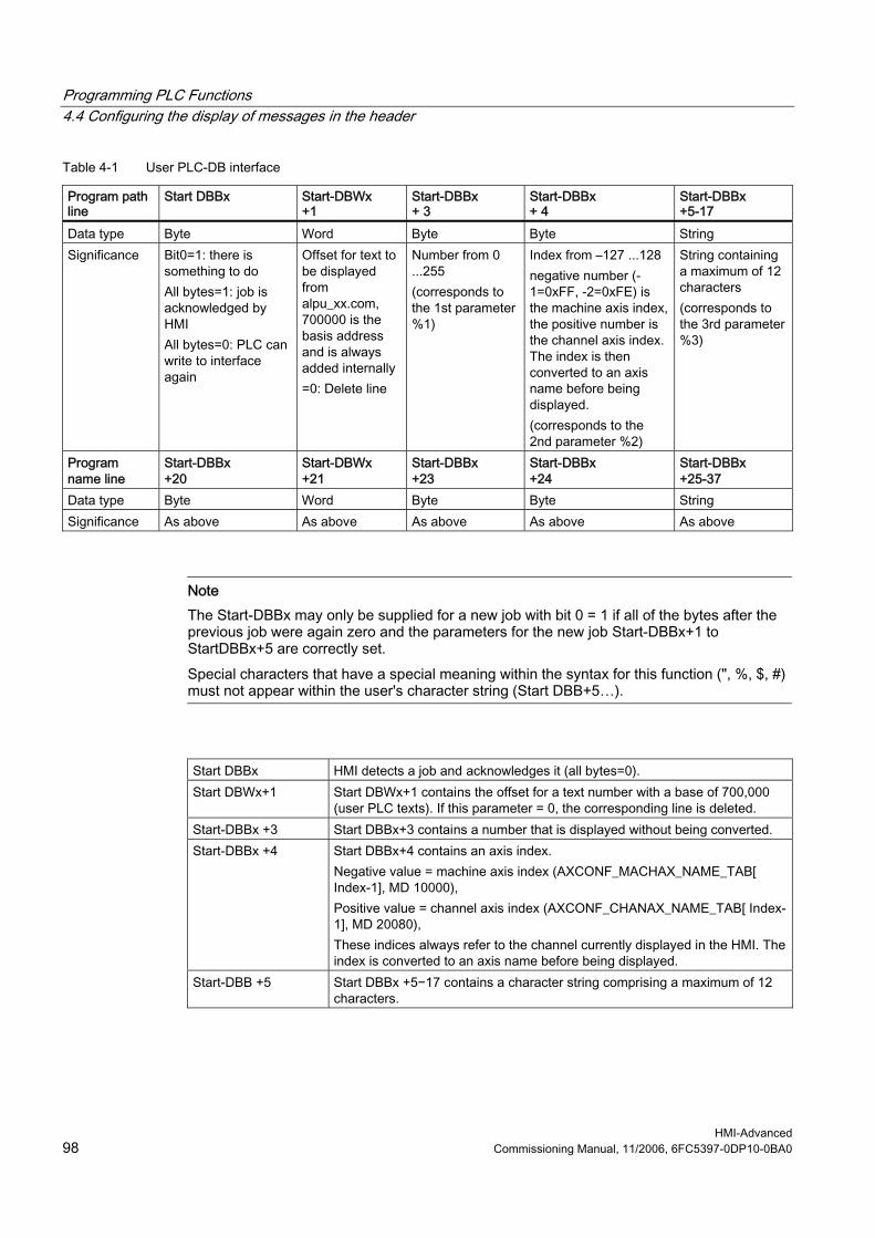
Programming PLC Functions 4.4 Configuring the display of messages in the header
HMI-Advanced 98 Commissioning Manual, 11/2006, 6FC5397-0DP10-0BA0
Table 4-1 User PLC-DB interface
Program path line
Start DBBx Start-DBWx +1
Start-DBBx + 3
Start-DBBx + 4
Start-DBBx +5-17
Data type Byte Word Byte Byte String Significance Bit0=1: there is
something to do All bytes=1: job is acknowledged by HMI All bytes=0: PLC can write to interface again
Offset for text to be displayed from alpu_xx.com, 700000 is the basis address and is always added internally =0: Delete line
Number from 0 ...255 (corresponds to the 1st parameter %1)
Index from –127 ...128 negative number (-1=0xFF, -2=0xFE) is the machine axis index, the positive number is the channel axis index. The index is then converted to an axis name before being displayed. (corresponds to the 2nd parameter %2)
String containing a maximum of 12 characters (corresponds to the 3rd parameter %3)
Program name line
Start-DBBx +20
Start-DBWx +21
Start-DBBx +23
Start-DBBx +24
Start-DBBx +25-37
Data type Byte Word Byte Byte String Significance As above As above As above As above As above
Note The Start-DBBx may only be supplied for a new job with bit 0 = 1 if all of the bytes after the previous job were again zero and the parameters for the new job Start-DBBx+1 to StartDBBx+5 are correctly set. Special characters that have a special meaning within the syntax for this function (", %, $, #) must not appear within the user's character string (Start DBB+5…).
Start DBBx HMI detects a job and acknowledges it (all bytes=0). Start DBWx+1 Start DBWx+1 contains the offset for a text number with a base of 700,000
(user PLC texts). If this parameter = 0, the corresponding line is deleted. Start-DBBx +3 Start DBBx+3 contains a number that is displayed without being converted. Start-DBBx +4 Start DBBx+4 contains an axis index.
Negative value = machine axis index (AXCONF_MACHAX_NAME_TAB[ Index-1], MD 10000), Positive value = channel axis index (AXCONF_CHANAX_NAME_TAB[ Index-1], MD 20080), These indices always refer to the channel currently displayed in the HMI. The index is converted to an axis name before being displayed.
Start-DBB +5 Start DBBx +5−17 contains a character string comprising a maximum of 12 characters.
Programming PLC Functions 4.4 Configuring the display of messages in the header
HMI-Advanced Commissioning Manual, 11/2006, 6FC5397-0DP10-0BA0 99
Structure of PLC program The PLC program must be laid out in such a way that all parameters are initialized before the first byte is set. The data for the program name line (second line) are located 20 bytes after the start byte.
Acknowledgement mechanism between HMI ↔ PLC For the Start DBBx, there is an acknowledgment mechanism that ensures that the HMI and PLC are coordinated: The PLC sets Bit 0 to 1 "Display user text in header". The function request can only be set by the PLC if Bit 0 has the value zero. After displaying the text in the header, the HMI writes zero again in bit 0 and the interface is enabled for the PLC for the next action.
Behavior for M: N (only SINUMERIK powerline) For the function M : N, both text lines for passive switching must be deleted. In active switching, as in area switching, the content of the variables is evaluated and displayed. Task: In the header of the JOG and MDA modes, the text "Handwheel acts on axis..." should be output in the field "Program name" in the first line together with the appropriate axis names; the text "slides ... active" should be output with the corresponding slide number in the second line. Procedure: 1. Identify the PLC ↔ HMI interface in the HEADER.INI file, e.g. DB60.DBB10 2. Enter name of the PLC user text file in MBDDE.INI, e.g.:
[TextFiles] UserPLC=alpu_
3. Enter texts in PLC user text file, e.g.: 700100 0 0 "Handwheel acts on axis %2" 700101 0 0 "Slides %1 active"
4. Initiate text display from the PLC and describe the interface, e.g. for the first display line: DB60.DBW11 = 100 DB60.DBB14 = 2 DB60.DBB10 = 1 e.g. for the second display line: DB60.DBW31 = 101 DB60.DBB33 = 1 DB60.DBB30 = 1
Programming PLC Functions 4.5 Starting a block search across several channels
HMI-Advanced 100 Commissioning Manual, 11/2006, 6FC5397-0DP10-0BA0
Result For an assumed axis configuration of MD 20080 AXCONF_CHANAX_NAME_TAB[0] = "X" MD 20080 AXCONF_CHANAX_NAME_TAB[1] = "Y" MD 20080 AXCONF_CHANAX_NAME_TAB[2] = "Z" the display is then as follows: "Handwheel acting on Y axis" (first display line) "Slide 1 active" (second display line)
4.5 Starting a block search across several channels
Function For this block search, the NCK is operated in the program test mode, so that interactions between channel and synchronous actions and between multiple channels are possible within an NCK. During the "Block search in the program test mode" the NCK outputs all help (auxiliary) functions to the PLC and the part program commands to coordinate the channels (WAITE, WAITM, WAITMC, axis exchange, writing to variables) are executed by the NCK; this means that during this block search, the PLC is brought up-to-date and processing sequences - that comprise the interaction of several channels - are correctly executed within the scope of this block search.
Activating the block search The function is activated by the "Prog. test contour" softkey. The NCK then starts the block search and switches the selected program in the current channel to "program test" mode: • The auxiliary functions of the part program are output from the NCK to the PLC. • No axis movements are executed. If during the block search the NC finds one of the part program commands WAITE, WAITC or WAITMC, the NCK waits for the specified partner channels, irrespective of the current mode of these partner channels (e.g. normal program execution, program test, search via program test, etc.). When the NC reaches the specified target block in the current channel, the NC stops the block search and deselects "program test" mode; the auxiliary functions of the target block are no longer output. A dialog message is output, which must be acknowledged as soon as all the channels involved in the current search have exited "program test" mode. The message indicates that, depending on the particular part program, REPOS offsets may have been produced during the search operation in the channels involved in the block search and will be retracted by the NC through interpolation the next time it starts. Any REPOS offsets can be approached manually one by one in JOG mode, before program execution is continued at the point in the program reached by the block search by pressing the "NC Start" key.
Programming PLC Functions 4.5 Starting a block search across several channels
HMI-Advanced Commissioning Manual, 11/2006, 6FC5397-0DP10-0BA0 101
Block search configurations Block search in "program test" mode supports the following configurations: 1. Block search in the currently selected channel (the currently selected channel is the
channel selected by the HMI). 2. Block search in the currently selected channel and in all channels in which the same
workpiece is selected as in the current channel. 3. Block search in the currently selected channel and in all channels that are in the same
mode group as the current channel. 4. Block search in all channels of the NCK Configurations 2 to 4: No block search is performed in the other channels (in contrast to the current channel); "program test" mode is active in the other channels until a stop condition (e.g. WAITMC) is detected.
Setting the search configuration The various configurations are activated in the MACHINE.INI file. The following settings are possible: [BlockSearch] SeruproEnabled=1 ; Shows (SeruproEnabled=1) or hides (SeruproEnabled=0) the softkey used to do a block search in "program test" mode. The softkey appears in both dialogs "Blocksearch Searchposition" and "Blocksearch Searchpointer" SeruproEnabled=0
=0 Function inactive
=1 Function active (default setting)
SeruproConfig=1
=1 Block search in currently selected channel (default setting)
=2 Block search in currently selected channel and in all channels with the same workpiece
=3 Block search in currently selected channel and in all channels with the same mode group
=4 Block search in all channels
Changes take effect immediately, i.e., with the next search.
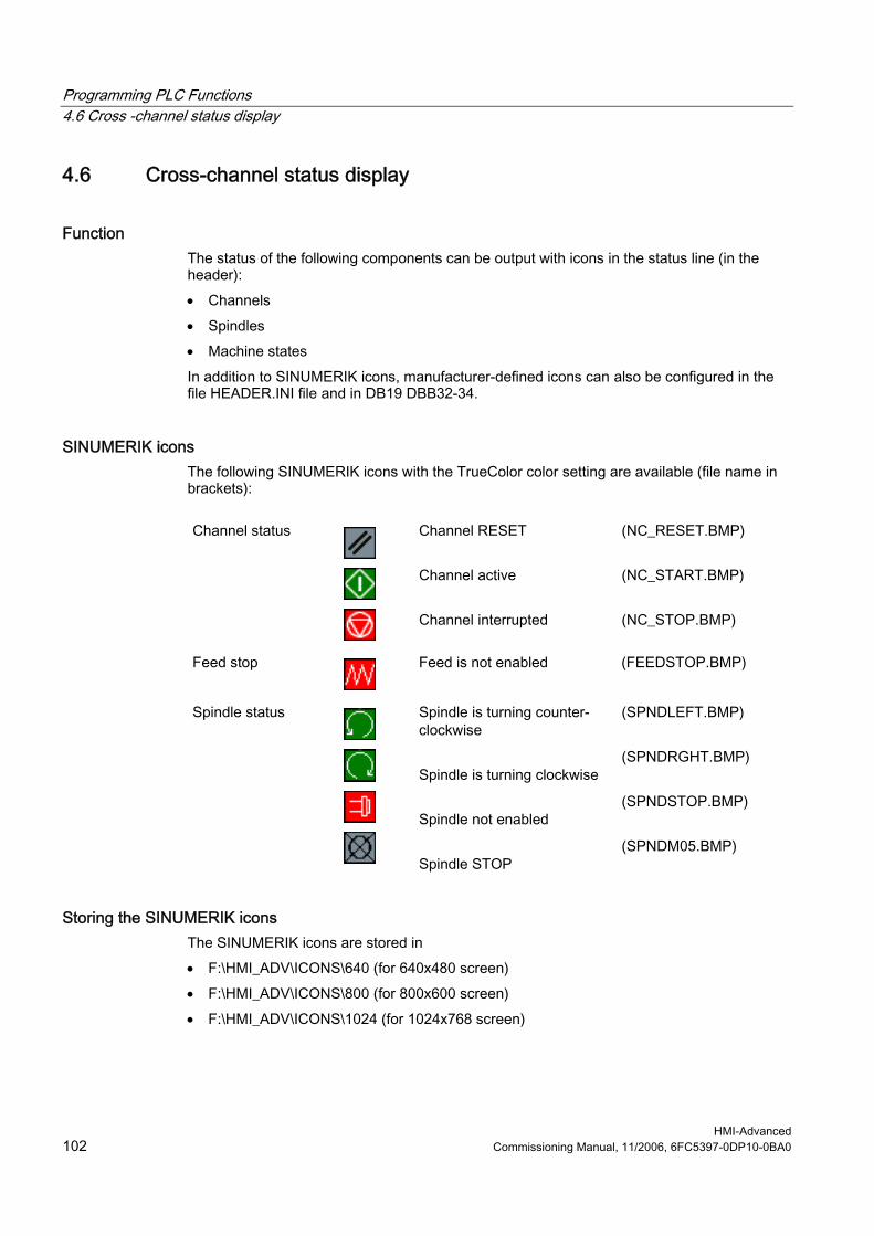
Programming PLC Functions 4.6 Cross -channel status display
HMI-Advanced 102 Commissioning Manual, 11/2006, 6FC5397-0DP10-0BA0
4.6 Cross-channel status display
Function The status of the following components can be output with icons in the status line (in the header): • Channels • Spindles • Machine states In addition to SINUMERIK icons, manufacturer-defined icons can also be configured in the file HEADER.INI file and in DB19 DBB32-34.
SINUMERIK icons The following SINUMERIK icons with the TrueColor color setting are available (file name in brackets):
Channel status
Channel RESET Channel active Channel interrupted
(NC_RESET.BMP) (NC_START.BMP) (NC_STOP.BMP)
Feed stop
Feed is not enabled (FEEDSTOP.BMP)
Spindle status
Spindle is turning counter-clockwise Spindle is turning clockwise Spindle not enabled Spindle STOP
(SPNDLEFT.BMP) (SPNDRGHT.BMP) (SPNDSTOP.BMP) (SPNDM05.BMP)
Storing the SINUMERIK icons The SINUMERIK icons are stored in • F:\HMI_ADV\ICONS\640 (for 640x480 screen) • F:\HMI_ADV\ICONS\800 (for 800x600 screen) • F:\HMI_ADV\ICONS\1024 (for 1024x768 screen)
Programming PLC Functions 4.6 Cross -channel status display
HMI-Advanced Commissioning Manual, 11/2006, 6FC5397-0DP10-0BA0 103
The dimensions of the SINUMERIK icons are as follows: • Resolution 640x480: 16x16 pixels • Resolution 800x600: 20x20 pixels • Resolution 1024x768: 27x26 pixels
Note When using the "Reversible spindles" or "Axis container" functions, the spindle status is output before the spindle reversal or assignment to axis/spindle container, i.e. the spindle number displayed under spindle status is the "logical" spindle.
Activating The function is activated by MD 9052 SHOW_CHANNEL_SPANNING_STATE > 0. Changes in MD 9052 take effect after a POWER ON. This function is available if it is activated by means of the following machine data element:
9052 SHOW_CHANNEL_SPANNING_STAT MD number Change cross-channel status display Default value: 0 Min. input value: 0 Max. input value: 1 Changes effective after POWER ON Protection level (R/W) 4/1 Units: - Data type: STRING Applies from SW version:
6.2
Significance Cross-channel status display: 0 = Display previous program status in header 1 = Display in program status line in header according to configuration in Header.ini file.
SINUMERIK status display The following 4 predefined displays are available:
1 Channel status (active, stopped, RESET) with superimposed spindle stop and feed
stop 2 Channel status (active, stopped, RESET) with superimposed feed stop 3 Channel status (active, stopped, RESET) 4 Spindle status Counter-clockwise direction, clockwise direction, spindle stop, spindle
halt M05
1 channel status The channel status, feed stop, and spindle status are output as an icon at the display position. The channel status icons can be superimposed with the "Spindle not enabled" or "Feed not enabled" icon.
Programming PLC Functions 4.6 Cross -channel status display
HMI-Advanced 104 Commissioning Manual, 11/2006, 6FC5397-0DP10-0BA0
The following hierarchy applies (from highest to lowest priority): 1. Channel STOP (highest priority) 2. Spindle not enabled 3. Feed is not enabled 4. Channel active 5. Channel RESET (lowest priority) Syntax: ChanStatFeedStopSpindleStop = <Channel number> Spindles = <Spindle number1>,...,<Spindle number n> Channel number: Number of channel Spindle number: Numbers of the "logical" spindles to be taken into consideration (programmed in the DIN code with S1 to Sn; if more than one applicable entry, the higher number is displayed).
2 channel status The channel status and spindle status are output as an icon at the display position (spindle status can be separately output). The channel status icons can be superimposed with the "Feed not enabled" icon. The following hierarchy applies (from highest to lowest priority): 1. Channel STOP (highest priority) 2. Feed is not enabled 3. Channel active 4. Channel RESET (lowest priority) Syntax: ChanStatFeedStop = <Channel number> Channel number: Number of channel
3 channel status The channel status is output as an icon at the display position. Feed stop is also output in the feed window in the Machine operating area, for example. Syntax: ChanStat = <Channel number> Channel number: Number of channel
4 spindle status The spindle status is output as an icon at the display position. Syntax: SpindStat = <Spindle number> , Chan <Channel number> Spindle number: Number of (logical) spindle Channel number: Number of channel optional

Programming PLC Functions 4.6 Cross -channel status display
HMI-Advanced Commissioning Manual, 11/2006, 6FC5397-0DP10-0BA0 105
If the channel number is not specified, then the spindle status for the current channel is displayed. If the channel is changed, the display is updated accordingly.
Configuring in the HEADER.INI The assignment of the cross-channel status display is defined in the HEADER.INI file. It can optionally be configured with SINUMERIK and user icons.
Note Empty positions need not be specified. Predefined status displays can be disabled in the HEADER.INI file in the OEM or USER directories with the value <empty>, e.g. ChanStatFeedStopSpindleStop = <empty>. The cross-channel status display and the use of the USER/OEM icons are mutually exclusive; i.e. either "cross-channel status display" or "USER/OEM icons" can be configured. (from ERLde78604) The complete file is provided in Chapter HEADER.INI.
Example with 16 display positions: There are 16 display positions defined in the program status line (header), where each SINUMERIK icon occupies two positions: number + icon.
Figure 4-1 Program status line with 16 positions
The SINUMERIK icons are permanently assigned to an output position. A section is created in the HEADER.INI configuration file for each position used. Example 1 with SINUMERIK icons: View of the program status line with SINUMERIK icons for 4 channels and 2 spindles:
Figure 4-2 Program status line with icons (1)
These displays always have the predefined channel or spindle number. Example 2 with SINUMERIK icons: The status displays for 2 channels and 1 spindle should always be output at the first, third and fifth display position.

Programming PLC Functions 4.6 Cross -channel status display
HMI-Advanced 106 Commissioning Manual, 11/2006, 6FC5397-0DP10-0BA0
HEADER.INI file:
[Pos1] ; first display position ChanStatFeedStopSpindleStop = 3 Spindles = 1,2 ; Channel status of channel 3 is
displayed, superimposed with feed inhibit channel 3 and spindle inhibit for spindles1 and 2
[Pos3] ; third display position ChanStatFeedStop = 2 ; Channel status of channel 2 is
displayed superimposed with the feed inhibit, channel 2
[Pos5] ; fifth display position SpindStat= 3 ; spindle status for spindle 3 is
displayed The following display, for example, appears in the program status line:
Figure 4-3 Program status line with icons (2)
Deactivating Icon displays configured in this way can be deactivated if user status displays are used as described in B. Create empty entries in a user-specific HEADER.INI file (not in the hmi_adv directory, because this would be overwritten again when the software is upgraded). Example: [Pos5] SpindStat=<EMPTY>
See also HEADER.INI (Page 152)
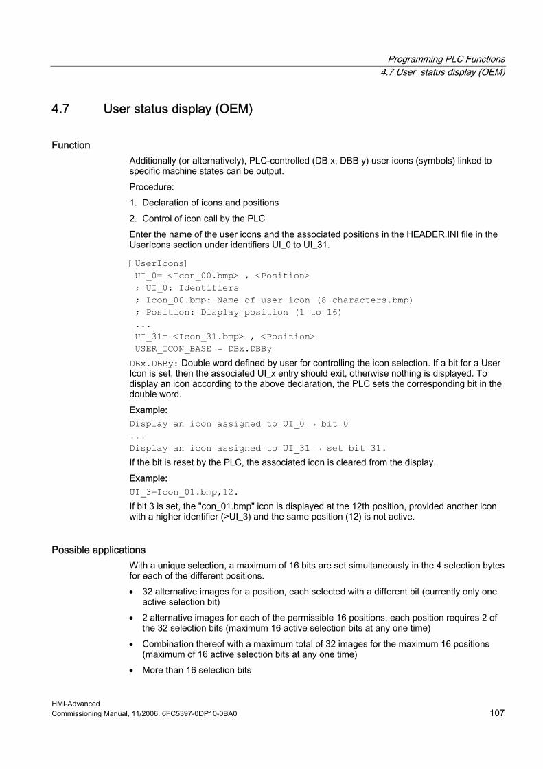
Programming PLC Functions 4.7 User status display (OEM)
HMI-Advanced Commissioning Manual, 11/2006, 6FC5397-0DP10-0BA0 107
4.7 User status display (OEM)
Function Additionally (or alternatively), PLC-controlled (DB x, DBB y) user icons (symbols) linked to specific machine states can be output. Procedure: 1. Declaration of icons and positions 2. Control of icon call by the PLC Enter the name of the user icons and the associated positions in the HEADER.INI file in the UserIcons section under identifiers UI_0 to UI_31. [UserIcons] UI_0= <Icon_00.bmp> , <Position> ; UI_0: Identifiers ; Icon_00.bmp: Name of user icon (8 characters.bmp) ; Position: Display position (1 to 16) ... UI_31= <Icon_31.bmp> , <Position> USER_ICON_BASE = DBx.DBBy DBx.DBBy: Double word defined by user for controlling the icon selection. If a bit for a User Icon is set, then the associated UI_x entry should exit, otherwise nothing is displayed. To display an icon according to the above declaration, the PLC sets the corresponding bit in the double word. Example: Display an icon assigned to UI_0 → bit 0 ... Display an icon assigned to UI_31 → set bit 31. If the bit is reset by the PLC, the associated icon is cleared from the display. Example: UI_3=Icon_01.bmp,12. If bit 3 is set, the "con_01.bmp" icon is displayed at the 12th position, provided another icon with a higher identifier (>UI_3) and the same position (12) is not active.
Possible applications With a unique selection, a maximum of 16 bits are set simultaneously in the 4 selection bytes for each of the different positions. • 32 alternative images for a position, each selected with a different bit (currently only one
active selection bit) • 2 alternative images for each of the permissible 16 positions, each position requires 2 of
the 32 selection bits (maximum 16 active selection bits at any one time) • Combination thereof with a maximum total of 32 images for the maximum 16 positions
(maximum of 16 active selection bits at any one time) • More than 16 selection bits
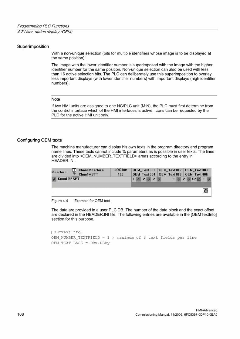
Programming PLC Functions 4.7 User status display (OEM)
HMI-Advanced 108 Commissioning Manual, 11/2006, 6FC5397-0DP10-0BA0
Superimposition With a non-unique selection (bits for multiple identifiers whose image is to be displayed at the same position): The image with the lower identifier number is superimposed with the image with the higher identifier number for the same position. Non-unique selection can also be used with less than 16 active selection bits. The PLC can deliberately use this superimposition to overlay less important displays (with lower identifier numbers) with important displays (high identifier numbers).
Note If two HMI units are assigned to one NC/PLC unit (M:N), the PLC must first determine from the control interface which of the HMI interfaces is active. Icons can be requested by the PLC for the active HMI unit only.
Configuring OEM texts The machine manufacturer can display his own texts in the program directory and program name lines. These texts cannot include % parameters as is possible in user texts. The lines are divided into <OEM_NUMBER_TEXTFIELD> areas according to the entry in HEADER.INI.
Figure 4-4 Example for OEM text
The data are provided in a user PLC DB. The number of the data block and the exact offset are declared in the HEADER.INI file. The following entries are available in the [OEMTextInfo] section for this purpose. [OEMTextInfo] OEM_NUMBER_TEXTFIELD = 1 ; maximum of 3 text fields per line OEM_TEXT_BASE = DBx.DBBy

Programming PLC Functions 4.7 User status display (OEM)
HMI-Advanced Commissioning Manual, 11/2006, 6FC5397-0DP10-0BA0 109
The interface in the user DB has the following format:
Start-DBB byte or Start-DBB +18 byte
Bit0=1: there is something to do All bits=1: job is acknowledged by HMI All bits=0: PLC can write to interface again.
Start-DBB +1 word or Start-DBB +19 word
Offset for text from alpu_xx.com to be displayed; 700 000 is the base address and is always summed internally. All bits=0: Delete line
Start-DBB + 3 string or Start DBB+20 double Word
String containing a maximum of 12 characters
The first parameter contains an offset for a text number with a base of 700,000 (user PLC texts). If this parameter = 0, the corresponding line is deleted. The second parameter contains a maximum 12-character string. Unless empty, this text is output instead of the user PLC text. The parameters must be written from "back to front" in the PLC, i.e., all parameters must be initialized before the first byte is set. The data for the next line are located exactly 18 bytes after the start byte. The lines are output from left to right; a maximum of three output fields per line are provided (i.e., a total of 6 fields are possible). A hotlink to the first byte for each line is set up in the HMI. If a change occurs in that byte, the HMI reacts. If the HMI has displayed the data, it writes a –1 to the first variable. The HMI is informed about this change by means of the hot link, whereupon it writes a 0 to this variable. The HMI itself does not have to react to this change. The PLC can only write data to the interface again if the variable is set to 0. This mechanism ensures that the HMI knows about all parameter changes.
Configuring OEM icons OEM icons indicating the machine state can be output in the field provided for the program control display (e.g. SBL, M01, etc.). If OEM icons are defined, the elements for the program control display are hidden. The icon names are identified in the HEADER.INI configuration file, same as the user icons. [OemIcons] OI_0= <name.bmp>, <Position> ... OI_31= <name.bmp>, <Position> Here, <name> is the file name of the bit map and <Position> is the output position (from 1 to 16) in the display line. Multiple bit maps can be output at the same position. If more than one bit map is active simultaneously at the same position, the bit map with the highest screen number is displayed.

Programming PLC Functions 4.7 User status display (OEM)
HMI-Advanced 110 Commissioning Manual, 11/2006, 6FC5397-0DP10-0BA0
The output is controlled by means of a PLC double word. This double word is declared in the next section in the HEADER.INI file: [OemIcons] Oem_ICON_BASE = DBx.DBBy Each bit in this double word represents exactly one OEM icon corresponding to the screen number. Thus, if bit 0 is set, bit map OI_0 is displayed. If a bit is reset, the associated bit map is deleted. A maximum of 16 icons can be displayed, enabling a total of 16 display positions. Empty positions need not be specified.
Figure 4-5 Example for OEM Icons
See also HEADER.INI (Page 152)
HMI-Advanced Commissioning Manual, 11/2006, 6FC5397-0DP10-0BA0 111
Diagnostics and service 55.1 Installing HMI software on a PG/PC
Requirements
Target system: PG or PC with 600 MHz / 256 MB RAM Available hard disk space: 500 MB
Operating system: Windows XP Professional MPI driver: Version 6 NC connection (SINUMERIK powerline) CP5511
CP5611 NC connection (SINUMERIK solution line): Network connection (Ethernet)
"Small fonts" must be selected under "Control Panel → Display, Settings".
Software
• Name HMI-Advanced for PC/PG • Installation language German/English • Distribution medium CD • Can be uninstalled Yes
Operating sequence 1. Insert the CD in the CD drive 2. Start setup.exe 3. Select language 4. Specify the target directory: Any 5. For SINUMERIK powerline, select:
– Online with communication to NC – The system asks whether you wish to install the MPI drivers – Local without communication to NC, with NC simulation

Diagnostics and service 5.1 Installing HMI software on a PG/PC
HMI-Advanced 112 Commissioning Manual, 11/2006, 6FC5397-0DP10-0BA0
6. For SINUMERIK solution line, select: – Online with communication to NC
7. The system lists all the entries you have made 8. On confirmation the copy operation starts 9. At the end of the copying operation, you are prompted to restart the PC.
Note Installing on a PC/PG: HMI-Advanced can then only be run under a non-administrator user, if this user has write privileges for directory mmc2 of HMI-Advanced. The installation of HMI-Advanced does not provide these privileges.
5.1.1 NCU Connection Wizard
Use The NCU Connection Wizard is only installed during the installation of HMI-Advanced on a PG/PC. This assists you during the commissioning of the NCK, PLC and drive and during the configuration of interfaces and the cabling. With the Connection Wizards, connections are possible both via MPI and Ethernet, depending on the control unit. Use an Ethernet connection for SINUMERIK solution line and an MPI connection for SINUMERIK powerline. The type of connection depends on the software installed on the 840Di control unit.
Starting the "NCU Connection Wizard" The Connection Wizard is started under "Start menu" → "NCU Connection Wizard" or it is automatically started after a message if no connection to the control unit can be established.
Note Changes that you made using the "NCU Connection Wizard" only take effect after a system restart.

Diagnostics and service 5.1 Installing HMI software on a PG/PC
HMI-Advanced Commissioning Manual, 11/2006, 6FC5397-0DP10-0BA0 113
5.1.2 Starting HMI-Advanced in a separate desktop
Overview Installing HMI-Advanced on a standard PC creates boundary conditions which cause the following effects when other programs are used: • Windows that cannot be moved or minimized • Special keyboard and keyboard filter functions • Overcrowded task bar • Changes to color scheme • Focus control in connection with OEM software • All applications of a standard PC run under one desktop. How to call-up HMI-Advanced in a separate desktop as remedy is described in the following section.
Remedy Through the dynamic creation of a separate desktop for the HMI-Advanced software, the features indicated above are limited to this desktop. In addition, up to three desktops can be defined without these restrictions. Various methods can be used to switch between the desktop with HMI-Advanced and the other desktops at any time. Desktop creation is configurable. The solution is only available for PGs/PCs, not for PCU 50.3. Desktop applications: • In addition to a standard desktop that is always present, one or more desktops are
created dynamically. • HMI-Advanced is loaded into a dynamically created, standalone desktop. • All existing desktops are provided with a user interface that allows switching to another
desktop at any time. • The desktop can be configured using the HMIDesk.ini file.

Diagnostics and service 5.1 Installing HMI software on a PG/PC
HMI-Advanced 114 Commissioning Manual, 11/2006, 6FC5397-0DP10-0BA0
Figure 5-1 Separate desktops for HMI-Advanced and other applications
Note 1. The key combination CTRL+ALT+DEL of the task manager only works in the standard
desktop. In dynamic desktops, the task manager can only be called directly from the task bar.
2. When a dynamic desktop is closed, the application that is started automatically by inclusion in hmidesk.ini is closed with the desktop. Additional, manually started applications continue to run, however. The applications can no longer be used, however, since they are not displayed in other desktops. If the dynamic desktop is started again later, applications that are still running are visible again and can continue to be used.
3. All external applications (e.g. ProTool, TRANSLINE) that use the basic HMI-Advanced system must be started on the HMI desktop if they are to be executed in parallel with HMI-Advanced. Background: The sequence control subsystems cannot be used beyond desktop limits because Windows restricts window communications to one desktop.
4. 16-bit applications are always started by Windows in the login desktop and so do not work in a dynamic HMI desktop. The desktop switch can therefore not be used if 16-bit applications are being used in HMI-Advanced. In this case, HMI-Advanced must be started in the conventional way.
Diagnostics and service 5.1 Installing HMI software on a PG/PC
HMI-Advanced Commissioning Manual, 11/2006, 6FC5397-0DP10-0BA0 115
5.1.3 Configuring the desktop switch application
Function The application is configured in the HMIDESK.INI, in the section [Global]. Under[Global], the required number of desktops is specified with NumberOfDesktops = n. The 2nd to 4th desktops are created dynamically. Permissible values for n are 2, 3, 4. For each dynamic desktop, additional settings must be specified in [Desktopn].
ControlMode = Icon Icons in the task bar (Explorer below) Window Standalone dialog window
(WindowOnTop below) KeyboardControl = TRUE Switching can be done using <ALT+1>,
<ALT+2>, ... dialog window or task bar. FALSE Switching can be done using the dialog window
or task bar. [Desktop n] section StartupApplication = "Path\Program.exe" An application is started automatically after creating a desktop: On closing the desktop, this application is closed by the desktop switch. Closing of the desktop is synchronized with the closing of the application. During this synchronization, the desktop switch cannot process any other requests. The synchronization is aborted if the application is still being executed after 15 seconds. In this case, the desktop is closed too.
Note For the desktop (2), the path and associated program name pointing to the current HMI-Advanced installation are set automatically.
Explorer = TRUE Desktop is provided with Explorer and a task bar
which contains the icons for the configured desktops.
FALSE Desktop is not provided with Explorer or a task bar The desktop can only be selected via the keyboard <ALT+1>, <ALT+2>, ... or via the dialog window.
WindowOnTop = TRUE If ControlMode = Window is present, the dialog window of the desktop switch application is constantly displayed.
FALSE Dialog window can be covered CreateDesktop = Immediately Start desktop immediately. Delayed Start desktop when selected.

Diagnostics and service 5.1 Installing HMI software on a PG/PC
HMI-Advanced 116 Commissioning Manual, 11/2006, 6FC5397-0DP10-0BA0
SetHMIColors = TRUE With SetHMIColors, the Desktop 2 uses its own color scheme with the advantage that this color scheme does not affect other desktops. This attribute is intended exclusively for use with HMI-Advanced, because it uses its own color scheme which is partially very different from standard Windows.
FALSE The desktops are displayed with the standard Windows color scheme, as is the desktop with HMI-Advanced.
When switching between desktops, the desktop switch sets the appropriate color scheme automatically. Desktop 1 is the user's standard desktop, which is set up automatically by the operating system after logon. For the standard desktop, only the property WindowsOnTop = True can be configured. • Activating
Start HMIDesk.exe in the installation directory for HMI-Advanced. The configured desktops are created. HMI-Advanced is started automatically in desktop 2 as the startup application.
• Behavior when creating a desktop An active desktop is created with the task bar. The desktop switch window is hidden. The desktop switch is operated via the task bar.
5.1.4 Operating the desktop switch application
Overview The user interface for the desktop switch application can be configured: • Keyboard hotkeys • Dialog window • Icons in the task bar Hotkeys:
<Alt+1> Switches to desktop 1 (standard user desktop) <Alt+2> Switches to desktop 2 (HMI-Advanced desktop) <Alt+3> Switches to desktop 3 (optional additional user desktop) <Alt+4> Switches to desktop 4 (optional additional user desktop)

Diagnostics and service 5.1 Installing HMI software on a PG/PC
HMI-Advanced Commissioning Manual, 11/2006, 6FC5397-0DP10-0BA0 117
Starting HMI_Advanced in a separate desktop: 1. First start a second desktop, then HMI-Advanced:
Figure 5-2 Linking to the desktop switching application
2. Switching by clicking on the corresponding desktop number:
1 Standard desktop 2 Desktop with HMI-Advanced (3, 4) Other optional desktops
↑ Displaying the desktop ↑ Changing over the active desktop
Note If WindowOnTop = False is configured in HMIDESK.INI, the window must be brought to the foreground using <Alt + TAB>.

Diagnostics and service 5.2 Displaying versions
HMI-Advanced 118 Commissioning Manual, 11/2006, 6FC5397-0DP10-0BA0
5.2 Displaying versions
Overview The version data displayed under “NCU Version” state the software versions on the CF card. This especially applies to measurement cycles and cycle versions. • Version data, NCU • Version data, HMI files • Version data, cycles • Version data, definitions The measurement cycles and cycles that are used by HMI-Advanced are available on the hard disk of the PCU. Their version can be queried via the horizontal softkeys. With the “Detail” softkey, you can query further information about a version, for example, to pass it on to hotline support personnel if service is required.
Figure 5-3 NCU version (example)
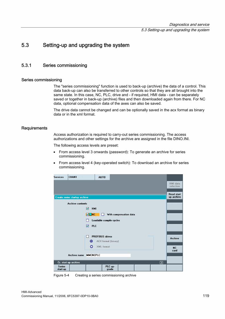
Diagnostics and service 5.3 Setting-up and upgrading the system
HMI-Advanced Commissioning Manual, 11/2006, 6FC5397-0DP10-0BA0 119
5.3 Setting-up and upgrading the system
5.3.1 Series commissioning
Series commissioning The "series commissioning" function is used to back-up (archive) the data of a control. This data back-up can also be transferred to other controls so that they are all brought into the same state. In this case, NC, PLC, drive and - if required, HMI data - can be separately saved or together in back-up (archive) files and then downloaded again from there. For NC data, optional compensation data of the axes can also be saved. The drive data cannot be changed and can be optionally saved in the acx format as binary data or in the xml format.
Requirements Access authorization is required to carry-out series commissioning. The access authorizations and other settings for the archive are assigned in the file DINO.INI. The following access levels are preset: • From access level 3 onwards (password): To generate an archive for series
commissioning. • From access level 4 (key-operated switch): To download an archive for series
commissioning.
Figure 5-4 Creating a series commissioning archive
Diagnostics and service 5.3 Setting-up and upgrading the system
HMI-Advanced 120 Commissioning Manual, 11/2006, 6FC5397-0DP10-0BA0
Creating an archive To create a commissioning archive: 1. In the operator area "Services" select "Series commissioning" on the expanded softkey
bar. 2. Select archive content.
If HMI data are selected for the archive: The F:USER directory is always backed up. – Keep the default setting with the standard values. – Select the required data using the softkey "HMI data selection". Directories \ADD_ON
and \OEM can be saved under "Additional products", either completely ("Complete") or just the INI files ("Configuration").
3. Archive name: Accept the recommendation given by the system or enter a name. 4. Start creating the archive using the softkey "Archive" or "NC card".
Ensure that there is sufficient free memory space. Result: When selecting "Archive", the archive is saved on the hard disk under the following path: F:\dh\arc.dir\ ...
Read-in archive Requirements: The commissioning archive must be located under the same path on the new control as on the control on which it was created. In order to read-in a commissioning archive: 1. Select the softkey "Read-in commissioning archive": The directory is displayed. 2. Start the read-in (download) operation using the softkey "Start". 3. Acknowledge the prompt with "Yes".
The archive is read-in (downloaded) and the system is automatically re-started in order that the archive data become effective.
Note Also when reading-in an archive, the available memory space must be at least the size of the series commissioning archive. If a control is configured for M:N, the PCU must be re-started after executing a series commissioning (start-up) so that the devices in the network (NCU, PLC, HMI) can re-synchronize.

Diagnostics and service 5.3 Setting-up and upgrading the system
HMI-Advanced Commissioning Manual, 11/2006, 6FC5397-0DP10-0BA0 121
For compile cycles (CC) that can be downloaded, the following specifically applies: The compile cycles that can be loaded are archived in the series commissioning under the following requirements: • In the commissioning archive, in the target directory ../NC_CARD.DIR/CCOEM.DIR, there
must be at least one compile cycle. • It is only possible to selectively archive individual compile cycles by copying to a USB
memory.
5.3.2 Upgrading the PLC
Requirements Access level 0-3 is required both to upgrade the PLC as well as to upgrade system data blocks (SDB).
Use When upgrading the PLC and/or system data blocks, only specific data can be updated by entering the blocks into an INI file that are not overwritten and should therefore be updated: • Upgrading the PLC
In order to upgrade the PLC, select "PLC" and create a PLC series commissioning archive. Further, enter the blocks into a separate INI fie that should not be updated.
• Upgrading system data blocks To upgrade the hardware, under "PLC", also select "PLC hardware upgrade (only SDB)". This means that the hardware configuration can be made without using STEP 7 and using the saved SDB upgrade archive. This option can only be selected if exclusively the "PLC" option is selected. The recommended archive name is SDB.ARC. All SDB of the actual PLC, which are in the RAM and active, are entered into this archive. SDB that are set-up by the CPU as default setting are not entered.
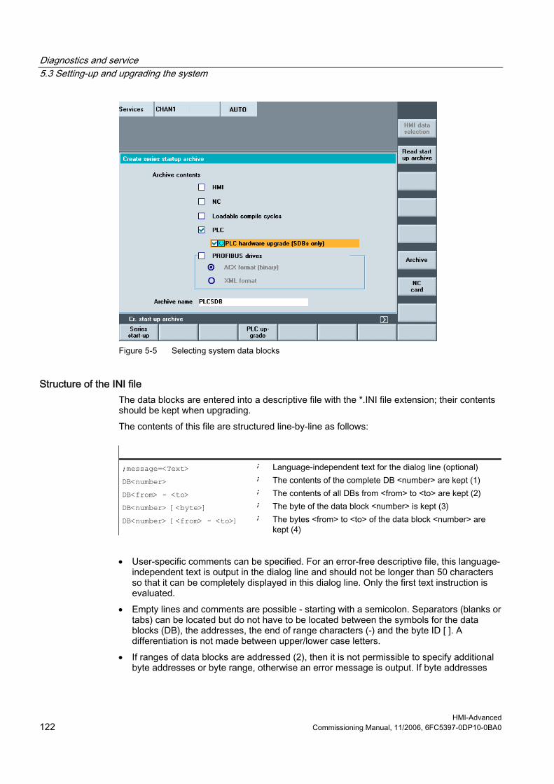
Diagnostics and service 5.3 Setting-up and upgrading the system
HMI-Advanced 122 Commissioning Manual, 11/2006, 6FC5397-0DP10-0BA0
Figure 5-5 Selecting system data blocks
Structure of the INI file The data blocks are entered into a descriptive file with the *.INI file extension; their contents should be kept when upgrading. The contents of this file are structured line-by-line as follows:
;message=<Text> ; Language-independent text for the dialog line (optional) DB<number> ; The contents of the complete DB <number> are kept (1) DB<from> - <to> ; The contents of all DBs from <from> to <to> are kept (2) DB<number> [<byte>] ; The byte of the data block <number> is kept (3) DB<number> [<from> - <to>] ; The bytes <from> to <to> of the data block <number> are
kept (4)
• User-specific comments can be specified. For an error-free descriptive file, this language-
independent text is output in the dialog line and should not be longer than 50 characters so that it can be completely displayed in this dialog line. Only the first text instruction is evaluated.
• Empty lines and comments are possible - starting with a semicolon. Separators (blanks or tabs) can be located but do not have to be located between the symbols for the data blocks (DB), the addresses, the end of range characters (-) and the byte ID [ ]. A differentiation is not made between upper/lower case letters.
• If ranges of data blocks are addressed (2), then it is not permissible to specify additional byte addresses or byte range, otherwise an error message is output. If byte addresses
Diagnostics and service 5.3 Setting-up and upgrading the system
HMI-Advanced Commissioning Manual, 11/2006, 6FC5397-0DP10-0BA0 123
are defined for a data block (3, 4), then for this data block there may be no entry without byte address (1, 2) otherwise an error is output.
• The instructions can be in any sequence.
Syntax check of the INI file The descriptive file with the *.INI file extension can be copied into the archive directory via a USB drive or network drive (option). When displaying the files under PLC upgrade, the syntax of the data contents is checked. If a syntax error is identified, the line number of the first syntax error is displayed in the dialog line. When opening the file, the cursor is located at the line with the error.
Upgrade sequence In order to upgrade the PLC, proceed as follows: • Before upgrading a complete PLC, create a series commissioning archive of the machine
to be upgraded; if an error occurs, the original state of the PLC will be able to be restored. • For the PLC upgrade, a complete PLC series commissioning archive is created as well as
a descriptive file, e.g. generated by the machine construction OEM. The archive and the descriptive file are downloaded into the archive directory of the machine to be upgraded. The target directory is mandatory.
• Select the INI file and a PLC series commissioning archive from which the archive directory is selected. A syntax check is subsequently started.
• Using the softkey "Start", data is read out of the archive into the PLC using the descriptive file. To do this, initially, a complete, temporary original PLC archive of the actual machine is generated. A complete temporary target PLC archive is generated from this archive using the selected upgrade archive and the descriptive file.The length of the data blocks is determined by the upgrade archive and the contents are determined by the descriptive file. The temporary target PLC archive is then downloaded and the two temporary archives are again deleted after the upgrade.
• If several machines with identical PLC status are to be upgraded, then from the first upgraded machine, a complete PLC archive can be generated and using this PLC archive, the remaining machines can be commissioned without requiring a descriptive file. Before upgrading using such an archive, the following prompt is output: Series commissioning archive: Upgrade hardware configuration PLC (SDBs) ?
Note The softkey "Start" is only effective if an archive and a descriptive file with the correct syntax are selected.

Diagnostics and service 5.3 Setting-up and upgrading the system
HMI-Advanced 124 Commissioning Manual, 11/2006, 6FC5397-0DP10-0BA0
5.3.3 Example: Upgrading the PLC
Procedure In the following example, data blocks DB3, DB67 and DB111 are not to be overwritten. 1. As back-up, create a series commissioning archive of the PLC data. 2. Create a descriptive file with the following contents:
;Message= designed by XXX (SIEMENS AG Erlangen) DB3[3-78] DB67 ; DB67 complete DB 3 [79] DB3[2] DB111 ; DB111 complete
3. Save the descriptive file as TEST1.INI and save in the directory ..\dh\arc.dir of the control that is to be upgraded.
4. Select the descriptive file TEST1.INI and the series commissioning archive to upgrade the control. The syntax is checked.
5. Press "Start": While copying, the text message is output from the INI file.
Figure 5-6 Start the PLC upgrade
Diagnostics and service 5.3 Setting-up and upgrading the system
HMI-Advanced Commissioning Manual, 11/2006, 6FC5397-0DP10-0BA0 125
Result All of the data blocks of the upgrade archive are transferred into the PLC for which no entry exists in the descriptive file: The PLC was upgraded to the current status without overwriting data blocks DB3, DB67 and DB111.
Rules For the data blocks listed in the descriptive file, the following behavior is defined when upgrading: • If the data block of the upgrade archive does not exist in the PLC, then an appropriate
entry is made in the error log. • The length of the data block is defined by the length in the upgrade archive. • If byte addresses are defined for the data block, then these data areas are transferred
from the upgrade archive into the PLC. Error messages are output if the address either does not exist in the upgrade archive or in the PLC.
• If no byte addresses are defined for the data block, then the contents of the PLC data block are kept. Where necessary, the data block is shortened to the new length.
• If the data block in the upgrade archive is longer than that in the PLC, then the remaining range is filled with the contents of the upgrade archive.
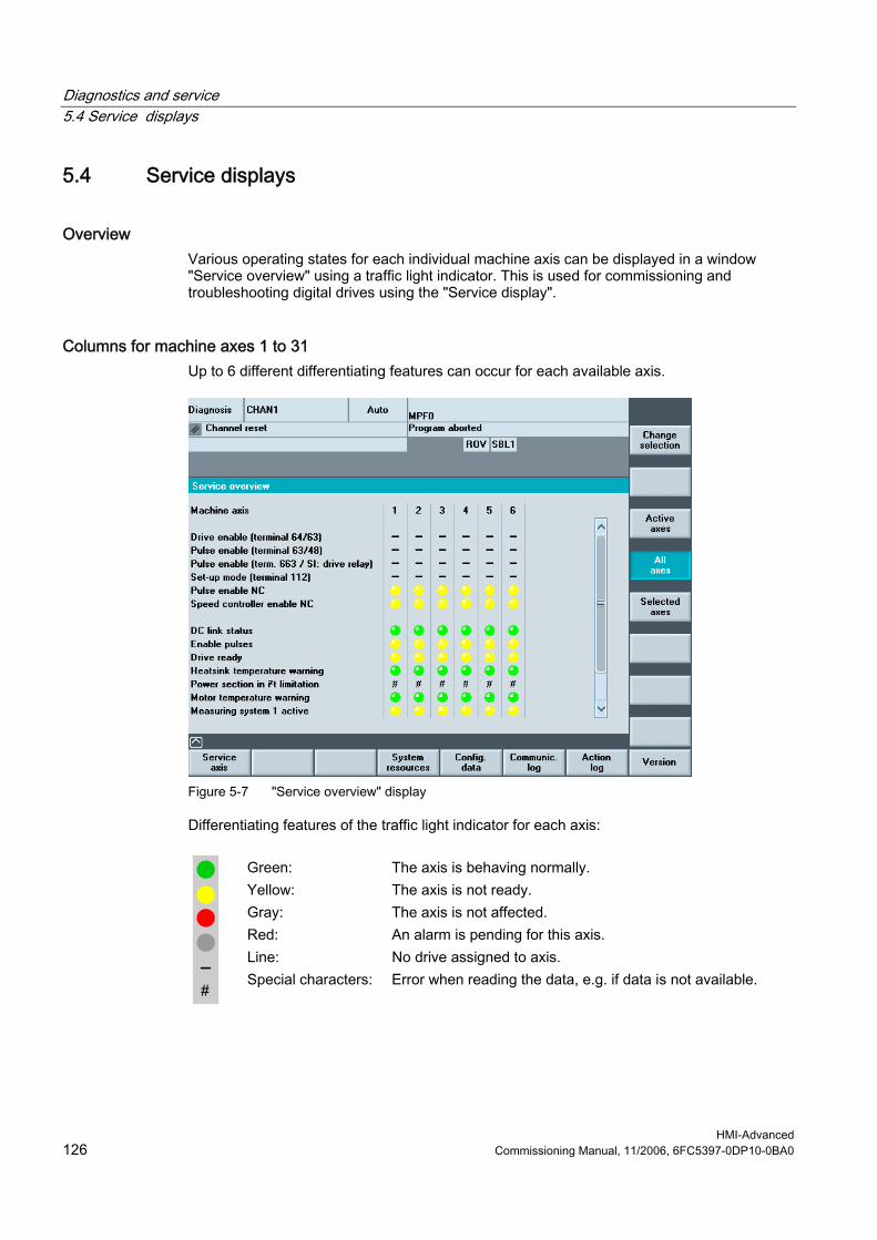
Diagnostics and service 5.4 Service displays
HMI-Advanced 126 Commissioning Manual, 11/2006, 6FC5397-0DP10-0BA0
5.4 Service displays
Overview Various operating states for each individual machine axis can be displayed in a window "Service overview" using a traffic light indicator. This is used for commissioning and troubleshooting digital drives using the "Service display".
Columns for machine axes 1 to 31 Up to 6 different differentiating features can occur for each available axis.
Figure 5-7 "Service overview" display
Differentiating features of the traffic light indicator for each axis:
Green: The axis is behaving normally. Yellow: The axis is not ready. Gray: The axis is not affected. Red: An alarm is pending for this axis. Line: No drive assigned to axis.
Special characters: Error when reading the data, e.g. if data is not available.
Diagnostics and service 5.4 Service displays
HMI-Advanced Commissioning Manual, 11/2006, 6FC5397-0DP10-0BA0 127
Selecting the axes Press the vertical softkey "Change selection...", to create a dedicated list of axes. The available axes can be entered in the axis list in any order. Example: 4 axes should appear in the order 1 3 5 8. Enter the newly selected axes, separated by a blank: 1 3 5 8 and acknowledge this using the key <Insert>. Axis numbers outside the valid range from 1 to 31 are deleted. If an attempt is made to enter an empty list, then the default setting is displayed.
Displaying selected axes The following axes are displayed in the window "Service overview":
"Active axes": The active axes presently identified "All axes": The maximum possible axes "Selected axes": The last generated axis selection
5.4.1 Service, axis/spindle
Use The information in the "Service axis" window is used to check: • Setpoint branch: e.g. position setpoint, speed setpoint, programmed spindle speed
setpoint • Actual value branch: e.g. position actual value measuring system 1 and 2, position
setpoint • Optimizing the position control loop of the axis: e.g. following error, system deviation, Kv
factor) • Complete control loop of the axis: e.g. by comparing the position setpoint and the position
actual value, speed setpoint and speed actual value • Hardware faults: e.g. checking the encoder. If the axis is moved mechanically, the actual
position value must change. • Setting and checking axis monitoring functions The "Service axis/spindle" window displays reference values and units for the machine axis together with axis name and axis number. The service values of the next or previous axis are displayed using the softkeys "Axis +" and "Axis −". The "Direct selection" softkey allows you to select an axis directly from the list of available axes.
Diagnostics and service 5.4 Service displays
HMI-Advanced 128 Commissioning Manual, 11/2006, 6FC5397-0DP10-0BA0
5.4.2 Displaying system resources
Function The system resources for the NCU are displayed in the window "NC utilization": • The net and overall runtime of the position controller, the interpolator and the pre-run in
milli-seconds • NCU load level as a percentage • Buffer filling level as a percentage The display update is stopped using the "Stop" softkey, the displayed values are updated again with the "Start" softkey.
5.4.3 Output of configuration data
Function The configuration data of a machine (HMI version, NCU version, axis configuration, drive configuration, bus parameters, active bus nodes) can be written into a file and subsequently read out or printed. Configuration data is output in 2 stages: • Creation of the configuration data file CONFIGURATION_DATA in the "Diagnostics"
operating area by pressing the "Config. data" softkey. • Read-out of the CONFIGURATION_DATA file in the “Services” operating area. To do
this, the configuration file CONFIGURATION_DATA is generated. Procedure: 1. Select the menu "Service displays". 2. The horizontal softkey bar changes 3. Press the "Config. data" softkey.
The system gathers the configuration data, writes it into the file CFGDAT.TXT and displays it. The path and name of the file are output in the info line.
5.4.4 Communication error log
Function Errors that occur during communication between the HMI and NCK/PLC are registered in a communication error log. You can display the errors by pressing this softkey. The error log file is principally used by the control manufacturer (Siemens) to diagnose communication errors.
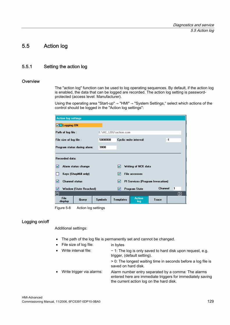
Diagnostics and service 5.5 Action log
HMI-Advanced Commissioning Manual, 11/2006, 6FC5397-0DP10-0BA0 129
5.5 Action log
5.5.1 Setting the action log
Overview The "action log" function can be used to log operating sequences. By default, if the action log is enabled, the data that can be logged are recorded. The action log setting is password-protected (access level: Manufacturer). Using the operating area "Start-up" → "HMI" → "System Settings,“ select which actions of the control should be logged in the "Action log settings":
Figure 5-8 Action log settings
Logging on/off Additional settings:
• The path of the log file is permanently set and cannot be changed. • File size of log file: in bytes • Write interval file: − 1: The log is only saved to hard disk upon request, e.g.
trigger, (default setting). > 0: The longest waiting time in seconds before a log file is saved on hard disk.
• Write trigger via alarms: Alarm number entry separated by a comma: The alarms entered here are immediate triggers for immediately saving the current action log on the hard disk.

Diagnostics and service 5.5 Action log
HMI-Advanced 130 Commissioning Manual, 11/2006, 6FC5397-0DP10-0BA0
Logged data The following data are logged:
• Alarm status change: Alarms and PLC messages, incoming and outgoing. All
of the displayed alarms and messages can be logged. • Keys (only ShopMill): For HMI-Advanced, this selection has no function. • Channel status/override: Changing the channel status and the setting of the
override switch: NC/PLC states are logged. If this information can be obtained in a timely manner, in many cases these states can be used to verify the operation of the MCP.
• Window (state reached): Using the softkeys and function keys to select screens and to change the operator area
• Writing data: All variables that are written via the input field (e.g. write access operations to geometrical data such as tool offsets and work offsets can be logged. A description of the variables can be obtained via the Help function in the Parameters operating area under Variable Views.
• File accesses: All domain services (e.g. load/unload program) are logged.
• Instructions: (Program Invocation)
All PI services (e.g. program selection, file deletion, tool deletion) are logged. A description of the variables can be obtained via the Help function in the Parameters operating area under Variable Views.
• Program state / channel: (from NCK Version 7.4)
The following data are logged for the events NC Start, NC Stop, Reset, PLC Signal (trigger for the file CRASH.COM):
NC Start, NC Stop and Reset Program: • The current main program that is selected (only
AUTO) • Complete information about the program levels (all
assigned program levels with the program names including directory)
• Actual NC block pointer (only AUTO and MDI) at all levels
PLC signal: (initiates writing to file CRASH.COM) • Operating mode • Actual main program that is selected (only AUTO) • Actual block that is active (only AUTO and MDI) and
its predecessor and successor (three block display). • Complete program level information (all assigned
program levels with the program names including directory)
• Actual NC block pointer (only AUTO and MDI) all levels
• All alarms and messages that are present

Diagnostics and service 5.5 Action log
HMI-Advanced Commissioning Manual, 11/2006, 6FC5397-0DP10-0BA0 131
• Actual position of all of the axes in the WCS • Actual position of all axes in the MCS • Distance to go of all axes • Program velocity (only AUTO and MDA) • Programmed spindle speed
(only AUTO and MDA) • Actual spindle speeds • Override influence of the axes and spindles • Actual tool and active tool offset • All active G functions • All active frames, TRAFOS... if not clearly visible from
the G function. • All active M functions
Machine data for the action log The machine data should be set to the following values:
General MD: Value Significance 11295 PROTOC_FILE_MEM[9]
0 1
Memory type of the log files: = SRAM = DRAM for solution line
18370 MM_PROTOC_NUM_FILES[9] 3 Maximum number of log files 18371 MM_PROTOC_NUM_ETPD_STD_LIST[9] 3 Number of standard ETPD data lists
Channel MD Value Significance 28300 MM_PROTOC_USER_ACTIVE[9] 1 Activating logging for a user 28302 MM_PROTOC_NUM_ETP_STD_TYP[9] 3 Number of ETP standard event types
Configuration file ACTLOG.INI The settings from MD 9012 and from the screen "action log settings" are combined and a configuration file ACTLOG.INI is generated in the directory/user.
See also ACTLOG.INI (Page 146)
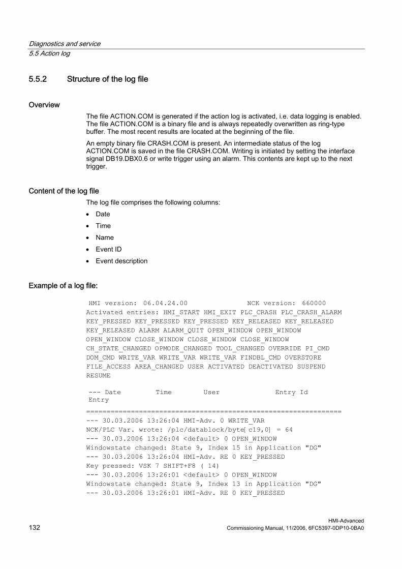
Diagnostics and service 5.5 Action log
HMI-Advanced 132 Commissioning Manual, 11/2006, 6FC5397-0DP10-0BA0
5.5.2 Structure of the log file
Overview The file ACTION.COM is generated if the action log is activated, i.e. data logging is enabled. The file ACTION.COM is a binary file and is always repeatedly overwritten as ring-type buffer. The most recent results are located at the beginning of the file. An empty binary file CRASH.COM is present. An intermediate status of the log ACTION.COM is saved in the file CRASH.COM. Writing is initiated by setting the interface signal DB19.DBX0.6 or write trigger using an alarm. This contents are kept up to the next trigger.
Content of the log file The log file comprises the following columns: • Date • Time • Name • Event ID • Event description
Example of a log file:
HMI version: 06.04.24.00 NCK version: 660000 Activated entries: HMI_START HMI_EXIT PLC_CRASH PLC_CRASH_ALARM KEY_PRESSED KEY_PRESSED KEY_PRESSED KEY_RELEASED KEY_RELEASED KEY_RELEASED ALARM ALARM_QUIT OPEN_WINDOW OPEN_WINDOW OPEN_WINDOW CLOSE_WINDOW CLOSE_WINDOW CLOSE_WINDOW CH_STATE_CHANGED OPMODE_CHANGED TOOL_CHANGED OVERRIDE PI_CMD DOM_CMD WRITE_VAR WRITE_VAR WRITE_VAR FINDBL_CMD OVERSTORE FILE_ACCESS AREA_CHANGED USER ACTIVATED DEACTIVATED SUSPEND RESUME
--- Date Time User Entry Id Entry =============================================================== --- 30.03.2006 13:26:04 HMI-Adv. 0 WRITE_VAR NCK/PLC Var. wrote: /plc/datablock/byte[c19,0] = 64 --- 30.03.2006 13:26:04 <default> 0 OPEN_WINDOW Windowstate changed: State 9, Index 15 in Application "DG" --- 30.03.2006 13:26:04 HMI-Adv. RE 0 KEY_PRESSED Key pressed: VSK 7 SHIFT+F8 ( 14) --- 30.03.2006 13:26:01 <default> 0 OPEN_WINDOW Windowstate changed: State 9, Index 13 in Application "DG" --- 30.03.2006 13:26:01 HMI-Adv. RE 0 KEY_PRESSED
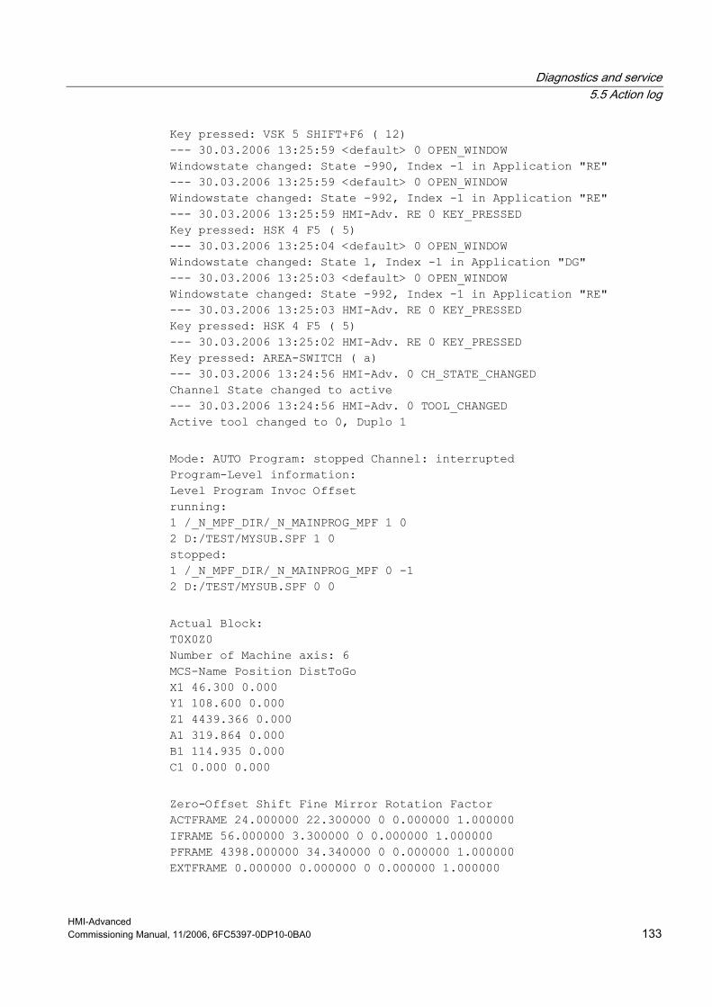
Diagnostics and service 5.5 Action log
HMI-Advanced Commissioning Manual, 11/2006, 6FC5397-0DP10-0BA0 133
Key pressed: VSK 5 SHIFT+F6 ( 12) --- 30.03.2006 13:25:59 <default> 0 OPEN_WINDOW Windowstate changed: State -990, Index -1 in Application "RE" --- 30.03.2006 13:25:59 <default> 0 OPEN_WINDOW Windowstate changed: State -992, Index -1 in Application "RE" --- 30.03.2006 13:25:59 HMI-Adv. RE 0 KEY_PRESSED Key pressed: HSK 4 F5 ( 5) --- 30.03.2006 13:25:04 <default> 0 OPEN_WINDOW Windowstate changed: State 1, Index -1 in Application "DG" --- 30.03.2006 13:25:03 <default> 0 OPEN_WINDOW Windowstate changed: State -992, Index -1 in Application "RE" --- 30.03.2006 13:25:03 HMI-Adv. RE 0 KEY_PRESSED Key pressed: HSK 4 F5 ( 5) --- 30.03.2006 13:25:02 HMI-Adv. RE 0 KEY_PRESSED Key pressed: AREA-SWITCH ( a) --- 30.03.2006 13:24:56 HMI-Adv. 0 CH_STATE_CHANGED Channel State changed to active --- 30.03.2006 13:24:56 HMI-Adv. 0 TOOL_CHANGED Active tool changed to 0, Duplo 1 Mode: AUTO Program: stopped Channel: interrupted Program-Level information: Level Program Invoc Offset running: 1 /_N_MPF_DIR/_N_MAINPROG_MPF 1 0 2 D:/TEST/MYSUB.SPF 1 0 stopped: 1 /_N_MPF_DIR/_N_MAINPROG_MPF 0 -1 2 D:/TEST/MYSUB.SPF 0 0 Actual Block: T0X0Z0 Number of Machine axis: 6 MCS-Name Position DistToGo X1 46.300 0.000 Y1 108.600 0.000 Z1 4439.366 0.000 A1 319.864 0.000 B1 114.935 0.000 C1 0.000 0.000 Zero-Offset Shift Fine Mirror Rotation Factor ACTFRAME 24.000000 22.300000 0 0.000000 1.000000 IFRAME 56.000000 3.300000 0 0.000000 1.000000 PFRAME 4398.000000 34.340000 0 0.000000 1.000000 EXTFRAME 0.000000 0.000000 0 0.000000 1.000000

Diagnostics and service 5.5 Action log
HMI-Advanced 134 Commissioning Manual, 11/2006, 6FC5397-0DP10-0BA0
TOTFRAME 0.000000 0.000000 0 0.000000 1.000000 ACTBFRAME 0.000000 0.000000 0 0.000000 1.000000 SETFRAME 12.000000 0.300000 0 0.000000 1.000000 EXTSFRAME 33.000000 2.300000 0 0.000000 1.000000 PARTFRAME 4354.000000 34.000000 0 0.000000 1.000000 TOOLFRAME 0.000000 0.000000 0 0.000000 1.000000 MEASFRAME 0.000000 0.000000 0 0.000000 1.000000 WPFRAME 0.000000 0.000000 0 0.000000 1.000000 Additional information on "State" and "Index" is provided in: References: HMI Programming Package, Part 1 Operator's Guide → "Sequence control"
5.5.3 Saving the log file
Requirements The actual log file is displayed in the operator area "Diagnostics" → "Service Displays" → "Action Log" on the screen (softkeys "MMCWIN file" and "Crash Log").
Log file after initiating the trigger The file CRASH.COM is generated in the following cases: • If the interface signal DB19.DBX0.6 "Save action log" changes from 0 to 1. • If the alarm entered in field "Write trigger via alarms" occurs. The PLC must set and reset the bit at the user interface (same as, e.g. key lock, screensaver control, etc.). HMI-Advanced evaluates the rising edge of the signal (i.e. a transition from 0 to 1) and creates the log file when the signal arrives. HMI-Advanced only read-accesses the data, i.e. the user must reset the signal in the PLC program. If the bit is already set when the HMI starts up, HMI-Advanced does not respond to the value of the bit (until it is reset and set again).
Saving logs To read out the log files, proceed as follows: 1. In order to save the log files, select "Save log".
The following files can be saved: – ACTION.COM (binary file) – ACTION.LOG – CRASH.COM (binary file) – CRASH.LOG
2. The logs are saved under ..\Diagnosis\Log files. Select e.g. "Services" → "Data Out" → "Disk", in order to read-out the log file.
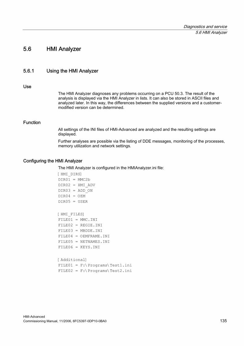
Diagnostics and service 5.6 HMI Analyzer
HMI-Advanced Commissioning Manual, 11/2006, 6FC5397-0DP10-0BA0 135
5.6 HMI Analyzer
5.6.1 Using the HMI Analyzer
Use The HMI Analyzer diagnoses any problems occurring on a PCU 50.3. The result of the analysis is displayed via the HMI Analyzer in lists. It can also be stored in ASCII files and analyzed later. In this way, the differences between the supplied versions and a customer-modified version can be determined.
Function All settings of the INI files of HMI-Advanced are analyzed and the resulting settings are displayed. Further analyses are possible via the listing of DDE messages, monitoring of the processes, memory utilization and network settings.
Configuring the HMI Analyzer The HMI Analyzer is configured in the HMIAnalyzer.ini file: [HMI_DIRS] DIR01 = MMC2b DIR02 = HMI_ADV DIR03 = ADD_ON DIR04 = OEM DIR05 = USER [HMI_FILES] FILE01 = MMC.INI FILE02 = REGIE.INI FILE03 = MBDDE.INI FILE04 = OEMFRAME.INI FILE05 = NETNAMES.INI FILE06 = KEYS.INI [Additional] FILE01 = F:\Programs\Test1.ini FILE02 = F:\Programs\Test2.ini

Diagnostics and service 5.6 HMI Analyzer
HMI-Advanced 136 Commissioning Manual, 11/2006, 6FC5397-0DP10-0BA0
Section [HMI_DIRS] All the directories that are to be used for analyzing the INI files are entered here. Section [HMI_FILES] All the INI files that are to be used for analysis are entered here. At the same time, the files in the directories that are entered under HMI_DIRS are searched and analyzed. Section [Additional] Additional INI files that are not subject to the INI concept of HMI-Advanced, i.e. INI files from add-on applications, can be entered here. The complete path is needed for the entries. Only the file of this path is analyzed.
5.6.2 Using the HMI Analyzer
Overview When the HMI Analyzer is started, the settings in the initialization file HMIAnalyzer.ini are analyzed. The point selected in the tree to the left is analyzed. The result of the analysis is displayed as a list on the right side. The result of the analysis can be saved as a "profile". All of the items marked in the tree are saved (toggle key or double-click on the respective box).
Figure 5-9 Example of .ini files
Saving the current data (profile) The profile of the currently selected items can be saved via the menu item "File" → "Save Profile". The menu item is only active if items for saving in the profile are marked in the tree. When saving, a sub-directory is created in the directory in which the HMI Analyzer is located. The name of the directory is composed of the date and time at the time the data was saved.

Diagnostics and service 5.6 HMI Analyzer
HMI-Advanced Commissioning Manual, 11/2006, 6FC5397-0DP10-0BA0 137
Example: "20060122_083755" for saving on January 22, 2006 at 08:37:55. All of the INI files marked at this time in this directory are saved as profiles. For the INI files saved as profiles are the "resultant" INI files. In this way, the profile shows the current valid configuration. The result files can be considered individually in an external ASCII editor.
Deleting the current data (profile) Individual profiles can be deleted from the hard disk via the menu item "File" → "Delete Profile".
Comparison of two saved profiles By selecting the menu item "File" → "Compare" in the main window, two saved profiles (configurations) can be compared to each other. All previously saved profiles are listed in the "Available Profiles" list. The profile selected in the list is selected for comparison using the the key "Add à" and moved to the "Compared Profiles" list. The first selected profile is considered as the original, the second selected profile is considered the modified profile. A profile can be moved back into the list using the "ß Remove" button. The sequence in the list can be changed via arrow right. The "Compare" button can be used as soon as two profiles in the "Compared Profiles" list are selected for comparison. After the comparison is done, the result is displayed in the main window of the application and the selection window is closed.
Figure 5-10 Comparing profiles
The result of the comparison can be seen in the main window of the application. The result of the comparison can also be saved in an ASCII file via the menu items "File" → "Save Comparison". A saved comparison result can be displayed again by the HMI Analyzer via the menu items "File" → "View Comparison".

Diagnostics and service 5.6 HMI Analyzer
HMI-Advanced 138 Commissioning Manual, 11/2006, 6FC5397-0DP10-0BA0
5.6.3 Analyzing INI Files
System → Files All entries of the analyzed INI files are displayed here.
HMI Display of the corresponding INI entries from files that are subject to the
INI concept of HMI-Advanced. The directory from which the entry comes is also displayed ("Source" column). For this, all the directories that are entered under HMI_DIRS in HMIAnalyzer.ini are scanned.
Additional files Display of the addition INI files that are not subject to the INI concept, i.e. these INI files are only searched for in the specified path.
System → Hardware Resources
Hardware Under hardware, parts of the existing hardware are listed, e.g. information on the processor and information on the individual hard disk partitions and drives.
Memory More precise information on the existing and available memory is displayed here in KB:
Used Memory: Percent of allocated memory Physical Memory, total: Total size of the RAM Physical Memory, available: Free, available RAM memory Page File, total : Total memory of the swap file Page File, available: Free, available memory of the swap file Virtual Memory, total: Total size of the virtual memory Virtual Memory, available: Free, available virtual memory
System → Software Environment
Running Tasks The memory usage and the running of all active processes are displayed here.
The following columns are displayed:
Name Name of the process Running "X" process is running
'-' process was ended ProcessID Process ID WorkingSetSize Current memory usage in kB DiffWorkingSetSize Modification of the memory since the start of the HMI
Analyzer or since the last reset PagePoolUsage Swap memory in KB
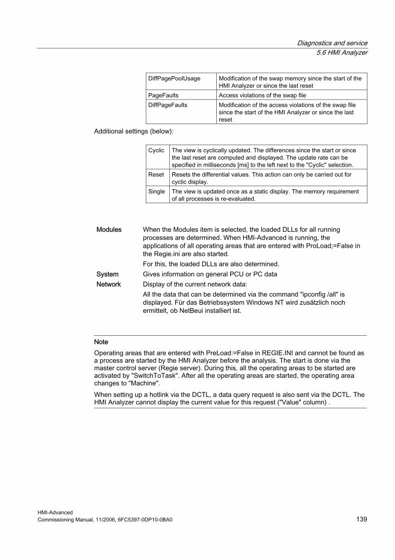
Diagnostics and service 5.6 HMI Analyzer
HMI-Advanced Commissioning Manual, 11/2006, 6FC5397-0DP10-0BA0 139
DiffPagePoolUsage Modification of the swap memory since the start of the HMI Analyzer or since the last reset
PageFaults Access violations of the swap file DiffPageFaults Modification of the access violations of the swap file
since the start of the HMI Analyzer or since the last reset
Additional settings (below):
Cyclic The view is cyclically updated. The differences since the start or since the last reset are computed and displayed. The update rate can be specified in milliseconds [ms] to the left next to the "Cyclic" selection.
Reset Resets the differential values. This action can only be carried out for cyclic display.
Single The view is updated once as a static display. The memory requirement of all processes is re-evaluated.
Modules When the Modules item is selected, the loaded DLLs for all running processes are determined. When HMI-Advanced is running, the applications of all operating areas that are entered with ProLoad;=False in the Regie.ini are also started. For this, the loaded DLLs are also determined.
System Gives information on general PCU or PC data Network Display of the current network data:
All the data that can be determined via the command "ipconfig /all" is displayed. Für das Betriebssystem Windows NT wird zusätzlich noch ermittelt, ob NetBeui installiert ist.
Note Operating areas that are entered with PreLoad:=False in REGIE.INI and cannot be found as a process are started by the HMI Analyzer before the analysis. The start is done via the master control server (Regie server). During this, all the operating areas to be started are activated by "SwitchToTask". After all the operating areas are started, the operating area changes to "Machine". When setting up a hotlink via the DCTL, a data query request is also sent via the DCTL. The HMI Analyzer cannot display the current value for this request ("Value" column) .

Diagnostics and service 5.6 HMI Analyzer
HMI-Advanced 140 Commissioning Manual, 11/2006, 6FC5397-0DP10-0BA0
5.6.4 Application Examples
(1) OEM application that is linked-in does not start Problem: An OEM application was linked into HMI-Advanced, but it does not start after actuating the corresponding softkey or it starts another application.
Possible cause: Due to the hierarchical execution of the HMI directory, the entry made in the Regie.ini file was overwritten by an entry in another regie.ini file with a higher priority and is therefore not in effect. For example, an entry was made in the OEM directory: [TaskConfiguration] Task6 = name := TestApp, Timeout := 10000, PreLoad := True This is then overwritten in the user directory: [TaskConfiguration] Task6 = <empty>
Figure 5-11 Checking the start of the OEM application
HMI Analyzer: Under Files → HMI, the regie.ini is selected. The resulting regie.ini file from all the HMI directories is now displayed (mmc2, hmi_adv, add_on, oem, user). Now it becomes clear whether the entry that was made is also truly active or was overwritten by another entry. In addition, it is possible to recognize which HMI directory the entry comes from.

Diagnostics and service 5.6 HMI Analyzer
HMI-Advanced Commissioning Manual, 11/2006, 6FC5397-0DP10-0BA0 141
(2) No connection to the NCU/PLC Problem: In spite of adaptation to the NCU/PLC address in the mmc.ini file, no connection to the NCU/PLC can be established.
Possible cause: Due to the hierarchical execution of the HMI directory, the entry made in the mmc.ini file was overwritten by an entry with a higher priority and is therefore not in effect. For example, an entry was made in the OEM directory: [NCU840D] ADDRESS0=5,NAME=/NC,SAP=d ADDRESS1=6,NAME=/PLC,SAP=1 This is then overwritten in the user directory: [NCU840D] ADDRESS0=14,NAME=/NC,SAP=d ADDRESS1=14,NAME=/PLC,MAX_BUB_CYCLICS=0
Figure 5-12 Checking the connection to the control
HMI Analyzer: Under Files → HMI, the mmc.ini is selected. The resulting mmc.ini file from all the HMI directories is now displayed (mmc2, hmi_adv, add_on, oem, user). Now it becomes clear whether the entry that was made is also truly active or was overwritten by another entry. In addition, it is possible to recognize which HMI directory the entry comes from.

Diagnostics and service 5.6 HMI Analyzer
HMI-Advanced 142 Commissioning Manual, 11/2006, 6FC5397-0DP10-0BA0
(3) Blocking, very slow system Problem: The system is very slow and blocks the area switcher completely in some aspects. After a certain period of time, all the operating actions are suddenly processed sequentially.
Possible causes: The area application that is newly selected by the area switcher sets up hotlinks when loading. When loading a form with DCTL, the message DDEInitialize is sent to the main window of all processes. If a main window is very slow to answer or does not answer this notification, then this can be the cause of the slow or blocked area switcher. Rule: "Top-level" windows must not be allowed to block the system for a long period of time. DDE Clients may not use the DDEML. They must use the DCTL.
HMI Analyzer: Select the DDE/Ping Windows item. Now you can check whether all windows answer the DDE broadcasts while the cyclic operation is being started. The "Answer Time" should be set to 100 ms and the cycle time of the query "Cyclic Time" to 1000 ms. The checkmark for Append should be set and the checkmark for ShowAll should be removed. The applications that appear in the list have not answered within the answer time. The displayed applications can be the reason for the slow, blocking system.
Note Clients that establish DDE connections during operation are particularly affected. Clients that still use the DDEML should change to DCTL or limit the establishing of connections to the application start. The problem is only solved after the 32 Bit DCTL. VB4.0 programs must be ported accordingly. For systems without much memory, the problem occurs more often. All of the processes exported to the hard disk must be loaded into the main memory (e.g. DDE initialize) and executed. This is very time-sensitive. Examples for time-critical applications are database accesses, complex computation programs, etc. Background processes, in particular, must be programmed in such a way that the applications that are running in the foreground are not blocked.
Diagnostics and service 5.6 HMI Analyzer
HMI-Advanced Commissioning Manual, 11/2006, 6FC5397-0DP10-0BA0 143
(4) Slow communication times Problem: If too many hotlinks are set up, the communication times are significantly slowed down.
Possible causes: Depending on the load on the PLC, the number of hotlinks that are causing problems differs. Hotlinks represent a basic load for the control and as few as possible should be used.
HMI Analyzer: The HMI Analyzer must be started prior to starting HMI-Advanced. This can be done in service mode. After HMI-Advanced has been booted, the HMI Analyzer displays the actually existing hotlinks under DDE → Message. Using the "Only Active Hotlinks" option, all active hotlinks can now be displayed. A check must now be made as to which data accesses will not need to be implemented as hotlinks but can also be implemented as a request. By doing this, the basic load on the control can be reduced. Using the filter request, poke or execute, you can check whether these DDE functions are burdening the system. Cyclic requests with short cycle times burden the system. The cycle time can be determined from the "Time" column. This column displays the time that has elapsed since the start of windows in milliseconds.
Note OPC DataAccess programmer When programming an OPC Client Application, the variables to be read are automatically set up as a hotlink if a variable of the respective group is defined as a hotlink. In addition, PLC variables for SINUMERIK OPC Server are automatically (Flag IsActive=True) set up as a hotlink.

Diagnostics and service 5.6 HMI Analyzer
HMI-Advanced 144 Commissioning Manual, 11/2006, 6FC5397-0DP10-0BA0

HMI-Advanced Commissioning Manual, 11/2006, 6FC5397-0DP10-0BA0 145
List of the INI Files APlease observe:
This chapter provides an alphabetical listing of all INI files indicating the sections that can be changed by the machine manufacturer or end user. All other sections must not be changed!
See also ACTLOG.INI (Page 146) AEDITOR.INI (Page 147) DINO.INI (Page 148) DG.INI (Page 149) DGOVW.INI (Page 150) DH.INI (Page 151) DPDH.INI (Page 151) DPSIM.INI (Page 151) HEADER.INI (Page 152) HMIDESK.INI (Page 156) IB.INI (Page 157) IF.INI (Page 158) KEYS.INI (Page 159) LOGDRIVE.INI (Page 159) MACHINE.INI (Page 162) MBDDE.INI (Page 165) MMC.INI (Page 169) NETNAMES.INI (Page 174) OEMFRAME.INI (Page 177) PARAM.INI (Page 177) PARAMTM.INI (Page 178) REGIE.INI (Page 178) SEDITOR.INI (Page 180) SIMTOGEO.INI (Page 187) TASKCONF.INI (Page 189)

List of the INI Files A.1 ACTLOG.INI
HMI-Advanced 146 Commissioning Manual, 11/2006, 6FC5397-0DP10-0BA0
A.1 ACTLOG.INI
Overview The settings from the screen "Action log settings" are combined and from this a configuration file ACTLOG.INI generated.
Note We recommended that the action log is configured using the setting dialog boxes and not using this file.
Setting the spindle number When logging the program status, as standard, the spindle speeds of the first spindle are recorded. Other spindles can also be set in the ACTLOG-INI. The entry IpoSpindleNum=Spindel Index must be changed to to the required Spindelindex in the section [ActionLogSettings]: [ActionLogSettings] ActionLogPath=E:\AC_LOG\crash.com ActionLogSize=5000000 ActionLogBufSize=65536 AlarmLogPath=E:\AC_LOG\crash.com AlarmLogSize=5000000 AlarmLogBufSize=4096 CrashLogPath=E:\AC_LOG\crash.com CrashLogSize=5000000 DomainBufSize=20 PLCAlarms=3000 TripIds=0FFF380000000000000000000000000000000000000001F000000000000 WriteInterval=-1 IpoTrace=1 IpoChannelNum=1 IpoSpindleNum=3
List of the INI Files A.2 AEDITOR .INI
HMI-Advanced Commissioning Manual, 11/2006, 6FC5397-0DP10-0BA0 147
A.2 AEDITOR.INI
Overview Information about the ASCII editor can be found in the AEDITOR.INI file. The data regarding the size of the files that can be edited is in the section [MEMORY]. [MEMORY] MemFactor=f ; f stands for 8 MB units. Permissible values are 1<=f<=31 ; corresponding to 8 MB to 248 MB Editor access authorizations are influenced in the Section [ACCESSLEVEL]: [ACCESSLEVEL] GlobalReplace=6 SettingHiddenCheck=7 Enable_Simulation = 7 ; in the Editor, the Simulation softkey can be hidden. [MMC_Wizard] AEDITOR=AEDITOR.COM [MEMORY] ; default factor for maximum size of file ; valid values are: from 1 to 31 ; factor x (1<=x<=31) means: you can edit a file up to a ; maximum size of x * 8 MB ; for example: factor 1 = maximum size of 8 MB, 31 = 248 MB ; attention: a greater factor needs more RAM ; the application can override this default factor MemFactor=2 ; default factor for maximum size of buffer file for editing NC domains ; see explanation for MemFactor above ; the factor should be great enough for the whole NCU-memory ; the application cannot override this default factor MemNCFactor=2 ; Number of steps (input lines!), that the ASCII editor ; can reset (Undo)/restore (Redo). ; Default=0: No Undo/Redo steps can be activated ; > 0 max. 32767 only applies if the setting for UndoHandling does not equal 2. NrOfUndoSteps=10 ; Mode for Undo/Redo handling (synchronization with application): ; UndoHandling=0 Automatic: Application responds immediately to
List of the INI Files A.3 DINO.INI
HMI-Advanced 148 Commissioning Manual, 11/2006, 6FC5397-0DP10-0BA0
Ctrl+Z, CTRL+Y, Default ; UndoHandling=1 active application is informed that Ctrl+Z, CTRL+Y has come, application-specific response ; UndoHandling=2 no Undo/Redo functionality UndoHandling=0 ; Also applies to NC files ; EnableUndoOnNc=1 NC file is also processed with Undo/Redo With this mode it takes longer to prepare the NC file for processing in the HMI. ; EnableUndoOnNc=0 NC file is not processed with Undo/Redo�; (Default) EnableUndoOnNc=0 [STEPS] ; maximum number of blocks to search for a step, 0 == no limit MaxNrOfBlocks=1500 [ACCESSLEVEL] GlobalReplace=6 SettingHiddenCheck=7 Enable_Simulation=7 ; Protection level for softkey Simulation in Editor
A.3 DINO.INI
Overview The access authorizations for series commissioning are assigned in the file DINO-INI and additional settings are defined for the archive. [ACCESSLEVEL] USER=3 ; read authorization for series commissioning ; customer password (standard) PROGRAMMER=4 ; setup authorization for series commissioning ; corresponds to key-operated switch 3 (standard) [Function] ; 0: ISO-formatted paper tape is not supported ; 1: ISO-formatted paper tape is supported IsoActive=0 ; 1: ask before overwriting CFG_RESET.INI, 0: don't ask Ask_for_CFG_RESET.INI=0 ; Directory to store ISO-formatted programs from ; ISO paper tape archive ; Not changeable by user interface (supported if IsoActive=1) ISO-Path=/_N_WKS_DIR/_N_SHOPMILL_WPD

List of the INI Files A.4 DG.INI
HMI-Advanced Commissioning Manual, 11/2006, 6FC5397-0DP10-0BA0 149
; writing ISO paper tape archive: ; 1: accept ISO programs only in ISO Path, ; 0: accept in all directories ; Not changeable by user interface (supported if IsoActive=1) AcceptOnlyISO-Path=1 ; 1: first unpack and then delete ZIP-files while reading ; a commissioning archive, ; 0: don't unpack, but store ZIP files in database ; not changeable by user interface UnPack=1 ; time to wait after a PLC memory reset in seconds Wait for PLC=20 ; reading internal pc-formatted archive that is not a setup archive: ; 0: destination of the unpacked files is determined through perhaps ; existing files with same name, if no such file exists destination ; is MMC ; else: destination is determined from the file header, ; i.e. from the location where the file was read from TakeDestinationFromHeader=0
A.4 DG.INI
Overview In the operator area "Diagnostics", the access to individual softkeys can be individually set by entering the protection level. Enter the required protection level in the DG.INI file under [ACCESSLEVEL]:
[ACCESSLEVEL] ALARMS=7 ; Alarms SERVICE=7 ; Service displays COMMUNIC-LOG=3 ; Communications log PLC=3 ; PLC status PLC-CHANGE=2 ; PLC status: SK "Change Value" (change)
; SK "Reset Value" (undo the change) ; SK "Commit Value" (accept the change) ; interlocked using the manufacturer's password
REMOTE-DIAGNOSIS=4 ; Remote diagnostics FILE=7 ; File functions RUN-LOG=7 ; Softkey "Action log" interlocked using the
user password

List of the INI Files A.5 DGOVW.INI
HMI-Advanced 150 Commissioning Manual, 11/2006, 6FC5397-0DP10-0BA0
A.5 DGOVW.INI
Overview This file is used for configuring additional user-specific signals in Diagnostics → Service Displays, "Service Overview" screen. Configured signals are added below the standard signals in this screen and can be viewed there (scrolling may be required). The file must be created explicitly in the directory mmc2 or addon, oem, user. [GLOBAL] ; Number of additional signals NrOfSignals= ; Bitmaps with customized icons to be displayed [BMP] 100="<Bitmapname>" 101="..." . . ; One section per signal [SIG1] text= Item= expr= . . [SIG2] . . [SIG<n>] . .
DGOVWTXT_xx.INI The value “xx” in the file name contains the language abbreviation. The file contains the language-specific texts for user-specific signals in the service overview. The file must be created explicitly in the mmc2 or user, addon, oem or …\language directory. [TEXT] ; $T<Nr> = "Language-specific text" ; <Nr> stands for values from 1000 to 32767, values below 1000 are reserved. ; Example: $T1001="Signal s"

List of the INI Files A.6 DH.INI
HMI-Advanced Commissioning Manual, 11/2006, 6FC5397-0DP10-0BA0 151
For details on configuring and for an example, refer to:
See also Supplementing service displays on a user-specific basis (Page 36)
A.6 DH.INI
Overview The access authorizations for directories of the data management are defined in the file DH.INI. [ACCESSMASKS] \wks.dir\*.wpd\*.mpf = 75775 \mpf.dir\*.mpf = 75775 \cus.dir\*.spf = 33773
A.7 DPDH.INI
Overview Access authorizations for processing/editing workpiece programs are configured in the file DPDH.INI. [ACCESSLEVEL] PROGRAMMER=4 OPERATOR=5 ENABLE_DIALPROG=0 SetStandardWpSave=2 ENABLE_SIMULATION=7
A.8 DPSIM.INI
Overview The run environment for the simulation is set in the file DPSIM.INI. [ACCESSLEVEL] ;minimum level for changing setup standard: SETUP=1 USER=3 OPERATOR=5

List of the INI Files A.9 HEADER.INI
HMI-Advanced 152 Commissioning Manual, 11/2006, 6FC5397-0DP10-0BA0
[MAIN] ;<>0: simulate program external modal (see also ; EXTERN_SIZE,EXTERN_CHECK) EXTERN_MODAL=0 ; simulate program external modal, if program ; size >= EXTERN_SIZE ; only if EXTERN_MODEL<>0 EXTERN_SIZE=150000 ; only if EXTERN_MODEL<>0 EXTERN_CHECK=1 ; <>0: reset tool data, if new workpiece is selected ; =0: use current tool data, if new workpiece is selected SIM_LOAD_TOOLS=1 [PRELOAD] ;=1: TO_INI.INI and TO_ADDON.INI are preloaded by DPNCSIM.EXE ;=0: TO_INI.INI and TO_ADDON.INI are loaded by simulation TOOLS=0 ;= 1: all cycles are preloaded by DPNCSIM.EXE ; if section MAIN, entry CYCLE is set, additionally all cycles from shadow directory are preloaded by DPNCSIM.EXE ;= 0: cycles are loaded by simulation, if cycle is called CYCLES=1 ;=2: load for simulation to \CUS.DIR, \CMA.DIR or \CST.DIR (default) ; load only cycles from NCK ; only evaluated if [MAIN]CYCLE is set and [PRELOAD]CYCLES=1 ;=0: load all cycle (from NCK and MMC) for simulation to ; \CUS.DIR, \CMA.DIR or \CST.DIR ; only evaluated if [MAIN]CYCLE is set and [PRELOAD]CYCLES=1 ;=1: use the cycle interface under \DP.DIR\SIM.DIR CYCLEINTERFACE=2
A.9 HEADER.INI
Overview User-specific icons and texts are configured in the HEADER.INI file that are output in the global cross-channel status display (header). [CondStopIcons] DefaultIcon=CondWait.bmp ;0 = No wait state
1=CondStop.bmp ;No NC ready 2=CondStop.bmp ;No ModeGroup ready 3=CondStop.bmp ;EMERGENCY STOP active

List of the INI Files A.9 HEADER.INI
HMI-Advanced Commissioning Manual, 11/2006, 6FC5397-0DP10-0BA0 153
4=CondStop.bmp ;Alarm active with stop 5=CondStop.bmp ;M0 / M1 active 6=CondStop.bmp ;Block ended in single block mode 7=CondStop.bmp ;NC Stop active 8=CondStop.bmp ;Read-in enable missing 9=CondStop.bmp ;Feed enable missing 10=CondWait.bmp ;Dwell time active 11=CondWait.bmp ;Aux. function acknowledgment missing 12=CondStop.bmp ;Axis enable missing 13=CondWait.bmp ;Exact stop not reached 14=CondWait.bmp ;Waiting for positioning axis 15=CondWait.bmp ;Waiting for spindle 16=CondWait.bmp ;Waiting for other channel 17=CondStop.bmp ;Waiting for feed override 18=CondStop.bmp ;Error in NC block 19=CondStop.bmp ;Waiting for external NC blocks 20=CondWait.bmp ;Waiting for synchronous action 21=CondWait.bmp ;Block search active 22=CondStop.bmp ;No spindle enable 23=CondStop.bmp ;Axis feed override 0 24=CondWait.bmp ;Waiting for tool change acknowledgment 25=CondWait.bmp ;Gear stage change 26=CondWait.bmp ;Waiting for position control 27=CondWait.bmp ;Waiting for thread cut 28=CondWait.bmp ;Reserved 29=CondWait.bmp ;Waiting for punching 30=CondWait.bmp ;Waiting for safe operation 31=CondWait.bmp ;No channel ready 32=CondStop.bmp ;Oscillation active 33=CondWait.bmp ;Axis replacement active (block change
inhibited because axis replacement in progress)
34=CondWait.bmp ;Axis container rotation 35=CondWait.bmp ;AXCT: Following axis active 36=CondWait.bmp ;AXCT: Leading axis active 37=CondWait.bmp ;AXCT: Follow up mode active 38=CondWait.bmp ;AXCT: Internal status change 39=CondWait.bmp ;AXCT: Axis/spindle inhibit 40=CondWait.bmp ;AXCT: Corr. motion active
;Axis container replacement: Superimposed motion
41=CondWait.bmp ;AXCT: Axis replacement active 42=CondWait.bmp ;AXCT axis interpolator active

List of the INI Files A.9 HEADER.INI
HMI-Advanced 154 Commissioning Manual, 11/2006, 6FC5397-0DP10-0BA0
43=CondWait.bmp ;Waiting for compile cycle 44=CondWait.bmp ;Access to system variable 45=CondStop.bmp ;Search target found (;block search has found
search target and the NCK has stopped)
46=CondWait.bmp ;Rapid return initiated 47=CondWait.bmp ;AXCT: Waiting for spindle stop
;Axis container exchange
48=CondWait.bmp ;Machine data alignment (;New-Config) 49=CondWait.bmp ;Axis exchange: Axis in coupling 50=CondWait.bmp ;Axis exchange: Liftfast active 51=CondWait.bmp ;Axis exchange: New-Config active 52=CondWait.bmp ;Axis exchange: AXCTSW active 53=CondWait.bmp ;Axis exchange: Waitp active 54=CondWait.bmp ;Axis in another channel 55=CondWait.bmp ;Axis exchange: Axis PLC axis 56=CondWait.bmp ;Axis exchange: Axis oscillating axis 57=CondWait.bmp ;Axis exchange: Axis jog axis 58=CondWait.bmp ;Axis exchange: Command axis 59=CondWait.bmp ;Axis exchange: Axis OEM axis 60=CondWait.bmp ;Coupled following axis 61=CondWait.bmp ;Coupled-motion following axis 62=CondWait.bmp ;Coupled slave axis 63=CondWait.bmp ;Hold at cycle end M0 64=CondWait.bmp ;Hold at cycle end M1 65=CondWait.bmp ;Wait: Axis is at endstop 66=CondWait.bmp ;"Master-Slave changeover active" 67=CondWait.bmp ;"Axis exchange: Axis single axis" 68=CondWait.bmp 69=CondWait.bmp ;"Synchronism: Synchronous spindle" 70=CondWait.bmp ;"Switch-off position synch. spindle" 71=CondWait.bmp ;"Wait for enable of the transformer axis" 72=CondWait.bmp 73=CondWait.bmp
[Pos1] ChanStatFeedStopSpindleStop = 1 ;channel status, channel 1 is displayed, superimposed Spindles=1,2 ;from feed inhibit channel 1 and spindle inhibit ;for spindles 1 and 2 [Pos3] SpindStat=1 ;spindle status of spindle 1
List of the INI Files A.9 HEADER.INI
HMI-Advanced Commissioning Manual, 11/2006, 6FC5397-0DP10-0BA0 155
;ChanStatFeedStop = 3 ;channel status, channel 3 is displayed, superimposed ;from feed inhibit, channel 3 [Pos5] ChanStat = 2 ;channel status, channel 2 is displayed ;SpindStat= 3 ;spindle status, spindle 3 is displayed [Pos9] ChanStatFeedStopSpindleStop = 1 ;channel status, channel 1 is displayed, superimposed Spindles=1 ;from feed inhibit channel 1 and spindle inhibit ;of Spindle 1 [Pos11] ChanStatFeedStop = 2 ;channel status, channel 2 is displayed, superimposed ;from feed inhibit, channel 2 [Pos13] SpindStat=2 ;spindle status of spindle 2 [Pos15] ChanStatFeedStopSpindleStop = 1 ;channel status, channel 1 is displayed, superimposed Spindles=1 ;from feed inhibit channel 1 and spindle inhibit ;of Spindle 1 [UserIcons] ;UI_0 = <name.bmp> , <Position> ;name of the icon, position ... ;UI_31 = <name.bmp> , <Position> ;name of the icon, position ;USER_ICON_BASE = DBxx.DBByy ; number of the data block with the ; double word for user icon ; yy start byte of the double word [UserTextInfo] ;USER_TEXT_BASE = DBxx.DBByy ; xx data block with interface for ; user messages in the header ; yy start byte for interface ; TextLength=33 ; activate text limiting, if ; user texts are used. [OemIcons] ;Oem_ICON_BASE=DBxx.DBByy ;OI_0= = <name.bmp> , <Position> ;name of the icon, position

List of the INI Files A.10 HMIDESK.INI
HMI-Advanced 156 Commissioning Manual, 11/2006, 6FC5397-0DP10-0BA0
... ;OI_31 = <name.bmp> , <Position> ;name of the icon, position [OEMTextInfo] ;OEM_NUMBER_TEXTFIELD=3 ;There are a max. of 3 text fields per line, i.e. ;a total of 6 text fields in two lines are possible. ;The output length is limited to max. 38 characters ;per line. ;OEM_TEXT_BASE=DBxx.DBByy
A.10 HMIDESK.INI
Overview Settings are only necessary in this file if HMI-Advanced is installed on a programming device or standard PC. [Global] ;Global configuration data ;definition of the desktop (minimum 2, maximum 4) NumberOfDesktops = 2 ;Control mode for using the mouse: Task bar ControlMode = Icon KeyboardControl = False [Desktop1] [Desktop2] ;Active desktop with task bar Explorer = True ; ;Automatic start of an application after creating the desktop ; Start Regie StartupApplication = "rngkrnl.exe" ; ;Desktop with customized color scheme SetHMIColors = True ; ;Definition of start time CreateDesktop = Immediately ; ;Keep user interface in foreground in window mode WindowOnTop = False [Desktop3] [Desktop4].

List of the INI Files A.11 IB.INI
HMI-Advanced Commissioning Manual, 11/2006, 6FC5397-0DP10-0BA0 157
A.11 IB.INI
Overview Softkey access in the "Start-up" operating area can be set individually by entering the protection level. Enter the required protection level in section [ACCESSLEVEL]. The operator languages are defined in Section [LANGUAGE]. [ACCESSLEVEL] RESET =2 ;NCK reset NCK reset CHG_SCL_SYS=5 ;change scaling system, system of dimensions, inch/metric MASCHDAT =4 ;Machine data DRIVE_CFG=2 ;Drive configuration BOOTFILE=2 ;Boot file MOT_CTRL=2 ;Motor/Valve selection VIEW=2 ;User views + Display options NC_ADDR=2 ;NCK address SETUP_SWITCH=2;commissioning switch PLC_STATE=3 ;plc state PLC_DATE=3 ;plc date PLC-CHANGE=2 ;PLC status : ;Sk Change Value (change) ;Sk Reset Value (undo change) ;Sk Commit Value (accept change) Interlocked by manufacturer DRIVE_SERVO=2 ;Drives/Servo SET_COL=3 ;colors SYST_SETTINGS=4 ;system settings SET_LANG=2 ;Language SET_BTSS=2 ;Operator panel OPTION=2 ;Options EDIT=1 ;Editor DOS=1 ;DOS shell TOOL_MNG=3 tool management FILE=7 ;File functions PASSWD=3 ;Set/Delete password Change and delete password CHG_PASSWD=7 ;SK "password ..." CHANGE_LANG=7 ;change language [LANGUAGE] ;Softkey select language instead of softkey change language in the main ;menu of area setup. ;False: Softkey change language to toggle between the foreground ; and background language.
List of the INI Files A.12 IF.INI
HMI-Advanced 158 Commissioning Manual, 11/2006, 6FC5397-0DP10-0BA0
;True: Softkey select language instead of softkey change language ; to select one of the installed languages. To use this add the ; following values to the entries of the LANGUAGE section in the ; mmc.ini: ;LanguageList= ... , GR ;FontList= ... , Europe ;FontListKO= ... , Europe2 ;LBList= ... , German SkSelectLngInsteadSkChangeLng=False
Note In the [HELP_EXTENSION] section, the HelpFileExtension parameter must be set to 0 (WinHelp) if you want old, OEM-specific help files with the extension *.hlp to be displayed.
A.12 IF.INI
Overview Functions to parameterize the help function and to output language-specific texts are available in the file IF.INI: [TECHNOLOGY] ; "m" = milling ; "t" = turning ; "g" = grinding ; "s" = nibbling ; "p" = punching ; "a" = display all technologies ; Notation in the section e.g.: Technology=m [TEXTFILES] ; Siemens = Dh\Cst.dir\Ifs_gr.com ; SiemensI= Dh\Cst.dir\IfIT_gr.com turning ISO or ; SiemensI= Dh\Cst.dir\IfIM_gr.com milling ISO ; machinery construction OEM = Dh\Cst.dir\IfM_gr.com ; machinery construction OEM = Dh\Cst.dir\IfI_gr.com ; end user = Dh\Cst.dir\USER_gr.com ; Notation in the section e.g.: Siemens=Cst.dir\ifs_gr.com SiemensI=Cst.dir\ifit_gr.com Manufacturer= … End user=

List of the INI Files A.13 KEYS.INI
HMI-Advanced Commissioning Manual, 11/2006, 6FC5397-0DP10-0BA0 159
[CONTEXT] ; = 0 context sensitivity not active ; = 1 context sensitivity active ; Notation in the section e.g.: Extended_Sensivity=1 [TEXTSEARCH] ; = 1 text search only for instruction texts ; = 2 text search only for descriptive texts ; = 3 text search for instruction and descriptive texts ; Notation in the section e.g.: Search type=3
A.13 KEYS.INI
Overview Entries in this file allow the use of hardkeys of the operator panel front OP 010 and OP 010C or SINUMERIK keyboards with hotkey block and PLC softkeys. Reference: Commissioning Manual "Supplementing the operator interface", Chapter "Configuring OP hotkeys and PLC keys".
A.14 LOGDRIVE.INI
Overview In the file LOGDRIVE.INI, logical drives are linked-in and the associated access authorizations assigned. [PCU] ; device name of PCU for USB local UsbFront=G: ; device name of PCU UsbX203=H: UsbX204=I: ; - <SEARCH PATH> : USER, OEM, ADD_ON, HMI_ADV, MMC2 ; - it can be set up to 8 net devices or usb devices ; - for each device access rights can set for the applications program, machine or services ; missing access rights are set to 7 (no limit) by default ; - all entries for net device are ignored if the software option (Network drive management) is not set ; - all usb devices are ignored, if no tcu configuration exist. ACTTCU:\\FRONT always can be set ; all files LOGDRIVE.INI of the <SEARCH PATH> are read and the
List of the INI Files A.14 LOGDRIVE.INI
HMI-Advanced 160 Commissioning Manual, 11/2006, 6FC5397-0DP10-0BA0
contents is merged ; display machine data are append after the last entry of LOGDRIVE.INI, ; but the maximum is limited to 8 net devices at all ; $MM_CMM_DIRECTORY_SOFTKEY_PATH1 (MD 9676) to $MM_CMM_DIRECTORY_SOFTKEY_PATH4 (MD 9679) ; the corresponding access level can be set by ; USER_CLASS_DIRECTORY1_P (MD 9510) to USER_CLASS_DIRECTORY4_P (MD 9513) for program and services ; USER_CLASS_DIRECTORY1_M (MD 9516) to USER_CLASS_DIRECTORY4_M (MD 9519) for machine ; ; ALL DISPLAY MACHINE DATA ARE IGNORED, IF A FILE LOGDRIVE.INI EXISTS UNDER USER, OEM OR ADD_ON ; example for net device ;Connection<index>=\\server\share ; example for local device ;Connection<index>= X: ; example for usb device of current pcu/tcu, front ; one partition number may be specified for ALL tcu's. if omitted, ; the default partition is 1 : the partition number has no effect to a usb devices of the pcu ;Connection<index>= ACTTCU:\\FRONT,1 ; example for usb device of tcu TCU1, port X203. for second port use X204 ; a partition number may be specified. if omitted, ; the default partition is 1 : the partition number has no effect to a usb devices of the pcu ;Connection<index>=TCU:\\TCU1:X203,1 ; any directory path can be append (TCU:\\TCU1:X204,2\Directory1), ; but it must exist on the device [Connections] ; Connection1 to Connection<N> are read with the corresponding access ; levels, empty entries are ignored ; N=0 to 8, if missing ConnectionNum is set to 8 ; set ConnectionNum to 0 to ignore all entries of LOGDRIVE.INI ; and display machine data ;ConnectionNum=8 ; usb device of current pcu/tcu, front Connection1=ACTTCU:\\FRONT,1 AccessProgram1=7 AccessMachine1=7 AccessServices1=7

List of the INI Files A.14 LOGDRIVE.INI
HMI-Advanced Commissioning Manual, 11/2006, 6FC5397-0DP10-0BA0 161
Example: Entries in the logdrive.ini
[Connections] Connection1=ACTTCU:\\FRONT SK_Connection1=FRONT_USB AccessMachine1=7 AccessProgram1=7 AccessServices1=7 . . . Connection5=TCU:\\station2:X203 SK_Connection5=Labeling5 AccessMachine5=6 AccessProgram5=6 AccessServices5=6 Connection6=TCU:\\station3:X204 SK_Connection6=Labeling6 AccessMachine6=6 AccessProgram6=6 AccessServices6=6 Connection7=smb:\\<computer name>\<directory> SK_Connection7=Network drive Username7=Mustermann Password7=431S0Y2E3K530I28 AccessMachine7=6 AccessProgram7=6 AccessServices7=6 Connection8=\\<computer name>\tmp SK_Connection8=Drive%nlocal AccessMachine8=5 AccessProgram8=5 AccessServices8=5

List of the INI Files A.15 MACHINE.INI
HMI-Advanced 162 Commissioning Manual, 11/2006, 6FC5397-0DP10-0BA0
User name: (only for NW Windows) Username<x> = The user name can be entered in the user interface, e.g. Mustermann Password: (only for NW Windows) Password<x> = the password is displayed on the user interface with a *. It is encoded and entered in the logdrive.ini file.
Note The logical drives can also be set-up using the operator interface of HMI-Advanced under "Start-up" → "HMI" → "Logic drives".
A.15 MACHINE.INI
Overview Access authorizations for the operating modes are set in the file MACHINE.INI in section [ACCESSLEVEL]. [ACCESSLEVEL] ; ; 7 = Key position 0 everyone in front of the machine, ; Suggestion: Permission only for NC-start, no selection of part-program ; 6 = Key position 1 machine operator, production shop-floor operators ; of production ; Suggestion: Permission to select part program, no editing ; 5 = Key position 2 machine setter (more experienced), ; the one to setup tools and test and run in new part programs ; Suggestion: Permission to modify (edit) part programs ; 4 = Key position 3 not yet used, same permissions as 5 ; 1 = manufacturer of machine only, System specialist ; 0 = manufacturer of Numeric Control only (Siemens experts) ; at the state of delivery all users got (nearly) all permissions for work JOG_PRESET=7 ; Preset or Set actual value at mode JOG mode ==>5 Suggestion machine setter JOG_HAND=7 ; Handweel at mode JOG ==>6 Suggestion operator JOG_ANKRATZ=7 ; Scratch ==>6 Suggestion operator

List of the INI Files A.15 MACHINE.INI
HMI-Advanced Commissioning Manual, 11/2006, 6FC5397-0DP10-0BA0 163
JOG_INCREM=7 ; Set increment at mode JOG ==>6 Suggestion operator JOG_SYNAKT=7 ; Synchronous actions at mode JOG ==>5 Suggestion machine setter JOG_V_ISTW=7 ; watch windows of Actual-values, ==>7 Suggestion everyone ; Spindles, G functions, aux.-Functions, ; feed rate, tools or axis feed rate in JOG mode JOG_V_ZOOM=7 ; Zoom actual values at mode JOG ==>7 Suggestion everyone JOG_INCHMET=7 ; Switch inch/metric at mode JOG ==>6 Suggestion operator REF_SISITEC=4 ; Commit safety integrated Ref.Point ==>4 key 3 to stay compatible MDI_PROGBE=7 ; Program control at MDI mode ==>6 Suggestion operator MDI_HAND=7 ; Handweel at MDI mode ==>6 Suggestion operator MDI_EDITOR=7 ; Edit program at MDI mode ==>5 Suggestion machine setter MDI_ED_DAT=7 ; Editor functions at MDI mode ==>5 Suggestion machine setter MDI_ED_CLR=7 ; Clear buffer at MDI mode ==>5 Suggestion machine setter MDI_V_ISTW=7 ; watch windows of actual values, ==>7 Suggestion everyone ; Spindles, G functions, aux. functions, ; Feed rate, tools or axis feed rate in MDI mode MDI_V_ZOOM=7 ; Zoom actual values at MDI mode ==>7 Suggestion everyone MDI_SYNAKT=7 ; synchronous actions at MDI mode ==>5 Suggestion machine setter MDI_DATEI=4 ; file functions at MDI mode MDI_INCHMET=7 ; Switch inch/metric at MDI mode ==>6 Suggestion operator AUTO_OVERST=7 ; Overstore at AUTO mode ==>5 Suggestion machine setter AUTO_DRF=7 ; DRF at AUTO mode ==>6 Suggestion operator AUTO_PROGBE=7 ; Program control at AUTO mode ==>6 Suggestion operator AUTO_SASUCH=7 ; Block search at AUTO mode ==>6 Suggestion operator AUTO_HAND=7 ; Handweel at AUTO mode ==>6 Suggestion operator AUTO_KORREK=7 ; Correct program at AUTO mode ==>5 Suggestion machine setter AUTO_V_ISTW=7 ; watch windows of actual values, ==>7 Suggestion everyone ; Spindles, G functions, aux. functions, ; Feed rate, tools or axis feed rate in AUTO mode AUTO_V_ZOOM=7 ; Zoom actual values in AUTO mode

List of the INI Files A.15 MACHINE.INI
HMI-Advanced 164 Commissioning Manual, 11/2006, 6FC5397-0DP10-0BA0
==>7 Suggestion everyone AUTO_V_NCPR=7 ; Program overview in AUTO mode ==>6 Suggestion operator AUTO_OP_NCPR=7 ; load + select program in AUTO mode ==>6 Suggestion operator AUTO_ED_NCPR=7 ; Alter enable status of Prog in AUTO mode ==>5 Suggestion machine setter AUTO_SYNAKT=7 ; synchronous actions in AUTO mode ==>5 Suggestion machine setter AUTO_INCHMET=7 ; Switch inch/metric in AUTO mode ==>6 Suggestion operator [Customer] MDASingleSTEP=yes ONLY_MKS_ToolBaseDistToGo=no NcVersionCheck=true ; Due to performance issues the functionality offered with respect to ; block correction, block view and block search depends on the ; Nc-version currently used. ; However, to get access to the whole functionality, regardless of the ; Nc-Version in use, ; set the flag NcVersionCheck to False. [BlockSearch] ; Shows (SeruproEnabled=1) or ; hides (SeruproEnabled=0) ; the softkey used to do a block search in mode "programtest". ; The softkey appears in both dialogs ; "Blocksearch Searchposition" and "Blocksearch Searchpointer" SeruproEnabled=1 ; When doing a block search in mode "programtest" you can do ; a multi-channel block search. There are 4 channel-configurations which ; define the NC-channels being affected by the block search: ; SeruproConfig = ; 1: selected/active channel ; 2: selected/active channel and all channels having selected the same ; workpiece as the active channel ; 3: selected/active channel and all channels belonging to the active ; channel's's mode group ; 4: all NC-channels SeruproConfig=1
List of the INI Files A.16 MBDDE.INI
HMI-Advanced Commissioning Manual, 11/2006, 6FC5397-0DP10-0BA0 165
[SetZero] ; Display_Sign_Switch switch the sign of the tool length in the scratch picture ; Display_Sign_Switch=0 mean - tool length ; Display_Sign_Switch=1 mean + tool length Display_Sign_Switch=1
A.16 MBDDE.INI
Overview The file MBDDE.INI is evaluated when booting. Settings are made to alarms and the actual log file in directory \mmc2. [Alarms] ; determines the order in which the alarms are inserted in the alarm list ; possible values: ; FIRST: makes newer alarms stand on top of the list ; LAST: inserts the newest alarm at the bottom ORDER=LAST ; the alarm/message line is able to scroll through the alarms ; possible values: ; 0 or negative value: no scrolling ; 500 - 32767: interval in ms RotationCycle=0 ; determines whether or not the alarm server should connect to ALARM_S/SQ ; possible values: ; 0 Alarm_S/SQ not handled ; 1 Alarm_S/SQ handled (default) Alarm_S=1 ; if Alarm_S/SQ handling is enabled this key determines if Quits should ; be entered into the alarm log ; possible values: ; 0 Alarm_SQ quits are not entered into the alarm log ;(backward compatible) ; 1 Alarm_SQ quits are entered into the alarm log (default) Protocol_Alarm_SQ=1 ; If Alarm_S/SQ handling is enabled this key determines if the ; workaround regarding an error in the firmware of the PLC is ; active or not. This workaround corrects the listing of ; Alarm_S/SQ in the diagnosis but causes multiple entries in ; the log list of one alarm event (NEW, NULL, QUIT). ; Using a newer PLC firmware (PLC Besy Stand: S7 PLC_315 2DP ; 2AF03 12.30.03 or higher only necessary at NCU57x.1) this

List of the INI Files A.16 MBDDE.INI
HMI-Advanced 166 Commissioning Manual, 11/2006, 6FC5397-0DP10-0BA0
; workaround can be deactivated to correct log writing. ; ; Attention: Setting the workaround inactive while using an PLC ; firmware from 12/30/2003 or before leads to unpredictable results! ; ; possible values: ; 0 Workaround active ; 1 Workaround active (default) Alarm_S_FWA_Inactive=1 ; path and file names of the alarm text lists ; The filename fragments must not exceed 6 char., because it is extended ; automatically by the message module according to the selected language. ; The alarm texts in the files specified under UserMMC, UserNCK ... ; overload the corresponding texts of the files defined in MMC, NCK ... ; Therefore the user should modify files according to the needs of his ; system exclusively in UserMMC, UserNCK ... ; Creating alarm text with any DOS-editor may cause Problems with special ; characters like ä, ö or ü. To nevertheless import DOS generated files, ; add a blank and the string "DOS" after the name of the text file. ; Example: UserPLC=F:\dh\mb.dir\myplc_ DOS ; If you add or remove the parameter DOS, you have to touch (new date of file) ; the corresponding file (*.com) otherwise the change is not accepted. [TextFiles] MMC=F:\MMC_52\dh\mb.dir\alm_ NCK=F:\MMC_52\dh\mb.dir\aln_ PLC=F:\MMC_52\dh\mb.dir\alp_ ZYK=F:\MMC_52\dh\mb.dir\alz_ CZYK=F:\MMC_52\dh\mb.dir\alc_ STANDARD_CYCLES=F:\MMC_52\dh\mb.dir\alsc_ SHOPMILL_MANUALTURN_CYCLES= MEASURE_CYCLES=F:\MMC_52\dh\mb.dir\almc_ PLC_PMC= USER_CYCLES= UserMMC= UserNCK= UserPLC= UserZYK= UserCZYK= UserSTANDARD_CYCLES= UserSHOPMILL_MANUALTURN_CYCLES= UserMEASURE_CYCLES=

List of the INI Files A.16 MBDDE.INI
HMI-Advanced Commissioning Manual, 11/2006, 6FC5397-0DP10-0BA0 167
UserUSER_CYCLES= UserPLC_PMC= ; NCU-specific texts in M:N environments ; the entry names are build by concatenating the string "PLC" or "NCU" with ; the name of a NCU taken from netnames.ini file. ; Entry names are case sensitive! ; the entry values follow the same rules as in the Textfiles section of this file ; the commented examples below correspond to the netnames.bsp file delivered [net TextFiles] (only for SINUMERIK powerline) ;PLCRechteNCU = f:\dh\mb.dir\rechts ;NCURechteNCU = f:\dh\mb.dir\rechts ;PLCMittlereNCU = f:\dh\mb.dir\mitte ;NCUMittlereNCU = f:\dh\mb.dir\mitte ;PLCLinkeNCU = f:\dh\mb.dir\links ;NCULinkeNCU = f:\dh\mb.dir\links ; drive and device type specific alarm text files [DriveTextFiles] ALDEV_80E5=f:\dh\mb.dir\aldvs_ ALDRV_80E5=f:\dh\mb.dir\aldrs_ ;ALDEV_808F=f:\dh\mb.dir\aldvu_ ;ALDRV_808F=f:\dh\mb.dir\aldru_ ALDEV_x=f:\dh\mb.dir\aldvp_ ALDRV_x=f:\dh\mb.dir\aldrp_ [IndexTextFiles] ALNX=f:\dh\mb.dir\alnx_ ALSI=f:\dh\mb.dir\alsi_ ; default definition of the priorities of the different alarm types [DEFAULTPRIO] CANCEL=100 RESET=100 POWERON=100 NCSTART=100 PLC=100 PLCMSG=100 MMC=100 ; This section defines different characteristics of the log that ; specifies how particular error messages are to be registered. [PROTOCOL]
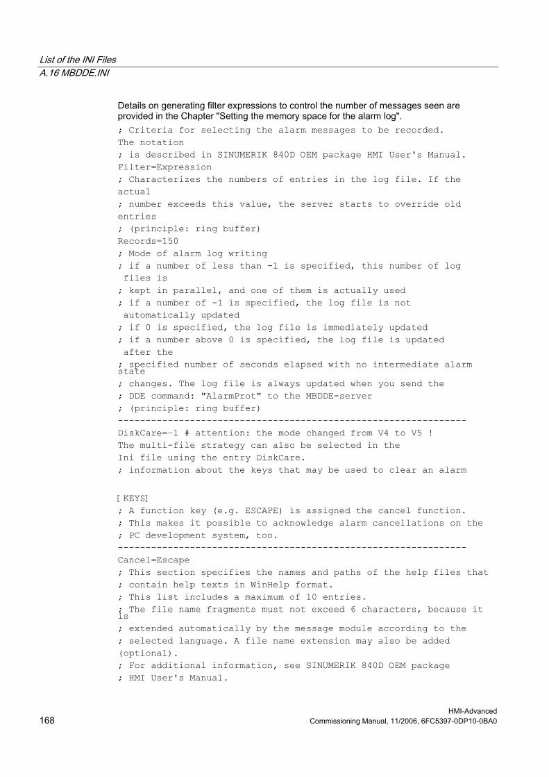
List of the INI Files A.16 MBDDE.INI
HMI-Advanced 168 Commissioning Manual, 11/2006, 6FC5397-0DP10-0BA0
Details on generating filter expressions to control the number of messages seen are provided in the Chapter "Setting the memory space for the alarm log". ; Criteria for selecting the alarm messages to be recorded. The notation ; is described in SINUMERIK 840D OEM package HMI User's Manual. Filter=Expression ; Characterizes the numbers of entries in the log file. If the actual ; number exceeds this value, the server starts to override old entries ; (principle: ring buffer) Records=150 ; Mode of alarm log writing ; if a number of less than -1 is specified, this number of log files is ; kept in parallel, and one of them is actually used ; if a number of -1 is specified, the log file is not automatically updated ; if 0 is specified, the log file is immediately updated ; if a number above 0 is specified, the log file is updated after the ; specified number of seconds elapsed with no intermediate alarm state ; changes. The log file is always updated when you send the ; DDE command: "AlarmProt" to the MBDDE-server ; (principle: ring buffer) --------------------------------------------------------------- DiskCare=−1 # attention: the mode changed from V4 to V5 ! The multi-file strategy can also be selected in the Ini file using the entry DiskCare. ; information about the keys that may be used to clear an alarm [KEYS] ; A function key (e.g. ESCAPE) is assigned the cancel function. ; This makes it possible to acknowledge alarm cancellations on the ; PC development system, too. --------------------------------------------------------------- Cancel=Escape ; This section specifies the names and paths of the help files that ; contain help texts in WinHelp format. ; This list includes a maximum of 10 entries. ; The file name fragments must not exceed 6 characters, because it is ; extended automatically by the message module according to the ; selected language. A file name extension may also be added (optional). ; For additional information, see SINUMERIK 840D OEM package ; HMI User's Manual.
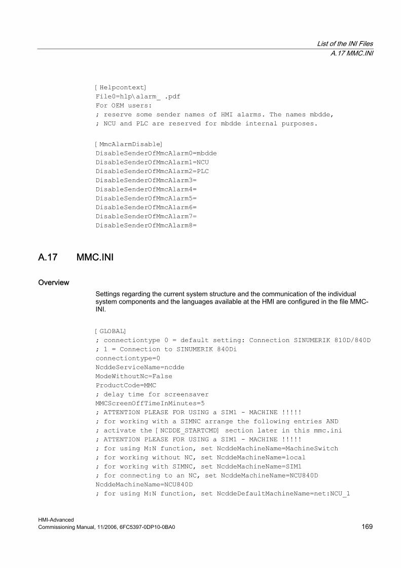
List of the INI Files A.17 MMC.INI
HMI-Advanced Commissioning Manual, 11/2006, 6FC5397-0DP10-0BA0 169
[Helpcontext] File0=hlp\alarm_ .pdf For OEM users: ; reserve some sender names of HMI alarms. The names mbdde, ; NCU and PLC are reserved for mbdde internal purposes. [MmcAlarmDisable] DisableSenderOfMmcAlarm0=mbdde DisableSenderOfMmcAlarm1=NCU DisableSenderOfMmcAlarm2=PLC DisableSenderOfMmcAlarm3= DisableSenderOfMmcAlarm4= DisableSenderOfMmcAlarm5= DisableSenderOfMmcAlarm6= DisableSenderOfMmcAlarm7= DisableSenderOfMmcAlarm8=
A.17 MMC.INI
Overview Settings regarding the current system structure and the communication of the individual system components and the languages available at the HMI are configured in the file MMC-INI. [GLOBAL] ; connectiontype 0 = default setting: Connection SINUMERIK 810D/840D ; 1 = Connection to SINUMERIK 840Di connectiontype=0 NcddeServiceName=ncdde ModeWithoutNc=False ProductCode=MMC ; delay time for screensaver MMCScreenOffTimeInMinutes=5 ; ATTENTION PLEASE FOR USING a SIM1 - MACHINE !!!!! ; for working with a SIMNC arrange the following entries AND ; activate the [NCDDE_STARTCMD] section later in this mmc.ini ; ATTENTION PLEASE FOR USING a SIM1 - MACHINE !!!!! ; for using M:N function, set NcddeMachineName=MachineSwitch ; for working without NC, set NcddeMachineName=local ; for working with SIMNC, set NcddeMachineName=SIM1 ; for connecting to an NC, set NcddeMachineName=NCU840D NcddeMachineName=NCU840D ; for using M:N function, set NcddeDefaultMachineName=net:NCU_1
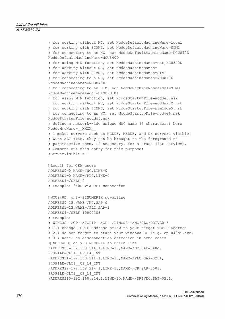
List of the INI Files A.17 MMC.INI
HMI-Advanced 170 Commissioning Manual, 11/2006, 6FC5397-0DP10-0BA0
; for working without NC, set NcddeDefaultMachineName=local ; for working with SIMNC, set NcddeDefaultMachineName=SIM1 ; for connecting to an NC, set NcddeDefaultMachineName=NCU840D NcddeDefaultMachineName=NCU840D ; for using M:N function, set NcddeMachineNames=net,NCU840D ; for working without NC, set NcddeMachineNames= ; for working with SIMNC, set NcddeMachineNames=SIM1 ; for connecting to a NC, set NcddeMachineNames=NCU840D NcddeMachineNames=NCU840D ; for connecting to an SIM, add NcddeMachineNamesAdd1=SIM0 NcddeMachineNamesAdd1=SIM0,SIM1 ; for using M:N function, set NcddeStartupFile=ncdde6.nsk ; for working without NC, set NcddeStartupFile=ncdde202.nsk ; for working with SIMNC, set NcddeStartupFile=sim1dde5.nsk ; for connecting to an NC, set NcddeStartupFile=ncdde6.nsk NcddeStartupFile=ncdde6.nsk ; define a network-wide unique MMC name (8 characters) here NcddeMmcName=__XXXX__ ; 1 makes servers such as NCDDE, MBDDE, and DH servers visible. ; With ALT +TAB, they can be brought to the foreground to ; parameterize them, if necessary, for a trace (for service). ; Comment out this entry for this purpose: ;ServerVisible = 1 [Local] for OEM users ADDRESS0=0,NAME=/NC,LINE=0 ADDRESS1=0,NAME=/PLC,LINE=0 ADDRESS4=/SELF,0 ; Example: 840D via OPI connection [NCU840D] only SINUMERIK powerline ADDRESS0=13,NAME=/NC,SAP=d ADDRESS1=13,NAME=/PLC,SAP=1 ADDRESS4=/SELF,10000103 ; Example: ; WINCOS-->CP-->TCPIP-->CP-->LINCOS-->NC/PLC/DRIVE0-5 ; 1.) change TCPIP-Address below to your target TCPIP-Address ; 2.) do not forget to start your windows CP (e.g. cp_840di.exe) ; 3.) note: no disconnection detection in some cases ;[NCU840D] only SINUMERIK solution line ;ADDRESS0=192.168.214.1,LINE=10,NAME=/NC,SAP=040d, PROFILE=CLT1__CP_L4_INT ;ADDRESS1=192.168.214.1,LINE=10,NAME=/PLC,SAP=0201, PROFILE=CLT1__CP_L4_INT ;ADDRESS2=192.168.214.1,LINE=10,NAME=/CP,SAP=0501, PROFILE=CLT1__CP_L4_INT ;ADDRESS10=192.168.214.1,LINE=10,NAME=/DRIVE0,SAP=0201,
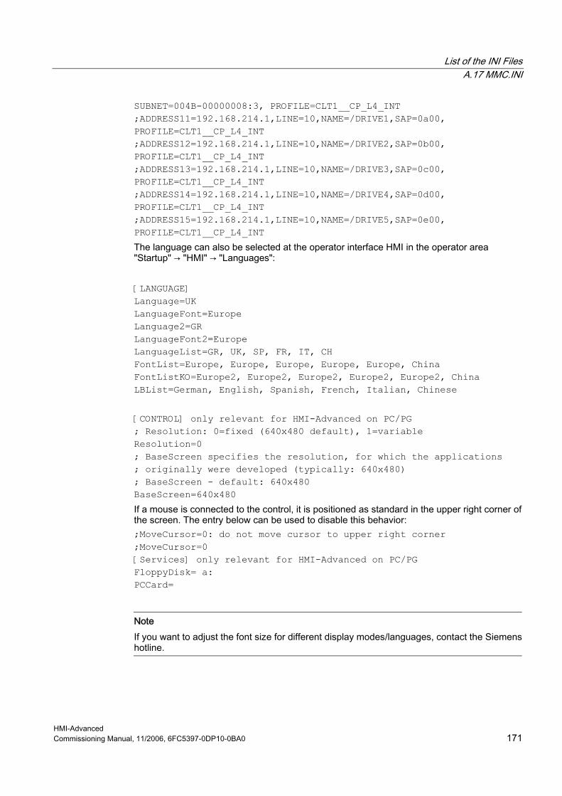
List of the INI Files A.17 MMC.INI
HMI-Advanced Commissioning Manual, 11/2006, 6FC5397-0DP10-0BA0 171
SUBNET=004B-00000008:3, PROFILE=CLT1__CP_L4_INT ;ADDRESS11=192.168.214.1,LINE=10,NAME=/DRIVE1,SAP=0a00, PROFILE=CLT1__CP_L4_INT ;ADDRESS12=192.168.214.1,LINE=10,NAME=/DRIVE2,SAP=0b00, PROFILE=CLT1__CP_L4_INT ;ADDRESS13=192.168.214.1,LINE=10,NAME=/DRIVE3,SAP=0c00, PROFILE=CLT1__CP_L4_INT ;ADDRESS14=192.168.214.1,LINE=10,NAME=/DRIVE4,SAP=0d00, PROFILE=CLT1__CP_L4_INT ;ADDRESS15=192.168.214.1,LINE=10,NAME=/DRIVE5,SAP=0e00, PROFILE=CLT1__CP_L4_INT The language can also be selected at the operator interface HMI in the operator area "Startup" → "HMI" → "Languages": [LANGUAGE] Language=UK LanguageFont=Europe Language2=GR LanguageFont2=Europe LanguageList=GR, UK, SP, FR, IT, CH FontList=Europe, Europe, Europe, Europe, Europe, China FontListKO=Europe2, Europe2, Europe2, Europe2, Europe2, China LBList=German, English, Spanish, French, Italian, Chinese [CONTROL] only relevant for HMI-Advanced on PC/PG ; Resolution: 0=fixed (640x480 default), 1=variable Resolution=0 ; BaseScreen specifies the resolution, for which the applications ; originally were developed (typically: 640x480) ; BaseScreen - default: 640x480 BaseScreen=640x480 If a mouse is connected to the control, it is positioned as standard in the upper right corner of the screen. The entry below can be used to disable this behavior: ;MoveCursor=0: do not move cursor to upper right corner ;MoveCursor=0 [Services] only relevant for HMI-Advanced on PC/PG FloppyDisk= a: PCCard=
Note If you want to adjust the font size for different display modes/languages, contact the Siemens hotline.

List of the INI Files A.17 MMC.INI
HMI-Advanced 172 Commissioning Manual, 11/2006, 6FC5397-0DP10-0BA0
The OPI settings are the display machine data that can also also be set for a specific technology using the operator interface of the HMI in the operator area "Start-up" → "Machine data": [OPI settings] $MM_LCD_CONTRAST=7 $MM_DISPLAY_TYPE = 1 $MM_DISPLAY_MODE = 2 $MM_FIRST_LANGUAGE = 1 $MM_DISPLAY_RESOLUTION=3 $MM_SPIND_DISPLAY_RESOLUTION=3 … $MM_MD_DRV_TEA_FILTER = 0 $MM_MD_DRV_TEA_IDX_LIMIT = 0 $MM_MD_TEXT_SWITCH=0 $MM_ACTION_LOG_MODE = 0xFE $MM_PROGRAM_SETTINGS = 0 $MM_SW_OPTIONS = 0 $MM_HMI_TESTAUTOMAT_OPTION = 0 $MM_HMI_WIZARD_OPTION = 0 $MM_TRACE=0 The action log can also be set using the operator interface of the HMI in the operator area "Start-up" → "HMI" → "System settings": ; ActionLog (action log) parameters [ActionLog] ; CommitLatency tells the maximum number of seconds that elapse before an ActionLog ; record is written to disk. If this value is less than 0 there is no ; time controlled automatic writing to disk at all ; Default : CommitLatency = -1 ; no automatic writing CommitLatency = -1 ; DirectoryPath specifies the directory of the log files DirectoryPath = D:\AC_LOG ; FileSize gives the upper size limit of the log file, in bytes FileSize = 40000 ; VariableN allows monitoring of max 10 NC/PLC variables. The first ; parameter is numeric and provides the monitoring mode: ; if Bit0 is set and the value of the variable changes, the value changes ; are logged in the ActionLog files ; if Bit1 is set and the value of the variable changes, the ActionLog files ; are committed to disk ; Default : Variable0 = 1, /Channel/ProgramInfo/msg ; monitor part program messages
List of the INI Files A.17 MMC.INI
HMI-Advanced Commissioning Manual, 11/2006, 6FC5397-0DP10-0BA0 173
Variable0 = 1, /Channel/ProgramInfo/msg ; CommittedAlarms holds up to 10 comma separated alarm numbers. ; Changes of these alarms commit ; ActionLog data to disk ; Default : CommittedAlarms = 3000 ; commit on emergency stop CommittedAlarms = 3000 ; for working with SIMNC, uncomment the following section descriptor ; this causes a sim-process to be started that will be used as a machine ;[NCDDE_STARTCMD] CMD=dpncsim.exe /T:1 /P:0 WND_CLASS=SIM_LOCAL_NCK WND_NAME=SIM_LOCAL_NCK STARTUP_TIMEOUT=50 ;WAIT_SYNC_MESSAGE= CLOSE_TIMEOUT=30 [WP_SELECT] ; for displaying a message that TOA/TMA-data on NCK will be overwritten ;TOA_WARNING_MESSAGE = yes/no TOA_WARNING_MESSAGE=yes [PCU] ; device name of PCU for USB local UsbFront=G: ' access rights of the PCU USB device (0-7) for the application machine, program and services AccessMachine=7 AccessProgram=7 AccessServices=7 [PROGRAM] ;0=message to user if a program of the DAT-file for MCSE was not found ; or a channel doesn't exist (default) ;1=skip all entries of DAT-file if the program or a channel was not found IgnoreMissingProgramAndChan=0 ;0=create a workpiece (optional by template) without opening by editor ;1=open part program, job list or DAT-file after creating ; new workpiece (default) OpenFileAfterNewWPD=1

List of the INI Files A.18 NETNAMES.INI
HMI-Advanced 174 Commissioning Manual, 11/2006, 6FC5397-0DP10-0BA0
The following is applicable to the multichannel sequence editor option in the USER directory: [PROGRAM] IgnoreMissingProgramAndChan=1 OpenFileAfterNewWPD=0 The "Channel assignment missing" message does not appear when workpieces are newly created using only a job list without MPF.
See also SEDITOR.INI (Page 180)
A.18 NETNAMES.INI
Overview In the file NETNAMES.INI, the m:n assignment is used to define which operator or operator components (TCU, PCU) can be connected with which NCU in the network. The following details are specified: • Name of the operator component • Name of the NCU • Communication connections between the NCUs • Unique assignments for booting References: Function Manual, Expansion Functions: Several operator panel fronts on several NCUs, distributed systems (B3)
Procedure It makes sense to maintain the following sequence when configuring NETNAMES.INI for m:n communication: 1. Copy the existing NETNAMES.BSP file created during installation, and modify it for the
application. 2. Rename the existing NETNAMES.INI file. 3. Rename the modified NETNAMES.BSP file to NETNAMES.INI. 4. Save under C:\USER\NETNAMES.INI. 5. Define groups (maximum of 24) in "logChanSetList" 6. Define the NCs and the channels with unique names for the groups in "logChanList". 7. For the channels, define the NC names in "logNCName", the channel number in the NC
in "ChanNum" and keep the softkey free yes/no (using the command IsAGap" = True/False).
8. For the HMI, specify the default machine "DEFAULT_logChanGrp" and the default channel in "DEFAULT_logChan" for booting.
List of the INI Files A.18 NETNAMES.INI
HMI-Advanced Commissioning Manual, 11/2006, 6FC5397-0DP10-0BA0 175
Note The NC writes the channel number of the HMI to DB19.DBB22. The example below is simplified for 1:1 assignment of HMI : NCU so that conn_2 is eliminated and all channels are located on NCU_1.
Example [own] owner = MMC_1 ; Description of possible connections [conn MMC_1] conn_1 = NCU_1 conn_2 = NCU_2 ; Description of significant net parameters [param network] bus = opi ; the MPI interface must be used on the SINUMERIK 810D [param MMC_1] mmc_address = 1 [param NCU_1] nck_address = 12 plc_address = 12 ; core name for the PLC symbol files for representing signals with symbols PlcSymbolFile= ... [param NCU_2] nck_address = 14 plc_address = 14 ; core name for the PLC symbol files for representing signals with symbols PlcSymbolFile= ... [chan MMC_1] DEFAULT_logChanGrp = Milling1 DEFAULT_logChan = Channel13 ShowChanMenu = TRUE logChanSetList = Milling1, Milling2
[Milling1]
List of the INI Files A.18 NETNAMES.INI
HMI-Advanced 176 Commissioning Manual, 11/2006, 6FC5397-0DP10-0BA0
logChanList = Channel11, Channel12, Channel13, Channel14, Channel15 [Channel11] ; logical channel logNCName = NCU_1 ; logical NCU designation, refer above ChanNum = 1 ; channel number within the NCU [Channel12] logNCName = NCU_1 ChanNum = 2 [Channel13] logNCName = NCU_1 ChanNum = 3 [Channel14] logNCName = NCU_1 ChanNum = 4 [Channel15] logNCName = NCU_1 ChanNum = 5 [Milling2] logChanList = Channel21, Channel22, Channel23, Channel24, Channel25 [Channel21] logNCName = NCU_2 ChanNum = 1 [Channel22] logNCName = NCU_2 ChanNum = 2 [Channel23] logNCName = NCU_2 ChanNum = 3 [Channel24] logNCName = NCU_2 ChanNum = 4 [Channel25] logNCName = NCU_2 ChanNum = 5
List of the INI Files A.19 OEMFRAME.INI
HMI-Advanced Commissioning Manual, 11/2006, 6FC5397-0DP10-0BA0 177
A.19 OEMFRAME.INI
Overview The starting behavior of OEM-applications is configured in the file OEMFRAME.INI. [SysMeter] ; let OEMFrame just look for Windows which have been ; created by the OEMApp ; default is 0 (means NO) ;fSearchOnlyForTaskWindow=1 ; let OEMFrame delay INIT_COMPLETE, if set to -1, ; OEMFrame will not send any WM_INITCOMPLETE at all, ; this value must be given in microseconds ;nDelayInitComplete=10000 ; switching WS_SYSMENU, WS_MINIMIZEBOX and WS_MAXIMIZEBOX off WindowStyle_Off = 720896 ; other possible task entries aren't used WindowStyle_On = x = y = Width = Height =
A.20 PARAM.INI
Overview The tool compensation data that the user enters via the HMI operator interface are input into this file. [ACCESSLEVEL] READ_SYSVAR=7 EDIT_VIEW=7 ;Tool compensation user data ;Tool-specific parameters [ToolParams] UserDataParamName1=T_Param_1 UserDataParamName2=T_Param_2 UserDataParamName3=T_Param_3 UserDataParamName4=T_Param_4 UserDataParamName5=T_Param_5 UserDataParamName6=T_Param_6 UserDataParamName7=T_Param_7 UserDataParamName8=T_Param_8 UserDataParamName9=T_Param_9
List of the INI Files A.21 PARAMTM.INI
HMI-Advanced 178 Commissioning Manual, 11/2006, 6FC5397-0DP10-0BA0
UserDataParamName10=T_Param_10 ; cutting edge-specific parameter [ToolEdgeParams] UserDataParamName1=D_Param_1 UserDataParamName2=D_Param_2 UserDataParamName3=D_Param_3 UserDataParamName4=D_Param_4 UserDataParamName5=D_Param_5 UserDataParamName6=D_Param_6 UserDataParamName7=D_Param_7 UserDataParamName8=D_Param_8 UserDataParamName9=D_Param_9 UserDataParamName10=D_Param_10 ; Tool compensation data
A.21 PARAMTM.INI
Overview All data that describe the operator interface of the tool manager are saved in the file ...\user\paramtm.ini. References: The extensive parameterizing possibilities are listed in the Function Manual Tool Manager.
A.22 REGIE.INI
Overview Settings to start and end the HMI application and the associated sub-systems are made in the file REGIE.INI. [Miscellaneous] ; needed if regie is to support an 'EXIT' button ; set 'ExitButton' to True, and 'ExitButtonIndex' ; identifies index of exit button ; The softkey text for this button MUST be entered into ; \mmc2\language\re_xx.ini ; where xx is the language-abbreviation e.g. : ; re_gr.ini (German text) ; re_uk.ini (English text) ExitButton = True ExitbuttonIndex = 15 ; Protection level for exit button
List of the INI Files A.22 REGIE.INI
HMI-Advanced Commissioning Manual, 11/2006, 6FC5397-0DP10-0BA0 179
ExitButtonAccessLevel = 7 ; Dialog box to ask user ExitButtonQueryUser = True ; Notes on other entries can be found in the OEM documentation ; Activating the temperature monitoring for PCU50 ; TemperatureMonitoring = True TemperatureMonitoring = False ; Default setting off Reference: OEM Package HMI
Hibernate (only for Windows XP) The parameter HibernateMode is in the section [Miscellaneous] to set the hibernate versions. These settings can also be made via the user interface of HMI-Advanced. To do this, select in the operator area "Start-up" → "HMI" → "System Settings". [Miscellaneous] HibernateMode = ... The following values can be set:
HibernateMode = Off Default: Off
Hibernate save and hibernate reboot operations are not performed.
HibernateMode = Normal HMI-Advance first closes all applications. After the shutdown, the control is restarted automatically.
HibernateMode = Advanced Not implemented ; Index of task started by the regie after power on ; (may differ in some circumstances from the default task index, ; which is the task index from [TaskConfiguration] with the lowest number. PoweronTaskIndex = 0 [StartupConfiguration] OEM software in the range from 12 to 24 can be started in this section. The [StartupConfiguration] section is subdivided as follows: 0 to 12 is reserved for expanded functionality provided by Siemens 12 to 24 free for OEM applications 25 to 32 reserved for simulation 33 to 47 reserved for Siemens applications (in the directory ADD_ON) Example: Startup33 = name := ITS, Timeout :=15000 Startup34 = name := HMIVers, Cmdline := "/StartUp", Timeout :=10000
List of the INI Files A.23 SEDITOR.INI
HMI-Advanced 180 Commissioning Manual, 11/2006, 6FC5397-0DP10-0BA0
[TaskConfiguration] ; 3. bar ; Task16 = name := oemframe, cmdline := "sysmeter", Timeout := 10000, ; ClassName := "SysMeter", HeaderOnTop := False, PreLoad := False The 3rd horizontal softkey bar is only displayed if, from task 16 onwards, a task or the EXIT button has been assigned to it. ; 4th bar : located to task 96 - 103 ;Task96 = name := oem, Timeout := 10000 ;Task97 = name := oem, Timeout := 10000 ;Task98 = name := oem, Timeout := 10000 ;Task99 = name := oem, Timeout := 10000 ;Task100 = name := oem, Timeout := 10000 ;Task101 = name := oem, Timeout := 10000 ;Task102 = name := oem, Timeout := 10000 ;Task103 = name := oem, Timeout := 10000 The 4th horizontal softkey bar is only displayed if, from task 96 onwards, a task or the EXIT button has been assigned to it. The task 50 to task 87 entries can be used by OEMs. [CommandToTask] ; only necessary for HMI invocation through NCU via command channel plc_select = #13 Cycles = #14 In this section, you can specify that the HMI will be started from the NCU via the command channel. References: Commissioning Manual "Supplement operator interface", Chapter "Activating the dialog screen from the NC program"
A.23 SEDITOR.INI
Overview You can modify the displays in the multi-channel step sequence programming (option) by making the appropriate settings or specific supplements in this file. The sections that contain the code [ *User* ] allow the cycles of the machinery construction OEM and the user to be identified as "steps" and display these. In addition, other details can be specified. To configure your own steps, settings can be made in the following sections:
[SyncMarks_User] Expansions to incorporate synchronization marks [USER_VARIABLES] Variables for channels with synchronization marks [Old_or_User_Cycles_USER] Expansions for user cycles; any variable names can be
entered here. [ProgSupport_User] Expansions to incorporate your own cycles

List of the INI Files A.23 SEDITOR.INI
HMI-Advanced Commissioning Manual, 11/2006, 6FC5397-0DP10-0BA0 181
The merge mechanism is used for the settings; this means that with respect to the standard version of the ini file, only changes and supplements have to be saved in this directories add_on, oem and user.
Syntax rules Note the following information regarding your expansions: ;************************************************************* ;The following rules must be used for the sections: ; - [SyncMarks_Siemens] [SyncMarks_User] ; - [Old_or_User_Cycles_Siemens] ; - [Old_or_User_Cycles_USER] ; ;- You can use either *- or ?-statements. ; Do not mix these placeholders: ; ; L1* -> OK ; L1?? -> OK ; L1?1* -> NOT OK !!! ; ;- ? is replaced with numbers from 0 to 9, so the step editor ; will find the following strings: ; ; L1? -> L10, L19, L15, but NOT L1A ; LB?? -> LB23, LB99, LB00, but NOT LB1A or LBd6 ; ;- You can use the ?-statement once per entry: ; L1? -> OK ; L1?? -> OK ; L23??? -> OK ; L2??3? -> NOT OK !!! ;************************************************************* [MISC] IconPath Relative path to the directory in which the icons are stored. The path is relative to ..\mmc2. The same directory can also be present in Add_on, oem, and user. The icons are also searched for in these directories. Default: IconPath = ae\skpicto EndIcon Icon for the last block. This icon must be located in the directory that was specified in IconPath. GCodeIcon Icon for free DINCode. This icon must be located in the directory that was specified in IconPath.
List of the INI Files A.23 SEDITOR.INI
HMI-Advanced 182 Commissioning Manual, 11/2006, 6FC5397-0DP10-0BA0
ShowBlockNumber Display of line number (e.g. N210). The number of the first line of a block is always displayed. 0: Line number is not displayed 1: Line number is displayed TimeFormat The displayed lines can be formatted in VB syntax, e.g. number of decimal places. ####0.000: Time display with 3 decimal places. CopySyncBuffers For the synchronized view, you can specify here whether or not the empty blocks that were inserted for synchronization will be copied. 0: Do not copy empty blocks 1: Copy empty blocks [INSERT] TemplateForNewBlock Using the key combination CTRL+I, in the edit mode, a step of an SEFORM instruction can be added. The text to be inserted can be configured here. [Cache] Enabled A file can be opened faster by using the cache. The individual data for the sequence view are stored separately and can be re-accessed, provided the part program has not been changed. Presently, only the following setting is available 0: Cache is not active 1: Cache is active [DefaultIcons] These icons are displayed if icons are not specified in the individual definitions, e.g. if an icon is not included in SEFORM(…). This icon must be located in the directory that was specified under IconPath. Block Icon for main step – SEFORM(…, 0, …) SubBlock Icon for sub-step – SEFORM(…, 1, …) Sync Icon for synchronization marks – e.g. WAITM(…) Cycle Icon for cycle GeoProz Icon for contour path [SyncMarks_User]

List of the INI Files A.23 SEDITOR.INI
HMI-Advanced Commissioning Manual, 11/2006, 6FC5397-0DP10-0BA0 183
Machine manufacturers can enter their expansions for synchronization marks here.
;Definition of synchronization marks (search texts) ;sync1 = WAITM*(*n,*c,*c,*c,*c,*c,*c,*c,*c,*c,*c) ; '#' : seperator: text before is searched in one ; channel, text behind in all others. ; It isn't possible to synchronize this kind of ; synchronization marks !!! ; '*n': identifier for synchronization numbers ; WAITM(*n,1,2,3) ; '*c': channel WAITM(1,*c,*c,*c), if own channel ; is missing, it will be added like WAITM-strategy ; ; Add additional / language dependent Text: ; WAITM*(*n,*c,*c,*c,*c,*c,*c,*c,*c,*c,*c) "$85000 The Text" ; ;sync1_Ico = clock.bmp ; belonging icon for defined sync mark ;sync1_Chans = 1,2,4 ; Project the channels to synchronize here ; e.g.: you have a M-function (M4711) ; to synchronize the channels 1, 2 and 4 ; Then you can write here: syncX=1,2,4 ; If you synchronize the part programs the ; channel 3 will not be considered. ; If you don't project anything here, in all ; channels must stand the M4711 call ; respective if there are *C in [SyncMarks] ; only these channels will be synchronized. ;SIEMENS [SyncMarks_Siemens] sync1 = WAITM*(*n,*c,*c,*c,*c,*c,*c,*c,*c,*c,*c) sync1_Ico = clock.bmp sync1_Chans = ;USER [SyncMarks_User]
sync1 Definition of search string. The following syntax applies: * space holder; text in '*' must be the same in all channels. n identification using a number e.g. WAITM(*n,1,2,3) Wait marks can be assigned using this number. *c channel number, these do not have to be in the same sequence, the separate channel does not have to be specified (e.g: WAITM(1,*c,*c,*c). # Channel separator character: Text in front of the separator character is searched for in a channel, the text is then searched in all others. These synchronization marks cannot be synchronized with one another. sync1_Ico Associated icon, it must be located in the directory that was specified in IconPath. sync1_Chans
List of the INI Files A.23 SEDITOR.INI
HMI-Advanced 184 Commissioning Manual, 11/2006, 6FC5397-0DP10-0BA0
Here, it can be specified whether the associated synchronization marks will be searched for in certain channels only. If no entry is made, the search will be carried out in all channels or in those that are specified if *c was configured. Example: M4711 is a synchronization that only acts on Channels 1, 2, and 6. The entry must then look like this: sync2 = M4711 sync2_Ico = clock.bmp sync2_Chans = 1,2,6 [Old_or_User_Cycles_User] Machine manufacturers can enter their expansions for their own cycles here. Examples: Cycle1 = Cycle* Cycle1_Type = 1 Cycle1_Ico = cycle.bmp Cycle2 = Pocket* Cycle2_Type = 1 Cycle2_Ico = cycle.bmp ... CycleX Definition of cycles without graphical support. Subprogram calls can also be entered here. A language-specific text can also be specified. X stands for a cycle number, which must be the same over three associated entries.
Syntax: CycleX = L100(* CycleX = L100(* "$85001"
The following is displayed, e.g. "L100(2,3,4)" Language-dependent text that is stored in 85001.
CycleX = L100(* "$85001/fixed Text"
Language-dependent text that is saved in 85001 + "/fixed text"
CycleX_Type Definition of whether cycle is to be displayed as a subblock or a main block. 1: Sub-block 0: Main block CycleX_Ico Associated icon, it must be located in the directory that was specified in IconPath. [ProgSupport_User] Machine manufacturers can enter their expansions for their own cycles here. Example: ;Programming Support - Siemens Standard [ProgSupport_Siemens] NCG_1=CYC82 NCG_2=CYC86
List of the INI Files A.23 SEDITOR.INI
HMI-Advanced Commissioning Manual, 11/2006, 6FC5397-0DP10-0BA0 185
NCG_3=CYC83 NCG_4=CYC84 NCG_5=CYC84_1 NCG_6=CYC840_1 NCG_7=HOL1 NCG_8=HOL2 NCG_9=POS1 NCG_10=WPOS ... ;drilling [CYC82] ;drilling NCG_1_Label=NC1 NCG_1_Text=$80854 NCG_1_Ico=cm_poly_dr_drill.bmp NCG_1_Level=0 NCG_2_Label=NC2 NCG_2_Text=$80855 NCG_2_Ico=cm_poly_dr_drill.bmp NCG_2_Level=0 ;reaming NCG_3_Label=NC3 NCG_3_Text=$80853 NCG_3_Ico=cm_poly_dr_reaming.bmp NCG_3_Level=0 NCG_4_Label=NC4 NCG_4_Text=$80852 NCG_4_Ico=cm_poly_dr_reaming.bmp NCG_4_Level=0 … [CYC86] ;boring NCG_1_Label=NC1 NCG_1_Text=$80666 NCG_1_Ico=cm_poly_dr_bore.bmp NCG_1_Level=0 NCG_2_Label=NC2 NCG_2_Text=MCALL CYCLE86 NCG_2_Ico=cm_poly_dr_bore.bmp NCG_2_Level=0 [CYC83] ;deep hole drilling NCG_1_Label=NC1
List of the INI Files A.23 SEDITOR.INI
HMI-Advanced 186 Commissioning Manual, 11/2006, 6FC5397-0DP10-0BA0
NCG_1_Text=$80794 NCG_1_Ico=cm_poly_dr_deepdrill.bmp NCG_1_Level=0 NCG_2_Label=NC2 NCG_2_Text=MCALL CYCLE83 NCG_2_Ico=cm_poly_dr_deepdrill.bmp NCG_2_Level=0
Explanations: As example, two graphically-supported cycles are shown here. The following lines appear in place of the cycle in the NC program: ;NCG#CYC82#\CST.DIR\bohren.com#NC1#2#*NCG;*RO*;*HD* ;#1#1#1#1#1###"M3"####1##1#*NCG;*RO*;*HD* CYCLE82(1,2,3,4,,0) ;#END#*NCG;*RO*;*HD* [ProgSupport_User] No. Here, the number of the following entries must be specified. NCG_1 Entries of individual search texts or name of cycles. Generally, this is the text that is located in the NC program after ";NCG#". In the example above, this would be "CYC82". Because there can be several versions (e.g. NC1, NC2, etc.) for such a cycle, an additional section must be set-up in the INI file for this entry [CYC82]. Section for cycles (e.g.: [CYC82]) No. Number of cycle versions. NCG_1_Label "Name" if the version. Generally, this is the text that is found in the NC program after the path of the COM file (NC1, NC2, ...). NCG_1_Text Text that is displayed. A fixed text, a language-specific text ($85111), or a combination of both ($85111/my additional text) can be specified. NCG_1_Ico Associated icon, it must be located in the directory that was specified in IconPath. NCG_1_Level Definition of whether cycle is to be displayed as a subblock or a main block. 1: Sub-block 0: Main block References: Commissioning Manual "Supplement operator interface"
List of the INI Files A.24 SIMTOGEO.INI
HMI-Advanced Commissioning Manual, 11/2006, 6FC5397-0DP10-0BA0 187
A.24 SIMTOGEO.INI
Overview Sample file with the details required for simulation for the individual tool types.
Note If Link is set to 0 in the [Settings] section, the other entries in SIMTOGEO.INI are redundant.
[SETTINGS] ; this entry is dependent on settings such as ; ; MD 18206: $MN_MM_NUM_CCS_TOA_PARAM=1 ; MD 18207: $MN_MM_TYPE_CCS_TOA_PARAM[1]=4 ; MD 18080: $MN_MM_TOOL_MANAGEMENT_MASK='H4' ; ; if required and / or if other oem parameters are used, the index can be changed ; ( e.g. TC_DPCS4 if $MN_MM_NUM_CCS_TOA_PARAM=4 ) ; or any other oem variable than TC_DPCS1 can be used : ; ;LINK=TC_DPC7 ; ; MD 18096: $MN_MM_NUM_CC_TOA_PARAM=7 ; MD 18097: $MN_MM_TYPE_CC_TOA_PARAM[7]=4 ; MD 18080: $MN_MM_TOOL_MANAGEMENT_MASK='H4' ; LINK=0 ; example LINK=TC_DPCS1 ; example data sets [500.1] ; Unique identifier (t,d) for roughing tool 1 tool_type=500 ; tool type, if not set, $TC_DP1 is ; used insert_length= ; TC_DP8, plate length holder_angle= ; TC_DP10, holder angle reference_direction= ; TC_DP11, cutting direction clearance_angle= ; TC_DP24, clearance angle [500.2] ; Unique identifier (t,d) for finishing tool 1 tool_type=510 ; tool type, if not set, $TC_DP1 is ; used insert_length= ; TC_DP8, plate length holder_angle= ; TC_DP10, holder angle reference_direction= ; TC_DP11, cutting direction clearance_angle= ; TC_DP24, clearance angle

List of the INI Files A.24 SIMTOGEO.INI
HMI-Advanced 188 Commissioning Manual, 11/2006, 6FC5397-0DP10-0BA0
[520.1] ; Unique identifier (t,d) for plunging tool 1 tool_type=520 ; tool type, if not set, $TC_DP1 is used insert_length= ; TC_DP8, plate length reference_direction= ; TC_DP11, cutting direction [530.1] ; Unique identifier (t,d) for parting tool 1 tool_type=530 ; tool type, if not set, $TC_DP1 is used insert_length= ; TC_DP8, plate length reference_direction= ; TC_DP11, cutting direction [540.1] ; Unique identifier (t,d) for thread-cutting tool 1 tool_type=540 ; tool type, if not set, $TC_DP1 is used reference_direction= ; TC_DP11, cutting direction [160.1] ; Unique identifier (t,d) for boring-threading-milling cutter tool_type=160 ; tool type, if not set, $TC_DP1 is used tip_angle= ; TC_DP10, tip angle ;TC_DPV3= ; 1=+X; -1=-X ;TC_DPV4= ; 1=+Y; -1=-Y ;TC_DPV5= ; 1=+Z; -1=-Z [151.1] ; Unique identifier (t,d) for saw tool_type=151 ; tool type, if not set, $TC_DP1 is ; used width= ; TC_DP9, width ;TC_DPV3= ; 1=+X; -1=-X ;TC_DPV4= ; 1=+Y; -1=-Y ;TC_DPV5= ; 1=+Z; -1=-Z ;data set for tool_types 200-299 [200.001] ; Unique identifier (t,d) tool_type= ; tool type, if not set, $TC_DP1 is used tip_angle= ; TC_DP24, tip angle ;TC_DPV3= ; 1=+X; -1=-X ;TC_DPV4= ; 1=+Y; -1=-Y ;TC_DPV5= ; 1=+Z; -1=-Z ; default tool data sets reserved by SIEMENS AG for later use ; default data sets are recognized by non digit values ; examples ;[500] ; number corresponding to tool type, roughing tool ;insert_length= ; TC_DP8, plate length ;holder_angle= ; TC_DP10, holder angle ;reference_direction= ; TC_DP11, cutting direction ;clearance_angle= ; TC_DP24, clearance angle

List of the INI Files A.25 TASKCONF.INI
HMI-Advanced Commissioning Manual, 11/2006, 6FC5397-0DP10-0BA0 189
;[510] ; number corresponding to tool type, finishing tool ;insert_length= ; TC_DP8, plate length ;holder_angle= ; TC_DP10, holder angle ;reference_direction= ; TC_DP11, cutting direction ;clearance_angle= ; TC_DP24, clearance angle
A.25 TASKCONF.INI
Overview Softkeys and softkey bars for user-specific operator areas are configured in the file TASKCONF.INI. [CONTROL] MDIList=MntMMC\MntMMC.mdi ControlFile=MntMMC\MntMMC.zus ScreenTwips=1 [DEBUG] ;MDISize 0 = Debug, 1 = Full screen MDISize=0 ;Buttons: 0 = button invisible, 1 = button visible Stop_Button=1 ; Here you can configure a skeleton application. Set instead ; APPLICATION, the section name configured in regie.ini. ; For every section name in regie.ini with ; Task i = name:= mntmmc cmdLine:= "SektionName", ... assigned ; section names must be configured here for an autonomous section. [APPLICATION] ; HSK1.. - HSK8.. (horizontal softkeys) ; HSK9.. - HSK16.. (ETC softkeys) ; VSK1.. - VSK8.. (vertical softkeys) ; background picture (default : none) ; 1 : machine configuration ; <filename> : load bitmap from OEM directory Picture= ; index [1,.. initial application (default : none) StartIndex= ; 0 : permanent task (default) ; <> 0 : terminate task at recall TerminateTask= ;=================================================; ; for each softkey (HSK1 - HSK16 / VSK1 - VSK8) ; ;=================================================;
List of the INI Files A.25 TASKCONF.INI
HMI-Advanced 190 Commissioning Manual, 11/2006, 6FC5397-0DP10-0BA0
; taskid (see regie.ini) or logical task name (program/<root> or ExitButton) ; !!! ExitButton, display button for shutdown of HMI-Adv !!! HSK1Task= ; 0 : recall to calling process (default) ; <> 0 : terminate application at recall (appends ;TerminateTask to HSK1Command) ; must be supported by application ! HSK1TerminateTask= ; 0 : SwitchToChild (default) ; 1 : SwitchToTask -> switch only to task ; 2 : SwitchToTask2 -> switch to child of specified task (if it exists) HSK1IsTask= ; command string evaluated by application (default : empty) HSK1Command= ; access level for softkey (0 - 7, default : 7) HSK1AccessLevel= ; 0 : no link to NCK ; <> 0 : link softkey to NCK (lock softkey while no connection to NCK) HSK1NckLink= ; default softkey text, ignored for logical task name HSK1SkText= ; language depending softkey text, ignored for logical task name HSK1SkText_GR= HSK1SkText_UK=
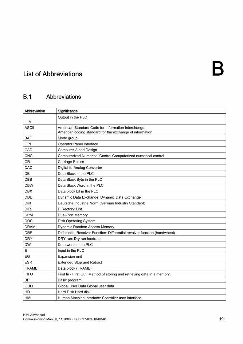
HMI-Advanced Commissioning Manual, 11/2006, 6FC5397-0DP10-0BA0 191
List of Abbreviations BB.1 Abbreviations Abbreviation Significance A
Output in the PLC
ASCII American Standard Code for Information Interchange American coding standard for the exchange of information
BAG Mode group OPI Operator Panel Interface CAD Computer-Aided Design CNC Computerized Numerical Control Computerized numerical control CR Carriage Return DAC Digital-to-Analog Converter DB Data Block in the PLC DBB Data Block Byte in the PLC DBW Data Block Word in the PLC DBX Data block bit in the PLC DDE Dynamic Data Exchange: Dynamic Data Exchange DIN Deutsche Industrie Norm (German Industry Standard) DIR DIRectory: List DPM Dual-Port Memory DOS Disk Operating System DRAM Dynamic Random Access Memory DRF Differential Resolver Function: Differential revolver function (handwheel) DRY DRY run: Dry run feedrate DW Data word in the PLC E Input in the PLC EG Expansion unit ESR Extended Stop and Retract FRAME Data block (FRAME) FIFO First In - First Out: Method of storing and retrieving data in a memory. BP Basic program GUD Global User Data Global user data HD Hard Disk Hard disk HMI Human Machine Interface: Controller user interface

List of Abbreviations B.1 Abbreviations
HMI-Advanced 192 Commissioning Manual, 11/2006, 6FC5397-0DP10-0BA0
Abbreviation Significance MSD Main Spindle Drive Hardware Hardware IBN Commissioning ICA Interpolatory Compensation Interpolatory compensation INC Increment: Increment INI INItializing data Initializing data IPO Interpolator ISO International Standard Organization JOG JOGging: Setup mode K1 .. C4 Channel 1 to channel 4 LED Light-Emitting Diode: Light-emitting diode LF Line Feed Kv Servo gain factor LUD Local User Data: Local user data MB Megabyte MCP Machine Control Panel Machine control panel (→ MCP) MD Machine data MDI Manual Data Input: Manual input MCS Machine coordinate system MLFB Machine-readable product designation MPF Main Program File: NC part program (main program) MPI Multi-Point Interface Multiport Interface MCP Machine control panel NC Numerical Control: Numerical control NCK Numerical Control Kernel: NC kernel with block preparation, traversing range, etc. NCU Numerical Control Unit: NCK hardware unit ZO Zero point shift OEM Original Equipment Manufacturer OP Operator Panel: Operating equipment PCU Programmable Control Unit PCMCIA Personal Computer Memory Card International Association: Standardization for memory cards PG Programming device PLC Programmable Logic Control: REF REFerence point approach function REPOS REPOSition function ROV Rapid Override: Input correction RPA R-Parameter Active: Memory area on the NCK for R parameter numbers SBL Single Block: Single BLock SD Setting Data SDB System Data Block SEA Setting Data Active: Identifier (file type) for setting data SK Softkey

List of Abbreviations B.1 Abbreviations
HMI-Advanced Commissioning Manual, 11/2006, 6FC5397-0DP10-0BA0 193
Abbreviation Significance SKP SKiP: Skip block SPF SubProgram File: Subprogram SRAM Static RAM (non-volatile) GWPS Grinding wheel surface speed SW Software SYF SYstem Files System files TEA Testing Data Active: Identifier for machine data TO Tool Offset Tool offset TOA Tool Offset Active: Identifier (file type) for tool offsets UFR User frame FD Feed Drive WCS Workpiece coordinate system TO Tool offset TC Tool change ZOA Zero Offset Active: Identifier (file type) for work offset data

List of Abbreviations B.1 Abbreviations
HMI-Advanced 194 Commissioning Manual, 11/2006, 6FC5397-0DP10-0BA0

HMI-Advanced Commissioning Manual, 11/2006, 6FC5397-0DP10-0BA0 195
Index
A Access authorizations
Basic offset, 81 Changing default setting, 25 Drives, 48
Acknowledgement mechanism, 94 Action log, 126
Setting, 126 Activating data transfer, 90 AEDITOR.INI, 143 Alarms
Numbers, 62 Setting the log, 22
ANSI tables/fonts, 63 Axes
Displaying selected, 124 Hiding, 81
B Behavior of the keyboard, 12 Block search, 98 Boot
Simulation, 57
C CAPSLOCK, 12 Configuring OEM icons, 107 Configuring OEM texts, 106, 151 Configuring the screensaver, 21 Creating alarm texts, 65 Creating an operator menu, 27 Cycles
Match, 55 save in the DRAM, 78
D Data management (DH), 14 Data match of the simulation, 54
Data transfer from the PLC, 89 Data transfer TCU, 51 Definition files, 80 Desktop switch, 111 DG.INI, 145 DGOVW.INI, 146 DGOVWTXT.INI, 146 DH.INI, 147 DINO.INI, 144 Display
Messages in header, 94 Simulation data, 53
Display filter, 70 Displaying server names, 21 Displaying the spindle utilization, 83 Displaying versions, 115 Double-channel display, 40 DPDH.INI, 147 DPSIM.INI, 58, 147 Drives
Connecting via MD, 46 Setting screen, 49
E Error code, 94 Error messages to the PLC, 91 EXTCALL, 45
F Filter for alarms, 23 Flash File System (FFS), 79 Flying edge, 58
H HEADER.INI, 148 HMI
Configuring, 21 Functions, 69 Settings, 8
HMI Analyzer Analyzing data, 135
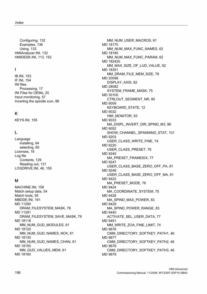
Index
HMI-Advanced 196 Commissioning Manual, 11/2006, 6FC5397-0DP10-0BA0
Configuring, 132 Examples, 136 Using, 133
HMIAnalyzer.INI, 132 HMIDESK.INI, 113, 152
I IB.INI, 153 IF.INI, 154 INI files
Processing, 17 INI Files for OEMs, 20 Input monitoring, 57 Inverting the spindle icon, 86
K KEYS.INI, 155
L Language
installing, 64 selecting, 65
Licenses, 16 Log file
Contents, 129 Reading out, 131
LOGDRIVE.INI, 46, 155
M MACHINE.INI, 158 Match setup data, 54 Match tools, 55 MBDDE.INI, 161 MD 11290
DRAM_FILESYSTEM_MASK, 78 MD 11291
DRAM_FILESYSTEM_SAVE_MASK, 79 MD 18118
MM_NUM_GUD_MODULES, 61 MD 18120
MM_NUM_GUD_NAMES_NCK, 61 MD 18130
MM_NUM_GUD_NAMES_CHAN, 61 MD 18150
MM_GUD_VALUES_MEM, 61 MD 18160
MM_NUM_USER_MACROS, 61 MD 18170
MM_NUM_MAX_FUNC_NAMES, 62 MD 18180
MM_NUM_MAX_FUNC_PARAM, 62 MD 182420
MM_MAX_SIZE_OF_LUD_VALUE, 62 MD 18351
MM_DRAM_FILE_MEM_SIZE, 78 MD 20098
DISPLAY_AXIS, 82 MD 28082
SYSTEM_FRAME_MASK, 75 MD 30100
CTRLOUT_SEGMENT_NR, 80 MD 9009
KEYBOARD_STATE, 12 MD 9032
HMI_MONITOR, 93 MD 9033
MA_DISPL_INVERT_DIR_SPIND_M3, 86 MD 9052
SHOW_CHANNEL_SPANNING_STAT, 101 MD 9203
USER_CLASS_WRITE_FINE, 74 MD 9220
USER_CLASS_PRESET, 76 MD 9245
MA_PRESET_FRAMEIDX, 77 MD 9247
USER_CLASS_BASE_ZERO_OFF_PA, 81 MD 9248
USER_CLASS_BASE_ZERO_OFF_MA, 81 MD 9422
MA_PRESET_MODE, 76 MD 9424
MA_COORDINATE_SYSTEM, 75 MD 9428
MA_SPIND_MAX_POWER, 83 MD 9429
MA_SPIND_POWER_RANGE, 83 MD 9440
ACTIVATE_SEL_USER_DATA, 77 MD 9451
MM_WRITE_ZOA_FINE_LIMIT, 74 MD 9676
CMM_DIRECTORY_SOFTKEY_PATH1, 46 MD 9677
CMM_DIRECTORY_SOFTKEY_PATH2, 46 MD 9678
CMM_DIRECTORY_SOFTKEY_PATH3, 46 MD 9679

Index
HMI-Advanced Commissioning Manual, 11/2006, 6FC5397-0DP10-0BA0 197
CMM_DIRECTORY_SOFTKEY_PATH4, 47 Memory size
DRAM, 78 MMC.INI, 165 Multi-channel step sequence programming, 169, 176 Multiple file strategy, 23
N NC commands, 81 NCU Connection Wizard, 110 NCU link, 8 NETNAMES.INI, 44, 170
O OEM commissioning, 20 OEMFRAME.INI, 172 Operating messages (PLC), 86 Operator focus TCU, 51 Optimizing, 57
P PARAM.INI, 173 PARAMTM.INI, 174 Plain text for MD, 86 PLC
Acknowledging alarms, 24 Channel selection, 93 Machine data, 86 Programming, 89 Spindle selection, 93
PRESET, 75 Program test, 97 Prompt dialog box, 22 Protection levels
Concept, 13 NC commands, 81 NC data, 79
R REGIE.INI, 174
Hibernate, 175 HMI boot, 58 Request NEW START, 22
Rotary axis position, 77 Rotating the coordinate system, 56
S Scratching, 75 SEDITOR.INI, 176 Selecting the technology, 37 Series commissioning, 116 Service axis, 124 Service displays, 123 Service overview
Supplementing, 34 Set actual value, 75 SimNCK, 58 SIMTOGEO.INI, 59, 183 Simulation
Coordinate system, 56 Data, 52 Match cycles, 55 Match MDs, 55 Match setup data, 54 Match tools, 55 Mirroring tools, 56
Softkey "Language Selection", 26 Softkey labels, 47 Softkey 'USB local', 49 STAT (machine position), 77 State when supplied, 7 Status display with icons, 99, 104 System limits, 14 System resources, 125 System settings, 10
T TASKCONFIG.INI, 185 Templates, 39 Tool center point path, 57 Tool management (WZV), 41 Tool offset, 77 Tool selection without tool management, 43 TU (rotary axis position), 77
U User control file, 90 User views, 72
W Work offset, fine, 74 Workpieces with job lists, 39

Index
HMI-Advanced 198 Commissioning Manual, 11/2006, 6FC5397-0DP10-0BA0

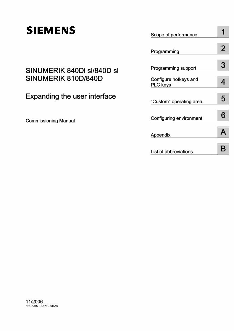
SINUMERIK 840Di sl/840D sl SINUMERIK 810D/840D SINUMERIK Expanding the user interface __________________________________________
____________________________
__________________________________________
Scope of performance 1
Programming 2
Programming support 3
Configure hotkeys and PLC keys
4
"Custom" operating area 5
Configuring environment 6
Appendix A
List of abbreviations B
SINUMERIK 840Di sl/840D sl SINUMERIK 810D/840D SINUMERIK Expanding the user interface
Commissioning Manual
11/2006 6FC5397-0DP10-0BA0

Safety Guidelines This manual contains notices you have to observe in order to ensure your personal safety, as well as to prevent damage to property. The notices referring to your personal safety are highlighted in the manual by a safety alert symbol, notices referring only to property damage have no safety alert symbol. These notices shown below are graded according to the degree of danger.
Danger
indicates that death or severe personal injury will result if proper precautions are not taken.
Warning
indicates that death or severe personal injury may result if proper precautions are not taken.
Caution
with a safety alert symbol, indicates that minor personal injury can result if proper precautions are not taken.
Caution
without a safety alert symbol, indicates that property damage can result if proper precautions are not taken.
Notice
indicates that an unintended result or situation can occur if the corresponding information is not taken into account.
If more than one degree of danger is present, the warning notice representing the highest degree of danger will be used. A notice warning of injury to persons with a safety alert symbol may also include a warning relating to property damage.
Qualified Personnel The device/system may only be set up and used in conjunction with this documentation. Commissioning and operation of a device/system may only be performed by qualified personnel. Within the context of the safety notes in this documentation qualified persons are defined as persons who are authorized to commission, ground and label devices, systems and circuits in accordance with established safety practices and standards.
Prescribed Usage Note the following:
Warning
This device may only be used for the applications described in the catalog or the technical description and only in connection with devices or components from other manufacturers which have been approved or recommended by Siemens. Correct, reliable operation of the product requires proper transport, storage, positioning and assembly as well as careful operation and maintenance.
Trademarks All names identified by ® are registered trademarks of the Siemens AG. The remaining trademarks in this publication may be trademarks whose use by third parties for their own purposes could violate the rights of the owner.
Disclaimer of Liability We have reviewed the contents of this publication to ensure consistency with the hardware and software described. Since variance cannot be precluded entirely, we cannot guarantee full consistency. However, the information in this publication is reviewed regularly and any necessary corrections are included in subsequent editions.
Siemens AG Automation and Drives Postfach 48 48 90437 NÜRNBERG GERMANY
Order No.: 6FC5397-0DP10-0BA0 Edition 10/2006
Copyright © Siemens AG 2006. Technical data subject to change
Expanding the user interface Commissioning Manual, 11/2006, 6FC5397-0DP10-0BA0 iii
Table of contents 1 Scope of performance ............................................................................................................................ 1-1 2 Programming .......................................................................................................................................... 2-1
2.1 Getting started............................................................................................................................ 2-1 2.1.1 Fundamentals of Configuration.................................................................................................. 2-1 2.1.2 Configuration and start files ....................................................................................................... 2-2 2.1.3 Structure of configuration file ..................................................................................................... 2-3 2.1.4 Troubleshooting (log book) ........................................................................................................ 2-4 2.2 Structure and elements of a dialog ............................................................................................ 2-6 2.2.1 Defining a dialog ........................................................................................................................ 2-6 2.2.2 Example Opening the Dialog ..................................................................................................... 2-8 2.2.3 Dialog properties...................................................................................................................... 2-10 2.2.4 Dialog elements ....................................................................................................................... 2-13 2.2.5 Dialogs with multiple columns.................................................................................................. 2-15 2.2.6 Unifying the dialog appearance ............................................................................................... 2-15 2.2.7 Using display images/graphics ................................................................................................ 2-17 2.3 Variables .................................................................................................................................. 2-19 2.3.1 Variable properties................................................................................................................... 2-19 2.3.2 Programming variables ............................................................................................................ 2-21 2.3.3 Detailed information about the variable type [1] ...................................................................... 2-24 2.3.4 Detailed information about the toggle field [2] ......................................................................... 2-27 2.3.5 Detailed information about the default setting [3] .................................................................... 2-28 2.3.6 Detailed information about the position of the short text [8] and position of the input/output
field [9]...................................................................................................................................... 2-29 2.3.7 Detailed information about on Help [11] (HMI-Advanced only) ............................................... 2-29 2.3.8 Application examples ............................................................................................................... 2-30 2.3.9 Example 1: Assigning the Variable Type, Texts, Help, Colors properties ............................... 2-31 2.3.10 Example 2: Assigning the Variable Type, Limits, Attributes, Short Text Position properties .. 2-32 2.3.11 Example 3: Assigning the Variable Type, Default, System or User Variable, Input/Output
Field Position properties .......................................................................................................... 2-33 2.3.12 Examples relating to toggle field, Help call and image display................................................ 2-33 2.3.13 Use of strings ........................................................................................................................... 2-35 2.3.14 CURPOS variable .................................................................................................................... 2-36 2.3.15 CURVER variable .................................................................................................................... 2-37 2.3.16 ENTRY variable ....................................................................................................................... 2-38 2.3.17 ERR variable............................................................................................................................ 2-39 2.3.18 FILE_ERR variable .................................................................................................................. 2-40 2.3.19 FOC variable............................................................................................................................ 2-41 2.3.20 S_CHAN variable ..................................................................................................................... 2-42 2.4 Complex dialog elements......................................................................................................... 2-42 2.4.1 Array......................................................................................................................................... 2-42 2.4.2 Accessing the value of an array element................................................................................. 2-43 2.4.3 Example Access to an array element ...................................................................................... 2-45 2.4.4 Scanning the status of an array element ................................................................................. 2-47 2.4.5 Table grid (grid)........................................................................................................................ 2-47 2.4.6 Defining table grids .................................................................................................................. 2-49

Table of contents
Expanding the user interface iv Commissioning Manual, 11/2006, 6FC5397-0DP10-0BA0
2.4.7 Defining columns...................................................................................................................... 2-49 2.4.8 Focus control in the table grid.................................................................................................. 2-51 2.4.9 Example Defining columns....................................................................................................... 2-52 2.4.10 Example Loading different table grids...................................................................................... 2-53 2.5 Softkey menus ......................................................................................................................... 2-55 2.5.1 Softkey description................................................................................................................... 2-55 2.5.2 Define softkey menu ................................................................................................................ 2-55 2.5.3 Changing softkey properties during runtime ............................................................................ 2-58 2.5.4 Defining the start softkey.......................................................................................................... 2-60 2.5.5 Functions for start softkeys ...................................................................................................... 2-60 2.6 Methods.................................................................................................................................... 2-62 2.6.1 CHANGE.................................................................................................................................. 2-62 2.6.2 FOCUS..................................................................................................................................... 2-64 2.6.3 LOAD GRID ............................................................................................................................. 2-64 2.6.4 LOAD........................................................................................................................................ 2-65 2.6.5 UNLOAD .................................................................................................................................. 2-66 2.6.6 OUTPUT................................................................................................................................... 2-66 2.6.7 PRESS ..................................................................................................................................... 2-67 2.6.8 Example Version management with OUTPUT blocks ............................................................. 2-68 2.7 Functions.................................................................................................................................. 2-70 2.7.1 Activate Program (AP) ............................................................................................................. 2-71 2.7.2 Define block (//B)...................................................................................................................... 2-72 2.7.3 Subprogram call (CALL)........................................................................................................... 2-73 2.7.4 Check Variable (CVAR) ........................................................................................................... 2-74 2.7.5 Copy Program (CP).................................................................................................................. 2-75 2.7.6 Dialog line (DLGL).................................................................................................................... 2-75 2.7.7 Delete Program (DP)................................................................................................................ 2-76 2.7.8 Evaluate (EVAL)....................................................................................................................... 2-77 2.7.9 Execute (EXE).......................................................................................................................... 2-78 2.7.10 Exist Program (EP) .................................................................................................................. 2-79 2.7.11 Exit dialog (EXIT) ..................................................................................................................... 2-80 2.7.12 Exit Loading Softkey (EXITLS) ................................................................................................ 2-81 2.7.13 Generate code (GC)................................................................................................................. 2-82 2.7.14 Load Array (LA)........................................................................................................................ 2-85 2.7.15 Load Block (LB)........................................................................................................................ 2-86 2.7.16 Load Mask (LM) ....................................................................................................................... 2-87 2.7.17 Load Softkey (LS) .................................................................................................................... 2-88 2.7.18 Passivate Program (PP)........................................................................................................... 2-89 2.7.19 Read NC/PLC (RNP), Write NC/PLC (WNP)........................................................................... 2-90 2.7.20 Multiple Read NC PLC (MRNP)............................................................................................... 2-91 2.7.21 REFRESH ................................................................................................................................ 2-93 2.7.22 Register (REG)......................................................................................................................... 2-94 2.7.23 RETURN .................................................................................................................................. 2-96 2.7.24 Recompile ................................................................................................................................ 2-96 2.7.25 Search Forward, Search Backward (SF, SB) .......................................................................... 2-98 2.7.26 Select Program (SP) ................................................................................................................ 2-99 2.7.27 STRING functions .................................................................................................................. 2-100 2.7.28 PI services.............................................................................................................................. 2-103 2.7.29 External functions (only HMI Advanced)................................................................................ 2-105 2.7.30 Programming example ........................................................................................................... 2-107 2.8 Operators ............................................................................................................................... 2-110 2.8.1 Mathematical operators.......................................................................................................... 2-110 2.8.2 Bit operators........................................................................................................................... 2-112
Table of contents
Expanding the user interface Commissioning Manual, 11/2006, 6FC5397-0DP10-0BA0 v
3 Programming support ............................................................................................................................. 3-1 3.1 What does programming support do? ....................................................................................... 3-1 3.2 Cycle support ............................................................................................................................. 3-2 3.3 Activating a dialog from the NC program................................................................................... 3-4 3.3.1 Structure of "MMC" instruction................................................................................................... 3-5 3.3.2 Example of MMC instruction ...................................................................................................... 3-7 3.3.3 Example 1: MMC instruction without acknowledgment ............................................................. 3-9 3.3.4 Example 2: Hold time and optional text variables.................................................................... 3-10 3.3.5 Example 3: MMC instruction with synchronous acknowledgment mode................................. 3-11 3.3.6 Example 4: Positioning of input/output field............................................................................. 3-12 3.3.7 Example 5: Displaying graphics in the dialog screen .............................................................. 3-14 3.3.8 Example 6: Displaying OPI variables....................................................................................... 3-15 3.3.9 Example 7: Asynchronous acknowledgment mode with softkeys ........................................... 3-16
4 Configure hotkeys and PLC keys............................................................................................................ 4-1 4.1 Introduction ................................................................................................................................ 4-1 4.1.1 OP hotkeys................................................................................................................................. 4-2 4.1.2 Functions of the keys on delivery............................................................................................... 4-3 4.2 Configuration.............................................................................................................................. 4-4 4.2.1 Configuration overview .............................................................................................................. 4-4 4.2.2 Configuration in the KEYS.INI file .............................................................................................. 4-6 4.2.3 Programming a hotkey event ..................................................................................................... 4-8 4.2.4 Expansions and special cases................................................................................................. 4-10 4.2.5 Expanded functions for PLC keys............................................................................................ 4-12 4.3 PLC interface ........................................................................................................................... 4-12 4.3.1 Structure of the interface.......................................................................................................... 4-12 4.3.2 Description of the PLC display selection ................................................................................. 4-13 4.3.3 Configuring the dialog selection............................................................................................... 4-16 4.4 Selecting dialog/softkey menus ............................................................................................... 4-17 4.4.1 Assigning INI files to operating areas ...................................................................................... 4-17 4.4.2 Configuring "Expand user interface" functions ........................................................................ 4-18 4.5 List of selectable states............................................................................................................ 4-19 4.5.1 Selectable states in HMI Advanced ......................................................................................... 4-19 4.5.2 Selectable states in HMI Embedded sl .................................................................................... 4-21 4.5.3 Selectable states in ShopMill on NCU ..................................................................................... 4-21 4.5.4 Selectable states in ShopTurn on NCU ................................................................................... 4-24
5 "Custom" operating area......................................................................................................................... 5-1 5.1 Delivery condition and use......................................................................................................... 5-1 5.2 Activating the operating area ..................................................................................................... 5-2 5.3 Defining the start dialog ............................................................................................................. 5-3
6 Configuring environment......................................................................................................................... 6-1 6.1 Scope of supply ......................................................................................................................... 6-1 6.2 Creating configuration data........................................................................................................ 6-2 6.2.1 Using the COMMON.COM file ................................................................................................... 6-2 6.2.2 Structure of the COMMON.COM file.......................................................................................... 6-3 6.2.3 Configuring start softkeys .......................................................................................................... 6-5 6.2.4 Language-dependent text .......................................................................................................... 6-6

Table of contents
Expanding the user interface vi Commissioning Manual, 11/2006, 6FC5397-0DP10-0BA0
6.3 Storage structure of configuration files ...................................................................................... 6-8 6.3.1 HMI Embedded sl....................................................................................................................... 6-8 6.3.2 HMI Advanced............................................................................................................................ 6-9 6.4 Search function on the HW platform common to both HMI systems ....................................... 6-10 6.4.1 Search function principle.......................................................................................................... 6-10 6.4.2 Search function for COMMON.COM........................................................................................ 6-13 6.4.3 Search function for images ...................................................................................................... 6-14
A Appendix.................................................................................................................................................A-1 A.1 List of start softkeys ...................................................................................................................A-1 A.2 List of colors ...............................................................................................................................A-5 A.3 List of accessible system variables............................................................................................A-7 A.4 List of Pl services .....................................................................................................................A-17
B List of abbreviations................................................................................................................................B-1 B.1 Abbreviations .............................................................................................................................B-1
Glossary ..................................................................................................................................... Glossary-1 Index................................................................................................................................................ Index-1

Expanding the user interface Commissioning Manual, 11/2006, 6FC5397-0DP10-0BA0 1-1
Scope of performance 1Overview
"Expand user interface" is implemented with an interpreter and configuration files that contain the descriptions of the user interfaces. "Expand user interface" is configured using ASCII files: These configuration files contain the description of the user interface. The syntax that must be applied in creating these files is described in the following chapters. The "Expand user interface" tools can be used to create user interfaces that display functional expansions designed by the machine manufacturer or end user, or simply to implement your own dialog layout. Preconfigured user interfaces supplied by Siemens or the machine manufacturer can be modified or replaced. The interpreter is available for HMI Embedded sl, ShopMill and ShopTurn on NCU as well as HMI Advanced. Parts programs, for example, can be edited on user interfaces created by users. Dialogs can be created directly on the control system.
Prerequisites An additional graphics program is needed to produce graphics/display images. For HMI Embedded sl you need the application disk and the Paint Shop Pro tool (http://www.jasc.com). The tool box supplied contains configuration examples for new dialogs. You can also use these examples as a template for creating your own dialogs.
Use You can implement the following functions: 1. Display dialogs containing the following elements:
– Softkeys – Variables, tables – Texts and Help texts – Graphics and Help displays
2. Open dialogs by: – Pressing the (start) softkeys – Selection on the PLC
3. Restructure dialogs dynamically: – Edit and delete softkeys – Define and design variable fields

Scope of performance
Expanding the user interface 1-2 Commissioning Manual, 11/2006, 6FC5397-0DP10-0BA0
– Insert, exchange and delete display texts (language-dependent or independent) – Insert, exchange and delete graphics
4. Initiate operations in response to the following actions: – Displaying dialogs – Input values (variables) – Select a softkey – Exiting dialogs
5. Data exchange between dialogs 6. Variables
– Read (NC, PLC and user variables) – Write (NC, PLC and user variables) – Combine with mathematical, comparison or logic operators
7. Execute functions: – Subroutines – File functions – PI services – External functions (HMI Advanced)
8. Apply protection levels according to user classes
Supplementary Conditions The following conditions must be met: ● It is only possible to switch between dialogs within one HMI operating area. ● In the case of HMI Advanced, user, setting and machine data are initialized on request. ● User variables may not have the same names as system or PLC variables. ● The dialogs activated by the PLC form a separate operating area for HMI Advanced
(similar to measuring cycle displays).
Note The programming support functions described in the chapter of the same name and the user interfaces for Siemens cycles have been created with the system tools for Expand user interface. As a result, they can be modified as required by the machine manufacturer or end user within the scope described in this chapter.
See also: You can find details of the configuration files in the chapter "Configuring environment".

Expanding the user interface Commissioning Manual, 11/2006, 6FC5397-0DP10-0BA0 2-1
Programming 22.1 2.1 Getting started
2.1.1 Fundamentals of Configuration
Configuration files The defining data for new user interfaces are stored in configuration files. These files are automatically interpreted and the result displayed on the screen. Configuration files are not stored in the software supplied and must be set up by the user. An ASCII editor (e.g., Notepad or the HMI editor) is used to create configuration files.
Menu tree principle Several interlinked dialogs create a menu tree. A link exists if you can switch from one dialog to another. You can use the newly defined horizontal/vertical softkeys in this dialog to call the preceding or any other dialog. A menu tree can be created behind each start softkey:
Start softkey
Figure 2-1 Menu tree

Programming 2.1 Getting started
Expanding the user interface 2-2 Commissioning Manual, 11/2006, 6FC5397-0DP10-0BA0
Start softkeys One or more softkeys (start softkeys), which are used to initiate your own operating sequences, are defined in one of the specified configuration files. The loading of a dedicated dialog is associated with a softkey definition or another softkey menu. These are then used to perform the subsequent actions. Pressing the start softkey loads the assigned dialog. This will also activate the softkeys associated with the dialog. Variables will be output to the standard positions unless specific positions have been configured.
Reverting to the standard application You can exit the newly created user interfaces and return to the standard application. You can use the <RECALL> key to close new user interfaces if you have not configured this key for any other task.
Calling your own dialogs from PLC Dialogs can be selected via the PLC as well as via softkeys. An interface (in DB19) is available for signal exchange between the PLC and HMI.
See also Structure of the interface (Page 4-12) Configuring start softkeys (Page 6-5)
2.1.2 Configuration and start files
Overview Every application uses permanent (HMI Embedded sl, ShopMill, and ShopTurn on NCU) or preset (HMI Advanced) start softkeys, which can be be used to access newly generated dialogs. Additional start softkeys can be configured with HMI Advanced. Other files: In the event of "Load a screen form" (LM) or a "Load softkey menu" (LS) call in a configuration file, a new file name containing the object called can be specified. This makes it possible to structure the configuration, e.g., all functions in one operation mode in a separate configuration file.

Programming 2.1 Getting started
Expanding the user interface Commissioning Manual, 11/2006, 6FC5397-0DP10-0BA0 2-3
Creating configuration file as ASCII file Dialogs can contain, for example, the following elements: ● Input/output fields (variables) with
– Short text – Graphic text – Text for units
● Images ● Tables ● Softkey menus
Search sequence for configuration files ● HMI Embedded sl on NCU
For HMI Embedded sl as well as ShopMill and ShopTurn on NCU, the system searches for the configuration files by accessing the relevant directories of the CF card. A setting can be made in file COMMON.COM in the standard cycle directory/user cycle directory of HMI Embedded sl to specify whether a configuration file search should be carried out each time access is attempted (only relevant when the dialogs are being set up directly on the control) or if the file already located and buffered should be reused (corresponds to the standard operating scenario).
● HMI Advanced With HMI Advanced, the system starts by searching for the configuration files in the user cycle directory and then looks in the manufacturer cycle directory followed by the standard cycle directory.
See also Search function principle (Page 6-10)
2.1.3 Structure of configuration file
Overview A configuration file consists of the following elements: ● Description of the start softkeys ● Definition of dialogs ● Definition of variables ● Description of the blocks ● Definition of a softkey menu
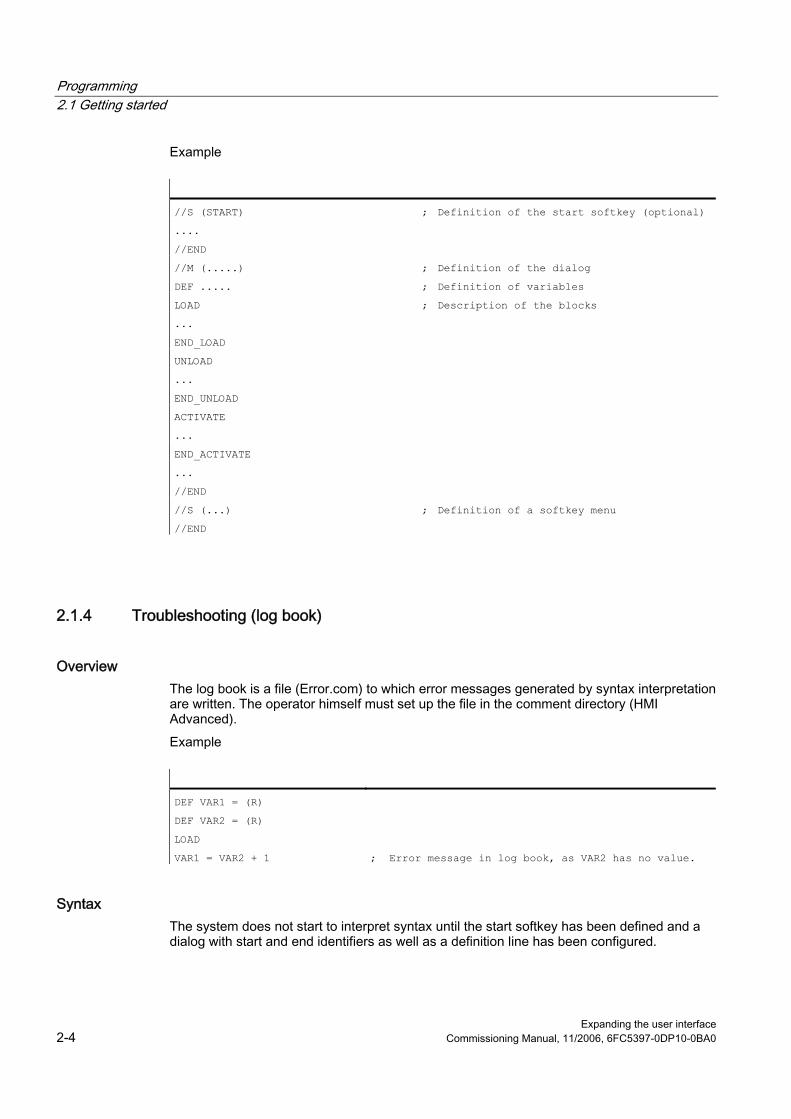
Programming 2.1 Getting started
Expanding the user interface 2-4 Commissioning Manual, 11/2006, 6FC5397-0DP10-0BA0
Example
//S (START) ; Definition of the start softkey (optional)
....
//END
//M (.....) ; Definition of the dialog
DEF ..... ; Definition of variables
LOAD ; Description of the blocks
...
END_LOAD
UNLOAD
...
END_UNLOAD
ACTIVATE
...
END_ACTIVATE
...
//END
//S (...) ; Definition of a softkey menu
//END
2.1.4 Troubleshooting (log book)
Overview The log book is a file (Error.com) to which error messages generated by syntax interpretation are written. The operator himself must set up the file in the comment directory (HMI Advanced). Example
DEF VAR1 = (R)
DEF VAR2 = (R)
LOAD
VAR1 = VAR2 + 1 ; Error message in log book, as VAR2 has no value.
Syntax The system does not start to interpret syntax until the start softkey has been defined and a dialog with start and end identifiers as well as a definition line has been configured.

Programming 2.1 Getting started
Expanding the user interface Commissioning Manual, 11/2006, 6FC5397-0DP10-0BA0 2-5
//S(Start)
HS6=("1st screen form")
PRESS(HS6)
LM("Screen form1")
END_PRESS
//END
//M(Screen form1)�
DEF Var1=(R)
//END
Content of ERROR.COM If "Expand user interface" detects errors when interpreting the configuration files, these errors will be written to the ERROR.COM ASCII file. The file indicates: ● The action during which an error occurred ● The line and column number of the first faulty character ● The entire faulty line of the configuration file If the dialog was created using the PC test environment, then the error file will be stored in the folder referenced by environment variable RAMDISK (HMI Embedded sl). The ERROR.COM file is created only when errors actually occur during interpretation of the configuration files. Storage path of the ERROR.COM file: ● With HMI Embedded sl: In the /tmp/hmiemb folder on the CF card ● With HMI Advanced: In the \DH\COM.DIR\ folder This file is deleted each time HMI Embedded sl / HMI Advanced is restarted.
Displaying the ERROR.COM file HMI Advanced: ● Call the editor in the "Services" or "Startup" operating area. HMI Embedded sl: ● "Setup" operating area → "HMI" → "Editor" → "Temp drive" (4th softkey on vertical softkey
bar; although this softkey is not displayed with the manufacturer password, it will respond). (It is also displayed with the system password.)
● Select ERROR.COM. ● Press the <INPUT> key. ● With the “File functions” softkey, the file can also be copied to a PC by means of a
Windows network drive.

Programming 2.2 Structure and elements of a dialog
Expanding the user interface 2-6 Commissioning Manual, 11/2006, 6FC5397-0DP10-0BA0
2.2 2.2 Structure and elements of a dialog
2.2.1 Defining a dialog
Definition A dialog is part of a user interface consisting of a display line, dialog elements and/or graphics, an output line for messages and 8 horizontal and 8 vertical softkeys. Dialog elements are: ● Variables
– Limits – Default setting of variables
● Help display ● Texts ● Attributes ● System or user variable ● Position of short text ● Position of input/output field ● Colors ● Help (HMI Advanced only) Dialog properties: ● Header ● Graphic ● Dimension ● System or user variable ● Graphic position ● Attributes
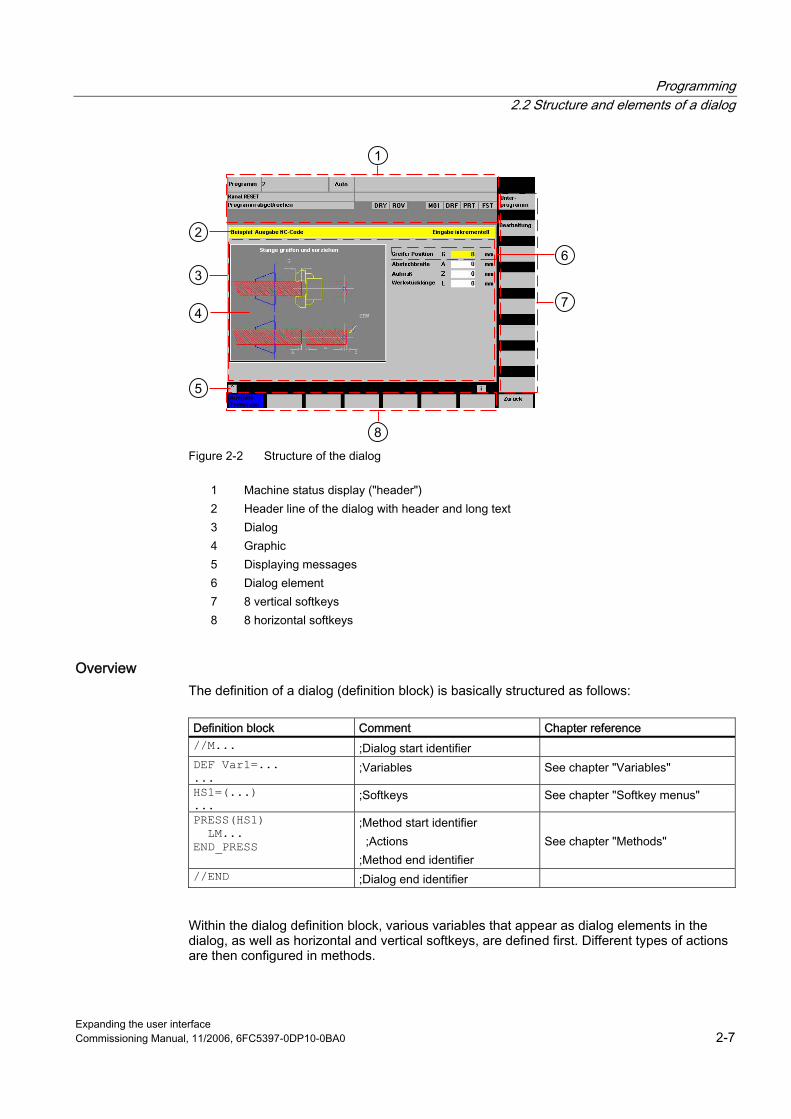
Programming 2.2 Structure and elements of a dialog
Expanding the user interface Commissioning Manual, 11/2006, 6FC5397-0DP10-0BA0 2-7
Figure 2-2 Structure of the dialog
1 Machine status display ("header") 2 Header line of the dialog with header and long text 3 Dialog 4 Graphic 5 Displaying messages 6 Dialog element 7 8 vertical softkeys 8 8 horizontal softkeys
Overview The definition of a dialog (definition block) is basically structured as follows:
Definition block Comment Chapter reference //M... ;Dialog start identifier DEF Var1=... ...
;Variables See chapter "Variables"
HS1=(...) ...
;Softkeys See chapter "Softkey menus"
PRESS(HS1) LM... END_PRESS
;Method start identifier ;Actions ;Method end identifier
See chapter "Methods"
//END ;Dialog end identifier
Within the dialog definition block, various variables that appear as dialog elements in the dialog, as well as horizontal and vertical softkeys, are defined first. Different types of actions are then configured in methods.
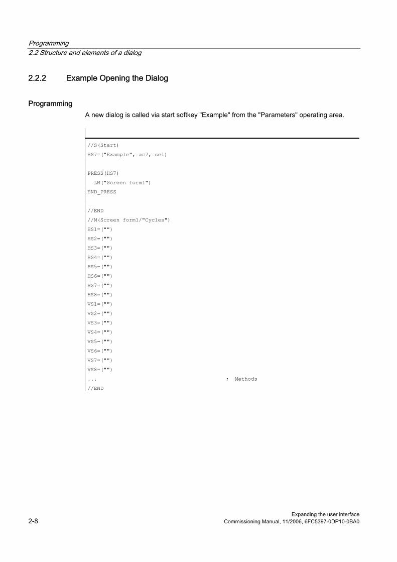
Programming 2.2 Structure and elements of a dialog
Expanding the user interface 2-8 Commissioning Manual, 11/2006, 6FC5397-0DP10-0BA0
2.2.2 Example Opening the Dialog
Programming A new dialog is called via start softkey "Example" from the "Parameters" operating area.
//S(Start)
HS7=("Example", ac7, se1)
PRESS(HS7)
LM("Screen form1")
END_PRESS
//END
//M(Screen form1/"Cycles")
HS1=("")
HS2=("")
HS3=("")
HS4=("")
HS5=("")
HS6=("")
HS7=("")
HS8=("")
VS1=("")
VS2=("")
VS3=("")
VS4=("")
VS5=("")
VS6=("")
VS7=("")
VS8=("")
... ; Methods
//END
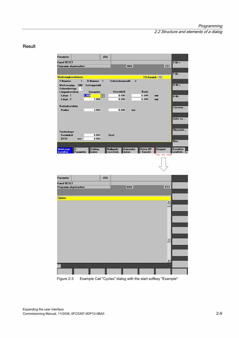
Programming 2.2 Structure and elements of a dialog
Expanding the user interface Commissioning Manual, 11/2006, 6FC5397-0DP10-0BA0 2-9
Result
Figure 2-3 Example Call "Cycles" dialog with the start softkey "Example"
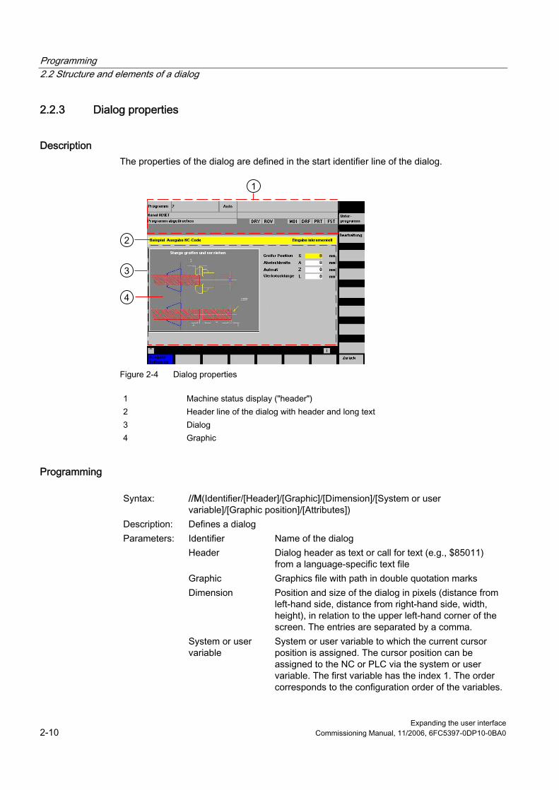
Programming 2.2 Structure and elements of a dialog
Expanding the user interface 2-10 Commissioning Manual, 11/2006, 6FC5397-0DP10-0BA0
2.2.3 Dialog properties
Description The properties of the dialog are defined in the start identifier line of the dialog.
Figure 2-4 Dialog properties
1 Machine status display ("header") 2 Header line of the dialog with header and long text 3 Dialog 4 Graphic
Programming
Syntax: //M(Identifier/[Header]/[Graphic]/[Dimension]/[System or user variable]/[Graphic position]/[Attributes])
Description: Defines a dialog Parameters: Identifier Name of the dialog Header Dialog header as text or call for text (e.g., $85011)
from a language-specific text file Graphic Graphics file with path in double quotation marks Dimension Position and size of the dialog in pixels (distance from
left-hand side, distance from right-hand side, width, height), in relation to the upper left-hand corner of the screen. The entries are separated by a comma.
System or user variable
System or user variable to which the current cursor position is assigned. The cursor position can be assigned to the NC or PLC via the system or user variable. The first variable has the index 1. The order corresponds to the configuration order of the variables.

Programming 2.2 Structure and elements of a dialog
Expanding the user interface Commissioning Manual, 11/2006, 6FC5397-0DP10-0BA0 2-11
Graphic position Position of the graphic in pixels (distance from left-hand side, distance from right-hand side), in relation to the upper left-hand corner of the dialog. The minimum distance from the top is 18 pixels. The entries are separated by a comma.
Attributes The specifications of the attributes are separated by a comma. Possible attributes are:
CMx Column mode: Column alignment CM0 Default: The column distribution is carried out
separately for each line. CM1 The column distribution of the line with the most
columns applies to all lines. CB CHANGE block: Response when dialog is opened: cb
attributes specified for a variable in a variables definition take priority over the default setting in the dialog definition.
CB0 Default: All CHANGE blocks associated with the dialog are processed when it is opened.
CB1 CHANGE blocks are then only processed if the relevant value changes.
System The "System" property can be read during runtime: 0: HMI_Embedded 1: HMI_Advanced
Accessing the dialog properties Read and write access is provided to the following dialog properties within Methods (e.g., PRESS block) ● Hd = Header ● Hlp = Help display ● Var = System or user variable

Programming 2.2 Structure and elements of a dialog
Expanding the user interface 2-12 Commissioning Manual, 11/2006, 6FC5397-0DP10-0BA0
Example
//S(Start)
HS7=("Example", se1, ac7)
PRESS(HS7)
LM("Screen form1")
END_PRESS
//END
//M(Screen form1/"Example 2 : Display graphics"/"MCP.BMP")
HS1=("new%nheader")
HS2=("")
HS3=("")
HS4=("")
HS5=("")
HS6=("")
HS7=("")
HS8=("")
VS1=("")
VS2=("")
VS3=("")
VS4=("")
VS5=("")
VS6=("")
VS7=("")
VS8=("")
PRESS(HS1)
Hd = "new header"
END_PRESS
...
//END
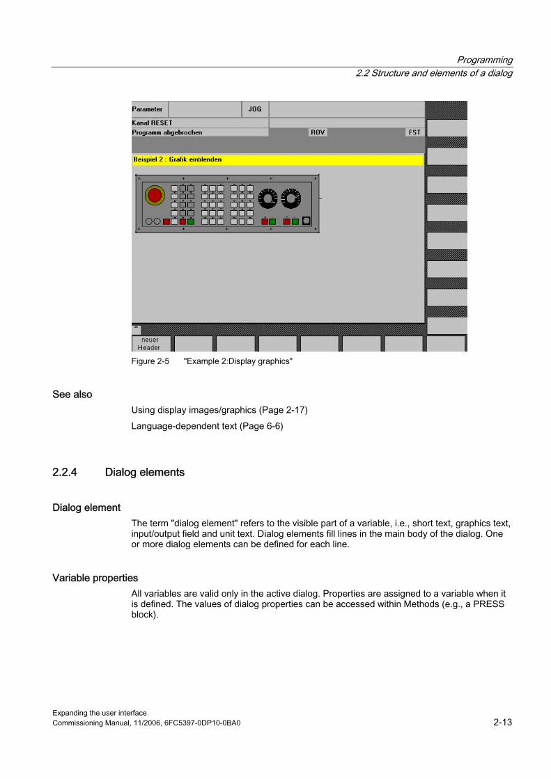
Programming 2.2 Structure and elements of a dialog
Expanding the user interface Commissioning Manual, 11/2006, 6FC5397-0DP10-0BA0 2-13
Figure 2-5 "Example 2:Display graphics"
See also Using display images/graphics (Page 2-17) Language-dependent text (Page 6-6)
2.2.4 Dialog elements
Dialog element The term "dialog element" refers to the visible part of a variable, i.e., short text, graphics text, input/output field and unit text. Dialog elements fill lines in the main body of the dialog. One or more dialog elements can be defined for each line.
Variable properties All variables are valid only in the active dialog. Properties are assigned to a variable when it is defined. The values of dialog properties can be accessed within Methods (e.g., a PRESS block).
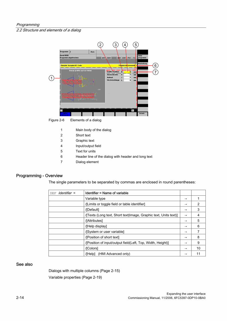
Programming 2.2 Structure and elements of a dialog
Expanding the user interface 2-14 Commissioning Manual, 11/2006, 6FC5397-0DP10-0BA0
Figure 2-6 Elements of a dialog
1 Main body of the dialog 2 Short text 3 Graphic text 4 Input/output field 5 Text for units 6 Header line of the dialog with header and long text 7 Dialog element
Programming - Overview The single parameters to be separated by commas are enclosed in round parentheses:
DEF Identifier = Identifier = Name of variable Variable type → 1 /[Limits or toggle field or table identifier] → 2 /[Default] → 3 /[Texts (Long text, Short text|Image, Graphic text, Units text)] → 4 /[Attributes] → 5 /[Help display] → 6 /[System or user variable] → 7 /[Position of short text] → 8 /[Position of input/output field(Left, Top, Width, Height)] → 9 /[Colors] → 10 /[Help] (HMI Advanced only) → 11
See also Dialogs with multiple columns (Page 2-15) Variable properties (Page 2-19)
Programming 2.2 Structure and elements of a dialog
Expanding the user interface Commissioning Manual, 11/2006, 6FC5397-0DP10-0BA0 2-15
2.2.5 Dialogs with multiple columns
Overview Multiple variables can also be represented in a dialog on one line. In this case, the variables are all defined in the configuration file on a single definition line. DEF VAR11 = (S///"Var11"), VAR12 = (I///"Var12") To make individual variables in the configuration file more legible, the definition lines can be wrapped after every variables definition and following comma. The key word "DEF" always indicates the beginning of a new line: DEF Tnr1=(I//1/"","T ",""/wr1///,,10/20,,50), TOP1=(I///,"Type="/WR2//"$TC_DP1[1,1]"/80,,30/120,,50), TOP2=(R3///,"L1="/WR2//"$TC_DP3[1,1]"/170,,30/210,,70), TOP3=(R3///,"L2="/WR2//"$TC_DP4[1,1]"/280,,30/320,,70), TOP4=(R3///,"L3="/WR2//"$TC_DP5[1,1]"/390,,30/420,,70) DEF Tnr2=(I//2/"","T ",""/wr1///,,10/20,,50), TOP21=(I///,"Typ="/WR2//"$TC_DP1[2,1]"/80,,30/120,,50), TOP22=(R3///,"L1="/WR2//"$TC_DP3[2,1]"/170,,30/210,,70), TOP23=(R3///,"L2="/WR2//"$TC_DP4[2,1]"/280,,30/320,,70), TOP24=(R3///,"L3="/WR2//"$TC_DP5[2,1]"/390,,30/420,,70) ... When creating dialogs with multiple columns, the options of the hardware being used should be taken into consideration, e.g., HMI Embedded sl supports up to 10 columns and 60 DEF instructions.
2.2.6 Unifying the dialog appearance
Boundary condition If HMI Advanced is installed together with ShopMill or ShopTurn on one operator panel, then the two systems have different font types. HMI Advanced has "proportional fonts", while JobShop products and HMI Embedded sl have a "fixed font". If "Expand user interface" is used on HMI Embedded sl and HMI Advanced, dialogs that are defined identically will appear differently by default.

Programming 2.2 Structure and elements of a dialog
Expanding the user interface 2-16 Commissioning Manual, 11/2006, 6FC5397-0DP10-0BA0
Figure 2-7 Appearance in HMI Embedded sl
Below you can see how, despite being configured identically, the same screen appears differently under HMI Advanced.
Figure 2-8 Appearance in HMI Advanced

Programming 2.2 Structure and elements of a dialog
Expanding the user interface Commissioning Manual, 11/2006, 6FC5397-0DP10-0BA0 2-17
Setting for the same screen appearance In order for the appearance in HMI Advanced to tally with that in HMI Embedded sl, the font is changed to a fixed font in the configuration file WIZARD.INI: [FONT] FixedFont=1 The text will be displayed in the current language in fixed font format. The only exception is text for the softkey labels. Unlike the HMI Embedded sl input field, the HMI Advanced input field contains an input mode pictogram. This means it is smaller than the HMI Embedded sl field. As you can see above, the combination of short text, graphic text, input field, and unit text is approximately the same length and contains the same information in both screens. However, individual fields can be positioned differently in the two HMI versions depending on the length of the text to be displayed and the text field within which it will be contained. To enable a common configuration file to be produced for both systems, the SYSTEM dialog property has been created. The runtime environment can be scanned in the SYSTEM dialog property. This enables a common configuration to be used for both target systems.
2.2.7 Using display images/graphics
Use of graphics There are two display categories: ● Display images/graphics in the graphic area ● Help displays illustrating, for example, individual variables, which are superimposed in the
graphic area. ● More Help displays can be configured instead of short text or an input/output field, which
you position where you like.
Maximum size System 560 * 326 pixels HMI Advanced/HMI Embedded sl 688 * 376 pixels PCU 50 with OP 012
Creating screen images for HMI Embedded sl Create the screen images using, e. g., the MS Paint application. HMI Embedded sl can handle converted graphics as well as BMP files. Graphics created using the conversion program BMP2BIN can continue to be used. For BMP files, the colors are converted online. For this purpose, the files containing the color table (syscol.col, sysbw.col, etc.) have been extended to include the [BMP] section. This section allocates a color of a BMP pixel to a color in HMI Embedded.
Programming 2.2 Structure and elements of a dialog
Expanding the user interface 2-18 Commissioning Manual, 11/2006, 6FC5397-0DP10-0BA0
Storage locations HMI Embedded sl automatically finds the resolution of the connected monitor and searches for the desired display image first in the associated resolution directory. If it is not found there, HMI Embedded sl searches for the display image in the next smaller resolution directory until – if it doesn’t find the display image earlier – it reaches directory ico640.
Procedure Procedure when integrating the bitmaps (customer displays): 1. Integration on HMI Embedded sl 2. Generate BMP files using Microsoft Paint, Version 4.0 or higher 3. Use the arj.exe supplied (Version 2.41) to archive the BMP files into archive CUS.ARJ or,
alternatively, archive each BMP file in a separate archive with the file name of the BMP file and extension ".BM_" For example: – Several files per archive:
arj a cus.arj my_file1.bmp my_file2.bmp my_file3.bmp my_file4.bmp – One file per archive:
arj a my_file1.bm_ my_file1.bmp
Limits Archiving is optional. However, it must be noted that the CF card has space for at least 10 MB. A bitmap can be assigned to any softkey if the softkey text is preceded by 2 backslashes. The text behind the backslashes is then interpreted as the name of the file that contains the bitmap. For example, in ALUC.TXT 85000 0 0 "\\mybitmap.bmp"
Note The display colors might not appear in the same format in HMI Embedded sl and in Paint.
Display building, HMI Advanced Graphic programs can be freely selected provided that they are capable of generating the prescribed formats. Graphics, display images and Help displays can have the following format: ● Bitmap (BMP) ● Windows Metafile (WMF) ● Icon (ICO)

Programming 2.3 Variables
Expanding the user interface Commissioning Manual, 11/2006, 6FC5397-0DP10-0BA0 2-19
"Display in display" You can insert further displays in the background (Help display), even as a function of the values of variables.Like for softkeys you can assign a graphics file to a display field. Examples: ● Short text field is overlaid with graphics:
DEF VAR1=(S///,"\\image1.bmp" ////160,40,50,50) ;Type S irrelevant ● Toggle field overlaid with graphics, the graphic being selected with a PLC flag byte:
DEF VAR1=(IDB/*1="\\image1.bmp",2="\\image2.bmp"//,$85000/wr1//"MB[0]"//160,40,50,50)
The height of the displayed graphic (of the I/O field) is specified as the fourth parameter in respect of the positions. You can also define bitmaps in fields (short text, I/O field).
See also Search function for images (Page 6-14) List of colors (Page A-5)
2.3 2.3 Variables
2.3.1 Variable properties
Variable value The most basic property of a variable is its value. The value of variables can be assigned by means of: ● Default settings when defining variables ● Assignment to a system or user variable ● A method
Programming
Syntax: Identifier val = Variable value Identifier = Variable value
Description: Variable value val (value) Parameters: Identifier: Name of the variable Variable value: Value of variable Example VAR3 = VAR4 + SIN(VAR5)
VAR3.VAL = VAR4 + SIN(VAR5)
Programming 2.3 Variables
Expanding the user interface 2-20 Commissioning Manual, 11/2006, 6FC5397-0DP10-0BA0
Variable status The "Variable status" property can be scanned during runtime to find out whether a variable has a valid value. This property can be read and written with the value FALSE = 0.
Programming
Syntax: Identifier.vld Description: Variable status vld (validation) Parameters: Identifier: Name of the variable
FALSE =TRUE =
The result of the scan can be: invalid value valid value
Example IF VAR1.VLD == FALSE VAR1 = 84 ENDIF
Variable: Changing properties When a change is made, a new value is assigned to the variables in the notation Identifier.Property = Value . The expression to the right of the equality sign is evaluated and assigned to the variable or variable property. Examples:
Identifier.ac = Access level (ac: access level) Identifier.al = Text alignment (al: alignment) Identifier.bc = Background color (bc: background color) Identifier.fc = Foreground color (fc: foreground color) Identifier.fs = Font size (fs: font size) Identifier.gt = Graphic text (gt: graphic text) Identifier.hlp = Help display (hlp: help) Identifier.htx = Help text (htx: help text) Identifier.li = Limit (li: limit) Identifier.lt = long text (lt: long text) Identifier.max = MAX limits (max: maximum) Identifier.min = MIN limits (min: minimum) Identifier.st = short text (st: short text) Identifier .typ = Variable type (typ: type) Identifier.ut = Unit text (ut: unit text) Identifier.val = Variable value (val: value) Identifier.var = System or user variable (var: variable) Identifier.vld = Variable status (vld: validation) Identifier .wr = Input mode (wr: write)

Programming 2.3 Variables
Expanding the user interface Commissioning Manual, 11/2006, 6FC5397-0DP10-0BA0 2-21
2.3.2 Programming variables
Programming The parameters of the variables are explained briefly in the following overview. A comprehensive description can be found in subsequent chapters.
Parameter Description 1 Variable type The variable type must be specified. R[x]:
I: S[x]:
C: B: V:
REAL (+ digit for the decimal place) INTEGER STRING (+ digit for string length) CHARACTER (individual character) BOOL VARIANT
2 Limits Limit value MIN, limit value MAX Default: Empty The limit values are separated by a comma. Limits can be specified for types I, C and R in decimal formats or as characters in the form "A", "F".
Toggle field List with predefined entries in the I/O field: The list starts with a * and the entries are separated by commas. The entries can be assigned a value. For the toggle field, the entry for the limit is interpreted as a list. If only one * is entered, a variable toggle field is created. Default: none
Table identifiers Identifiers of a table containing NCK/PLC values of the same type, which can be addressed via a channel block. The table identifier is differentiated from limits or toggle fields by the addition of a % sign in front of it.The file containing the table description can be specified by adding a comma after the identifier and then inserting the name of the file.
3 Default setting If a default setting has not been configured and no system or user variable has been assigned to the variable, the first element of the toggle field is assigned. If no toggle field has been defined, there is no default setting, i.e., the status of the variable is "not calculated". Default: No default The sequence is specified. Instead of a short text, an image can also be displayed. Default: Empty
4 Texts
Long text: Short text: Graphic text: Unit text:
Text in the display line Name of the dialog element Text refers to the terms in the graphics Unit of the dialog element
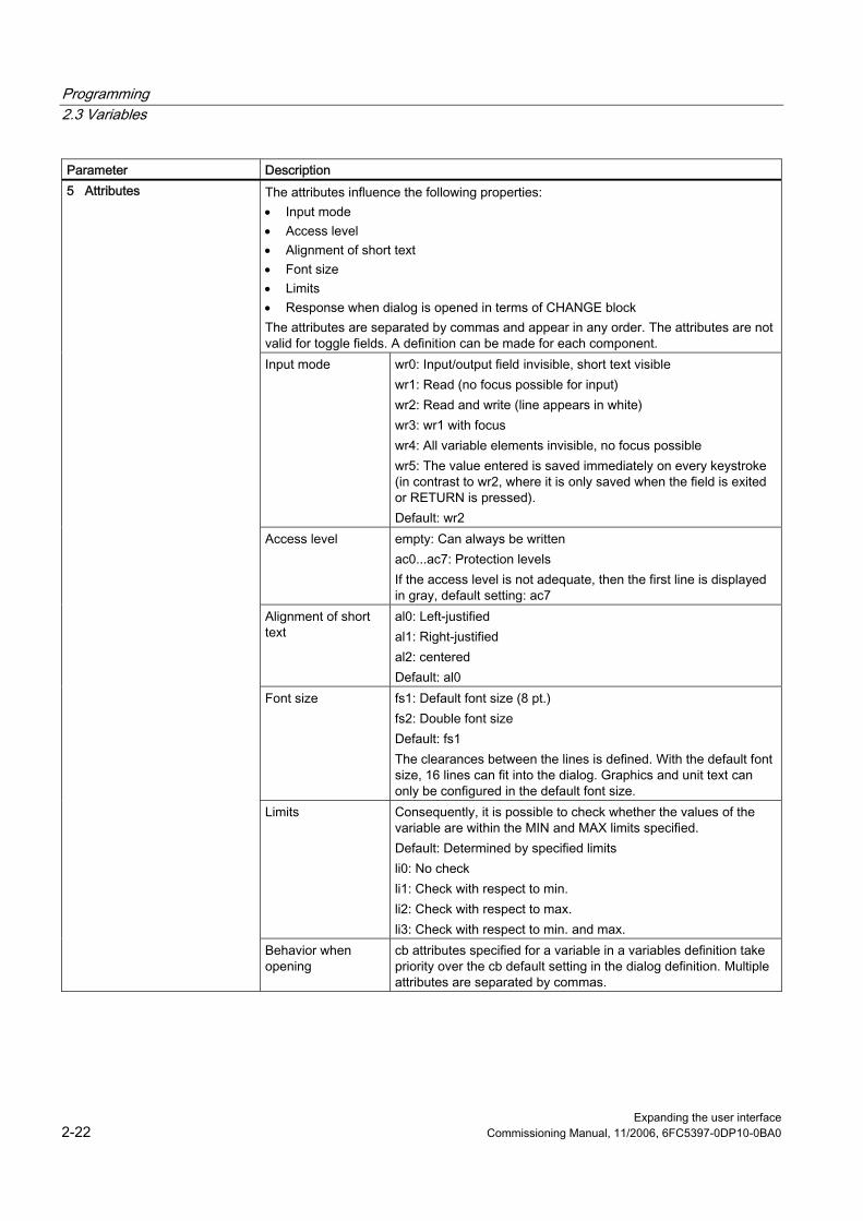
Programming 2.3 Variables
Expanding the user interface 2-22 Commissioning Manual, 11/2006, 6FC5397-0DP10-0BA0
Parameter Description The attributes influence the following properties: • Input mode • Access level • Alignment of short text • Font size • Limits • Response when dialog is opened in terms of CHANGE block The attributes are separated by commas and appear in any order. The attributes are not valid for toggle fields. A definition can be made for each component. Input mode wr0: Input/output field invisible, short text visible
wr1: Read (no focus possible for input) wr2: Read and write (line appears in white) wr3: wr1 with focus wr4: All variable elements invisible, no focus possible wr5: The value entered is saved immediately on every keystroke (in contrast to wr2, where it is only saved when the field is exited or RETURN is pressed). Default: wr2
Access level empty: Can always be written ac0...ac7: Protection levels If the access level is not adequate, then the first line is displayed in gray, default setting: ac7
Alignment of short text
al0: Left-justified al1: Right-justified al2: centered Default: al0
Font size fs1: Default font size (8 pt.) fs2: Double font size Default: fs1 The clearances between the lines is defined. With the default font size, 16 lines can fit into the dialog. Graphics and unit text can only be configured in the default font size.
Limits Consequently, it is possible to check whether the values of the variable are within the MIN and MAX limits specified. Default: Determined by specified limits li0: No check li1: Check with respect to min. li2: Check with respect to max. li3: Check with respect to min. and max.
5 Attributes
Behavior when opening
cb attributes specified for a variable in a variables definition take priority over the cb default setting in the dialog definition. Multiple attributes are separated by commas.
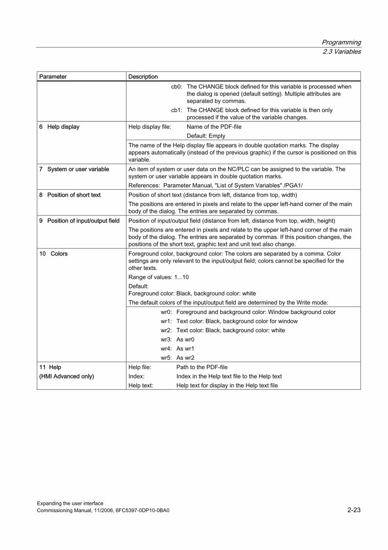
Programming 2.3 Variables
Expanding the user interface Commissioning Manual, 11/2006, 6FC5397-0DP10-0BA0 2-23
Parameter Description cb0:
cb1:
The CHANGE block defined for this variable is processed when the dialog is opened (default setting). Multiple attributes are separated by commas. The CHANGE block defined for this variable is then only processed if the value of the variable changes.
Help display file: Name of the PDF-file Default: Empty
6 Help display
The name of the Help display file appears in double quotation marks. The display appears automatically (instead of the previous graphic) if the cursor is positioned on this variable.
7 System or user variable An item of system or user data on the NC/PLC can be assigned to the variable. The system or user variable appears in double quotation marks. References: Parameter Manual, "List of System Variables" /PGA1/
8 Position of short text Position of short text (distance from left, distance from top, width) The positions are entered in pixels and relate to the upper left-hand corner of the main body of the dialog. The entries are separated by commas.
9 Position of input/output field Position of input/output field (distance from left, distance from top, width, height) The positions are entered in pixels and relate to the upper left-hand corner of the main body of the dialog. The entries are separated by commas. If this position changes, the positions of the short text, graphic text and unit text also change. Foreground color, background color: The colors are separated by a comma. Color settings are only relevant to the input/output field; colors cannot be specified for the other texts. Range of values: 1...10 Default: Foreground color: Black, background color: white The default colors of the input/output field are determined by the Write mode:
10 Colors
wr0:wr1:wr2:wr3:wr4:wr5:
Foreground and background color: Window background color Text color: Black, background color for window Text color: Black, background color: white As wr0 As wr1 As wr2
11 Help (HMI Advanced only)
Help file: Index: Help text:
Path to the PDF-file Index in the Help text file to the Help text Help text for display in the Help text file
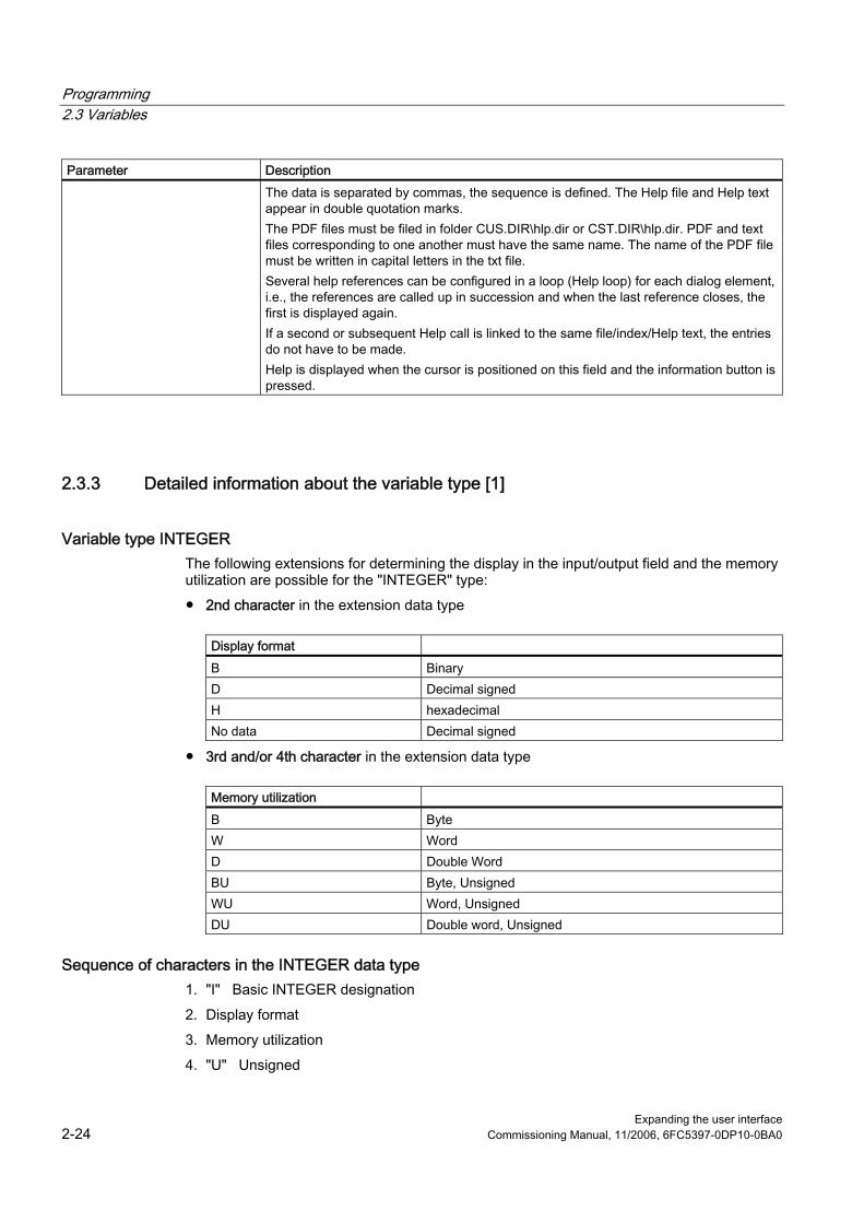
Programming 2.3 Variables
Expanding the user interface 2-24 Commissioning Manual, 11/2006, 6FC5397-0DP10-0BA0
Parameter Description The data is separated by commas, the sequence is defined. The Help file and Help text appear in double quotation marks. The PDF files must be filed in folder CUS.DIR\hlp.dir or CST.DIR\hlp.dir. PDF and text files corresponding to one another must have the same name. The name of the PDF file must be written in capital letters in the txt file. Several help references can be configured in a loop (Help loop) for each dialog element, i.e., the references are called up in succession and when the last reference closes, the first is displayed again. If a second or subsequent Help call is linked to the same file/index/Help text, the entries do not have to be made. Help is displayed when the cursor is positioned on this field and the information button is pressed.
2.3.3 Detailed information about the variable type [1]
Variable type INTEGER The following extensions for determining the display in the input/output field and the memory utilization are possible for the "INTEGER" type: ● 2nd character in the extension data type
Display format B Binary D Decimal signed H hexadecimal No data Decimal signed
● 3rd and/or 4th character in the extension data type
Memory utilization B Byte W Word D Double Word BU Byte, Unsigned WU Word, Unsigned DU Double word, Unsigned
Sequence of characters in the INTEGER data type 1. "I" Basic INTEGER designation 2. Display format 3. Memory utilization 4. "U" Unsigned

Programming 2.3 Variables
Expanding the user interface Commissioning Manual, 11/2006, 6FC5397-0DP10-0BA0 2-25
Valid INTEGER type specifications: IB Integer variable 32 bits in binary notation IBD Integer variable 32 bits in binary notation IBW Integer variable 16 bits in binary notation IBB Integer variable 8 bits in binary notation I Integer variable 32 bits in decimal notation signed IDD Integer variable 32 bits in decimal notation signed IDW Integer variable 16 bits in decimal notation signed IDB Integer variable 8 bits in decimal notation signed IDDU Integer variable 32 bits in decimal notation unsigned IDWU Integer variable 16 bits in decimal notation unsigned IDBU Integer variable 8 bits in decimal notation unsigned IH Integer variable 32 bits in hexadecimal notation IHDU Integer variable 32 bits in hexadecimal notation IHWU Integer variable 16 bits in hexadecimal notation IHBU Integer variable 8 bits in hexadecimal notation
VARIANT variable type The VARIANT variable type is determined by the data type of the last value assignment. It can be scanned using the ISNUM or ISSTR functions. The VARIANT type is mainly suited to write either variable names or numerical values to the NC code.
Programming The data type of variables can be checked:
Syntax: ISNUM (VAR) Parameters: VAR Name of the variable whose data type is to be checked.
FALSE = TRUE =
The result of the scan can be: not a numerical variable (data type = STRING) numerical variable (data type = REAL)
Syntax: ISSTR (VAR) Parameters: VAR Name of the variable whose data type is to be checked.
FALSE = TRUE =
The result of the scan can be: numerical variable (data type = REAL) not a numerical variable (data type = STRING)
Example IF ISNUM(VAR1) == TRUE IF ISSTR(REG[4]+2) == TRUE

Programming 2.3 Variables
Expanding the user interface 2-26 Commissioning Manual, 11/2006, 6FC5397-0DP10-0BA0
The display mode of variables can be changed: ● For INTEGER, the display type can be changed.
B Binary D Decimal signed H hexadecimal unsigned With the addition of U for Unsigned
● For REAL data types, only the number of places after the decimal point can be changed. Changing the type is illegal and generates an error message in the ERROR.COM file. Example Var1.typ = "IBW" Var2.typ = "R3"
Number representation Numbers can be represented in either binary, decimal, hexadecimal or exponential notation. Numerical values in binary, hexadecimal and exponential notation must be enclosed in single quotation marks:
Binary 'B01110110' decimal 123.45 hexadecimal 'HF1A9' exponential '-1.23EX-3' Examples: VAR1 = 'HF1A9'
REG[0]= 'B01110110'
DEF VAR7 = (R//'-1.23EX-3')
Note When codes are generated with the "GC" function, only numerical values in decimal or exponential notation are evaluated, but not those in binary or hexadecimal notation.

Programming 2.3 Variables
Expanding the user interface Commissioning Manual, 11/2006, 6FC5397-0DP10-0BA0 2-27
2.3.4 Detailed information about the toggle field [2]
Description The toggle field extension function can be used to display texts (entries in toggle field) as a function of NC/PLC variables. A variable, which makes use of a toggle field extension, is read-only.
Programming
Syntax: DEF Identifier =(Variable type /+ $Text number | * value="\\display"[,value="\\image2.bmp"][, ...] /[Default] /[Texts(Long text, Short text, Graphic text, Units text)] /[Attributes] /[Help display] /[System or user variable] /[Position of short text] /[Position input/output field(Left, Top, Width, Height)] /[Colors] /[Help])
Description: When the dialog is opened, the content of text number $85015 is displayed in the input/output field. Default value 15 is entered in system variable DB90.DBB5. If the value saved in system variable DB90.DBB5 changes, then the displayed text number $(85000 + <DB90.DBB5>) is recalculated in response to every change.
Parameters: Variable type Type of variables specified in the system or user variable
Text number Number (basis) of the language-specific text valid as the basis number.
System or user variable
System or user variable (offset) via which the final text number (basis + offset) is displayed.
Example DEF VAR1=(IB/+ $85000/15////"DB90.DBB5")
Variable toggle field It is possible to assign a variable toggle field to a dialog element, i.e., when the toggle key is pressed, a value configured in a CHANGE method is assigned to the variable. An asterisk * is entered in the Limits or Toggle Field property to identify a variable toggle field when a variable is defined. Example: DEF VAR1=(S/*)
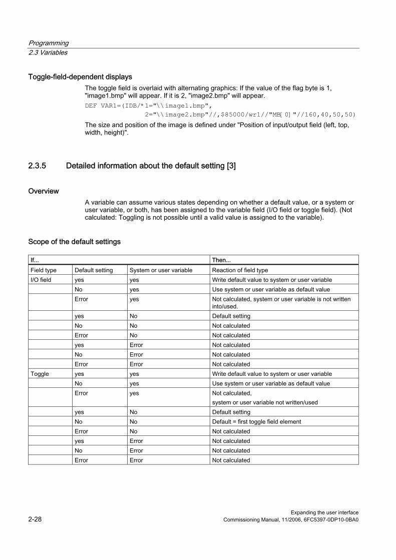
Programming 2.3 Variables
Expanding the user interface 2-28 Commissioning Manual, 11/2006, 6FC5397-0DP10-0BA0
Toggle-field-dependent displays The toggle field is overlaid with alternating graphics: If the value of the flag byte is 1, "image1.bmp" will appear. If it is 2, "image2.bmp" will appear. DEF VAR1=(IDB/*1="\\image1.bmp", 2="\\image2.bmp"//,$85000/wr1//"MB[0]"//160,40,50,50) The size and position of the image is defined under "Position of input/output field (left, top, width, height)".
2.3.5 Detailed information about the default setting [3]
Overview A variable can assume various states depending on whether a default value, or a system or user variable, or both, has been assigned to the variable field (I/O field or toggle field). (Not calculated: Toggling is not possible until a valid value is assigned to the variable).
Scope of the default settings If... Then... Field type Default setting System or user variable Reaction of field type I/O field yes yes Write default value to system or user variable No yes Use system or user variable as default value Error yes Not calculated, system or user variable is not written
into/used. yes No Default setting No No Not calculated Error No Not calculated yes Error Not calculated No Error Not calculated Error Error Not calculated Toggle yes yes Write default value to system or user variable No yes Use system or user variable as default value Error yes Not calculated,
system or user variable not written/used yes No Default setting No No Default = first toggle field element Error No Not calculated yes Error Not calculated No Error Not calculated Error Error Not calculated
Programming 2.3 Variables
Expanding the user interface Commissioning Manual, 11/2006, 6FC5397-0DP10-0BA0 2-29
2.3.6 Detailed information about the position of the short text [8] and position of the input/output field [9]
Overview The short text and graphic text, as well as the input/output field and unit text, are each treated like a unit, i.e., position settings for short text apply to the graphic text and settings for the input/output field and to unit text.
Programming The configured position entry overwrites the default value, i.e., only one value can be changed. If no position settings have been configured for subsequent screen form elements, then the position settings for the preceding screen form element are applied. If no positions have been specified for any dialog elements, the default setting is applied. By default, the column width for the short text and input/output field is calculated for each line based on the number of columns and maximum line width, i.e.,column width = maximum line width/number of columns. The width of the graphics and unit text is predefined and optimized to suit the requirements of programming support. If graphics or unit text has been configured, the width of the short text or I/O field is reduced accordingly. The order of short text and I/O field can be reversed by position settings.
2.3.7 Detailed information about on Help [11] (HMI-Advanced only)
Description The Help loop for a dialog element can be extended or deleted during runtime. The Help loop can be extended as required by calling the function repeatedly.
Programming
Syntax: ADDHTX (Identifier, Help file, Index, Help text) Description: Extends the Help loop Parameters: Identifier Name of the variable whose Help loop is to be
expanded. Help file:
Index: Help text:
Path specification of the file (PDF format) Index in the Help text file to the Help text Help text for display in the Help text file
Example ADDHTX(VAR1,"C:\OEM\HLP\MYHLP.PDF",15,"Machine data")
Programming 2.3 Variables
Expanding the user interface 2-30 Commissioning Manual, 11/2006, 6FC5397-0DP10-0BA0
Syntax: CLRHTX (Identifier) Description: Deletes the Help loop Parameters: Identifier Name of the variable whose Help loop is to be deleted Help file:
Index: Help text:
Path specification of the file (PDF format) Index in the Help text file to the Help text Help text for display in the Help text file
Example CLRHTX(VAR1)
2.3.8 Application examples
Help variables Help variables are internal arithmetic variables. Arithmetic variables are defined like other variables, but have no other properties apart from variable value and status, i.e., Help variables are not visible in the dialog. Help variables are of the VARIANT type.
Programming
Syntax: DEF Identifier Description: Internal arithmetic variables of the VARIANT type Parameters: Identifier: Name of Help variables Example DEF OTTO ;Definition of a Help variable
Syntax: Identifier.val = Help variable value
Identifier = Help variable value Description: A value is assigned to a Help variable in a method. Parameters: Identifier: Name of Help variables Help variable value: Content of the Help variables
Example
LOAD
OTTO = "Test"
END_LOAD
;
Assign the value "Test" to the Otto Help variable
LOAD
OTTO = REG[9].VAL
END_LOAD
;
Assign value of register to the Help variable

Programming 2.3 Variables
Expanding the user interface Commissioning Manual, 11/2006, 6FC5397-0DP10-0BA0 2-31
Calculation with variables Variables are calculated every time you exit an input/output field (by pressing the ENTER or TOGGLE key). The calculation is configured in a CHANGE method that is processed every time the value changes. You can scan the variable status to ascertain the validity of the value of the variable, e.g., Var1 = Var5 + SIN(Var2) Otto = PI * Var4
Addressing system variables indirectly A system variable can also be addressed indirectly, i.e., as a function of another variable: PRESS(HS1) AXIS=AXIS+1 WEG.VAR="$AA_DTBW["<<AXIS<<"]" ;Address axis address via variable END_PRESS
Changing the softkey label Example HS3.st = "New Text" ;Change softkey label
2.3.9 Example 1: Assigning the Variable Type, Texts, Help, Colors properties
Example 1 Assigning the Variable Type, Texts, Help, Colors properties
DEF Var1 = (R///,"Actual value",,"mm"//"Var1.bmp"////8,2) Variable Type: REAL Limits or toggle field entries: none Default: none Texts: Long text: None Short text: Actual value Graphic text: none Unit text: mm Attributes: none Help display: Var1.bmp System or user variable: none Position of short text: No data, i.e., default position Position of input/output field:
No data, i.e., default position
Programming 2.3 Variables
Expanding the user interface 2-32 Commissioning Manual, 11/2006, 6FC5397-0DP10-0BA0
DEF Var1 = (R///,"Actual value",,"mm"//"Var1.bmp"////8,2) Colors: Foreground color: 8 Background color: 2 Help: none
2.3.10 Example 2: Assigning the Variable Type, Limits, Attributes, Short Text Position properties
Example 2 Assigning the Variable Type, Limits, Attributes, Short Text Position properties
DEF Var2 = (I/0,10///wr1,al1///,,300) Variable Type: INTEGER Limits or toggle field entries: MIN: 0
MAX: 10
Default: none Texts: none Attributes: Input mode read-only Alignment of short text Right-justified Help display: none System or user variable: none Position of short text: Distance from left None Distance from top None, i.e., default distance from top left Width: 300 Position of input/output field: No data, i.e., default position Colors: No data, i.e., default Help: none

Programming 2.3 Variables
Expanding the user interface Commissioning Manual, 11/2006, 6FC5397-0DP10-0BA0 2-33
2.3.11 Example 3: Assigning the Variable Type, Default, System or User Variable, Input/Output Field Position properties
Example 3 Assigning the Variable Type, Default, System or User Variable, Input/Output Field Position properties
DEF Var3 =(R//10////"$R[1]"//300,10,200//"Help.pdf",1,"Help1") Variable Type: String Limits or toggle field entries: none Default: 10 Texts: none Attributes: none Help display: none System or user variable: $R[1] (R-Parameter 1) Position of short text: Default position in relation to input/output
field Position of input/output field: Distance from left 300 Distance from top 10 Width: 200 Colors: No data, i.e., default Help: In file Help.pdf, Help with the Help text
"Help1" is called on the page with the index 1 when the <i> button is pressed.
2.3.12 Examples relating to toggle field, Help call and image display
Example 4 Various entries in the toggle field:
Limits or toggle field entries: DEF Var1 = (I/* 0,1,2,3)
DEF Var2 = (S/* "In", "Out") DEF Var3 = (B/* 1="In", 0="Out")DEF Var4 = (R/* ARR1)
;1 and 0 are values, "In" and "Out" are displayed. ;ARR1 is the name of an array.

Programming 2.3 Variables
Expanding the user interface 2-34 Commissioning Manual, 11/2006, 6FC5397-0DP10-0BA0
Example 5 (HMI Advanced only) Several Help calls per dialog element:
DEF Var5 = (R//////////"Help1.pdf",1,"Help1",,2,"Help2","Help3.pdf",3,) Variable Type: REAL Limits or toggle field entries: none Default: none Texts: none Attributes: none Help display: none System or user variable: none Position of short text: None Position of input/output field: none Colors: No data, i.e., default Help: 1. Entry in the Help
loop Help file: Index: Help text: 2. Entry in the Help loop Help file: Index: Help text: 3. Entry in the Help loop Help file: Index: Help text:
HELP1.PDF 1 Help1 HELP2.PDF 2 Help2 HELP3.PDF 3 Help3
Example 6 Displaying an image instead of a short text: the size and position of the image is defined under "Position of input/output field (Left, Top, Width, Height)".
DEF VAR6= (V///,"\\image1.bmp" ////160,40,50,50) Variable Type: VARIANT Limits or toggle field entries: none Default: none Texts: None Attributes: none Help display: none System or user variable: none

Programming 2.3 Variables
Expanding the user interface Commissioning Manual, 11/2006, 6FC5397-0DP10-0BA0 2-35
DEF VAR6= (V///,"\\image1.bmp" ////160,40,50,50) Position of short text: image1.bmp Position of input/output field Distance from left: 160 Distance from the top: 40 Width: 50 Height: 50 Colors: No data, i.e., default Help: none
2.3.13 Use of strings
Strings Strings can be used as part of the configuration. These allow text to be displayed dynamically or different texts to be chained for the purpose of code generation.
Rules The following rules must be observed with regard to string variables: ● Logic operations are processed from left to right. ● Nested expressions are solved from the inside outwards. ● No distinction is made between uppercase and lowercase type. Strings can be deleted simply by assigning a blank string. Strings can be appended after the equality sign using the operator "<<". Quotation marks (") in the string are represented by two successive quotation mark symbols. Strings can be checked for equality in IF instructions.
Example Default settings for the following examples: VAR1.VAL = "This is an" VAR8.VAL = 4 VAR14.VAL = 15 VAR2.VAL = "Error" $85001 = "This is an" $85002 = "Alarm text"

Programming 2.3 Variables
Expanding the user interface 2-36 Commissioning Manual, 11/2006, 6FC5397-0DP10-0BA0
Editing strings: ● Chaining of strings:
VAR12.VAL = VAR1 << " Error." ;Result: "This is an error" ● Deleting a variable:
VAR10.VAL = "" ;Result: Blank string ● Setting a variable with a text variable:
VAR11.VAL = VAR1.VAL ;Result: "This is an" ● Data type matching:
VAR13.VAL ="This is the " << (VAR14 - VAR8) << "th error" ;Result: "This is the 11th error"
● Treatment of numerical values: VAR13.VAL = "Error " << VAR14.VAL << ": " << $T80001 << $T80002 ;Result: "Error 15: This is an alarm text" IF VAR15 == "Error" ;Strings in IF statement VAR16 = 18.1234 ;Result: VAR16 equals 18.1234, ;if VAR15 equals "Error". ENDIF
● Quotation marks within a string: VAR2="Hello, this is a "" Test" ;Result: Hello, this is a " Test
● System or user-variable strings dependent on variable content: VAR2.Var = "$R[" << VAR8 << "]" ;Result: $R[4]
2.3.14 CURPOS variable
Description Using the CURPOS variable, it is possible to display or manipulate the position of the cursor in the active input field of the current dialog. The variable indicates how many characters are located in front of the cursor. If the cursor is located at the start of the input field, then CURPOS assumes the value of 0. If the value of CURPOS is changed, then the cursor is positioned at the appropriate location in the input field. In order to be able to respond to changes in the variable value, it is possible to monitor for changes using a CHANGE block. If the value of CURPOS changes, then a jump is made to the CHANGE block and the instructions contained there are executed.

Programming 2.3 Variables
Expanding the user interface Commissioning Manual, 11/2006, 6FC5397-0DP10-0BA0 2-37
2.3.15 CURVER variable
Description The CURVER (CURrent VERsion) property allows the programming to be adapted in order to handle different versions. The CURVER variable is read-only.
Note Even if previously recompiled with an older version, the code is automatically generated with the most recent version. The "GC" command always generates the most recent version. An additional identifier indicating the generated version is inserted in the user comment of the generated code in versions > 0.
Rules The most recent dialog with all its variables is always displayed. ● Variables used previously may not be changed. ● New variables are inserted in the existing (cycle) programming in arbitrary order. ● It is not permissible to delete variables from a dialog from one version to the next. ● The dialog must contain all variables of all versions.
Example
(IF CURVER==1 ...) ; When the code is recompiled, CURVER is automatically assigned the version of the recompiled code.

Programming 2.3 Variables
Expanding the user interface 2-38 Commissioning Manual, 11/2006, 6FC5397-0DP10-0BA0
2.3.16 ENTRY variable
Description The ENTRY variable can be used to check by what method a dialog has been called.
Programming
Syntax: ENTRY Description: The ENTRY variable is a read only variable. Return Value: The result of the scan can be: 0 = No programming support 1 = Programming support (the dialog was called by programming
support) 2 = Programming support + default setting from the previous
dialog (sub-dialog) 3 = Programming support + recompilation 4 = Programming support + recompilation with generated
comments, with # sign 5 = Programming support + recompilation with generated
comments, without # sign
Example
IF ENTRY == 0
DLGL("The dialog was not called during programming")
ELSE
DLGL("The dialog was called during programming")
ENDIF
Programming 2.3 Variables
Expanding the user interface Commissioning Manual, 11/2006, 6FC5397-0DP10-0BA0 2-39
2.3.17 ERR variable
Description Variable ERR can be used to check whether the preceding lines have been executed correctly.
Programming
Syntax: ERR Description: The ERR variable is read-only. Return Value: The result of the scan can be: FALSE = previous line was executed error-free TRUE = previous line was not executed error-free
Example
VAR4 = Thread[VAR1,"CDM",3] ; Output value from array
IF ERR == TRUE ; Scan to check whether value has been found in array
VAR5 = "Error accessing array"
; If the value has not been found in the array, the value "Error accessing array" is assigned to the variables.
ELSE
VAR5 = "All OK" ; ;If the value has been found in the array, the value "All OK" is assigned to the variables.
ENDIF

Programming 2.3 Variables
Expanding the user interface 2-40 Commissioning Manual, 11/2006, 6FC5397-0DP10-0BA0
2.3.18 FILE_ERR variable
Description Variable FILE_ERR can be used to check whether the preceding GC or CP command has been executed correctly.
Programming
Syntax: FILE_ERR Description: The FILE_ERR variable is read-only. Return Value: Possible results are: 0 = Operation okay 1 = Drive/path not available 2 = Path/file access error 3 = Drive not ready 4 = Incorrect file name 5 = File is already open 6 = Access denied 7 = Target path not available or not permitted 8 = Copy source same as target 10 = Internal error: FILE_ERR = 10 means that the error cannot be
classified in the other categories.
Example
CP("D:\source.mpf","E:\target.mpf")
; Copy from source.mpf to E:\target.mpf
IF FILE_ERR > 0 ; Scan to ascertain whether error has occurred
IF FILE_ERR == 1 ; Scan specific error numbers and output associated error text
VAR5 = "Drive/path not available"
ELSE
IF FILE_ERR == 2
VAR5 = "Path/file access error"
ELSE
IF FILE_ERR == 3
VAR5 = "Wrong file name"
ENDIF
ENDIF
ENDIF
ELSE

Programming 2.3 Variables
Expanding the user interface Commissioning Manual, 11/2006, 6FC5397-0DP10-0BA0 2-41
CP("D:\source.mpf","E:\target.mpf")
VAR5 = "All OK" ; If no errors have occurred in CP (or GC), "All OK" is output
ENDIF
2.3.19 FOC variable
Description The FOC variable can be used to control the input focus (the current active input/output field) in a dialog. Responses to cursor left, right, up and down movements, as well as PGUP, PGDN, are predefined and cannot be modified.
Note The FOC function may not be initiated as a result of a navigation event. The cursor position may only be changed in softkey PRESS blocks, CHANGE blocks, etc. The FOC function cannot be applied to variables with input mode wr = 0 and wr = 4 or to Help variables.
Programming
Syntax: FOC Description: The variable can be read and written. Return Value: Read The result is the name of the variable to which the
FOC function has been applied. Write It is possible to assign either a string or a numerical
value.A string is interpreted as a variable name and a numerical value as a variable index.
Example
IF FOC == "Var1" ; Read focus
REG[1] = Var1
ELSE
REG[1] = Var2
ENDIF
FOC = "Var1" ; The input focus will be assigned to Variable 1.
FOC = 3 ; The input focus will be assigned to the 3rd dialog element with WR ≥ 2.
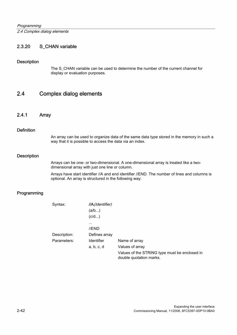
Programming 2.4 Complex dialog elements
Expanding the user interface 2-42 Commissioning Manual, 11/2006, 6FC5397-0DP10-0BA0
2.3.20 S_CHAN variable
Description The S_CHAN variable can be used to determine the number of the current channel for display or evaluation purposes.
2.4 2.4 Complex dialog elements
2.4.1 Array
Definition An array can be used to organize data of the same data type stored in the memory in such a way that it is possible to access the data via an index.
Description Arrays can be one- or two-dimensional. A one-dimensional array is treated like a two-dimensional array with just one line or column. Arrays have start identifier //A and end identifier //END. The number of lines and columns is optional. An array is structured in the following way:
Programming
Syntax: //A(Identifier) (a/b...) (c/d...) ... //END
Description: Defines array Parameters: Identifier Name of array a, b, c, d Values of array
Values of the STRING type must be enclosed in double quotation marks.

Programming 2.4 Complex dialog elements
Expanding the user interface Commissioning Manual, 11/2006, 6FC5397-0DP10-0BA0 2-43
Example
//A(Thread) ; Size/lead/core diameter
(0.3 / 0.075 / 0.202)
(0.4 / 0.1 / 0.270)
(0.5 / 0.125 / 0.338)
(0.6 / 0.15 / 0.406)
(0.8 / 0.2 / 0.540)
(1.0 / 0.25 / 0.676)
(1.2 / 0.25 / 0.676)
(1.4 / 0.3 / 1.010)
(1.7 / 0.35 / 1.246)
//END
2.4.2 Accessing the value of an array element
Description The value of an array access operation can be transferred with property Value (identifier.val). The line index (line number of the array) and the column index (column number of the array) each begin at 0. If a line index or column index is outside the array, the value 0 or a blank string is output and the ERR variable is set to TRUE. The ERR variable is also set to TRUE if a search concept cannot be found.
Programming
Syntax: Identifier [Z,[M[,C]]].val or Identifier [Z,[M[,C]]]
Description: Access to one-dimensional array with only one column Syntax: Identifier [S,[M[,C]]].val] or
Identifier [S,[M[,C]]] or Description: Access to one-dimensional array with only one line Syntax: Identifier [Z,S,[M[,C]]].val or
Identifier [Z,S,[M[,C]]] Description: Access to two-dimensional array Parameters: Identifier: Name of array Z: Line value (line index or search concept)� S: Column value (column index or search concept)�
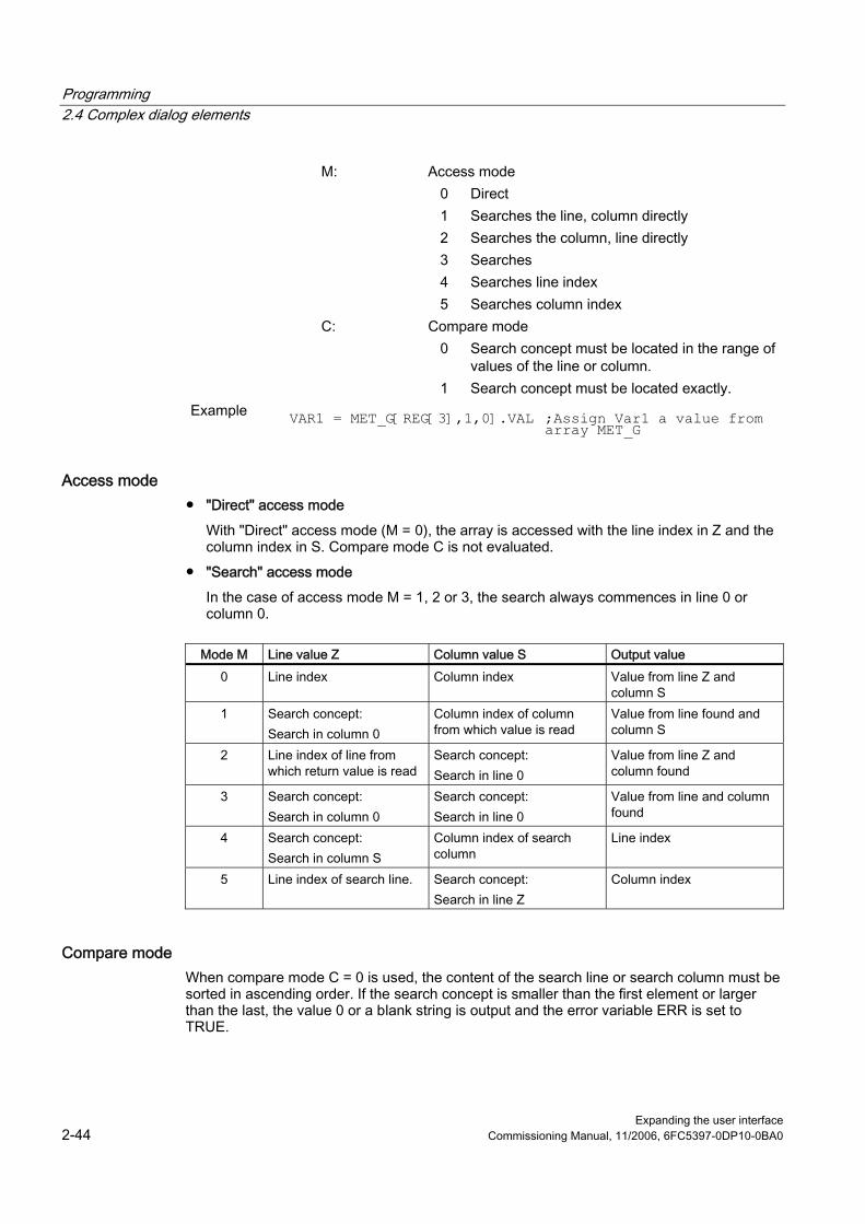
Programming 2.4 Complex dialog elements
Expanding the user interface 2-44 Commissioning Manual, 11/2006, 6FC5397-0DP10-0BA0
M: Access mode 0 Direct 1 Searches the line, column directly 2 Searches the column, line directly 3 Searches 4 Searches line index 5 Searches column index C: Compare mode 0 Search concept must be located in the range of
values of the line or column. 1 Search concept must be located exactly. Example
VAR1 = MET_G[REG[3],1,0].VAL ;Assign Var1 a value from array MET_G
Access mode ● "Direct" access mode
With "Direct" access mode (M = 0), the array is accessed with the line index in Z and the column index in S. Compare mode C is not evaluated.
● "Search" access mode In the case of access mode M = 1, 2 or 3, the search always commences in line 0 or column 0.
Mode M Line value Z Column value S Output value
0 Line index Column index Value from line Z and column S
1 Search concept: Search in column 0
Column index of column from which value is read
Value from line found and column S
2 Line index of line from which return value is read
Search concept: Search in line 0
Value from line Z and column found
3 Search concept: Search in column 0
Search concept: Search in line 0
Value from line and column found
4 Search concept: Search in column S
Column index of search column
Line index
5 Line index of search line. Search concept: Search in line Z
Column index
Compare mode When compare mode C = 0 is used, the content of the search line or search column must be sorted in ascending order. If the search concept is smaller than the first element or larger than the last, the value 0 or a blank string is output and the error variable ERR is set to TRUE.

Programming 2.4 Complex dialog elements
Expanding the user interface Commissioning Manual, 11/2006, 6FC5397-0DP10-0BA0 2-45
When compare mode C = 1 is used, the search concept must be found in the search line or search column. If the search concept cannot be found, the value 0 or an empty string is output and the error variable ERR is set to TRUE.
2.4.3 Example Access to an array element
Prerequisite Two arrays are defined below. These are the basis for the following examples.
//A(Thread (0.3 / 0.075 / 0.202) (0.4 / 0.1 / 0.270) (0.5 / 0.125 / 0.338) (0.6 / 0.15 / 0.406) (0.8 / 0.2 / 0.540) (1.0 / 0.25 / 0.676) (1.2 / 0.25 / 0.676) (1.4 / 0.3 / 1.010) (1.7 / 0.35 / 1.246) //END
//A(Array2) ("DES" / "PTCH" / "CDM" ) (0.3 / 0.075 / 0.202 ) (0.4 / 0.1 / 0.270 ) (0.5 / 0.125 / 0.338 ) (0.6 / 0.15 / 0.406 ) (0.8 / 0.2 / 0.540 ) (1.0 / 0.25 / 0.676 ) (1.2 / 0.25 / 0.676 ) (1.4 / 0.3 / 1.010 ) (1.7 / 0.35 / 1.246 ) //END

Programming 2.4 Complex dialog elements
Expanding the user interface 2-46 Commissioning Manual, 11/2006, 6FC5397-0DP10-0BA0
Examples ● Access mode example 1:
The search concept is in Z. This key is always sought in column 0. The value from column S is output with the line index of the concept found. VAR1 = Thread[0.5,1,1] ;VAR1 has the value 0.125 Explanation: Search for value 0.5 in column 0 of "Thread" array and output the value found in column 1 of the same line.
● Access mode example 2: The search concept is in S. This concept is always searched for in line 0. The value from line Z is output with the column index of the concept found: VAR1 = ARRAY2[3,"PTCH",2] ;VAR1 has the value 0.125 Explanation: Search for column containing "PTCH" in line 0 of array "Array2". Output the value from the column found and the line with index 3.
● Access mode example 3: A search concept is in each of Z and S. The line index is searched for in column 0 with the concept in Z and the column index in line 0 with the concept in S. The value from the array is output with the line index and column index found: VAR1 = ARRAY2[0.6,"PTCH",3] ;VAR1 has the value 0.15 Explanation: Search for the line with the content 0.6 in column 0 of array "Array2", search for the column with the content "STG" in line 0. Transfer the value from the line and column found to VAR1.
● Access mode example 4: The search concept is in Z. S contains the column index of the column in which concept is being searched for. The line index of the concept found is output: VAR1 = Thread[0.125,1,4] ;VAR1 has the value 2 Explanation: Search for value 0.125 in column 1 of array "Thread" and transfer the line index of the value found to VAR1.
● Access mode example 5: Z contains the line index of line in which concept is being searched for. The search concept is in S. The column index of the concept found is output: VAR1 = Thread[4,0.2,5,1] ;VAR1 has the value 1 Explanation: Search in line 4 of the "Thread" array for the value 0.2 and transfer the column index of the value found to VAR1. Comparison mode 1 was selected because the values of line 4 are not sorted in ascending order.

Programming 2.4 Complex dialog elements
Expanding the user interface Commissioning Manual, 11/2006, 6FC5397-0DP10-0BA0 2-47
2.4.4 Scanning the status of an array element
Description The Status property can be used to run a scan to find out whether an array access operation is supplying a valid value.
Programming
Syntax: Identifier [Z, S, [M[,C]]].vld Description: Status is a read-only property. Parameters: Identifier Name of array Return Value: FALSE =
TRUE = invalid value valid value
Example
DEF MPIT = (R///"MPIT",,"MPIT",""/wr3)
DEF PIT = (R///"PIT",,"PIT",""/wr3)
PRESS(VS1)
MPIT = 0.6
IF MET_G[MPIT,0,4,1].VLD == TRUE
PIT = MET_G[MPIT,1,0].VAL
REG[4] = PIT
REG[1] = "OK"
ELSE
REG[1] = "ERROR"
ENDIF
END_PRESS
2.4.5 Table grid (grid)
Definition In contrast to the array, the values of a table grid (grid) are continually updated. This involves a tabular representation of the values of system variables that can be addressed using one block in one channel.
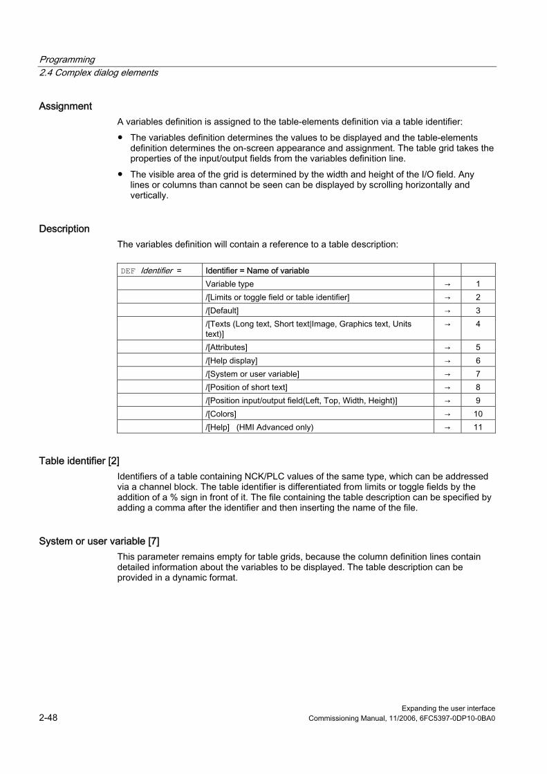
Programming 2.4 Complex dialog elements
Expanding the user interface 2-48 Commissioning Manual, 11/2006, 6FC5397-0DP10-0BA0
Assignment A variables definition is assigned to the table-elements definition via a table identifier: ● The variables definition determines the values to be displayed and the table-elements
definition determines the on-screen appearance and assignment. The table grid takes the properties of the input/output fields from the variables definition line.
● The visible area of the grid is determined by the width and height of the I/O field. Any lines or columns than cannot be seen can be displayed by scrolling horizontally and vertically.
Description The variables definition will contain a reference to a table description:
DEF Identifier = Identifier = Name of variable Variable type → 1 /[Limits or toggle field or table identifier] → 2 /[Default] → 3 /[Texts (Long text, Short text|Image, Graphics text, Units
text)] → 4
/[Attributes] → 5 /[Help display] → 6 /[System or user variable] → 7 /[Position of short text] → 8 /[Position input/output field(Left, Top, Width, Height)] → 9 /[Colors] → 10 /[Help] (HMI Advanced only) → 11
Table identifier [2] Identifiers of a table containing NCK/PLC values of the same type, which can be addressed via a channel block. The table identifier is differentiated from limits or toggle fields by the addition of a % sign in front of it. The file containing the table description can be specified by adding a comma after the identifier and then inserting the name of the file.
System or user variable [7] This parameter remains empty for table grids, because the column definition lines contain detailed information about the variables to be displayed. The table description can be provided in a dynamic format.

Programming 2.4 Complex dialog elements
Expanding the user interface Commissioning Manual, 11/2006, 6FC5397-0DP10-0BA0 2-49
2.4.6 Defining table grids
Description The table block comprises: ● Header ● 1 to n column descriptions
Programming
Syntax: //G(Table identifier/Table type/Number of lines/ [Fixed line attribute],[Fixed column attribute])
Description: Defines table grids Parameters: Table identifiers The table identifier is used without a leading % sign.
It can only be used once in a dialog. Table type 0 (default) Table for PLC or user data
(NCK- and channel-specific data)
1 and others, reserved No. of lines Number of lines including header The fixed line or fixed column is not scrolled. The
number of columns is the number of columns configured.
Fixed line attribute 1:0:
Active Not active
Fixed column attribute
1:0:
Active Not active
2.4.7 Defining columns
Description For table grids, it is advisable to use variables with an index. For PLC or NC variables, the index number is of significance with one or more indices. The values displayed in a grid can be modified directly by the end user within the restrictions of the rights granted by the attributes and within any limits defined.

Programming 2.4 Complex dialog elements
Expanding the user interface 2-50 Commissioning Manual, 11/2006, 6FC5397-0DP10-0BA0
Programming
Syntax: (Type/Limits/Empty/Long text,column header/Attributes/Help display/ System or user variable/Column width/Offset1, Offset2, Offset3)
Description: Defines columns Parameters: Similar to variables Type Data type Limits Limit value MIN, limit value MAX Long text, column
header
Attributes Help display System or user
variable The PLC or NC variables should be entered in double quotation marks.
Column width Entry in pixels. Offset The increments to be used to accumulate each
index in order to fill the column are specified in the assigned offset parameter: • Offset1: Step width for the 1st index • Offset2: Step width for the 2nd index • Offset3: Step width for the 3rd index
Variable of type STRING If the variable is a STRING type variable, the length must be specified in the type, e.g., DEF CHAN STRING [16] TEXT[41]. The column definition for the CHAN variable, therefore, starts, e.g., (S16/... ).
Column header from text file The column header can be entered as text or text numbers ($8xxxx) and is not scrolled.
Modifying column properties The column properties, which can be modified dynamically (written) are: ● Limits (min,max), ● Column header (st), ● Attributes (wr, ac and li), ● Help display (hlp) and ● OPI-Variable (var). Column properties are modified via the variable identifier in the definition line and the column index (starting at 1). Example: VAR1[1].st="Column 1"
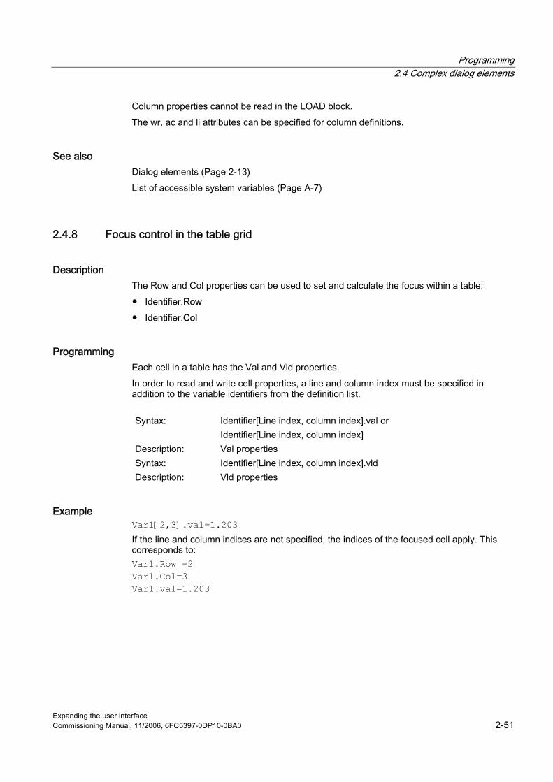
Programming 2.4 Complex dialog elements
Expanding the user interface Commissioning Manual, 11/2006, 6FC5397-0DP10-0BA0 2-51
Column properties cannot be read in the LOAD block. The wr, ac and li attributes can be specified for column definitions.
See also Dialog elements (Page 2-13) List of accessible system variables (Page A-7)
2.4.8 Focus control in the table grid
Description The Row and Col properties can be used to set and calculate the focus within a table: ● Identifier.Row ● Identifier.Col
Programming Each cell in a table has the Val and Vld properties. In order to read and write cell properties, a line and column index must be specified in addition to the variable identifiers from the definition list.
Syntax: Identifier[Line index, column index].val or
Identifier[Line index, column index] Description: Val properties Syntax: Identifier[Line index, column index].vld Description: Vld properties
Example Var1[2,3].val=1.203 If the line and column indices are not specified, the indices of the focused cell apply. This corresponds to: Var1.Row =2 Var1.Col=3 Var1.val=1.203

Programming 2.4 Complex dialog elements
Expanding the user interface 2-52 Commissioning Manual, 11/2006, 6FC5397-0DP10-0BA0
2.4.9 Example Defining columns
Overview The next three examples show the assignment between cells and PLC variables in a standard table (table type=0).
Example 1: The first line shows the column headers:
//G(MB_TAB/0/4/,1)
(I///,"MB 1 to MB 3"///"MB1"/100/1)
(I///,"MB 4 to MB 6"///"MB4"/100/1)
Result:
MB 1 to MB 3 MB 4 to MB 6 Value(MB1) Value(MB4) Value(MB2) Value(MB5) Value(MB3) Value(MB6)
Example 2: Offset > 1 in the column definition; this results in the following lines and column assignments:
//G(MB_TAB/0/4/,1)
(I///," MB1, MB3, MB5"///"MB1"/100/2)
(I///," MB2, MB4, MB6"/// "MB2"/100/2)
Result: In each line, the index of the variable is increased by the offset (=2).
MB1, MB3, MB5 MB2, MB4, MB6 Value(MB1) Value(MB2) Value(MB3) Value(MB4) Value(MB5) Value(MB6)
Example 3: Offset and index number in the column definition: ● In the first column, the first variable index for each line is increased by 1: Offset 1 = 1 ● In the first column, the second variable index for each line is increased by 1: Offset 2 = 1

Programming 2.4 Complex dialog elements
Expanding the user interface Commissioning Manual, 11/2006, 6FC5397-0DP10-0BA0 2-53
//G(MB_TAB/0/4/,1)
(IB///,"M1.1, M2.1, M3.1"/// "M1.1"/100/1)
(IB///,"M1.1, M1.2, M1.3"/// "M1.1"/100/,1)
Result:
M1.1, M2.1, M3.1 M1.1, M1.2, M1.3 Value(M1.1) Value(M1.1) Value(M2.1) Value(M1.2) Value(M3.1) Value(M1.3)
Other options: ● Ascending numbers can be entered in the first column:
Example: (I///,"Line"///"0"/60/1) ● Consecutive texts from the language files can be entered in the first column:
Example: (S///,"Line"///"$80000"/60/1)
2.4.10 Example Loading different table grids
Description In this example the "dummygrid" table is first assigned to variable "VAR1". Depending on the content of the R-parameter R[0], either the "grid1" or "grid2" table will be loaded in the LOAD block. The tables are defined in the same file as the variable "VAR1".
//M(SCREEN FORM1/"GRID")
DEF VAR1=(R/% dummygrid///////200,75,300,85)
HS1=("")
HS2=("")
HS3=("")
HS4=("")
HS5=("")
HS6=("")
HS7=("")
HS8=("")
VS1=("")
VS2=("")
VS3=("")
VS4=("")
VS5=("")
VS6=("")

Programming 2.4 Complex dialog elements
Expanding the user interface 2-54 Commissioning Manual, 11/2006, 6FC5397-0DP10-0BA0
VS7=("EXIT",ac7,se1)
VS8=("")
LOAD
REG[0] = RNP ("$R[0]")
IF (REG[0] == 0)
LG ("grid1", "var1")
ELSE
LG ("grid2", "var1")
ENDIF
END_LOAD
PRESS(VS7)
EXIT
END_PRESS
//END
//G(grid1/0/5/1,1) ; (Name/Type/Lines...)
(R///"Long text1","R1 to R4"/wr2//"$R[1]"/80/1)
; 1. Column, header "R1 to R4", from R1 with Offset1
(R///"Long text2","R5 to R8"/wr2//"$R[5]"/80/1)
; 2. Column from R5
(R///"Long text3","R9 to R15"/wr2//"$R[9]"/80/2)
; 3. Column from R9 with Offset2, R9 11 13 15
//END
//G(grid2/0/5/1,1) ; (Name/Type/Lines...)
(R///"Long text1","R1 to R4"/wr2//"$R[1]"/60/1)
; 1. Column, header "R1 to R4", from R1 with Offset1
(R///"Long text2","R5 to R8"/wr2//"$R[5]"/60/1)
; 2. Column from R5
(R///"Long text3","R9 to R15"/wr2//"$R[9]"/60/2)
; 3. Column from R9 with Offset2, R9 11 13 15
(R///"Long text4","R9 to R15"/wr2//"$R[9]"/60/2)
; 3. Column from R9 with Offset2, R9 11 13 15
//END
//G(dummygrid/0/5/1,1) ; (Name/Type/Lines...)
(R///"Long text1","R1 to R4"/wr2//"$R[1]"/80/1)
; 1. Column, header "R1 to R4", from R1 with Offset1
(R///"Long text2","R5 to R8"/wr2//"$R[5]"/80/1)
; 2. Column from R5
//END

Programming 2.5 Softkey menus
Expanding the user interface Commissioning Manual, 11/2006, 6FC5397-0DP10-0BA0 2-55
2.5 2.5 Softkey menus
2.5.1 Softkey description
Overview The names of the soft keys are predefined. Not all softkeys need to be assigned. HSx x 1 - 8, horizontal softkeys 1 to 8 VSy y 1 - 8, vertical softkeys 1 to 8 The term softkey menu is used to refer to all the horizontal and vertical softkeys displayed on a screen form. In addition to the existing softkey menus, it is possible to define other menus, which partially or completely overwrite the existing menus. The definition of a softkey menu (softkey menu definition block) is basically structured as follows:
Definition block Comment Chapter reference //S... ;Start identifier of softkey menu HSx=... ;Define softkeys PRESS(HSx) LM... END_PRESS
;Method start identifier ;Actions ;Method end identifier
See chapter "Methods"
//END ;End identifier of softkey menu
2.5.2 Define softkey menu
Description Properties are assigned to softkeys during definition of the softkey menu.
Programming
Syntax: //S(Identifier) ... //END
;Start identifier of softkey menu ;End identifier of softkey menu
Description: Defines softkey menu Parameters: Identifier Name of softkey menu
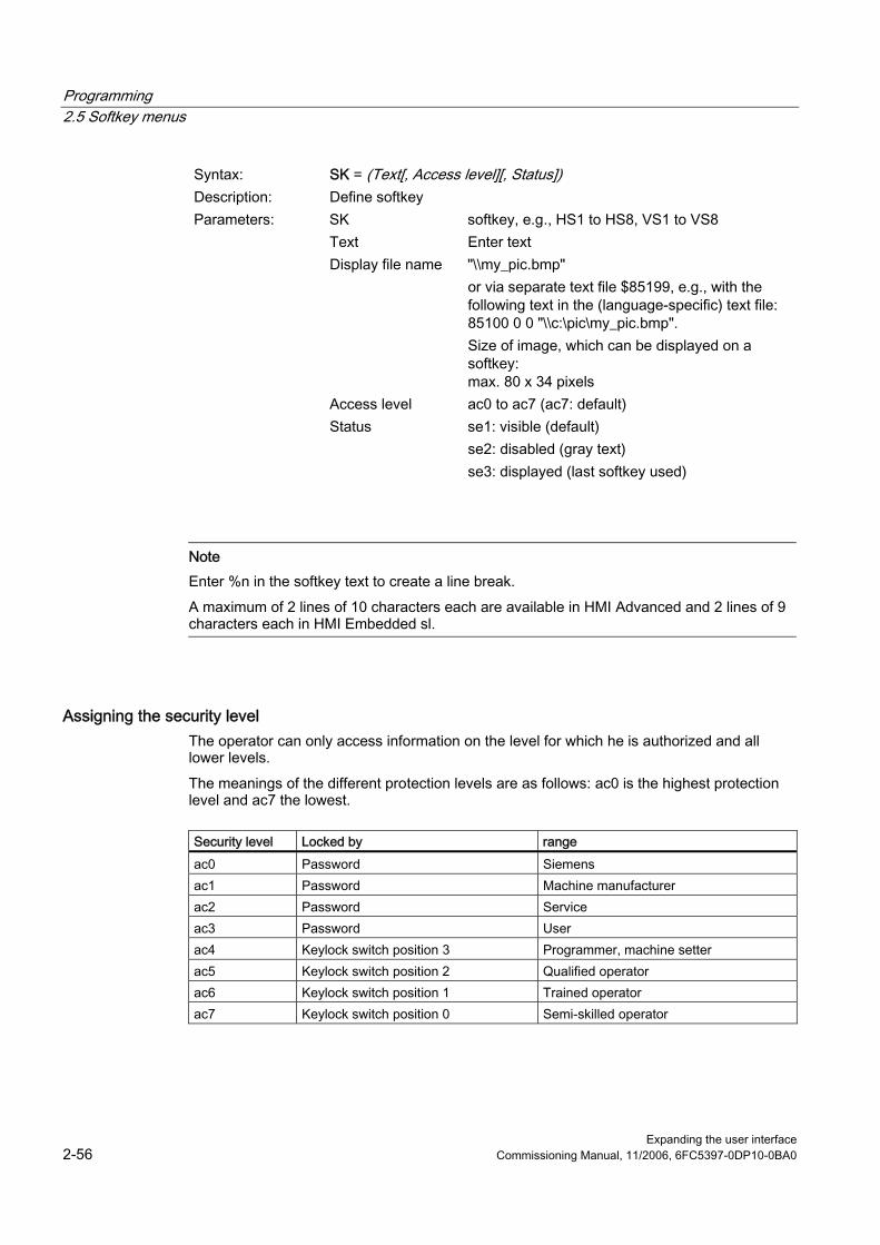
Programming 2.5 Softkey menus
Expanding the user interface 2-56 Commissioning Manual, 11/2006, 6FC5397-0DP10-0BA0
Syntax: SK = (Text[, Access level][, Status]) Description: Define softkey Parameters: SK softkey, e.g., HS1 to HS8, VS1 to VS8 Text Enter text Display file name "\\my_pic.bmp"
or via separate text file $85199, e.g., with the following text in the (language-specific) text file: 85100 0 0 "\\c:\pic\my_pic.bmp". Size of image, which can be displayed on a softkey: max. 80 x 34 pixels
Access level ac0 to ac7 (ac7: default) Status se1: visible (default)
se2: disabled (gray text) se3: displayed (last softkey used)
Note Enter %n in the softkey text to create a line break. A maximum of 2 lines of 10 characters each are available in HMI Advanced and 2 lines of 9 characters each in HMI Embedded sl.
Assigning the security level The operator can only access information on the level for which he is authorized and all lower levels. The meanings of the different protection levels are as follows: ac0 is the highest protection level and ac7 the lowest.
Security level Locked by range ac0 Password Siemens ac1 Password Machine manufacturer ac2 Password Service ac3 Password User ac4 Keylock switch position 3 Programmer, machine setter ac5 Keylock switch position 2 Qualified operator ac6 Keylock switch position 1 Trained operator ac7 Keylock switch position 0 Semi-skilled operator

Programming 2.5 Softkey menus
Expanding the user interface Commissioning Manual, 11/2006, 6FC5397-0DP10-0BA0 2-57
Example
//S(Menu1) ; Start identifier of softkey menu
HS1=("NEW",ac6,se2) ; Define softkey HS1, assign the label "OK", security level 6 and the status "disabled"
HS3=("\\bild1.bmp") ; Assign a graphic to the softkey
HS5=("Exit")
VS2=("Subscreen")
VS3=($85011, ac7, se2)
VS7=("Abort", ac1, se3) ; Define softkey HS1, assign the label "Cancel", security level 1 and the status "displayed".
VS8=("OK", ac6, se1) Define softkey VS8, assign the label "OK", security level 6 and the status "visible"
PRESS(HS1) ; Method start identifier
HS1.st="Calculate" ; Assign a label text to the softkey
...
END_PRESS ; Method end identifier
PRESS(RECALL) ; Method start identifier
LM("Screen form21") ; Load dialog
END_PRESS ; Method end identifier
//END ; Softkey menu end identifier
<RECALL> key In addition to the horizontal and vertical softkeys, a <RECALL> key is also available. In contrast to the softkeys, the RECALL key does not need to be defined. The "Status" and "Access Level" properties can be assigned to the key during runtime. If you do not assign any action (function, calculation of variables, property changes) to <RECALL>, you can use it to exit newly configured user interfaces and return to the standard application.
Example
PRESS(RECALL)
RECALL.ac = 1
LM("Screen form5")
END_PRESS
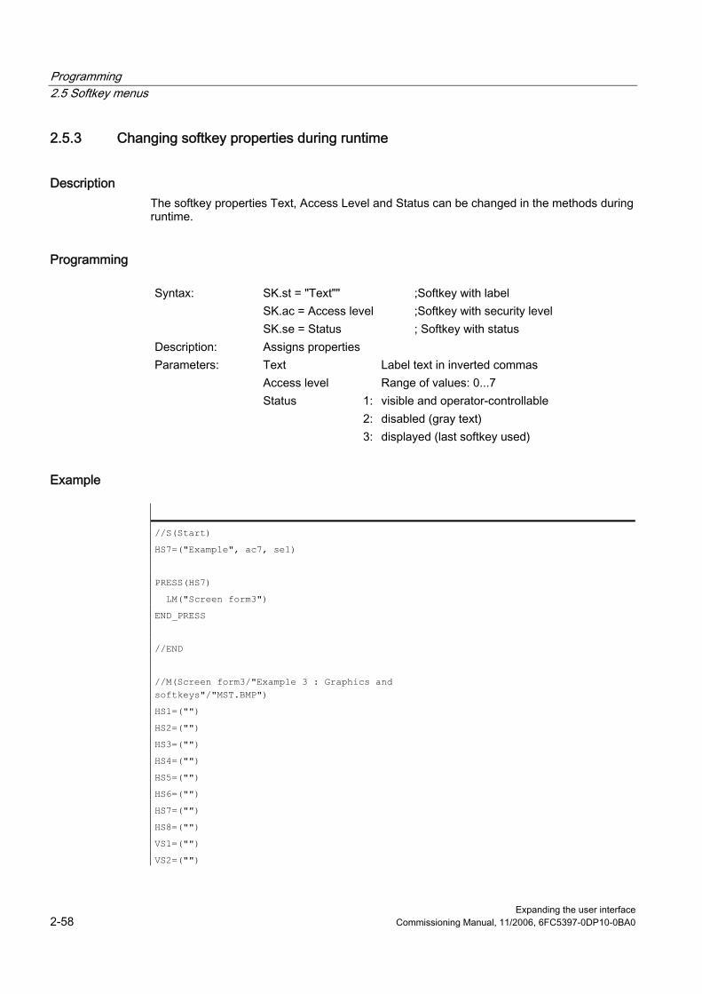
Programming 2.5 Softkey menus
Expanding the user interface 2-58 Commissioning Manual, 11/2006, 6FC5397-0DP10-0BA0
2.5.3 Changing softkey properties during runtime
Description The softkey properties Text, Access Level and Status can be changed in the methods during runtime.
Programming
Syntax: SK.st = "Text"" SK.ac = Access level SK.se = Status
;Softkey with label ;Softkey with security level ; Softkey with status
Description: Assigns properties Parameters: Text Label text in inverted commas Access level Range of values: 0...7 Status 1:
2:3:
visible and operator-controllable disabled (gray text) displayed (last softkey used)
Example
//S(Start)
HS7=("Example", ac7, se1)
PRESS(HS7)
LM("Screen form3")
END_PRESS
//END
//M(Screen form3/"Example 3 : Graphics and softkeys"/"MST.BMP")
HS1=("")
HS2=("")
HS3=("")
HS4=("")
HS5=("")
HS6=("")
HS7=("")
HS8=("")
VS1=("")
VS2=("")
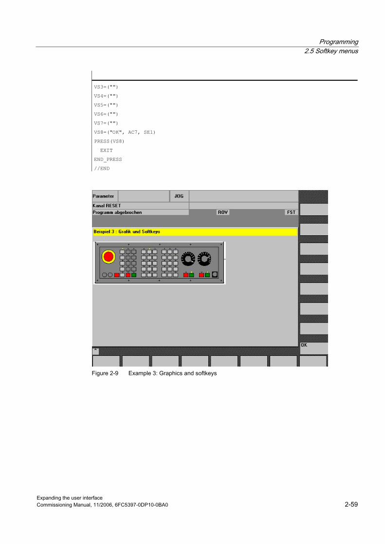
Programming 2.5 Softkey menus
Expanding the user interface Commissioning Manual, 11/2006, 6FC5397-0DP10-0BA0 2-59
VS3=("")
VS4=("")
VS5=("")
VS6=("")
VS7=("")
VS8=("OK", AC7, SE1)
PRESS(VS8)
EXIT
END_PRESS
//END
Figure 2-9 Example 3: Graphics and softkeys
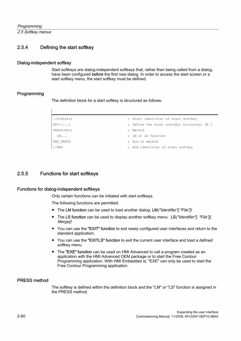
Programming 2.5 Softkey menus
Expanding the user interface 2-60 Commissioning Manual, 11/2006, 6FC5397-0DP10-0BA0
2.5.4 Defining the start softkey
Dialog-independent softkey Start softkeys are dialog-independent softkeys that, rather than being called from a dialog, have been configured before the first new dialog. In order to access the start screen or a start softkey menu, the start softkey must be defined.
Programming The definition block for a start softkey is structured as follows:
//S(Start) ; Start identifier of start softkey
HS1=(...) ; Define the start softkey: horizontal SK 1
PRESS(HS1) ; Method
LM... ; LM or LS function
END_PRESS ; End of method
//END ; End identifier of start softkey
2.5.5 Functions for start softkeys
Functions for dialog-independent softkeys Only certain functions can be initiated with start softkeys. The following functions are permitted: ● The LM function can be used to load another dialog: LM("Identifier"[,"File"]) ● The LS function can be used to display another softkey menu: LS("Identifier"[, "File"][,
Merge]) ● You can use the "EXIT" function to exit newly configured user interfaces and return to the
standard application. ● You can use the "EXITLS" function to exit the current user interface and load a defined
softkey menu. ● The "EXE" function can be used on HMI Advanced to call a program created as an
application with the HMI Advanced OEM package or to start the Free Contour Programming application. With HMI Embedded sl, "EXE" can only be used to start the Free Contour Programming application.
PRESS method The softkey is defined within the definition block and the "LM" or "LS" function is assigned in the PRESS method.
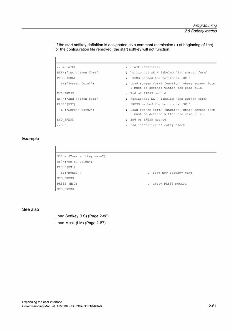
Programming 2.5 Softkey menus
Expanding the user interface Commissioning Manual, 11/2006, 6FC5397-0DP10-0BA0 2-61
If the start softkey definition is designated as a comment (semicolon (;) at beginning of line) or the configuration file removed, the start softkey will not function.
//S(Start) ; Start identifier
HS6=("1st screen form") ; horizontal SK 6 labeled "1st screen form"
PRESS(HS6) ; PRESS method for horizontal SK 6
LM("Screen form1") ; Load screen form1 function, where screen form 1 must be defined within the same file.
END_PRESS ; End of PRESS method
HS7=("2nd screen form") ; horizontal SK 7 labeled "2nd screen form"
PRESS(HS7) ; PRESS method for horizontal SK 7
LM("Screen form2") ; Load screen form2 function, where screen form 2 must be defined within the same file.
END_PRESS ; End of PRESS method
//END ; End identifier of entry block
Example
HS1 = ("new softkey menu")
HS2=("no function")
PRESS(HS1)
LS("Menu1") ; load new softkey menu
END_PRESS
PRESS (HS2) ; empty PRESS method
END_PRESS
See also Load Softkey (LS) (Page 2-88) Load Mask (LM) (Page 2-87)

Programming 2.6 Methods
Expanding the user interface 2-62 Commissioning Manual, 11/2006, 6FC5397-0DP10-0BA0
2.6 2.6 Methods
Overview Various types of event (exit input field, actuate softkey) can initiate specific actions in dialogs and dialog-dependent softkey menus (softkey menus that are called from a newly configured dialog). These actions are configured in methods. The following table shows the basic principle used to program a method:
Definition block Comment Chapter reference PRESS(HS1) ;Method start identifier LM... LS...
;Functions See chapter "Functions"
Var1.st = ... ;Changing properties see chapter "Softkey menu" and chapter "Dialog elements"
Var2 = Var3 + Var4 ... EXIT
;Calculation with variables See chapter "Defining variables"
END_PRESS ;Method end identifier
2.6.1 CHANGE
Description CHANGE methods are executed if a variable value changes, i.e., variable calculations that are performed as soon as a variable value changes are configured within a CHANGE method. There are two types of CHANGE method, i.e., element-specific and global: ● The element-specific CHANGE method is executed if the value of a specified variable
changes. If a system or user variable is assigned to a variable, cyclic updating of the variable value can be configured in a CHANGE method.
● The global CHANGE method is executed if the value of any variable changes and no element-specific CHANGE method has been configured.
"Element-specific" programming
Syntax: CHANGE(Identifier) ... END_CHANGE
Description: Changes the value of a specific variable Parameters: Identifier Name of the variable

Programming 2.6 Methods
Expanding the user interface Commissioning Manual, 11/2006, 6FC5397-0DP10-0BA0 2-63
Example
DEF VAR1=(S//////"DB20.DBB1") ; A system variable is assigned to Var1
CHANGE(VAR1)
IF VAR1.Val <> 1
VAR1.st="Tool OK!" ; If the value of the system variable ≠ 1, the short text of the variable states: Tool OK!
otto=1
ELSE
VAR1.st="Attention: Error!" ; If the value of the system variable = 1, the short text of the variable states: Attention: Error!
otto=2
ENDIF
VAR2.Var=2
END_CHANGE
"Global" programming
Syntax: CHANGE() ... END_CHANGE
Description: Changes any variable value Parameters: - None -
Example
CHANGE()
EXIT ; If any of the variable values change, the dialog will be terminated.
END_CHANGE

Programming 2.6 Methods
Expanding the user interface 2-64 Commissioning Manual, 11/2006, 6FC5397-0DP10-0BA0
2.6.2 FOCUS
Description The FOCUS method is executed if the focus (cursor) is positioned on another field in the dialog. The FOCUS method must not be initiated as a result of a navigation event. The cursor may only be moved in softkey PRESS blocks, CHANGE blocks, etc. Responses to cursor movements are are predefined and cannot be modified.
Note Within the FOCUS block, it is not possible to select a different variable, nor can a new dialog be loaded.
Programming
Syntax: FOCUS ... END_FOCUS
Description: Positions the cursor Parameters: - None -
Example
FOCUS
DLGL("The focus has been placed on variable" << FOC << ".) º º
END_FOCUS
2.6.3 LOAD GRID
Description The table description can be made available dynamically within the LOAD block using the LG method. In order to assign a table using the LG method, the variable must have already been defined as a grid variable and cross-referenced to an existing, valid table.

Programming 2.6 Methods
Expanding the user interface Commissioning Manual, 11/2006, 6FC5397-0DP10-0BA0 2-65
Programming
Syntax: LG (Grid name, Variable name [,File name]) Description: Loads a table Parameters: Grid name Name of the table (grid) in inverted commas Variable name Name of the variable to which the table is to be
assigned, in inverted commas File name Name of the file in which the table (grid) is defined,
in inverted commas. Only needs to be specified if the table is not defined within the file that also contains the definition of the variable.
2.6.4 LOAD
Description The LOAD method is executed after the variable and softkey definitions (DEF Var1= ..., HS1= ...) have been interpreted. At this time, the dialog is not yet displayed.
Programming
Syntax: LOAD ... END_LOAD
Description: Download Parameters: - None -
Example
LOAD ; Start identifier
Screen form1.Hd = $85111 ; Assign text for dialog header from language file
VAR1.Min = 0 ; Assign MIN variable limit
VAR1.Max = 1000 ; Assign MAX variable limit
END_LOAD ; End code

Programming 2.6 Methods
Expanding the user interface 2-66 Commissioning Manual, 11/2006, 6FC5397-0DP10-0BA0
2.6.5 UNLOAD
Description The UNLOAD method is executed before a dialog is unloaded.
Programming
Syntax: UNLOAD ... END_UNLOAD
Description: Unload Parameters: - None -
Example
UNLOAD
REG[1] = VAR1 ; Save variable in register
END_UNLOAD
2.6.6 OUTPUT
Description The OUTPUT method is executed if the "GC" function is called.Variables and Help variables are configured as an NC code in an OUTPUT method. The individual elements in a code line are linked by means of blanks.
Note The NC code can be generated in an extra file by means of file functions and transferred to the NC.

Programming 2.6 Methods
Expanding the user interface Commissioning Manual, 11/2006, 6FC5397-0DP10-0BA0 2-67
Programming
Syntax: OUTPUT (Identifier) ... END_OUTPUT
Description: Outputs variables in the NC program. Parameters: Identifier Name of OUTPUT method
Block numbers and skip identifiers The OUTPUT block must not contain line numbers or skip identifiers if you wish to keep the line numbers and hide markings directly set with active program support in the parts program in case of recompilations. Editor changes in the parts program produce the following response:
Condition Response Number of blocks remains unchanged. Block numbers are retained. Number of blocks is reduced. The highest block numbers are canceled. Number of blocks is increased. New blocks are not numbered.
Example
OUTPUT(CODE1)
"CYCLE82(" Var1.val "," Var2.val "," Var3.val ","Var4.val "," Var5.val "," Var6.val ")"
END_OUTPUT
2.6.7 PRESS
Description The PRESS method is executed when the corresponding softkey is pressed.
Programming
Syntax: PRESS(softkey) ... END_PRESS
Identifiers: Pressing a softkey
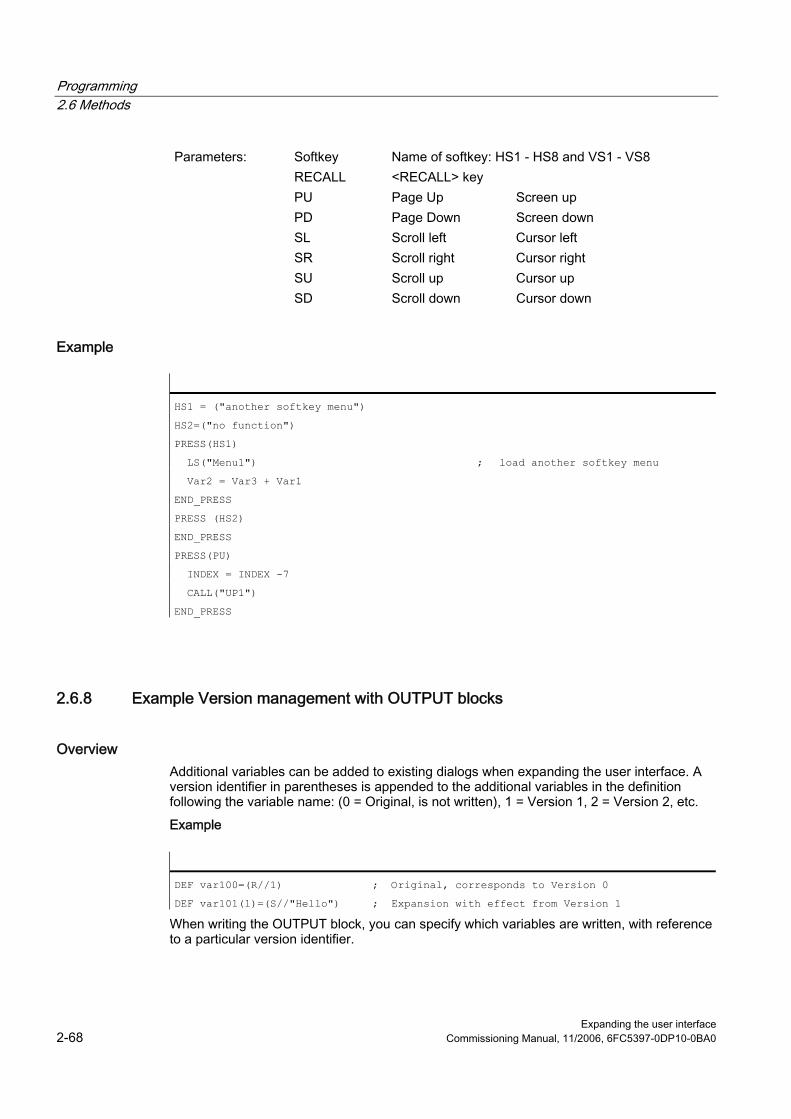
Programming 2.6 Methods
Expanding the user interface 2-68 Commissioning Manual, 11/2006, 6FC5397-0DP10-0BA0
Parameters: Softkey Name of softkey: HS1 - HS8 and VS1 - VS8 RECALL <RECALL> key PU Page Up Screen up PD Page Down Screen down SL Scroll left Cursor left SR Scroll right Cursor right SU Scroll up Cursor up SD Scroll down Cursor down
Example
HS1 = ("another softkey menu")
HS2=("no function")
PRESS(HS1)
LS("Menu1") ; load another softkey menu
Var2 = Var3 + Var1
END_PRESS
PRESS (HS2)
END_PRESS
PRESS(PU)
INDEX = INDEX -7
CALL("UP1")
END_PRESS
2.6.8 Example Version management with OUTPUT blocks
Overview Additional variables can be added to existing dialogs when expanding the user interface. A version identifier in parentheses is appended to the additional variables in the definition following the variable name: (0 = Original, is not written), 1 = Version 1, 2 = Version 2, etc. Example
DEF var100=(R//1) ; Original, corresponds to Version 0
DEF var101(1)=(S//"Hello") ; Expansion with effect from Version 1
When writing the OUTPUT block, you can specify which variables are written, with reference to a particular version identifier.
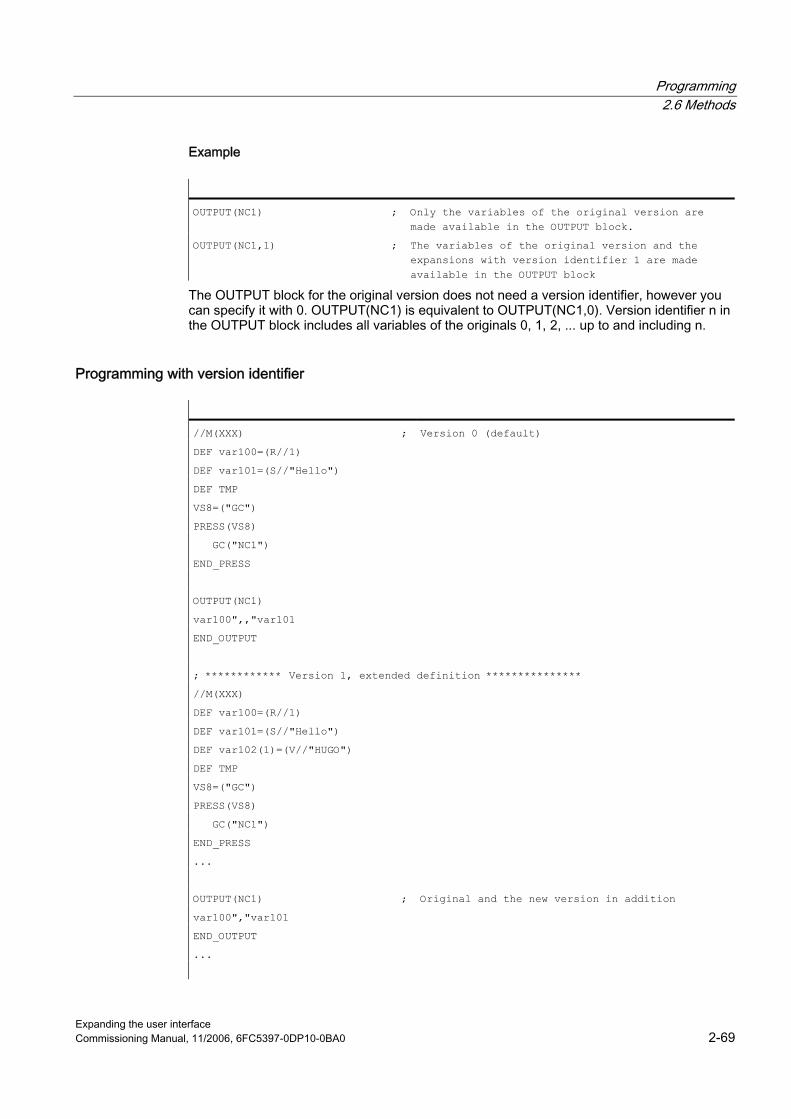
Programming 2.6 Methods
Expanding the user interface Commissioning Manual, 11/2006, 6FC5397-0DP10-0BA0 2-69
Example
OUTPUT(NC1) ; Only the variables of the original version are made available in the OUTPUT block.
OUTPUT(NC1,1) ; The variables of the original version and the expansions with version identifier 1 are made available in the OUTPUT block
The OUTPUT block for the original version does not need a version identifier, however you can specify it with 0. OUTPUT(NC1) is equivalent to OUTPUT(NC1,0). Version identifier n in the OUTPUT block includes all variables of the originals 0, 1, 2, ... up to and including n.
Programming with version identifier
//M(XXX) ; Version 0 (default)
DEF var100=(R//1)
DEF var101=(S//"Hello")
DEF TMP
VS8=("GC")
PRESS(VS8)
GC("NC1")
END_PRESS
OUTPUT(NC1)
var100",,"var101
END_OUTPUT
; ************ Version 1, extended definition ***************
//M(XXX)
DEF var100=(R//1)
DEF var101=(S//"Hello")
DEF var102(1)=(V//"HUGO")
DEF TMP
VS8=("GC")
PRESS(VS8)
GC("NC1")
END_PRESS
...
OUTPUT(NC1) ; Original and the new version in addition
var100","var101
END_OUTPUT
...

Programming 2.7 Functions
Expanding the user interface 2-70 Commissioning Manual, 11/2006, 6FC5397-0DP10-0BA0
OUTPUT(NC1,1) ; Version 1
var100","var101"," var102
END_OUTPUT
2.7 2.7 Functions
Overview A variety of functions are available in dialogs and dialog-dependent softkey menus. These can be activated by specific events (exit input field, actuate softkey) and configured in methods.
Subroutines Repeatedly used configuring instructions or others, which define the process for a particular operation can be configured in subprograms. Subprograms can be loaded into the main program or other subprograms at any time and executed as often as necessary, i.e., the instructions they contain do not need to be configured repeatedly. The definition blocks of the dialogs/softkey menu constitute a main program.
PI services The PI_SERVICE function can be used to start PI Services (Program Invocation Services) from the PLC in the NC area.
External functions (only HMI Advanced) Additional, user-specific functions can be integrated by means of external functions. External functions are stored in a DLL file and identified by an entry in the definition lines of the configuration file.
See also List of Pl services (Page A-17) External functions (only HMI Advanced) (Page 2-105)
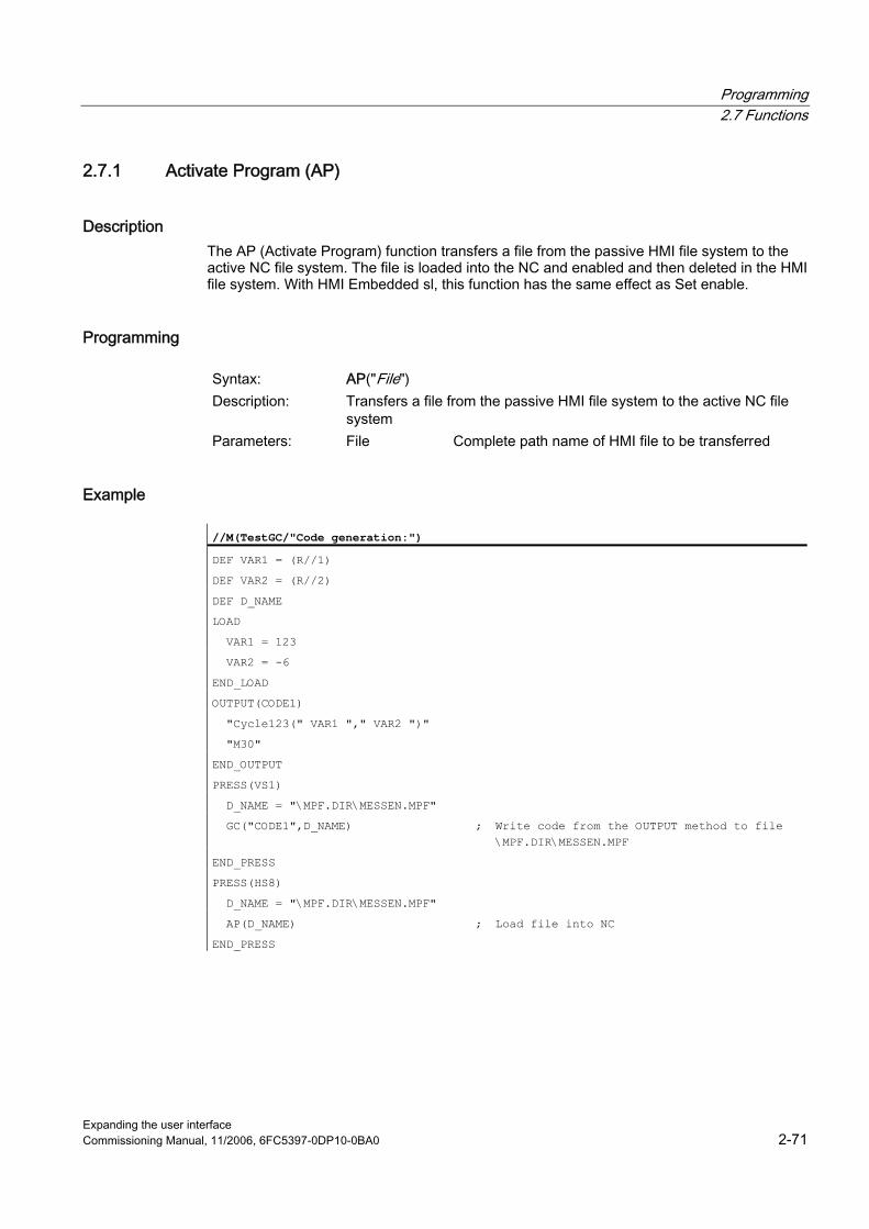
Programming 2.7 Functions
Expanding the user interface Commissioning Manual, 11/2006, 6FC5397-0DP10-0BA0 2-71
2.7.1 Activate Program (AP)
Description The AP (Activate Program) function transfers a file from the passive HMI file system to the active NC file system. The file is loaded into the NC and enabled and then deleted in the HMI file system. With HMI Embedded sl, this function has the same effect as Set enable.
Programming
Syntax: AP("File") Description: Transfers a file from the passive HMI file system to the active NC file
system Parameters: File Complete path name of HMI file to be transferred
Example
//M(TestGC/"Code generation:")
DEF VAR1 = (R//1)
DEF VAR2 = (R//2)
DEF D_NAME
LOAD
VAR1 = 123
VAR2 = -6
END_LOAD
OUTPUT(CODE1)
"Cycle123(" VAR1 "," VAR2 ")"
"M30"
END_OUTPUT
PRESS(VS1)
D_NAME = "\MPF.DIR\MESSEN.MPF"
GC("CODE1",D_NAME) ; Write code from the OUTPUT method to file \MPF.DIR\MESSEN.MPF
END_PRESS
PRESS(HS8)
D_NAME = "\MPF.DIR\MESSEN.MPF"
AP(D_NAME) ; Load file into NC
END_PRESS
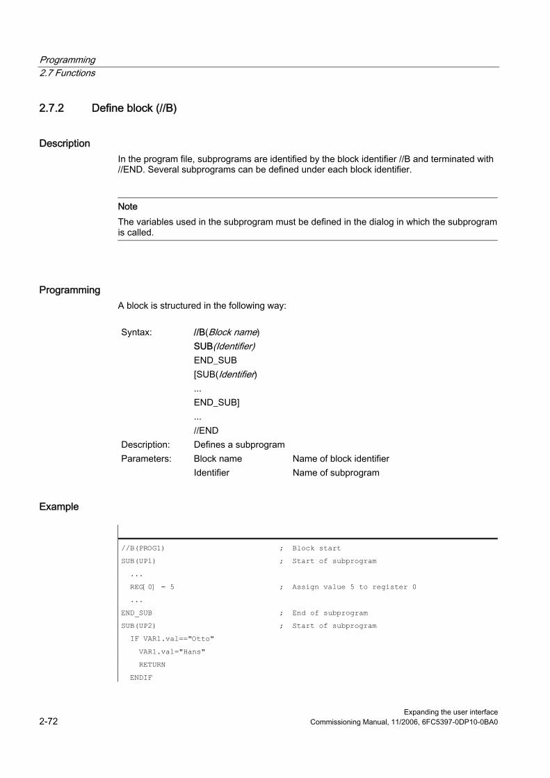
Programming 2.7 Functions
Expanding the user interface 2-72 Commissioning Manual, 11/2006, 6FC5397-0DP10-0BA0
2.7.2 Define block (//B)
Description In the program file, subprograms are identified by the block identifier //B and terminated with //END. Several subprograms can be defined under each block identifier.
Note The variables used in the subprogram must be defined in the dialog in which the subprogram is called.
Programming A block is structured in the following way:
Syntax: //B(Block name)
SUB(Identifier) END_SUB [SUB(Identifier) ... END_SUB] ... //END
Description: Defines a subprogram Parameters: Block name Name of block identifier Identifier Name of subprogram
Example
//B(PROG1) ; Block start
SUB(UP1) ; Start of subprogram
...
REG[0] = 5 ; Assign value 5 to register 0�
...
END_SUB ; End of subprogram
SUB(UP2) ; Start of subprogram
IF VAR1.val=="Otto"
VAR1.val="Hans"
RETURN
ENDIF
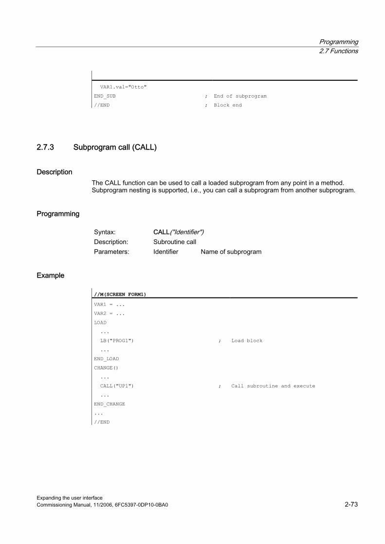
Programming 2.7 Functions
Expanding the user interface Commissioning Manual, 11/2006, 6FC5397-0DP10-0BA0 2-73
VAR1.val="Otto"
END_SUB ; End of subprogram
//END ; Block end
2.7.3 Subprogram call (CALL)
Description The CALL function can be used to call a loaded subprogram from any point in a method. Subprogram nesting is supported, i.e., you can call a subprogram from another subprogram.
Programming
Syntax: CALL("Identifier") Description: Subroutine call Parameters: Identifier Name of subprogram
Example
//M(SCREEN FORM1)�
VAR1 = ...
VAR2 = ...
LOAD
...
LB("PROG1") ; Load block
...
END_LOAD
CHANGE()
...
CALL("UP1") ; Call subroutine and execute
...
END_CHANGE
...
//END
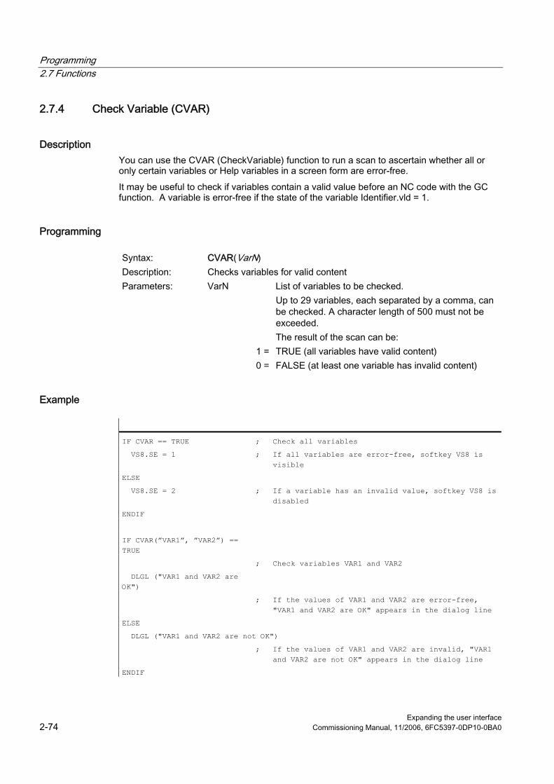
Programming 2.7 Functions
Expanding the user interface 2-74 Commissioning Manual, 11/2006, 6FC5397-0DP10-0BA0
2.7.4 Check Variable (CVAR)
Description You can use the CVAR (CheckVariable) function to run a scan to ascertain whether all or only certain variables or Help variables in a screen form are error-free. It may be useful to check if variables contain a valid value before an NC code with the GC function. A variable is error-free if the state of the variable Identifier.vld = 1.
Programming
Syntax: CVAR(VarN) Description: Checks variables for valid content Parameters: VarN List of variables to be checked.
Up to 29 variables, each separated by a comma, can be checked. A character length of 500 must not be exceeded. The result of the scan can be:
1 = TRUE (all variables have valid content) 0 = FALSE (at least one variable has invalid content)
Example
IF CVAR == TRUE ; Check all variables
VS8.SE = 1 ; If all variables are error-free, softkey VS8 is visible
ELSE
VS8.SE = 2 ; If a variable has an invalid value, softkey VS8 is disabled
ENDIF
IF CVAR(”VAR1”, ”VAR2”) == TRUE
; Check variables VAR1 and VAR2
DLGL ("VAR1 and VAR2 are OK")
; If the values of VAR1 and VAR2 are error-free, "VAR1 and VAR2 are OK" appears in the dialog line
ELSE
DLGL ("VAR1 and VAR2 are not OK")
; If the values of VAR1 and VAR2 are invalid, "VAR1 and VAR2 are not OK" appears in the dialog line
ENDIF

Programming 2.7 Functions
Expanding the user interface Commissioning Manual, 11/2006, 6FC5397-0DP10-0BA0 2-75
2.7.5 Copy Program (CP)
Description The CP (Copy Program) function copies files within the HMI file system or NC file system.
Note With HMI Embedded on NCU, copying is only possible within the NC file system.
Programming
Syntax: CP("Source file", "Target file") Description: Copies a file Parameters: Source file Complete path to the source file Target file Complete path data of the target file
Example
CP("\MPF.DIR\CFI.MPF ", "\spf.dir\cfi.nc")
2.7.6 Dialog line (DLGL)
Description It is possible to configure short texts (messages or input tips) for output in the dialog line of the dialog in response to certain situations. Possible number of characters in the default font size: ● HMI Embedded sl: approx. 50 ● HMI Advanced: approx. 100
Programming
Syntax: DLGL("String") Description: Outputs text in the dialog line Parameters: String Text, which is displayed in the dialog line

Programming 2.7 Functions
Expanding the user interface 2-76 Commissioning Manual, 11/2006, 6FC5397-0DP10-0BA0
Example
IF Var1 > Var2
DLGL("Value too large!") ; The text "Value too large!" appears in the dialog line if variable1 > variable2.
ENDIF
2.7.7 Delete Program (DP)
Description The DP (Delete Program) function deletes a file from the passive HMI or active NC file system.
Programming
Syntax: DP("File") Description: Delete file Parameters: File Complete path name of file to be deleted
Example
DP("\MPF.DIR\CFI.MPF")

Programming 2.7 Functions
Expanding the user interface Commissioning Manual, 11/2006, 6FC5397-0DP10-0BA0 2-77
2.7.8 Evaluate (EVAL)
Description The EVAL function evaluates a transferred expression and then executes it. With this function, expressions can be programmed during runtime. This can be useful, for example, for indexed access operations to variables.
Programming
Syntax: EVAL(exp) Description: Evaluates an expression Parameters: exp Logic expression
Example
VAR1=(S)
VAR2=(S)
VAR3=(S)
VAR4=(S)
CHANGE()
REG[7] = EVAL("VAR"<<REG[5]) ; The expression in parentheses produces VAR3 if the value of REG[5] is equal to 3. The value of VAR3 is, therefore, assigned to REG[7].
IF REG[5] == 1
REG[7] = VAR1
ELSE
IF REG[5] == 2
REG[7] = VAR2
ELSE
IF REG[5] == 3
REG[7] = VAR3
ELSE
IF REG[5] == 4
REG[7] = VAR4
ENDIF
ENDIF
ENDIF
ENDIF
END_CHANGE
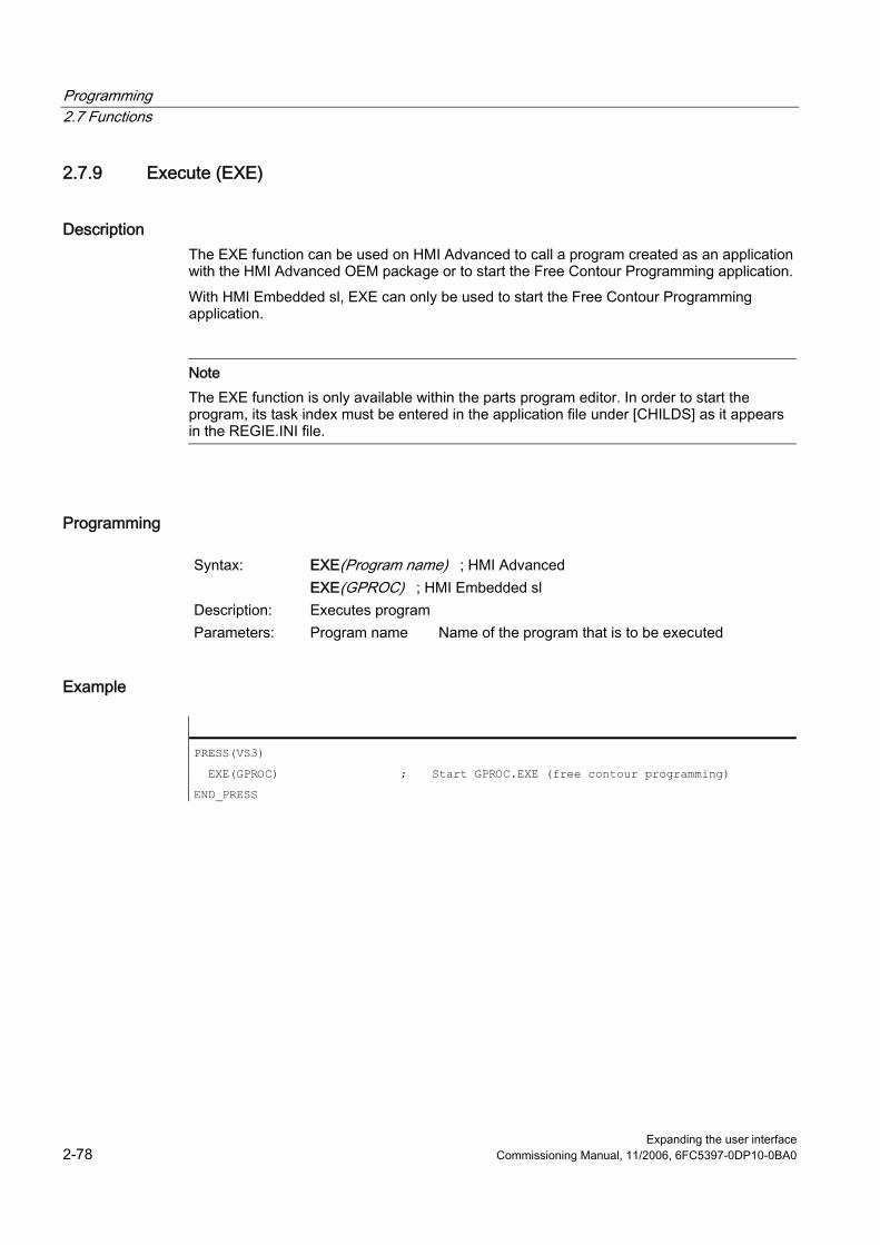
Programming 2.7 Functions
Expanding the user interface 2-78 Commissioning Manual, 11/2006, 6FC5397-0DP10-0BA0
2.7.9 Execute (EXE)
Description The EXE function can be used on HMI Advanced to call a program created as an application with the HMI Advanced OEM package or to start the Free Contour Programming application. With HMI Embedded sl, EXE can only be used to start the Free Contour Programming application.
Note The EXE function is only available within the parts program editor. In order to start the program, its task index must be entered in the application file under [CHILDS] as it appears in the REGIE.INI file.
Programming
Syntax: EXE(Program name) ; HMI Advanced EXE(GPROC) ; HMI Embedded sl
Description: Executes program Parameters: Program name Name of the program that is to be executed
Example
PRESS(VS3)
EXE(GPROC) ; Start GPROC.EXE (free contour programming)
END_PRESS
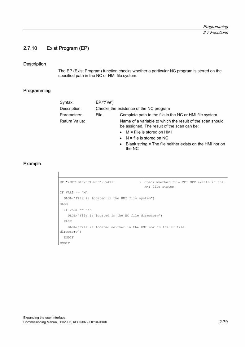
Programming 2.7 Functions
Expanding the user interface Commissioning Manual, 11/2006, 6FC5397-0DP10-0BA0 2-79
2.7.10 Exist Program (EP)
Description The EP (Exist Program) function checks whether a particular NC program is stored on the specified path in the NC or HMI file system.
Programming
Syntax: EP("File") Description: Checks the existence of the NC program Parameters: File Complete path to the file in the NC or HMI file system Return Value: Name of a variable to which the result of the scan should
be assigned. The result of the scan can be: • M = File is stored on HMI • N = file is stored on NC • Blank string = The file neither exists on the HMI nor on
the NC
Example
EP("\MPF.DIR\CFI.MPF", VAR1) ; Check whether file CFI.MPF exists in the HMI file system.
IF VAR1 == "M"
DLGL("File is located in the HMI file system")
ELSE
IF VAR1 == "N"
DLGL("File is located in the NC file directory")
ELSE
DLGL("File is located neither in the HMI nor in the NC file directory")
ENDIF
ENDIF
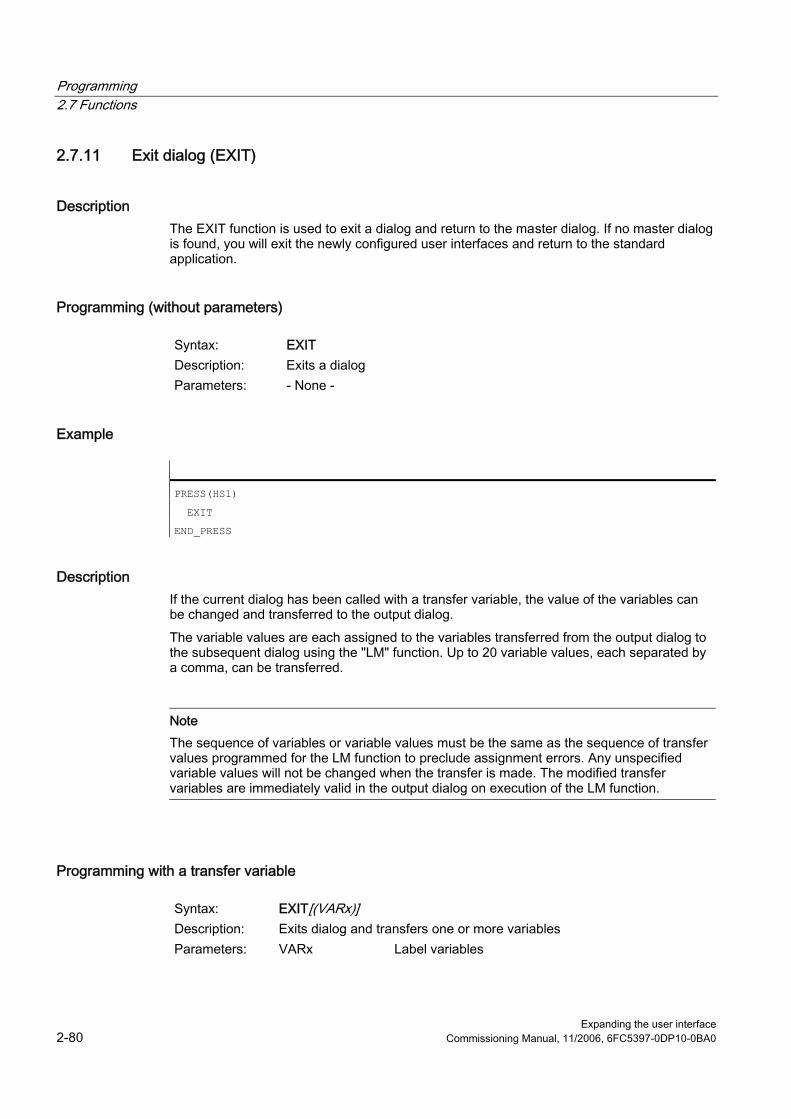
Programming 2.7 Functions
Expanding the user interface 2-80 Commissioning Manual, 11/2006, 6FC5397-0DP10-0BA0
2.7.11 Exit dialog (EXIT)
Description The EXIT function is used to exit a dialog and return to the master dialog. If no master dialog is found, you will exit the newly configured user interfaces and return to the standard application.
Programming (without parameters)
Syntax: EXIT Description: Exits a dialog Parameters: - None -
Example
PRESS(HS1)
EXIT
END_PRESS
Description If the current dialog has been called with a transfer variable, the value of the variables can be changed and transferred to the output dialog. The variable values are each assigned to the variables transferred from the output dialog to the subsequent dialog using the "LM" function. Up to 20 variable values, each separated by a comma, can be transferred.
Note The sequence of variables or variable values must be the same as the sequence of transfer values programmed for the LM function to preclude assignment errors. Any unspecified variable values will not be changed when the transfer is made. The modified transfer variables are immediately valid in the output dialog on execution of the LM function.
Programming with a transfer variable
Syntax: EXIT[(VARx)] Description: Exits dialog and transfers one or more variables Parameters: VARx Label variables
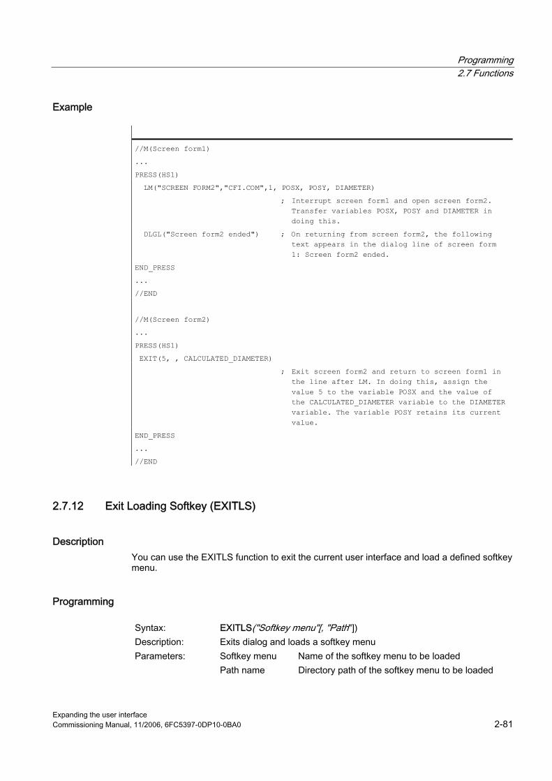
Programming 2.7 Functions
Expanding the user interface Commissioning Manual, 11/2006, 6FC5397-0DP10-0BA0 2-81
Example
//M(Screen form1)�
...
PRESS(HS1)
LM("SCREEN FORM2","CFI.COM",1, POSX, POSY, DIAMETER)
; Interrupt screen form1 and open screen form2. Transfer variables POSX, POSY and DIAMETER in doing this.
DLGL("Screen form2 ended") ; On returning from screen form2, the following text appears in the dialog line of screen form 1: Screen form2 ended.
END_PRESS
...
//END
//M(Screen form2)�
...
PRESS(HS1)
EXIT(5, , CALCULATED_DIAMETER)
; Exit screen form2 and return to screen form1 in the line after LM. In doing this, assign the value 5 to the variable POSX and the value of the CALCULATED_DIAMETER variable to the DIAMETER variable. The variable POSY retains its current value.
END_PRESS
...
//END
2.7.12 Exit Loading Softkey (EXITLS)
Description You can use the EXITLS function to exit the current user interface and load a defined softkey menu.
Programming
Syntax: EXITLS("Softkey menu"[, "Path"]) Description: Exits dialog and loads a softkey menu Parameters: Softkey menu Name of the softkey menu to be loaded Path name Directory path of the softkey menu to be loaded
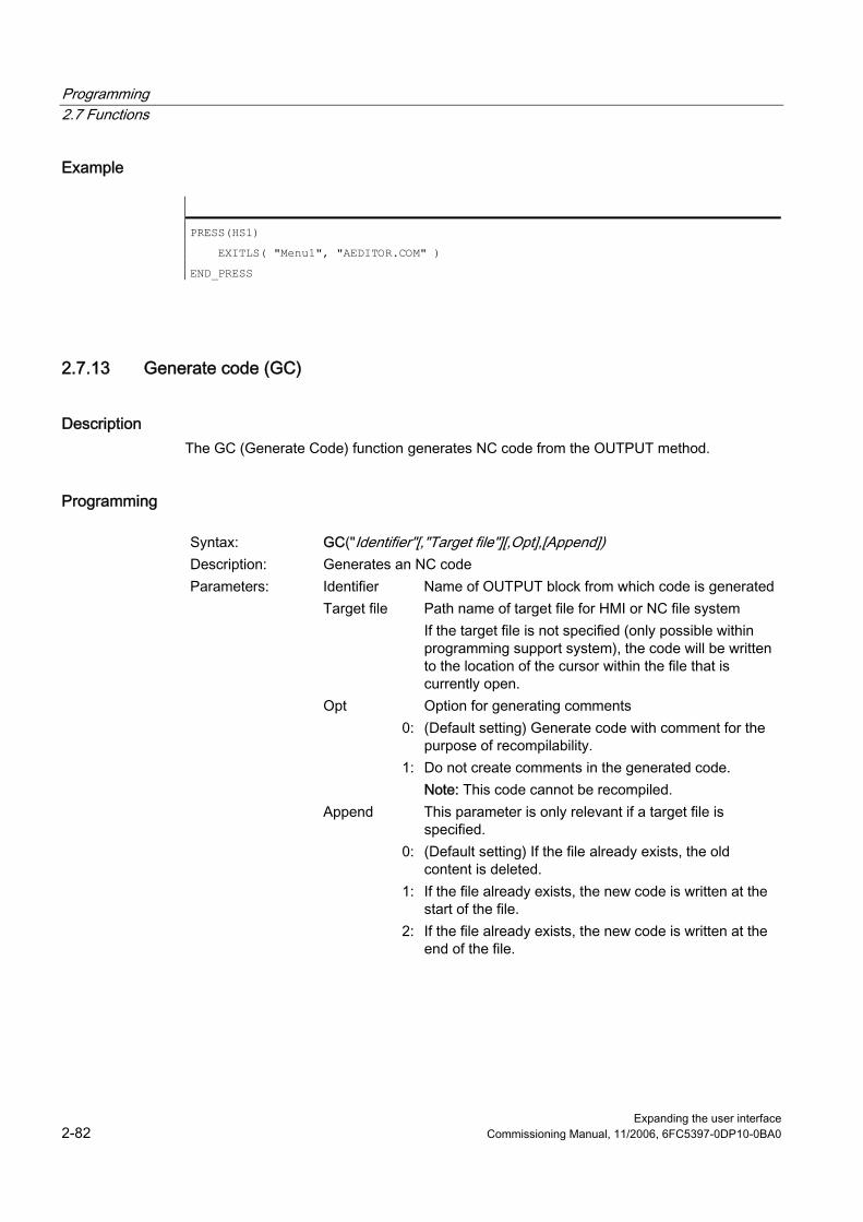
Programming 2.7 Functions
Expanding the user interface 2-82 Commissioning Manual, 11/2006, 6FC5397-0DP10-0BA0
Example
PRESS(HS1)
EXITLS( "Menu1", "AEDITOR.COM" )
END_PRESS
2.7.13 Generate code (GC)
Description The GC (Generate Code) function generates NC code from the OUTPUT method.
Programming
Syntax: GC("Identifier"[,"Target file"][,Opt],[Append]) Description: Generates an NC code Parameters: Identifier Name of OUTPUT block from which code is generated Target file Path name of target file for HMI or NC file system
If the target file is not specified (only possible within programming support system), the code will be written to the location of the cursor within the file that is currently open.
Opt Option for generating comments 0: (Default setting) Generate code with comment for the
purpose of recompilability. 1: Do not create comments in the generated code.
Note: This code cannot be recompiled. Append This parameter is only relevant if a target file is
specified. 0: (Default setting) If the file already exists, the old
content is deleted. 1: If the file already exists, the new code is written at the
start of the file. 2: If the file already exists, the new code is written at the
end of the file.

Programming 2.7 Functions
Expanding the user interface Commissioning Manual, 11/2006, 6FC5397-0DP10-0BA0 2-83
Example
//M(TestGC/"Code generation:")
DEF VAR1 = (R//1)
DEF VAR2 = (R//2)
DEF D_NAME
LOAD
VAR1 = 123
VAR2 = -6
END_LOAD
OUTPUT(CODE1)
"Cycle123(" VAR1 "," VAR2 ")"
"M30"
END_OUTPUT
PRESS(VS1)
D_NAME = "MPF.DIR\MESSEN.MPF"
GC("CODE1",D_NAME) ; Write code from OUTPUT method to file \MPF.DIR\MESSEN.MPF: Cycle123(123, -6) M30
END_PRESS
Recompile ● No entry for target file:
The GC function can only be used in the Programming Support system and writes the NC code to the file currently open in the Editor. Recompilation of the NC code is possible. If the GC function is configured without specification of a target file under "Expand user interface", an error message is output when it is executed.
● Entry for target file: The code generated from the OUTPUT block is transferred to the target file. If the target file does not already exist, it is set up in the NC file system. If the target file is stored in the HMI file system, it is stored on the hard disk (HMI Advanced only). User comment lines (information required to recompile code) are not set up, i.e., the code cannot be recompiled.
Special considerations for target file specification In principle, there are three different ways of specifying a target file: ● NC notation: /_N_MPF_DIR/_N_MY_FILE_MPF
Only possible with HMI Embedded sl. The file is created in the MPF directory on the NC.
● DH notation: /MPF.DIR\MY_FILE.MPF Possible with both HMI Advanced and HMI Embedded sl

Programming 2.7 Functions
Expanding the user interface 2-84 Commissioning Manual, 11/2006, 6FC5397-0DP10-0BA0
In the case of HMI Embedded sl, the target file specification is converted into NC notation and the file is created on the NCU. In the case of HMI Advanced or HMI Embedded WIN32, the file is created in the data management path.
● DOS notation: d:\abc\my_file.txt or \\RemoteRechner\files\my_file.txt Possible with both HMI Advanced and HMI Embedded sl The file is written to the specified directory on the hard disk or on the specified PC, provided that the directory is available on the hard disk or on a remote PC. In the case of HMI Embedded sl this notation can only be used to write to the RAM drive or to a networked PC provided that a network connection has been configured.
Note Invalid variables generate a blank string in generated NC code and an error message in the log book when they are read.
Special features of recompilation The GC function cannot be called in sub-dialogs because variables originating from master dialogs can be used in sub-dialogs. These variables would not, however, be available in response to a direct call. When generated code is processed manually with the Editor, the number of characters for values created by the code generation program must not be changed. Changing these values would make it impossible to recompile the code. Remedy: 1. Recompile 2. Make change using the configured dialog. (e. g., 99 → 101) 3. GC
See also Recompile (Page 2-96)

Programming 2.7 Functions
Expanding the user interface Commissioning Manual, 11/2006, 6FC5397-0DP10-0BA0 2-85
2.7.14 Load Array (LA)
Description The LA (Load Array) function can be used to load an array from another file.
Programming
Syntax: LA(Identifier [, File]) Description: Loads array from file Parameters: Identifier Name of array to be loaded File File in which the array is defined
Note If an array in the current configuration file must be replaced by an array from another configuration file, then both arrays must have the same name.
Example
; Extract from file maske.com
DEF VAR2 = (S/*ARR5/"Out"/,"Toggle field")
PRESS(HS5)
LA("ARR5","arrayext.com") ; Load array ARR5 from file arrayext.com
VAR2 = ARR5[0] ; "Above"/"Below"/"Right"/"Left" appears in the VAR2 toggle field
instead of "Out/In"
END_PRESS
//A(ARR5)
("Out"/"In")
//END
; Extract from file arrayext.com
//A(ARR5)
("Above"/"Below"/"Right"/"Left")
//END
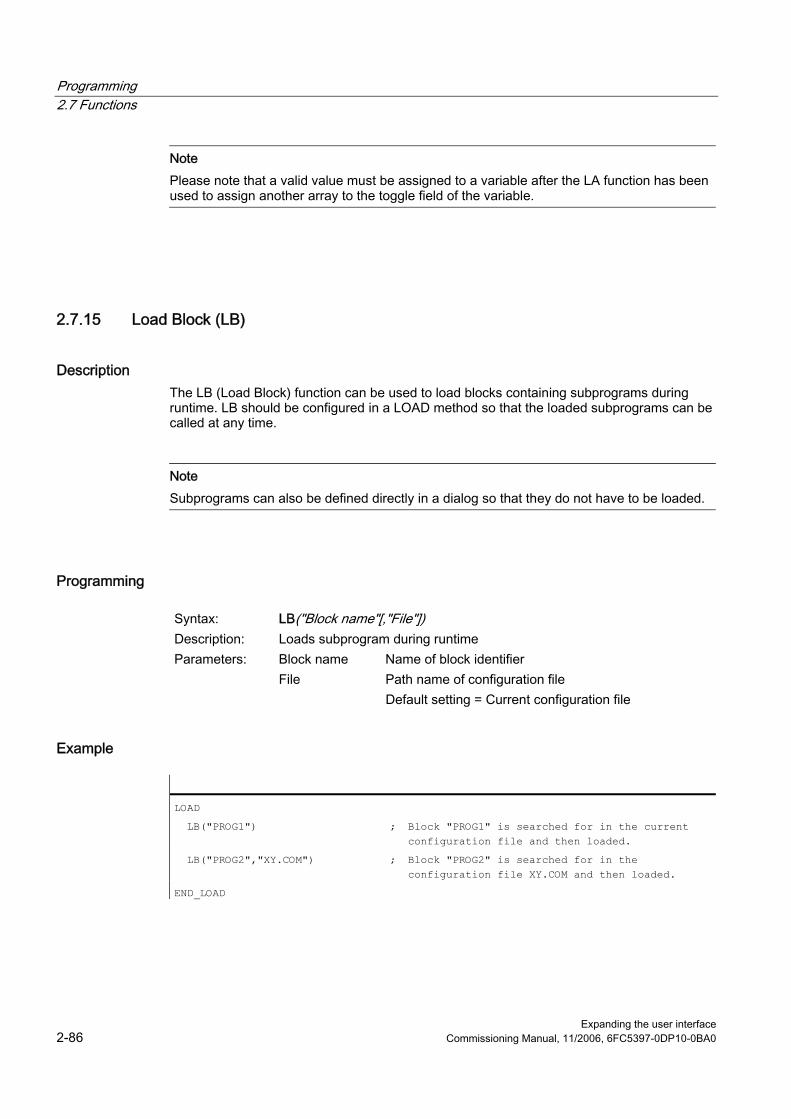
Programming 2.7 Functions
Expanding the user interface 2-86 Commissioning Manual, 11/2006, 6FC5397-0DP10-0BA0
Note Please note that a valid value must be assigned to a variable after the LA function has been used to assign another array to the toggle field of the variable.
2.7.15 Load Block (LB)
Description The LB (Load Block) function can be used to load blocks containing subprograms during runtime. LB should be configured in a LOAD method so that the loaded subprograms can be called at any time.
Note Subprograms can also be defined directly in a dialog so that they do not have to be loaded.
Programming
Syntax: LB("Block name"[,"File"]) Description: Loads subprogram during runtime Parameters: Block name Name of block identifier File Path name of configuration file
Default setting = Current configuration file
Example
LOAD
LB("PROG1") ; Block "PROG1" is searched for in the current configuration file and then loaded.
LB("PROG2","XY.COM") ; Block "PROG2" is searched for in the configuration file XY.COM and then loaded.
END_LOAD

Programming 2.7 Functions
Expanding the user interface Commissioning Manual, 11/2006, 6FC5397-0DP10-0BA0 2-87
2.7.16 Load Mask (LM)
description. The LM function can be used to load a new dialog.
Master dialog/Sub-dialog A dialog, which calls another dialog, but is not ended itself, is referred to as a master dialog. A dialog that is called by a master dialog is referred to as a sub-dialog.
Programming
Syntax: LM("Identifier"[,"File"] [,MSx [, VARx] ] ) Description: Loads dialog Parameters: Identifier Name of the dialog to be loaded File Path name (HMI file system or NC file system) of the
configuration file, default setting: Current configuration file
MSx Mode of dialog change 0: (Default setting) The current dialog disappears; the new
dialog is loaded and displayed. EXIT will send you back to the standard application. You can use the MSx parameter to determine whether or not the current dialog should be terminated when changing dialogs. If the current dialog is retained, variables can be transferred to the new dialog. The advantage of the MSx parameter is that the dialogs do not always need to be reinitialized when they are changed; instead, the data and layout of the current dialog are retained and data transfer is made easier.
1: The current master dialog is interrupted when the LM function is initiated; the new sub-dialog is loaded and displayed. EXIT will end the sub-dialog and return to the point at which the master dialog was interrupted. In the master dialog, the UNLOAD block is not processed during the interruption.
VARx Requirement: MS1 List of variables, which can be transferred from the master dialog to the sub-dialog. Up to 20 variables, each separated by a comma, can be transferred.

Programming 2.7 Functions
Expanding the user interface 2-88 Commissioning Manual, 11/2006, 6FC5397-0DP10-0BA0
Note Parameter VARx transfers only the value of the variable in each case, i.e., variables can be read and written in the sub-dialog, but are not visible in it. Variables can be returned from the sub-dialog to the master dialog by means of the EXIT function.
Example
PRESS(HS1)
LM("SCREEN FORM2","CFI.COM",1, POSX, POSY, DIAMETER)
; Interrupt screen form1 and open screen form2: Variables POSX, POSY and DIAMETER are transferred in doing this.
DLGL("Screen form2 ended") ; On returning from screen form2, the following text appears in the dialog line of screen form 1: Screen form2 ended.
END_PRESS
2.7.17 Load Softkey (LS)
Description The LS function can be used to display another softkey menu.
Programming
Syntax: LS("Identifier"[, "File"][, Merge]) Description: Displays softkey menu Parameters: Identifier Name of softkey menu File Path (HMI file system or NC file system) to the
configuration file Default: Current configuration file
Merge 0: All existing softkeys are deleted; the newly configured
softkeys are entered. 1: (Default setting) Only the newly configured softkeys
overwrite the existing softkeys. The other softkeys (= standard softkeys from HMI or ShopMill/ShopTurn) remain, and retain their functionality and text.
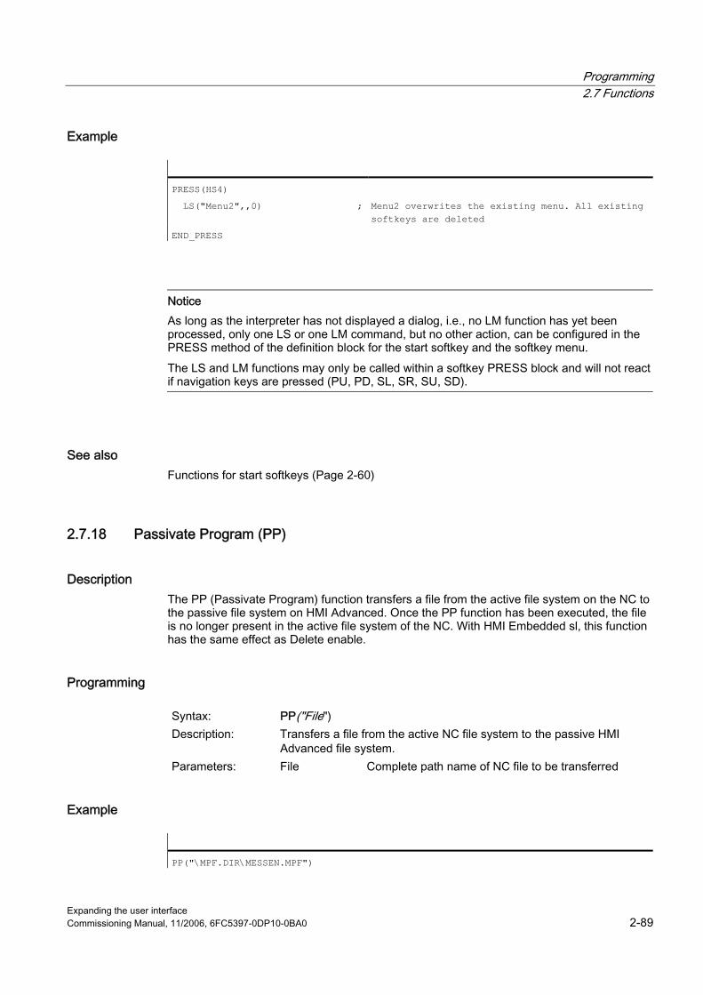
Programming 2.7 Functions
Expanding the user interface Commissioning Manual, 11/2006, 6FC5397-0DP10-0BA0 2-89
Example
PRESS(HS4)
LS("Menu2",,0) ; Menu2 overwrites the existing menu. All existing softkeys are deleted
END_PRESS
Notice As long as the interpreter has not displayed a dialog, i.e., no LM function has yet been processed, only one LS or one LM command, but no other action, can be configured in the PRESS method of the definition block for the start softkey and the softkey menu. The LS and LM functions may only be called within a softkey PRESS block and will not react if navigation keys are pressed (PU, PD, SL, SR, SU, SD).
See also Functions for start softkeys (Page 2-60)
2.7.18 Passivate Program (PP)
Description The PP (Passivate Program) function transfers a file from the active file system on the NC to the passive file system on HMI Advanced. Once the PP function has been executed, the file is no longer present in the active file system of the NC. With HMI Embedded sl, this function has the same effect as Delete enable.
Programming
Syntax: PP("File") Description: Transfers a file from the active NC file system to the passive HMI
Advanced file system. Parameters: File Complete path name of NC file to be transferred
Example
PP("\MPF.DIR\MESSEN.MPF")

Programming 2.7 Functions
Expanding the user interface 2-90 Commissioning Manual, 11/2006, 6FC5397-0DP10-0BA0
2.7.19 Read NC/PLC (RNP), Write NC/PLC (WNP)
Description The RNP (Read NC PLC) command can be used to read NC or PLC variables or machine data.
Programming
Syntax: RNP ("System or user variable", value) Description: Reads NC or PLC variable or machine data Parameters: System or user
variable Name of NC or PLC variable
Value Value that is to be written to the system or user variable. If the value is a String type, it must be written in double quotation marks.
Example
VAR2=RNP("$AA_IN[2]") ; Read NC variable
Description The WNP (Write NC PLC) command can be used to write NC or PLC variables or machine data. NC/PLC variables are accessed anew every time the WNP function is executed, i.e., NC/PLC access is always executed in a CHANGE method. It is advisable to use this option in cases where a system or user variable changes value frequently. If an NC/PLC variable is to be accessed only once, then it must be configured in a LOAD or UNLOAD method.
Programming
Syntax: WNP("System or user variable", value) Description: Writes NC or PLC variable or machine data Parameters: System or user
variable Name of NC or PLC variable
Value Value that is to be written to the system or user variable. If the value is a String type, it must be written in double quotation marks.
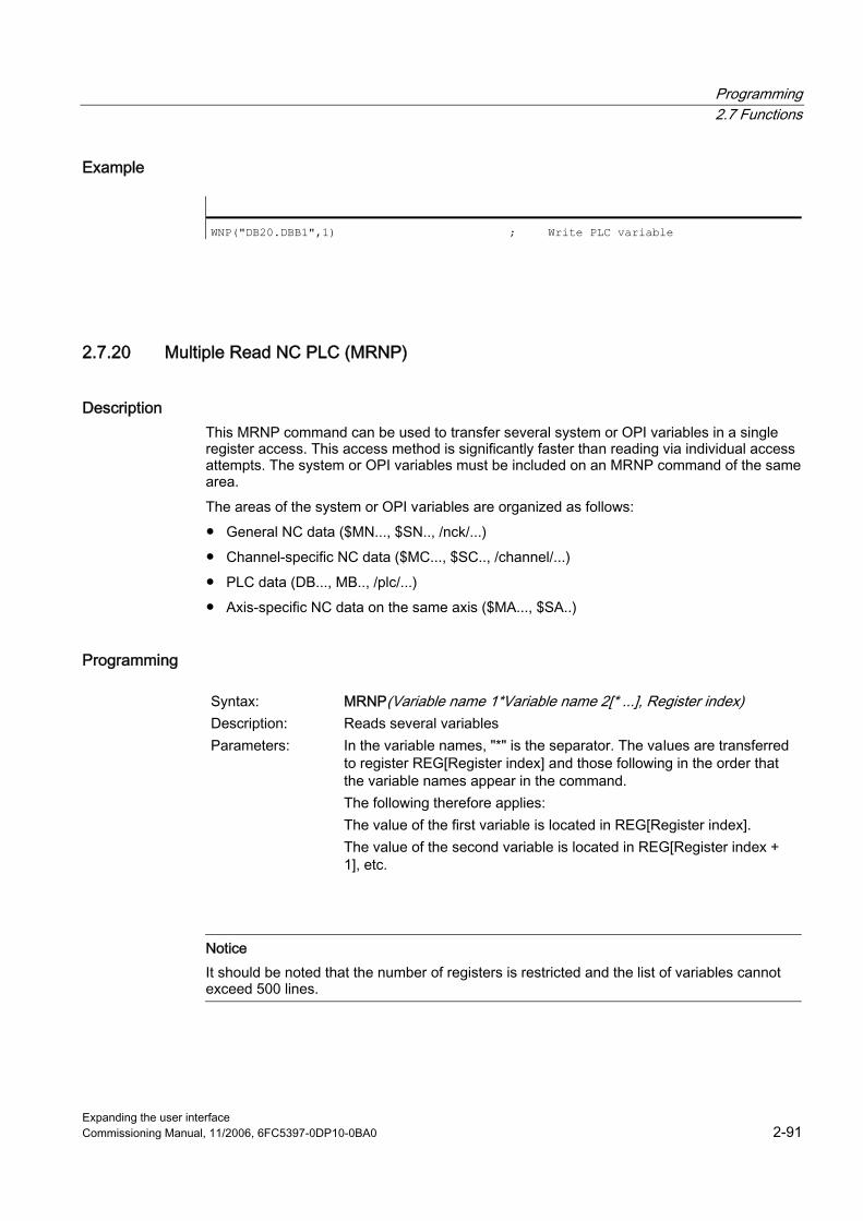
Programming 2.7 Functions
Expanding the user interface Commissioning Manual, 11/2006, 6FC5397-0DP10-0BA0 2-91
Example
WNP("DB20.DBB1",1) ; Write PLC variable
2.7.20 Multiple Read NC PLC (MRNP)
Description This MRNP command can be used to transfer several system or OPI variables in a single register access. This access method is significantly faster than reading via individual access attempts. The system or OPI variables must be included on an MRNP command of the same area. The areas of the system or OPI variables are organized as follows: ● General NC data ($MN..., $SN.., /nck/...) ● Channel-specific NC data ($MC..., $SC.., /channel/...) ● PLC data (DB..., MB.., /plc/...) ● Axis-specific NC data on the same axis ($MA..., $SA..)
Programming
Syntax: MRNP(Variable name 1*Variable name 2[* ...], Register index) Description: Reads several variables Parameters: In the variable names, "*" is the separator. The values are transferred
to register REG[Register index] and those following in the order that the variable names appear in the command. The following therefore applies: The value of the first variable is located in REG[Register index]. The value of the second variable is located in REG[Register index + 1], etc.
Notice It should be noted that the number of registers is restricted and the list of variables cannot exceed 500 lines.

Programming 2.7 Functions
Expanding the user interface 2-92 Commissioning Manual, 11/2006, 6FC5397-0DP10-0BA0
Example
MRNP("$R[0]*$R[1]*$R[2]*$R[3]",1) ; The values of variables $R[0] to $R[3] are written to REG[1] to REG[4].
Reading display machine data: Display machine data can be read with RNP ($MM...) within the LOAD block. General read/write access to display machine data is not possible using the "Expand user interface" function.
Note User variables may not have the same names as system or PLC variables.
NC variable All machine data, setting data and R parameters are available, but only certain system variables (see list in Appendix). In HMI Advanced, you can find the accessible system variables under operating area "Parameters"/"System variables"/"Edit view"/"Insert variable". All global and channel-specific user variables (GUDs) can be accessed. but local and program-global user variables cannot be processed.
Machine data Global machine data $MN_... Axis-specific machine data $MA_... Channel-specific machine data $MC_...
Setting data Global setting data $SN_... Axis-specific setting data $SA_... Channel-specific setting data $SC_...
System variables R parameter 1 $R[1]
PLC variable All PLC data are available.
PLC data Byte y bit z of data block x DBx.DBXy.z
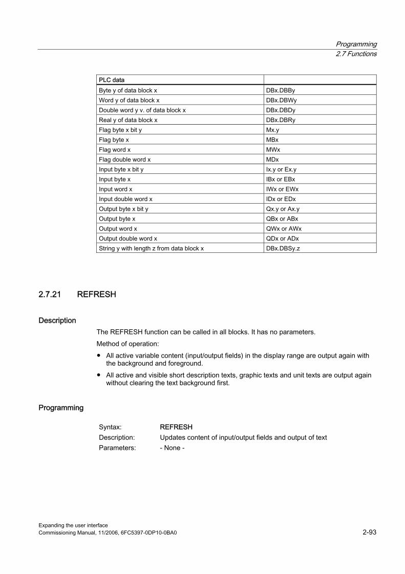
Programming 2.7 Functions
Expanding the user interface Commissioning Manual, 11/2006, 6FC5397-0DP10-0BA0 2-93
PLC data Byte y of data block x DBx.DBBy Word y of data block x DBx.DBWy Double word y v. of data block x DBx.DBDy Real y of data block x DBx.DBRy Flag byte x bit y Mx.y Flag byte x MBx Flag word x MWx Flag double word x MDx Input byte x bit y Ix.y or Ex.y Input byte x IBx or EBx Input word x IWx or EWx Input double word x IDx or EDx Output byte x bit y Qx.y or Ax.y Output byte x QBx or ABx Output word x QWx or AWx Output double word x QDx or ADx String y with length z from data block x DBx.DBSy.z
2.7.21 REFRESH
Description The REFRESH function can be called in all blocks. It has no parameters. Method of operation: ● All active variable content (input/output fields) in the display range are output again with
the background and foreground. ● All active and visible short description texts, graphic texts and unit texts are output again
without clearing the text background first.
Programming
Syntax: REFRESH Description: Updates content of input/output fields and output of text Parameters: - None -
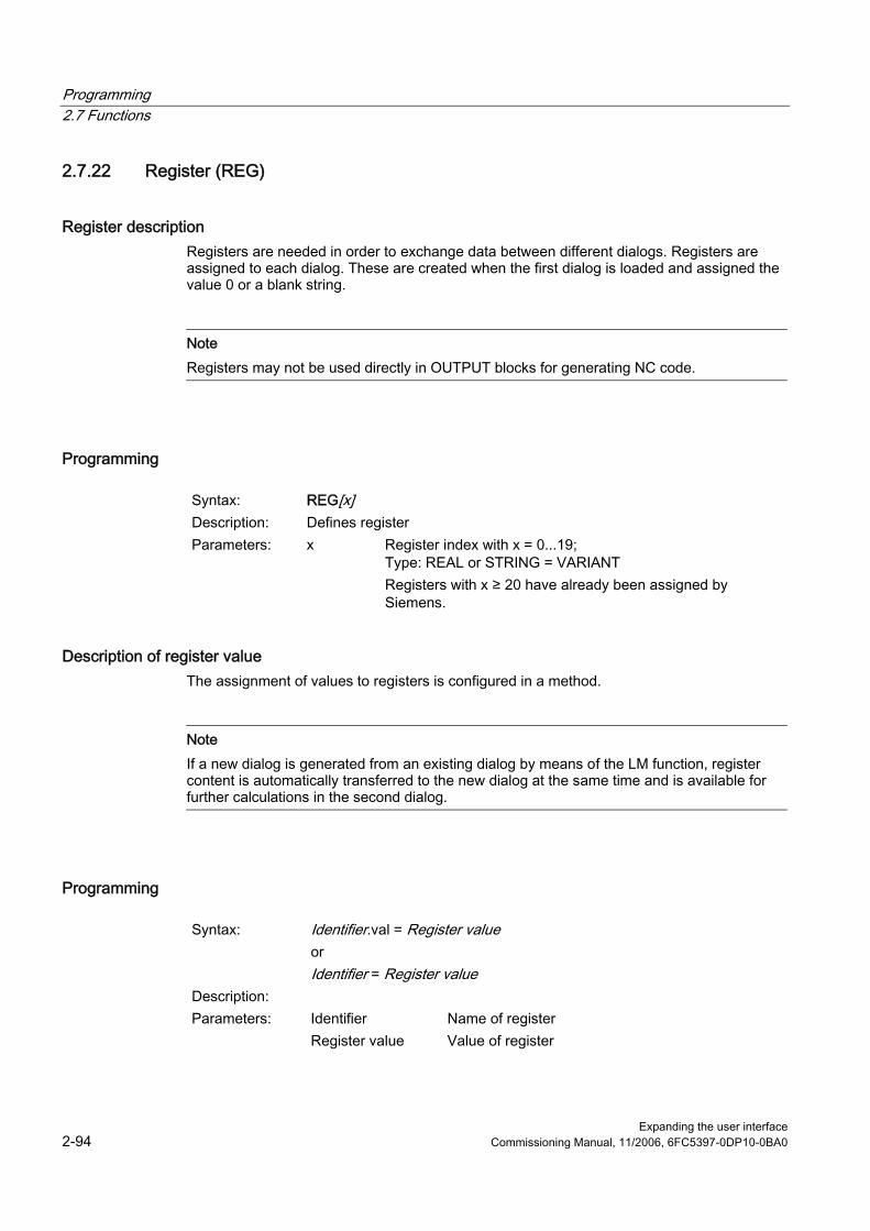
Programming 2.7 Functions
Expanding the user interface 2-94 Commissioning Manual, 11/2006, 6FC5397-0DP10-0BA0
2.7.22 Register (REG)
Register description Registers are needed in order to exchange data between different dialogs. Registers are assigned to each dialog. These are created when the first dialog is loaded and assigned the value 0 or a blank string.
Note Registers may not be used directly in OUTPUT blocks for generating NC code.
Programming
Syntax: REG[x] Description: Defines register Parameters: x Register index with x = 0...19;
Type: REAL or STRING = VARIANT Registers with x ≥ 20 have already been assigned by Siemens.
Description of register value The assignment of values to registers is configured in a method.
Note If a new dialog is generated from an existing dialog by means of the LM function, register content is automatically transferred to the new dialog at the same time and is available for further calculations in the second dialog.
Programming
Syntax: Identifier.val = Register value or Identifier = Register value
Description: Parameters: Identifier Name of register Register value Value of register
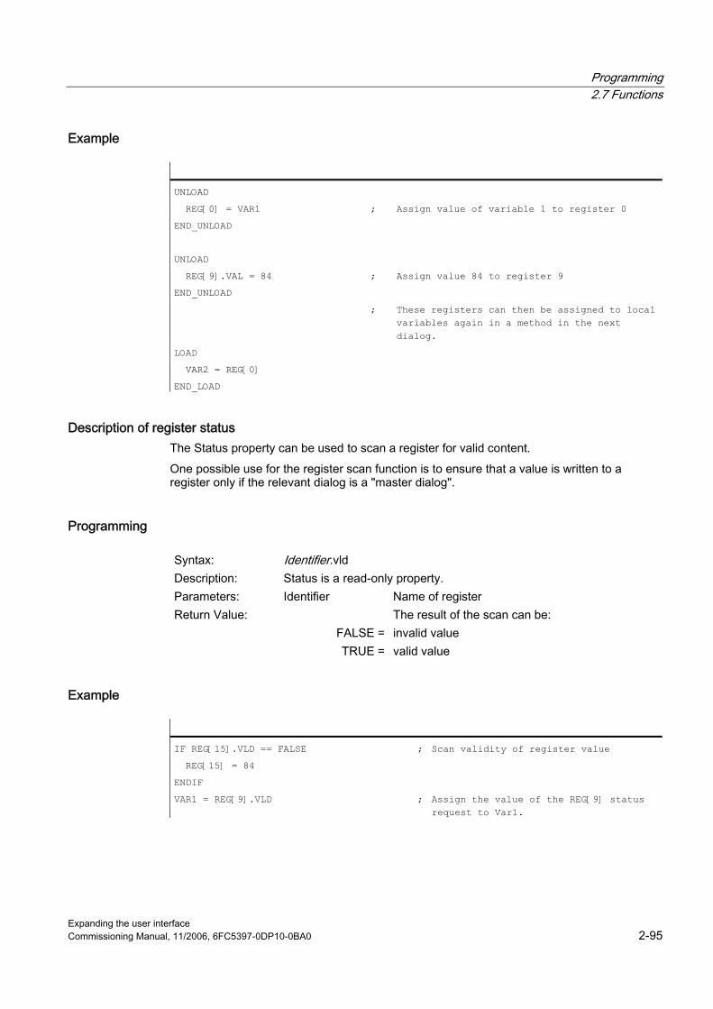
Programming 2.7 Functions
Expanding the user interface Commissioning Manual, 11/2006, 6FC5397-0DP10-0BA0 2-95
Example
UNLOAD
REG[0] = VAR1 ; Assign value of variable 1 to register 0
END_UNLOAD
UNLOAD
REG[9].VAL = 84 ; Assign value 84 to register 9
END_UNLOAD
; These registers can then be assigned to local variables again in a method in the next dialog.
LOAD
VAR2 = REG[0]
END_LOAD
Description of register status The Status property can be used to scan a register for valid content. One possible use for the register scan function is to ensure that a value is written to a register only if the relevant dialog is a "master dialog".
Programming
Syntax: Identifier.vld Description: Status is a read-only property. Parameters: Identifier Name of register Return Value: The result of the scan can be: FALSE = invalid value TRUE = valid value
Example
IF REG[15].VLD == FALSE ; Scan validity of register value
REG[15] = 84
ENDIF
VAR1 = REG[9].VLD ; Assign the value of the REG[9] status request to Var1.
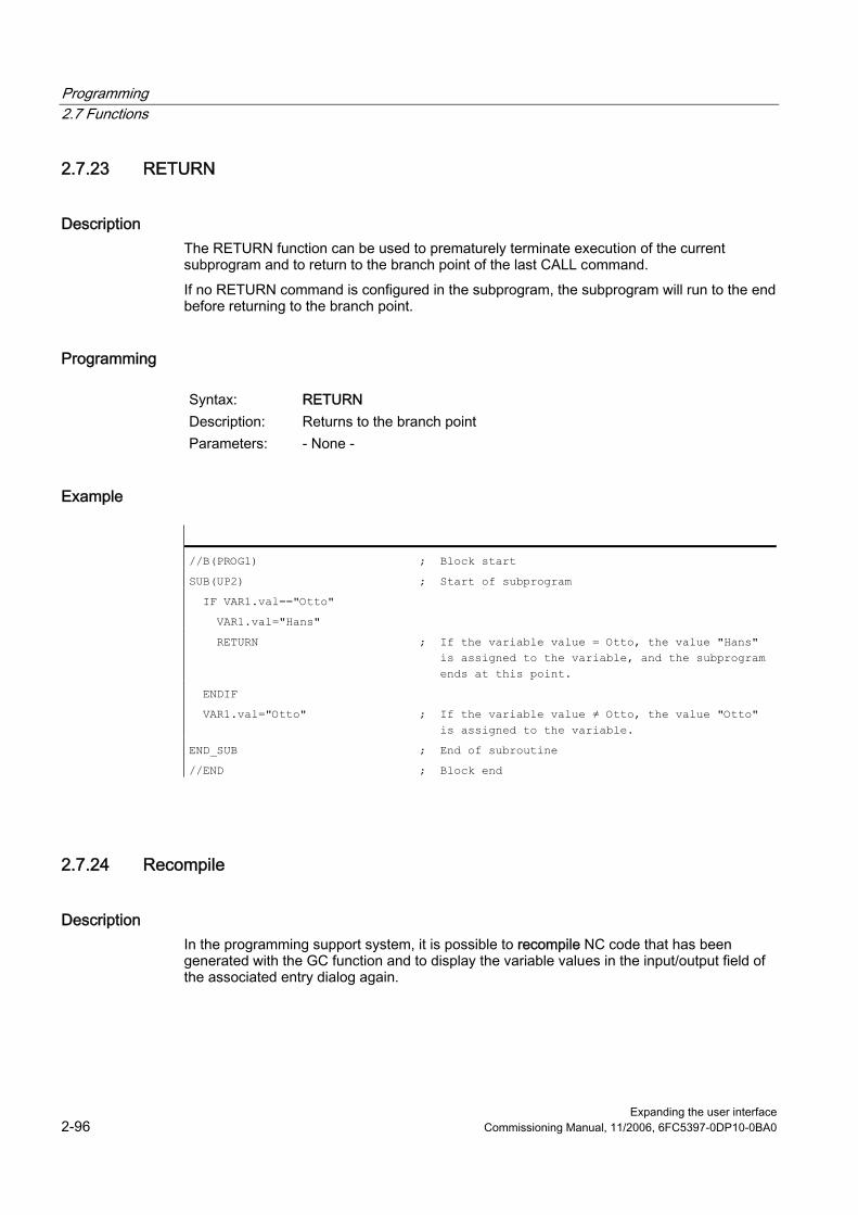
Programming 2.7 Functions
Expanding the user interface 2-96 Commissioning Manual, 11/2006, 6FC5397-0DP10-0BA0
2.7.23 RETURN
Description The RETURN function can be used to prematurely terminate execution of the current subprogram and to return to the branch point of the last CALL command. If no RETURN command is configured in the subprogram, the subprogram will run to the end before returning to the branch point.
Programming
Syntax: RETURN Description: Returns to the branch point Parameters: - None -
Example
//B(PROG1) ; Block start
SUB(UP2) ; Start of subprogram
IF VAR1.val=="Otto"
VAR1.val="Hans"
RETURN ; If the variable value = Otto, the value "Hans" is assigned to the variable, and the subprogram ends at this point.
ENDIF
VAR1.val="Otto" ; If the variable value ≠ Otto, the value "Otto" is assigned to the variable.
END_SUB ; End of subroutine
//END ; Block end
2.7.24 Recompile
Description In the programming support system, it is possible to recompile NC code that has been generated with the GC function and to display the variable values in the input/output field of the associated entry dialog again.
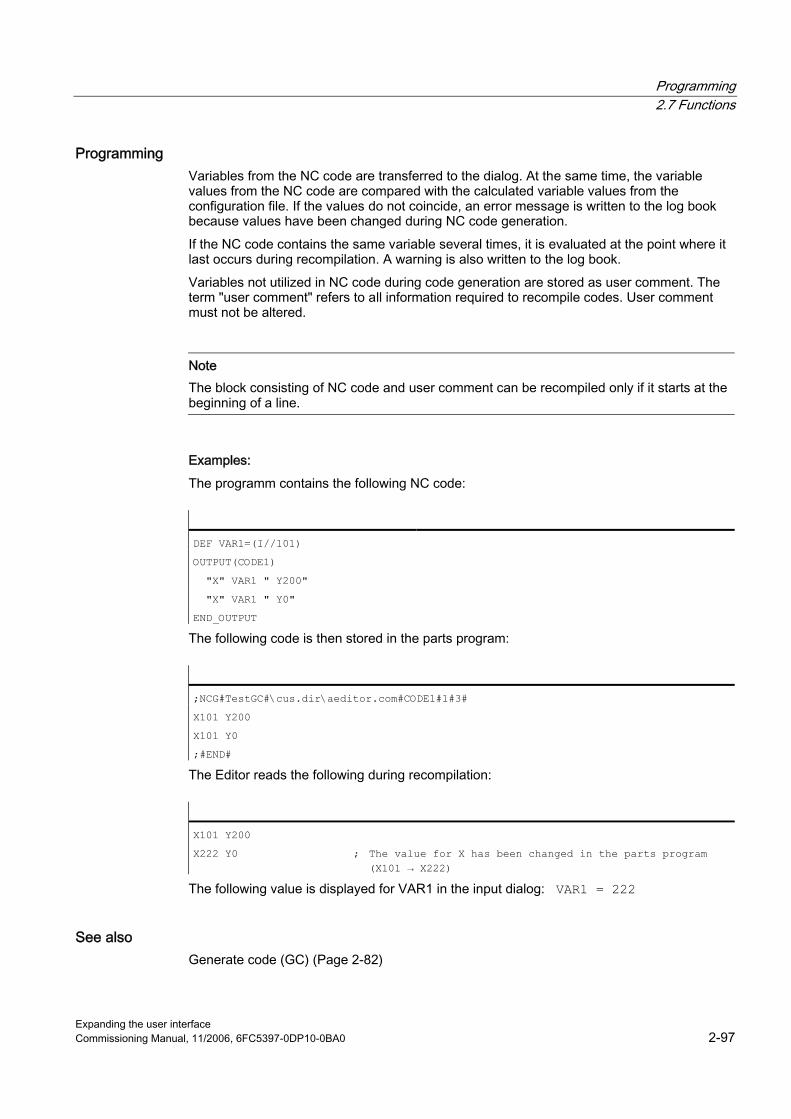
Programming 2.7 Functions
Expanding the user interface Commissioning Manual, 11/2006, 6FC5397-0DP10-0BA0 2-97
Programming Variables from the NC code are transferred to the dialog. At the same time, the variable values from the NC code are compared with the calculated variable values from the configuration file. If the values do not coincide, an error message is written to the log book because values have been changed during NC code generation. If the NC code contains the same variable several times, it is evaluated at the point where it last occurs during recompilation. A warning is also written to the log book. Variables not utilized in NC code during code generation are stored as user comment. The term "user comment" refers to all information required to recompile codes. User comment must not be altered.
Note The block consisting of NC code and user comment can be recompiled only if it starts at the beginning of a line.
Examples: The programm contains the following NC code:
DEF VAR1=(I//101)
OUTPUT(CODE1)
"X" VAR1 " Y200"
"X" VAR1 " Y0"
END_OUTPUT
The following code is then stored in the parts program:
;NCG#TestGC#\cus.dir\aeditor.com#CODE1#1#3#
X101 Y200
X101 Y0
;#END#
The Editor reads the following during recompilation:
X101 Y200
X222 Y0 ; The value for X has been changed in the parts program (X101 → X222)
The following value is displayed for VAR1 in the input dialog: VAR1 = 222
See also Generate code (GC) (Page 2-82)

Programming 2.7 Functions
Expanding the user interface 2-98 Commissioning Manual, 11/2006, 6FC5397-0DP10-0BA0
2.7.25 Search Forward, Search Backward (SF, SB)
Description The SF, SB (Search Forward, Search Backward) function is used to search for a string from the current cursor position in the NC program currently selected in the Editor and to output its value.
Programming
Syntax: SF("String") Identifiers: Search Forward: Search forward from the current cursor position Syntax: SB("String") Identifiers: Search Backward: Search backward from the current cursor position Parameters: String Text to be found
Rules governing text search ● A blank must be inserted before and after the search concept unit, consisting of search
string and its value, in the currently selected NC program. ● The system does not search for concepts within comment text or other strings. ● The value to be output must be a numerical expression. Expressions in the form of
"X1=4+5" are not recognized. ● The system recognizes hexadecimal constants in the form of X1='HFFFF', binary
constants in the form of X1='B10010' and exponential components in the form of X1='-.5EX-4'.
● The value of a string can be output if it contains the following between string and value: – Nothing – Blanks – Equality sign
Example The following notations are possible:
X100 Y200
Abc = SB("Y")
; The variable Abc is assigned the value 200
X100 Y 200
Abc = SB("Y")
; The variable Abc is assigned the value 200
X100 Y=200
Abc = SB("Y")
; The variable Abc is assigned the value 200
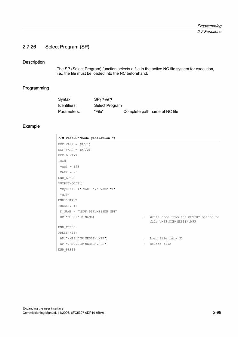
Programming 2.7 Functions
Expanding the user interface Commissioning Manual, 11/2006, 6FC5397-0DP10-0BA0 2-99
2.7.26 Select Program (SP)
Description The SP (Select Program) function selects a file in the active NC file system for execution, i.e., the file must be loaded into the NC beforehand.
Programming
Syntax: SP("File") Identifiers: Select Program Parameters: "File" Complete path name of NC file
Example
//M(TestGC/"Code generation:")
DEF VAR1 = (R//1)
DEF VAR2 = (R//2)
DEF D_NAME
LOAD
VAR1 = 123
VAR2 = -6
END_LOAD
OUTPUT(CODE1)
"Cycle123(" VAR1 "," VAR2 ")"
"M30"
END_OUTPUT
PRESS(VS1)
D_NAME = "\MPF.DIR\MESSEN.MPF"
GC("CODE1",D_NAME) ; Write code from the OUTPUT method to file \MPF.DIR\MESSEN.MPF
END_PRESS
PRESS(HS8)
AP("\MPF.DIR\MESSEN.MPF") ; Load file into NC
SP("\MPF.DIR\MESSEN.MPF") ; Select file
END_PRESS

Programming 2.7 Functions
Expanding the user interface 2-100 Commissioning Manual, 11/2006, 6FC5397-0DP10-0BA0
2.7.27 STRING functions
Overview The following functions enable strings to be processed: ● Determine length of string ● Find a character in a string ● Extract substring from left ● Extract substring from right ● Extract substring from mid-string ● Replace substring
LEN function: Length of a string
Syntax: LEN(string | varname) Description: Determines the number of characters in a string Parameters: string Every valid string expression. NULL is output if
string is blank. varname Any valid declared variable name Only one of the two parameters is allowed.
Example
DEF VAR01
DEF VAR02
LOAD
VAR01="HALLO"
VAR02=LEN(VAR01) ; Result = 5
END_LOAD
INSTR function: Search for character in string
Syntax: INSTR(Start, String1, String2 [,Direction]) Description: Searches for characters Parameters: Start Starting position for searching from string1 into
string2. Enter 0 to start searching at the beginning of string2.
String1 Character that is being searched for.
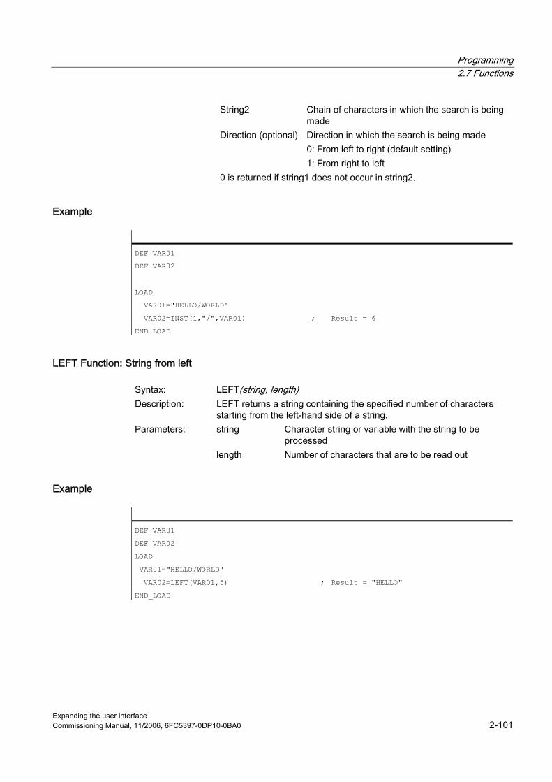
Programming 2.7 Functions
Expanding the user interface Commissioning Manual, 11/2006, 6FC5397-0DP10-0BA0 2-101
String2 Chain of characters in which the search is being made
Direction (optional) Direction in which the search is being made 0: From left to right (default setting) 1: From right to left
0 is returned if string1 does not occur in string2.
Example
DEF VAR01
DEF VAR02
LOAD
VAR01="HELLO/WORLD"
VAR02=INST(1,"/",VAR01) ; Result = 6
END_LOAD
LEFT Function: String from left
Syntax: LEFT(string, length) Description: LEFT returns a string containing the specified number of characters
starting from the left-hand side of a string. Parameters: string Character string or variable with the string to be
processed length Number of characters that are to be read out
Example
DEF VAR01
DEF VAR02
LOAD
VAR01="HELLO/WORLD"
VAR02=LEFT(VAR01,5) ; Result = "HELLO"
END_LOAD

Programming 2.7 Functions
Expanding the user interface 2-102 Commissioning Manual, 11/2006, 6FC5397-0DP10-0BA0
RIGHT function: String from right
Syntax: RIGHT(string, length) Description: RIGHT returns a string containing the specified number of characters
starting from the right-hand side of a string. Parameters: string Character string or variable with the string to be
processed length Number of characters that are to be read out
Example
DEF VAR01
DEF VAR02
LOAD
VAR01="HELLO/WORLD"
VAR02=LEFT(VAR01,4) ; Result = "WORLD"
END_LOAD
MIDS function: String from mid-string
Syntax: MIDS(string, start [, length]) Description: MIDS returns a string containing the specified number of characters
starting at the specified position in the string. Parameters: string Character string or variable with the string to be
processed start Start from where characters are to be read in the
string length Number of characters that are to be read out
Example
DEF VAR01
DEF VAR02
LOAD
VAR01="HELLO/WORLD"
VAR02=LEFT(VAR01,4,4) ; Result = "LO/W"
END_LOAD
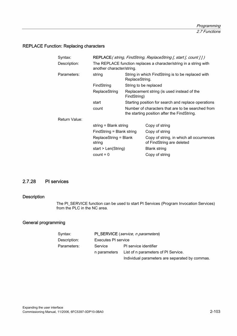
Programming 2.7 Functions
Expanding the user interface Commissioning Manual, 11/2006, 6FC5397-0DP10-0BA0 2-103
REPLACE Function: Replacing characters
Syntax: REPLACE( string, FindString, ReplaceString [, start [, count ] ] ) Description: The REPLACE function replaces a character/string in a string with
another character/string. Parameters: string String in which FindString is to be replaced with
ReplaceString. FindString String to be replaced ReplaceString Replacement string (is used instead of the
FindString) start Starting position for search and replace operations count Number of characters that are to be searched from
the starting position after the FindString. Return Value: string = Blank string Copy of string FindString = Blank string Copy of string ReplaceString = Blank
string Copy of string, in which all occurrences of FindString are deleted
start > Len(String) Blank string count = 0 Copy of string
2.7.28 PI services
Description The PI_SERVICE function can be used to start PI Services (Program Invocation Services) from the PLC in the NC area.
General programming
Syntax: PI_SERVICE (service, n parameters) Description: Executes PI service Parameters: Service PI service identifier n parameters List of n parameters of PI Service.
Individual parameters are separated by commas.

Programming 2.7 Functions
Expanding the user interface 2-104 Commissioning Manual, 11/2006, 6FC5397-0DP10-0BA0
Example
PRESS (HS2)
PI_SERVICE("_N_CREATO",55)
END_PRESS
PRESS(VS4)
PI_SERVICE("_N_CRCEDN",17,3)
END_PRESS
Starting OEM services The PI_START command executes a PI service based on OEM documentation.
Programming
Syntax: PI_START("Transfer string") Description: Executes PI service Parameters: "Transfer string" Unlike the OEM documentation, the transfer string
should be entered in inverted commas.
Example
PI_START("/NC,001,_N_LOGOUT")
Note Channel-dependent PI Services always refer to the current channel. PI services of the tool functions (TO area) always refer to the TO area that is assigned to the current channel.
See also List of Pl services (Page A-17)

Programming 2.7 Functions
Expanding the user interface Commissioning Manual, 11/2006, 6FC5397-0DP10-0BA0 2-105
2.7.29 External functions (only HMI Advanced)
Description Additional user-specific functions can be used by means of this call. External functions are stored in a DLL file and identified by an entry in the definition lines of the configuration file.
Note An external function must have at least one return parameter.
Programming
Syntax: FCTFunction name = ("File"/Type of return/Types of permanent call parameters/Types of variable call parameters)
Description: Declares additional, external functions Parameters: Function name Name of external function File Complete path to DLL file Type of return Data type of return value for function R, I, S, C, B. Data types of permanent call parameters and
return values. The data types are separated by commas.
Variable or register Data types of variable call parameters Syntax: FCTFunction name (call parameter) Call parameter List of all call parameters. Individual parameters
are separated by commas.
Example
//M(SCREEN FORM1)�
DEF VAR1 = (R)
DEF VAR2 = (I)
DEF RET = (I)
FCT InitConnection = ("c:\user\mydll.dll"/I/R,I,S/I,S)
; The external function "InitConnection" is declared. The data type of what has been declared. The data type of the return value is Integer, the data types of the permanent call parameters are Real, Integer and String; the data types of the variable call parameters are Integer and String.
LOAD
RET = InitConnection(VAR1+SIN(VAR3),13,"Servus",VAR2,

Programming 2.7 Functions
Expanding the user interface 2-106 Commissioning Manual, 11/2006, 6FC5397-0DP10-0BA0
//M(SCREEN FORM1)�
REG[2])
; The value of the "InitConnection" external function is assigned to RET along with the call parameters VAR1+SIN(VAR3), 13, Servus, VAR2 and REG[2].
END_LOAD
Extract from DLL file
void __export WINAPI InitConnection(ExtFctStructPtr FctRet, ExtFctStructPtr FctPar, char cNrFctPar)
FctRet->value.i Return value of function
FctPar[0]->value.r 1st parameter (VAR1+SIN(VAR3))
FctPar[1]->value.i 2nd parameter (13)
FctPar[2]->value.s 3rd parameter ("Servus")
FctPar[4]->value.i 4th parameter (reference to VAR2)
FctPar[5]->value.s 5th parameter (reference to REG[2])
cNrFctPar Number of parameters (5)

Programming 2.7 Functions
Expanding the user interface Commissioning Manual, 11/2006, 6FC5397-0DP10-0BA0 2-107
2.7.30 Programming example
Programming
//S(Start)
HS7=("Example", se1, ac7)
PRESS(HS7)
LM("Screen form4")
END_PRESS
//END
//M(Screen form4/"Example 4: Machine control panel"/"MST.BMP")
DEF byte=(I/0/0/"Input byte, default=0","Byte no.:",""/wr1,li1///380,40,100/480,40,50)
DEF feed=(IBB//0/"","Feed override.",""/wr1//"EB3"/20,180,100/130,180,100), Axistop=(B//0/"","Feed stop",""/wr1//"E2.2"/280,180,100/380,180,50/0,11)
DEF spin=(IBB//0/"","Spindle override",""/wr1//"EB0"/20,210,100/130,210,100), spinstop=(B//0/"","Spindle stop",""/wr1//"E2.4"/280,210,100/380,210,50/0,11)
DEF custom1=(IBB//0/"","User key 1",""/wr1//"EB6"/20,240,100/130,240,100)
DEF custom2=(IBB//0/"","User name 2",""/wr1//"EB7"/20,270,100/130,270,100)
DEF By1
DEF By2
DEF By3
DEF By6
DEF By7
HS1=("Input byte", SE1, AC4)
HS2=("")
HS3=("")
HS4=("")
HS5=("")
HS6=("")
HS7=("")
HS8=("")
VS1=("")
VS2=("")
VS3=("")
VS4=("")
VS5=("")
VS6=("")

Programming 2.7 Functions
Expanding the user interface 2-108 Commissioning Manual, 11/2006, 6FC5397-0DP10-0BA0
VS7=("")
VS8=("OK", SE1, AC7)
LOAD
By1=1
By2=2
By3=3
By6=6
By7=7
END_LOAD
PRESS(HS1)
Byte.wr=2
END_PRESS
CHANGE(Byte)
By1=byte+1
By2=byte+2
By3=byte+3
By6=byte+6
By7=byte+7
Feed.VAR="EB"<<By3
Spin.VAR="EB"<<Byte
Custom1.VAR="EB"<<By6
Custom2.VAR="EB"<<By7
Axisstop.VAR="E"<<By2<<".2"
Spinstop.VAR="E"<<By2<<".4"
Byte.wr=1
END_CHANGE
CHANGE(Axis stop)
IF Axistop==0
Axistop.BC=9
ELSE
Axistop.BC=11
ENDIF
END_CHANGE
CHANGE(Spin stop)
IF Spinstop==0
Spinstop.BC=9
ELSE
Spinstop.BC=11
ENDIF
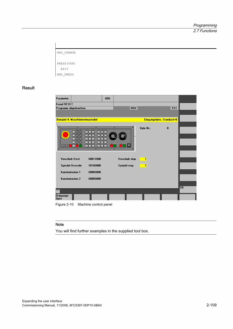
Programming 2.7 Functions
Expanding the user interface Commissioning Manual, 11/2006, 6FC5397-0DP10-0BA0 2-109
END_CHANGE
PRESS(VS8)
EXIT
END_PRESS
Result
Figure 2-10 Machine control panel
Note You will find further examples in the supplied tool box.

Programming 2.8 Operators
Expanding the user interface 2-110 Commissioning Manual, 11/2006, 6FC5397-0DP10-0BA0
2.8 2.8 Operators
Overview The following operators can be used when programming: ● Mathematical operators ● Relational operators ● Logic (Boolean) operators ● Bit operators ● Trigonometric functions
2.8.1 Mathematical operators
Overview
Mathematical operators Identifier + Addition - Subtraction * Multiplication / Division MOD Modulo operation ( ) Parentheses AND AND operator OR OR operator NOT NOT operator ROUND Round off numbers with decimal places
Example: VAR1.VAL = 45 * (4 + 3)
ROUND The ROUND operator is used to round off numbers with up to 12 decimal places during execution of a dialog configuration. The variable fields cannot accept the decimal places in the display.
Use ROUND is controlled by the user with two parameters: VAR1 = 5,2328543 VAR2 = ROUND( VAR1, 4 ) Result: VAR2 = 5,2339
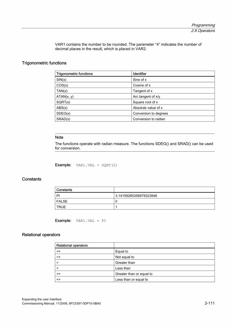
Programming 2.8 Operators
Expanding the user interface Commissioning Manual, 11/2006, 6FC5397-0DP10-0BA0 2-111
VAR1 contains the number to be rounded. The parameter “4” indicates the number of decimal places in the result, which is placed in VAR2.
Trigonometric functions
Trigonometric functions Identifier SIN(x) Sine of x COS(x) Cosine of x TAN(x) Tangent of x ATAN(x, y) Arc tangent of x/y SQRT(x) Square root of x ABS(x) Absolute value of x SDEG(x) Conversion to degrees SRAD(x) Conversion to radian
Note The functions operate with radian measure. The functions SDEG() and SRAD() can be used for conversion.
Example: VAR1.VAL = SQRT(2)
Constants
Constants PI 3.14159265358979323846 FALSE 0 TRUE 1
Example: VAR1.VAL = PI
Relational operators
Relational operators == Equal to <> Not equal to > Greater than < Less than >= Greater than or equal to <= Less than or equal to
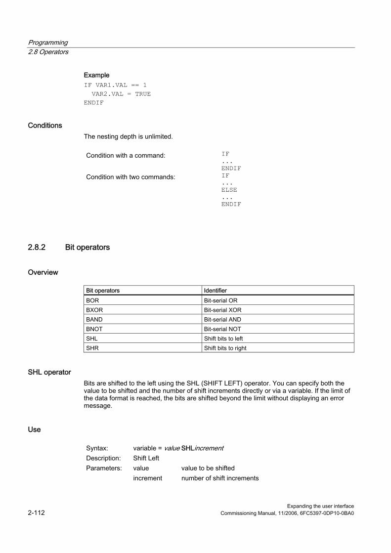
Programming 2.8 Operators
Expanding the user interface 2-112 Commissioning Manual, 11/2006, 6FC5397-0DP10-0BA0
Example IF VAR1.VAL == 1 VAR2.VAL = TRUE ENDIF
Conditions The nesting depth is unlimited.
Condition with a command: IF
... ENDIF
Condition with two commands: IF ... ELSE ... ENDIF
2.8.2 Bit operators
Overview
Bit operators Identifier BOR Bit-serial OR BXOR Bit-serial XOR BAND Bit-serial AND BNOT Bit-serial NOT SHL Shift bits to left SHR Shift bits to right
SHL operator Bits are shifted to the left using the SHL (SHIFT LEFT) operator. You can specify both the value to be shifted and the number of shift increments directly or via a variable. If the limit of the data format is reached, the bits are shifted beyond the limit without displaying an error message.
Use
Syntax: variable = value SHLincrement Description: Shift Left Parameters: value value to be shifted increment number of shift increments
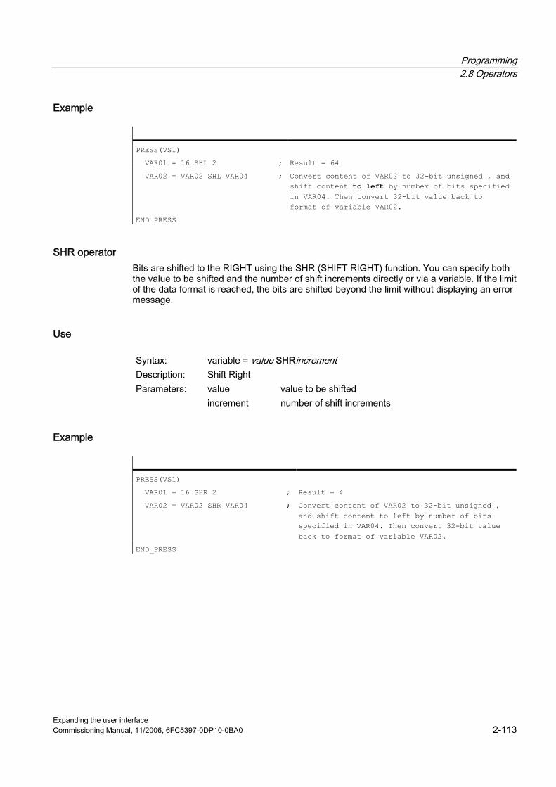
Programming 2.8 Operators
Expanding the user interface Commissioning Manual, 11/2006, 6FC5397-0DP10-0BA0 2-113
Example
PRESS(VS1)
VAR01 = 16 SHL 2 ; Result = 64
VAR02 = VAR02 SHL VAR04 ; Convert content of VAR02 to 32-bit unsigned�, and shift content to left by number of bits specified in VAR04. Then convert 32-bit value back to format of variable VAR02.
END_PRESS
SHR operator Bits are shifted to the RIGHT using the SHR (SHIFT RIGHT) function. You can specify both the value to be shifted and the number of shift increments directly or via a variable. If the limit of the data format is reached, the bits are shifted beyond the limit without displaying an error message.
Use
Syntax: variable = value SHRincrement Description: Shift Right Parameters: value value to be shifted increment number of shift increments
Example
PRESS(VS1)
VAR01 = 16 SHR 2 ; Result = 4
VAR02 = VAR02 SHR VAR04 ; Convert content of VAR02 to 32-bit unsigned�, and shift content to left by number of bits specified in VAR04. Then convert 32-bit value back to format of variable VAR02.
END_PRESS

Programming 2.8 Operators
Expanding the user interface 2-114 Commissioning Manual, 11/2006, 6FC5397-0DP10-0BA0
Expanding the user interface Commissioning Manual, 11/2006, 6FC5397-0DP10-0BA0 3-1
Programming support 33.1 3.1 What does programming support do?
Overview The purpose of the programming support system is to assist programmers in writing an NC program using the ASCII Editor. Customized user interfaces can also be created in the Programming support system. These interfaces are configured using the ASCII Editor and the tools provided by the "Expanding the Operator Interface" system. The system provides the following standard tools for this purpose: ● Cycle support ● Free contour programming ● Contour definition programming ● Recompile ● Simulation
Note For the sake of compatibility, the cycles support (//C...) function is still supported by the description language used in earlier versions and not by the syntax of the "Expanding the Operator Interface" system.
Creating new dialogs New operator interfaces are created with tools provided by the "Expanding the Operator Interface" system. However, there are some differences affecting programming support and these are described in this chapter.
Configuration file The definition of new dialogs for programming support is stored in configuration file AEDITOR.COM. ● Newly configured dialogs can be displayed in the Editor main screen through selection of
5 start softkeys (horizontal softkeys 2, 3, 4, 5 and 6). ● The default labels for softkeys 2 to 5 are "Contour", "Drilling", "Milling" and "Turning".
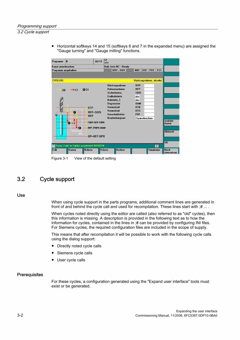
Programming support 3.2 Cycle support
Expanding the user interface 3-2 Commissioning Manual, 11/2006, 6FC5397-0DP10-0BA0
● Horizontal softkeys 14 and 15 (softkeys 6 and 7 in the expanded menu) are assigned the "Gauge turning" and "Gauge milling" functions.
Figure 3-1 View of the default setting
3.2 3.2 Cycle support
Use When using cycle support in the parts programs, additional comment lines are generated in front of and behind the cycle call and used for recompilation. These lines start with ;# ... . When cycles noted directly using the editor are called (also referred to as "old" cycles), then this information is missing. A description is provided in the following text as to how the information for cycles, contained in the lines in ;# can be provided by configuring INI files. For Siemens cycles, the required configuration files are included in the scope of supply. This means that after recompilation it will be possible to work with the following cycle calls using the dialog support: ● Directly noted cycle calls ● Siemens cycle calls ● User cycle calls
Prerequisites For these cycles, a configuration generated using the "Expand user interface" tools must exist or be generated.

Programming support 3.2 Cycle support
Expanding the user interface Commissioning Manual, 11/2006, 6FC5397-0DP10-0BA0 3-3
For dialogs generated with the "Expand user interface" function for the purpose of supporting user cycles, the information in the dialog descriptive files can be used for this process. Cycle-specific settings can be made in the configuration to define whether cycles with ;# lines are to be processed in the parts program or recompiled via the configuration files. This process can be used to optionally generate the addition of ;# lines required for dialog support in the parts program for directly noted “old" cycles.
Configuration The WIZARD.INI file can be stored in the following directories. The directories are browsed in this sequence: ..\user ..\oem ..\hmi_adv ..\mmc2 The following entries refer to cycle packages, e.g.: INI_1=bohren.ini INI_2=drehen.ini ... INI_n=paket.ini The information in the [MMC_CycleWizard] section is added so that it is up to date. Cycle-specific entries in the following format are located in the relevant PAKET.INI files:
[cycleName] ; Name of the cycle as a separate section Mname= ;
Obligatory dialog name
Dir= ; Obligatory
Directory of file with dialog information
Dname= ; Obligatory
File with dialog information
Output ; Obligatory
Name of the OUTPUT block
Anzp= ; Obligatory
Number of parameters (defined variables)
Version= ; Optional cycle version, without entry 0 Code_typ= ; Optional output with = 0 or without = 1 ;#
lines Example: [CYCLE83] Mname=CYC83 Dir=cst.dir Output=bohren.ini Anzp=17 Version=3 Code_typ=0
Programming support 3.3 Activating a dialog from the NC program
Expanding the user interface 3-4 Commissioning Manual, 11/2006, 6FC5397-0DP10-0BA0
Different cycle versions A differentiation is made between various versions of cycles with the same name using the version number. Main block/secondary block and block numbers in front of the cycle call are kept unchanged. Cycle call line in the parts program: /1234 :44 CYCLE94(, , ) After expansion by the string and ;# lines: ;NCG#CYC94#\CST.DIR\DREHEN.COM#NC1#1#*NCG;*RO*;*HD* ;##########*NCG;*RO*;*HD* /1234 :44 CYCLE94(,,"",) ;#END#*NCG;*RO*;*HD*
See also Recompile (Page 2-96) Search Forward, Search Backward (SF, SB) (Page 2-98)
3.3 3.3 Activating a dialog from the NC program
Introduction With HMI Advanced and HMI Embedded sl, dialogs defined by the user can be displayed. The appearance of the dialogs is defined through configuration (modification of COM file in the cycles directory). The dialog is called and exited by function calls from the parts program. User-configured dialog screens do not modify the HMI system software (user interface). User-defined dialogs cannot be called simultaneously in different channels.
Command channel The "Activate dialog from NC Program" function is also referred to as a "command channel".
Activating the command channel One possible application of user-defined dialogs is, for example, to assign defined values to particular user variables (GUD) prior to a parts program run. ● Up to 2 channels:
The "command channel" is activated by default for channels 1 and 2. ● More than 2 channels:
For HMI Advanced, the "command channel" must be activated (if the Siemens measuring cycles have not yet been installed). This requires a modification to be made to the file F:\MMC2\ COMIC.NSK in the "Startup" operating area:

Programming support 3.3 Activating a dialog from the NC program
Expanding the user interface Commissioning Manual, 11/2006, 6FC5397-0DP10-0BA0 3-5
Select file F:\MMC2\COMIC.NSK in the "Startup" operating area using the softkeys "HMI" → "Editor" and attach the following text (after channels 1 and 2): REM CHANNEL TOPIC(machineswitch) COMIC_START(COMIC001MachineSwitch"...) [compare the text for channels 1 and 2] When the control is restarted (OFF/ON), the command channel is activated for the corresponding channel.
Activation with HMI Advanced Content of the COMIC.NSK file: REM ----- TYPICAL COMIC START REM CHANNEL 1 TOPIC(machineswitch) COMIC_START("COMIC001MachineSwitch ",/Channel/Configuration/mmcCmd[u1], /Channel/Configuration/mmcCmdQuit[u1]) REM CHANNEL 2 TOPIC(machineswitch) COMIC_START("COMIC002MachineSwitch ",/Channel/Configuration/mmcCmd[u2], /Channel/Configuration/mmcCmdQuit[u2])
3.3.1 Structure of "MMC" instruction
Programming
Syntax: MMC ("Operating area, command, Com file, dialog box name, user-data definition file, graphics file, display time or acknowledgment variable, text variables...", "Acknowledgment mode")
Parameters: Operating area Name of softkey used to call the configured user dialogs. Default: CYCLES displayed as "Cycles" on softkey 14 and accessible via the <ETC> key.
Command PICTURE_ON PICTURE_OFF FF
Select screen Deselect screen
COM file Name of the dialog screen file (max. 8 characters, in the user, manufacturer, or standard cycles directory). The dialog display appearance is defined here. The dialog screen is used to display user variables and/or comment texts.
Dialog name The individual dialogs are selected via the dialog names.
Programming support 3.3 Activating a dialog from the NC program
Expanding the user interface 3-6 Commissioning Manual, 11/2006, 6FC5397-0DP10-0BA0
GUD file User-data definition file accessed on reading/writing of variables.
Graphics file (HMI Advanced only)
File name of the BMP graphic to be inserted
Acknowledgment variable (HMI Advanced only) or display time
Acknowledgment variable Display time
in acknowledgment mode "A" in acknowledgment mode "N"
Text variable Screen header or comment text from a text variable in the COM file.
Acknowledgment mode
"S" for Synchronous "A" for Asynchronous "N" for No Quit
Acknowledgment via "OK" softkey Acknowledgment via configured softkeys No acknowledgment, but display time
Storage structure of graphics *.bmp files are stored in resolution-specific subdirectories: ● For standard cycles:
\CST.DIR\HLP.DIR\640.DIR For 640 dpi resolution \CST.DIR\HLP.DIR\800.DIR For 800 dpi resolution \CST.DIR\HLP.DIR\1024.DIR For 1024 dpi resolution
● For user cycles:
\CUS.DIR\HLP.DIR\640.DIR For 640 dpi resolution \CUS.DIR\HLP.DIR\800.DIR For 800 dpi resolution \CUS.DIR\HLP.DIR\1024.DIR For 1024 dpi resolution
● For manufacturer cycles:
\CMA.DIR\HLP.DIR\640.DIR For 640 dpi resolution \CMA.DIR\HLP.DIR\800.DIR For 800 dpi resolution \CMA.DIR\HLP.DIR\1024.DIR For 1024 dpi resolution

Programming support 3.3 Activating a dialog from the NC program
Expanding the user interface Commissioning Manual, 11/2006, 6FC5397-0DP10-0BA0 3-7
3.3.2 Example of MMC instruction
MMC instruction in the parts program MMC("CYCLES,PICTURE_ON,T_SK.COM,PICTURE1,MGUD.DEF,PICTURE3.BMP, TEST_1,A1","S")
CYCLES Operating area PICTURE_ON Select dialog T_SK.COM File name in cycle directory PICTURE1 Name of the dialog MGUD.DEF User data definition file PICTURE3.BMP Name of graphics file (HMI Advanced only) TEST_1 Acknowledgment variable (HMI Advanced only)
or display time in "N" mode A1 Screen header or comment from a text variable (COM file) S Acknowledgment mode: Synchronized
User variables in definition directory %_N_UGUD_DEF ;$PATH=/_N_DEF_DIR DEF CHAN REAL TEST_1
CHAN Applicable channel REAL Data type TEST_1 Name of user variable
Dialog screen file in the cycles directory (*.COM) //C3(Screen2) R/ 15 75 / 5 /COMMENT, %1 %2 %3/ W,RJ / TEST_1 / ...
R Variable Type: Real, Integer or String 15 75 Permissible range: 15 to 75 5 Default setting for user variable COMMENT, %1 %2 %3 Comment text with optional text variables W,RJ Access
type: W = Read and write R = Read-only W, RJ = Read and write with comment J = Right-justified in relation to input/output field <without> = Left-justified in relation to input/output field
TEST_1 User variable

Programming support 3.3 Activating a dialog from the NC program
Expanding the user interface 3-8 Commissioning Manual, 11/2006, 6FC5397-0DP10-0BA0
Text variable [Text variables] A1 = Example 2: MMC instruction without acknowledgment
A1 Reference parameters for MMC
instruction Example 2: MMC statement without acknowledgment Screen header or comment text
Note For variable names, text variables and cycle names, capital letters must be used.
Configuring softkeys for dialog call Softkey assignment for MMC command with asynchronous acknowledgment mode. [PICTURE3] SK1 = END SK2 = Screen2 Softkeys SK0 to SK15 can be configured

Programming support 3.3 Activating a dialog from the NC program
Expanding the user interface Commissioning Manual, 11/2006, 6FC5397-0DP10-0BA0 3-9
3.3.3 Example 1: MMC instruction without acknowledgment
Selecting N10 MMC("CYCLES,PICTURE_ON,T_SK.COM,PICTURE1,GUD4.DEF,,,A1","N") N20 TEST_1 = 1 N25 G4 F10 N30 MMC("CYCLES,PICTURE_OFF","N") M30 Parameters:
Dialog file (*.COM) //C1(PICTURE1)
(R///USER VAR TEST_1/W/TEST_1///) Text variable
[TEXT VARIABLES] A1 =........Example 1: MMC command without acknowledgment
Figure 3-2 Example 1 Without acknowledgment
Sequence of operations The user variable TEST_1 from GUD4.DEF with header A1 is displayed for a short time. The hold time comes from parts program block N25.

Programming support 3.3 Activating a dialog from the NC program
Expanding the user interface 3-10 Commissioning Manual, 11/2006, 6FC5397-0DP10-0BA0
3.3.4 Example 2: Hold time and optional text variables
Selecting N10 MMC("CYCLES,PICTURE_ON,T_SK.COM,PICTURE6,GUD4.DEF,,10,T1,G1","N") N15 G4 F15 N30 MMC("CYCLES,PICTURE_OFF","N") M30 Parameters:
Dialog file (*.COM) //C6(screen6)
(R///USER VAR TEST_1,%1/W/TEST_1///) Text variable
[TEXT VARIABLES] T1 = Example 2: Dwell time and optional text variables ... G1 = Optional text variable
The 7th parameter is interpreted as the display time for the mode without acknowledgment (10 seconds). The contents of the table are then deleted. The dialog remains on the screen until PICTURE_OFF is selected. The 8th parameter (T1) is the text variable for the header. If there is no entry, the operating area name, "cycles", is displayed. The parameters 9 to 23 are optional text variables ("G1=optional text variable"). In this COM file, the optional text variables must be preassigned in the [Text variables] section.
Figure 3-3 Example 2 Dwell time
Sequence of operations The comment text from the COM file (USER VAR TEST_1) is expanded in this example at the position of the first wild card (%1) to include the contents of the text variable
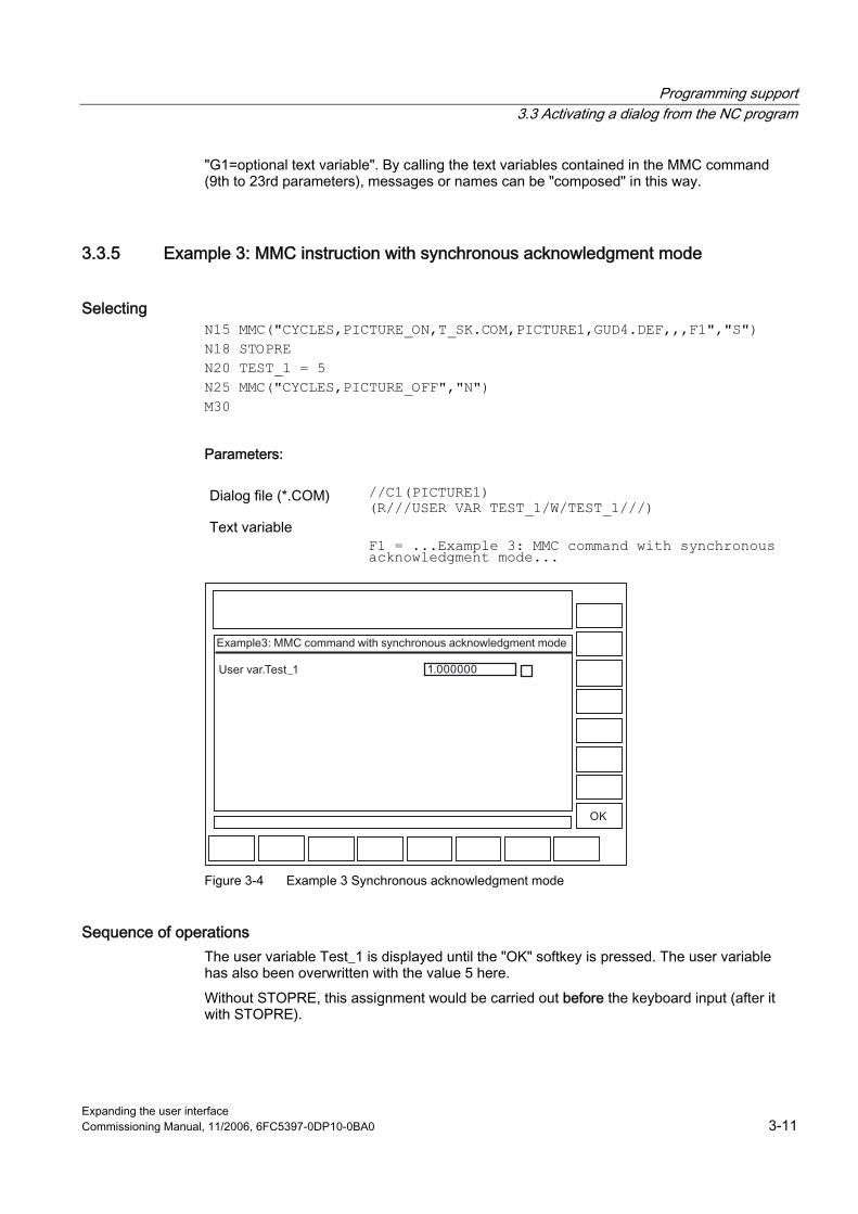
Programming support 3.3 Activating a dialog from the NC program
Expanding the user interface Commissioning Manual, 11/2006, 6FC5397-0DP10-0BA0 3-11
"G1=optional text variable". By calling the text variables contained in the MMC command (9th to 23rd parameters), messages or names can be "composed" in this way.
3.3.5 Example 3: MMC instruction with synchronous acknowledgment mode
Selecting N15 MMC("CYCLES,PICTURE_ON,T_SK.COM,PICTURE1,GUD4.DEF,,,F1","S") N18 STOPRE N20 TEST_1 = 5 N25 MMC("CYCLES,PICTURE_OFF","N") M30 Parameters:
Dialog file (*.COM) //C1(PICTURE1)
(R///USER VAR TEST_1/W/TEST_1///) Text variable
F1 = ...Example 3: MMC command with synchronous acknowledgment mode...
Figure 3-4 Example 3 Synchronous acknowledgment mode
Sequence of operations The user variable Test_1 is displayed until the "OK" softkey is pressed. The user variable has also been overwritten with the value 5 here. Without STOPRE, this assignment would be carried out before the keyboard input (after it with STOPRE).
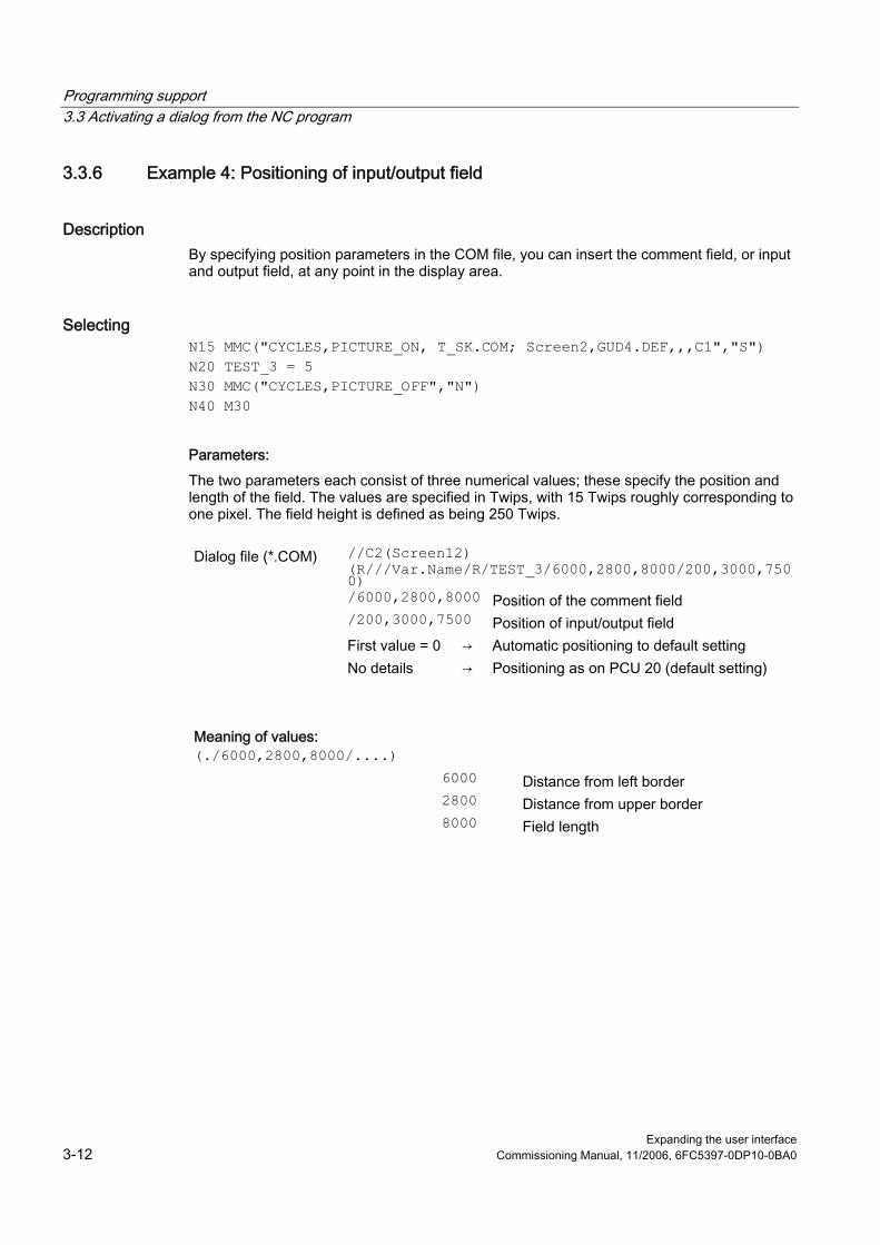
Programming support 3.3 Activating a dialog from the NC program
Expanding the user interface 3-12 Commissioning Manual, 11/2006, 6FC5397-0DP10-0BA0
3.3.6 Example 4: Positioning of input/output field
Description By specifying position parameters in the COM file, you can insert the comment field, or input and output field, at any point in the display area.
Selecting N15 MMC("CYCLES,PICTURE_ON, T_SK.COM; Screen2,GUD4.DEF,,,C1","S") N20 TEST_3 = 5 N30 MMC("CYCLES,PICTURE_OFF","N") N40 M30 Parameters: The two parameters each consist of three numerical values; these specify the position and length of the field. The values are specified in Twips, with 15 Twips roughly corresponding to one pixel. The field height is defined as being 250 Twips.
Dialog file (*.COM) //C2(Screen12)
(R///Var.Name/R/TEST_3/6000,2800,8000/200,3000,7500)
/6000,2800,8000 Position of the comment field /200,3000,7500 Position of input/output field First value = 0 → Automatic positioning to default setting No details → Positioning as on PCU 20 (default setting)
Meaning of values: (./6000,2800,8000/....) 6000 Distance from left border 2800 Distance from upper border 8000 Field length

Programming support 3.3 Activating a dialog from the NC program
Expanding the user interface Commissioning Manual, 11/2006, 6FC5397-0DP10-0BA0 3-13
Sequence of operations It is possible to graphically configure 16 comment and 16 input or output fields. Where there are more than 16 fields, they can be controlled via a scroll bar.
Figure 3-5 Example 4a Position parameters
To ensure that the cursor control works seamlessly, the configured fields must overlap:
Figure 3-6 Example 4b Position parameters
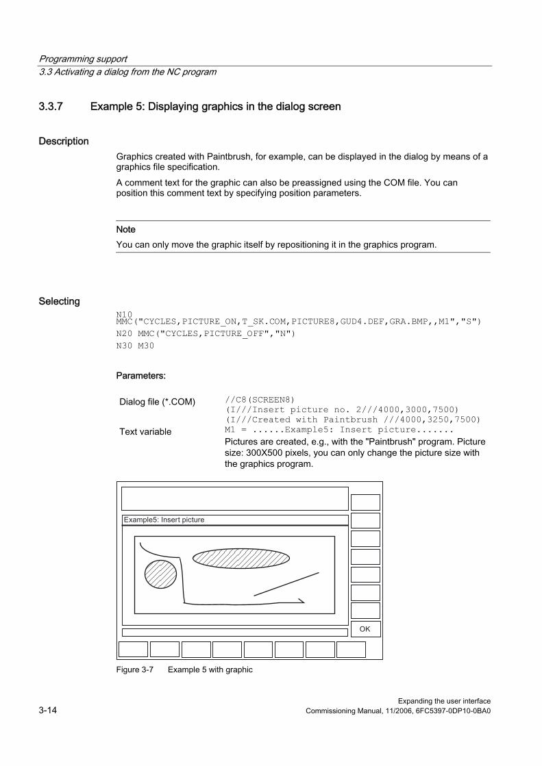
Programming support 3.3 Activating a dialog from the NC program
Expanding the user interface 3-14 Commissioning Manual, 11/2006, 6FC5397-0DP10-0BA0
3.3.7 Example 5: Displaying graphics in the dialog screen
Description Graphics created with Paintbrush, for example, can be displayed in the dialog by means of a graphics file specification. A comment text for the graphic can also be preassigned using the COM file. You can position this comment text by specifying position parameters.
Note You can only move the graphic itself by repositioning it in the graphics program.
Selecting N10 MMC("CYCLES,PICTURE_ON,T_SK.COM,PICTURE8,GUD4.DEF,GRA.BMP,,M1","S") N20 MMC("CYCLES,PICTURE_OFF","N") N30 M30 Parameters:
Dialog file (*.COM) //C8(SCREEN8)
(I///Insert picture no. 2///4000,3000,7500) (I///Created with Paintbrush ///4000,3250,7500)
Text variable M1 = ......Example5: Insert picture....... Pictures are created, e.g., with the "Paintbrush" program. Picture size: 300X500 pixels, you can only change the picture size with the graphics program.
Figure 3-7 Example 5 with graphic

Programming support 3.3 Activating a dialog from the NC program
Expanding the user interface Commissioning Manual, 11/2006, 6FC5397-0DP10-0BA0 3-15
3.3.8 Example 6: Displaying OPI variables
Description You can display OPI variables.
Selecting MMC("CYCLES,PICTURE_ON,T_SK.COM,SCREEN7,GUD4.DEF,,TEST_1,J1","S") Parameters:
Dialog file (*.COM) //C7(Screen7)
(R///Test_1/R/Test_1) (I///); (Interpreted as space line)) (R///Actual value from axis 1/R/$actual value) (R//1/R parameter 12/W/$R[12])
Text variable J1 = ...Example7: OPI variables [OPIVar] $Actual value=/Channel/machineaxis/actToolbasePos[u1,1] $R[12]=/Channel/Parameter/rpa[u1,12]
Figure 3-8 Example 6 with OPI variable
Sequence of operations A space line is created under the variable TEST_1. The actual axis value is read-only. R12 is preset with 1.

Programming support 3.3 Activating a dialog from the NC program
Expanding the user interface 3-16 Commissioning Manual, 11/2006, 6FC5397-0DP10-0BA0
3.3.9 Example 7: Asynchronous acknowledgment mode with softkeys
Description Softkeys can be preprogrammed in the COM file for display in asynchronous mode, linked with the acknowledgment variable and evaluated in the parts program.
Selecting N10 QUIT_1 = "START" N20 MMC("CYCLES,PICTURE_ON,T_SK.COM,PICTURE3,GUD4.DEF,"QUIT_1,K1","A") N30 LABEL0: N40 STOPRE N50 IF MATCH (QUIT_1,"SK1") >= 0 GOTOF LABEL1 N60 IF MATCH (QUIT_1,"SK2") >= 0 GOTOF LABEL2 N70 GOTOB LABEL0 N80 LABEL2: N90 MMC("CYCLES,PICTURE_ON,T_SK.COM,PICTURE1,GUD4.DEF,"N1","N") N100 G4F10 N110 LABEL1: N120 MMC("CYCLES,PICTURE_OFF","N") N130 M30 Parameters:
Dialog file (*.COM) //C3(Screen3)
(S///USER VAR QUIT_1/W/QUIT_1//) Text variable
[TEXT VARIABLES] K1 = ..Example8: MMC command with asynchronous acknowledgment mode N1 = ..Example8: Picture2
Softkey [SCREEN3] SK1 = END SK2 = Screen2
Program structure The acknowledgment variable is defined as a string. Length of the string: >= 20 ;(Values < 20 are evaluated internally only,� SK0 ... SK15 are entered at position 17...20 when a softkey is actuated). The string is assigned a value in the parts program and any old softkey information is deleted. Before the parts program can branch as a function of the acknowledgment variable, the block search must be halted by the STOPRE command.
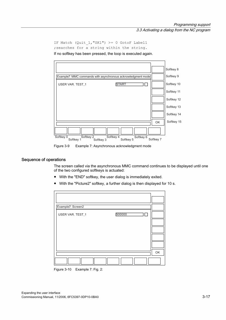
Programming support 3.3 Activating a dialog from the NC program
Expanding the user interface Commissioning Manual, 11/2006, 6FC5397-0DP10-0BA0 3-17
IF Match (Quit_1,"SK1") >= 0 GotoF Label1 ;searches for a string within the string. If no softkey has been pressed, the loop is executed again.
Figure 3-9 Example 7: Asynchronous acknowledgment mode
Sequence of operations The screen called via the asynchronous MMC command continues to be displayed until one of the two configured softkeys is actuated: ● With the "END" softkey, the user dialog is immediately exited. ● With the "Picture2" softkey, a further dialog is then displayed for 10 s.
Figure 3-10 Example 7: Fig. 2:

Programming support 3.3 Activating a dialog from the NC program
Expanding the user interface 3-18 Commissioning Manual, 11/2006, 6FC5397-0DP10-0BA0

Expanding the user interface Commissioning Manual, 11/2006, 6FC5397-0DP10-0BA0 4-1
Configure hotkeys and PLC keys 44.1 4.1 Introduction
Overview This chapter describes the configuration of the following control elements: ● 6 hotkeys on OP 010, OP 010C and SINUMERIK keyboards with hotkey block, as well as
the <MACHINE> and <MENU SELECT> keys, whose assignment can be changed. ● Keys evaluated by the PLC, e.g., keys on the machine control panel ● Events that are evaluated by the PLC as PLC keys or "virtual keys", and that can trigger
configured operating sequences in the HMI program.
Interface
Hard disk (HMI Advanced only)
e.g., OP 010 (schematic)PCUPLC
MCP
Figure 4-1 Configuration with OP 010
Application The hotkeys and keys can be used for, e.g., the following tasks: ● Selection of operating areas (e.g., Machine, Parameters, etc.) ● Selection of specific submenus (e.g., selection of the alarm screen in the Diagnosis
operating area) ● Initiation of actions (e.g., selection of the tool list in the Parameters area and pressing of
softkey HS3) ● Specific selection of menus created using the "Expanding the Operator Interface" system
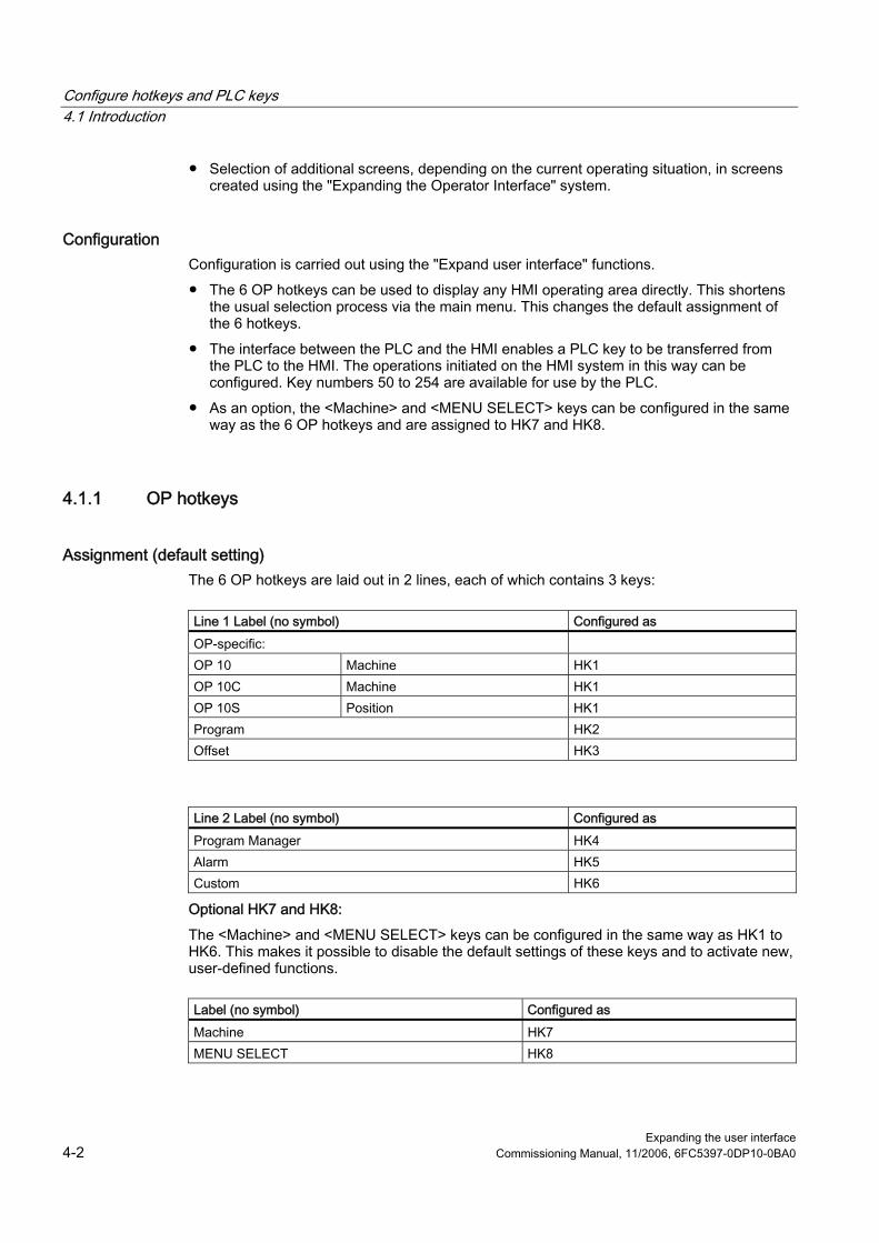
Configure hotkeys and PLC keys 4.1 Introduction
Expanding the user interface 4-2 Commissioning Manual, 11/2006, 6FC5397-0DP10-0BA0
● Selection of additional screens, depending on the current operating situation, in screens created using the "Expanding the Operator Interface" system.
Configuration Configuration is carried out using the "Expand user interface" functions. ● The 6 OP hotkeys can be used to display any HMI operating area directly. This shortens
the usual selection process via the main menu. This changes the default assignment of the 6 hotkeys.
● The interface between the PLC and the HMI enables a PLC key to be transferred from the PLC to the HMI. The operations initiated on the HMI system in this way can be configured. Key numbers 50 to 254 are available for use by the PLC.
● As an option, the <Machine> and <MENU SELECT> keys can be configured in the same way as the 6 OP hotkeys and are assigned to HK7 and HK8.
4.1.1 OP hotkeys
Assignment (default setting) The 6 OP hotkeys are laid out in 2 lines, each of which contains 3 keys:
Line 1 Label (no symbol) Configured as OP-specific: OP 10 Machine HK1 OP 10C Machine HK1 OP 10S Position HK1 Program HK2 Offset HK3
Line 2 Label (no symbol) Configured as Program Manager HK4 Alarm HK5 Custom HK6
Optional HK7 and HK8: The <Machine> and <MENU SELECT> keys can be configured in the same way as HK1 to HK6. This makes it possible to disable the default settings of these keys and to activate new, user-defined functions.
Label (no symbol) Configured as Machine HK7 MENU SELECT HK8
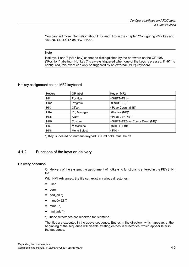
Configure hotkeys and PLC keys 4.1 Introduction
Expanding the user interface Commissioning Manual, 11/2006, 6FC5397-0DP10-0BA0 4-3
You can find more information about HK7 and HK8 in the chapter "Configuring <M> key and <MENU SELECT> as HK7, HK8".
Note Hotkeys 1 and 7 (<M> key) cannot be distinguished by the hardware on the OP 10S ("Position" labeling). Hot key 7 is always triggered when one of the keys is pressed. If HK1 is configured, this event can only be triggered by an external (MF2) keyboard.
Hotkey assignment on the MF2 keyboard
Hotkey OP label Key on MF2 HK1 Position <SHIFT+F11> HK2 Program <END> (NB)* HK3 Offset <Page Down> (NB)* HK4 Prg.Manager <Home> (NB)* HK5 Alarm <Page Up> (NB)* HK6 Custom <SHIFT+F12> or Cursor Down (NB)* HK7 M Machine <SHIFT+F10> HK8 Menu Select <F10>
*) Key is located on numeric keypad: <NumLock> must be off.
4.1.2 Functions of the keys on delivery
Delivery condition On delivery of the system, the assignment of hotkeys to functions is entered in the KEYS.INI file. With HMI Advanced, the file can exist in various directories: ● user ● oem ● add_on *) ● mmc0w32 *) ● mmc2 *) ● hmi_adv *) *) These directories are reserved for Siemens. The files are executed in the above sequence. Entries in the directory, which appears at the beginning of the sequence will disable existing entries in directories, which appear later in the sequence.

Configure hotkeys and PLC keys 4.2 Configuration
Expanding the user interface 4-4 Commissioning Manual, 11/2006, 6FC5397-0DP10-0BA0
On delivery, the assignments for HK1 to HK6 are stored in KEYS.INI in the mmc2 directory for the standard system:
Key Function HK1 Position Machine operating area, last screen HK2 Program Program operating area, last screen HK3 Offset Parameters operating area, last screen HK4 Prg. manager Main screen programming HK5 Alarm Diagnosis operating area, alarm screen HK6 Custom Default Custom operating area, last screen
(user interface configured by the user)
The assignment for ShopMill/ShopTurn applications is as follows:
Key Function HK1 Position Machine operating area, last screen HK2 Program Program editor, last status HK3 Offset Offset area, last status HK4 Prg. manager Program directory, last status HK5 Alarm Diagnosis operating area, alarm screen HK6 Custom Default Custom operating area, last screen
(user interface configured by the user)
4.2 4.2 Configuration
4.2.1 Configuration overview
Overview Below is a schematic diagram illustrating the associations between configured OP hotkeys and PLC keys and the "Expand user interface" configuration:
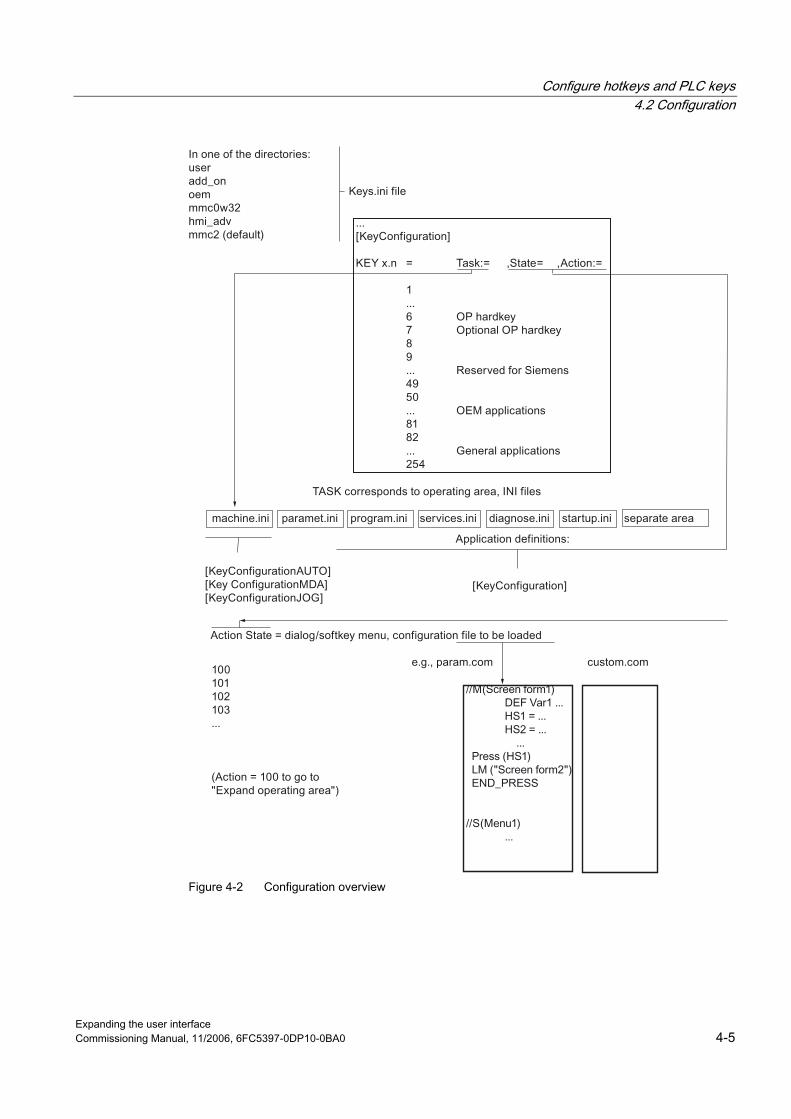
Configure hotkeys and PLC keys 4.2 Configuration
Expanding the user interface Commissioning Manual, 11/2006, 6FC5397-0DP10-0BA0 4-5
Figure 4-2 Configuration overview
Configure hotkeys and PLC keys 4.2 Configuration
Expanding the user interface 4-6 Commissioning Manual, 11/2006, 6FC5397-0DP10-0BA0
4.2.2 Configuration in the KEYS.INI file
Overview Every instance of the KEYS.INI configuration file in the above directories drives the the hotkey responses in a section [KeyConfiguration]. Every entry (line) defines the response of the system to a specific actuation (in the sense of multiple actuation of specific hotkeys). These are referred to as hotkey events below.
KEYS.INI configuration file The KEYS.INI configuration file has a dedicated section for assigning the ini files for PLC keys. Without this entry, the ini files will not be detected. The default settings are as follows:
[HMI_INI_FILES] Task0 = machine.ini Task1 = paramet.ini Task2 = program.ini Task3 = services.ini Task4 = diagnose.ini Task5 = startup.ini Task6 = shopmill.ini (Alternatively: Task6 = shopturn.ini depending on the system, mandatory! ) Task11=custom.ini
Note A power On is required in order for the changes to KEYS.INI to take effect.
Entry format Details about the input format can be found under "Hotkey event". To better understand the repeated actuation of the same hotkey used in that subsection, multiple keypress will be described first.
Multiple keypress A function extension determines the sequence when the hotkey is pressed repeatedly: The number "n" in the key data in file KEYS.INI represents the number of keypress repeats, thus allowing a separate task/state/action combination to be assigned each time the hotkey is pressed. This means that each time the key is pressed, a change of state can take place, and a screen and a softkey can be selected.
Configure hotkeys and PLC keys 4.2 Configuration
Expanding the user interface Commissioning Manual, 11/2006, 6FC5397-0DP10-0BA0 4-7
When the user changes to another operating area, the repeat status of the hotkey is cleared. In the new area, the hotkey is considered not to have been pressed. It does not matter how the user changed to the other operating area (operating area menu, etc.). In addition, each time a function key is pressed (e.g., softkey, area switchover key, channel switchover key, etc.), the status is reset. Inputting data into fields in the current dialog does not interrupt the repetition sequence. Pressing a softkey in the current dialog interrupts the repetition sequence with the softkey that was used to call the current dialog.
Note Multiple keypress is possible for HK1 - HK8 and for keys HK9 - HK49, which are reserved for Siemens.
Example of multiple hotkey keypress The first time the hotkey is pressed, the associated area is activated and a state/action may be initiated in this area (entry 1). Pressing the hotkey again will execute the subsequent entries for this hotkey and an area switchover will not take place. Once all the entries configured for a hotkey have been executed, the cycle is repeated. The entries are always executed in ascending order (from 0-9). Execution in descending order is not possible. There must be no "event gaps" in the configuration (missing entries). A gap is treated like the end of the chain and processing will restart at Key x.0 the next time a key is pressed. Configuration:
[KeyConfiguration] KEY1.0 = Task:=0, State:=10, Action:=2
; Hotkey 1, 1st activation
KEY1.1 = State:=10, Action:=3 ; Hotkey 1, 2nd activation KEY1.2 = Action:=4 ; Hotkey 1, 3rd activation
Entry in the KEYS.INI file for selecting the machine operating area:
KEY1.0 = Task:=0 ; in the last screen the first time the key is pressed
KEY1.1 = Task:=0, State:=0 ; in the start screen the second time the key is pressed
KEY1.2 = State:=0, Action:=3 ; in the start screen the third time the key is pressed and selection of the 3rd softkey
KEY1.3 = State:=0, Action:=100 in the start screen the 4th time the key is pressed and selection of "Expand user interface" function with the configured action ≤ 100 in MACHINE.INI

Configure hotkeys and PLC keys 4.2 Configuration
Expanding the user interface 4-8 Commissioning Manual, 11/2006, 6FC5397-0DP10-0BA0
Assignment of the softkeys to the action values
Horizontal softkeys (SKHi) Action SKH1 0 SKH2 1 SKH3 2 SKH4 3 SKH5 4 SKH6 5 SKH7 6 SKH8 7
Vertical softkeys (SKVi) Action SKV1 8 SKV2 9 SKV3 10 SKV4 11 SKV5 12 SKV6 13 SKV7 14 SKV8 15
Key Action <RECALL> 16 <ETC> (HMI Embedded sl only) 17
4.2.3 Programming a hotkey event
Description The maximum number of attributes, which can be assigned to a hotkey event, is 4. The KEY key attribute identifies the event and must always come first. All other attributes are optional, but at least one other attribute must be specified. These attributes can appear in any sequence in the line.
Configure hotkeys and PLC keys 4.2 Configuration
Expanding the user interface Commissioning Manual, 11/2006, 6FC5397-0DP10-0BA0 4-9
Programming a hotkey event
Syntax: KEYx.n = Task:=task, State:=state, Action:=action Parameters: Key (HotKey) The value x contains the hotkey number x and a
discrete event n corresponding to the nth activation of the key (when the key is pressed several times in succession). The range of values of the hotkey number goes from 1 to 254. The range of values for the event n goes from 0 to 9 (10 keystrokes) Hotkeys 1 to 8 are assigned to the keys of the OPs. Hotkeys 9 to 49 are reserved for Siemens. PLC-specific keys from 50 to 254 are also available. These keys are not actual hotkeys, but are used for selecting screens via the PLC (virtual keys). Keys 50 to 254 can also be configured without a task. In this case, the event is always assigned to the current task.
Task (Operating area) A hotkey is assigned to an operating area (task) via a task number. The task number also defines the horizontal softkey to which the operating area is assigned in the area switchover menu. This creates a permanent connection between the task number and the corresponding softkey. In the HMI system, there are three softkey menus (two in HMI Embedded sl) reserved for the area switchover function.
The default assignments are as follows: Pressing the area switchover key selects softkey menu 1. SK1 → Task0 ... SK8 → Task7 Pressing the <ETC> key again accesses softkey menu 2 SK1 → Task8 ... SK8 → Task15 Pressing the <ETC> key again accesses softkey menu 3 (only possible in HMI Advanced): SK1 → Task16 ... SK8 → Task23

Configure hotkeys and PLC keys 4.2 Configuration
Expanding the user interface 4-10 Commissioning Manual, 11/2006, 6FC5397-0DP10-0BA0
Pressing the <ETC> key again returns to softkey menu 1. In HMI Advanced, the range of values for the task numbers is between 0 and 23, in HMI Embedded it is between 0 and 15. If no task is specified, the event is assigned to the current task (current operating area). The task numbers can be accessed: • From the REGIE.INI file for HMI Advanced. • With the SCK (Software Configuration Kit) tool
in HMI Embedded sl. An application-specific assignment between SKs and operating areas (tasks) can be preset during configuration: • HMI Advanced:
[TaskConfiguration] section in the REGIE.INI file
• HMI Embedded sl: SCK "Modify configuration" State The State attribute can be used to select a specific
screen within a task. The range of values depends on the individual application and is limited to between 0 and 65534 (65535 is used by the system).
Action The Action attribute can be used to select a specific softkey within a task. In order to be effective, the attribute must be set from a defined state, e.g., the main menu. The range of values depends on the corresponding application, with a maximum of between 0 and 17. A special role is played by the Action attribute with a value ≥ 100, which initiates a screen selection via "Expand user interface". Actions in the value range 0 - 99 are not executed for ShopMill/ShopTurn.
See also: Chapter "List of selectable states"
4.2.4 Expansions and special cases
Configuring the M key and Menu Select as HK7, HK8 The <M> key (Machine) and <MENU SELECT> key can be optionally configured as hotkeys. Doing so causes these keys to lose their original definition and function. The new functionality is defined by the KEYS.INI configuration file. If there is a definition in the
Configure hotkeys and PLC keys 4.2 Configuration
Expanding the user interface Commissioning Manual, 11/2006, 6FC5397-0DP10-0BA0 4-11
configuration file for the key, but no response was saved, then the key does not have a function. Hotkey assignment:
MF2 keyboard Hotkey
Key <Machine> SHIFT+F10 HK7
Key <MENU SELECT> F10 HK8
If there is no entry in the keys.ini configuration file for hotkey 7 or hotkey 8, the key will not be mapped as a hotkey but will retain its original function (compatible mode). A key definition without a response will be assigned the <empty> attribute. Example:
[KeyConfiguration] Key7.0 = Task:= 3, State := 10 ; Activate mapping of the <M> key
to hotkey 7 and define new� key reaction
; Activate mapping of the <MENU SELECT> key (F10) to �hotkey 8�; key has no function
Key8.0 = <empty> ; No reaction assigned
Expanded functions in HMI Advanced The machine manufacturer can overload the entries in KEYS.INI in directory mmc2 with custom settings. These settings can be entered in the /user or /oem directories searched earlier during execution. Only deviations in the settings must be stored, not the complete block.
Special cases for Action in HMI Advanced: The <ETC> key, Action 17, has no effect.
Special cases in HMI Embedded sl Special cases Task, State, and Action: ● The range of values for the Task is limited to between 0 and 15. ● HMI Embedded sl always selects the last screen combination that was active before the
task change (state not configured). ● The range of values for State is limited to 0. Only the main menu of the operating area
can be selected. ● The range of values for Action is restricted to between 0 and 17 for:
– Horizontal SK 1 to 8 – Vertical SK 1 to 8 – Recall – ETC

Configure hotkeys and PLC keys 4.3 PLC interface
Expanding the user interface 4-12 Commissioning Manual, 11/2006, 6FC5397-0DP10-0BA0
4.2.5 Expanded functions for PLC keys
Overview Changes of task and state can also be configured for PLC keys.
Range for Action: For standard applications 0 – 17 For "Expand user interface" applications ≥100
The PLC-specific keys have numbers between 50 and 254, with numbers 50 to 81 reserved for OEM applications. Examples: ● The configuration shown here does not execute a change of task or state and, therefore,
remains in the current task and screen. An Action 100 is forwarded. [KeyConfiguration] HK50.0 = Action:=100
● A change of task and state could be configured here in exactly the same way. HK50.0 = Task:=1, State:=10, Action:=100
4.3 4.3 PLC interface
4.3.1 Structure of the interface
Overview In the PLC interface, area DB19. Byte10 is provided for key selection. Here, the PLC can directly select one key between 50 and 254. (Keys 1 to 49 are reserved for Siemens, keys 50 to 254 are specific PLC keys.)
Note In M:N mode, the area for the 2nd HMI interface is DB19.Byte60.
Configure hotkeys and PLC keys 4.3 PLC interface
Expanding the user interface Commissioning Manual, 11/2006, 6FC5397-0DP10-0BA0 4-13
Acknowledgment An HMI system acknowledgment is divided into two steps: ● In the first step, the HMI software transfers the control information 255 to DB19.Byte10. ● In the second step, the actual acknowledgment takes place on the PLC in which
DB19.Byte10 is cleared. This is necessary in order that, despite the lack of synchronism between the HMI and the PLC, the same key code transferred twice in immediate succession can be detected by the HMI. This defined virtual key activation enables the HMI to identify every PLC key sequence uniquely. The control information is of no significance to the PLC program (transparent) and must not be changed.
Next key input If the transfer byte is set to 0, the PLC program can specify a new key. The current key request is processed in parallel in the HMI system. The request leads to a switchover to the corresponding task or initiates a state/action command in the current task. If the task switchover cannot be executed, the operator interface will send a message to indicate this.
Requirements of the PLC program A new request can only be set if the HMI system has acknowledged the previous request (0 in the interface). If the PLC program is deriving the key from a machine control panel key or from another source, it must provide sufficient intermediate storage for the key to ensure that no data is lost if the key is pressed very quickly.
Selecting dialogs from PLC There is an interface between the PLC and HMI Embedded sl for selecting dialogs. These PLC dialogs offer the same means of display and functions as for the dialogs selected via the softkeys.
4.3.2 Description of the PLC display selection
Description of the interface The interface contains the display number, control bits from the PLC to the HMI and control bits from the HMI to the PLC. The interface requires a total of 8 bytes in DB19, 4 bytes for each HMI Embedded sl. Because each NCU can be addressed by up to two HMI Embedded sls at the same time in systems with "multiple operator panel fronts and multiple NCUs", this interface can exist in duplicate. References: /FB2/, "Multiple operator panel fronts and multiple NCUs" (B3)

Configure hotkeys and PLC keys 4.3 PLC interface
Expanding the user interface 4-14 Commissioning Manual, 11/2006, 6FC5397-0DP10-0BA0
Structure of the interface The interface between HMI Embedded sl and the PLC uses the following data:
HMI 1: DB19.DBW28: Screen number DB19.DBB30: Control bits PLC → HMI, PLC byte DB19.DBB31: Control bits HMI → PLC, HMI byte HMI 2: DB19.DBW28: Screen number DB19.DBB80: Control bits PLC → HMI, PLC byte DB19.DBB81: Control bits HMI → PLC, HMI byte
PLC-Byte Bit0 Display selection Bit1 Display selection HMI byte Bit0 Display selection or display deselection accepted Bit1 Display is being selected or deselected Bit2 Display is selected Bit3 Display is deselected Bit4 Error, display selection not possible Bit7 Inactive bit
Two bytes are used for the display number to be transferred by the PLC; these are one PLC byte and one HMI byte for coordinating the display selection.
Operating the interface The interface is operated by the PLC program supplied by the manufacturer, using the following functions (DB 19 extract, first HMI interface):
PLC → HMI Selection Deselection HMI → PLC Selection Deselection DBW 28 Screen number (1) Bit DBB 30 DBB 31 0 Display selection 1 (2)
0 (4) Select/deselect
accepted 1 (3) 0 (6)
1 (2) 0 (3)
1 Display deselection 1 (1) 0 (4)
Display is being selected Display is being deselected
0 (3) 1 (5)
0 (3)
2 Display is selected 0 (3) 1 (7)
0 (3)
3 Display is deselected 0 (3) 0 (2) 1 (3)
4 Error, display selection not possible
0 0 (2)

Configure hotkeys and PLC keys 4.3 PLC interface
Expanding the user interface Commissioning Manual, 11/2006, 6FC5397-0DP10-0BA0 4-15
PLC → HMI Selection Deselection HMI → PLC Selection Deselection 5 − 6 − 7 Inactive 0
Display selection The relations with the individual steps are shown in the above table by the numbers in brackets (step numbers). ● The PLC enters the display number in the number word. ● The PLC sets bit0 in the PLC byte for display selection if bit0 and bit7 are set to zero in
the HMI byte. ● HMI Embedded sl acknowledges to the PLC that it has accepted the display selection by
setting bit0 in the HMI byte. At the same time, the value zero is written to bit3 and bit4 in the HMI byte.
● The PLC resets bit0 in the PLC byte. ● HMI Embedded sl acknowledges to the PLC that the interpreter has started by setting
bit1 in the HMI byte. ● The HMI resets bit0 in the HMI Embedded sl byte. ● Bit2 is set in the HMI byte if the corresponding display appears.
Display deselection The relations with the individual steps are shown in the above table by the numbers in brackets (step numbers). ● The PLC sets bit1 for display deselection in the PLC byte if bit1 and bit2 are set in the
HMI byte and bit7 is reset. ● HMI Embedded sl acknowledges to the PLC that it has accepted the display deselection
by setting bit0 in the HMI byte. At the same time, the value zero is written to bit3 and bit4 in the HMI byte.
● HMI Embedded sl acknowledges the display deselection to the PLC by setting bit3 and resetting bit0, bit1 and bit2 in the HMI byte if the interpreter is terminated.
● The PLC resets bit1 in the PLC byte. ● After display deselection by the PLC or the EXIT command, HMI Embedded sl switches
back to the last selected HMI display.
Error when selecting a display Bit4 is set in the HMI byte if the interpreter has not responded after 20 seconds or if the required display cannot be opened. The states of the HMI that do not support PLC display selection are indicated to the PLC via bit7 in the HMI byte; e.g., in HMI Embedded sl during switchover between standard and ShopMill/ShopTurn interface.

Configure hotkeys and PLC keys 4.3 PLC interface
Expanding the user interface 4-16 Commissioning Manual, 11/2006, 6FC5397-0DP10-0BA0
Operating areas With HMI Advanced, the displays are shown in a separate operating area similar to the measuring cycle displays. This operating area can be selected manually by means of the sixth softkey (PLC displays) on the second operating area menu. If no PLC display is active when the area is selected, the text "Currently no PLC display active" is displayed in the header. The PLC is informed when the area is selected/deselected manually via bit2 of the HMI byte. It is also possible to change to other operating areas via the MMC 103's operating area after a display has been selected by the PLC. With HMI Embedded sl, it is not possible to manually select/deselect displays selected by the PLC via an operating area. The PLC display remains in the foreground even after a change of operating area has occurred.
4.3.3 Configuring the dialog selection
Description The interface is activated by means of the section [PLC_SELECT] in the COMMON.COM file during HMI boot. The display number is assigned to the configured display in the section [PLC_SELECT] of the COMMON.COM file.
Configuration
Syntax: PCi = Display name, date, comment Description: Assigns display number to configured display Parameters: i Number of the display in the interface Display name Dialog identifier File File in which the dialog is configured Comment Comment on dialog
Example
[PLC_SELECT] PC1= CYC82, drilling.com ; Assignment line PC2= CYCLE90, millthre.com PC3= ...
See also Search function for COMMON.COM (Page 6-13)

Configure hotkeys and PLC keys 4.4 Selecting dialog/softkey menus
Expanding the user interface Commissioning Manual, 11/2006, 6FC5397-0DP10-0BA0 4-17
4.4 4.4 Selecting dialog/softkey menus
4.4.1 Assigning INI files to operating areas
Overview An Action value ≥ 100 automatically switches the HMI software to "Expand user interface" operational sequences. If Action ≥ 100, the configuration of the INI files determines which softkey menu or screen form should be displayed and in which state.
HMI Advanced/HMI Embedded sl The following INI files and sections can be configured for the jump entry to "Expand user interface":
Operating area File Section Machine machine.ini [KeyConfigurationAuto]
[KeyConfigurationMDA] [KeyConfigurationJOG]
Parameter paramet.ini [KeyConfiguration] Program program.ini [KeyConfiguration] Services services.ini [KeyConfiguration] Diagnostics diagnosis.ini [KeyConfiguration] Start-up startup.ini [KeyConfiguration] Custom custom.ini [KeyConfiguration]
ShopMill on NCU/ ShopTurn on NCU In the case of ShopMill and ShopTurn on NCU, the files are accordingly named SHOPMILL.INI and SHOPTURN.INI. The following sections, in which "Expand user interface" functions can be configured, are parts of these files: [MachineManual] ... [MachineAutomatic] ... [ProgramManager] ... [Program] ... [MessagesAlarms] ... [ToolsZeroOffset]
Configure hotkeys and PLC keys 4.4 Selecting dialog/softkey menus
Expanding the user interface 4-18 Commissioning Manual, 11/2006, 6FC5397-0DP10-0BA0
... [MachineMDI]
4.4.2 Configuring "Expand user interface" functions
Description One or more states (according to the State list) can be configured for each action (≥ 100) and you can also specify which "Expand user interface" function is to be initiated. If nothing is configured in these INI files, no screen forms or softkey menus will appear.
Programming Action.State
Syntax: Action.State = Dialog/softkey menu to be loaded, configuration file Parameters: Action The action is Action ≥ = 100 configured in KEYS.INI. State State in which the application is presently in Configuration file File in which the configuration is stored. LS/LM "Expand user interface" commands for loading
softkeys/dialogs
Examples [KeyConfiguration] 100.10=LS("Softkey1","param.com") 100.30=LM("Form1","param.com") 101.10=LS("Softkey1","param.com") 101.30=LM("Form2","param.com") 102=LM("Form2","param1.com") Explanations: ● For the first line, for example, this means:
If an Action 100 is initiated when in state (status/screen) 10, the softkey menu configured in the param.com file will be displayed with the name Softkey1.
● For the last line, for example, this means: If Action 102 is initiated, the dialog with the name Screen form2 will be called in the current dialog. This dialog is configured in the param1.com file.

Configure hotkeys and PLC keys 4.5 List of selectable states
Expanding the user interface Commissioning Manual, 11/2006, 6FC5397-0DP10-0BA0 4-19
4.5 4.5 List of selectable states
4.5.1 Selectable states in HMI Advanced
Overview In general, the following conditions apply to all tasks in HMI Advanced:
No configuration: Maintains current state. Configuration with 0: The basic state of an operating area is activated.
"Machine" operating area In the Machine operating area, the status is always dependent on the status of the machine (AUTO, MDA, JOG, REF). The following can be selected via the PLC key: ● The main screen for the relevant mode
State BAG Machine function Display 0 JOG REF JOG/REF main screen 0 JOG none JOG main screen 0 JOG REPOS REPOS main screen 0 MDI none MDA start screen 0 MDI TEACH MDA/Teach main screen 0 MDI REF MDA/REF main screen 0 AUTO none Auto main screen
● The main actual value screens for each mode (softkey vertical 6)
State BAG Machine function Display 10 JOG none Zoom actual values JOG 20 MDI none Zoom actual values MDA 30 AUTO none Zoom actual values Auto
● Possibly still in JOG / MDA
Switching between the WCS and MCS is possible via the PLC.
State BAG Machine function Display 60 JOG none Handwheel selection JOG 70 JOG none Increment selection JOG 80 MDI none Handwheel selection MDA

Configure hotkeys and PLC keys 4.5 List of selectable states
Expanding the user interface 4-20 Commissioning Manual, 11/2006, 6FC5397-0DP10-0BA0
"Parameters" operating area It is not possible to move from the current screen in this area.
"Program" operating area
State Function 10 Data selection 20 Program management 70 Log
Services operating area
State Function 10 Data in 20 Data out 40 Manage data 60 Data selection 80 External drives 90 Series startup 100 upgrading
Diagnostics operating area The diagnostics main screen is the alarm overview. The following horizontal softkeys can be used to access other states from this state:
State Function 10 Alarms 20 Alarms 30 Alarm log 40 Service displays 50 PLC status
Messages, alarm log and service displays can always be accessed.
Startup operating area The startup main screen is an overview of the available NC axes and drives.
State Function 0 NC axes and drives 10 Machine data 40 PLC status

Configure hotkeys and PLC keys 4.5 List of selectable states
Expanding the user interface Commissioning Manual, 11/2006, 6FC5397-0DP10-0BA0 4-21
State Function 50 Optimization/test (V7.1 and later) 60 HMI
Custom operating area See chapter "Custom operating area".
4.5.2 Selectable states in HMI Embedded sl
Overview There are the following configuration options for the state in HMI Embedded sl:
A configuration: Maintains current state. Configuration with 0: The basic state of an operating area is activated.
4.5.3 Selectable states in ShopMill on NCU
Machine Manual
Legend: * If option available (display MD is set) Custom screen These designated functions can be configured with the "Expanding the
Operator Interface" system. If this type of configuration is available, it is activated. Otherwise, the standard ShopMill screen will appear.
State Function 19 Main screen 2 T, S, M, etc. 30 Workpiece zero 5 Workpiece zero - set up edge 7 Workpiece zero – /user screen form 31 Workpiece zero – align edge/user screen form 32 Workpiece zero – spacing 2 edges/user screen form 33 Workpiece zero – rectangular edge 8 Workpiece zero – arbitrary edge/user screen form 34 Workpiece zero – rectangular pocket 9 Workpiece zero – 1 hole/user screen form

Configure hotkeys and PLC keys 4.5 List of selectable states
Expanding the user interface 4-22 Commissioning Manual, 11/2006, 6FC5397-0DP10-0BA0
State Function 35 Workpiece zero – 2 holes 36 Workpiece zero – 3 holes 37 Workpiece zero – 4 holes 38 Workpiece zero – rectangular spigot 10 Workpiece zero – 1 circular spigot /user screen form 39 Workpiece zero – 2 circular spigots 40 Workpiece zero – 3 circular spigots 41 Workpiece zero – 4 circular spigots 42 Workpiece zero - set up plane 11 Workpiece zero – calibration probe, length*/user screen form 12 Workpiece zero – calibration probe, radius* 50 Measure tool 16 Tool gauging – length manual/user screen form 17 Tool gauging – diameter/user screen form 13 Tool gauging – length auto*/user screen form 14 Tool gauging – diameter auto*/user screen form 51 Measure tool – /user screen form 15 Measure tool – calibration probe*/user screen form 52 Measure tool – calibration fixed point*/user screen form 60 Swiveling* 4 Position 18 Face milling 1 ShopMill settings 90 – /user screen form
MDI
State Function 20 MDI
Machine Auto
State Function 200 Main screen 210 Program control 220 Block search 230 – /user screen form 242 Simultaneous recording – top view* 243 Simultaneous recording – 3-plane view* 244 Simultaneous recording – volume model* 250 Settings

Configure hotkeys and PLC keys 4.5 List of selectable states
Expanding the user interface Commissioning Manual, 11/2006, 6FC5397-0DP10-0BA0 4-23
Program Manager
State Function 300 NC directory 310 Parts programs* 320 Subprograms* 330 User directory 1 * 340 User directory 2 * 350 User directory 3 * 360 User directory 4 * 380 Standard cycles* 381 Manufacturer cycles* 382 User cycles* 383 User directory 5 * 384 User directory 6 * 385 User directory 7 * 386 User directory 8 *
Program
State Function 400 Machining plan / G code editor 412 Simulation – top view* 413 Simulation – 3-plane view* 414 Simulation – volume model*
Messages/alarms
State Function 500 Alarms 510 – /user screen form 520 – /user screen form
Tools/zero offsets
State Function 600 Tool list 610 Tool wear 620 User tools list* 630 Magazine 640 Zero point shift 650 R parameters

Configure hotkeys and PLC keys 4.5 List of selectable states
Expanding the user interface 4-24 Commissioning Manual, 11/2006, 6FC5397-0DP10-0BA0
State Function 660 – /user screen form 680 User data 690 Machine data
4.5.4 Selectable states in ShopTurn on NCU
Machine manual (without "Machine manual" option)
Legend: * If option available (display MD is set) Custom screen These designated functions can be configured with the "Expanding the
Operator Interface" system. If this type of configuration is available, it is activated. Otherwise, the standard ShopMill screen will appear.
State Function 19 Main screen 2 T, S, M, etc. 30 Workpiece zero 31 Workpiece zero – /user screen form 34 Workpiece zero – /user screen form 35 Workpiece zero – /user screen form 36 Workpiece zero – /user screen form 37 Workpiece zero – /user screen form 38 Workpiece zero – /user screen form 40 Workpiece zero – /user screen form 5 Workpiece zero – measure edge Z 50 Measure tool 51 Measure tool – length manual X/user screen form 52 Measure tool – length manual Z/user screen form 53 Measure tool – zoom*/user screen form 54 Measure tool – /user screen form 55 Measure tool – /user screen form 56 Measure tool – calibration probe*/user screen form 57 Measure tool – /user screen form 58 Measure tool – automatic Z * 59 Measure tool – automatic X * 4 Position 18 Face milling* 80 Cutting*
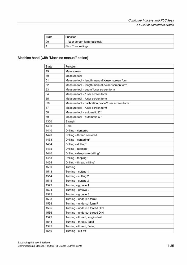
Configure hotkeys and PLC keys 4.5 List of selectable states
Expanding the user interface Commissioning Manual, 11/2006, 6FC5397-0DP10-0BA0 4-25
State Function 90 – /user screen form (tailstock) 1 ShopTurn settings
Machine hand (with "Machine manual" option)
State Function 19 Main screen 50 Measure tool 51 Measure tool – length manual X/user screen form 52 Measure tool – length manual Z/user screen form 53 Measure tool – zoom*/user screen form 54 Measure tool – /user screen form 55 Measure tool – /user screen form 56 Measure tool – calibration probe*/user screen form 57 Measure tool – /user screen form 58 Measure tool – automatic Z * 59 Measure tool – automatic X * 1300 Straight 1400 Bore 1410 Drilling – centered 1420 Drilling – thread centered 1433 Drilling – centering* 1434 Drilling – drilling* 1435 Drilling – reaming* 1440 Drilling – deep-hole drilling* 1453 Drilling – tapping* 1454 Drilling – thread milling* 1500 Turning 1513 Turning – cutting 1 1514 Turning – cutting 2 1515 Turning – cutting 3 1523 Turning – groove 1 1524 Turning – groove 2 1525 Turning – groove 3 1533 Turning – undercut form E 1534 Turning – undercut form F 1535 Turning – undercut thread DIN 1536 Turning – undercut thread DIN 1543 Turning – thread, longitudinal 1544 Turning – thread, taper 1545 Turning – thread, facing 1550 Turning – cut-off

Configure hotkeys and PLC keys 4.5 List of selectable states
Expanding the user interface 4-26 Commissioning Manual, 11/2006, 6FC5397-0DP10-0BA0
State Function 1600 Milling* 1613 Milling – rectangular pocket* 1614 Milling – circular pocket* 1623 Milling – rectangular spigot* 1624 Milling – circular spigot* 1633 Milling – longitudinal groove* 1634 Milling – circumferential groove* 1640 Milling – polyhedron* 1670 Milling – engraving* 1730 Simulation – 3-window view* 1740 Simulation – side view* 1750 Simulation – front view* 90 – /user screen form (tailstock) 1 ShopTurn settings
MDI
State Function 20 MDI
Machine Auto
State Function 200 Current block display 210 Program control 220 Block search 230 – /user screen form 242 Simultaneous recording – 3-window view* 243 Simultaneous recording – side view* 244 Simultaneous recording – front view* 250 Settings
Program Manager
State Function 300 NC directory 310 Parts programs* 320 Subprograms* 330 User directory 1 * 340 User directory 2 * 350 User directory 3 *

Configure hotkeys and PLC keys 4.5 List of selectable states
Expanding the user interface Commissioning Manual, 11/2006, 6FC5397-0DP10-0BA0 4-27
State Function 360 User directory 4 * 380 Standard cycles* 381 Manufacturer cycles* 382 User cycles* 383 User directory 5 * 384 User directory 6 * 385 User directory 7 * 386 User directory 8 *
Program
State Function 400 Machining plan / G code editor 412 Simulation – 3-window view* 413 Simulation – side view* 414 Simulation – front view*
Messages/alarms
State Function 500 Alarms 510 – /user screen form 520 – /user screen form
Tools/zero offsets
State Function 600 Tool list 610 Tool wear 620 OEM tool list* 630 Magazine 640 Zero point shift 650 R parameters 660 – /user screen form 670 Spindles 680 User data 690 Machine data

Configure hotkeys and PLC keys 4.5 List of selectable states
Expanding the user interface 4-28 Commissioning Manual, 11/2006, 6FC5397-0DP10-0BA0
Expanding the user interface Commissioning Manual, 11/2006, 6FC5397-0DP10-0BA0 5-1
"Custom" operating area 55.1 5.1 Delivery condition and use
Overview The operating areas described thus far can be extended and modified using "Expanding the Operator Interface" tools. Extensions can only be applied to softkeys, which have not been used previously. Using the tools described below, it is possible to configure a separate operating area in both HMI Embedded sl and HMI Advanced, where all 8 horizontal and 8 vertical softkeys are available for a user-specific user interface. The default name of this operating area is "Custom". On OPs with hotkey block (e.g., OP 010, OP 010C), the "Custom" operating area can be directly selected with: ● "Custom" hotkey ● Softkey 4 in the 1st horizontal expanded menu (default setting)
Condition on delivery The "Custom" operating area displays an empty window with a configurable header across the whole area of the local menu. The "Custom" operating area also permits a configurable text in the operating area display field in the global menu. All softkeys are empty and can be assigned as required by the customer using "Expand user interface". When switching from and back to the "Custom" area, the screen active before exiting the "Custom" operating area is active. ● HMI Advanced
The "Custom" operating area is available by default on delivery and can be reset via an entry in the REGIE.INI file or assigned to any other horizontal softkey.
● HMI Embedded sl The "Custom" operating area is available by default. It is supplied with the application diskette and can be assigned to any horizontal softkey by the customer using the Software Configuration Kit (SCK.exe).
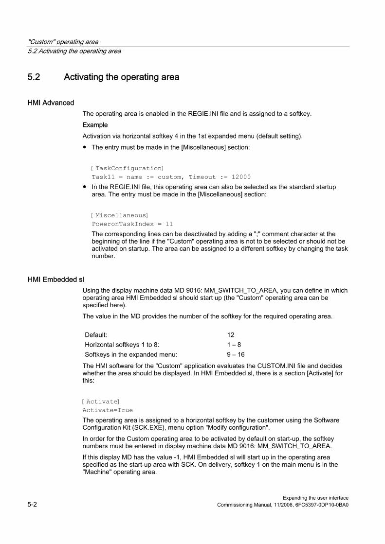
"Custom" operating area 5.2 Activating the operating area
Expanding the user interface 5-2 Commissioning Manual, 11/2006, 6FC5397-0DP10-0BA0
5.2 5.2 Activating the operating area
HMI Advanced The operating area is enabled in the REGIE.INI file and is assigned to a softkey. Example Activation via horizontal softkey 4 in the 1st expanded menu (default setting). ● The entry must be made in the [Miscellaneous] section:
[TaskConfiguration] Task11 = name := custom, Timeout := 12000
● In the REGIE.INI file, this operating area can also be selected as the standard startup area. The entry must be made in the [Miscellaneous] section: [Miscellaneous] PoweronTaskIndex = 11 The corresponding lines can be deactivated by adding a ";" comment character at the beginning of the line if the "Custom" operating area is not to be selected or should not be activated on startup. The area can be assigned to a different softkey by changing the task number.
HMI Embedded sl Using the display machine data MD 9016: MM_SWITCH_TO_AREA, you can define in which operating area HMI Embedded sl should start up (the "Custom" operating area can be specified here). The value in the MD provides the number of the softkey for the required operating area.
Default: 12 Horizontal softkeys 1 to 8: 1 – 8 Softkeys in the expanded menu: 9 – 16
The HMI software for the "Custom" application evaluates the CUSTOM.INI file and decides whether the area should be displayed. In HMI Embedded sl, there is a section [Activate] for this: [Activate] Activate=True The operating area is assigned to a horizontal softkey by the customer using the Software Configuration Kit (SCK.EXE), menu option "Modify configuration". In order for the Custom operating area to be activated by default on start-up, the softkey numbers must be entered in display machine data MD 9016: MM_SWITCH_TO_AREA. If this display MD has the value -1, HMI Embedded sl will start up in the operating area specified as the start-up area with SCK. On delivery, softkey 1 on the main menu is in the "Machine" operating area.

"Custom" operating area 5.3 Defining the start dialog
Expanding the user interface Commissioning Manual, 11/2006, 6FC5397-0DP10-0BA0 5-3
Activation by keys ● Hotkey
The "Custom" hotkey on the OP 010 and OP 010C always activates this operating area (default setting). Other additional configurations are possible.
● Horizontal softkey Activation via the horizontal softkey 4 in the 1st expanded menu is the default setting. The softkey assignment can be changed in HMI Advanced; in HMI Embedded sl, this is done with the help of the Software Configuration Kit (SCK).
Behavior during operating area change When you change from the "Custom" operating area to another operating area and back again, the window that was active when you closed the "Custom" operating area reappears the next time you open it.
5.3 5.3 Defining the start dialog
Overview The inputs in the CUSTOM.INI file are used to define the start dialog and those in the RE_xx.INI file for the operating area name in HMI Advanced. ● Dialog header
A text with the dialog header can be entered in this section [Header]. This can be in the form of either text or an alarm text number, which will make the header language-dependent: [Header] Text="XY special functions" Text=$80XXX Default setting: Text = "Custom"
● Picture in start dialog In the [Picture] section, it is possible to enter a path to a picture that is displayed at the start of the application: [Picture] Picture=\directory\bild.bmp

"Custom" operating area 5.3 Defining the start dialog
Expanding the user interface 5-4 Commissioning Manual, 11/2006, 6FC5397-0DP10-0BA0
● Operating area name
HMI Advanced HMI Embedded sl The name specified appears on the top left of the start dialog displayed. [HSoftkeyTexts] HSK11 = "Custom"
The name specified appears on the top left of the start dialog displayed. [Task name] Notation: Text = $80xxx
● Softkey labels
HMI Advanced HMI Embedded sl The name entered as the operating area name in the RE_xx.INI file is also displayed on the configured softkey. "xx" stands for the language code.
The text entered is displayed on the softkey assigned. If nothing has been entered, "Custom" will appear as the default setting. [Softkey] Text = $80xxx
All other elements in the "Custom" operating area, such as softkey menus or input/output fields and the relevant functions, must be configured using the "Expand user interface" tools. In the "Custom" application all softkeys are available as "Expand user interface" softkeys. These softkeys are configured in the CUSTOM.COM file (like the standard version of AEDITOR.COM included in the scope of supply) as described below. In HMI Embedded sl, the COMMON.COM file for customer start softkeys must contain references to CUSTOM.COM. The COMMON.COM file is supplied so that all "Custom" operating area softkeys are linked to CUSTOM.COM.

Expanding the user interface Commissioning Manual, 11/2006, 6FC5397-0DP10-0BA0 6-1
Configuring environment 66.1 6.1 Scope of supply
Overview The software that interprets the configuration files for user interfaces and provides or activates the functions described is included in the scope of delivery of the HMI software, along with an ASCII editor for creating the content of the configuration files (program editor).
Products ShopMill on NCU and ShopTurn on NCU are based on HMI Embedded sl. HMI Embedded WIN32 and HMI Advanced can be combined on a single hardware platform. Thus, the operating systems of these products are available as alternatives to HMI Advanced on a single hardware platform.
Differences in the system Because of the differences in the hardware, the configuration files are created in another way: ● HMI Advanced on PCU 50 has a hard disk. ● HMI Embedded sl only has RAM and user memory on the CF card. ● HMI Embedded WIN32 on PCU 50 or PC with Windows evaluates hard disk configuration
files but operates in the same way as HMI Embedded sl in all other respects.
Creating displays If the configured screen forms are to include images, then a suitable graphics program (e.g., MS Paint) will be required.
See also Search function principle (Page 6-10)

Configuring environment 6.2 Creating configuration data
Expanding the user interface 6-2 Commissioning Manual, 11/2006, 6FC5397-0DP10-0BA0
6.2 6.2 Creating configuration data
6.2.1 Using the COMMON.COM file
Overview When using HMI Advanced, no entries are required in the COMMON.COM file. In HMI Embedded sl, this central control file contains the following information: ● Assignment between start softkeys and configuration files ● Assignment of display numbers to configuration files in PLC interface DB19 ● Control entries (size of LOG file, available memory on the temporary directory for
configuration files). Default setting for HMI Advanced/HMI Embedded sl:
Main screen Horizontal softkey Configuration file Machine JOG 1 MA_JOG.COM Machine MDA 1 MA_MDA.COM Machine Automatic 2 MA_AUTO.COM Parameter 7 PARAM.COM Program 8 PROG.COM Services 7 SERVICE.COM Diagnostics 7 DIAG.COM Start-up expanded softkey menu
7 6, 7
STARTUP.COM
Editor (reserved) 2, 3, 4, 5 AEDITOR.COM Editor expanded softkey menu
6 6, 7
AEDITOR.COM
Naming convention and file size ● HMI Embedded sl
All file names must follow DOS conventions (xxxxxxxx.com). The total permissible number of configuration files is 10. Color format for the Help displays: 256-color bitmaps in bmp format. The memory requirement for the displays and configuration files is determined solely by the size of the CF card used. It is not possible to state what the maximum possible number of files can be.
● HMI Advanced Files with the names of the start softkeys are searched for in directories in the order specified above. If files of the same name are stored in different directories, then the first file detected according to the search strategy is interpreted. The sizes of configuration

Configuring environment 6.2 Creating configuration data
Expanding the user interface Commissioning Manual, 11/2006, 6FC5397-0DP10-0BA0 6-3
files are not subject to any particular restrictions. It should be noted, however, that large files are processed more slowly.
6.2.2 Structure of the COMMON.COM file
Overview The COMMON.COM file is supplied together with the cycles. It contains various sections for specific hardware settings. For HMI Embedded sl, section [MMC_DOS] is relevant for the "Expand user interface" system.
Configuring COMMON.COM
Syntax Parameter = Value ; Any number of blanks can be placed between Parameter, the '=' sign and Value.
Description [MMC_DOS] ; Start of the DOS section ; Text contained within a line after a semicolon ; is
treated as a comment and is not evaluated Parameter All parameters are optional. SCxxx=File Softkey connection: Connection between softkey and
configuration file "xxx" represents an internal softkey identity of the start softkey. The softkey identity must be entered directly after SC. Softkeys will not be displayed unless a softkey connection is defined for them.
HCyyy = File Hotkey connection: Connection between hotkey and configuration file. "yyy" represents an internal hotkey identity of the start hotkey. The hotkey identity must be entered directly after HC. Only hotkeys for which a hotkey connection has been defined have an effect.
File The configuration file, which contains the softkey and dialog definitions. File names may not exceed a length of 8 characters. The file extension is added with a dot. Example SC101= my_file.com ; (my_file.com on HMI, NC)
Note Changes to COMMON.COM only take effect following a restart.

Configuring environment 6.2 Creating configuration data
Expanding the user interface 6-4 Commissioning Manual, 11/2006, 6FC5397-0DP10-0BA0
Control entries
Syntax: CHK_FILE_EXIST=ram Identifiers: This control flag: specifies whether configuration files must be copied
each time by the NC or whether a check must be made as to whether the files are already stored on the RAM drive of the HMI.
Parameters: ram Possible values: 0: A check whether the file already exists on the
temporary drive is not carried out. This mode is only set while the configuration files are being set up online on the NC. Changes to configuration files in the NC then become operative immediately on the HMI Embedded sl, slowing down the display building process.
1: Default setting (if CHK_FILE_EXIST has not been set): The configuration files are read once into the temporary directory and executed thereafter from there. This means Runtime is improved, but there is no reaction to changes in the configuration files in the NC.
Syntax: LOGSIZE=kB Identifiers: A LOG file named ERROR.COM is created on the temporary directory of
the HMI; its size is determined by this parameter setting. Parameters: KB Size of the LOG file in kilobytes (max. size = 64 KB).
Syntax: RAMDISK_SIZE = kBrd Identifiers: RAMDISK_SIZE can be located at any position - within or outside the
sections. If the element occurs several times, then the first occurrence is relevant. If, after copying, the selected size has been exceeded, all of the COM files in the temporary directory are deleted before the next copying operation. (Files for dialogs in the background for operating area change are retained.)
Parameters: kBrd Size of available RAMDISK in KB. Default: 300 KB (if the RAMDISK_SIZE element was not specified)

Configuring environment 6.2 Creating configuration data
Expanding the user interface Commissioning Manual, 11/2006, 6FC5397-0DP10-0BA0 6-5
Example of COMMON.COM
[MMC_DOS] sc101=tooth.com ; MACHINE sc111=mda.com ; The files are stored on the flash memory of
the HMI. sc122=auto.com sc207=param.com ; PARAMETER sc314=aeditor.com ; PROGRAM, Editor sc315=aeditor.com sc316=aeditor.com sc407=dienste.com ; SERVICES sc507=diagnose.com ; DIAGNOSIS sc607=inbetrn.com ; STARTUP sc826=cmm.com ; ShopMill, Machine, AUTO sc857=cmm.com ; Messages / alarms sc858=cmm.com sc867=cmm.com ; Tools, WO CHK_COMMON.COM=1 ; Rapid execution of the HMI LOGSIZE=30 ; Size of the error log (LOG file) 30 KB [PLC_SELECT] ; Notification of displays, which can be called
by the PLC PC1= CYC82, drilling.com ; Fig. 1: PC2= CYCLE90, millthre.com ; Fig. 2:
6.2.3 Configuring start softkeys
Overview The start softkeys named here can be used to activate the associated configuration files. The possible start softkeys for dialogs are predefined. Additional start softkeys are not possible. Start softkeys are specific to operating areas.
Programming
Syntax SCxxx = File Identifier Softkey connection: Connection between softkey and configuration file
"xxx" represents an internal softkey identity of the start softkey. Parameter File Name of configuration file
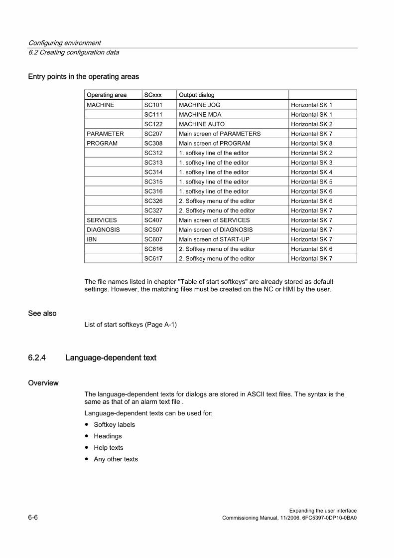
Configuring environment 6.2 Creating configuration data
Expanding the user interface 6-6 Commissioning Manual, 11/2006, 6FC5397-0DP10-0BA0
Entry points in the operating areas
Operating area SCxxx Output dialog MACHINE SC101 MACHINE JOG Horizontal SK 1 SC111 MACHINE MDA Horizontal SK 1 SC122 MACHINE AUTO Horizontal SK 2 PARAMETER SC207 Main screen of PARAMETERS Horizontal SK 7 PROGRAM SC308 Main screen of PROGRAM Horizontal SK 8 SC312 1. softkey line of the editor Horizontal SK 2 SC313 1. softkey line of the editor Horizontal SK 3 SC314 1. softkey line of the editor Horizontal SK 4 SC315 1. softkey line of the editor Horizontal SK 5 SC316 1. softkey line of the editor Horizontal SK 6 SC326 2. Softkey menu of the editor Horizontal SK 6 SC327 2. Softkey menu of the editor Horizontal SK 7 SERVICES SC407 Main screen of SERVICES Horizontal SK 7 DIAGNOSIS SC507 Main screen of DIAGNOSIS Horizontal SK 7 IBN SC607 Main screen of START-UP Horizontal SK 7 SC616 2. Softkey menu of the editor Horizontal SK 6 SC617 2. Softkey menu of the editor Horizontal SK 7
The file names listed in chapter "Table of start softkeys" are already stored as default settings. However, the matching files must be created on the NC or HMI by the user.
See also List of start softkeys (Page A-1)
6.2.4 Language-dependent text
Overview The language-dependent texts for dialogs are stored in ASCII text files. The syntax is the same as that of an alarm text file . Language-dependent texts can be used for: ● Softkey labels ● Headings ● Help texts ● Any other texts

Configuring environment 6.2 Creating configuration data
Expanding the user interface Commissioning Manual, 11/2006, 6FC5397-0DP10-0BA0 6-7
Permissible file names The file names are defined as follows:
Alsc.txt Contains the language-dependent texts for the Siemens standard cycles Almc.txt Contains the language-dependent texts for the manufacturer cycles Aluc.txt Language-dependent user texts
Format of a text entry
Syntax 8xxxx 0 0 "Text" Description Assignment between text number and text in the file Parameter xxxx 5000 to 9899 Text identification number range reserved
for users. You must assign unique numbers.
"text" Text that appears in dialog Parameters 2 and 3 are separated by blanks and act as control characters for alarm text output. To ensure that the text format is identical to that of the alarm texts, these two parameters must always be set to 0. The following control characters may be inserted in text:
%n Line break %@x Axis name of axis x (x is the axis number); HMI Embedded sl only
Show axis names (HMI Embedded sl and HMI Advanced): NC access to corresponding machine data element containing the relevant axis name; text assembly by means of the string functions it contains.
Examples:
85000 0 0 "Retraction plane" 85001 0 0 "Drilling depth" 85002 0 0 "Pitch" 85003 0 0 "Pocket radius"

Configuring environment 6.3 Storage structure of configuration files
Expanding the user interface 6-8 Commissioning Manual, 11/2006, 6FC5397-0DP10-0BA0
6.3 6.3 Storage structure of configuration files
6.3.1 HMI Embedded sl
Storage In the Linux environment, the user configurations are copied to the /user/sinumerik/hmi/proj directory (for "normal" user dialogs, i.e., everything except cycles support) on the CF card. User configurations for user cycles support are copied to the /user/sinumerik/cycles/proj directory on the CF card. All files are unpacked and copied to the relevant directory. Similarly, the manufacturer configurations are copied to the /oem/sinumerik/.... directories.
Path Content /card/oem/sinumerik/hmi/proj User configurations (com files for "normal" user
dialogs, i.e., everything except cycles support) /card/user/sinumerik/cycles/proj User configurations for user cycles support /card/oem/sinumerik/cycles/proj /card/oem/sinumerik/hmi/proj
Manufacturer configurations
/card/user/sinumerik/cycles/ico/icoxxx /card/oem/sinumerik/cycles/ico/icoxxx /card/user/sinumerik/hmi/ico/icoxxx /card/oem/sinumerik/hmi/ico/icoxxx
Bitmaps
/card/user/sinumerik/hmi/cfg /card/oem/sinumerik/hmi/cfg
Ini files
/card/user/sinumerik/hmi/ico/icoxxx /card/oem/sinumerik/hmi/ico/icoxxx
Header icons
/card/user/sinumerik/cycles/lng/xxx /card/oem/sinumerik/cycles/lng/xxx /card/user/sinumerik/hmi/lng/xxx
The relevant texts (aluc.txt or aluctx.s0x), where xxx stands for the language
On delivery, three USB drives and access to the CF card are set up in the PROGRAM operating area. The following directory structure is set up on the USB memory:
\cycles \cycles\proj (com files) \cycles\prog (customer cycles (.spf)) \cycles\lng (Language directory – contains only subdirectories) \cycles\lng\xxx (Language directory, e.g., ger, eng, etc. – one directory for
each language. The aluc.txt file for the relevant language is stored here.)
Configuring environment 6.3 Storage structure of configuration files
Expanding the user interface Commissioning Manual, 11/2006, 6FC5397-0DP10-0BA0 6-9
\cycles\ico (Display image directory – contains only subdirectories for each resolution)
\cycles\ico\ico640 Directory for the display images of resolution 640*480 as .bmp or .bin
\cycles\ico\ico800 \cycles\ico\ico1024
For dialogs, which are assigned to other operating areas: \hmi\proj \hmi\lng\... \hmi\ico\... In the PROGRAM operating area, the entire \cycles or \hmi directory is copied from the USB memory to the /user/sinumerik directory on the CF card.
6.3.2 HMI Advanced
Overview When using HMI Advanced, no control file entries are required. The directories are searched for the configuration files in the specified order. If files of the same name are stored in different directories, then the first file detected according to the search strategy is interpreted.
Test on a PG/standard PC To test the configured dialogs on a PG/standard PC, the following conditions apply: ● You have installed the PC version of the HMI Advanced software on your PC/PG. ● The directory structure is the same as on HMI Advanced. ● The error log is generated in: \DH\COM.DIR\ERROR.COM
Storing the alarm text files Alarm text files are stored in the following directory: \DH\MB.DIR\ File name: ALUC_xx.COM References: HMI Advanced Startup Manual
Configuring environment 6.4 Search function on the HW platform common to both HMI systems
Expanding the user interface 6-10 Commissioning Manual, 11/2006, 6FC5397-0DP10-0BA0
6.4 6.4 Search function on the HW platform common to both HMI systems
6.4.1 Search function principle
Overview HMI Embedded WIN32 searches the configuration files for "Expand user interface" on the same paths as HMI Advanced. The starting point is the data management path. The search sequences described below are relevant for ShopMill/ShopTurn on NCU if HMI Advanced and HMI Embedded sl are both operated in parallel on a single hardware platform. In this case, "Expand user interface" accesses the same configuration files in ShopMill/ShopTurn on NCU running on HMI Embedded sl as on HMI Advanced.
Supplementary Conditions HMI Embedded WIN32 evaluates the "mmchome"property in section [DHSTART] in the DH.NI configuration file containing the root directory for the data management path. DH.INI must be stored in the BIN directory path on which MMC0 .EXE is started. The maximum length for the data management root directory path entry is 100 characters.
Startup On startup, HMI Embedded WIN32 uses the entries in the registry to ascertain where HMI Advanced is installed. Within the directory indicated in the registry, a search is made for the DH.INI file in the ..\user, ..\oem, ..\add_on, ..\mmc2 subdirectories in the sequence specified. If DH.INI cannot be found there, a search is carried out for the file in the currently selected directory of HMI Embedded WIN32. Example If HMI Advanced was found on F:\HMI\HMI Advanced, then a search for the DH.INI is made in the following sequence: ● F:\HMI\HMI Advanced\user ● F:\HMI\HMI Advanced\oem ● F:\HMI\HMI Advanced\add_on ● F:\HMI\HMI Advanced\mmc2
Control variables for search sequences Search sequence with HMI Advanced: ● CUS directory in the data management path specified in dh.ini ● CMA directory in the data management path specified in dh.ini ● CST directory in the data management path specified in dh.ini ● COM directory in the data management path specified in dh.ini
Configuring environment 6.4 Search function on the HW platform common to both HMI systems
Expanding the user interface Commissioning Manual, 11/2006, 6FC5397-0DP10-0BA0 6-11
Directory on the RAMDISK: Filename.bin Filename.bmp .
Bitmap name without path In HMI Advanced, files with a .bin extension are not used Search sequence if no archive is specified and the file name does not contain a path: Filename.bin in the CUS directory on the data management path Filename.bmp in the CUS directory on the data management path Filename.bin in the Filename.bi_ archive in the CUS directory on the data management path Filename.bmp in the Filename.bi_ archive in the CUS directory on the data management path Filename.bin in the CUS\resolution directory on the data management path Filename.bmp in the CUS\resolution directory on the data management path Filename.bin in the Filename.bi_ archive in the CUS\resolution directory on the data management path Filename.bmp in the Filename.bm_ archive in the CUS\resolution directory on the data management path Filename.bin in the CMA directory on the data management path Filename.bmp in the CMA directory on the data management path Filename.bin in the Filename.bi_ archive in the CMA directory on the data management path Filename.bmp in the Filename.bm_ archive in the CMA directory on the data management path Filename.bin in the CUS\resolution directory on the data management path Filename.bmp in the CMA\resolution directory on the data management path Filename.bin in the Filename.bi_ archive in the CMA\resolution directory on the data management path Filename.bmp in the Filename.bm_ archive in the CUS\resolution directory on the data management path Filename.bin in the CST directory on the data management path Filename.bmp in the CST directory on the data management path Filename.bin in the Filename.bi_ archive in the CST directory on the data management path Filename.bmp in the Filename.bm_ archive in the CST directory on the data management path Filename.bin in the CST\resolution directory on the data management path Filename.bmp in the CST\resolution directory on the data management path Filename.bin in the Filename.bi_ archive in the CST\resolution directory on the data management path

Configuring environment 6.4 Search function on the HW platform common to both HMI systems
Expanding the user interface 6-12 Commissioning Manual, 11/2006, 6FC5397-0DP10-0BA0
Filename.bmp in the Filename.bm_ archive in the CST\resolution directory on the data management path Filename.bin in the current directory (Bin directory) Filename.bmp in the current directory (Bin directory) Filename.bin in the Filename.bi_ archive in the current directory (Bin directory) Filename.bmp in the Filename.bm_ archive in the current directory (Bin directory) Filename.bin in the CUS.ARJ archive in the CUS directory on the data management path Filename.bmp in the CUS.ARJ archive in the CUS directory on the data management path Filename.bin in the CUS.ARJ archive in the CUS\resolution directory on the data management path Filename.bmp in the CUS.ARJ archive in the CUS\resolution directory on the data management path Filename.bin in the CUS.ARJ archive in the CMA directory on the data management path Filename.bmp in the CUS.ARJ archive in the CMA directory on the data management path Filename.bin in the CUS.ARJ archive in the CMA\resolution directory on the data management path Filename.bmp in the CUS.ARJ archive in the CMA\resolution directory on the data management path Filename.bin in the CUS.ARJ archive in the CST directory on the data management path Filename.bmp in the CUS.ARJ archive in the CST directory on the data management path Filename.bin in the CUS.ARJ archive in the CST\resolution directory on the data management path Filename.bmp in the CUS.ARJ archive in the CST\resolution directory on the data management path Steps 29 through 40 are then repeated for CMA.ARJ Filename.bin in archive CMA.ARJ in the CUS directory on the data management path .... Filename.bmp in the CMA.ARJ archive in the CST\resolution directory on the data management path Steps 41 through 52 are then repeated for CST.ARJ Filename.bin in archive CST ARJ in the CUS directory on the data management path .... Filename.bmp in archive CST.ARJ in the CST\resolution directory on the data management path Filename.bin in archive CUS.ARJ in the current directory (Bin directory) Filename.bmp in archive CUS.ARJ in the current directory (Bin directory) Filename.bin in archive CMA.ARJ in the current directory (Bin directory) Filename.bmp in archive CMA.ARJ in the current directory (Bin directory) Filename.bin in archive CST.ARJ in the current directory (Bin directory)
Configuring environment 6.4 Search function on the HW platform common to both HMI systems
Expanding the user interface Commissioning Manual, 11/2006, 6FC5397-0DP10-0BA0 6-13
Filename.bmp in archive CST.ARJ in the current directory (Bin directory) Filename.bxx Partial binary files, which have to be processed for reasons of compatibility with Real mode and when starting Protected mode. These files are only searched for in the currently selected directory.
6.4.2 Search function for COMMON.COM
Storage location of COMMON.COM The central control file COMMON.COM must be stored in one of the following NC directories: ● CUS: User cycles directory ● CMA: Manufacturer cycles directory ● CST: Standard cycles directory ● COM: Comment directory The system searches through the directories for COMMON.COM in the following order. The first file with this name is evaluated. In HMI Advanced, the COMMON.COM control file can also be stored on the data management path: ..\dh\cus.dir ..\dh\cma.dir ..\dh\cst.dir ..\dh\com.dir
Note In order to activate the changes in this file, HMI Embedded WIN32 must be restarted in conjunction with HMI Advanced (ShopMill/ShopTurn).

Configuring environment 6.4 Search function on the HW platform common to both HMI systems
Expanding the user interface 6-14 Commissioning Manual, 11/2006, 6FC5397-0DP10-0BA0
6.4.3 Search function for images
Search sequence The expanded search function for images (bitmaps) in HMI Embedded sl can also be used for images in the "Expand user interface" system. If HMI Embedded WIN32 (ShopMill/ShopTurn) is installed together with HMI Advanced on a single hardware platform, a relevant data management path can be preset. If a data management path is defined, it is prioritized and processed before the currently selected directory in order that HMI Embedded WIN32 and HMI Advanced access the same images. The new search mechanism also includes the directories of the data management path that are of relevance for "Expand user interface", and the possible image archives (cus.arj, cma.arj, cst.arj). The search mechanism always searches for the individual files first, before searching possible archives. Consequently, the search sequence for images is as follows: ● Individual image before archive (.bin files are searched for before .bmp files). Once the
search of the individual files has been completed, the archives containing a single file (.bi_, then .bm_) are searched.
● Bitmap name with path followed by bitmap name without path
See also Search function principle (Page 6-10)

Expanding the user interface Commissioning Manual, 11/2006, 6FC5397-0DP10-0BA0 A-1
A Appendix AA.1 A.1 List of start softkeys
Start softkeys for ShopMill and ShopTurn
ShopMill SCxxx Output dialog SC818 Machine Manual operating area (large
dialog) Horizontal SK 8
SC8181 Machine Manual operating area (medium dialog)
Horizontal SK 8
SC8182 Machine Manual operating area (small dialog)
Horizontal SK 8
SC8131 Machine Manual-Workpiece Zero operating area
Vertical SK 1
SC8132 Machine Manual-Workpiece Zero operating area
Vertical SK 2
SC8133 Machine Manual-Workpiece Zero operating area
Vertical SK 3
SC8134 Machine Manual-Workpiece Zero operating area
Vertical SK 4
SC8135 Machine Manual-Workpiece Zero operating area
Vertical SK 5
SC8136 Machine Manual-Workpiece Zero operating area
Vertical SK 6
SC8137 Machine Manual-Workpiece Zero operating area
Vertical SK 7
SC8141 Machine Manual-Measure Tool operating area
Vertical SK 1
SC8142 Machine Manual-Measure Tool operating area
Vertical SK 2
SC8143 Machine Manual-Measure Tool operating area
Vertical SK 3
SC8144 Machine Manual-Measure Tool operating area
Vertical SK 4
SC8145 Machine Manual-Measure Tool operating area
Vertical SK 5
SC8146 Machine Manual-Measure Tool operating area
Vertical SK 6
SC8147 Machine Manual-Measure Tool operating area
Vertical SK 7
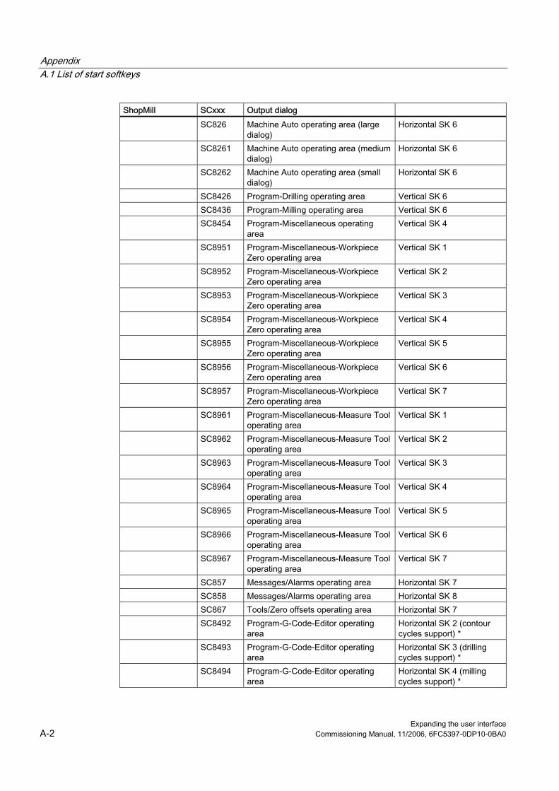
Appendix A.1 List of start softkeys
Expanding the user interface A-2 Commissioning Manual, 11/2006, 6FC5397-0DP10-0BA0
ShopMill SCxxx Output dialog SC826 Machine Auto operating area (large
dialog) Horizontal SK 6
SC8261 Machine Auto operating area (medium dialog)
Horizontal SK 6
SC8262 Machine Auto operating area (small dialog)
Horizontal SK 6
SC8426 Program-Drilling operating area Vertical SK 6 SC8436 Program-Milling operating area Vertical SK 6 SC8454 Program-Miscellaneous operating
area Vertical SK 4
SC8951 Program-Miscellaneous-Workpiece Zero operating area
Vertical SK 1
SC8952 Program-Miscellaneous-Workpiece Zero operating area
Vertical SK 2
SC8953 Program-Miscellaneous-Workpiece Zero operating area
Vertical SK 3
SC8954 Program-Miscellaneous-Workpiece Zero operating area
Vertical SK 4
SC8955 Program-Miscellaneous-Workpiece Zero operating area
Vertical SK 5
SC8956 Program-Miscellaneous-Workpiece Zero operating area
Vertical SK 6
SC8957 Program-Miscellaneous-Workpiece Zero operating area
Vertical SK 7
SC8961 Program-Miscellaneous-Measure Tool operating area
Vertical SK 1
SC8962 Program-Miscellaneous-Measure Tool operating area
Vertical SK 2
SC8963 Program-Miscellaneous-Measure Tool operating area
Vertical SK 3
SC8964 Program-Miscellaneous-Measure Tool operating area
Vertical SK 4
SC8965 Program-Miscellaneous-Measure Tool operating area
Vertical SK 5
SC8966 Program-Miscellaneous-Measure Tool operating area
Vertical SK 6
SC8967 Program-Miscellaneous-Measure Tool operating area
Vertical SK 7
SC857 Messages/Alarms operating area Horizontal SK 7 SC858 Messages/Alarms operating area Horizontal SK 8 SC867 Tools/Zero offsets operating area Horizontal SK 7 SC8492 Program-G-Code-Editor operating
area Horizontal SK 2 (contour cycles support) *
SC8493 Program-G-Code-Editor operating area
Horizontal SK 3 (drilling cycles support) *
SC8494 Program-G-Code-Editor operating area
Horizontal SK 4 (milling cycles support) *
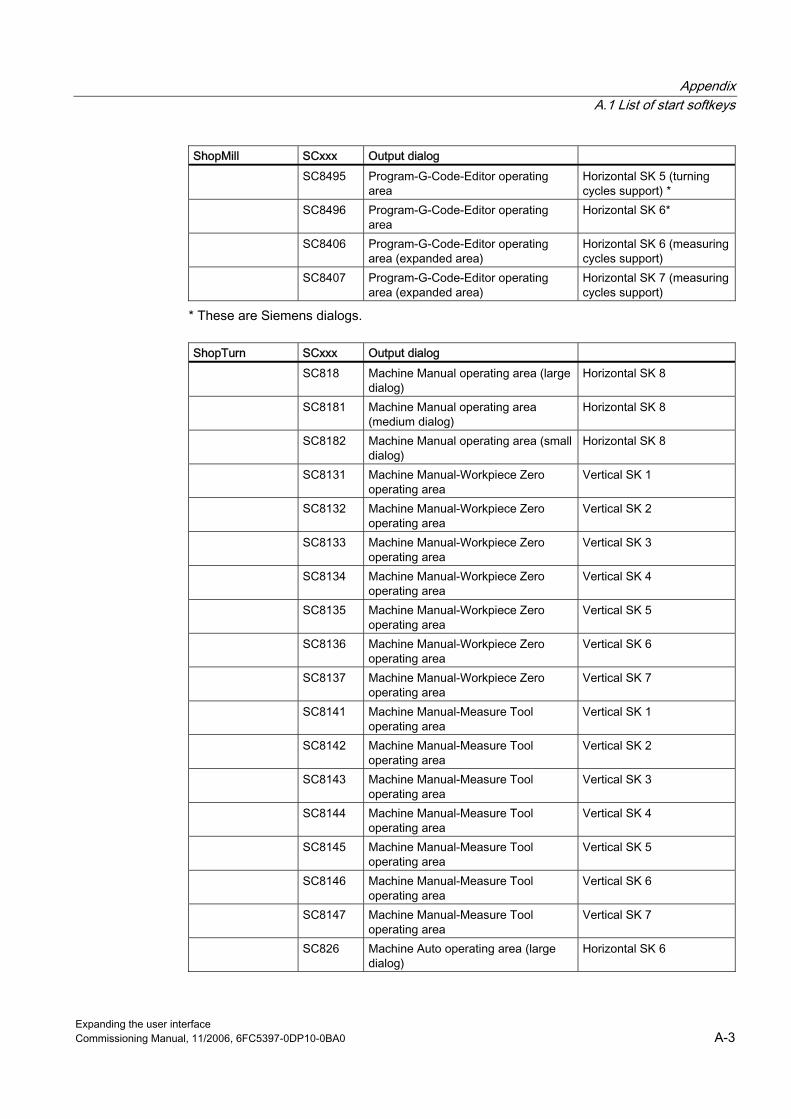
A Appendix A.1 List of start softkeys
Expanding the user interface Commissioning Manual, 11/2006, 6FC5397-0DP10-0BA0 A-3
ShopMill SCxxx Output dialog SC8495 Program-G-Code-Editor operating
area Horizontal SK 5 (turning cycles support) *
SC8496 Program-G-Code-Editor operating area
Horizontal SK 6*
SC8406 Program-G-Code-Editor operating area (expanded area)
Horizontal SK 6 (measuring cycles support)
SC8407 Program-G-Code-Editor operating area (expanded area)
Horizontal SK 7 (measuring cycles support)
* These are Siemens dialogs.
ShopTurn SCxxx Output dialog SC818 Machine Manual operating area (large
dialog) Horizontal SK 8
SC8181 Machine Manual operating area (medium dialog)
Horizontal SK 8
SC8182 Machine Manual operating area (small dialog)
Horizontal SK 8
SC8131 Machine Manual-Workpiece Zero operating area
Vertical SK 1
SC8132 Machine Manual-Workpiece Zero operating area
Vertical SK 2
SC8133 Machine Manual-Workpiece Zero operating area
Vertical SK 3
SC8134 Machine Manual-Workpiece Zero operating area
Vertical SK 4
SC8135 Machine Manual-Workpiece Zero operating area
Vertical SK 5
SC8136 Machine Manual-Workpiece Zero operating area
Vertical SK 6
SC8137 Machine Manual-Workpiece Zero operating area
Vertical SK 7
SC8141 Machine Manual-Measure Tool operating area
Vertical SK 1
SC8142 Machine Manual-Measure Tool operating area
Vertical SK 2
SC8143 Machine Manual-Measure Tool operating area
Vertical SK 3
SC8144 Machine Manual-Measure Tool operating area
Vertical SK 4
SC8145 Machine Manual-Measure Tool operating area
Vertical SK 5
SC8146 Machine Manual-Measure Tool operating area
Vertical SK 6
SC8147 Machine Manual-Measure Tool operating area
Vertical SK 7
SC826 Machine Auto operating area (large dialog)
Horizontal SK 6
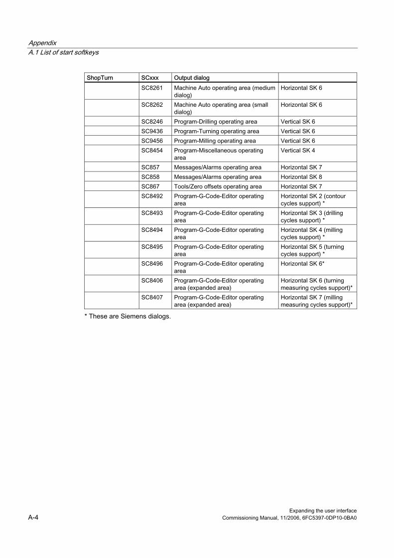
Appendix A.1 List of start softkeys
Expanding the user interface A-4 Commissioning Manual, 11/2006, 6FC5397-0DP10-0BA0
ShopTurn SCxxx Output dialog SC8261 Machine Auto operating area (medium
dialog) Horizontal SK 6
SC8262 Machine Auto operating area (small dialog)
Horizontal SK 6
SC8246 Program-Drilling operating area Vertical SK 6 SC9436 Program-Turning operating area Vertical SK 6 SC9456 Program-Milling operating area Vertical SK 6 SC8454 Program-Miscellaneous operating
area Vertical SK 4
SC857 Messages/Alarms operating area Horizontal SK 7 SC858 Messages/Alarms operating area Horizontal SK 8 SC867 Tools/Zero offsets operating area Horizontal SK 7 SC8492 Program-G-Code-Editor operating
area Horizontal SK 2 (contour cycles support) *
SC8493 Program-G-Code-Editor operating area
Horizontal SK 3 (drilling cycles support) *
SC8494 Program-G-Code-Editor operating area
Horizontal SK 4 (milling cycles support) *
SC8495 Program-G-Code-Editor operating area
Horizontal SK 5 (turning cycles support) *
SC8496 Program-G-Code-Editor operating area
Horizontal SK 6*
SC8406 Program-G-Code-Editor operating area (expanded area)
Horizontal SK 6 (turning measuring cycles support)*
SC8407 Program-G-Code-Editor operating area (expanded area)
Horizontal SK 7 (milling measuring cycles support)*
* These are Siemens dialogs.

A Appendix A.2 List of colors
Expanding the user interface Commissioning Manual, 11/2006, 6FC5397-0DP10-0BA0 A-5
A.2 A.2 List of colors
Available colors A standard color table is available for HMI Advanced and HMI Embedded sl for the purpose of configuring dialogs (subset of the respective standard colors):
Number Color 1 black 2 Red/brown 3 Dark green 4 Light gray 5 Dark gray 6 Blue 7 Red 8 brown 9 yellow 10 white
The appearance of the colors may vary slightly in each HMI program.
HMI Advanced For bitmaps in HMI Advanced, the current color table of the shipped software must be used in the character program.
HMI Embedded sl For bitmaps in HMI Embedded sl, the current color table of the shipped software must be used in the character program. Color tables depend on the "New Fashion" option. You will find the color tables in the tool box under 8x0d\examples_tools\wizard.bsp\hmi_emb\... The file names indicate the application of each table: ● HMI_EMB_NEW_FASHION.PAL:
This color palette is used for HMI Embedded sl with New Fashion. Color indices 160 to 231 are available.
● HMI_EMB_OLD_AND_NEW_FASHION.PAL: This color palette is used for HMI Embedded sl with both Old and New Fashion; the bitmaps generated with this color palette are identical in appearance for Old and New Fashion. Color indices 160, 163, 184, 187, 196, 199, 204, 205, 207, 217, 219, 220, 221, 223, 226 and 228 are available
The previous color table HMI_EMB.PAL is superseded by the tables specified above. Only colors 160 through 231 can be used. This is the only way to ensure that images look the same on HMI Embedded sl and HMI Advanced.

Appendix A.2 List of colors
Expanding the user interface A-6 Commissioning Manual, 11/2006, 6FC5397-0DP10-0BA0
Activating a color table in Paint Shop Pro: ● File → Open → ...\*.bmp ● Colors → Open picture palette → ...\*.PAL ● Apply palette by selecting the "Color Indices: Open" option.
System colors There is a choice of 10 colors available for the color of an element (text, input field, background, etc.). The system colors have been expanded and there is a difference between the old and new designs (e. g., the header color). In order to achieve a demarcation between unique and design-dependent colors, it has been defined that the unique colors are found between 0 and 128. The design-dependent colors that have been newly introduced as part of this expansion, are defined from index 128. This means, that also when the unique colors are expanded (up to 128), it is prevented that both color types are mixed.
Newly defined colors
Color Index Color description Old design New design
128 System color active field yellow orange 129 Background color Gray Light gray 130 Header color (active) yellow Blue 131 Header font color (active) black white

A Appendix A.3 List of accessible system variables
Expanding the user interface Commissioning Manual, 11/2006, 6FC5397-0DP10-0BA0 A-7
A.3 A.3 List of accessible system variables Name Index Description $A_DBB[x] x=ByteNo Data byte from/to PLC $A_DBD[x] x=Offset Double data word (32bit) from/to PLC $A_DBR[x] x=Offset Real data (32 bit) from/to PLC $A_DBW[x] x=Offset Data word (16 bit) from/to PLC $A_DLB[index] index=Offset Data byte in link area $A_DLD[index] index=Offset Data access to double word in link area $A_DLR[index] index=Offset Real data in link area $A_DLW[index] index=Offset Data word in link area $A_IN[x] x=DigitalinputNo Value of HW digital input $A_INA[x] x=AnaloginputNo Value of HW analog input $A_INCO[x] x=InputNo Comparator input NC $A_INSE Safe Programmable Logic:
External input of the NCK I/O $A_INSED Safe Programmable Logic:
Image of external NCK input $A_INSEP Safe Programmable Logic:
External input of the PLC I/O $A_INSEPD Safe Programmable Logic:
Image of external PLC inputs $A_INSI Safe Programmable Logic:
Internal NCK input safety $A_INSID Safe Programmable Logic:
Image of internal NCK input safety $A_INSIP Safe Programmable Logic:
Internal PLC input safety $A_LINK_TRANS_RATE Link transfer rate $A_MARKERSI Safe Programmable Logic: NCK markers $A_MARKERSIP Safe Programmable Logic:
Image of PLC markers $A_OUT[x] x=DigitaloutputNo Value of HW digital output $A_OUTA[x] x=AnalogoutputNo Value of HW analog output $A_OUTSE Safe Programmable Logic:
External output of the NCK I/O $A_OUTSED Safe Programmable Logic:
Image of external NCK output $A_OUTSEP Safe Programmable Logic:
External output of the PLC I/O $A_OUTSEPD Safe Programmable Logic:
Image of the external PLC output
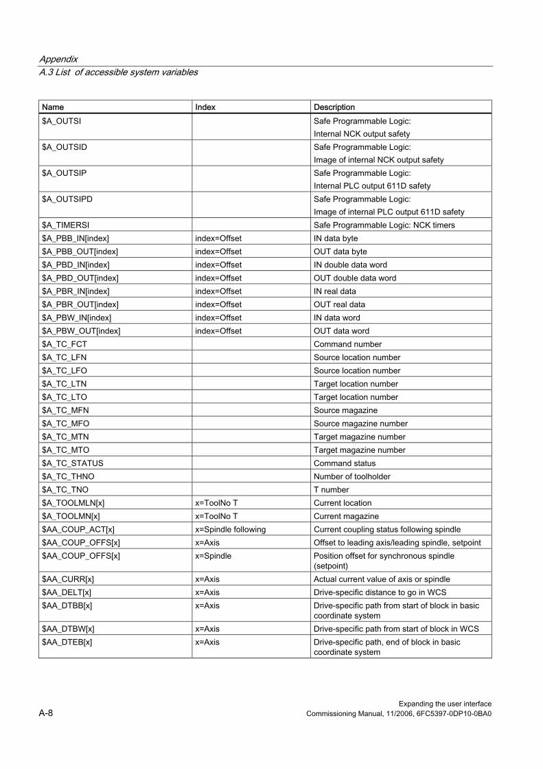
Appendix A.3 List of accessible system variables
Expanding the user interface A-8 Commissioning Manual, 11/2006, 6FC5397-0DP10-0BA0
Name Index Description $A_OUTSI Safe Programmable Logic:
Internal NCK output safety $A_OUTSID Safe Programmable Logic:
Image of internal NCK output safety $A_OUTSIP Safe Programmable Logic:
Internal PLC output 611D safety $A_OUTSIPD Safe Programmable Logic:
Image of internal PLC output 611D safety $A_TIMERSI Safe Programmable Logic: NCK timers $A_PBB_IN[index] index=Offset IN data byte $A_PBB_OUT[index] index=Offset OUT data byte $A_PBD_IN[index] index=Offset IN double data word $A_PBD_OUT[index] index=Offset OUT double data word $A_PBR_IN[index] index=Offset IN real data $A_PBR_OUT[index] index=Offset OUT real data $A_PBW_IN[index] index=Offset IN data word $A_PBW_OUT[index] index=Offset OUT data word $A_TC_FCT Command number $A_TC_LFN Source location number $A_TC_LFO Source location number $A_TC_LTN Target location number $A_TC_LTO Target location number $A_TC_MFN Source magazine $A_TC_MFO Source magazine number $A_TC_MTN Target magazine number $A_TC_MTO Target magazine number $A_TC_STATUS Command status $A_TC_THNO Number of toolholder $A_TC_TNO T number $A_TOOLMLN[x] x=ToolNo T Current location $A_TOOLMN[x] x=ToolNo T Current magazine $AA_COUP_ACT[x] x=Spindle following Current coupling status following spindle $AA_COUP_OFFS[x] x=Axis Offset to leading axis/leading spindle, setpoint $AA_COUP_OFFS[x] x=Spindle Position offset for synchronous spindle
(setpoint) $AA_CURR[x] x=Axis Actual current value of axis or spindle $AA_DELT[x] x=Axis Drive-specific distance to go in WCS $AA_DTBB[x] x=Axis Drive-specific path from start of block in basic
coordinate system $AA_DTBW[x] x=Axis Drive-specific path from start of block in WCS $AA_DTEB[x] x=Axis Drive-specific path, end of block in basic
coordinate system
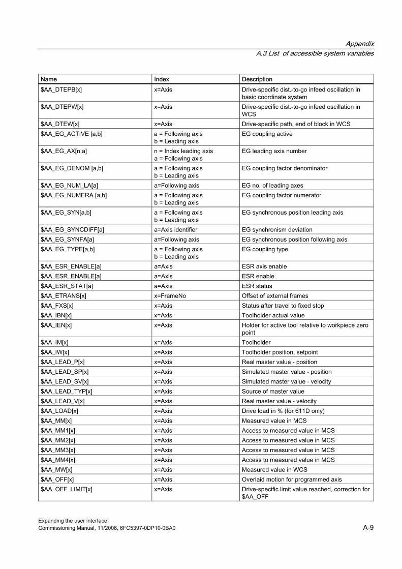
A Appendix A.3 List of accessible system variables
Expanding the user interface Commissioning Manual, 11/2006, 6FC5397-0DP10-0BA0 A-9
Name Index Description $AA_DTEPB[x] x=Axis Drive-specific dist.-to-go infeed oscillation in
basic coordinate system $AA_DTEPW[x] x=Axis Drive-specific dist.-to-go infeed oscillation in
WCS $AA_DTEW[x] x=Axis Drive-specific path, end of block in WCS $AA_EG_ACTIVE [a,b] a = Following axis
b = Leading axis EG coupling active
$AA_EG_AX[n,a] n = Index leading axis a = Following axis
EG leading axis number
$AA_EG_DENOM [a,b] a = Following axis b = Leading axis
EG coupling factor denominator
$AA_EG_NUM_LA[a] a=Following axis EG no. of leading axes $AA_EG_NUMERA [a,b] a = Following axis
b = Leading axis EG coupling factor numerator
$AA_EG_SYN[a,b] a = Following axis b = Leading axis
EG synchronous position leading axis
$AA_EG_SYNCDIFF[a] a=Axis identifier EG synchronism deviation $AA_EG_SYNFA[a] a=Following axis EG synchronous position following axis $AA_EG_TYPE[a,b] a = Following axis
b = Leading axis EG coupling type
$AA_ESR_ENABLE[a] a=Axis ESR axis enable $AA_ESR_ENABLE[a] a=Axis ESR enable $AA_ESR_STAT[a] a=Axis ESR status $AA_ETRANS[x] x=FrameNo Offset of external frames $AA_FXS[x] x=Axis Status after travel to fixed stop $AA_IBN[x] x=Axis Toolholder actual value $AA_IEN[x] x=Axis Holder for active tool relative to workpiece zero
point $AA_IM[x] x=Axis Toolholder $AA_IW[x] x=Axis Toolholder position, setpoint $AA_LEAD_P[x] x=Axis Real master value - position $AA_LEAD_SP[x] x=Axis Simulated master value - position $AA_LEAD_SV[x] x=Axis Simulated master value - velocity $AA_LEAD_TYP[x] x=Axis Source of master value $AA_LEAD_V[x] x=Axis Real master value - velocity $AA_LOAD[x] x=Axis Drive load in % (for 611D only) $AA_MM[x] x=Axis Measured value in MCS $AA_MM1[x] x=Axis Access to measured value in MCS $AA_MM2[x] x=Axis Access to measured value in MCS $AA_MM3[x] x=Axis Access to measured value in MCS $AA_MM4[x] x=Axis Access to measured value in MCS $AA_MW[x] x=Axis Measured value in WCS $AA_OFF[x] x=Axis Overlaid motion for programmed axis $AA_OFF_LIMIT[x] x=Axis Drive-specific limit value reached, correction for
$AA_OFF

Appendix A.3 List of accessible system variables
Expanding the user interface A-10 Commissioning Manual, 11/2006, 6FC5397-0DP10-0BA0
Name Index Description $AA_OSCILL_REVERSE_POS1[x] x=Axis Current reversal position 1 oscill. in
synchronous actions $AA_OSCILL_REVERSE_POS2[x] x=Axis Current reversal position 2 oscill. in
synchronous actions $AA_OVR[x] x=Axis Drive-specific override for motion-synchronous
actions $AA_POWER[x] x=Axis Drive active power in [Watts] $AA_S[x] x=SpindleNo Spindle speed, setpoint $AA_SOFTENDN[x] x=Axis Software limit position, negative direction $AA_SOFTENDP[x] x=Axis Software limit position, positive direction $AA_STAT[x] x=Axis Axis status $AA_SYNA_MEM Free memory space, motion synchronous
actions $AA_SYNC[x] x=Axis Coupling of the slave axis for master value
coupling $AA_TORQUE[x] x=Axis Drive torque setpoint in [Nm] $AA_TYP[x] x=Axis Axis type $AA_VACTB[x] x=Axis Drive-specific feed, actual value $AA_VACTM[x] x=Axis Drive-specific feed, setpoint $AA_VACTW[x] x=Axis Drive-specific feed, actual value $AA_VC[x] x=Axis Drive-specific feed,
additive path feed correction $AC_ALARM_STAT ESR alarm status $AC_AXCTSWA[CTn] CTn=Axis container no. Axis container status $AC_DELT Distance to go, path WCS $AC_DRF[x] x=Axis DRF value $AC_DTBB Distance from start of block in basic coordinate
system $AC_DTBW Distance from block start in WCS $AC_DTEB Distance from end of block in basic coordinate
system $AC_DTEPB Distance to go for oscillating infeed of basic
coordinate system $AC_DTEPW Distance to go for oscillating infeed in WCS $AC_DTEW Distance from block end in WCS $AC_FCT0[x] x=PolynomNo a0 coefficient nth polynomial for synchr. action $AC_FCT1[x] x=PolynomNo a1 coefficient nth polynomial for synchr. action $AC_FCT2[x] x=PolynomNo a2 coefficient nth polynomial for synchr. action $AC_FCT3[x] x=PolynomNo a3 coefficient nth polynomial for synchr. action $AC_FCTLL[x] x=PolynomNo Lower limit value nth polynomial for
synchronized action $AC_FCTUL[x] x=PolynomNo Upper limit value nth polynomial for
synchronized action $AC_FIFOx[y] x=FIFONo (1-10)
y=ParameterNo FIFO variables for synchronous actions

A Appendix A.3 List of accessible system variables
Expanding the user interface Commissioning Manual, 11/2006, 6FC5397-0DP10-0BA0 A-11
Name Index Description $AC_MARKER[x] x=MarkerNo Counter for motion synchronous actions $AC_MEA Probe has responded $AC_OVR Path override for synchronous actions $AC_PARAM[x] x=ParameterNo Dyn. parameter for motion synchronization $AC_PATHN Normalized path parameter $AC_PLTBB Distance from start of block in basic coordinate
system $AC_PLTEB Distance from block end in basic coordinate
system $AC_PRESET[x] x=Axis PRESET value $AC_PROG Program status $AC_RETPOINT[x] x=Axis Return position on contour for repositioning $AC_SDIR[x] x=SpindleNo Rotat. status $AC_SMODE[x] x=SpindleNo Spindle mode $AC_STAT Channel status $AC_TIME Time from the start of the block in seconds
(including the times for the internally generated intermediate blocks)
$AC_TIMES Time from the start of the block in seconds (without times for the internally generated intermediate blocks)
$AC_TIMEC Time from the start of the block in interpolation clock cycles (including clock cycles for the internally generated intermediate blocks)
$AC_TIMESC Time from the start of the block in interpolation clock cycles (without the clock cycles for internally generated intermediate blocks)
$AC_TIMER[x] x=TimerNo Timer location in seconds $AC_VACTB Interpolation feedrate, setpoint $AC_VACTW Path velocity in WCS $AC_VC Additive path feed correction for synchronous
actions $AN_AXCTAS[n] Actual axis container address (rotary position) $AN_AXCTSWA[CTn] CTn=Axis container no. Axis container rotation active $AN_ESR_TRIGGER ESR start signal $AN_MARKER[x] x=MarkerNo Marker variable for motion synchronous actions $MC_DISPLAY_AXIS Bits 16 -31 Machine axis identifier $MC_DISPLAY_AXIS Bits 0 -15 Identifier for geometry/auxiliary axis $MC_MM_NUM_BASE_FRAMES Number of base frames in channel $MN_EXTERN_LANGUAGE $MN_EXTERN_CNC_SYSTEM
and CNC system language
$MN_MAX_CUTTING_EDGE_NO Max. value D number $MN_MAX_CUTTING_EDGE_ PER_TOOL
Max. number of edges per tool

Appendix A.3 List of accessible system variables
Expanding the user interface A-12 Commissioning Manual, 11/2006, 6FC5397-0DP10-0BA0
Name Index Description $MN_MAX_SUMCORR_ PERCUTTING_EDGE
Max. number of total offsets per cutting edge
$MN_MM_KIND_OF_SUMCORR Properties of total offsets in NCK $MN_MM_NUM_CC_MAGAZINE_ PARAM
Number of parameters for one tool magazine
$MN_MM_NUM_CC_MAGLOC_ PARAM
Number of parameters for one tool magazine location
$MN_MM_NUM_CC_MON_ PARAM Number of parameters of monitoring user data of one tool edge
$MN_MM_NUM_GLOBAL_BASE_ FRAMES
Number of channel-dependent basic frames
$MN_MM_NUM_SUMCORR Total number of total offsets in NCK $MN_MM_NUM_TOOL_ADAPTER Max. number of traversed tool adapter data
blocks $MN_MM_TOOL_MANAGEMENT_ MASK
Settings NCK tool management
$P_UBFR[ x ,MI] x=FrameNo Mirroring of settable frame $P_UBFR[x,RT] x=FrameNo Rotation of settable frame $P_UBFR[x,SC] x=FrameNo Scaling factor of settable frame $P_UBFR[x,SI] x=FrameNo Fine offset for frames $P_UBFR[x,TR] x=FrameNo Translation of settable frame $P_CHBFRMASK Active channel-specific basic frames $P_EG_BC[a] EG block change criterion $P_NCBFRMASK Active channel-independent basic frames $P_OFFN Offset normal $P_PFRAME[x,TR] $P_ACTFRAME $P_IFRAME
or or
Compilation of active frame
$P_TOOL Number of active tool edge $P_TOOLL[1] Active tool length 1 $P_TOOLL[2] Active tool length 2 $P_TOOLL[3] Active tool length 3 $P_TOOLND[x] x=ToolNo Number of cutting edges $P_TOOLNO Number of active tool $P_TOOLR Active tool radius $P_UIFR[x,y,MI] x=FrameNo, y=Axis Mirroring of settable frame $P_UIFR[x,y,RT] x=FrameNo, y=Axis Rotation of settable frame $P_UIFR[x,y,SC] x=FrameNo, y=Axis Scaling factor of settable frame $P_UIFR[x,y,SI] x=FrameNo, y=Axis Fine offset for frames $P_UIFR[x,y,TR] x=FrameNo, y=Axis Translation of settable frame $P_UIFRNUM Index of active set frame $R[x] x=ParameterNo R parameters $SC_PA_ACTIV_IMMED[x] x=Number protection zone Immediately active after referencing $SC_PA_CENT_ABS[x,0] x=Number protection zone Abscissa of arc center of 1st contour element
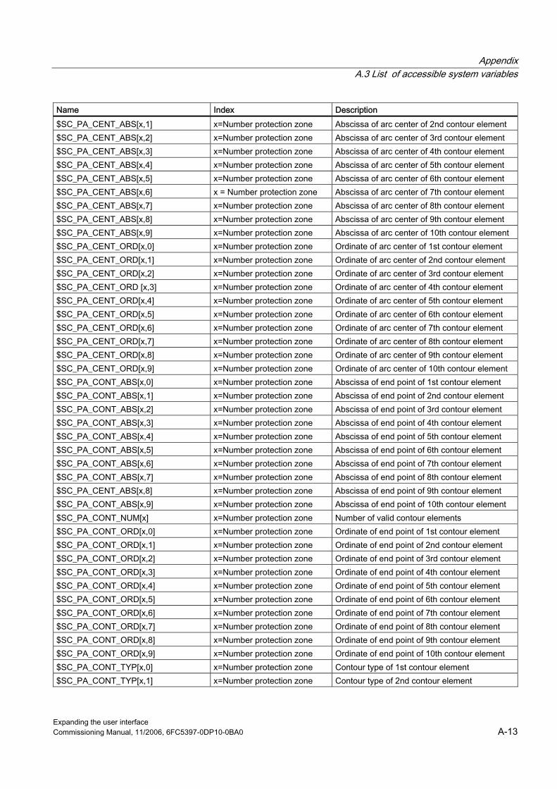
A Appendix A.3 List of accessible system variables
Expanding the user interface Commissioning Manual, 11/2006, 6FC5397-0DP10-0BA0 A-13
Name Index Description $SC_PA_CENT_ABS[x,1] x=Number protection zone Abscissa of arc center of 2nd contour element $SC_PA_CENT_ABS[x,2] x=Number protection zone Abscissa of arc center of 3rd contour element $SC_PA_CENT_ABS[x,3] x=Number protection zone Abscissa of arc center of 4th contour element $SC_PA_CENT_ABS[x,4] x=Number protection zone Abscissa of arc center of 5th contour element $SC_PA_CENT_ABS[x,5] x=Number protection zone Abscissa of arc center of 6th contour element $SC_PA_CENT_ABS[x,6] x = Number protection zone Abscissa of arc center of 7th contour element $SC_PA_CENT_ABS[x,7] x=Number protection zone Abscissa of arc center of 8th contour element $SC_PA_CENT_ABS[x,8] x=Number protection zone Abscissa of arc center of 9th contour element $SC_PA_CENT_ABS[x,9] x=Number protection zone Abscissa of arc center of 10th contour element $SC_PA_CENT_ORD[x,0] x=Number protection zone Ordinate of arc center of 1st contour element $SC_PA_CENT_ORD[x,1] x=Number protection zone Ordinate of arc center of 2nd contour element $SC_PA_CENT_ORD[x,2] x=Number protection zone Ordinate of arc center of 3rd contour element $SC_PA_CENT_ORD [x,3] x=Number protection zone Ordinate of arc center of 4th contour element $SC_PA_CENT_ORD[x,4] x=Number protection zone Ordinate of arc center of 5th contour element $SC_PA_CENT_ORD[x,5] x=Number protection zone Ordinate of arc center of 6th contour element $SC_PA_CENT_ORD[x,6] x=Number protection zone Ordinate of arc center of 7th contour element $SC_PA_CENT_ORD[x,7] x=Number protection zone Ordinate of arc center of 8th contour element $SC_PA_CENT_ORD[x,8] x=Number protection zone Ordinate of arc center of 9th contour element $SC_PA_CENT_ORD[x,9] x=Number protection zone Ordinate of arc center of 10th contour element $SC_PA_CONT_ABS[x,0] x=Number protection zone Abscissa of end point of 1st contour element $SC_PA_CONT_ABS[x,1] x=Number protection zone Abscissa of end point of 2nd contour element $SC_PA_CONT_ABS[x,2] x=Number protection zone Abscissa of end point of 3rd contour element $SC_PA_CONT_ABS[x,3] x=Number protection zone Abscissa of end point of 4th contour element $SC_PA_CONT_ABS[x,4] x=Number protection zone Abscissa of end point of 5th contour element $SC_PA_CONT_ABS[x,5] x=Number protection zone Abscissa of end point of 6th contour element $SC_PA_CONT_ABS[x,6] x=Number protection zone Abscissa of end point of 7th contour element $SC_PA_CONT_ABS[x,7] x=Number protection zone Abscissa of end point of 8th contour element $SC_PA_CENT_ABS[x,8] x=Number protection zone Abscissa of end point of 9th contour element $SC_PA_CONT_ABS[x,9] x=Number protection zone Abscissa of end point of 10th contour element $SC_PA_CONT_NUM[x] x=Number protection zone Number of valid contour elements $SC_PA_CONT_ORD[x,0] x=Number protection zone Ordinate of end point of 1st contour element $SC_PA_CONT_ORD[x,1] x=Number protection zone Ordinate of end point of 2nd contour element $SC_PA_CONT_ORD[x,2] x=Number protection zone Ordinate of end point of 3rd contour element $SC_PA_CONT_ORD[x,3] x=Number protection zone Ordinate of end point of 4th contour element $SC_PA_CONT_ORD[x,4] x=Number protection zone Ordinate of end point of 5th contour element $SC_PA_CONT_ORD[x,5] x=Number protection zone Ordinate of end point of 6th contour element $SC_PA_CONT_ORD[x,6] x=Number protection zone Ordinate of end point of 7th contour element $SC_PA_CONT_ORD[x,7] x=Number protection zone Ordinate of end point of 8th contour element $SC_PA_CONT_ORD[x,8] x=Number protection zone Ordinate of end point of 9th contour element $SC_PA_CONT_ORD[x,9] x=Number protection zone Ordinate of end point of 10th contour element $SC_PA_CONT_TYP[x,0] x=Number protection zone Contour type of 1st contour element $SC_PA_CONT_TYP[x,1] x=Number protection zone Contour type of 2nd contour element
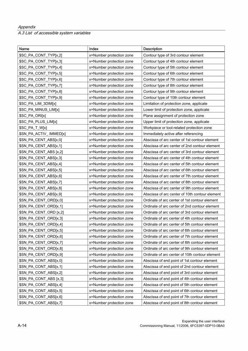
Appendix A.3 List of accessible system variables
Expanding the user interface A-14 Commissioning Manual, 11/2006, 6FC5397-0DP10-0BA0
Name Index Description $SC_PA_CONT_TYP[x,2] x=Number protection zone Contour type of 3rd contour element $SC_PA_CONT_TYP[x,3] x=Number protection zone Contour type of 4th contour element $SC_PA_CONT_TYP[x,4] x=Number protection zone Contour type of 5th contour element $SC_PA_CONT_TYP[x,5] x=Number protection zone Contour type of 6th contour element $SC_PA_CONT_TYP[x,6] x=Number protection zone Contour type of 7th contour element $SC_PA_CONT_TYP[x,7] x=Number protection zone Contour type of 8th contour element $SC_PA_CONT_TYP[x,8] x=Number protection zone Contour type of 9th contour element $SC_PA_CONT_TYP[x,9] x=Number protection zone Contour type of 10th contour element $SC_PA_LIM_3DIM[x] x=Number protection zone Limitation of protection zone, applicate $SC_PA_MINUS_LIM[x] x=Number protection zone Lower limit of protection zone, applicate $SC_PA_ORI[x] x=Number protection zone Plane assignment of protection zone $SC_PA_PLUS_LIM[x] x=Number protection zone Upper limit of protection zone, applicate $SC_PA_T_W[x] x=Number protection zone Workpiece or tool-related protection zone $SN_PA_ACTIV_ IMMED[x] x=Number protection zone Immediately active after referencing $SN_PA_CENT_ABS[x,0] x=Number protection zone Abscissa of arc center of 1st contour element $SN_PA_CENT_ABS[x,1] x=Number protection zone Abscissa of arc center of 2nd contour element $SN_PA_CENT_ABS [x,2] x=Number protection zone Abscissa of arc center of 3rd contour element $SN_PA_CENT_ABS[x,3] x=Number protection zone Abscissa of arc center of 4th contour element $SN_PA_CENT_ABS[x,4] x=Number protection zone Abscissa of arc center of 5th contour element $SN_PA_CENT_ABS[x,5] x=Number protection zone Abscissa of arc center of 6th contour element $SN_PA_CENT_ABS[x,6] x=Number protection zone Abscissa of arc center of 7th contour element $SN_PA_CENT_ABS[x,7] x=Number protection zone Abscissa of arc center of 8th contour element $SN_PA_CENT_ABS[x,8] x=Number protection zone Abscissa of arc center of 9th contour element $SN_PA_CENT_ABS[x,9] x=Number protection zone Abscissa of arc center of 10th contour element $SN_PA_CENT_ORD[x,0] x=Number protection zone Ordinate of arc center of 1st contour element $SN_PA_CENT_ORD[x,1] x=Number protection zone Ordinate of arc center of 2nd contour element $SN_PA_CENT_ORD [x,2] x=Number protection zone Ordinate of arc center of 3rd contour element $SN_PA_CENT_ORD[x,3] x=Number protection zone Ordinate of arc center of 4th contour element $SN_PA_CENT_ORD[x,4] x=Number protection zone Ordinate of arc center of 5th contour element $SN_PA_CENT_ORD[x,5] x=Number protection zone Ordinate of arc center of 6th contour element $SN_PA_CENT_ORD[x,6] x=Number protection zone Ordinate of arc center of 7th contour element $SN_PA_CENT_ORD[x,7] x=Number protection zone Ordinate of arc center of 8th contour element $SN_PA_CENT_ORD[x,8] x=Number protection zone Ordinate of arc center of 9th contour element $SN_PA_CENT_ORD[x,9] x=Number protection zone Ordinate of arc center of 10th contour element $SN_PA_CONT_ABS[x,0] x=Number protection zone Abscissa of end point of 1st contour element $SN_PA_CONT_ABS[x,1] x=Number protection zone Abscissa of end point of 2nd contour element $SN_PA_CONT_ABS[x,2] x=Number protection zone Abscissa of end point of 3rd contour element $SN_PA_CONT_ABS [x,3] x=Number protection zone Abscissa of end point of 4th contour element $SN_PA_CONT_ABS[x,4] x=Number protection zone Abscissa of end point of 5th contour element $SN_PA_CONT_ABS[x,5] x=Number protection zone Abscissa of end point of 6th contour element $SN_PA_CONT_ABS[x,6] x=Number protection zone Abscissa of end point of 7th contour element $SN_PA_CONT_ABS[x,7] x=Number protection zone Abscissa of end point of 8th contour element
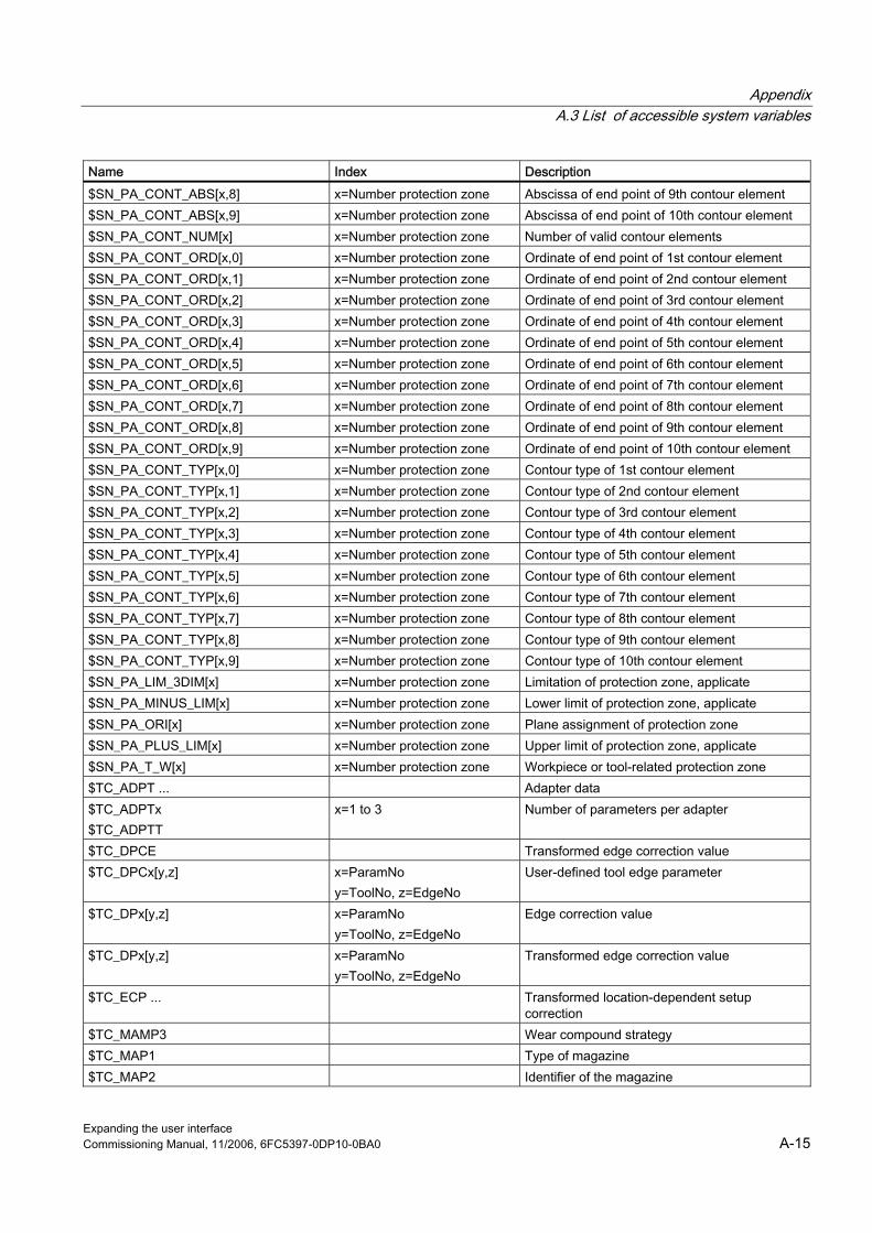
A Appendix A.3 List of accessible system variables
Expanding the user interface Commissioning Manual, 11/2006, 6FC5397-0DP10-0BA0 A-15
Name Index Description $SN_PA_CONT_ABS[x,8] x=Number protection zone Abscissa of end point of 9th contour element $SN_PA_CONT_ABS[x,9] x=Number protection zone Abscissa of end point of 10th contour element $SN_PA_CONT_NUM[x] x=Number protection zone Number of valid contour elements $SN_PA_CONT_ORD[x,0] x=Number protection zone Ordinate of end point of 1st contour element $SN_PA_CONT_ORD[x,1] x=Number protection zone Ordinate of end point of 2nd contour element $SN_PA_CONT_ORD[x,2] x=Number protection zone Ordinate of end point of 3rd contour element $SN_PA_CONT_ORD[x,3] x=Number protection zone Ordinate of end point of 4th contour element $SN_PA_CONT_ORD[x,4] x=Number protection zone Ordinate of end point of 5th contour element $SN_PA_CONT_ORD[x,5] x=Number protection zone Ordinate of end point of 6th contour element $SN_PA_CONT_ORD[x,6] x=Number protection zone Ordinate of end point of 7th contour element $SN_PA_CONT_ORD[x,7] x=Number protection zone Ordinate of end point of 8th contour element $SN_PA_CONT_ORD[x,8] x=Number protection zone Ordinate of end point of 9th contour element $SN_PA_CONT_ORD[x,9] x=Number protection zone Ordinate of end point of 10th contour element $SN_PA_CONT_TYP[x,0] x=Number protection zone Contour type of 1st contour element $SN_PA_CONT_TYP[x,1] x=Number protection zone Contour type of 2nd contour element $SN_PA_CONT_TYP[x,2] x=Number protection zone Contour type of 3rd contour element $SN_PA_CONT_TYP[x,3] x=Number protection zone Contour type of 4th contour element $SN_PA_CONT_TYP[x,4] x=Number protection zone Contour type of 5th contour element $SN_PA_CONT_TYP[x,5] x=Number protection zone Contour type of 6th contour element $SN_PA_CONT_TYP[x,6] x=Number protection zone Contour type of 7th contour element $SN_PA_CONT_TYP[x,7] x=Number protection zone Contour type of 8th contour element $SN_PA_CONT_TYP[x,8] x=Number protection zone Contour type of 9th contour element $SN_PA_CONT_TYP[x,9] x=Number protection zone Contour type of 10th contour element $SN_PA_LIM_3DIM[x] x=Number protection zone Limitation of protection zone, applicate $SN_PA_MINUS_LIM[x] x=Number protection zone Lower limit of protection zone, applicate $SN_PA_ORI[x] x=Number protection zone Plane assignment of protection zone $SN_PA_PLUS_LIM[x] x=Number protection zone Upper limit of protection zone, applicate $SN_PA_T_W[x] x=Number protection zone Workpiece or tool-related protection zone $TC_ADPT ... Adapter data $TC_ADPTx $TC_ADPTT
x=1 to 3 Number of parameters per adapter
$TC_DPCE Transformed edge correction value $TC_DPCx[y,z] x=ParamNo
y=ToolNo, z=EdgeNo User-defined tool edge parameter
$TC_DPx[y,z] x=ParamNo y=ToolNo, z=EdgeNo
Edge correction value
$TC_DPx[y,z] x=ParamNo y=ToolNo, z=EdgeNo
Transformed edge correction value
$TC_ECP ... Transformed location-dependent setup correction
$TC_MAMP3 Wear compound strategy $TC_MAP1 Type of magazine $TC_MAP2 Identifier of the magazine

Appendix A.3 List of accessible system variables
Expanding the user interface A-16 Commissioning Manual, 11/2006, 6FC5397-0DP10-0BA0
Name Index Description $TC_MAP3 Status of magazine $TC_MAP4 Link 1 between magazine and next magazine $TC_MAP5 Link 2 between magazine and preceding
magazine $TC_MAP6 Magazine dimension $TC_MAP9 Number of active wear group $TC_MAPCx[y] x=ParameterNo
y=MagazineNo Magazine user data for a tool magazine
$TC_MOP1(x,y) … $TC_MOP15(x,y) x=ToolNo y=EdgeNo
Monitoring data for each tool edge
$TC_MOPCx[y,z] x=ParamNo, y=T number z=Edge
Magazine user data for a tool edge
$TC_MPPCx[y,z] x= ParamNo y= MagazineNo z= MagPlaceNo
Magazine location user data for a tool magazine
$TC_MPPx x=1,...7 No. of parameters per magazine location $TC_SCP... Transformed location-dependent wear
correction $TC_SCP... Location-dependent wear correction $TC_SCPx x=13,...21,....71 Number of total offset parameters per total
offset block $TC_TP1 DUPLO number $TC_TP10 Tool search type for replacement tools $TC_TP11 Tool information for HMI $TC_TP2 Tool designation $TC_TP3 Size to left in half locations $TC_TP4 Size to right in half locations $TC_TP5 Size upwards in half locations $TC_TP6 Size downwards in half locations $TC_TP7 Magazine location type $TC_TP8 Tool status $TC_TP9 Tool monitoring method $TC_TPCx[y] x=ParameterNo
y = ToolNo User-defined tool parameter
$TC_TPG1 Spindle number $TC_TPG2 Chaining rule $TC_TPG3 Minimum wheel diameter $TC_TPG4 Minimum grinding wheel width $TC_TPG5 Current width of grinding wheel $TC_TPG6 Maximum speed of grinding wheel $TC_TPG7 Maximum peripheral speed of grinding wheel
(SUG) $TC_TPG8 Angle of inclination of inclined grinding wheel

A Appendix A.4 List of Pl services
Expanding the user interface Commissioning Manual, 11/2006, 6FC5397-0DP10-0BA0 A-17
Name Index Description $TC_TPG9 Compensation parameter for GWPS $VA_COUP_OFFS[x] x=Axis Offset to leading axis / leading spindle, actual
value $VA_IS[x] x=Axis Safe actual position of axis $VA_VACTM[x] x=Axis Actual-value, load-end axis velocity in MCS
system
A.4 A.4 List of Pl services
Programming
Syntax PI_SERVICE(service, n parameters) Service PI service identifier n parameters List of PI service parameters.
Individual parameters are separated by commas.
Service Explanation Parameter Example _N_ASUP_ An interrupt number in the specified channel is assigned to a parts program stored
in the NCK (identified by path name and program name). This PI service is identical to program instruction 'SETINT'.
Par1 Interrupt number (0 – 8) Par2 Priority (0 – 8) Par3 Liftfast (0, 1) Par4 Block synchronization (0, 1) Par5 Path data with max. 32 positions
Assignment of interrupt 5 to program MPF_DIR/TEST_MPF in the current channel. The interrupt has priority 3 and is executed without rapid lift on the PI_SERVICE("_N_ASUP__",5, 3, 0, 0,"/_N_MPF_DIR/_N_TEST_MPF")
_N_CANCEL All alarms with the "Cancel Alarm" classification can be acknowledged with this command. Individual acknowledgment for specific alarms is not possible.
--- All alarms with the "Cancel Alarm" classification are reset.
PI_SERVICE("_N_CANCEL“)

Appendix A.4 List of Pl services
Expanding the user interface A-18 Commissioning Manual, 11/2006, 6FC5397-0DP10-0BA0
Service Explanation Parameter Example _N_CRCEDN Create tool edge by specifying the cutting edge number. If the T number of an
existing tool is entered in parameter "T Number" of this service, then a tool edge for the existing tool is created (in this case, the parameter "D number", i.e., the number of the edge to be created, has a value range of 1-9). If a positive T number is specified as a parameter and the tool for the T number entered does not exist, then the PI service is aborted. If a value of 0 is entered as the T number (model of absolute D numbers), then the D number values can range from 1 – 31999. The new cutting edge is set up with the specified D number. If the specified cutting edge already exists, then the PI service is aborted in both cases.
Par1 T number Par2 D number T number == 0 ==> 1 – 3199 T number > 0 ==> 1 – 9
A tool edge with number 3 is created for the tool with number 17 in the current TO area. PI_SERVICE("_N_CRCEDN",17,3)
_N_CREACE Create a new tool edge for a specified tool. The next-higher available D number is automatically set up. The following blocks in the active file system are affected by this PI service: Tool offsets TO: The relevant tool edge (with ZERO content) is set up Monitoring data TS: (If available) the relevant tool edge (with ZERO content) is set up User edge data TUE: (If available) the relevant tool edge (with ZERO content) is set up (SW releases NCK < 10.x)
Par1 Tool number 1 to 31999 After the tool with number 55 has been set up in T area 1, a further 2 edges are
created for it. The tool therefore now possesses a total of 3 edges. PI_SERVICE("_N_CREATO",55) PI_SERVICE("_N_CREACE",55) PI_SERVICE("_N_CREACE",55)
_N_CREATO Create a tool with a specific T number. The following blocks in the active file system are affected by this PI service: Tool directory TV: The tool is entered as an existing tool. Tool offsets TO: The first tool edge D1 (with ZERO content) is set up. User edge data TUE: (If available) the first tool edge D1 (with ZERO content) is set up. User tool data TU: (If available) an empty data block is made available for the tool.
Par1 Tool number 1 to 31999 After the tool with number 55 has been set up in T area 1, a further 2 edges are
created for it. The tool therefore now possesses a total of 3 edges. PI_SERVICE("_N_CREATO",55) PI_SERVICE("_N_CREACE",55) PI_SERVICE("_N_CREACE",55)
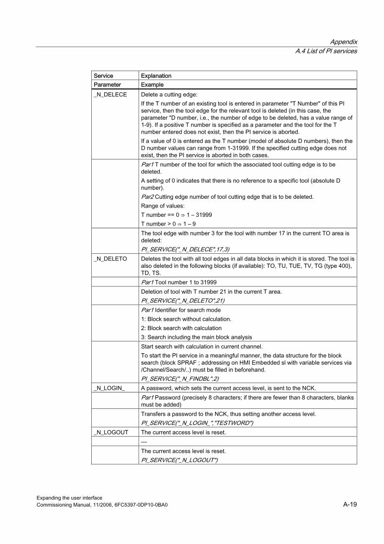
A Appendix A.4 List of Pl services
Expanding the user interface Commissioning Manual, 11/2006, 6FC5397-0DP10-0BA0 A-19
Service Explanation Parameter Example _N_DELECE Delete a cutting edge:
If the T number of an existing tool is entered in parameter "T Number" of this PI service, then the tool edge for the relevant tool is deleted (in this case, the parameter "D number, i.e., the number of edge to be deleted, has a value range of 1-9). If a positive T number is specified as a parameter and the tool for the T number entered does not exist, then the PI service is aborted. If a value of 0 is entered as the T number (model of absolute D numbers), then the D number values can range from 1-31999. If the specified cutting edge does not exist, then the PI service is aborted in both cases.
Par1 T number of the tool for which the associated tool cutting edge is to be deleted. A setting of 0 indicates that there is no reference to a specific tool (absolute D number). Par2 Cutting edge number of tool cutting edge that is to be deleted. Range of values: T number == 0 ⇒ 1 – 31999 T number > 0 ⇒ 1 – 9
The tool edge with number 3 for the tool with number 17 in the current TO area is deleted: PI_SERVICE("_N_DELECE",17,3)
_N_DELETO Deletes the tool with all tool edges in all data blocks in which it is stored. The tool is also deleted in the following blocks (if available): TO, TU, TUE, TV, TG (type 400), TD, TS.
Par1 Tool number 1 to 31999 Deletion of tool with T number 21 in the current T area.
PI_SERVICE("_N_DELETO",21) Par1 Identifier for search mode
1: Block search without calculation. 2: Block search with calculation 3: Search including the main block analysis
Start search with calculation in current channel. To start the PI service in a meaningful manner, the data structure for the block search (block SPRAF ; addressing on HMI Embedded sl with variable services via /Channel/Search/..) must be filled in beforehand. PI_SERVICE("_N_FINDBL",2)
_N_LOGIN_ A password, which sets the current access level, is sent to the NCK. Par1 Password (precisely 8 characters; if there are fewer than 8 characters, blanks
must be added) Transfers a password to the NCK, thus setting another access level.
PI_SERVICE("_N_LOGIN_","TESTWORD") _N_LOGOUT The current access level is reset. --- The current access level is reset.
PI_SERVICE("_N_LOGOUT")

Appendix A.4 List of Pl services
Expanding the user interface A-20 Commissioning Manual, 11/2006, 6FC5397-0DP10-0BA0
Service Explanation Parameter Example _N_SETUFR The SYSTEM OR USER variables 'linShift', 'mirrorImgActive', 'rotation' and
'scaleFact' in channel-specific data block FU can be used to define up to 8 zero offsets per channel. PI service _N_SETUFR must be called in order to activate these user-defined zero offsets.
--- Activation of a user frame.
PI_SERVICE("_N_SETUFR")

Expanding the user interface Commissioning Manual, 11/2006, 6FC5397-0DP10-0BA0 B-1
B List of abbreviations BB.1 B.1 Abbreviations A
Output
ASCII American Standard Code for Information Interchange American coding standard for the exchange of information
BAG Mode group OPI Operator Panel Interface CAD Computer-Aided Design CNC Computerized Numerical Control Computerized numerical control CR Carriage Return DAC Digital-to-Analog Converter DB Data Block in the PLC DBB Data Block Byte in the PLC DBW Data Block Word in the PLC DBX Data block bit in the PLC DDE Dynamic Data Exchange: Dynamic Data Exchange DIN Deutsche Industrie Norm (German Industry Standard) DIR DIRectory: List DPM Dual-Port Memory DOS Disk Operating System DRAM Dynamic Random Access Memory DRF Differential Resolver Function: Differential revolver function (handwheel) DRY DRY run: Dry run feedrate DW Data word E Input EG Expansion unit ESR Extended Stop and Retract FRAME Data block (FRAME) FIFO First In - First Out: Method of storing and retrieving data in a memory. BP Basic program GUD Global User Data Global user data HD Hard Disk Hard disk HMI Human Machine Interface: Controller user interface MSD Main Spindle Drive

List of abbreviations B.1 Abbreviations
Expanding the user interface B-2 Commissioning Manual, 11/2006, 6FC5397-0DP10-0BA0
Hardware Hardware IBN Start-up ICA Interpolatory Compensation Interpolatory compensation INC Increment: Increment INI INItializing data Initializing data IPO Interpolator ISO International Standard Organization JOG JOGging: Setup mode K1 .. C4 Channel 1 to channel 4 LED Light-Emitting Diode: Light-emitting diode LF Line Feed Kv Servo gain factor LUD Local User Data: Local user data MB Megabyte MCP Machine Control Panel Machine control panel (→ MCP) MD Machine data MDI Manual Data Input: Manual input MCS Machine coordinate system MLFB Machine-readable product designation MPF Main Program File: NC part program (main program) MPI Multi-Point Interface Multiport Interface MCP Machine control panel NC Numerical Control: Numerical control NCK Numerical Control Kernel: NC kernel with block preparation, traversing range, etc. NCU Numerical Control Unit: NCK hardware unit ZO Zero point shift OEM Original Equipment Manufacturer OP Operator Panel: Operating equipment PCU Programmable Control Unit PCMCIA Personal Computer Memory Card International Association: Standards body for memory cards PG Programming device PLC Programmable Logic Control: REF REFerence point approach function REPOS REPOSition function ROV Rapid Override: Input correction RPA R-Parameter Active: Memory area on the NCK for R parameter numbers SBL Single Block: Single BLock SD Setting Data SDB System Data Block SEA Setting Data Active: Identifier (file type) for setting data SK Softkey SKP SKiP: Skip block SPF SubProgram File: Subprogram
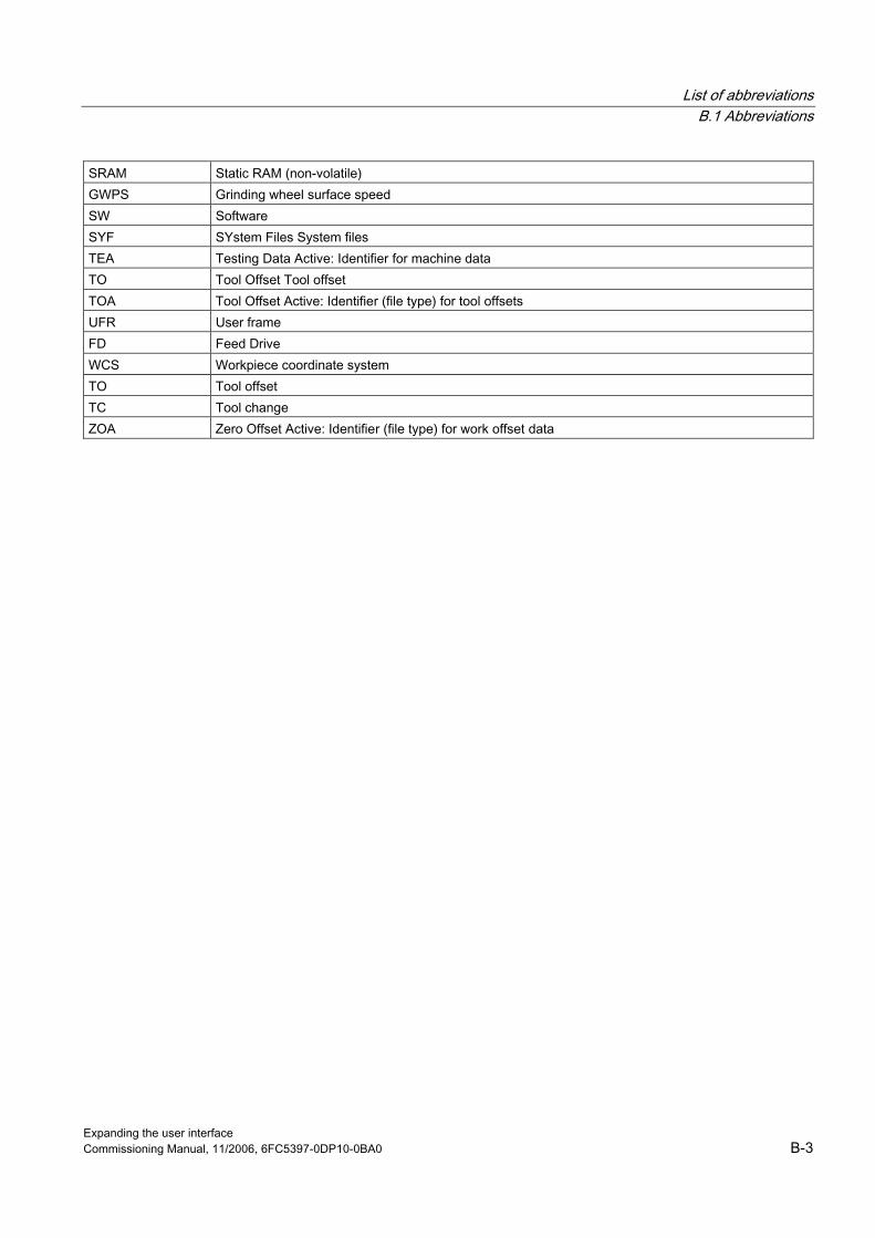
List of abbreviations B.1 Abbreviations
Expanding the user interface Commissioning Manual, 11/2006, 6FC5397-0DP10-0BA0 B-3
SRAM Static RAM (non-volatile) GWPS Grinding wheel surface speed SW Software SYF SYstem Files System files TEA Testing Data Active: Identifier for machine data TO Tool Offset Tool offset TOA Tool Offset Active: Identifier (file type) for tool offsets UFR User frame FD Feed Drive WCS Workpiece coordinate system TO Tool offset TC Tool change ZOA Zero Offset Active: Identifier (file type) for work offset data

List of abbreviations B.1 Abbreviations
Expanding the user interface B-4 Commissioning Manual, 11/2006, 6FC5397-0DP10-0BA0
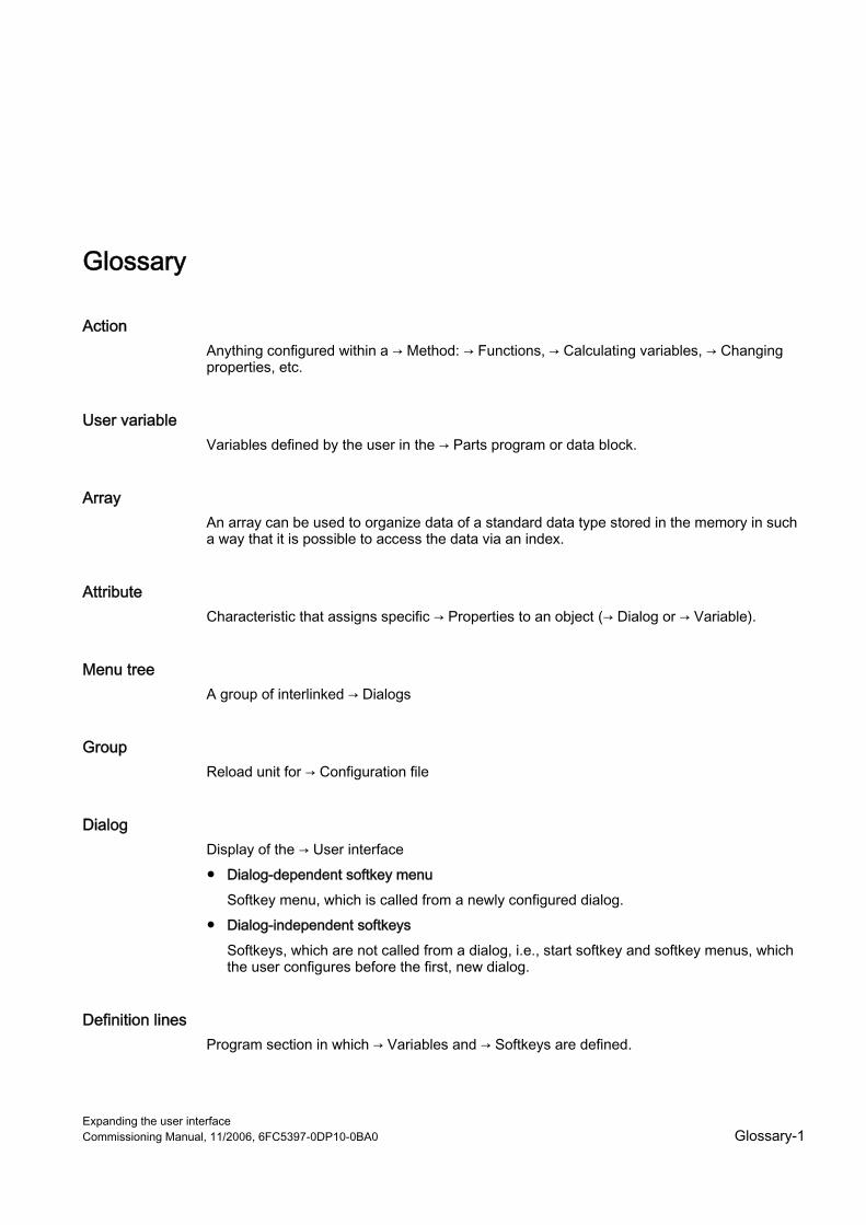
Expanding the user interface Commissioning Manual, 11/2006, 6FC5397-0DP10-0BA0 Glossary-1
Glossary
Action Anything configured within a → Method: → Functions, → Calculating variables, → Changing properties, etc.
User variable Variables defined by the user in the → Parts program or data block.
Array An array can be used to organize data of a standard data type stored in the memory in such a way that it is possible to access the data via an index.
Attribute Characteristic that assigns specific → Properties to an object (→ Dialog or → Variable).
Menu tree A group of interlinked → Dialogs
Group Reload unit for → Configuration file
Dialog Display of the → User interface ● Dialog-dependent softkey menu
Softkey menu, which is called from a newly configured dialog. ● Dialog-independent softkeys
Softkeys, which are not called from a dialog, i.e., start softkey and softkey menus, which the user configures before the first, new dialog.
Definition lines Program section in which → Variables and → Softkeys are defined.

Glossary
Expanding the user interface Glossary-2 Commissioning Manual, 11/2006, 6FC5397-0DP10-0BA0
Editor ASCII Editor with which characters can be entered in a file and edited.
Properties Characteristics of an object (e.g., of a → Variable)
Input/output field Also I/O field: for inputting or outputting variable values.
Start softkey → Softkey with which the first newly created → Dialog is started.
Event Any action, which initiates execution of a → Method: Input of characters, actuation of → Softkeys, etc.
Focus Part of the screen that is highlighted to identify the current → Element, e.g., where the cursor is positioned.
Function Sequence of operations programmed in → Methods as a function of → Parameters.
Help variable Internal arithmetic variable to which no → Properties can be assigned and is not, therefore, visible in the → Dialog.
Hotkeys 6 keys on OP 010, OP 010C and SINUMERIK keyboards with hotkey blocks. Pressing the keys selects an operating area directly. As an option, 2 additional keys can be configured as hotkeys.
HSx Horizontal → Softkey x
Interpreter The interpreter automatically converts the defined code from the → Configuration file into a → Dialog and controls its use.
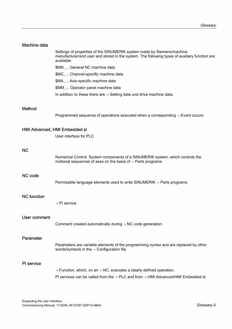
Glossary
Expanding the user interface Commissioning Manual, 11/2006, 6FC5397-0DP10-0BA0 Glossary-3
Machine data Settings of properties of the SINUMERIK system made by Siemens/machine manufacturer/end user and stored in the system. The following types of auxiliary function are available: $MN_... General NC machine data $MC_... Channel-specific machine data $MA_... Axis-specific machine data $MM_... Operator panel machine data In addition to these there are → Setting data und drive machine data.
Method Programmed sequence of operations executed when a corresponding → Event occurs.
HMI Advanced, HMI Embedded sl User interface for PLC
NC Numerical Control: System components of a SINUMERIK system, which controls the motional sequences of axes on the basis of → Parts programs.
NC code Permissible language elements used to write SINUMERIK → Parts programs.
NC function → PI service
User comment Comment created automatically during → NC code generation.
Parameter Parameters are variable elements of the programming syntax and are replaced by other words/symbols in the → Configuration file.
PI service → Function, which, on an → NC, executes a clearly defined operation. PI services can be called from the → PLC and from → HMI Advanced/HMI Embedded sl.
Glossary
Expanding the user interface Glossary-4 Commissioning Manual, 11/2006, 6FC5397-0DP10-0BA0
PLC Programmable Logic Control: Programmable controller, which performs mainly logic operations in the SINUMERIK system.
PLC keys PLC keys are provided as hotkeys via the PLC interface of the HMI software. The functions triggered by them in the HMI can be configured. They take the form of MCP keys or evaluations of PLC signal logic operations. For this reason, they are referred to as "virtual keys".
Programming support Provision of → Dialogs to assist programmers in writing → Parts programs with "higher-level" components
Configuration file File, which contains definitions and instructions that determine the appearance of → Dialogs and their → Functions.
Registers Memory for data exchange between→ Dialogs.
Recompile → NC code sections can be generated in a → Parts program from input fields in → Dialogs in the → Programming support system. Recompilation is the reverse operation. The input fields used to generate a selected section of NC code are retrieved from the NC code and displayed in the original dialog.
Setting data Data, which communicates the properties of the machine tool to the NC control, as defined by the system software. In contrast to → Machine data, setting data can be altered immediately by the operator.
ShopMill Optimized SINUMERIK application and user interface for 2½D milling operations.
ShopTurn Optimized SINUMERIK application and user interface for turning operations.
Glossary
Expanding the user interface Commissioning Manual, 11/2006, 6FC5397-0DP10-0BA0 Glossary-5
Simulation Simulation of a → Parts program run without movement of the actual machine axes.
Softkey Key on front of operator panel, which activates a function displayed on the assigned area of the screen.
Softkey labels Text/image on the screen, which is assigned to a → Softkey.
Softkey menu All horizontal or all vertical → Softkeys
Column index Column number of an array
Standard application → User interfaces that are integrated into standard software.
System variable NC variable providing the NC states for parts program accesses and accesses from → HMI.
Selecting A program formulated in the NC language, which specifies motion sequences for axes and various special actions.
Toggle field A list of values in the → Input/output field; check with toggle field: The value input in a field must be the same as one of the listed values.
Variable Designation of a memory location, which can be displayed in a → Dialog by assigning → Properties and in which input data and the results of arithmetic operations can be entered.
VSx Vertical → Softkey x
Glossary
Expanding the user interface Glossary-6 Commissioning Manual, 11/2006, 6FC5397-0DP10-0BA0
Line index Row number of an array
Access level Graduated system of authorization, which makes the accessibility and utilization of functions on the → User interface dependent on the authorization rights of the user.

Expanding the user interface Commissioning Manual, 11/2006, 6FC5397-0DP10-0BA0 Index-1
Index
A Action, 4-10 Array
Access mode, 2-44 Column index, 2-43 Compare mode, 2-44 Definition, 2-42 Element, 2-43 Line index, 2-43 Status, 2-47
Attributes, 2-22
B Background color, 2-23 Binary notation, 2-26
C Colors, 2-23, A-5 Command channel → Dialog, 3-4 Conditions, 2-112 Configuration file, 2-1, 2-2 Constants, 2-111 Custom
Features, 5-1 Hotkey, 5-3 Linking, 5-2
CUSTOM.COM, 5-4
D Default setting, 2-21 Defines softkey menu, 2-55 Dialog
Definition, 2-6 Definition block, 2-7 Enabling, 3-4 Header, 5-3 Multiple columns, 2-15 Number, 4-14
Properties, 2-10 Dialog change mode, 2-87 Dialog element, 2-13 DLL file, 2-105
E Exponential notation, 2-26
F Fig.
Deselection, 4-15 display as short text, 2-34 selecting, 4-15
File Copy, 2-75 Delete, 2-76 Transferring, 2-71, 2-89
Focus control, 2-51 Foreground color, 2-23 Function
AP (Activate Program), 2-71 CALL (Subprogram call), 2-73 CP (Copy Program), 2-75 CVAR (Check Variable), 2-74 DLGL (Dialog line), 2-75 DLL file, 2-70 DP (Delete Program), 2-76 EP (Exist Program), 2-79 EVAL (Evaluate), 2-77 EXE (Execute), 2-78 EXIT, 2-80 EXITLS (EXIT Loading Softkey), 2-81 FCT, 2-105 GC (Generate code), 2-82 INSTR (String), 2-100 LA (Load Array), 2-85 LB (Load Block), 2-86 LEFT (strings), 2-101 LEN (string), 2-100 LM (Load Mask), 2-87 LS (Load Softkey), 2-88 MIDS (strings), 2-102

Index
Expanding the user interface Index-2 Commissioning Manual, 11/2006, 6FC5397-0DP10-0BA0
MRNP (Multiple Read NC PLC), 2-91 Overview, 2-70 PI_SERVICE, 2-103 PI_START, 2-104 PP (Passivate Program), 2-89 Recompile NC code, 2-97 REFRESH (Update), 2-93 REPLACE (strings), 2-103 RETURN (Back), 2-96 RIGHT (strings), 2-102 RNP (Read NC PLC Variable), 2-90 SB (Search Backward), 2-98 SF (Search Forward), 2-98 SP (Select Program), 2-99 WNP (Write NC PLC Variable), 2-90
G Generates an NC code, 2-82 Graphic text, 2-21 Grid → Table grid, 2-47
H Hardkey block, 4-1 Hardkeys, 4-1 Help, 2-23 Help (HMI Advanced only), 2-29 Help display, 2-23 Help variable, 2-30 Hexadecimal notation, 2-26 HMI byte, 4-14 Hotkey event, 4-6, 4-9
I Input mode, 2-22
K Key
ETC, 4-10, 4-11 M (Machine), 4-2, 4-11 MENU SELECT, 4-2, 4-11 Recall, 2-57
KeyConfiguration, 4-18 Keys.ini, 4-6
L Limits, 2-21 Long text, 2-21
M Master dialog, 2-87 MD 9016
MM_SWITCH_TO_AREA, 5-2 Menu tree, 2-1 Method
CHANGE, 2-62 LOAD, 2-65 LOAD GRID, 2-64 OUTPUT, 2-66 Overview, 2-62 PRESS, 2-67 UNLOAD, 2-66
Multiple keypress, 4-6
N NC variable
Read, 2-90 Write, 2-90
O Operating area
change, 5-3 Custom, 5-1 Images, 4-16
Operator Bit, 2-112 Mathematical, 2-110
P PI services, 2-70 PLC interface, 4-12, 4-14 PLC program, 4-13 PLC softkey, 4-12 PLC variable
Read, 2-90 Write, 2-90
PLC-Byte, 4-14 Position
Input/output field, 2-23, 2-29 Short text, 2-23, 2-29

Index
Expanding the user interface Commissioning Manual, 11/2006, 6FC5397-0DP10-0BA0 Index-3
R Range of values, 4-9 Registers
Exchanging data, 2-94 Status, 2-95 Value, 2-94
Relational operators, 2-111 Return, 2-2
S Scratch buffer, 4-13 Security level, 2-56 Short text, 2-21 Softkey
Assign properties, 2-55 Properties, 2-58
Start softkey, 2-60 State, 4-10 Strings, 2-35 Sub-dialog, 2-87 Subprogram, 2-70
Block identifier, 2-72 Call, 2-73 cancel, 2-96 Variable, 2-72
System variable, 2-23, 2-31
T Table grid
Defining columns, 2-50 Definition, 2-47 Programming, 2-49
Task, 4-9
Text, 2-21 Text for units, 2-21 Toggle field, 2-27 Trigonometric functions, 2-111
U User variable, 2-23
V Variable
calculating, 2-31 Change property, 2-20 Check, 2-74 CURPOS, 2-36 CURVER, 2-37 End, 2-80 ENTRY, 2-38 ERR, 2-39 FILE_ERR, 2-40 FOC, 2-41 S_CHAN, 2-42
Variable status, 2-20 Variable type, 2-21
INTEGER, 2-24 VARIANT, 2-25
Variable value, 2-19 Virtual keys, 4-9
W Write mode, 2-23

Index
Expanding the user interface Index-4 Commissioning Manual, 11/2006, 6FC5397-0DP10-0BA0
Programming help systems 1
Alarm/Machine data help 2
SINUMERIK
SINUMERIK 840D sl/840Di sl/810D Online Help (HE1)
Commissioning Manual
11/2006 6FC5397-0DP10-0BA0
Valid for: control system SINUMERIK 840D sl/840DE sl SINUMERIK 840Di sl/840DiE sl SINUMERIK 840D/840DE SINUMERIK 840Di/840DiE SINUMERIK 810D/810DE Software Software Version HMI Advanced 7.3

Safety Guidelines This manual contains notices you have to observe in order to ensure your personal safety, as well as to prevent damage to property. The notices referring to your personal safety are highlighted in the manual by a safety alert symbol, notices referring only to property damage have no safety alert symbol. These notices shown below are graded according to the degree of danger.
Danger
indicates that death or severe personal injury will result if proper precautions are not taken.
Warning
indicates that death or severe personal injury may result if proper precautions are not taken.
Caution
with a safety alert symbol, indicates that minor personal injury can result if proper precautions are not taken.
Caution
without a safety alert symbol, indicates that property damage can result if proper precautions are not taken.
Notice
indicates that an unintended result or situation can occur if the corresponding information is not taken into account.
If more than one degree of danger is present, the warning notice representing the highest degree of danger will be used. A notice warning of injury to persons with a safety alert symbol may also include a warning relating to property damage.
Qualified Personnel The device/system may only be set up and used in conjunction with this documentation. Commissioning and operation of a device/system may only be performed by qualified personnel. Within the context of the safety notes in this documentation qualified persons are defined as persons who are authorized to commission, ground and label devices, systems and circuits in accordance with established safety practices and standards.
Prescribed Usage Note the following:
Warning
This device may only be used for the applications described in the catalog or the technical description and only in connection with devices or components from other manufacturers which have been approved or recommended by Siemens. Correct, reliable operation of the product requires proper transport, storage, positioning and assembly as well as careful operation and maintenance.
Trademarks All names identified by ® are registered trademarks of the Siemens AG. The remaining trademarks in this publication may be trademarks whose use by third parties for their own purposes could violate the rights of the owner.
Disclaimer of Liability We have reviewed the contents of this publication to ensure consistency with the hardware and software described. Since variance cannot be precluded entirely, we cannot guarantee full consistency. However, the information in this publication is reviewed regularly and any necessary corrections are included in subsequent editions.
Siemens AG Automation and Drives Postfach 48 48 90437 NÜRNBERG GERMANY
Order No.: 6FC5397-0DP10-0BA0 Ⓟ 12/2006
Copyright © Siemens AG 2006. Technical data subject to change

Online Help (HE1) Commissioning Manual, 11/2006, 6FC5397-0DP10-0BA0 3
Table of contents 1 Programming help systems ....................................................................................................................... 5
1.1 Overview ........................................................................................................................................5 1.2 Quick "ASCII" help .........................................................................................................................8 1.2.1 Extending/replacing the help function............................................................................................8 1.2.2 Entries in the file "IF.INI" ................................................................................................................8 1.2.3 Extension of text files ...................................................................................................................11 1.2.4 Extension of a topic......................................................................................................................13 1.2.5 Extension of an instruction...........................................................................................................14 1.2.6 Parameterization of extended "PDF" help ...................................................................................15 1.2.7 Extension with alarm text variables .............................................................................................18 1.3 Extended "PDF" help ...................................................................................................................18 1.3.1 Function .......................................................................................................................................18 1.3.2 Extending programming help .......................................................................................................19 1.4 ISO mode help .............................................................................................................................21 1.4.1 Function .......................................................................................................................................21 1.4.2 Extending ISO mode help ............................................................................................................22
2 Alarm/Machine data help ......................................................................................................................... 25 2.1 Overview ......................................................................................................................................25 2.2 Alarm help ....................................................................................................................................28 2.2.1 Function .......................................................................................................................................28 2.2.2 Extending alarm help ...................................................................................................................29 2.2.3 User comments on help ...............................................................................................................30 2.2.4 Changing "Win-Help" alarm help to "PDF help"...........................................................................31 2.3 Machine data help........................................................................................................................32 2.3.1 Function .......................................................................................................................................32 2.3.2 Extending the machine data help.................................................................................................33
Index........................................................................................................................................................ 35
Tables
Table 1-1 Topic IDs ......................................................................................................................................13 Table 1-2 Defined topic IDs..........................................................................................................................13

Table of contents
Online Help (HE1) 4 Commissioning Manual, 11/2006, 6FC5397-0DP10-0BA0

Online Help (HE1) Commissioning Manual, 11/2006, 6FC5397-0DP10-0BA0 5
Programming help systems 11.1 Overview
Programming help systems The extendible programming help systems listed below are available on the PCU 50.3 controller: • Quick "ASCII" help • Extended "PDF" help
– Additional help (PDF file) from the quick "ASCII" help – Additional help on input fields of cycle parameterization screens – ISO mode help
The functionality and extendibility of these help systems is described in the sections below.
Software • HMI Advanced • Adobe Reader 4.x (available free over the Internet/from specialist dealer)
The Adobe Acrobat Reader 4.x software is supplied on the SINUMERIK 840D sl controller as standard.
• Adobe Acrobat 4.x You will need the Adobe Acrobat Distiller 4.x software in order to convert documents to PDF and for editing documents once they are available in this format.
Storage locations of help files Programming help: F:\DH\CST.DIR\HLP.DIR (may contain HLP, PDF and TXT files) Alarm/MD help: F:\MMC2\HLP (may contain HLP, PDF and TXT files) OPI help: F:\HMI_ADV\HLP (may contain HLP, PDF and TXT files)
Programming help systems 1.1 Overview
Online Help (HE1) 6 Commissioning Manual, 11/2006, 6FC5397-0DP10-0BA0
Principle of PDF help The PDF help depends on the following components being available in the help file storage location: • Call file, e.g., PG_GR.TXT, with the information:
<PDF file name> <ID> <search term> for each call • Associated PDF file Proceed as follows to call up the help: • Start Adobe Acrobat Reader (supplied with the controller) • Jump to page number (must be defined by index in document) • Search for term (Adobe software search function)
Creation procedure • Define jumps in the help document (e.g., using standard index function of DTP systems)
and generate • Store jump file as text file • Assign ID numbers to the programming commands • Generate PDF file Result: • A call file (text file) with the information:
<PDF file name> <ID> <search term> for each call • One or more associated PDF files
Note In the event of multiple jumps for the same topic, each page must be entered on a separate line. Example: 840D_PG.PDF 44 155 840D_PG.PDF 45 180 840D_PG.PDF 46 199
Hint: In the case of a larger volume of indices, the call file can be created automatically using Microsoft Excel: • Insert "index file" (*.TXT) in Excel • Insert column • Enter the name of the PDF file on the first line • Select the menu items "Edit" – "Fill" – "Down"

Programming help systems 1.1 Overview
Online Help (HE1) Commissioning Manual, 11/2006, 6FC5397-0DP10-0BA0 7
• Copy the data and • Save as "TXT" file The syntax below is left over: <PDF file name> <ID> <search term> 840D_PG.PDF 44 155
Testing the jumps in the document Proceed as follows to test whether all the search strings can be found: • Start Adobe Acrobat • Select the menu item "Edit" –> "Find" (CTRL + F) • Enter the search string.
Note If the search strings cannot be found, possible causes include: • Incorrect input • The texts were not converted properly during PDF generation and cannot be found by
the search engine for that reason. Analysis:Select a string you are looking for using Adobe Acrobat, copy it and paste it into a Word document. Remedy:
• Generate the PDF again or • Generate the postscript file using Adobe printer driver Adobe PS 5.1.1 and then
convert it using Adobe Distiller.
Search sequence The help adheres to the search sequence below: • F:\USER\HLP • F:\ OEM\HLP • F:\ ADD_ON\HLP • F:\MMC2\HLP • F:\HMI_ADV\HLP • F:\ DH\CUS.DIR\HLP.DIR (user directory) • F:\ DH\CMA.DIR\HLP.DIR (manufacturer directory) • F:\ DH\CST.DIR\HLP.DIR (Siemens directory) • F:\ DH\COM.DIR\HLP.DIR
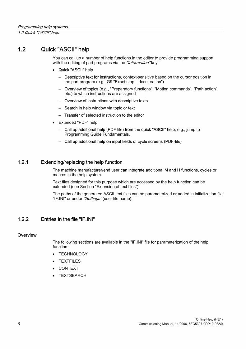
Programming help systems 1.2 Quick "ASCII" help
Online Help (HE1) 8 Commissioning Manual, 11/2006, 6FC5397-0DP10-0BA0
1.2 Quick "ASCII" help You can call up a number of help functions in the editor to provide programming support with the editing of part programs via the "Information" key: • Quick "ASCII" help
– Descriptive text for instructions, context-sensitive based on the cursor position in the part program (e.g., G9 "Exact stop – deceleration")
– Overview of topics (e.g., "Preparatory functions", "Motion commands", "Path action", etc.) to which instructions are assigned
– Overview of instructions with descriptive texts – Search in help window via topic or text – Transfer of selected instruction to the editor
• Extended "PDF" help – Call up additional help (PDF file) from the quick "ASCII" help, e.g., jump to
Programming Guide Fundamentals. – Call up additional help on input fields of cycle screens (PDF-file)
1.2.1 Extending/replacing the help function The machine manufacturer/end user can integrate additional M and H functions, cycles or macros in the help system. Text files designed for this purpose which are accessed by the help function can be extended (see Section "Extension of text files"). The paths of the generated ASCII text files can be parameterized or added in initialization file "IF.INI" or under "Settings" (user file name).
1.2.2 Entries in the file "IF.INI"
Overview The following sections are available in the "IF.INI" file for parameterization of the help function: • TECHNOLOGY • TEXTFILES • CONTEXT • TEXTSEARCH

Programming help systems 1.2 Quick "ASCII" help
Online Help (HE1) Commissioning Manual, 11/2006, 6FC5397-0DP10-0BA0 9
TECHNOLOGY section The relevant technology category of the connected machine can be entered in the [TECHNOLOGY] section so as to limit the display of instruction texts to relevant technology entries, i.e., only entries pertinent to the relevant technology are displayed. The following technology codes can be specified: "m" = Milling "t" = Turning "g" = Grinding "s" = Nibbling "p" = Punching "a" = Display all technologies
TEXTFILES section The paths (path\name) used for the Short Help text files on which the help function is based are parameterized in the [TEXTFILES] section. The help function accesses the following text files: • Siemens "DH\CST.DIR\IFS_GR.COM" • Machine manufacturer "DH\CMA.DIR\IFM_GR.COM" (any file name) • End user "DH\CUS.DIR\USER_GR.COM" (any file name)
(entered under "Settings").
Note The path for the Siemens text file "DH\CST.DIR\lFS_GR.COM" must exist, otherwise an error message is output.
There are different parameterization options for the names of the text files when assigning the text path. The following table lists the parameterization options and their interpretation by the help function.
Parameters for the text file Interpretation FileName.com The non-language-specific text file is read out FileName_XX.com (XX = language code, e.g., "GR" for German, for language codes see "Other languages" under "Alarm help")
The language-specific text file is read out
Example: ENDUSER=CUS.DIR\IFM_.COM First of all, an attempt is made to open the non-language-specific text file "IFM.COM" in the path "C:\DH\CUS.DIR\" but, if the non-language-specific text file does not exist, the relevant language-specific text file (e.g., "IFM_GR.COM") is opened instead.
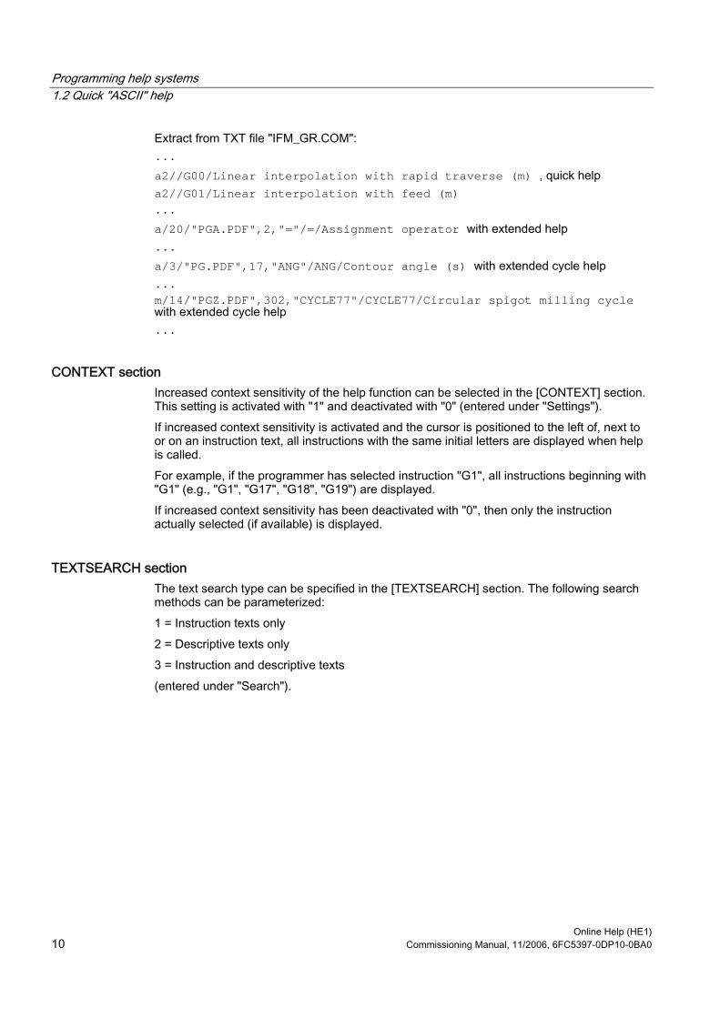
Programming help systems 1.2 Quick "ASCII" help
Online Help (HE1) 10 Commissioning Manual, 11/2006, 6FC5397-0DP10-0BA0
Extract from TXT file "IFM_GR.COM": ... a2//G00/Linear interpolation with rapid traverse (m) , quick help a2//G01/Linear interpolation with feed (m) ... a/20/"PGA.PDF",2,"="/=/Assignment operator with extended help ... a/3/"PG.PDF",17,"ANG"/ANG/Contour angle (s) with extended cycle help ... m/14/"PGZ.PDF",302,"CYCLE77"/CYCLE77/Circular spigot milling cycle with extended cycle help ...
CONTEXT section Increased context sensitivity of the help function can be selected in the [CONTEXT] section. This setting is activated with "1" and deactivated with "0" (entered under "Settings"). If increased context sensitivity is activated and the cursor is positioned to the left of, next to or on an instruction text, all instructions with the same initial letters are displayed when help is called. For example, if the programmer has selected instruction "G1", all instructions beginning with "G1" (e.g., "G1", "G17", "G18", "G19") are displayed. If increased context sensitivity has been deactivated with "0", then only the instruction actually selected (if available) is displayed.
TEXTSEARCH section The text search type can be specified in the [TEXTSEARCH] section. The following search methods can be parameterized: 1 = Instruction texts only 2 = Descriptive texts only 3 = Instruction and descriptive texts (entered under "Search").
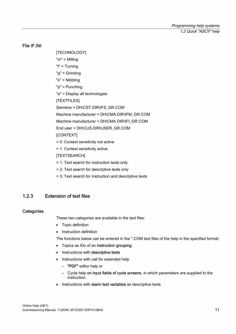
Programming help systems 1.2 Quick "ASCII" help
Online Help (HE1) Commissioning Manual, 11/2006, 6FC5397-0DP10-0BA0 11
File IF.INI [TECHNOLOGY] "m" = Milling "t" = Turning "g" = Grinding "s" = Nibbling "p" = Punching "a" = Display all technologies [TEXTFILES] Siemens = DH\CST.DIR\IFS_GR.COM Machine manufacturer = DH\CMA.DIR\IFM_GR.COM Machine manufacturer = DH\CMA.DIR\IFI_GR.COM End user = DH\CUS.DIR\USER_GR.COM [CONTEXT] = 0: Context sensitivity not active = 1: Context sensitivity active [TEXTSEARCH] = 1: Text search for instruction texts only = 2: Text search for descriptive texts only = 3: Text search for instruction and descriptive texts
1.2.3 Extension of text files
Categories These two categories are available in the text files: • Topic definition • Instruction definition The functions below can be entered in the *.COM text files of the help in the specified format: • Topics as IDs of an instruction grouping • Instructions with descriptive texts • Instructions with call for extended help
– "PDF" editor help or – Cycle help on input fields of cycle screens, in which parameters are supplied to the
instruction • Instructions with alarm text variables as descriptive texts

Programming help systems 1.2 Quick "ASCII" help
Online Help (HE1) 12 Commissioning Manual, 11/2006, 6FC5397-0DP10-0BA0
One line is available for each of these in the associated text file. The screenshot below shows an example:
Figure 1-1 Siemens text file
The topic definition contains the following parameters:
Topic definition Technology code "r"/topic ID/topic name The instruction definition contains the following parameters:
Instruction definition Technology/topic ID/extended help/instruction text/ descriptive text
Note Within each of the individual text files, the Siemens topics are displayed first, followed by those of the machine manufacturer and finally those of the end user. The specified sequence only appears if the topics are declared first and then the instructions of the text file. The instructions in the text files must be stored in alphabetical order if the standard, machine manufacturer and end user instructions are to be sorted correctly.

Programming help systems 1.2 Quick "ASCII" help
Online Help (HE1) Commissioning Manual, 11/2006, 6FC5397-0DP10-0BA0 13
1.2.4 Extension of a topic
Extension of a topic A topic represents an instruction grouping which can be used for displaying instructions. One line for the topic definition contains the following 3 parameters:
Topic definition Technology code "r"/topic ID/topic name The following line could then appear in the text file, for example: r/2/Motion commands r: Permanently defined in topic definitions 2: Topic ID used for assigning instructions. Motion commands: Topic name The "/" character separates the parameters and may only be used as a text character in the last parameter. The length of the topic name is limited by the display and must not exceed 40 characters with a standard text size of 8 pt, for example. The following topic IDs are reserved:
Table 1-1 Topic IDs
Topic ID User 0..49 Siemens 50...99 Machine manufacturer From 100 End user
The following topic IDs exist as standard in the Siemens text file:
Table 1-2 Defined topic IDs
Topic ID Topic name Topic ID Topic name 1 Preparatory functions 13 Program handling 2 Motion commands 14 Standard cycles 3 Path action 15 Measuring cycles 4 Feedrate 16 Measurement 5 Spindle 17 Synchronized actions 6 Axis handling 18 Interrupt handling 7 M functions 19 String/field operations 8 H functions 20 Math. functions/operators 9 Offsets 21 Definitions 10 Transformations 22 High-level language elements 11 Tool management/
compensation 23 Parameters
12 Technology functions 24 System variables

Programming help systems 1.2 Quick "ASCII" help
Online Help (HE1) 14 Commissioning Manual, 11/2006, 6FC5397-0DP10-0BA0
1.2.5 Extension of an instruction
Extension of an instruction An instruction contains descriptive texts, e.g., "G0/Linear interpolation with rapid traverse". An instruction is assigned to a topic via the topic ID.
Parameters of instruction definition An instruction definition contains the following parameters: Technology/topic ID/extended help/instruction text/descriptive text Example of editor help: a/20/"PGA.PDF",2,"="/=/Assignment operator a: Milling technology 20: Standard cycles topic ID "PGA.PDF",2,"=": Extended help on command "=" =: Instruction text Assignment operator: Descriptive text If the above line is entered in one of the user text files (e.g., IFM_GR.COM), help file "PGA.PDF" is called up for the command "=" and the relevant help section is displayed. Example of cycle help: m/14/"PGZ.PDF",302,"CYCLE83"/CYCLE83/Deep-hole drilling milling cycle m: Milling technology 14: Standard cycles topic ID "PGZ.PDF",302,"RTP": Extended help for "RTP" parameter on the cycle parameterization screenform CYCLE83: Instruction text CYCLE83 Deep-hole drilling milling cycle: Descriptive text If the above line is entered in one of the user text files, user cycle "CYCLExx" is supported by the help system. It is displayed if • either technology-independent code "a" • or miller-specific code "m" has been entered in initialization file "IF.INI". It is assigned to "Standard cycles" via topic ID "14" and can, therefore, also be found via the corresponding entry in the topic search. The last parameter contains the descriptive text, which is displayed in the relevant column of the help system, and which is designed to give the user an initial indication as to the function of the cycle. The "/" character separates the parameters and may only be used as a text character in the last parameter.
Programming help systems 1.2 Quick "ASCII" help
Online Help (HE1) Commissioning Manual, 11/2006, 6FC5397-0DP10-0BA0 15
Technology The following characters are defined for specifying the technology category: "m" = Milling "t" = Turning "g" = Grinding "s" = Nibbling "p" = Punching "a" = Display for all technologies
Note Entries are separated by commas so as to enable them to be assigned to several technologies and different topics.
Topic ID The topic ID is used for assigning instructions of a particular topic to the topic definition and for displaying these under the topic.
Integrating additional commands If additional commands and a brief description are to be integrated in the help, these must be incorporated using the syntax described above in file IfM_gr.com (any file name), which is stored in directory Dh\CMA.dir\. If an additional help (extended "PDF" help) is to be called up for these commands, the parameter "Extended help" must be edited as described in the section below.
1.2.6 Parameterization of extended "PDF" help
Calling extended help A special entry in the "Extended help" parameter of the instruction definition makes it possible to call up an extended "PDF" help as an online help in addition to the quick help. This may contain detailed information on the selected command, for example. The following calls are possible: • Editor help:
Jump directly to the help (PDF file) from the quick "ASCII" help for a term (command) in the program editor.
• Cycle help: Jump to the help (PDF file) from an input field of the cycle screen.

Programming help systems 1.2 Quick "ASCII" help
Online Help (HE1) 16 Commissioning Manual, 11/2006, 6FC5397-0DP10-0BA0
Parameters of instruction definition Technology/topic ID/extended help/instruction text/descriptive text
Extended help The following entries are possible in the "Extended help" parameter: • Editor help
/"PDF file name", help ID, "search string"/ • Cycle help
/"PDF file name", help ID, "search string" (file name, help screen)/
Two commas must be inserted in the "Extended help" parameter even if no entries need to be made. Example: The declaration line requires the following parameters, for example: m,t/14/"PDF filename", help ID, "search string" (file name, help screen)/CYCLE82/drilling cycle, drilling, counterboring The meanings of the entries for the "Extended help" parameter are as follows: PDF file name = File from which the descriptive text is to be displayed Help ID = Unique assignment to term for which the help is to be displayed Search string = Search string in the PDF file which is to be displayed in the help text (File name, help screen) = Name of file in which the help screens are stored and the name of the help screen which is to be displayed (-> only relevant for cycle help) CYCLE82 = Instruction text Drilling cycle, drilling, counterboring = Descriptive text Call example: m,t/14/"PGZ.PDF",1,"RTP"(drilling,CYC82)/CYCLE82/drilling cycle, drilling, counterboring
Note If you only want to access the PDF file, only these parameters should then appear in the "Extended help" section. E.g.: m,t/14/"PGZ.PDF",1,"RTP"/CYCLE82/drilling cycle, drilling, counterboring If you only want to display the help screen, only these parameters should then appear in the "Extended help" section. E.g.: m,t/14/,,(drilling,CYC82)/CYCLE82/drilling cycle, drilling, counterboring

Programming help systems 1.2 Quick "ASCII" help
Online Help (HE1) Commissioning Manual, 11/2006, 6FC5397-0DP10-0BA0 17
Instruction text An instruction text could be "G17", for example. This text is transferred to the part program currently being edited when the "Transfer to editor" command is issued. The instruction text can be approx. 12 characters long.
Descriptive text The descriptive text is the help text which describes the instruction in more detail. The length of the descriptive text is limited by the display and must not exceed 40 characters with a standard text size of 8 pt, for example.
Multiple jumps Several help references can be stored in ring formation (i.e., the first help is displayed again after the last help) for each help element. E.g.: m,t/14/"Hlp.pdf",1,"Help1",,2,"Help2","Help3.pdf",3,,/ CYCLE82/drilling cycle, drilling, counterboring I.e.: • Entry in help text ring
File: HLP.PDF Index: 1 Text: Help1
• Entry in help text ring File: HLP.PDF Index: 2 Text: Help2
• Entry in help text ring File: HELP3.PDF Index: 3 Text: Help2
The components of a block are remembered by the previous block, as illustrated in the example, so as to avoid repetitions. Only complete blocks are transferred.
Note Two commas must be inserted in the "Extended help" parameter even if no entries need to be made.
Programming help systems 1.3 Extended "PDF" help
Online Help (HE1) 18 Commissioning Manual, 11/2006, 6FC5397-0DP10-0BA0
1.2.7 Extension with alarm text variables
Function A special situation with respect to parameterization of the section for descriptive texts or topic names is to store these in the section instead of the descriptive texts ("alarm text variables"). These variables begin with "$". E.g., m/14//CYCLExx/$888888 Instead of entering the descriptive text directly in the help text file, this is entered under alarm text variable "$888888", for example. The actual declaration of the descriptive text is therefore stored in a user-specific alarm text file. The result is a non-language-specific text file.
1.3 Extended "PDF" help
1.3.1 Function You can call up a number of help functions in the editor to provide programming support with the editing of part programs via the "Information" key: • Quick "ASCII" help
– Descriptive text for instructions, context-sensitive based on the cursor position in the part program (e.g., G9 "Exact stop – deceleration")
– Overview of topics (e.g., "Preparatory functions", "Motion commands", "Path action", etc.) to which instructions are assigned
– Overview of instructions with descriptive texts – Search in help window via topic or text – Transfer of selected instruction to the editor
• Extended "PDF" help – Call up additional help (PDF file) from the quick "ASCII" help, e.g., jump to
Programming Guide Fundamentals. – Call up additional help on input fields of cycle screens (PDF-file)
Programming help systems 1.3 Extended "PDF" help
Online Help (HE1) Commissioning Manual, 11/2006, 6FC5397-0DP10-0BA0 19
1.3.2 Extending programming help A special entry in the "Extended help" parameter of the instruction definition makes it possible to integrate an extended help in addition to the quick help (e.g., detailed information on the selected command). The following calls are possible: • Editor help:
Jump directly to the help (PDF file) from the quick "ASCII" help for a term (command) in the program editor. Preconditions: A list of additional commands which are to be displayed in the quick help has already been created as described in Section "Extension of text files" (e.g., IFM_GR.COM) and is stored in the controller. This allows you to call up the extended help after the quick help using the Info key. Please note that the list of commands for the quick help is identical to the list for the extended help (concordance).
• Cycle help: Jump to the help (PDF file) from an input field of the cycle screen.
Parameters of instruction definition Technology/topic ID/extended help/instruction text/ descriptive text "Extended help": The following entries are possible in the "Extended help" parameter: • Editor help
/"PDF file name", help ID, "search string"/ Example: a/20/"PGA.PDF",2,"="/=/Assignment operator
• Cycle help /"PDF file name", help ID, "search string" (file name, help screen)/ Example: a/3/"PG.PDF",17,"ANG"/ANG/Contour angle (s)
Necessary files • IFM_GR.COM: Text file with program commands and brief description • *.PDF: Help file, e.g., 840D_PG_GR.PDF • *.txt: Jump file, e.g., 840D_PG_GR.TXT
1) Define jump labels in document The jumps must be identified by an index entry and a single-column index list (right-justified page numbers) must be generated in the document (e.g., Winword) from which sections are to be displayed on the controller as a PDF. If several jumps are required for one command, the same number of index labels must be created.

Programming help systems 1.3 Extended "PDF" help
Online Help (HE1) 20 Commissioning Manual, 11/2006, 6FC5397-0DP10-0BA0
2) Generate text file Copy the single-column index generated above (right-justified page numbers) and save it in a text file (*.TXT). Example: MEAW 155 <Search string> <page> The text file for the PDF call requires the following syntax: <PDF file name> <ID> <page> Enter the name of the PDF file (without the language code) at the start of each line. Example: 840D_PG.PDF MEAW 155 <PDF name> <ID> <page>
3) Define ID numbers ID numbers unique to each document (e.g., 1...n) must be defined for the search strings. The ID numbers correspond to the list of instructions of the quick "ASCII" help, as the detailed descriptions corresponding to the brief descriptions are to be displayed. Example: 840D_PG.PDF 44 MEAW 155 <PDF file name> <ID> <search string> <page> Now delete the "search string" column such that the syntax below remains: Result: <PDF file name> <ID> <page> 840D_PG.PDF 44 155
4) Generate PDF file Print your document as a postscript file and convert this to PDF format using Adobe Acrobat Distiller.
5) Read files into controller The generated files (*.PDF and *.TXT) must now be read into the controller, e.g., into directory F:\ DH\CUS.DIR\HLP.
Programming help systems 1.4 ISO mode help
Online Help (HE1) Commissioning Manual, 11/2006, 6FC5397-0DP10-0BA0 21
Note In the case of a larger volume of indices, the call file can be created automatically using Microsoft Excel: • Insert text file (*.TXT) in Excel • Insert column • Enter the name of the PDF file on the first line • Select "Edit > Fill" • Now delete the "search string" column such that the syntax below remains:
<PDF file name> <ID> <page> 840D_PG.PDF 44 155
• Copy the data and • Save as "TXT" file
1.4 ISO mode help
1.4.1 Function
Function The 840D/840D sl-specific help systems are displayed as standard: • Help in the editor • Alarm help • Machine data help If ISO dialect 0 help systems are to be displayed, a distinction must be made as to which data is to be displayed, as the same commands can have multiple meanings, for example. The [TEXTFILES] section of the "IF.INI" file has been extended by the entry SiemensI=CST.DIR\IFIT_COM (turning technology) or SiemensI=CST.DIR\IFIM_COM (milling technology) for this reason. This specifies the path (CST.DIR) and the name (IFIT_COM or IFIM_COM) for the ISO mode quick "ASCII" help. The extended "PDF" help can thus be called from the quick "ASCII" help.
IF.INI [TEXTFILES] [TEXTFILES] ;text files containing the information shown in the help system Siemens=cst.dir\ifs_.com SiemensI=cst.dir\ifit_.com or ifim_.com Manufacturer= End user=
Programming help systems 1.4 ISO mode help
Online Help (HE1) 22 Commissioning Manual, 11/2006, 6FC5397-0DP10-0BA0
Necessary files • List of "ISO dialect 0" commands with the associated brief description • TXT file for the jump to the PDF file • PDF file which is to be displayed in the help
Program execution The help checks the following machine data on startup: • MD18800 MM_EXTERN_LANGUAGE
If the MD is activated, the controller switches over to the ISO dialect 0 mode. If MD18800 = 1, MD20150 is evaluated.
• MD20150 GCODE_RESET_VALUES[n(active channel),47] If MD20150 [47] = 2, the file entered in the INI file under "SiemensI" (ISO mode) is used (otherwise the file under "Siemens" is used).
• MD10880 MM_EXTERN_CNC_LANGUAGE MD10880 specifies whether the controller is to be designed for turning or milling in ISO mode.
1.4.2 Extending ISO mode help If additional descriptions are to be displayed in the ISO mode help, these must be inserted in the form specified below: • As a list of ISO mode commands with a brief description in the directory
"SiemensI=CST.DIR\" as file "IFIT_COM" or file "IFIM_COM" (refer to Section "Extension of text files")
• As a help description (PDF file) and a TXT file of the same name in directory "F:\USER\HLP"
Parameters of instruction definition Technology/topic ID/extended help/instruction text/ descriptive text "Extended help": The following entries are possible in the "Extended help" parameter: • Editor help
/"PDF file name", help ID, "page number"/ • Cycle help
/"PDF file name", help ID, "page number" (file name, help screen)/
Programming help systems 1.4 ISO mode help
Online Help (HE1) Commissioning Manual, 11/2006, 6FC5397-0DP10-0BA0 23
Necessary files • IFIT_.COM or IFIM_.COM: Text file with ISO mode commands and brief description • *.PDF: e.g., 840D_PGIT_GR.PDF • *.TXT: e.g., 840D_PITG_GR.TXT
1) Define jump labels in document The jump labels must be identified by an index entry and a single-column index list (right-justified page numbers) must be generated in the document (e.g., Winword) which is to be displayed on the controller as a PDF.
2) Generate text file Copy the single-column index generated above (right-justified page numbers) and save it in a TXT file. Example: G65 155 <Search string> <page> The text file for the PDF call now requires the following syntax: <PDF file name> <search string> <page> Enter the name of the PDF file (without the language code) at the start of each line. Example: 840D_PGIT.PDF G65 155 <PDF name> <search string> <page>
3) Define ID numbers ID numbers unique to each document (e.g., 1...n) must be defined for the search strings. The ID numbers correspond to the list of instructions of the quick "ASCII" help, as the detailed descriptions corresponding to the brief descriptions are to be displayed. Example: 840D_PGIT.PDF 44 MEAW 155 <PDF file name> <ID> <search string> <page> Now delete the "search string" column such that the syntax below remains: Result: <PDF file name> <ID> <page> 840D_PGIT.PDF 44 155
4) Generate PDF file Print your document as a postscript file and convert this to PDF format using Adobe Acrobat Distiller.

Programming help systems 1.4 ISO mode help
Online Help (HE1) 24 Commissioning Manual, 11/2006, 6FC5397-0DP10-0BA0
5) Read files into controller The generated files (*.PDF and *.TXT) must now be read into directory F:\USER\HLP on the controller.
Note In the case of a larger volume of indices, the call file can be created automatically using Microsoft Excel: • Insert text file (*.TXT) in Excel • Insert column • Enter the name of the PDF file on the first line • Select "Edit > Fill" • Now delete the "search string" column such that the syntax below remains:
<PDF file name> <ID> <page> 840D_PGIT.PDF 44 155
• Copy the data and • Save as "TXT" file

Online Help (HE1) Commissioning Manual, 11/2006, 6FC5397-0DP10-0BA0 25
Alarm/Machine data help 22.1 Overview
The functionality and extendibility of the alarm and machine data help are described in the sections below.
Software • HMI Advanced • Adobe Reader 4.x (available free over the Internet/from specialist dealer)
The Adobe Acrobat Reader 4.x software is supplied on the SINUMERIK 840D/840D sl controller as standard.
• Adobe Acrobat 4.x You will need the Adobe Acrobat Distiller 4.x software in order to convert documents to PDF and for editing documents once they are available in this format.
Storage locations of help files Programming help: F:\DH\CST.DIR\HLP.DIR (may contain HLP, PDF and TXT files) Alarm/MD help: F:\MMC2\HLP (may contain HLP, PDF and TXT files) OPI help: F:\HMI_ADV\HLP (may contain HLP, PDF and TXT files)
Principle of PDF help The PDF help depends on the following components being available in the help file storage location: • Call file, e.g., PG_GR.TXT, with the information:
<PDF file name> <ID> <search term> for each call • Associated PDF file Proceed as follows to call up the help: • Start Adobe Acrobat Reader (supplied with the controller) • Jump to page number (must be defined by index in document) • Search for term (Adobe software search function)
Alarm/Machine data help 2.1 Overview
Online Help (HE1) 26 Commissioning Manual, 11/2006, 6FC5397-0DP10-0BA0
Creation procedure • Define jumps in the help document (e.g., using standard index function of DTP systems)
and generate • Store jump file as text file • Generate PDF file Result: • A call file (text file) with the information:
<PDF file name> <ID> <search term> for each call • One or more associated PDF files
Note In the event of multiple jumps for the same topic, each page must be entered on a separate line. Example: 840D_PG.PDF 44 155 840D_PG.PDF 45 180 840D_PG.PDF 46 199
Hint: In the case of a larger volume of indices, the call file can be created automatically using Microsoft Excel: • Insert "index file" (*.TXT) in Excel • Insert column • Enter the name of the PDF file on the first line • Select the menu items "Edit" – "Fill" –> "Down" • Copy the data and • Save as "TXT" file The syntax below is left over: <PDF file name> <ID> <search term> 840D_PG.PDF 44 155

Alarm/Machine data help 2.1 Overview
Online Help (HE1) Commissioning Manual, 11/2006, 6FC5397-0DP10-0BA0 27
Testing the jumps in the document Proceed as follows to test whether all the search strings can be found: • Start Adobe Acrobat • Select the menu item "Edit" –> "Find" (CTRL + F) • Enter the search string.
Note If the search strings cannot be found, possible causes include: • Incorrect input • The texts were not converted properly during PDF generation and cannot be found by
the search engine for that reason. Analysis:Select a string you are looking for using Adobe Acrobat, copy it and paste it into a Word document. Remedy: – Generate the PDF again or – Generate the postscript file using Adobe printer driver Adobe PS 5.1.1 and then
convert it using the Adobe Distiller.
Search sequence The help adheres to the search sequence below: • F:\USER\HLP • F:\ OEM\HLP • F:\ ADD_ON\HLP • F:\MMC2\HLP • F:\HMI_ADV\HLP • F:\ DH\CUS.DIR\HLP.DIR (user directory) • F:\ DH\CMA.DIR\HLP.DIR (manufacturer directory) • F:\ DH\CST.DIR\HLP.DIR (Siemens directory) • F:\ DH\COM.DIR\HLP.DIR
Alarm/Machine data help 2.2 Alarm help
Online Help (HE1) 28 Commissioning Manual, 11/2006, 6FC5397-0DP10-0BA0
2.2 Alarm help
2.2.1 Function When help is called up, a PDF file is opened and the relevant alarm is displayed on the controller in Adobe Reader. The files containing the alarms are stored in the directories below: • Siemens alarms: F:\HMI_ADV\HLP • Manufacturer alarms: F:\DH\CMA.DIR\HLP • User alarms: F:\DH\USER\HLP
File names The file names below must be adhered to (must not be changed), even for the purposes of additional alarms: • ALARM_GR.PDF [German alarms] • ALARM_UK.PDF [English alarms] • ALARM_FR.PDF [French alarms] • ALARM_IT.PDF [Italian alarms] • ALARM_SP.PDF [Spanish alarms] The names of the associated TXT files (contain the jump list) must therefore be as follows: • ALARM_GR.TXT [German TXT file] • ALARM_UK.TXT [English TXT file] • ALARM_FR.TXT [French TXT file] • ALARM_IT.TXT [Italian TXT file] • ALARM_SP.TXT [Spanish TXT file]

Alarm/Machine data help 2.2 Alarm help
Online Help (HE1) Commissioning Manual, 11/2006, 6FC5397-0DP10-0BA0 29
Other languages The alarm texts are available in the following languages: CH: Simplified Chinese TW: Standard Chinese KO: Korean JA: Japanese SW: Swedish HU: Hungarian PO: Portuguese CZ: Czech TR: Turkish RU: Russian PL: Polish NL: Dutch The naming convention specified above for language codes must be used for the file names of the user alarms (must not be changed).
2.2.2 Extending alarm help If additional user alarms are to be displayed in the alarm help, these must be inserted in directory C:\USER\HLP in the form of a PDF file and a TXT file of the same name.
Necessary files • *.PDF: E.g.: ALARM_GR.PDF • *.TXT: e.g., ALARM_GR.TXT
1) Define jump labels in document The jump labels must be identified by an index entry and a single-column index list (right-justified page numbers) must be generated in the document (e.g., Winword) which is to be displayed on the controller as a PDF.

Alarm/Machine data help 2.2 Alarm help
Online Help (HE1) 30 Commissioning Manual, 11/2006, 6FC5397-0DP10-0BA0
2) Generate text file Copy the single-column index generated above (right-justified page numbers) and save it in a TXT file. Example: 10702 90 <ID> <page> The search string (alarm number) is identical to the ID number in this case. The text file for the PDF call now requires the following syntax: <PDF file name> <ID> <page> Enter the name of the PDF file at the start of each line. Example: ALARM.PDF 10702 90 ALARM.PDF 10703 90 ALARM.PDF 10704 91 <PDF name> <ID> <page>
3) Generate PDF file Print your document as a postscript file and convert this to PDF format using Adobe Acrobat Distiller.
4) Read files into controller The generated files (*.PDF and *.TXT) must now be read into the controller, e.g., into directory F:\DH\USER\HLP.
2.2.3 User comments on help
Function The alarm help ([i] key in diagnostics) provides the "Notepad" function for entering user-specific texts for individual alarms. These texts are stored in directory: F:\USER\RH
Note Alarm-specific texts can be stored if the HMI help is called up using the [i] key from the alarm overview or from the alarm log for the corresponding alarm. This is not possible when the alarm is selected from the table of contents.

Alarm/Machine data help 2.2 Alarm help
Online Help (HE1) Commissioning Manual, 11/2006, 6FC5397-0DP10-0BA0 31
2.2.4 Changing "Win-Help" alarm help to "PDF help" To change the help function from "Win-Help" to "PDF help", proceed as described in in the previous section: "Extension of alarm help". 1. Define jump labels for each alarm number in the document:
The jump labels must be identified by an index entry and a single-column index list (right-justified page numbers) must be generated in the document (e.g., Winword) which is to be displayed on the controller as a PDF.
2. Generate text file: Copy the single-column index generated above (right-justified page numbers) and save it in a TXT file. The text file for the PDF call requires the following syntax: <PDF file name> <ID> <page> The search string (alarm number) is identical to the ID number in this case.
3. Enter the name of the PDF file at the start of each line. Example: ALARM.PDF 10702 90 ALARM.PDF 10703 90 ALARM.PDF 10704 91 <PDF name> <ID> <page>
4. Print the file in which the alarm texts are stored as a postscript file (possible from all standard platforms). The file extension used in Winword is *.prn and the one used in Interleaf is *.ps, for example.
5. Convert the postscript file to "PDF" using the Adobe Acrobat Distiller software. 6. Read the files (*.PDF and *.TXT) into directory F:\DH\USER\HLP.DIR on the controller.
Note If additional user alarms are to be displayed in the alarm help, these must be inserted in directory F:\USER\HLP in the form of a PDF file and a TXT file of the same name. Please adhere to the naming conventions listed in the next section under "File names".

Alarm/Machine data help 2.3 Machine data help
Online Help (HE1) 32 Commissioning Manual, 11/2006, 6FC5397-0DP10-0BA0
2.3 Machine data help
2.3.1 Function The machine data help is based on the "PDF help", i.e., when help is called up, a PDF file is opened and the relevant alarm is displayed on the controller in Adobe Reader. The files containing the machine data are stored in the directories below: • Siemens MD: F:\MMC2\HLP • User MD: F:\USER\HLP
File names The file names below must be adhered to (must not be changed), even for the purposes of additional user MD: • N_NCK_GR.PDF [German], N_NCK_UK.PDF [English] • C_NCK_GR.PDF, C_NCK_UK.PDF • A_NCK_GR.PDF, A_NCK_ UK.PDF • S_NCK_GR.PDF, S_NCK_ UK.PDF • DISPL_GR.PDF, DISPL_ UK.PDF • DROT_GR.PDF, DROT_ UK.PDF • DLIN_GR.PDF, DLIN_ UK.PDF • HYDRM_GR.PDF, HYDRM_ UK.PDF The names of the associated TXT files (contain the jump list) must therefore be as follows: • N_NCK_GR.TXT [German], N_NCK_UK. TXT [English] • C_NCK_GR. TXT, C_NCK_UK. TXT • A_NCK_GR. TXT, A_NCK_ UK. TXT • S_NCK_GR. TXT, S_NCK_ UK. TXT • DISPL_GR. TXT, DISPL_ UK. TXT • DROT_GR. TXT, DROT_ UK. TXT • DLIN_GR. TXT, DLIN_ UK. TXT • HYDRM_GR. TXT, HYDRM_ UK. TXT

Alarm/Machine data help 2.3 Machine data help
Online Help (HE1) Commissioning Manual, 11/2006, 6FC5397-0DP10-0BA0 33
Structure of text file
PDF file without language code MD number Page DROT.PDF 1000 1 DROT.PDF 1001 1 DROT.PDF 1002 1 ... ... ...
Meanings of names
Name Meaning N_NCK_GR.PDF General MD C_NCK_GR.PDF Channel-specific MD A_NCK_GR.PDF Axis-specific MD S_NCK_GR.PDF Setting data DISPL_GR.PDF Display MD DROT_GR.PDF Drive MD, rotary DLIN_GR.PDF Drive MD, linear HYDRM_GR.PDF Drive MD, hydraulic module
2.3.2 Extending the machine data help If additional user machine data are to be displayed in the MD help, these must be inserted in directory C:\USER\HLP in the form of a PDF file and a TXT file of the same name.
Necessary files • *.PDF: e.g., N_NCK_GR.PDF • *.TXT: e.g., N_NCK_GR.TXT
1) Define jump labels in document The jump labels must be identified by an index entry and a single-column index list (right-justified page numbers) must be generated in the document (e.g., Winword) which is to be displayed on the controller as a PDF.
Alarm/Machine data help 2.3 Machine data help
Online Help (HE1) 34 Commissioning Manual, 11/2006, 6FC5397-0DP10-0BA0
2) Generate text file Copy the single-column index generated above (right-justified page numbers) and save it in a TXT file. Example: 10000 170 <ID> <page> The search string (MD number) is identical to the ID number in this case. The text file for the PDF call now requires the following syntax: <PDF file name> <search string> <page> Enter the name of the PDF file at the start of each line. Example: N_NCK.PDF 10000 170 N_NCK.PDF 10002 170 N_NCK.PDF 10010 171 <PDF name> <ID> <page>
3) Generate PDF file Print your document as a postscript file and convert this to PDF format using Adobe Acrobat Distiller.
4) Read files into controller The generated files (*.PDF and *.TXT) must now be read into directory F:\USER\HLP on the controller.
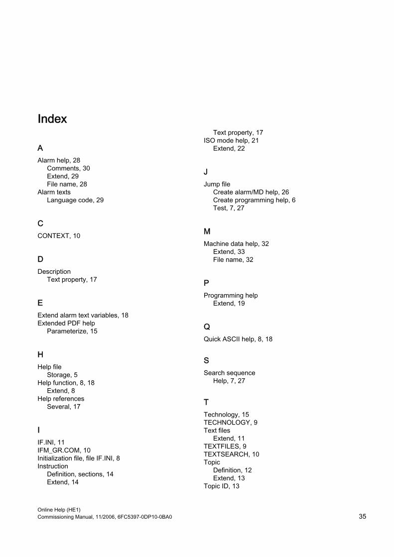
Online Help (HE1) Commissioning Manual, 11/2006, 6FC5397-0DP10-0BA0 35
Index
A Alarm help, 28
Comments, 30 Extend, 29 File name, 28
Alarm texts Language code, 29
C CONTEXT, 10
D Description
Text property, 17
E Extend alarm text variables, 18 Extended PDF help
Parameterize, 15
H Help file
Storage, 5 Help function, 8, 18
Extend, 8 Help references
Several, 17
I IF.INI, 11 IFM_GR.COM, 10 Initialization file, file IF.INI, 8 Instruction
Definition, sections, 14 Extend, 14
Text property, 17 ISO mode help, 21
Extend, 22
J Jump file
Create alarm/MD help, 26 Create programming help, 6 Test, 7, 27
M Machine data help, 32
Extend, 33 File name, 32
P Programming help
Extend, 19
Q Quick ASCII help, 8, 18
S Search sequence
Help, 7, 27
T Technology, 15 TECHNOLOGY, 9 Text files
Extend, 11 TEXTFILES, 9 TEXTSEARCH, 10 Topic
Definition, 12 Extend, 13
Topic ID, 13

Online Help (HE1) Commissioning Manual, 11/2006, 6FC5397-0DP10-0BA0 36

Introduction 1
Editing files with Word 2
Input of Text 3
Problems and remedies 4
References for text generation
5
SINUMERIK
SINUMERIK 840D sl/840Di sl/840D/840Di/810D Generating target language texts (TX2) Commissioning Manual
11/2006 6FC5397-0DP10-0BA0
Valid for: Controls SINUMERIK 840D sl/840DE sl SINUMERIK 840D powerline/840DE powerline SINUMERIK 840Di powerline/840DiE powerline SINUMERIK 810D powerline/810DE powerline Software Release: HMI Advanced V7.3 HMI Embedded V7.2

Safety Guidelines This manual contains notices you have to observe in order to ensure your personal safety, as well as to prevent damage to property. The notices referring to your personal safety are highlighted in the manual by a safety alert symbol, notices referring only to property damage have no safety alert symbol. These notices shown below are graded according to the degree of danger.
Danger
indicates that death or severe personal injury will result if proper precautions are not taken.
Warning
indicates that death or severe personal injury may result if proper precautions are not taken.
Caution
with a safety alert symbol, indicates that minor personal injury can result if proper precautions are not taken.
Caution
without a safety alert symbol, indicates that property damage can result if proper precautions are not taken.
Notice
indicates that an unintended result or situation can occur if the corresponding information is not taken into account.
If more than one degree of danger is present, the warning notice representing the highest degree of danger will be used. A notice warning of injury to persons with a safety alert symbol may also include a warning relating to property damage.
Qualified Personnel The device/system may only be set up and used in conjunction with this documentation. Commissioning and operation of a device/system may only be performed by qualified personnel. Within the context of the safety notes in this documentation qualified persons are defined as persons who are authorized to commission, ground and label devices, systems and circuits in accordance with established safety practices and standards.
Prescribed Usage Note the following:
Warning
This device may only be used for the applications described in the catalog or the technical description and only in connection with devices or components from other manufacturers which have been approved or recommended by Siemens. Correct, reliable operation of the product requires proper transport, storage, positioning and assembly as well as careful operation and maintenance.
Trademarks All names identified by ® are registered trademarks of the Siemens AG. The remaining trademarks in this publication may be trademarks whose use by third parties for their own purposes could violate the rights of the owner.
Disclaimer of Liability We have reviewed the contents of this publication to ensure consistency with the hardware and software described. Since variance cannot be precluded entirely, we cannot guarantee full consistency. However, the information in this publication is reviewed regularly and any necessary corrections are included in subsequent editions.
Siemens AG Automation and Drives Postfach 48 48 90437 NÜRNBERG GERMANY
Order No.: 6FC5397-0DP10-0BA0 Ⓟ 12/2006
Copyright © Siemens AG 2006. Technical data subject to change
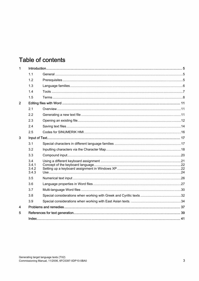
Generating target language texts (TX2) Commissioning Manual, 11/2006, 6FC5397-0DP10-0BA0 3
Table of contents 1 Introduction................................................................................................................................................ 5
1.1 General ..........................................................................................................................................5 1.2 Prerequisites ..................................................................................................................................5 1.3 Language families..........................................................................................................................6 1.4 Tools ..............................................................................................................................................7 1.5 Terms .............................................................................................................................................8
2 Editing files with Word ............................................................................................................................. 11 2.1 Overview ......................................................................................................................................11 2.2 Generating a new text file ............................................................................................................11 2.3 Opening an existing file................................................................................................................12 2.4 Saving text files............................................................................................................................14 2.5 Codes for SINUMERIK HMI.........................................................................................................16
3 Input of Text............................................................................................................................................. 17 3.1 Special characters in different language families ........................................................................17 3.2 Inputting characters via the Character Map.................................................................................18 3.3 Compound input...........................................................................................................................20 3.4 Using a different keyboard assignment .......................................................................................21 3.4.1 Concept of the keyboard language..............................................................................................22 3.4.2 Setting up a keyboard assignment in Windows XP .....................................................................22 3.4.3 Use...............................................................................................................................................24 3.5 Numerical text input .....................................................................................................................26 3.6 Language properties in Word files ...............................................................................................27 3.7 Multi-language Word files ............................................................................................................30 3.8 Special considerations when working with Greek and Cyrillic texts ............................................32 3.9 Special considerations when working with East Asian texts. ......................................................34
4 Problems and remedies........................................................................................................................... 37 5 References for text generation................................................................................................................. 39 Index........................................................................................................................................................ 41

Table of contents
Generating target language texts (TX2) 4 Commissioning Manual, 11/2006, 6FC5397-0DP10-0BA0
Tables
Table 1-1 Language families ......................................................................................................................... 6 Table 2-1 Encoding ..................................................................................................................................... 16 Table 3-1 Text file coding ............................................................................................................................ 19

Generating target language texts (TX2) Commissioning Manual, 11/2006, 6FC5397-0DP10-0BA0 5
Introduction 11.1 General
Since the 1990s, Microsoft have put considerable effort into satisfying global demands for information processing and software development. In addition to supporting as many languages as possible, one of the aims was to be able to support all languages with the same uniform operating system, as opposed to the language-specific versions of operating systems which were used before. As part of these efforts, many of the system components and applications were gradually converted to the cross-language platform Unicode. Although in many cases the user would have been completely unaware of this conversion process, in terms of the subjects discussed in this guide fundamentally different procedures need to be adopted depending on which version of the operating system is used. The procedure recommended for Windows 2000/XP is much simpler than the one recommended for Windows 95/NT4. Therefore it makes sense to change over to the new systems. The guide for older systems is no longer being updated by the documentation department.
1.2 Prerequisites
Supplementary conditions This document describes the procedure for generating a text with the following preconditions: • The text is to be generated on a Microsoft Windows operating system (Windows XP). • The text is to be generated in a language not identical to the language of the operating
system (= default language). • The present description uses German as the default language for all examples provided
herein. However, the described procedure will work just as well with a different language as the default Windows language.
• The text is to be generated in a format known as a "text file", i.e., a file which does not contain any formatting such as font type, font size, underlining, etc. This means that, apart from the text characters, the file will only contain ASCII control characters such as Tab, CR and LF (tab indent, carriage return and line feed).
• The language of the text requires a different Windows code page to that of the default language, i.e., the target language does not belong to the same language family as the default language.
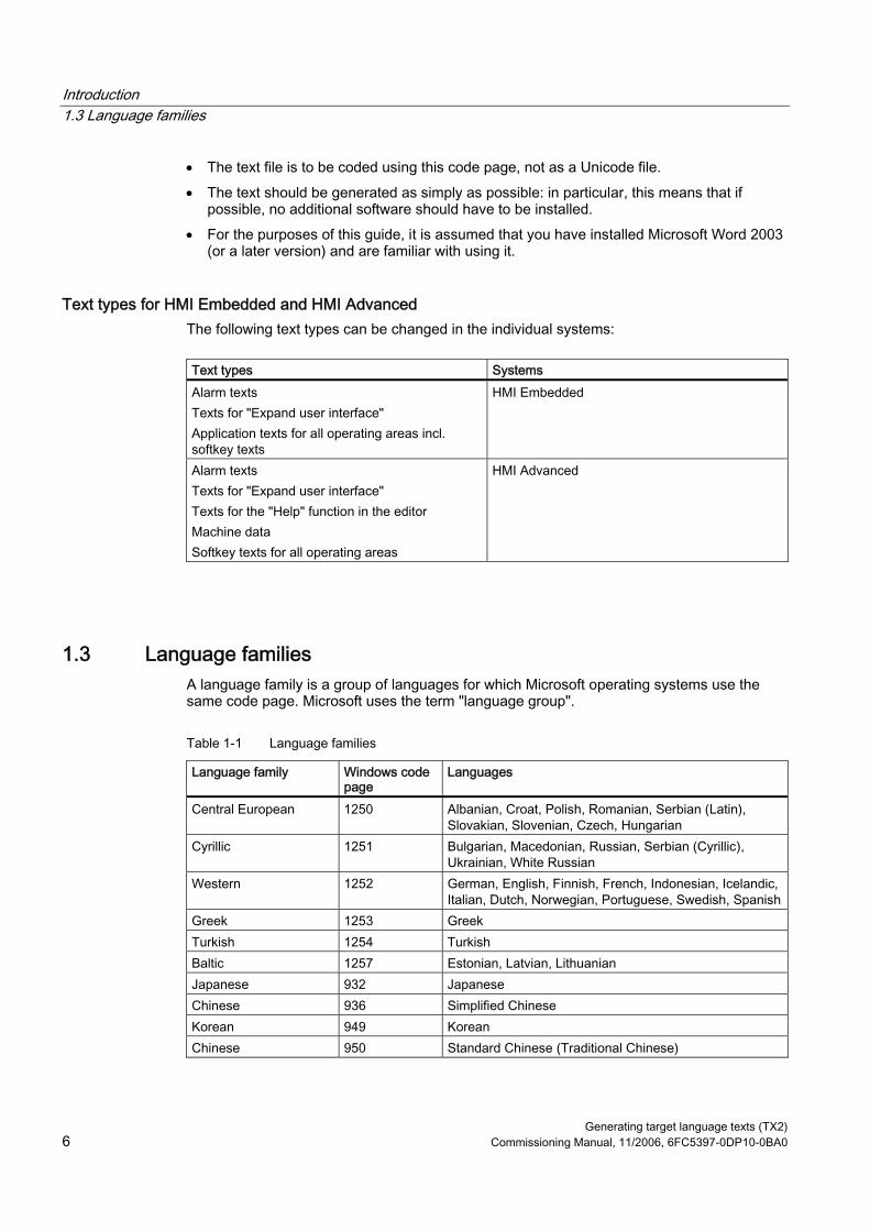
Introduction 1.3 Language families
Generating target language texts (TX2) 6 Commissioning Manual, 11/2006, 6FC5397-0DP10-0BA0
• The text file is to be coded using this code page, not as a Unicode file. • The text should be generated as simply as possible: in particular, this means that if
possible, no additional software should have to be installed. • For the purposes of this guide, it is assumed that you have installed Microsoft Word 2003
(or a later version) and are familiar with using it.
Text types for HMI Embedded and HMI Advanced The following text types can be changed in the individual systems:
Text types Systems Alarm texts Texts for "Expand user interface" Application texts for all operating areas incl. softkey texts
HMI Embedded
Alarm texts Texts for "Expand user interface" Texts for the "Help" function in the editor Machine data Softkey texts for all operating areas
HMI Advanced
1.3 Language families A language family is a group of languages for which Microsoft operating systems use the same code page. Microsoft uses the term "language group".
Table 1-1 Language families
Language family Windows code page
Languages
Central European 1250 Albanian, Croat, Polish, Romanian, Serbian (Latin), Slovakian, Slovenian, Czech, Hungarian
Cyrillic 1251 Bulgarian, Macedonian, Russian, Serbian (Cyrillic), Ukrainian, White Russian
Western 1252 German, English, Finnish, French, Indonesian, Icelandic, Italian, Dutch, Norwegian, Portuguese, Swedish, Spanish
Greek 1253 Greek Turkish 1254 Turkish Baltic 1257 Estonian, Latvian, Lithuanian Japanese 932 Japanese Chinese 936 Simplified Chinese Korean 949 Korean Chinese 950 Standard Chinese (Traditional Chinese)

Introduction 1.4 Tools
Generating target language texts (TX2) Commissioning Manual, 11/2006, 6FC5397-0DP10-0BA0 7
Operating system and target language from the same language family If the language of the operating system (e.g., German) belongs to the same language family as the target language (e.g., Portuguese), then some difficulties could possibly occur with the input of certain characters. However, there will be no problems displaying these characters with a simple text editor. Remedy: • Use the Windows "Character Map" tool
(see Section "Input via the Character Map") or • or switch the keyboard
(see Section "Using a different keyboard assignment") or • use the ALT+digit combination to enter these characterseinzelne Zeichen mit
ALT+Ziffernkombination eingeben (see Section "Numerical text input")
There should not be any further problems in this case. Use a simple text editor (e.g., Notepad) and save the texts in the usual way. Section "Files with Word 2003" does not apply.
Operating system and target language from different language families If the language of the operating system (e.g., German) does not belong to the same language family as the target language (e.g., Hungarian), difficulties will occur with both inputting and displaying the characters in a simple text editor (Notepad).
1.4 Tools
Standard version This document describes the use of Microsoft Word 2003 and other tools which may not necessarily be installed on your PC. You should have installed the following components: • Microsoft Word 2003 (required) • Windows XP: Language Support for East Asian characters (necessary for these
languages) • Windows XP: Character Map (recommended)
Checking the installation of the Language Support for East Asian languages To install the Language Support for East Asian languages, please refer to Section "Special considerations when working with East Asian languages".

Introduction 1.5 Terms
Generating target language texts (TX2) 8 Commissioning Manual, 11/2006, 6FC5397-0DP10-0BA0
1.5 Terms
Code page A list of characters which forms the character set for one or more languages. A code which is unique within this code page is assigned to each of the characters in the list. All of the code pages used in Windows share the ASCII range (codes 0 to 127). A distinction is made between single-byte code pages and multiple-byte code pages. In single-byte code pages (all European languages), each character is represented with a single byte. Accordingly, single-byte code pages comprise a maximum of 256 characters. Multiple-byte code pages (Asian languages) contain both characters which are stored as a single byte and characters which are stored with two (or more) bytes. The shared ASCII range is contained as a range of single-byte characters. There is a 1:1 assignment between Windows code page and language family. The language families are listed in Section "Language families".
Diacritical characters (diacritical = distinguishing) In most cases, a relatively small supplementary character, which is attached to a letter to give the letter a specific stress, a specific pronunciation or even a new meaning. Section "Special characters in different language families" contains a list of diacritical characters. If the combination of basic letters and diacritical characters belongs in a language-specific alphabet, this combination is contained in the appropriate Windows character sets (code page, Unicode) as a separate character.
Use of diacritical characters A diacritical character is used • To designate the combined character (e.g., Ģ = G cedilla, Õ = O tilde), • For the combined input, if there is no separate key that possesses the required combined
character (see Section "Using a different keyboard assignment"),
• In Vietnamese and Thai, for normal coding in text files, • For output (only in typographically compound texts): Diacritical characters and basic letter
are output separately, meaning that any combinations are possible, e.g., for ancient languages and phonetics.
In all the other cases, the combined letter is always considered as a compound unit. In some cases, however, the combined letter is incorrectly referred to as the diacritical character.

Introduction 1.5 Terms
Generating target language texts (TX2) Commissioning Manual, 11/2006, 6FC5397-0DP10-0BA0 9
Input Method Editor (IME) An aid for inputting the CJK characters (CJK: Abbreviation for Chinese, Japanese and Korean).
Language family A language family is a group of languages which uses the same code page. This requires the use of the same basic alphabet (e.g., Latin or Cyrillic), but it does not mean that the alphabet of all languages of this group is the same. There is a 1:1 assignment between Windows code page and language family. The language families are listed in Section "Language families".
Font files (TrueType fonts) Windows XP does not use font files that are stored separated for each code page; instead it uses something known as "Big Fonts", which are fonts that contain the character set for several code pages. saving memory capacity for the common characters. With Word 2003, the selection of characters from this total character set is performed via the Unicode coding, not via the code page coding. This makes it impossible to mix up characters with the same code in different code pages.
Default language The term "default language" is used in this guide for the language of the operating system, i.e., German for a German Windows environment and English for an English Windows environment.
Default keyboard setting Under "Control Panel" → "Regional and Language Options", in the tab "Languages", click under the heading "Text Services and Input languages" on the button "Details..." to reach the dialog box "Text Services and Input languages". Here you can see the default keyboard setting in the "Settings" tab under the heading "Default Language and Region Support". The default keyboard setting consists of a language property (left) and a keyboard assignment (right). This language property of the default keyboard setting need not absolutely match the default language.

Introduction 1.5 Terms
Generating target language texts (TX2) 10 Commissioning Manual, 11/2006, 6FC5397-0DP10-0BA0
Text file The term "Text file" is used to describe a file which does not contain any formatting (font type, font size, underscore, bold, italics etc.) or embedded objects (pictures, tables, graphics, footnotes etc.). This means that, apart from the text characters, the file will only contain ASCII control characters like Tab, CR and LF (tab indent, carriage return and line feed). The text characters are taken from a particular code page. Occasionally, text files are also incorrectly referred to as ASCII files. This is only correct if a text file only contains ASCII characters (codes 0 to 127) and is therefore code page invariant.
Unicode A 16-bit character set for which code pages are no longer required. All character codes are unique, without needing to specify the code page. Unicode programs like Word 2003 do not offer code page-dependent interpreting of characters and thus also cannot display characters differently by assigning a font or language property.
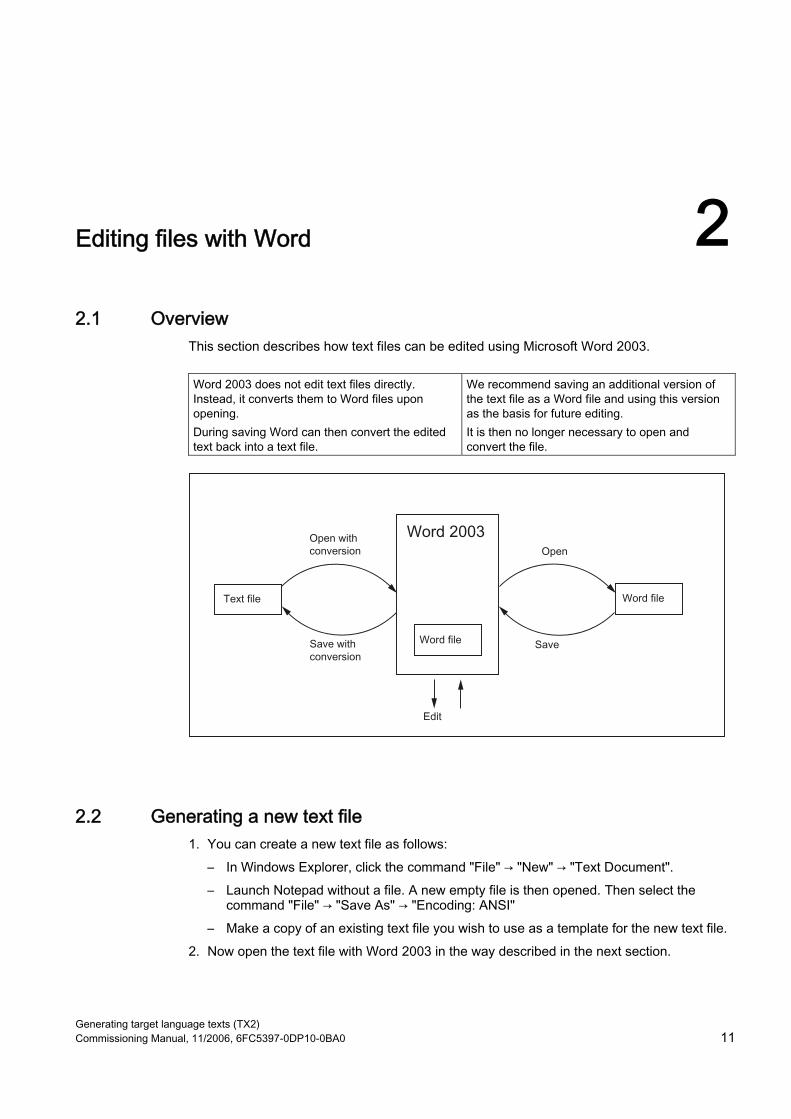
Generating target language texts (TX2) Commissioning Manual, 11/2006, 6FC5397-0DP10-0BA0 11
Editing files with Word 22.1 Overview
This section describes how text files can be edited using Microsoft Word 2003.
Word 2003 does not edit text files directly. Instead, it converts them to Word files upon opening. During saving Word can then convert the edited text back into a text file.
We recommend saving an additional version of the text file as a Word file and using this version as the basis for future editing. It is then no longer necessary to open and convert the file.
2.2 Generating a new text file 1. You can create a new text file as follows:
– In Windows Explorer, click the command "File" → "New" → "Text Document". – Launch Notepad without a file. A new empty file is then opened. Then select the
command "File" → "Save As" → "Encoding: ANSI" – Make a copy of an existing text file you wish to use as a template for the new text file.
2. Now open the text file with Word 2003 in the way described in the next section.

Editing files with Word 2.3 Opening an existing file
Generating target language texts (TX2) 12 Commissioning Manual, 11/2006, 6FC5397-0DP10-0BA0
2.3 Opening an existing file 1. In Word 2003, select "Open…" from the "File" menu. 2. From the "Open" dialog box, choose the "Text files" (*.txt)" setting under "Files of type".
If your file has a different extension from "txt", you must rename it.
3. Choose the file you would like to open and click "Open". Instead of steps 1-3, you can also use one of the standard shortcuts: – In Word you can use the list of the recently used files. – Drag and drop the text file from Explorer to the Word icon on your desktop. – If Word has already been launched, drag and drop the text file from Explorer to the
title bar of the Word window. 4. Note what happens next.
Continue with "Convert File" (see point 5.) if this dialog box opens. Continue with "File Conversion" (see point 6.) if this dialog box opens. If, however, the file is opened straightaway with neither the "Convert File" nor the "File Conversion" dialog boxes opening up, then Word has probably opened the file incorrectly under the assumption that the text has been written using the default language. Be careful with special characters. The special characters will appear incorrectly if the code page of the text file is not the same as the code page of the default language. In this case, go to "Extras" → "Options..." and open the Options dialog box for Word. Click "General" and select the option "Confirm conversion at Open". When this option is active the additional dialog box "Convert File" (see point 5.) will appear every time, but when the option is inactive it is skipped. Afterwards close the file and start again from point 1.

Editing files with Word 2.3 Opening an existing file
Generating target language texts (TX2) Commissioning Manual, 11/2006, 6FC5397-0DP10-0BA0 13
5. The "Convert File" dialog box will appear. Select "Encoded Text" and click "OK".
6. The "File Conversion - Example.txt" dialog box will then appear: – If "Windows (default)" is selected, activate "Other Encoding". Select the correct
encoding (Word will make a suggestion, which will not necessarily be correct).
– Section "Codes for SINUMERIK HMI", Table 2-1 lists the suitable encoding options. Check the preview area while doing this.

Editing files with Word 2.4 Saving text files
Generating target language texts (TX2) 14 Commissioning Manual, 11/2006, 6FC5397-0DP10-0BA0
7. Click "OK". The file is opened and converted to a Word file at the same time. The existing text is formatted using a default font.
2.4 Saving text files Save the text entered as a "Text File": 1. In Word, select "Save As…" from the "File" menu.
2. Choose the option "Text Only (*.txt)" under "Save as type". 3. Enter the name of the file in the "File name" box and click "Save".
– The "File Conversion" dialog box will then appear.
– Select the encoding which is suitable for your target language and click "OK". Section "Codes for SINUMERIK HMI", Table 2-1 lists the suitable encoding options.
– Your file is now saved as a text file and encoded using the selected code page in the process.
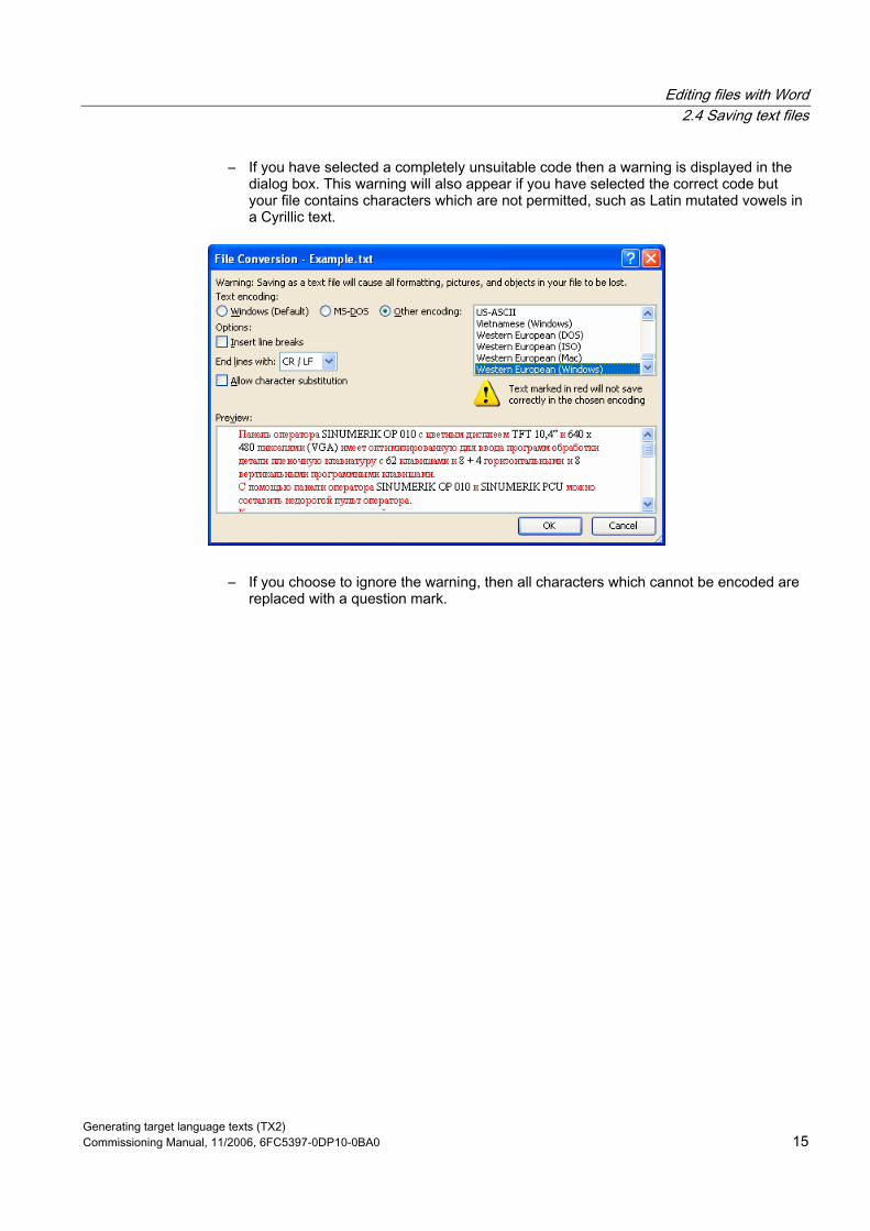
Editing files with Word 2.4 Saving text files
Generating target language texts (TX2) Commissioning Manual, 11/2006, 6FC5397-0DP10-0BA0 15
– If you have selected a completely unsuitable code then a warning is displayed in the dialog box. This warning will also appear if you have selected the correct code but your file contains characters which are not permitted, such as Latin mutated vowels in a Cyrillic text.
– If you choose to ignore the warning, then all characters which cannot be encoded are replaced with a question mark.
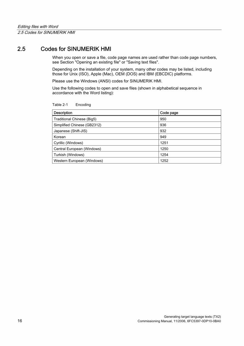
Editing files with Word 2.5 Codes for SINUMERIK HMI
Generating target language texts (TX2) 16 Commissioning Manual, 11/2006, 6FC5397-0DP10-0BA0
2.5 Codes for SINUMERIK HMI When you open or save a file, code page names are used rather than code page numbers, see Section "Opening an existing file" or "Saving text files". Depending on the installation of your system, many other codes may be listed, including those for Unix (ISO), Apple (Mac), OEM (DOS) and IBM (EBCDIC) platforms. Please use the Windows (ANSI) codes for SINUMERIK HMI. Use the following codes to open and save files (shown in alphabetical sequence in accordance with the Word listing):
Table 2-1 Encoding
Description Code page Traditional Chinese (Big5) 950 Simplified Chinese (GB2312) 936 Japanese (Shift-JIS) 932 Korean 949 Cyrillic (Windows) 1251 Central European (Windows) 1250 Turkish (Windows) 1254 Western European (Windows) 1252
Generating target language texts (TX2) Commissioning Manual, 11/2006, 6FC5397-0DP10-0BA0 17
Input of Text 33.1 Special characters in different language families
Latin language family With the Latin-based language families (Baltic, Central European, Turkish, Western), you can enter most of the characters, i.e., the basic Latin alphabet, directly with your (e.g., Western) keyboard. Most of the special characters, such as ĄáâåçđéèÍïŁŇñöőÓťŤůū, are made up of the Latin letters A-Z a-z and diacritical characters such as acute ', breve ˘, cedilla, circumflex (caret) ˆ, point ˙, colon (dieresis, trema) ¨, double-acute ˝, grave accent ', háček (caron) ˇ, macron ˉ, ogonek (nasal hook, crooked hook) ˛, squiggle ˚, slash /, hyphen – or tilde ˜. Other characters of the alphabet are special letters (Þþ, Ðð, ß) or ligatures (Ææ, Œœ, IJij). These are supplemented by language-specific abbreviations and punctuation marks, e.g., for the endings of the ordinal numbers in Spanish (ª and º) as well as the upside-down exclamation and interrogation marks (¡ and ¿). The input methods described in the following will apply without restrictions to the Latin-based language families.
Greek/Cyrillic language family Certain special considerations need to be taken into account when inputting texts using Greek or Cyrillic fonts. Read Section "Special considerations when working with Greek and Cyrillic texts" for additional information.
East Asian languages Certain special considerations also need to be taken into account when generating texts in Japanese, Chinese or Korean. Read Section "Special considerations when working with East Asian texts" for additional information.

Input of Text 3.2 Inputting characters via the Character Map
Generating target language texts (TX2) 18 Commissioning Manual, 11/2006, 6FC5397-0DP10-0BA0
Disruptive Word options Deactivate the following options in Word to prevent unwanted characters from reaching the text: In the dialog box "Tools" → "AutoCorrect Options" go to the "AutoFormat as you type" tab and under "Replace as you type" check: • "Straight quotes" with "Smart quotes" • English ordinals (1st) with superscript • Fractions (1/2) with fraction character (½) • Special characters (--) with symbols (—) "Apply as you type": • Automatic bulleted lists • Automatic numbered lists If you do leave any of the options active then you can always use Ctrl+Z to undo any automatic corrections. As a general rule this will give the same results as if the option was deactivated.
3.2 Inputting characters via the Character Map
Note The Character Map integrated in Word (menu commands "Insert" → "Symbol...") is not suitable for generating code page-encoded text files, as it cannot be limited to the relevant code page. Use the "Character Map" system program as described below.
Selecting the Character Map 1. In the start menu:
select "Programs" → "Accessories" → "System Tools" → "Character Map" to start the "Character Map" tool.
2. From "Font", choose the same font type as you have selected for the text file.

Input of Text 3.2 Inputting characters via the Character Map
Generating target language texts (TX2) Commissioning Manual, 11/2006, 6FC5397-0DP10-0BA0 19
3. Activate the box "Advanced view". 4. Under "Character set" select the code page for your text file in order to restrict the
number of available characters to this code page. The code pages are referred to as follows:
Table 3-1 Text file coding
Description Code page Windows: Chinese (Taiwan) 950 Windows: Chinese (PROC) 936 Windows: Japanese 932 Windows: Korean 949 Windows: Cyrillic 1251 Windows: Eastern European 1250 Windows: Turkish 1254 Windows: Western 1252

Input of Text 3.3 Compound input
Generating target language texts (TX2) 20 Commissioning Manual, 11/2006, 6FC5397-0DP10-0BA0
Inputting characters 1. Choose a character you want to input.
The information bar at the bottom will display the Unicode code (U+..., hexadecimal), the code page code (in brackets) and the clear text description of the character. If you have set up the keyboard assignment accordingly (see Section "Using a different keyboard assignment"), the keystroke combination for entering the character numerically will appear at the bottom right in the status bar (see Section "Numerical text input").
2. Click "Select". The character is copied into the "Characters to copy" field.
3. Repeat steps 1 and 2 for further characters. 4. After you have selected all the characters, click "Copy".
The characters are copied from the "Characters to copy" field to the clipboard. 5. Switch back to Word and press Ctrl-V.
The character is copied from the clipboard to the text.
3.3 Compound input With many of the compound special characters it is possible to input the diacritical character first and then the letter. The diacritical character will not appear at first and is then combined with the letter to form a special character.
Example With a German keyboard assignment, press, for example, the keys ' (acute) and "a" one after the other to obtain the character á (a-acute). The keys with the diacritical characters, which are thus dealt with in a special way, are marked with a special color in the descriptions of the keyboard assignments.

Input of Text 3.4 Using a different keyboard assignment
Generating target language texts (TX2) Commissioning Manual, 11/2006, 6FC5397-0DP10-0BA0 21
Keyboard assignments The table below shows some keyboard assignments for the supported diacritical characters:
Acute Grave Circum-
flex Há-ček
Breve Ogon-ek
Point Colon Ce-dilla
Double acute
Squig-gle
Tilde Keyboard assignments
' ' ˆ ˇ ˘ ˛ ˙ ¨ ¸ ˝ ˚ ˜ German X X X French X X X X Polish X X X X X X X X X X Spanish X X X X X Czech X X X X X X X X X X Hungarian X X X X X X X X X U.S. International X X X X X
Obtain a graphical representation of your keyboard assignment to learn which key combinations produce the diacritical characters.
Keyboard assignment in picture form Images of the keyboard assignments can be obtained from Microsoft via the Internet at the following address: http://www.microsoft.com/globaldev/reference/keyboards.mspx If you press the space bar after the diacritical character, you will see the character itself.
Note It can be useful to switch the keyboard assignment to "U.S. International" which corresponds mainly to the American keyboard, but additionally contains 5 diacritical characters and provides many special characters.
3.4 Using a different keyboard assignment
Necessity of changing the keyboard assignment When is a change in the keyboard assignment necessary? • If you have to input a lot of text. • Your translator, who is used to a certain language-specific keyboard, wants to use your
PC. However, if you (as a German) only need to make smaller changes to existing files, then the German keyboard assignment may be enough, provided there are only a few special characters which cannot be represented with the German keyboard. You can enter these characters using the Character Map.
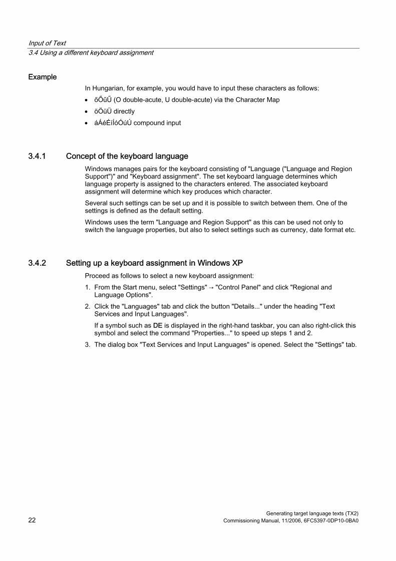
Input of Text 3.4 Using a different keyboard assignment
Generating target language texts (TX2) 22 Commissioning Manual, 11/2006, 6FC5397-0DP10-0BA0
Example In Hungarian, for example, you would have to input these characters as follows: • őŐűŰ (O double-acute, U double-acute) via the Character Map • öÖüÜ directly • áÁéÉíÍóÓúÚ compound input
3.4.1 Concept of the keyboard language Windows manages pairs for the keyboard consisting of "Language ("Language and Region Support")" and "Keyboard assignment". The set keyboard language determines which language property is assigned to the characters entered. The associated keyboard assignment will determine which key produces which character. Several such settings can be set up and it is possible to switch between them. One of the settings is defined as the default setting. Windows uses the term "Language and Region Support" as this can be used not only to switch the language properties, but also to select settings such as currency, date format etc.
3.4.2 Setting up a keyboard assignment in Windows XP Proceed as follows to select a new keyboard assignment: 1. From the Start menu, select "Settings" → "Control Panel" and click "Regional and
Language Options". 2. Click the "Languages" tab and click the button "Details..." under the heading "Text
Services and Input Languages". If a symbol such as DE is displayed in the right-hand taskbar, you can also right-click this symbol and select the command "Properties..." to speed up steps 1 and 2.
3. The dialog box "Text Services and Input Languages" is opened. Select the "Settings" tab.

Input of Text 3.4 Using a different keyboard assignment
Generating target language texts (TX2) Commissioning Manual, 11/2006, 6FC5397-0DP10-0BA0 23
4. Click "Add". The dialog box "Add Language and Region Support" is opened.
5. In the dialog box "Add Language and Region Support", select a language under "Language and Region Support" and the associated keyboard assignment under "Keyboard Assignment". The language ("Language and Region Support") may also be the same as the default language or as some other language for which you have already set up a keyboard assignment. However, in this case you will not be able to make such a good distinction between the two keyboard assignments, as Windows usually only displays the language ("Language and Region Support").
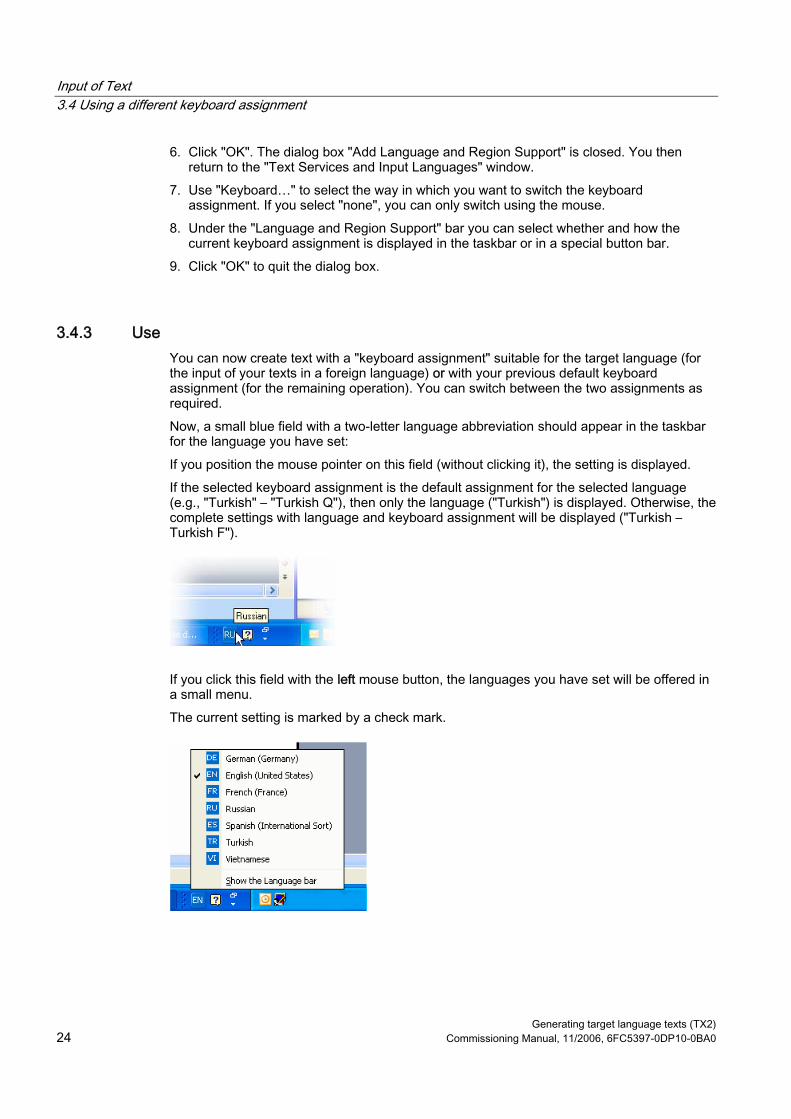
Input of Text 3.4 Using a different keyboard assignment
Generating target language texts (TX2) 24 Commissioning Manual, 11/2006, 6FC5397-0DP10-0BA0
6. Click "OK". The dialog box "Add Language and Region Support" is closed. You then return to the "Text Services and Input Languages" window.
7. Use "Keyboard…" to select the way in which you want to switch the keyboard assignment. If you select "none", you can only switch using the mouse.
8. Under the "Language and Region Support" bar you can select whether and how the current keyboard assignment is displayed in the taskbar or in a special button bar.
9. Click "OK" to quit the dialog box.
3.4.3 Use You can now create text with a "keyboard assignment" suitable for the target language (for the input of your texts in a foreign language) or with your previous default keyboard assignment (for the remaining operation). You can switch between the two assignments as required. Now, a small blue field with a two-letter language abbreviation should appear in the taskbar for the language you have set: If you position the mouse pointer on this field (without clicking it), the setting is displayed. If the selected keyboard assignment is the default assignment for the selected language (e.g., "Turkish" – "Turkish Q"), then only the language ("Turkish") is displayed. Otherwise, the complete settings with language and keyboard assignment will be displayed ("Turkish – Turkish F").
If you click this field with the left mouse button, the languages you have set will be offered in a small menu. The current setting is marked by a check mark.
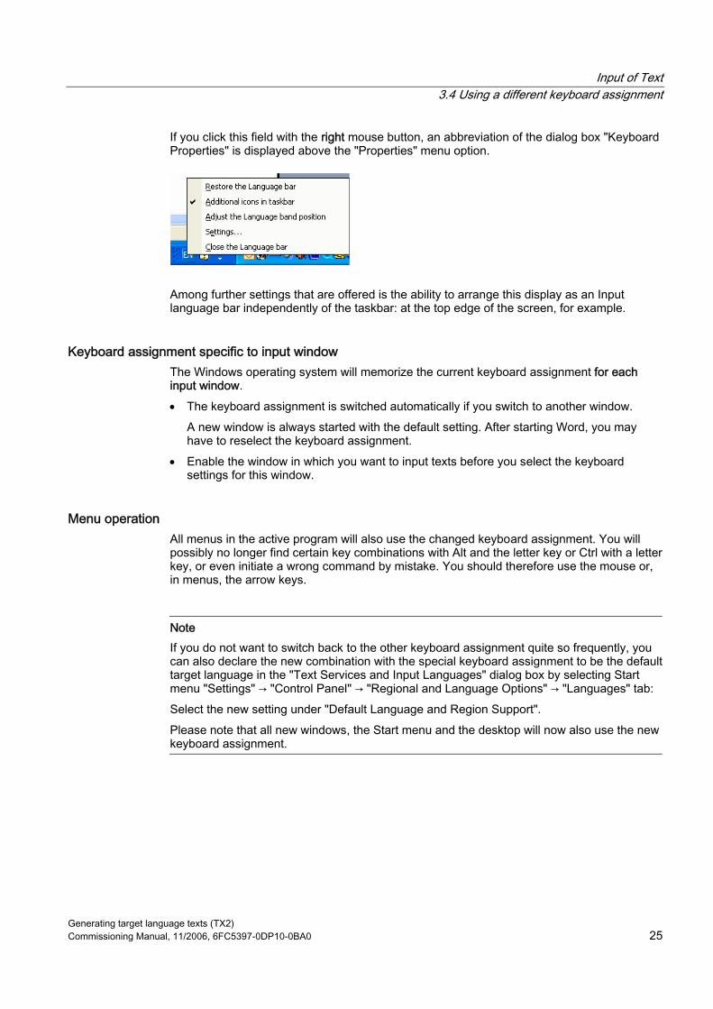
Input of Text 3.4 Using a different keyboard assignment
Generating target language texts (TX2) Commissioning Manual, 11/2006, 6FC5397-0DP10-0BA0 25
If you click this field with the right mouse button, an abbreviation of the dialog box "Keyboard Properties" is displayed above the "Properties" menu option.
Among further settings that are offered is the ability to arrange this display as an Input language bar independently of the taskbar: at the top edge of the screen, for example.
Keyboard assignment specific to input window The Windows operating system will memorize the current keyboard assignment for each input window. • The keyboard assignment is switched automatically if you switch to another window.
A new window is always started with the default setting. After starting Word, you may have to reselect the keyboard assignment.
• Enable the window in which you want to input texts before you select the keyboard settings for this window.
Menu operation All menus in the active program will also use the changed keyboard assignment. You will possibly no longer find certain key combinations with Alt and the letter key or Ctrl with a letter key, or even initiate a wrong command by mistake. You should therefore use the mouse or, in menus, the arrow keys.
Note If you do not want to switch back to the other keyboard assignment quite so frequently, you can also declare the new combination with the special keyboard assignment to be the default target language in the "Text Services and Input Languages" dialog box by selecting Start menu "Settings" → "Control Panel" → "Regional and Language Options" → "Languages" tab: Select the new setting under "Default Language and Region Support". Please note that all new windows, the Start menu and the desktop will now also use the new keyboard assignment.

Input of Text 3.5 Numerical text input
Generating target language texts (TX2) 26 Commissioning Manual, 11/2006, 6FC5397-0DP10-0BA0
Keyboard assignment in picture form You can obtain the keyboard assignment in picture form. For appropriate Internet addresses, see Section "References for text generation"
Checking the keyboard assignment Compare the keyboard assignment and note a key with two different assignments. If you are not sure, press this key when inputting the text to test which assignment is active. Example: If the German keyboard assignment is active, pressing key "1" (letter group) will produce a "1" and if the Czech keyboard assignment is active, a "+".
Note Check whether the automatic option for switching over the keyboard has been activated in Word. Inadvertent switching of the keyboard assignment by Word can cause confusion. Section "Multi-language Word files" describes situations in which the automatic keyboard switching function is useful and how to activate and deactivate it.
3.5 Numerical text input You can only use numerical input with Word if you have selected a suitable keyboard assignment (see Section "Using a different keyboard assignment"). Press the ALT key, and while holding down the key, enter zero and then the three-digit decimal coding of the desired special character on the numerical key group. Only then release the ALT key. Example (Turkish): ALT+0222 results in Ş (S with cedilla). To produce this character, you will only need the Character Map of the appropriate code page (see Section "Language families"). Section "Input via the Character Map" also describes where the key combination is displayed in the "Character Map" tool.
Overview tables of the code pages You will find overview tables of the code pages at, e.g., Microsoft under: http://www.microsoft.com/globaldev/reference/WinCP.mspx From these tables, combine the headers for the column and row (hexadecimal 00 to FF) and convert this number to form a decimal number (0 to 255). The 4-digit hexadecimal numbers contained in the individual table fields are the corresponding Unicode codes which can be used for identification of a character, but they cannot be used for numerical input of that character.

Input of Text 3.6 Language properties in Word files
Generating target language texts (TX2) Commissioning Manual, 11/2006, 6FC5397-0DP10-0BA0 27
3.6 Language properties in Word files
Language property The language is a property (attribute) that is managed separately in Word for each character, in the same way as other text properties (bold, underline, etc.): • In the language properties, Word will remember the language to which the character, the
character sequence, the word or the whole sentence belongs. • The language property is independent of the font. For example, a Cyrillic character can
possess the language property "German". • The language property is managed internally as a combination of main language and
sublanguage, e.g., "French (Canada)". Microsoft sometimes uses the designation "Region scheme" for the language property: this term also covers properties such as currency, date format, decimal separators etc.
Effects of the language property This property is used (evaluated) for the spell checker and for automatic keyboard switching (see Section "Multi-language Word files"). If you do not wish to use either the spell checker or the automatic keyboard switching function, there is generally no need to worry about the language properties. In this case, do not forget to deactivate the automatic keyboard switching function.
Saving the language property Microsoft Word saves this property in Word files (*.doc). If a document is saved as a text file (*.txt) then this property is lost along with the other text properties. If you wish to use the language property, it therefore makes sense to use a Word file to edit the texts and to keep it for subsequent changes. Whenever you reach a stage where you want to stop editing, you can save the document as a text file following the procedure described in Section "Saving text files".
Displaying the language property In Word, the current language property is displayed in the status bar at the bottom edge of the window.

Input of Text 3.6 Language properties in Word files
Generating target language texts (TX2) 28 Commissioning Manual, 11/2006, 6FC5397-0DP10-0BA0
Setting the language property Proceed as follows to set the language property for a text: 1. Highlight the part of the text for which you wish to set the language property, or press
CTRL+A to select the entire text. 2. Then select the command "Extras" → "Language" → "Set Language...". 3. In the "Language" dialog box you can choose the correct language. Click "OK" when you
are done.
Quick setting of the language property In Word, you can insert a combined display and selection box into a symbol bar. This both displays the current language property and enables you to set the language as well. Proceed as follows to insert this field into a symbol bar: 1. In the "Extras" menu, select the command "Customize..."
2. In the "Customize" dialog box select the "Commands" tab. 3. Select "Tools" from the list of categories on the left. 4. Then select "Language" from the list of commands on the right (see Fig.). 5. Drag and drop this entry with the left mouse button into a symbol bar.
6. Close the dialog box. With this selection box, you can then change the selected language for any part of the text.
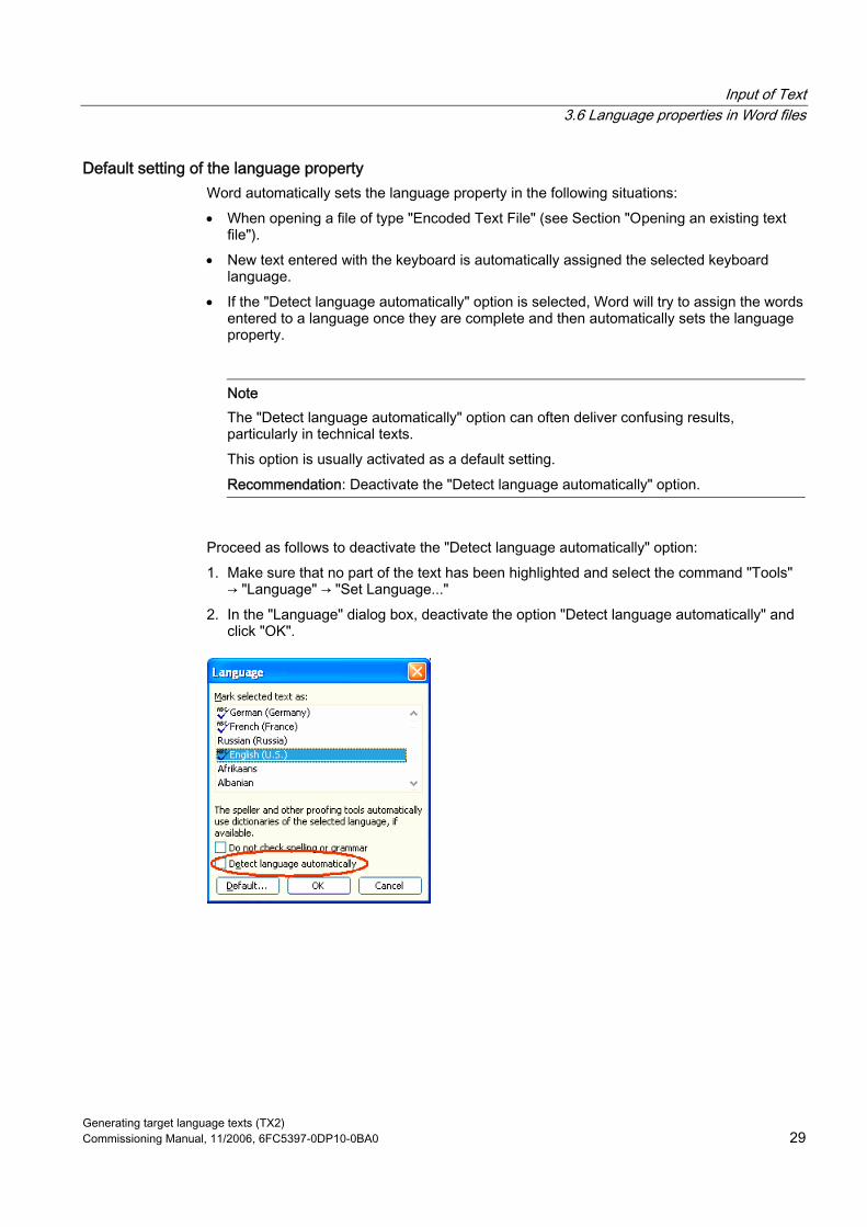
Input of Text 3.6 Language properties in Word files
Generating target language texts (TX2) Commissioning Manual, 11/2006, 6FC5397-0DP10-0BA0 29
Default setting of the language property Word automatically sets the language property in the following situations: • When opening a file of type "Encoded Text File" (see Section "Opening an existing text
file"). • New text entered with the keyboard is automatically assigned the selected keyboard
language. • If the "Detect language automatically" option is selected, Word will try to assign the words
entered to a language once they are complete and then automatically sets the language property.
Note The "Detect language automatically" option can often deliver confusing results, particularly in technical texts. This option is usually activated as a default setting. Recommendation: Deactivate the "Detect language automatically" option.
Proceed as follows to deactivate the "Detect language automatically" option: 1. Make sure that no part of the text has been highlighted and select the command "Tools"
→ "Language" → "Set Language..." 2. In the "Language" dialog box, deactivate the option "Detect language automatically" and
click "OK".

Input of Text 3.7 Multi-language Word files
Generating target language texts (TX2) 30 Commissioning Manual, 11/2006, 6FC5397-0DP10-0BA0
3.7 Multi-language Word files In certain cases it may be useful to deliberately set different language properties for different parts of the text in a Word file.
Supplementary conditions for multi-language Word files You want to enter certain parts of the text with the German keyboard assignment and then also edit these parts later on with the German keyboard assignment, whereas other parts of the text are to be generated and edited with the keyboard assignment of the target language.
Table with two language properties To generate a multi-column text in which, for example, the first column possesses the language property "German" and the second column "Russian", for example, you can proceed as follows: • Switch to the German keyboard and enter the first column of the first line. Then switch to
the Russian keyboard and enter the second column: [Text 103][Mode 28] "йцукенгшщзхъфывапролджэячсмить"
• This does not need to be a Word table with borders and fields. You can also use a simple line and separate the different parts with spaces.
• Select the whole line, copy this to the clipboard by using Ctrl-C and paste this line several times by pressing Ctrl-V. This will give you two columns with German on the left and Russian on the right.
[Text 103][Mode 28] "йцукенгшщзхъфывапролджэячсмить" [Text 103][Mode 28] "йцукенгшщзхъфывапролджэячсмить" [Text 103][Mode 28] "йцукенгшщзхъфывапролджэячсмить" [Text 103][Mode 28] "йцукенгшщзхъфывапролджэячсмить" [Text 103][Mode 28] "йцукенгшщзхъфывапролджэячсмить" [Text 103][Mode 28] "йцукенгшщзхъфывапролджэячсмить"
Examples This can be necessary in the following cases: • With Greek and Cyrillic texts, the Latin letters and other ASCII characters are missing in
the appropriate keyboard assignments. • With some keyboard assignments such as Czech, no access to the digits is granted on
the standard keyboard level. • The arrangement of the Latin letters deviates substantially from the arrangement to which
you are accustomed (e.g., Turkish-F keyboard assignment). • You, as a German, want to prepare one part of the text, and a second part is to be
generated by your translator.
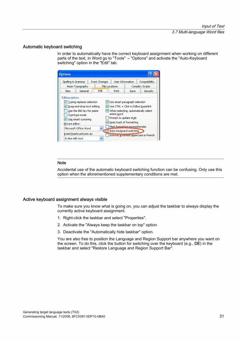
Input of Text 3.7 Multi-language Word files
Generating target language texts (TX2) Commissioning Manual, 11/2006, 6FC5397-0DP10-0BA0 31
Automatic keyboard switching In order to automatically have the correct keyboard assignment when working on different parts of the text, in Word go to "Tools" → "Options" and activate the "Auto-Keyboard switching" option in the "Edit" tab.
Note Accidental use of the automatic keyboard switching function can be confusing. Only use this option when the aforementioned supplementary conditions are met.
Active keyboard assignment always visible To make sure you know what is going on, you can adjust the taskbar to always display the currently active keyboard assignment. 1. Right-click the taskbar and select "Properties". 2. Activate the "Always keep the taskbar on top" option. 3. Deactivate the "Automatically hide taskbar" option. You are also free to position the Language and Region Support bar anywhere you want on the screen. To do this, click the button for switching over the keyboard (e.g., DE) in the taskbar and select "Restore Language and Region Support Bar".
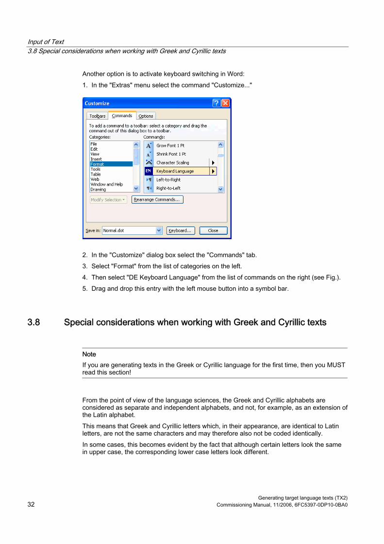
Input of Text 3.8 Special considerations when working with Greek and Cyrillic texts
Generating target language texts (TX2) 32 Commissioning Manual, 11/2006, 6FC5397-0DP10-0BA0
Another option is to activate keyboard switching in Word: 1. In the "Extras" menu select the command "Customize..."
2. In the "Customize" dialog box select the "Commands" tab. 3. Select "Format" from the list of categories on the left. 4. Then select "DE Keyboard Language" from the list of commands on the right (see Fig.). 5. Drag and drop this entry with the left mouse button into a symbol bar.
3.8 Special considerations when working with Greek and Cyrillic texts
Note If you are generating texts in the Greek or Cyrillic language for the first time, then you MUST read this section!
From the point of view of the language sciences, the Greek and Cyrillic alphabets are considered as separate and independent alphabets, and not, for example, as an extension of the Latin alphabet. This means that Greek and Cyrillic letters which, in their appearance, are identical to Latin letters, are not the same characters and may therefore also not be coded identically. In some cases, this becomes evident by the fact that although certain letters look the same in upper case, the corresponding lower case letters look different.

Input of Text 3.8 Special considerations when working with Greek and Cyrillic texts
Generating target language texts (TX2) Commissioning Manual, 11/2006, 6FC5397-0DP10-0BA0 33
Font Name Meaning Latin P, p Latin letter P Greek Ρ, ρ Greek letter RHO Cyrillic Р, р Cyrillic letter ER Latin H, h Latin letter H Greek Η, η Greek letter ETA Cyrillic Н, н Cyrillic letter EN
Example Incorrect coding could have the following consequences: Let us suppose that you wrote the Russian word for "NO" ("HET") using Latin letters instead of "HET" using Cyrillic letters. Initially you would see no difference. However, a search for "нет" in lower case letters with the search option "Ignore uppercase/lowercase letters" would not find the incorrectly coded spelling.
Keyboard assignment for Greek/Cyrillic font For this reason, the keyboard assignments for the Greek and Cyrillic fonts have been designed in such a way that the Latin letters are not available at all, not even via AltGr key combinations. These keyboard assignments have normally only two levels (standard and SHIFT).
Keyboard assignment for the Russian font In the Russian keyboard assignment, there are also some ASCII special characters which are missing, such as #$[]{}"|~&. For these languages it makes sense, therefore, to use Word files with two languages, as described in Section "Multi-language Word files".
Note • Switch the keyboard to Latin only if this is absolutely necessary! When doing so, do not
switch over for individual letters, but only for complete words and sentences. Never use words with mixed codings!
• Find out whether and to what extent certain German, English or international abbreviations (e.g. DIN/ISO) may or must be written using Latin fonts, or whether a conversion (ДИН/ИСО) is more appropriate, according to the conventions of the country in question. The key assignment for combinations, such as Ctrl-C, Ctrl-V, Ctrl-Z, Alt-A, etc. normally follow the US keyboard assignment.

Input of Text 3.9 Special considerations when working with East Asian texts.
Generating target language texts (TX2) 34 Commissioning Manual, 11/2006, 6FC5397-0DP10-0BA0
3.9 Special considerations when working with East Asian texts.
Requirement To author or correct texts in Japanese, Chinese or Korean, you will need to have installed the corresponding expansion package for the operating system.
Checking the system installation Open the dialog box "Regional and Language Options" via "Start" → "Settings" → "Control Panel". Check the "Languages" tab to see whether the option "Install files for East Asian languages" has been selected.
You will not usually need the installation CD to reinstall the files for East Asian languages in Windows XP, as the files are already present on the hard drive in compressed form. You will, however, require Administrator Rights to perform the installation.
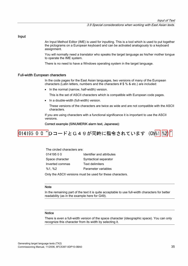
Input of Text 3.9 Special considerations when working with East Asian texts.
Generating target language texts (TX2) Commissioning Manual, 11/2006, 6FC5397-0DP10-0BA0 35
Input An Input Method Editor (IME) is used for inputting. This is a tool which is used to put together the pictograms on a European keyboard and can be activated analogously to a keyboard assignment. You will normally need a translator who speaks the target language as his/her mother tongue to operate the IME system. There is no need to have a Windows operating system in the target language.
Full-width European characters In the code pages for the East Asian languages, two versions of many of the European characters (Latin letters, numbers and the characters # $ % & etc.) are included: • In the normal (narrow, half-width) version.
This is the set of ASCII characters which is compatible with European code pages. • In a double-width (full-width) version.
These versions of the characters are twice as wide and are not compatible with the ASCII characters.
If you are using characters with a functional significance it is important to use the ASCII versions. Correct example (SINUMERIK alarm text, Japanese):
The circled characters are: 014195 0 0 Identifier and attributes Space character Syntactical separator Inverted commas Text delimiters %1, %2 Parameter variables
Only the ASCII versions must be used for these characters.
Note In the remaining part of the text it is quite acceptable to use full-width characters for better readability (as in the example here for G49).
Notice There is even a full-width version of the space character (ideographic space). You can only recognize this character from its width by selecting it.
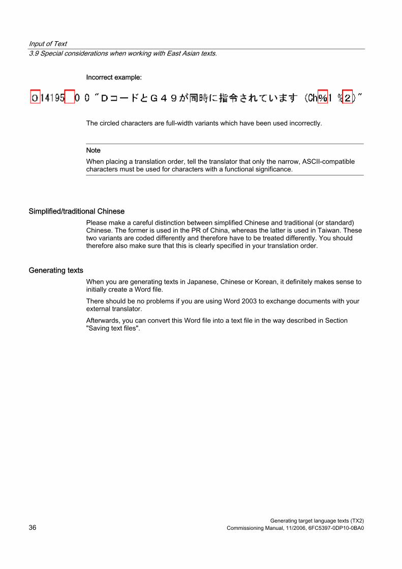
Input of Text 3.9 Special considerations when working with East Asian texts.
Generating target language texts (TX2) 36 Commissioning Manual, 11/2006, 6FC5397-0DP10-0BA0
Incorrect example:
The circled characters are full-width variants which have been used incorrectly.
Note When placing a translation order, tell the translator that only the narrow, ASCII-compatible characters must be used for characters with a functional significance.
Simplified/traditional Chinese Please make a careful distinction between simplified Chinese and traditional (or standard) Chinese. The former is used in the PR of China, whereas the latter is used in Taiwan. These two variants are coded differently and therefore have to be treated differently. You should therefore also make sure that this is clearly specified in your translation order.
Generating texts When you are generating texts in Japanese, Chinese or Korean, it definitely makes sense to initially create a Word file. There should be no problems if you are using Word 2003 to exchange documents with your external translator. Afterwards, you can convert this Word file into a text file in the way described in Section "Saving text files".

Generating target language texts (TX2) Commissioning Manual, 11/2006, 6FC5397-0DP10-0BA0 37
Problems and remedies 4Keyboard assignment switches unintentionally
Problem: The keyboard occasionally switches to a different assignment while text is being entered, without this being explicitly requested. Remedy: Check whether the option for automatic keyboard switching is set as described in Section "Multi-language Word files". Deactivate this option.
Language properties are changed inadvertently Problem: After creating a text with certain keyboard assignments (e.g., Polish), you notice that parts of the text have German or English as the language property. Remedy: Deactivate the automatic language recognition option as described in Section "Language properties in Word files".
Hotkeys no longer work Problem: Certain commands (Ctrl+C, Alt+T etc.) no longer work. Remedy: As a result of a different keyboard assignment, the keyboard shortcuts for certain commands have changed. Use the mouse while you are working with the other keyboard assignment.

Problems and remedies
Generating target language texts (TX2) 38 Commissioning Manual, 11/2006, 6FC5397-0DP10-0BA0
Individual texts not working Problem: In some cases, the finished text files do not work in the SINUMERIK Runtime system. Individual texts or lines of text are obviously not being read correctly. Remedy: Check the formal text criteria: Are all of the characters which have a functional significance correctly encoded? • If inverted commas are a requirement, check whether Word has converted the straight
inverted commas (ASCII characters) that were entered into typographical inverted commas. Some disruptive Word options are listed in Section "Special characters in different language families".
• If the texts in question are East Asian texts, check the coding of the non-Asian characters. See Section "Special considerations when working with East Asian texts". If full-width characters have been used for functional characters, replace them with the corresponding ASCII variants.
Yen character (Japanese) or Won character (Korean) in the text Problem: The translator has obviously used a Yen character ¥ or a Won character W wherever you would expect a backslash “\”. Remedy: This is not necessarily a mistake. Instead, this has historic reasons. For many years the Yen character has been used in Japan and the Won character in Korea in place of the backslash character. This representation was kept once the PC users in those countries had got used to using this representation in path names (where you would otherwise expect the backslash character). However, internally this is still the backslash character. In the fonts "MS Gothic" (Japanese) and "Batang" (Korean) the backslash symbol is represented as a currency character. However, it is also possible that the Yen character (Unicode U+00A5) or Won character (Unicode U+20A9) was actually entered instead of the backslash character (Unicode U+005C). To check this, proceed as follows: 1. Reformat the text in Word using a different font, e.g., "Courier New". If you see the
backslash character in its normal representation, there are no problems. 2. However, if you can still see the currency symbol or a symbol which is not a valid symbol,
you should correct the character and replace it with a backslash. 3. Afterwards, revert back to the normal font (MS Gothic or Batang).

Generating target language texts (TX2) Commissioning Manual, 11/2006, 6FC5397-0DP10-0BA0 39
References for text generation 5For further information about generating texts, please refer to: • Book: Developing International Software, Second Edition
Microsoft Press, October 2002, ISBN 0-7356-1583-7 http://www.microsoft.com/globaldev/getwr/dis_v2/default.mspx
• Overview tables of the Microsoft code pages http://www.microsoft.com/globaldev/reference/WinCP.mspx
• Pictures of the keyboard assignments in Microsoft can be found at the following address: http://www.microsoft.com/globaldev/reference/keyboards.mspx
• Windows XP FAQs: http://www.microsoft.com/globaldev/DrIntl/faqs/winxp.mspx
• Microsoft Global Software Development Detailed explanations on various aspects of international software http://www.microsoft.com/globaldev
• Unicode Tables, definitions, standards and tools http://www.unicode.org

References for text generation
Generating target language texts (TX2) 40 Commissioning Manual, 11/2006, 6FC5397-0DP10-0BA0

Generating target language texts (TX2) Commissioning Manual, 11/2006, 6FC5397-0DP10-0BA0 41
Index
C Character Map
Code page, 19 Input, 18 Inputting characters, 19 Select, 18
Checking the installation, 7 Chinese (simplified), 36 Chinese (traditional), 36 CJK characters, 9 Code page, 8
Description, 15 Number, 15
Cyrillic language family, 32
D Diacritical characters
Application, 8 Concept, 8 Overview, 17
E East Asian texts, 34
F File conversion, 13
G Greek/Cyrillic language family, 32
I IME (Input Method Editor), 9 Input Method Editor (IME), 9
K keyboard assignment
Changing, 21 Keyboard assignment
Always visible, 31 in picture form, 21 In picture form, 25 Set up in Windows XP, 22
Keyboard assignments Specific to input window, 24
Keyboard setting Default, 9
Keyboard switching Automatic, 30
L Language family, 9
Overview, 6 Language group, 6 language property
Set, 27 Language property
Quick setting, 27 Table with two language properties, 29
M Multi-language Word files, 29
S Special characters in different language families, 17 System installation
On Windows XP, 34
T text file
Convert, 13 Generate new, 11

Index
Generating target language texts (TX2) 42 Commissioning Manual, 11/2006, 6FC5397-0DP10-0BA0
Open, 12 Save, 14
Text input Numerical, 25
TrueType fonts, 9
U Unicode, 10
W Windows code page, 6 Word files
Multi-language, 29

Commissioning a system 1
Configuring the system 2
Install software and updates 3
Backing up and restoring data
4
Service and diagnostics 5
List of Abbreviations A
SINUMERIK 840Di sl/840D sl SINUMERIK 810D/840D PCU Basesoftware V8.0
Commissioning Manual
07/2006 6FC5397-0DP10-0BA0

Safety Guidelines This manual contains notices you have to observe in order to ensure your personal safety, as well as to prevent damage to property. The notices referring to your personal safety are highlighted in the manual by a safety alert symbol, notices referring only to property damage have no safety alert symbol. These notices shown below are graded according to the degree of danger.
Danger
indicates that death or severe personal injury will result if proper precautions are not taken.
Warning
indicates that death or severe personal injury may result if proper precautions are not taken.
Caution
with a safety alert symbol, indicates that minor personal injury can result if proper precautions are not taken.
Caution
without a safety alert symbol, indicates that property damage can result if proper precautions are not taken.
Notice
indicates that an unintended result or situation can occur if the corresponding information is not taken into account.
If more than one degree of danger is present, the warning notice representing the highest degree of danger will be used. A notice warning of injury to persons with a safety alert symbol may also include a warning relating to property damage.
Qualified Personnel The device/system may only be set up and used in conjunction with this documentation. Commissioning and operation of a device/system may only be performed by qualified personnel. Within the context of the safety notes in this documentation qualified persons are defined as persons who are authorized to commission, ground and label devices, systems and circuits in accordance with established safety practices and standards.
Prescribed Usage Note the following:
Warning
This device may only be used for the applications described in the catalog or the technical description and only in connection with devices or components from other manufacturers which have been approved or recommended by Siemens. Correct, reliable operation of the product requires proper transport, storage, positioning and assembly as well as careful operation and maintenance.
Trademarks All names identified by ® are registered trademarks of the Siemens AG. The remaining trademarks in this publication may be trademarks whose use by third parties for their own purposes could violate the rights of the owner.
Disclaimer of Liability We have reviewed the contents of this publication to ensure consistency with the hardware and software described. Since variance cannot be precluded entirely, we cannot guarantee full consistency. However, the information in this publication is reviewed regularly and any necessary corrections are included in subsequent editions.
Siemens AG Automation and Drives Postfach 48 48 90437 NÜRNBERG GERMANY
Order No.: 6FC5397-0DP10-0BA0 Ⓟ 02/2007
Copyright © Siemens AG 2006. Technical data subject to change
PCU Basesoftware V8.0 Commissioning Manual, 07/2006, 6FC5397-0DP10-0BA0 3
Table of contents 1 Commissioning a system........................................................................................................................... 5
1.1 Delivery condition of the system ....................................................................................................5 1.1.1 Hard disk partitions ........................................................................................................................6 1.1.2 System settings..............................................................................................................................7 1.2 User administration ........................................................................................................................9 1.2.1 Which users are set up? ................................................................................................................9 1.2.2 Change service user ....................................................................................................................10 1.2.3 Global user settings .....................................................................................................................11 1.2.4 Specific user settings ...................................................................................................................14 1.3 Boot up behavior of the PCU .......................................................................................................15 1.3.1 Boot up of the PCU: no HMI program installed............................................................................15 1.3.2 Boot up of the PCU: HMI program already installed....................................................................16 1.4 BIOS settings ...............................................................................................................................17
2 Configuring the system ............................................................................................................................ 23 2.1 System features ...........................................................................................................................23 2.2 Configuring the customized operator interface ............................................................................24 2.2.1 Switching the language for the Windows system ........................................................................24 2.2.2 Storage location of HMI boot screen ...........................................................................................26 2.2.3 Displaying your own boot screen.................................................................................................26 2.2.4 Changing the background of the service desktop........................................................................27 2.3 User-specific settings during boot up...........................................................................................28 2.3.1 Starting an HMI program during boot up .....................................................................................28 2.3.2 Starting service des ktop during boot up ......................................................................................30 2.3.3 Starting OEM programs ...............................................................................................................32 2.4 PCU 50.3 with SITOP UPS module.............................................................................................32 2.4.1 Starting and configuring the SITOP monitor ................................................................................33 2.4.2 Configuration of the SITOP UPS module ....................................................................................35 2.4.3 Configuration for exiting the HMI .................................................................................................37
3 Install software and updates .................................................................................................................... 39 3.1 Installing SINUMERIK products ...................................................................................................39 3.2 Installation via service desktop ....................................................................................................39 3.3 Installing and authorizing SIMATIC STEP 7 ................................................................................42 3.4 Installing additional languages under Windows XP (DVD)..........................................................43
4 Backing up and restoring data ................................................................................................................. 47 4.1 Backing up and restoring data .....................................................................................................47 4.1.1 Starting ServiceCenter Backup Restore ......................................................................................47 4.1.2 Starting applications in service mode ..........................................................................................50 4.1.3 Select service task .......................................................................................................................51 4.1.4 Backup/restore local partitions.....................................................................................................52
Table of contents
PCU Basesoftware V8.0 4 Commissioning Manual, 07/2006, 6FC5397-0DP10-0BA0
4.1.5 Backing up/restoring the hard disk.............................................................................................. 53 4.1.6 Restoring system data from "Emergency Image" ....................................................................... 54 4.2 Saving the HMI Advanced environment...................................................................................... 55 4.3 Creating the service system for PCU.......................................................................................... 55 4.4 Connecting a PG/PC to the PCU in the system network ............................................................ 57 4.4.1 Requirements.............................................................................................................................. 57 4.4.2 Procedure.................................................................................................................................... 60 4.5 Commissioning the replacement hard disk ................................................................................. 64
5 Service and diagnostics........................................................................................................................... 67 5.1 PCU Hardware Diagnostics ........................................................................................................ 67 5.2 Enabling/disabling error log during boot up ................................................................................ 68
A List of Abbreviations ................................................................................................................................ 69 A.1 Abbreviations .............................................................................................................................. 69
Index........................................................................................................................................................ 71
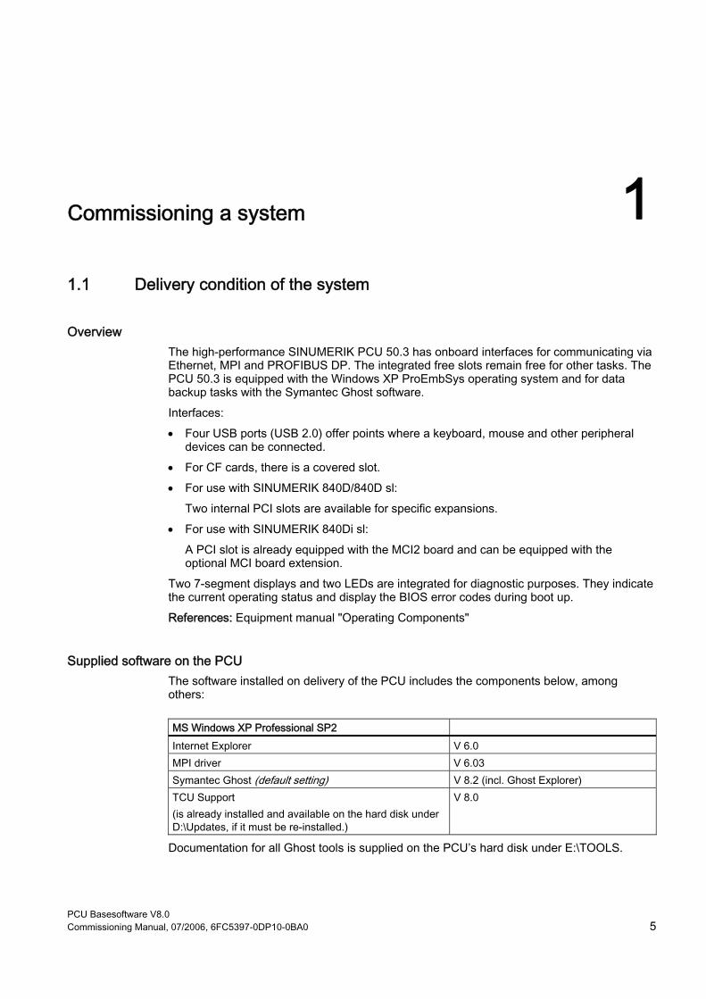
PCU Basesoftware V8.0 Commissioning Manual, 07/2006, 6FC5397-0DP10-0BA0 5
Commissioning a system 11.1 Delivery condition of the system
Overview The high-performance SINUMERIK PCU 50.3 has onboard interfaces for communicating via Ethernet, MPI and PROFIBUS DP. The integrated free slots remain free for other tasks. The PCU 50.3 is equipped with the Windows XP ProEmbSys operating system and for data backup tasks with the Symantec Ghost software. Interfaces: • Four USB ports (USB 2.0) offer points where a keyboard, mouse and other peripheral
devices can be connected. • For CF cards, there is a covered slot. • For use with SINUMERIK 840D/840D sl:
Two internal PCI slots are available for specific expansions. • For use with SINUMERIK 840Di sl:
A PCI slot is already equipped with the MCI2 board and can be equipped with the optional MCI board extension.
Two 7-segment displays and two LEDs are integrated for diagnostic purposes. They indicate the current operating status and display the BIOS error codes during boot up. References: Equipment manual "Operating Components"
Supplied software on the PCU The software installed on delivery of the PCU includes the components below, among others:
MS Windows XP Professional SP2 Internet Explorer V 6.0 MPI driver V 6.03 Symantec Ghost (default setting) V 8.2 (incl. Ghost Explorer) TCU Support (is already installed and available on the hard disk under D:\Updates, if it must be re-installed.)
V 8.0
Documentation for all Ghost tools is supplied on the PCU’s hard disk under E:\TOOLS.
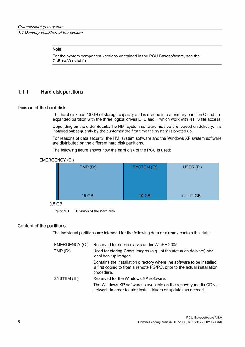
Commissioning a system 1.1 Delivery condition of the system
PCU Basesoftware V8.0 6 Commissioning Manual, 07/2006, 6FC5397-0DP10-0BA0
Note For the system component versions contained in the PCU Basesoftware, see the C:\BaseVers.txt file.
1.1.1 Hard disk partitions
Division of the hard disk The hard disk has 40 GB of storage capacity and is divided into a primary partition C and an expanded partition with the three logical drives D, E and F which work with NTFS file access. Depending on the order details, the HMI system software may be pre-loaded on delivery. It is installed subsequently by the customer the first time the system is booted up. For reasons of data security, the HMI system software and the Windows XP system software are distributed on the different hard disk partitions. The following figure shows how the hard disk of the PCU is used:
Figure 1-1 Division of the hard disk
Content of the partitions The individual partitions are intended for the following data or already contain this data:
EMERGENCY (C:) Reserved for service tasks under WinPE 2005. TMP (D:) Used for storing Ghost images (e.g., of the status on delivery) and
local backup images. Contains the installation directory where the software to be installed is first copied to from a remote PG/PC, prior to the actual installation procedure.
SYSTEM (E:) Reserved for the Windows XP software. The Windows XP software is available on the recovery media CD via network, in order to later install drivers or updates as needed.

Commissioning a system 1.1 Delivery condition of the system
PCU Basesoftware V8.0 Commissioning Manual, 07/2006, 6FC5397-0DP10-0BA0 7
USER (F:) For installing user programs. Applications such as HMI system software (incl. data storage and temporary data), STEP7, OEM applications for HMI, or customer-specific applications should only be installed here.
Notice All of the applications must be exclusively installed on USER (F:); even if these applications have a different drive set as the default drive in their installation path. The names EMERGENCY, TMP, SYSTEM, USER must not be changed; otherwise the "ServiceCenter" (see Section 4) will no longer function.
See also Installing SINUMERIK products (Page 39) Starting ServiceCenter Backup Restore (Page 47)
1.1.2 System settings
Pre-configuration of the PCU The PCU 50.3 has two Ethernet interfaces that are suitably preset with the SINUMERIK solution line for connecting to the system network.
Eth 1 is preset as a default DHCP client for connection to a company network. Eth 2 is preset as a SINUMERIK DHCP server for connection to a system network. Eth 2 is preset to the fixed IP address 192.168.214.241.
The presetting of both Ethernet interfaces should not be changed. Exception: several PCUs in the system network. References: Commissioning manual Thin client configuration
Name of the PCU Upon delivery of the system, a unique computer name is generated which can be read out under: "Start" → "Settings" → "Control Panel" → "System", Register "Computer Name".

Commissioning a system 1.1 Delivery condition of the system
PCU Basesoftware V8.0 8 Commissioning Manual, 07/2006, 6FC5397-0DP10-0BA0
Configuration of the operating system For safety reasons, Windows XP has been preset as follows: • The Autorun function is deactivated. • Automatic Windows Update is deactivated. • Monitoring and alerts for antivirus software and automatic update are deactivated. • Links used to call up Internet Explorer from the service desktop and the start menu are
removed. • Remote Procedure Call (RPC) is possible for calls that are not connected. • The firewall settings are activated on the network card Eth 1 and deactivated on Eth 2.
Changes to Windows services Other default settings:
Windows services: Start-up type: Computer Browser Manual (Not started) Error Reporting Service Disabled Portable Media Serial Number Manual (Not started) SSDP Discovery Service Disabled Universal Plug and Play Host Disabled Web Client Manual (Not started) Wireless Zero Configuration Manual (Not started)
Preset users Upon delivery of the system, the following users are defined at the factory:
User name Password User type Windows user group operator operator HMI Users Operator auduser SUNRISE Service user System administrator siemens ***** --- System administrator
Starting ServiceCenter Using this link on the service desktop, you can start the service center users. In service center users, the boot up behavior of the PCU is globally set for all users or individual users.

Commissioning a system 1.2 User administration
PCU Basesoftware V8.0 Commissioning Manual, 07/2006, 6FC5397-0DP10-0BA0 9
1.2 User administration
1.2.1 Which users are set up?
Overview The users are managed in the "ServiceCenter Users", so that the commissioner/service user no longer has to make corresponding settings directly in the registry. The preset users are: • The "auduser".
The "auduser" is a service user type of user and belongs to the system administrators' user group. The system administrators have the user rights of a local administrator.
• The "operator" The "operator" is an HMI user type of user and belongs to the operators' user group. The operators have limited user rights.
For the HMI user and service user, individual settings can be configured for boot up, the HMI program and service.
Notice In the PCU Basesoftware version 8.0 SP2, only one service user ("auduser" is the default) and only one HMI user with the fixed name of "operator" are supported.
Users Each user is from one user type and belongs to one user group.
User type A user can be assigned to the following user types:
User types Task card HMI Users • Boot up of the PCU
• Operating the HMI program Service user • Service tasks
• Boot up of the PCU • Operating the HMI program
The user types are implemented under Windows in user groups with various user rights.
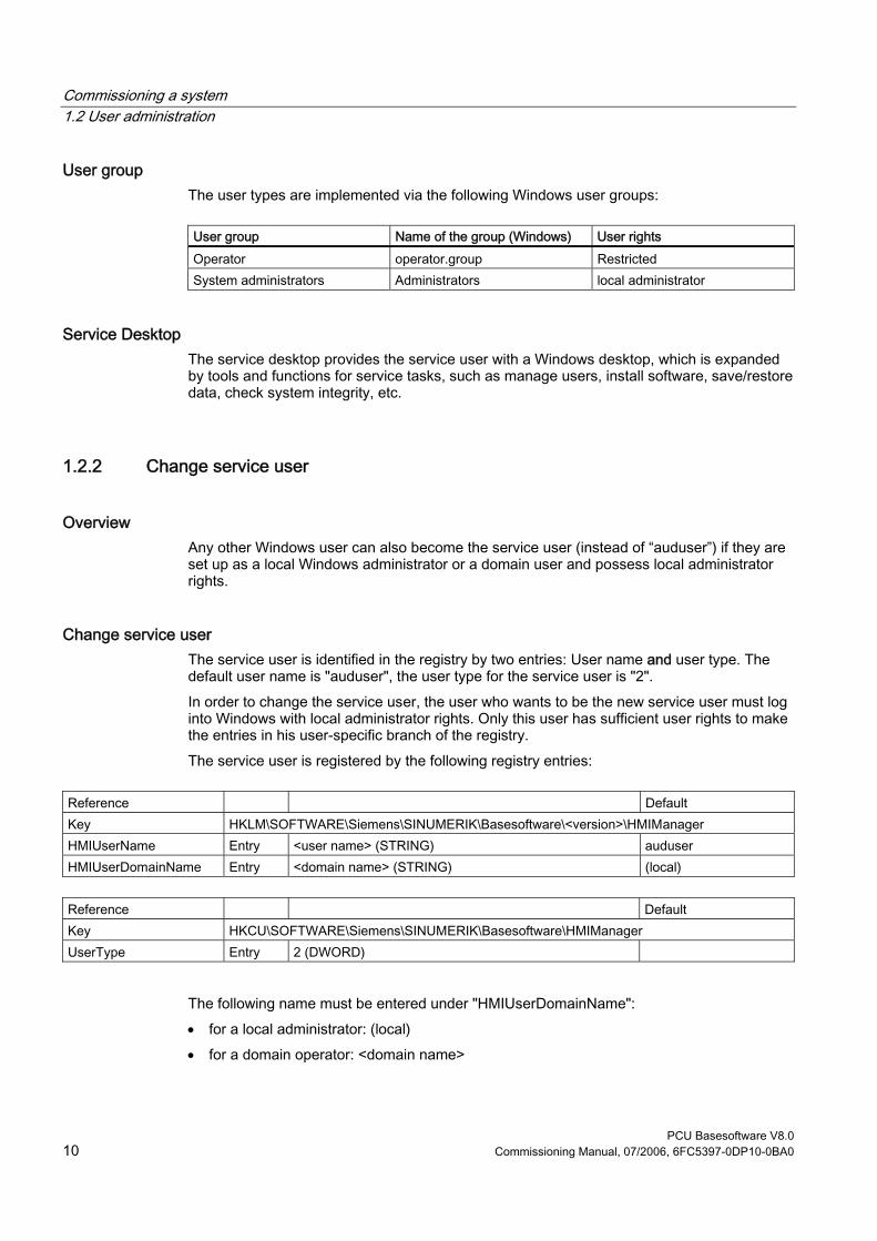
Commissioning a system 1.2 User administration
PCU Basesoftware V8.0 10 Commissioning Manual, 07/2006, 6FC5397-0DP10-0BA0
User group The user types are implemented via the following Windows user groups:
User group Name of the group (Windows) User rights Operator operator.group Restricted System administrators Administrators local administrator
Service Desktop The service desktop provides the service user with a Windows desktop, which is expanded by tools and functions for service tasks, such as manage users, install software, save/restore data, check system integrity, etc.
1.2.2 Change service user
Overview Any other Windows user can also become the service user (instead of “auduser”) if they are set up as a local Windows administrator or a domain user and possess local administrator rights.
Change service user The service user is identified in the registry by two entries: User name and user type. The default user name is "auduser", the user type for the service user is "2". In order to change the service user, the user who wants to be the new service user must log into Windows with local administrator rights. Only this user has sufficient user rights to make the entries in his user-specific branch of the registry. The service user is registered by the following registry entries:
Reference Default Key HKLM\SOFTWARE\Siemens\SINUMERIK\Basesoftware\<version>\HMIManager HMIUserName Entry <user name> (STRING) auduser HMIUserDomainName Entry <domain name> (STRING) (local)
Reference Default Key HKCU\SOFTWARE\Siemens\SINUMERIK\Basesoftware\HMIManager UserType Entry 2 (DWORD)
The following name must be entered under "HMIUserDomainName": • for a local administrator: (local) • for a domain operator: <domain name>
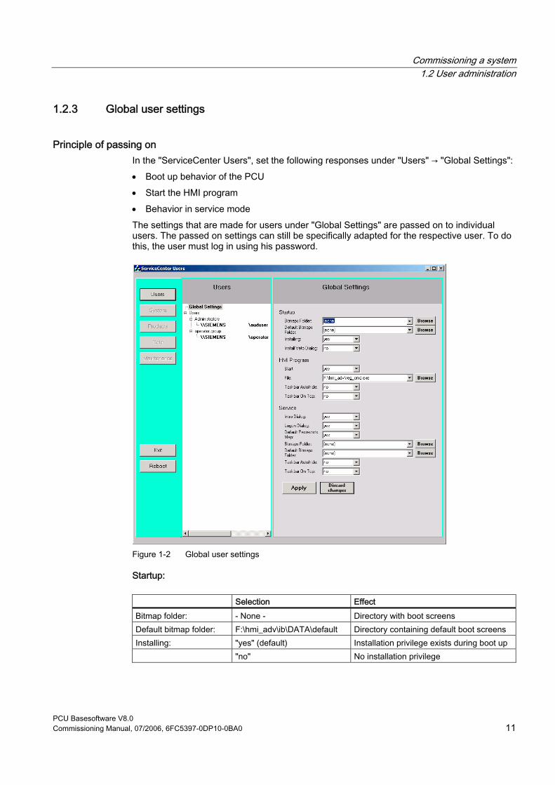
Commissioning a system 1.2 User administration
PCU Basesoftware V8.0 Commissioning Manual, 07/2006, 6FC5397-0DP10-0BA0 11
1.2.3 Global user settings
Principle of passing on In the "ServiceCenter Users", set the following responses under "Users" → "Global Settings": • Boot up behavior of the PCU • Start the HMI program • Behavior in service mode The settings that are made for users under "Global Settings" are passed on to individual users. The passed on settings can still be specifically adapted for the respective user. To do this, the user must log in using his password.
Figure 1-2 Global user settings
Startup:
Selection Effect Bitmap folder: - None - Directory with boot screens Default bitmap folder: F:\hmi_adv\ib\DATA\default Directory containing default boot screens Installing: "yes" (default) Installation privilege exists during boot up "no" No installation privilege

Commissioning a system 1.2 User administration
PCU Basesoftware V8.0 12 Commissioning Manual, 07/2006, 6FC5397-0DP10-0BA0
Selection Effect Install veto dialog: "no" (default) For pending installation during the boot
up: No prompting, the installation begins immediately.
"yes" For pending installation during the boot up: Prompt asking whether to install.
HMI program:
Selection Effect Start: "yes" (default) The HMI program is started. "no" The HMI program is not started. File: F:\hmi_adv\reg_cmd.exe
(default) Directory of the HMI program
Task bar autohide: "no" (default) HMI program: Hide start task bar "yes" HMI program: Show start task bar Task bar on top: "no" (default) HMI program: Start task bar in the
background "yes" HMI program: Start task bar on top
Service:
Selection Effect Intro dialog: "yes" (default) Display service intro dialog "no" Do not display service intro dialog Logon dialog: "yes" (default) Display service logon dialog "no" Do not display service logon dialog Default password map: "yes" (default) The password is not case-sensitive. "no" The password must be entered exactly as
specified. Bitmaps folder: - None - Directory with background screens for the
service desktop Default bitmap folder: - None - Directory with default background screens for
the service desktop Task bar autohide: "no" (default) Service Desktop: Hide start task bar "yes" Service Desktop: Show start task bar Task bar on top: "no" (default) Service Desktop: Start task bar on top "yes" Service Desktop: Start task bar in the
background
Note If you press the "Reboot" button, the system immediately reboots (without prior prompting). Use "Exit" to end the ServiceCenter Users.

Commissioning a system 1.2 User administration
PCU Basesoftware V8.0 Commissioning Manual, 07/2006, 6FC5397-0DP10-0BA0 13
Service dialogs during boot up The following dialogs are shown during boot up: • The Service Intro Dialog is shown, if no HMI program is installed or the start of the HMI
program is deactivated.
Figure 1-3 Service Intro Dialog
• If a service user wants to log in, the Service Logon Dialog is displayed: – After pressing key <3> during boot up. – After pressing the "Service" button in the service intro dialog.
Figure 1-4 Service Logon Dialog

Commissioning a system 1.2 User administration
PCU Basesoftware V8.0 14 Commissioning Manual, 07/2006, 6FC5397-0DP10-0BA0
1.2.4 Specific user settings
Passing on settings The settings that are made for users under "Global Settings" are passed on to the respective user.
Example: "operator" After the password is entered, the settings can be user-specifically adapted. The settings that cannot be changed are displayed with a grey background.
Figure 1-5 User settings for the "operator"

Commissioning a system 1.3 Boot up behavior of the PCU
PCU Basesoftware V8.0 Commissioning Manual, 07/2006, 6FC5397-0DP10-0BA0 15
1.3 Boot up behavior of the PCU
1.3.1 Boot up of the PCU: no HMI program installed
Requirement No HMI program is installed during the PCU boot up.
Ramp-up phase
Figure 1-6 PCU bootup diagram (without HMI program)
Explanations: • If installation programs (such as HMI Advanced) are present in directory D:\Install, you
will be prompted during the first boot up as to whether the installation procedure should be started. After installation is completed, you need to restart the system. The installation can also be skipped and carried out later.
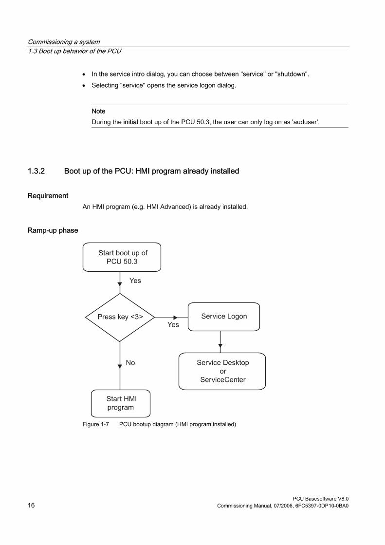
Commissioning a system 1.3 Boot up behavior of the PCU
PCU Basesoftware V8.0 16 Commissioning Manual, 07/2006, 6FC5397-0DP10-0BA0
• In the service intro dialog, you can choose between "service" or "shutdown". • Selecting "service" opens the service logon dialog.
Note During the initial boot up of the PCU 50.3, the user can only log on as 'auduser'.
1.3.2 Boot up of the PCU: HMI program already installed
Requirement An HMI program (e.g. HMI Advanced) is already installed.
Ramp-up phase
Figure 1-7 PCU bootup diagram (HMI program installed)
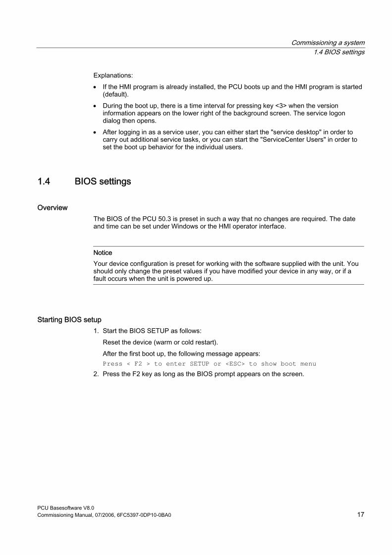
Commissioning a system 1.4 BIOS settings
PCU Basesoftware V8.0 Commissioning Manual, 07/2006, 6FC5397-0DP10-0BA0 17
Explanations: • If the HMI program is already installed, the PCU boots up and the HMI program is started
(default). • During the boot up, there is a time interval for pressing key <3> when the version
information appears on the lower right of the background screen. The service logon dialog then opens.
• After logging in as a service user, you can either start the "service desktop" in order to carry out additional service tasks, or you can start the "ServiceCenter Users" in order to set the boot up behavior for the individual users.
1.4 BIOS settings
Overview The BIOS of the PCU 50.3 is preset in such a way that no changes are required. The date and time can be set under Windows or the HMI operator interface.
Notice Your device configuration is preset for working with the software supplied with the unit. You should only change the preset values if you have modified your device in any way, or if a fault occurs when the unit is powered up.
Starting BIOS setup 1. Start the BIOS SETUP as follows:
Reset the device (warm or cold restart). After the first boot up, the following message appears: Press < F2 > to enter SETUP or <ESC> to show boot menu
2. Press the F2 key as long as the BIOS prompt appears on the screen.
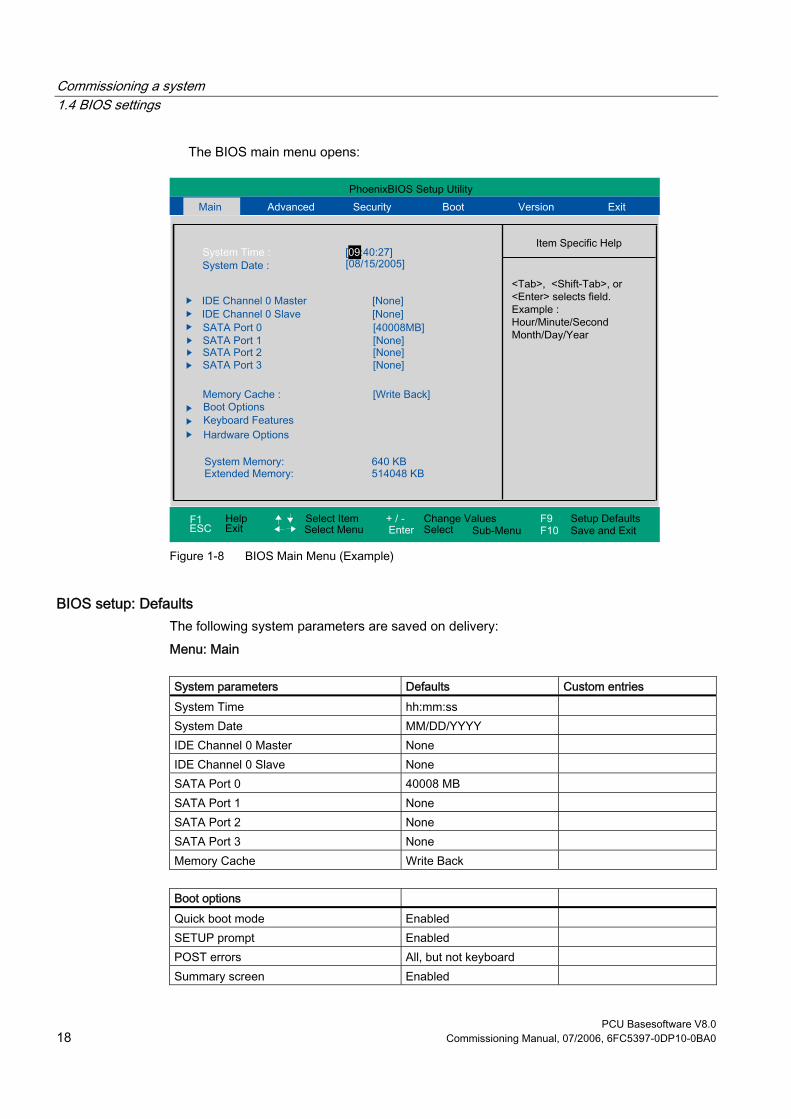
Commissioning a system 1.4 BIOS settings
PCU Basesoftware V8.0 18 Commissioning Manual, 07/2006, 6FC5397-0DP10-0BA0
The BIOS main menu opens:
Figure 1-8 BIOS Main Menu (Example)
BIOS setup: Defaults The following system parameters are saved on delivery: Menu: Main
System parameters Defaults Custom entries System Time hh:mm:ss System Date MM/DD/YYYY IDE Channel 0 Master None IDE Channel 0 Slave None SATA Port 0 40008 MB SATA Port 1 None SATA Port 2 None SATA Port 3 None Memory Cache Write Back
Boot options Quick boot mode Enabled SETUP prompt Enabled POST errors All, but not keyboard Summary screen Enabled

Commissioning a system 1.4 BIOS settings
PCU Basesoftware V8.0 Commissioning Manual, 07/2006, 6FC5397-0DP10-0BA0 19
Boot options Diagnostic screen Enabled Post Code/Status LPC Bus
Keyboard features Numlock ON Key click Disabled Keyboard auto-repeat rate 30 / sec Keyboard auto-repeat delay ½ sec
Hardware Options PCI MPI/DP Enabled Onboard Ethernet 1 Enabled On-board Ethernet 1 Address 08 00 06 90 xx xx On-board Ethernet 1 Remote Boot Enabled Onboard Ethernet 2 Enabled On-board Ethernet 2 Address 08 00 06 90 xx xx On-board Ethernet 2 Remote Boot Disabled SafeCard functions Enabled Fan control Enabled CRT/LCD selection Simultan. Auto
Menu: Advanced
System parameters Defaults Custom entries Installed O/S Other Reset configuration data No Legacy USB support Disabled USB controller restart Enabled I/O Device Configuration Internal COM 1 Enabled Base I/O address 3F8 Interrupt IRQ 4
PCI Configuration PCI device slot 1 Option ROM scan Enabled Enable master Enabled Latency timer Default PCI device slot 2 Option ROM scan Enabled Enable master Enabled Latency timer Default
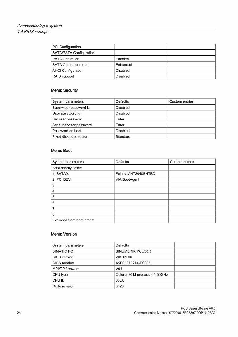
Commissioning a system 1.4 BIOS settings
PCU Basesoftware V8.0 20 Commissioning Manual, 07/2006, 6FC5397-0DP10-0BA0
PCI Configuration SATA/PATA Configuration PATA Controller: Enabled SATA Controller mode Enhanced AHCI Configuration Disabled RAID support Disabled
Menu: Security
System parameters Defaults Custom entries Supervisor password is Disabled User password is Disabled Set user password Enter Set supervisor password Enter Password on boot Disabled Fixed disk boot sector Standard
Menu: Boot
System parameters Defaults Custom entries Boot priority order: 1: SATA0: Fujitsu MHT2040BHTBD 2: PCI BEV: VIA BootAgent 3: 4: 5: 6: 7: 8: Excluded from boot order:
Menu: Version
System parameters Defaults SIMATIC PC SINUMERIK PCU50.3 BIOS version V05.01.06 BIOS number A5E00370214-ES005 MPI/DP firmware V01 CPU type Celeron ® M processor 1.50GHz CPU ID 06D8 Code revision 0020
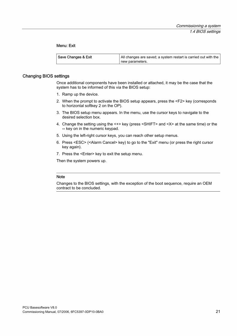
Commissioning a system 1.4 BIOS settings
PCU Basesoftware V8.0 Commissioning Manual, 07/2006, 6FC5397-0DP10-0BA0 21
Menu: Exit
Save Changes & Exit All changes are saved; a system restart is carried out with the new parameters.
Changing BIOS settings Once additional components have been installed or attached, it may be the case that the system has to be informed of this via the BIOS setup: 1. Ramp up the device. 2. When the prompt to activate the BIOS setup appears, press the <F2> key (corresponds
to horizontal softkey 2 on the OP). 3. The BIOS setup menu appears. In the menu, use the cursor keys to navigate to the
desired selection box. 4. Change the setting using the <+> key (press <SHIFT> and <X> at the same time) or the
↔ key on in the numeric keypad. 5. Using the left-right cursor keys, you can reach other setup menus. 6. Press <ESC> (<Alarm Cancel> key) to go to the "Exit" menu (or press the right cursor
key again). 7. Press the <Enter> key to exit the setup menu. Then the system powers up.
Note Changes to the BIOS settings, with the exception of the boot sequence, require an OEM contract to be concluded.


PCU Basesoftware V8.0 Commissioning Manual, 07/2006, 6FC5397-0DP10-0BA0 23
Configuring the system 22.1 System features
Changing the name of the PCU You can change the name of the PCU under: "Start" → "Control Panel" → "System" on the "Computer Name" tab and by pressing the "Change" button.
Figure 2-1 Changing the name of the PCU
Setting the IP addresses to Eth1 and Eth2 of the PCU 50.3 References: Commissioning manual Thin client configuration
See also System settings (Page 7)
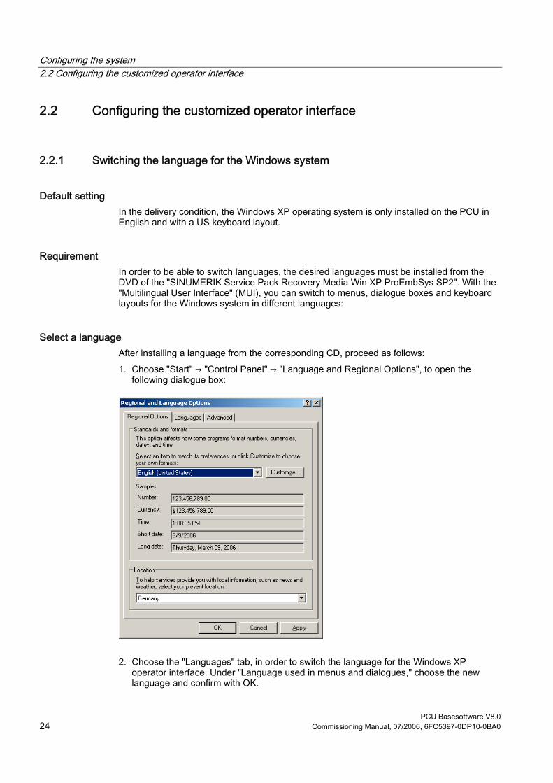
Configuring the system 2.2 Configuring the customized operator interface
PCU Basesoftware V8.0 24 Commissioning Manual, 07/2006, 6FC5397-0DP10-0BA0
2.2 Configuring the customized operator interface
2.2.1 Switching the language for the Windows system
Default setting In the delivery condition, the Windows XP operating system is only installed on the PCU in English and with a US keyboard layout.
Requirement In order to be able to switch languages, the desired languages must be installed from the DVD of the "SINUMERIK Service Pack Recovery Media Win XP ProEmbSys SP2". With the "Multilingual User Interface" (MUI), you can switch to menus, dialogue boxes and keyboard layouts for the Windows system in different languages:
Select a language After installing a language from the corresponding CD, proceed as follows: 1. Choose "Start" → "Control Panel" → "Language and Regional Options", to open the
following dialogue box:
2. Choose the "Languages" tab, in order to switch the language for the Windows XP operator interface. Under "Language used in menus and dialogues," choose the new language and confirm with OK.

Configuring the system 2.2 Configuring the customized operator interface
PCU Basesoftware V8.0 Commissioning Manual, 07/2006, 6FC5397-0DP10-0BA0 25
3. On the "Advanced" tab, choose the language for programs that do not support Unicode.
Result To make the language change effective, the PCU must be rebooted. The selectable languages are displayed using the font set of the respective language.
Notice The settings for the keyboard layout and the formats for date, time and number displays on the "Regional Options" tab must not be changed . These settings are automatically adjusted depending on the language selected for the operator interface under HMI Advanced.
See also Installing additional languages under Windows XP (DVD) (Page 43)
Configuring the system 2.2 Configuring the customized operator interface
PCU Basesoftware V8.0 26 Commissioning Manual, 07/2006, 6FC5397-0DP10-0BA0
2.2.2 Storage location of HMI boot screen
Default setting The Siemens boot screens are stored under the path below on the appropriate PCU, e.g., for the SINUMERIK 840D sl controller: F:\hmi_adv\ib\DATA\10700\0\<Resolution>\10700_0.bmp A directory tree can also be created for manufacturer-specific boot screens. The manufacturer’s screens can then be saved in accordance with the schematic below: Directory tree of manufacturer-specific boot screens: F:\oem\ib\DATA\<NckType>\<Resolution>\<Name>.bmp
<NckType> stands for:
0 840D 2000 810D
10700 840D sl 15000 840Di sl
<Resolution>: 640 or 800 or 1024 dpi If you want the same screen to be used each time (NCU-independent screen), it can be saved in the "default" directory in the required resolutions. If you want to be able to use different screens for different NCUs, they should be saved in the <NckType>\<Resolution> subdirectories using the appropriate resolution.
Screen name and resolution <Name>.bmp: The name can be selected freely; only one file is permitted per directory. The screens must be created with a graphics tool in the resolution indicated by the subdirectory name and stored in the corresponding directory. The HMI software selects the screen, depending on the NCK type and the resolution of the available operator panel.
2.2.3 Displaying your own boot screen
Requirements Set up a directory containing several boot screens (for different panel resolutions). This directory should be segmented into subdirectories 640, 800 and 1024, which each contain a boot screen of the appropriate resolution. A directory containing boot screens can also be set up, likewise divided into subdirectories 640, 800 and 1024. The boot screen stored there for a particular resolution is displayed if no boot screen (including one with a lower resolution) is found in the booting-screen directory described above. If no boot screen (including one with a lower resolution) is found, a general boot screen is displayed, which is part of the PCU basic software.
Configuring the system 2.2 Configuring the customized operator interface
PCU Basesoftware V8.0 Commissioning Manual, 07/2006, 6FC5397-0DP10-0BA0 27
Directories The directories can be user-specifically set in ServiceCenter Users under: • Startup: Bitmaps folder • Startup: Default bitmap folder
2.2.4 Changing the background of the service desktop
Overview A background pattern for the service desktop is not set via the "Control Panel" (system control), but in the registry: • Background pattern:
Key: HKLM\SOFTWARE\Siemens\SINUMERIK\Basic software\
<version>\HMI desktop Value: Pattern (STRING) Date: <bit code>” (e.g., “0 80 114 32 0 5 39 2”, see HKCU\Control Panel\Patterns)
“(None)” (= NO background pattern) Init data: Background pattern previously set via the Control Panel Default data: “(None)” (if entry is not available/readable)
• Background image:
A background screen for the service desktop is not user-specifically set via the "Control Panel" (system control), but in the ServiceCenter Users under "Service: Bitmap Folders" or "Service: Default Bitmap Folders".
Note An attempt to set the service desktop background (as in standard Windows) via the Control Panel does not affect the service desktop background display, but only the boot screen display.

Configuring the system 2.3 User -specific settings during boot up
PCU Basesoftware V8.0 28 Commissioning Manual, 07/2006, 6FC5397-0DP10-0BA0
2.3 User-specific settings during boot up
Overview If an HMI program, e.g., HMI Advanced, is to be started following booting, the settings and functionality differ from those that apply if the service desktop is to be started.
2.3.1 Starting an HMI program during boot up
Filtering keys During boot up of an HMI program, keystroke sequences and pressed function keys are simultaneously filtered. The keystroke sequences and functions that were pressed simultaneously and are to be filtered can be configured in file E:\Windows\System.ini. Filtering keystroke sequences:
Section: MMC103Keyb Key: SeqAct Value: <bit mask>
(= keystroke sequences to be filtered, specified in accordance with the comment in E:\Windows\System.ini)
Init value: 262143
Filtering function keys that were pressed simultaneously:
Section: MMC103Keyb Key: ConcurrentKeyMask Value: <bit mask>
(= function keys to be filtered, specified in accordance with the comment in E:\Windows\System.ini)
Init value: 255

Configuring the system 2.3 User -specific settings during boot up
PCU Basesoftware V8.0 Commissioning Manual, 07/2006, 6FC5397-0DP10-0BA0 29
Starting additional programs Programs can also be started at the same time as the HMI program and are started automatically by Windows when the service desktop is opened. This start in parallel to the HMI program can be configured. If the programs to be started are located in the Windows directories of E:\Documents and Settings, the following registry entry must be set:
Key: HKLM\SOFTWARE\Siemens\SINUMERIK\Basic software\ <version>\HMI
Manager Value: StartSINHMIStartupDirsPrograms (DWORD) Date: 1 (the programs are started) or
0 (the programs are NOT started) Init data: 0 Default data: 0 (if entry is not available/readable)
If the programs to be started are set in the registry entries 'HKCU\Software\Microsoft\Windows\CurrentVersion\Run' and 'HKLM\Software\Microsoft\Windows\CurrentVersion\Run', the following registry entry must be set:
Key: HKLM\SOFTWARE\Siemens\SINUMERIK\Basic software\ <version>\HMI
Manager Value: StartSINHMIRunPrograms (DWORD) Date: 1 (the programs are started) or
0 (the programs are NOT started) Init data: 0 Default data: 0 (if entry is not available/readable)
Executing an HMI program While the HMI program is being executed, Windows Explorer runs in the background and its settings (disabled browser functionality, taskbar, start menu, ...) prevent the Windows platform being accessed unintentionally. The behavior of the taskbar can be user-specifically set in the ServiceCenter Users under "HMI program" using "Taskbar Autohide" and "Taskbar On Top".
Ending an HMI program When the HMI program is ended, Windows XP shuts down completely.

Configuring the system 2.3 User -specific settings during boot up
PCU Basesoftware V8.0 30 Commissioning Manual, 07/2006, 6FC5397-0DP10-0BA0
2.3.2 Starting service des ktop during boot up
Filtering keys The keystroke sequences and function keys that are pressed simultaneously are filtered as a function of the configuration in file: E:\Windows\System.ini Filtering keystroke sequences:
Section: MMC103Keyb Key: KeySequencesEnable Value: 1 (= filtering of keystroke sequences specified in the SeqAct key) or
0 (= NO filtering) Init value: 0 Default value: 0 (if entry is not available/readable):
Key: SeqAct Value: <bit mask> (= keystroke sequences to be filtered, specified in accordance
with the comment in E:\Windows\System.ini) Init value: 262143
Filtering function keys that were pressed simultaneously:
Section: MMC103Keyb Key: ConcurrentKeyEnable Value: 1 (= filtering of function keys specified in the ConcurrentKeyMask key) or
0 (= NO filtering) Init value: 1 Default value: 0 (if entry is not available/readable)
Key: ConcurrentKeyMask Value: <bit mask> (= function keys to be filtered, specified in accordance with the
comment in E:\Windows\System.ini) Init value: 255
Starting the service desktop The Windows platform is freely accessible via the service desktop. When the service desktop is started, all of the programs that would automatically be started by Windows (standard version) during log-in are also started.
Executing an HMI program The HMI program can also be started from the service desktop.

Configuring the system 2.3 User -specific settings during boot up
PCU Basesoftware V8.0 Commissioning Manual, 07/2006, 6FC5397-0DP10-0BA0 31
Ending an HMI program When an HMI program started from the service desktop is exited, you are returned to the service desktop.
Saving the service desktop (default) The settings on the service desktop (e.g. arrangement of the links on the service desktop) are not saved when you log off. A service technician should always find the same starting condition on the service desktop, not the settings from a previous session.
Saving the settings of the service Desktop This behavior can be changed by making an entry in the registry. The following settings can be saved via this registry entry: • Positions of open windows • Size and position of the task bar • Moving and deleting links Key: HKLM\SOFTWARE\Siemens\SINUMERIK\Basic software\ <version>\HMI
Manager Value: SaveSINDesktopSettings (DWORD) Date: 1 (the settings are saved) or
0 (the settings are NOT saved) Init data: - Value is not created by the basic software - Default data: 0 (if entry is not available/readable)
The key is effective for all service users and other users. Links on the service desktop are always saved, irrespective of the registry entry.
Note Application windows that are still open before logging out, must be closed by the setting "Save settings" before exiting the service desktop. Otherwise, these application windows will briefly be displayed and then closed again during a restart immediately before the HMI program starts.

Configuring the system 2.4 PCU 50.3 with SITOP UPS module
PCU Basesoftware V8.0 32 Commissioning Manual, 07/2006, 6FC5397-0DP10-0BA0
2.3.3 Starting OEM programs
Overview You can start OEM programs directly before starting the HMI system software. This requires these programs (or their links) to be stored in subdirectories of the directory C:\RunOEM.
Starting sequence The subdirectories are executed in the order listed. The programs within a subdirectory are started in the chronological order in which they were placed in the subdirectory. • Programs in the C:\RunOEM\SeqOnce subdirectory are started once and sequentially,
i.e., a program is not started until the previously started program is completed. • Programs in the C:\RunOEM\Seq subdirectory are started sequentially whenever the
system is ramped up, i.e., a program is not started until the previously started program is completed.
• Programs in the C:\RunOEM\ParOnce subdirectory are started once and simultaneously. They run parallel with the HMI system software.
• Programs in the C:\RunOEM\Par subdirectory are started simultaneously whenever the system is ramped up. They run parallel with the HMI system software.
Not only program files, but also other types of file can be stored in the subdirectories, which are then opened in accordance with their file type. For example, ".txt" files are opened using Notepad, ".htm" files are opened using Internet Explorer.
2.4 PCU 50.3 with SITOP UPS module
Application (Version 2.6.0.1) If the supply voltage at the PCU dips, the SITOP UPS modules below could maintain operation for a limited period if a backup battery is being used, allowing the PCU to be properly shut down before the battery is exhausted:
Identifier Order number (MLFB) SITOP POWER DC UPS module 15 (USB interface) 6EP1931-2EC41
Requirements • PCU basic software WinXP V08.00.00 of higher for USB port • HMI Advanced 07.01.00 or higher • SITOP software, V2.5.2.4 or higher is installed:
SITOP software is available for download from: http://www.ad.siemens.de/sitop

Configuring the system 2.4 PCU 50.3 with SITOP UPS module
PCU Basesoftware V8.0 Commissioning Manual, 07/2006, 6FC5397-0DP10-0BA0 33
• SITOP monitor/configuration program is installed: To enable this, the SITOP software must be copied to the E:\SITOP directory set up on the PCU. This directory already contains PCU tools required for shutdown on the SITOP UPS. If this directory does not exist in an older version of the PCU basic software, it must be created so that it will be compatible for any subsequent updating of the PCU basic software.
• UPS USB driver for Windows XP is installed: Installation is described in the relevant SITOP documentation. The documentation is part of the SITOP software download package.
• The SITOP UPS hardware is connected.
Test environment The "SITOP UPS" function has been tested in the standard configuration of HMI Advanced. When installing add-on or OEM software components, the shutdown procedure of the complete system has to be checked by the operator.
2.4.1 Starting and configuring the SITOP monitor
Windows boot up The SITOP monitor has to be started by Windows automatically during booting. A new value has to be entered for the SITOP monitor under the key below in the Windows registry:
HKEY_LOCAL_MACHINE\SOFTWARE\Microsoft\Windows\CurrentVersion\Run ValueName: SITOP
ValueType: REG_SZ Value Data: E:\SITOP\SITOP_DC_USV.exe
A script file, sitop.reg, is located in the E:\SITOP directory. The required key is entered into the registry automatically if this file is executed. The SITOP monitor is started automatically once the PCU is restarted. The next installation step is to configure the monitor.
Notice The SITOP monitor must not be started via the Windows Autostart directory.
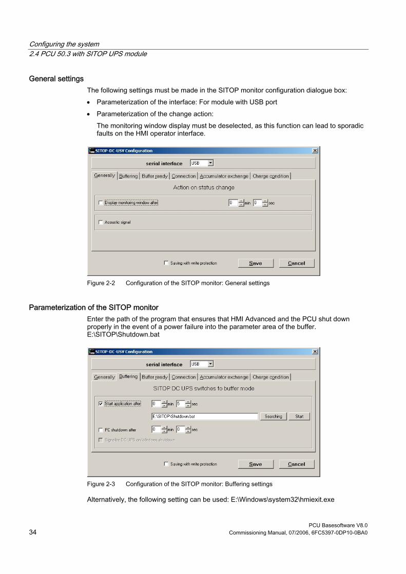
Configuring the system 2.4 PCU 50.3 with SITOP UPS module
PCU Basesoftware V8.0 34 Commissioning Manual, 07/2006, 6FC5397-0DP10-0BA0
General settings The following settings must be made in the SITOP monitor configuration dialogue box: • Parameterization of the interface: For module with USB port • Parameterization of the change action:
The monitoring window display must be deselected, as this function can lead to sporadic faults on the HMI operator interface.
Figure 2-2 Configuration of the SITOP monitor: General settings
Parameterization of the SITOP monitor Enter the path of the program that ensures that HMI Advanced and the PCU shut down properly in the event of a power failure into the parameter area of the buffer. E:\SITOP\Shutdown.bat
Figure 2-3 Configuration of the SITOP monitor: Buffering settings
Alternatively, the following setting can be used: E:\Windows\system32\hmiexit.exe

Configuring the system 2.4 PCU 50.3 with SITOP UPS module
PCU Basesoftware V8.0 Commissioning Manual, 07/2006, 6FC5397-0DP10-0BA0 35
2.4.2 Configuration of the SITOP UPS module
Buffering parameterization The UPS module can be used to select whether buffering should be completed after a predetermined period of time or not until the accumulator’s lowest discharge threshold (= maximum buffer time) has been reached. Both buffering parameterizations result from this.
"Maximum buffer time" mode (PCU basic software XP 08.00.00 or higher) This mode enables the system to be shut down in a time-optimized manner. The UPS module is synchronized with the shutdown of the operating system. Buffering is maintained until the operating system has been shut down. The operating system must shut down within a maximum of five minutes (including all applications). Otherwise, the UPS module buffers for the maximum buffer time (dependent on the accumulator state). Required settings on the UPS module (USB interface)
On - Off
1 +2V 2 +1V 3 +0.5V
Cut-in threshold +22V (fixed)
4 +1V 5 +1V 6 +0.5V 7 +0.2V 8 +0.2V 9 +0.1V
End-of-charge voltage + 26.3V fixed
10 0.35A / 0.7A Charging current
On - Off 1 Set time/max. time 2 +320 s 3 +160 s 4 +80s 5 +40 s 6 +20 s 7 +10 s
Buffer time +5 s fixed
8 Disconnection 9 Accumulator operating state on/off
Legend: Delivery condition setting
Setting for operation on the PCU 50

Configuring the system 2.4 PCU 50.3 with SITOP UPS module
PCU Basesoftware V8.0 36 Commissioning Manual, 07/2006, 6FC5397-0DP10-0BA0
“Fixed buffer time” mode In this mode, the UPS module always buffers for the pre-selected, fixed period of time. It is not possible to synchronize the UPS module with the operating system shutdown. Required settings on the UPS module
On - Off
1 +2V 2 +1V 3 +0.5V
Cut-in threshold +22V (fixed)
4 +1V 5 +1V 6 +0.5V 7 +0.2V 8 +0.2V 9 +0.1V
∘ ∘ End-of-charge voltage + 26.3V fixed
10 0.35A / 0.7A Charging current
On - Off 1 Set time/max. time 2 +320 s 3 +160 s 4 +80s 5 +40 s 6 +20 s 7 +10 s
∘ ∘ Buffer time +5 s fixed
8 Disconnection 9 Accumulator operating state on/off
Legend: Delivery condition setting
Setting for operation on the PCU 50
Configuring the system 2.4 PCU 50.3 with SITOP UPS module
PCU Basesoftware V8.0 Commissioning Manual, 07/2006, 6FC5397-0DP10-0BA0 37
2.4.3 Configuration for exiting the HMI
HMI monitoring Exiting of the HMI advanced is monitored by a separate application, hmiexit.exe. This application is started implicitly via the shutdown.bat batch file. In case of error, the application forces the operating system to shut down. An error occurs if the HMI cannot be exited within the configured delay. Optionally, the parameters below can be set for hmiexit in file: E:\SITOP\hmiexit.ini. [Actions] #Waiting time in seconds for closing HMI Advanced applications Wait = 120 # Action on expiration of the waiting time ForceShutdown = True These default settings only need to be changed if it takes longer than 120 seconds to exit the HMI applications in an OEM installation. This configuration is not usually changed.
Configuring the EXIT button During production, the option to shut down the HMI via the EXIT button in the operating area menu should be disabled, as this function cannot be synchronized with the UPS module. The EXIT button is disabled by entering ExitButton=False in the Regie.ini file.
Hibernate The operating system’s hibernate mode is suspended when operating the UPS, as the USB interface always has to be active for the UPS module.
Note More information can be found in the product descriptions with the corresponding order number.

PCU Basesoftware V8.0 Commissioning Manual, 07/2006, 6FC5397-0DP10-0BA0 39
Install software and updates 33.1 Installing SINUMERIK products
Overview This chapter describes how to install additional software on the basis of the pre-installed PCE basic software or how to carry out an update. The description below is based on the delivery condition of the hardware and software components. The service desktop is used for the following tasks: • Installing HMI system software • Setting the running environment of the HMI system software • Checking the hard disk or version • Privilege for SIMATIC STEP 7
3.2 Installation via service desktop
Installing additional software The service desktop makes it possible to install system software or a software update. This mostly affects installation/update packages that are to be installed via the Windows network. Installation can be performed in two ways: • The installation/update package is stored in directory D:\INSTALL. When booting the
PCU the next time, the installation/update process is automatically started while booting. Only when the installation or update process is completed does normal boot manager continue and, if necessary, HMI software started.
• The installation/update process can be started from the service desktop directly by executing the installation/update package.
Using installation directories Several installation directories can be set to enable an operator setup to be executed automatically. Installation directories include the subdirectory D:\Install and the directories listed in the [SetupDirs] section of the E:\Windows\System32\HMIServe.ini parameters file. The "D:\Install" installation directory is preset there.
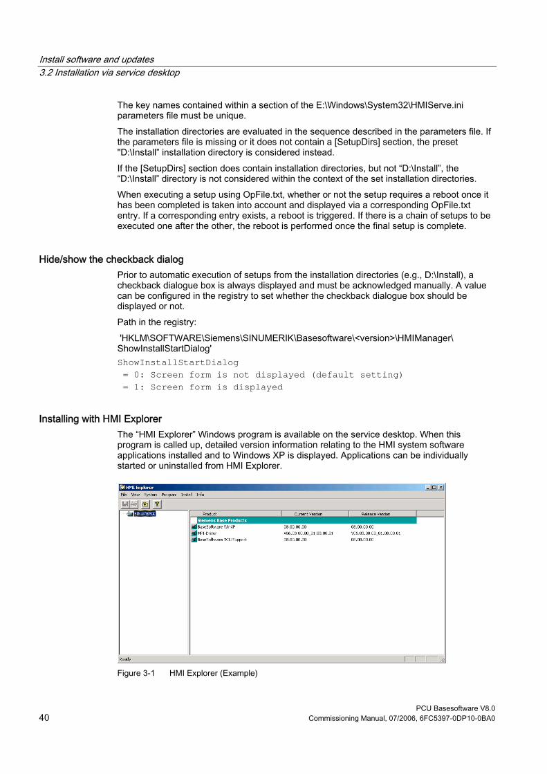
Install software and updates 3.2 Installation via service desktop
PCU Basesoftware V8.0 40 Commissioning Manual, 07/2006, 6FC5397-0DP10-0BA0
The key names contained within a section of the E:\Windows\System32\HMIServe.ini parameters file must be unique. The installation directories are evaluated in the sequence described in the parameters file. If the parameters file is missing or it does not contain a [SetupDirs] section, the preset "D:\Install” installation directory is considered instead. If the [SetupDirs] section does contain installation directories, but not “D:\Install”, the “D:\Install” directory is not considered within the context of the set installation directories. When executing a setup using OpFile.txt, whether or not the setup requires a reboot once it has been completed is taken into account and displayed via a corresponding OpFile.txt entry. If a corresponding entry exists, a reboot is triggered. If there is a chain of setups to be executed one after the other, the reboot is performed once the final setup is complete.
Hide/show the checkback dialog Prior to automatic execution of setups from the installation directories (e.g., D:\Install), a checkback dialogue box is always displayed and must be acknowledged manually. A value can be configured in the registry to set whether the checkback dialogue box should be displayed or not. Path in the registry: 'HKLM\SOFTWARE\Siemens\SINUMERIK\Basesoftware\<version>\HMIManager\ ShowInstallStartDialog' ShowInstallStartDialog = 0: Screen form is not displayed (default setting) = 1: Screen form is displayed
Installing with HMI Explorer The “HMI Explorer” Windows program is available on the service desktop. When this program is called up, detailed version information relating to the HMI system software applications installed and to Windows XP is displayed. Applications can be individually started or uninstalled from HMI Explorer.
Figure 3-1 HMI Explorer (Example)
Install software and updates 3.2 Installation via service desktop
PCU Basesoftware V8.0 Commissioning Manual, 07/2006, 6FC5397-0DP10-0BA0 41
Description of HMI Explorer The properties dialogue box gives detailed information on installing the software product: • Information on the SINUMERIK product:
The "Info" dialogue box provides information on the selected SINUMERIK product:
Current version: Specifies which version of the SINUMERIK product is currently installed. The version is shown in long form.
Internal version: Shows the current internal version number of this product. Installation Date/Time: Shows the installation date and time of the current version. Installation path: Displays the path for the main directory of the SINUMERIK
product. Start application: Gives information on the path to the *.exe file, which launches
the SINUMERIK product. • Language of the product
The "Language" dialogue box lists the installed languages for the respective SINUMERIK product and provides information on the name of the installed language. If the language is not known, an abbreviation of its name is displayed. Known languages of HMI Explorer are German, English, Spanish, French and Italian. The version of the installed language is also displayed. Information is also given regarding the installation time and date.
• History of the product The "History" dialogue box shows information on the history of the SINUMERIK product. This dialogue box gives information on the release version, any service packs and hot fixes. The "release" entry is always available. The entries for "service pack" and "hot fix" only appear if they have been installed. Information on the "version", "internal version" and "installation date/time" is given for each entry on this list.
• Component information The "Components" dialogue box shows the information on the components accompanying a product:
Component: Component name Version: Internal version of the components Path: Path of the components File: *.exe file Enable : Shows whether or not the component is enabled Description: Description of components Type: Type of components

Install software and updates 3.3 Installing and authorizing SIMATIC STEP 7
PCU Basesoftware V8.0 42 Commissioning Manual, 07/2006, 6FC5397-0DP10-0BA0
Figure 3-2 "Components" Dialogue Box (Example)
3.3 Installing and authorizing SIMATIC STEP 7
Overview SIMATIC STEP 7 V5.3 SP2 can also be installed on the PCU.
Delivery item: SIMATIC STEP 7 V5.3 SP2 Components: SIMATIC STEP 7 V5.3 SP2 and
Add-on for SINUMERIK 810D/840D/840D sl/840Di sl Type of delivery: 2 installation CDs System requirements: PCU basic software V8.0 or higher
A network connection or a connection to a CD-ROM drive is required. Recommendation: Mouse port
Note The “MPI driver” package available on the PCU is part of the HMI software and must not be uninstalled!
Installation under Windows XP You must follow the installation sequence described here!
Install software and updates 3.4 Installing additional languages under Windows XP (DVD)
PCU Basesoftware V8.0 Commissioning Manual, 07/2006, 6FC5397-0DP10-0BA0 43
1. Booting up the PCU in the service desktop. 2. Access CD 1 (via network or external CD-ROM drive) call up SETUP.EXE in the root
directory there. 3. The installation proceeds with operator prompting. The installation directory for STEP 7
should be changed to F:\... where directory in F: can be freely selected. 4. The prompt for "Transfer license keys" must be answered with "No, transfer the license
keys later." The licensing is done after the installation of SINUMERIK AddOn. Once installation is complete, the PC will need to be rebooted. During boot up, select the service desktop again.
5. Switch to the SINUMERIK_Add_on directory on CD 2 and call up SETUP.EXE there. The installation proceeds with operator prompting. Once installation is complete, the PC will need to be rebooted. During boot up, select the service desktop again.
6. Start the link "STEP7 authorizing" on the service desktop. This authorizes STEP 7 and starting can now be done from the HMI Advanced operator interface (STEP 7 appears as its own operating area on the expansion bar of the area menu, protected with protection level 3). The following entries are made automatically in F:\Add_on\oemframe.ini: [s7tgtopx] ; with HMI Advanced: eliminate minimize/maximize buttons ; of the Step7 window WindowStyle_Off=196608 ; with HMI Advanced: switch to previous task when Step7 is terminated nSwitchToTaskAfterTermination= -2 These entries may also need to be modified in OEM configurations.
3.4 Installing additional languages under Windows XP (DVD)
Use Use the SINUMERIK service pack recovery Media WIN XP ProEmbSys SP2 to: • Subsequently install Windows components • Re-establish the delivery condition of the PCU without HMI Advanced • To install other languages for Windows XP

Install software and updates 3.4 Installing additional languages under Windows XP (DVD)
PCU Basesoftware V8.0 44 Commissioning Manual, 07/2006, 6FC5397-0DP10-0BA0
Contents of the DVD There are the following directories on the DVD:
Contents Contents 1_WIN_Components Windows XP ProEmbSys SP2
Windows XP ProEmbSys operating system, incl. SP2 for post-installation of software components that are no longer located on the PCU.
2_XP_Base Symantec Ghost Image for PCU 50.3 and EBOOT • Ghost image of the delivery condition of the PCU base
software Windows XP for PCU 50.3 without HMI Advanced and other application software.
• Ghost image for creating an "Emergency Boot System" (identical to the directory D:\EBOOT on the PCU)
3_MUI_1 Chinese (simplified) Traditional Chinese Japanese Korean Romanian Slovakian
4_MUI_2 Danish German French Dutch Italian Spanish Swedish
5_MUI_3 Brazilian Portuguese Finnish Polish Russian Czech Turkish Hungarian
EULA TERMS Certificate of authenticity
Contained Not contained
Install software and updates 3.4 Installing additional languages under Windows XP (DVD)
PCU Basesoftware V8.0 Commissioning Manual, 07/2006, 6FC5397-0DP10-0BA0 45
Installing languages To install additional languages, proceed as follows: 1. If no DVD drive is directly connected via a USB port, the DVD can be accessed via a
network to a released DVD disk drive via "Explorer" → "Tools" → "Map Network Drive". The letter G should be selected as the drive letter.
2. Select the directory with the appropriate language, the program "MUISETUP.EXE" starts. After accepting the licensing conditions, you can start the installation procedure with "Continue". A list of all of the pre-installed languages and the languages available on the DVD is displayed.
3. Now the desired languages can be installed/uninstalled by inserting or deleting a check mark in front of the language.
4. Other settings include: – Choice of language version for the standard user/new user – The language for programs without Unicode support must be set to "English (US)". – The font set must also be set to "English (US)".
5. After confirming with "OK," the installation begins. Many languages (e.g. Chinese) require system files that are also located on the DVD. If the installation drive is other than the recommended "G:" the "Windows XP Professional Service Pack 2 CD" or the "Windows XP Professional CD" may be required. The path name must then be changed accordingly.
6. After successful installation, a reboot may be requested depending on the language.
Note • The choice can only be made from among the languages that were previously
installed on the PCU. • The new language of Windows XP only goes into effect if the user logs in again after
the changeover or the PCU is turned off and then on again. • The language of the HMI Advanced operator interface is independent of this. It is set
independently of this under "Start-up" → "HMI" → "Change Language".

PCU Basesoftware V8.0 Commissioning Manual, 07/2006, 6FC5397-0DP10-0BA0 47
Backing up and restoring data 44.1 Backing up and restoring data
Overview The entire contents of hard disks can be saved as a disk image using the Symantec Ghost utility. These disk images can be stored on various storage media and the data restored to the hard disk at a later date. PCU replacement hard disks and complete PCU hard disks are supplied by the plant with Symantec Ghost already installed. Symantec Ghost is used for the data storing and restoring processes described in the following sections. More information is available on the Internet at: http://www.ghost.com/
4.1.1 Starting ServiceCenter Backup Restore
Starting ServiceCenter Backup Restore You start the ServiceCenter Backup Restore for the following tasks: • Backing up/restoring data
– Starting via linking from the service desktop – Starting during boot up via entry in the "background" under SINUMERIK
• From the service system in the event of service • When installing a replacement hard disk In order to ensure that the user is authorized to carry out service tasks, direct access is password-protected during boot up of the PCU. This password can be changed.
Notice If you start the ServiceCenter Backup Restore via the service desktop from a service system or when installing a replacement hard disk, no password is needed.

Backing up and restoring data 4.1 Backing up and restoring data
PCU Basesoftware V8.0 48 Commissioning Manual, 07/2006, 6FC5397-0DP10-0BA0
Overview You will find the link to the "ServiceCenter Backup Restore" on the service desktop: After double-clicking, the following dialogue box opens:
Figure 4-1 Starting service
Start ... With "Start," you start the shutdown of the system and the start of the
ServiceCenter. Settings ... With "Settings," you open the dialogue box for network settings. Show File… Under "Show File," you can view the log of the last data back up. Set password ... This is where you enter a new password for ServiceCenter Backup Restore.
(the default setting is the same as for the service user "auduser".) Exit Cancel and return to the service desktop.
Network settings 1. To connect the PCU to a programming device or PC, choose "Settings" in order to check
or reset the set IP addresses. 2. Select "Use Windows settings", to keep the factory default settings. (This is the default
here as well.)

Backing up and restoring data 4.1 Backing up and restoring data
PCU Basesoftware V8.0 Commissioning Manual, 07/2006, 6FC5397-0DP10-0BA0 49
Figure 4-2 Network Settings
3. Select "Use the following settings", to set a new configuration: – With "Obtain an IP address automatically (DHCP)," you receive an automatically
assigned IP address from your DHCP server. – With "Use the following IP address," you enter an IP address in the range of
192.168.214.250 – 254 using subnet screen form 255.255.255.0.
Note Changes to the network settings that you make here only become effective after you reboot the PCU. If you make changes to the network settings from service desktop, they are immediately adopted.
See also Other details for setting the IP address: References: Commissioning manual Thin client configuration System settings (Page 7)

Backing up and restoring data 4.1 Backing up and restoring data
PCU Basesoftware V8.0 50 Commissioning Manual, 07/2006, 6FC5397-0DP10-0BA0
4.1.2 Starting applications in service mode
Starting other applications If other applications are to be started in service mode, enter them with their complete path in the [OEMRun] section in the file WINBOM.INI:
How Do I Starting the "notepad" program. [OEMRunOnce] "Start WinVnc", "x:\I386\system32\StartWinVnc.exe" "Check Password","x:\I386\system32\CheckPEPwd.exe" [OEMRun] "Start Backup/Restore", "x:\I386\system32\GhostOrder.exe" "notepad","e:\windows\notepad.exe" All other entries must not be changed.

Backing up and restoring data 4.1 Backing up and restoring data
PCU Basesoftware V8.0 Commissioning Manual, 07/2006, 6FC5397-0DP10-0BA0 51
4.1.3 Select service task
Selecting the service task After start-up of the ServiceCenter, the following dialog opens:
Figure 4-3 ServiceCenter Selection
Select from the following service tasks: • Backup/Restore a local Partition Image • Backup/Restore a Disk Image • Restore the Rollback Image • Restore the Emergency Image • Image Organizer
Show log file This option opens file bacres.txt, which contains a log of all backup records.
Network Settings With "Network Settings," you open the dialogue box for network settings.
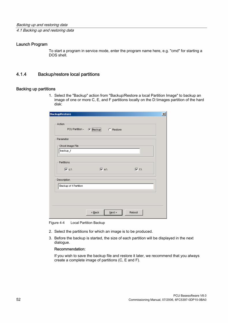
Backing up and restoring data 4.1 Backing up and restoring data
PCU Basesoftware V8.0 52 Commissioning Manual, 07/2006, 6FC5397-0DP10-0BA0
Launch Program To start a program in service mode, enter the program name here, e.g. "cmd" for starting a DOS shell.
4.1.4 Backup/restore local partitions
Backing up partitions 1. Select the "Backup" action from "Backup/Restore a local Partition Image" to backup an
image of one or more C, E, and F partitions locally on the D:\Images partition of the hard disk:
Figure 4-4 Local Partition Backup
2. Select the partitions for which an image is to be produced. 3. Before the backup is started, the size of each partition will be displayed in the next
dialogue. Recommendation: If you wish to save the backup file and restore it later, we recommend that you always create a complete image of partitions (C, E and F).

Backing up and restoring data 4.1 Backing up and restoring data
PCU Basesoftware V8.0 Commissioning Manual, 07/2006, 6FC5397-0DP10-0BA0 53
Restoring partitions Select the "Restore" action from "Backup/Restore a local Partition Image" to restore an image of one or more C, E, and F partitions locally from the D:\Images partition:
Restore the Rollback Image To restore the most recently saved image, namely the current image ("Rollback Image"), select "Restore the Rollback Image". The "Rollback Image" is the last created back-up of a partition.
4.1.5 Backing up/restoring the hard disk
Backing up the hard disk Select "Backup/Restore a Disk Image" to backup an image of the hard disk using the network connection:
Figure 4-5 Backup hard disk via the network
1. In order to establish a network connection with access to a released drive, select "Add Network Drive" and specify the name of the file for "Image File Name."
2. Under "Share," enter the computer name and the released directory. 3. To receive access privileges, enter a user name and password.

Backing up and restoring data 4.1 Backing up and restoring data
PCU Basesoftware V8.0 54 Commissioning Manual, 07/2006, 6FC5397-0DP10-0BA0
Figure 4-6 Drive Connection
4. Under "Options," select whether the disk image that is to be created is divided into several files of a certain size, so that these files can fit on one CD.
Restoring a hard disk Select the "Restore" action from "Backup/Restore Disc Image" to restore an image. Click "Next>" to be prompted:
See also Requirements (Page 57)
4.1.6 Restoring system data from "Emergency Image"
Restoring system data Select "Restore the Emergency Image", to restore the emergency image. This image must contain the back-up of partition E and can also contain a back-up of partitions C, D or F. It is provided in the event that only the system on partition E: is defective. The user data on partition F: are kept in the current status.
Caution The reading in of an "Emergency Image" from partition E: can only take place if no additional software has been installed or configured after this back up is created or the registry entries of all the applications that are on partition F: must be included in the image. Use the "Image Organizer" function only to identify an image as an emergency image that fulfills these conditions.
To restore the system data with "Emergency Image", the PCU must be booted from the service system (EBS).

Backing up and restoring data 4.2 Saving the HMI Advanced environment
PCU Basesoftware V8.0 Commissioning Manual, 07/2006, 6FC5397-0DP10-0BA0 55
Manage images Select “Image Organizer” to mark out one image contained in the displayed list as the emergency image, or to delete an existing image.
See also Creating the service system for PCU (Page 55)
4.2 Saving the HMI Advanced environment
Setting the original SINUMERIK HMI environment The "Original SINUMERIK HMI Environ" function is available as a script file on the service desktop. The original delivery condition is set up, i.e., the contents of the directories below are saved, when this function is executed: • C:\RUNOEM • F:\ADD_ON • F:\OEM • F:\USER Then the directories are cleared.
Setting the current SINUMERIK HMI environment The "Current SINUMERIK HMI Environ" function is available as a script file on the service desktop. When this function is executed, restoration of the original settings is canceled, i.e., the saved directory contents are copied back.
4.3 Creating the service system for PCU
Use In case servicing is needed, create a portable service system as an "Emergency Boot System" (EBS) on a USB memory store on the basis of WinPE. Recommendation: Preferably, the SIMATIC PC USB-FlashDrive with 512 MB storage capacity should be used.
Creating a service system The Ghost image is available on the hard disk under D:\Eboot in order to create the service system for a PCU 50.3 on a USB memory store. Please proceed as follows:

Backing up and restoring data 4.3 Creating the service system for PCU
PCU Basesoftware V8.0 56 Commissioning Manual, 07/2006, 6FC5397-0DP10-0BA0
1. Start the PCU 50.3 in the service mode. 2. Plug a USB memory store with at least 256 MB into one of the four USB ports of the
PCU 50.3. 3. Launch Ghost32.exe in directory E:\Tools 4. Select Ghost: Local → Disk → From Image. As the source, select D:\Eboot\eboot.gho and
as the destination select the USB memory store (recognizable by its storage capacity). Results: After successfully transferring eboot.gho to the USB memory store, the service system for the PCU is ready to use.
Using the same procedure, create a service system on a PG/PC. For this, the Symantec Ghost program must be installed on the PG/PC.
Booting up the service system 1. Plug the EBS into one of the rear USB ports of the PCU 50.3. 2. Press the <ALARM CANCEL> key on the operator panel or the <ESC> key on an
external keyboard while the BIOS of the PCU 50 is booting up in order to display the "Boot Menu".
3. Select the entry "USB-HDD: XXX " from the list of available media. Results: The PCU boots up from the service system and the ServiceCenter starts.
4. First select "Start" to start the ServiceCenter and then "Backup/Restore Disk Image", to restore the hard disk using the disk image.
Notice During booting: • The boot-up of the PCU from the EBS via the front USB interface of a directly
connected OP is also possible but it is considerably slower (=USB V1.1; rear USB 2.0).
• It is not possible to boot up the PCU from the EBS via the USB interface of a TCU. • It is not possible to save network settings on the EBS. • The EBS is not capable of functioning if a DVI monitor is connected directly to the DVI
interface of the PCU 50.3. VGA mode is only possible via a DVI → VGA adapter.
See also Backing up/restoring the hard disk (Page 53)
Backing up and restoring data 4.4 Connecting a PG/PC to the PCU in the system network
PCU Basesoftware V8.0 Commissioning Manual, 07/2006, 6FC5397-0DP10-0BA0 57
4.4 Connecting a PG/PC to the PCU in the system network
Applications For the following applications, you need a connection in the system network between the PCU and a PG/PC: • To store a backup image from the hard disk of a PCU 50 on a PG/PC. • To restore a PCU 50 hard disk via the CD-ROM drive of a PG/PC. • To commission a replacement hard disk.
4.4.1 Requirements
Overview The following figures show the typical connection options in the system network: • PCU to "Eth 2" with service PG/PC, directly, using a crossed Ethernet cable • PCU to "Eth 2" with service PG/PC, via a switch, using an un-crossed Ethernet cable If you want to connect the service PG/PC via a company network (Eth 1), contact your network service center. Meaning of the connections:
○ Eth 1 as a DHCP client ● Eth 2 as a DHCP server ■ Eth 2 with a fixed IP address
Green connection Gray connection
Uncrossed Ethernet cable Crossed Ethernet cable (crossover)

Backing up and restoring data 4.4 Connecting a PG/PC to the PCU in the system network
PCU Basesoftware V8.0 58 Commissioning Manual, 07/2006, 6FC5397-0DP10-0BA0
Configuration with PG/PC directly to PCU
Figure 4-7 Connecting a PG directly to a PCU
Configuration with PG/PC and switch to PCU
Figure 4-8 Connecting a PG via a Switch to a PCU
Note If a PCU is switched off and on again without its own OP/TP including TCU, and if the PCU boot-up is supposed to take place from the service system (EBS), an external VGA monitor and keyboard are needed in order to operate the PCU.

Backing up and restoring data 4.4 Connecting a PG/PC to the PCU in the system network
PCU Basesoftware V8.0 Commissioning Manual, 07/2006, 6FC5397-0DP10-0BA0 59
Basic procedure On the PG/PC with Windows XP: • Connecting a PG/PC to a PCU 50.3 as per one of the configurations in the figures above. • The network protocol used is: TCP/IP.
TCP/IP is already pre-configured in the basic PCU software. • Setting up IP addresses on the same subnetwork. • Releasing a directory on the PG/PC for network access. On the PCU under WinPE: • Start the ServiceCenter under WinPE on the PCU 50.3. • Establish a network connection to the released directory of the PG/PC. • Using the "Backup" function, a ghost image of the PCU hard disk is saved in the released
directory of the PG/PC in the event of a need for service. • With the "Restore" function, the hard disk of the PCU 50.3 is restored from a ghost image
in the released directory of the PG/PC.
See also Backing up/restoring the hard disk (Page 53)

Backing up and restoring data 4.4 Connecting a PG/PC to the PCU in the system network
PCU Basesoftware V8.0 60 Commissioning Manual, 07/2006, 6FC5397-0DP10-0BA0
4.4.2 Procedure
Settings on a PG/PC with Windows XP On a PG/PC, the following settings must be made: 1. Select "Control Panel" → "Network Connections" → "Local Area Connection Properties",
then you will see the following dialogue box:
2. Check to see whether "File and Printer Sharing ..." is selected, so that directories can be released and then select "Internet Protocol (TCP/IP)".

Backing up and restoring data 4.4 Connecting a PG/PC to the PCU in the system network
PCU Basesoftware V8.0 Commissioning Manual, 07/2006, 6FC5397-0DP10-0BA0 61
3. Open the "Properties" dialogue box and select the option "Use the following IP address", in order to enter an IP address, such as 192.168.214.250 and the subnet screen form 255.255.255.0.
4. Select "Control Panel" → "System" → Register "Computer Name", in order to learn the computer name of the PCU 50: e.g. SIEMENS-ABC4711
5. Select "Control Panel" → "Folder Options" → "View" and activate "Use simple file sharing (Recommended)", to avoid problems with the release of the directory.
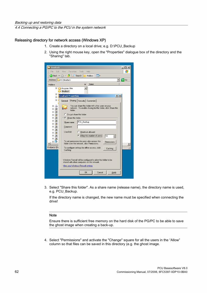
Backing up and restoring data 4.4 Connecting a PG/PC to the PCU in the system network
PCU Basesoftware V8.0 62 Commissioning Manual, 07/2006, 6FC5397-0DP10-0BA0
Releasing directory for network access (Windows XP) 1. Create a directory on a local drive; e.g. D:\PCU_Backup 2. Using the right mouse key, open the "Properties" dialogue box of the directory and the
"Sharing" tab.
3. Select "Share this folder". As a share name (release name), the directory name is used, e.g. PCU_Backup. If the directory name is changed, the new name must be specified when connecting the drive!
Note Ensure there is sufficient free memory on the hard disk of the PG/PC to be able to save the ghost image when creating a back-up.
4. Select "Permissions" and activate the "Change" square for all the users in the “Allow” column so that files can be saved in this directory (e.g. the ghost image.

Backing up and restoring data 4.4 Connecting a PG/PC to the PCU in the system network
PCU Basesoftware V8.0 Commissioning Manual, 07/2006, 6FC5397-0DP10-0BA0 63
Procedure on the PCU 50.3 The following steps must be carried out on the PCU: 1. Start the ServiceCenter with "Start Backup/Restore console". 2. Maintain the pre-setting of the "Network Options" on the PCU:
IP Address PCU 192.168.214.241 with subnet screen 255.255.255.0 IP Address PG/PC: 192.168.214.250 with subnet screen 255.255.255.0
3. In the ServiceCenter, select the service task "Backup/Restore a Disk Image". 4. Establish a network connection to the released directory, e.g. \\SIEMENS-
ABC4711\PCU_Backup. 5. Restore the hard disk of the PCU using the ghost image.
Note If the transfer is interrupted during the "Restore" process, no consistent system is available on the hard disk, i.e. the "Restore" process cannot be repeated because the PCU no longer boots up. In this event, the "Emergency Boot System" is used.
See also Backing up/restoring the hard disk (Page 53) Creating the service system for PCU (Page 55)
Backing up and restoring data 4.5 Commissioning the replacement hard disk
PCU Basesoftware V8.0 64 Commissioning Manual, 07/2006, 6FC5397-0DP10-0BA0
4.5 Commissioning the replacement hard disk
Overview The mechanical and electrical steps involved in replacing the PCU 50.3 hard disk are described in: References: Equipment manual "Operating Components"
Note The replacement hard disk is delivered without the Windows operating system and without HMI system software. The ServiceCenter incl. Symantec Ghost is installed at the factory on each PCU and on the replacement hard disk.
Creating a hard disk backup (disk image) The entire contents of hard disks can be saved as a disk image file using the Symantec Ghost utility. This "disk image" can be stored on various types of media for later restoration of the hard disk, e.g. on CD-ROM or a network drive.
Commissioning the replacement hard disk After installing the replacement hard disk, the Ethernet interfaces of the PCU are preset in the following manner: • Ethernet 1 (Company Network) as a standard DHCP client • Ethernet 2 (System Network) as a SINUMERIK DHCP server with the fixed IP address
192.168.214.241 and subnet screen 255.255.255.0 To commission the hard disk, proceed as follows: 1. Connect a PG/PC as per the recommended configurations. 2. Start the ServiceCenter and select "Restore Disk Image".
Note If the transfer is interrupted during the "Restore" process, no consistent system is available on the hard disk, i.e. the "Restore" process cannot be repeated because the PCU no longer boots up. In this event, the "Emergency Boot System" is used.

Backing up and restoring data 4.5 Commissioning the replacement hard disk
PCU Basesoftware V8.0 Commissioning Manual, 07/2006, 6FC5397-0DP10-0BA0 65
See also Requirements (Page 57) Backing up/restoring the hard disk (Page 53) Creating the service system for PCU (Page 55)

PCU Basesoftware V8.0 Commissioning Manual, 07/2006, 6FC5397-0DP10-0BA0 67
Service and diagnostics 55.1 PCU Hardware Diagnostics
Purpose The PCU hardware supports the diagnostics of important system components via an integrated "safecard", which is designated as a Safecard-On-Motherboard (SOM). These diagnostic functions are only evaluated by systems with HMI Advanced. The fault statuses of the hardware are reported in the form of alarms via the operator interface of HMI Advanced. This allows for visualization of the data in HMI Advanced and external evaluation.
Monitored Parameters The following physical parameters of the PCU 50.3 hardware are monitored: • CPU temperature • Housing temperature • I/O chip temperature • Speed of the two housing fans • S.M.A.R.T - status of the hard disk
Logging errors without HMI Advanced The PCU hardware monitor logs all hardware errors in the Windows event log so that the errors can be output even for a PCU without HMI Base installed. The alarms are output in the log under "Control Panel" → "Administrative Tools" → "Event Viewer".
Note The PLC interface of HMI Advanced is located in DB 10 of the PLC program and is supplied by the PCU hardware monitor in the event of a failure.
Service and diagnostics 5.2 Enabling/disabling error log during boot up
PCU Basesoftware V8.0 68 Commissioning Manual, 07/2006, 6FC5397-0DP10-0BA0
See also Description of the alarms: Diagnostics Manual SINUMERIK Replacement part description: Manual for Operating Components, Chapter PCU 50.3 Replacement Parts Commissioning the replacement hard disk (Page 64)
5.2 Enabling/disabling error log during boot up
Application Each time the system is booted up, information is written to a block in the file D:\$$Base.log, which contains the date, time and nature of administrative interventions. Information about the booting controlled by the HMI Manager, can be displayed on the screen and written to log file D:\$$Base.log.
Output in log file The output is controlled by registry values: • Type of information
The type of information to be output is set via registry value “HKLM\SOFTWARE\Siemens\SINUMERIK\Basic software\<version>\HMI Manager\InfoLevel”: InfoLevel (DWORD)
= 1: Mandatory information is output (default setting) = 2: Mandatory and supplementary information is output = 3: Mandatory, supplementary and trace information is output
(InfoLevel <= 0 is treated as InfoLevel == 1; InfoLevel <= 3 is treated as InfoLevel == 3)
• Outputting information to the screen
Whether the information is also to be displayed on the screen (as well as being output to the log file) is set via registry value 'HKLM\SOFTWARE\Siemens\SINUMERIK\Basic software\<version>\HMI Manager\ShowInfo': ShowInfo (DWORD)
= 0: Displays the mandatory information,
no display of the supplemental and trace information = 1: Mandatory, supplementary and trace information is displayed (default)
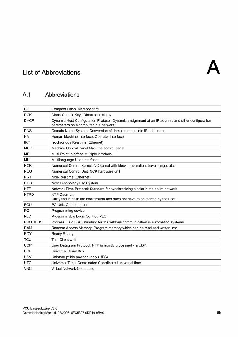
PCU Basesoftware V8.0 Commissioning Manual, 07/2006, 6FC5397-0DP10-0BA0 69
List of Abbreviations AA.1 Abbreviations CF Compact Flash: Memory card DCK Direct Control Keys Direct control key DHCP Dynamic Host Configuration Protocol: Dynamic assignment of an IP address and other configuration
parameters on a computer in a network DNS Domain Name System: Conversion of domain names into IP addresses HMI Human Machine Interface: Operator interface IRT Isochronous Realtime (Ethernet) MCP Machine Control Panel Machine control panel MPI Multi-Point Interface Multiple interface MUI Multilanguage User Interface NCK Numerical Control Kernel: NC kernel with block preparation, travel range, etc. NCU Numerical Control Unit: NCK hardware unit NRT Non-Realtime (Ethernet) NTFS New Technology File System NTP Network Time Protocol: Standard for synchronizing clocks in the entire network NTPD NTP Daemon:
Utility that runs in the background and does not have to be started by the user. PCU PC Unit: Computer unit PG Programming device PLC Programmable Logic Control: PLC PROFIBUS Process Field Bus: Standard for the fieldbus communication in automation systems RAM Random Access Memory: Program memory which can be read and written into RDY Ready Ready TCU Thin Client Unit UDP User Datagram Protocol: NTP is mostly processed via UDP. USB Universal Serial Bus USV Uninterruptible power supply (UPS) UTC Universal Time, Coordinated Coordinated universal time VNC Virtual Network Computing

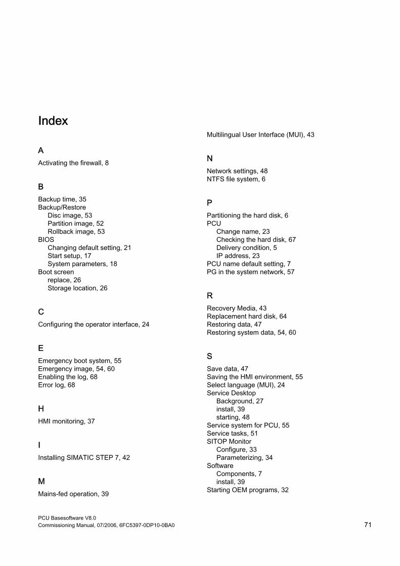
PCU Basesoftware V8.0 Commissioning Manual, 07/2006, 6FC5397-0DP10-0BA0 71
Index
A Activating the firewall, 8
B Backup time, 35 Backup/Restore
Disc image, 53 Partition image, 52 Rollback image, 53
BIOS Changing default setting, 21 Start setup, 17 System parameters, 18
Boot screen replace, 26 Storage location, 26
C Configuring the operator interface, 24
E Emergency boot system, 55 Emergency image, 54, 60 Enabling the log, 68 Error log, 68
H HMI monitoring, 37
I Installing SIMATIC STEP 7, 42
M Mains-fed operation, 39
Multilingual User Interface (MUI), 43
N Network settings, 48 NTFS file system, 6
P Partitioning the hard disk, 6 PCU
Change name, 23 Checking the hard disk, 67 Delivery condition, 5 IP address, 23
PCU name default setting, 7 PG in the system network, 57
R Recovery Media, 43 Replacement hard disk, 64 Restoring data, 47 Restoring system data, 54, 60
S Save data, 47 Saving the HMI environment, 55 Select language (MUI), 24 Service Desktop
Background, 27 install, 39 starting, 48
Service system for PCU, 55 Service tasks, 51 SITOP Monitor
Configure, 33 Parameterizing, 34
Software Components, 7 install, 39
Starting OEM programs, 32
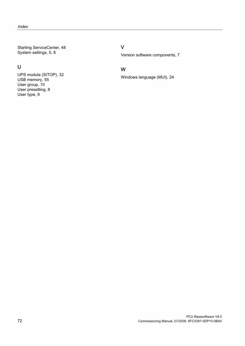
Index
PCU Basesoftware V8.0 72 Commissioning Manual, 07/2006, 6FC5397-0DP10-0BA0
Starting ServiceCenter, 48 System settings, 5, 8
U UPS module (SITOP), 32 USB memory, 55 User group, 10 User presetting, 8 User type, 9
V Version software components, 7
W Windows language (MUI), 24
Commissioning a system 1
Configuring the system 2
Installing software and network operation
3Backing up and restoring data
4SINUMERIK 810D/840Di/840D
PCU Basesoftware V7.6
Commissioning Manual
10/2006 6FC5397-0DP10-0BA0
Valid for: Software Version PCU Basesoftware 7.6
Safety Guidelines This manual contains notices you have to observe in order to ensure your personal safety, as well as to prevent damage to property. The notices referring to your personal safety are highlighted in the manual by a safety alert symbol, notices referring only to property damage have no safety alert symbol. These notices shown below are graded according to the degree of danger.
Danger
indicates that death or severe personal injury will result if proper precautions are not taken.
Warning
indicates that death or severe personal injury may result if proper precautions are not taken.
Caution
with a safety alert symbol, indicates that minor personal injury can result if proper precautions are not taken.
Caution
without a safety alert symbol, indicates that property damage can result if proper precautions are not taken.
Notice
indicates that an unintended result or situation can occur if the corresponding information is not taken into account.
If more than one degree of danger is present, the warning notice representing the highest degree of danger will be used. A notice warning of injury to persons with a safety alert symbol may also include a warning relating to property damage.
Qualified Personnel The device/system may only be set up and used in conjunction with this documentation. Commissioning and operation of a device/system may only be performed by qualified personnel. Within the context of the safety notes in this documentation qualified persons are defined as persons who are authorized to commission, ground and label devices, systems and circuits in accordance with established safety practices and standards.
Prescribed Usage Note the following:
Warning
This device may only be used for the applications described in the catalog or the technical description and only in connection with devices or components from other manufacturers which have been approved or recommended by Siemens. Correct, reliable operation of the product requires proper transport, storage, positioning and assembly as well as careful operation and maintenance.
Trademarks All names identified by ® are registered trademarks of the Siemens AG. The remaining trademarks in this publication may be trademarks whose use by third parties for their own purposes could violate the rights of the owner.
Disclaimer of Liability We have reviewed the contents of this publication to ensure consistency with the hardware and software described. Since variance cannot be precluded entirely, we cannot guarantee full consistency. However, the information in this publication is reviewed regularly and any necessary corrections are included in subsequent editions.
Siemens AG Automation and Drives Postfach 48 48 90437 NÜRNBERG GERMANY
Order No.: 6FC5397-0DP10-0BA0 Ⓟ 02/2007
Copyright © Siemens AG 2006. Technical data subject to change

PCU Basesoftware V7.6 Commissioning Manual, 10/2006, 6FC5397-0DP10-0BA0 3
Table of contents 1 Commissioning a system........................................................................................................................... 5
1.1 Delivery condition of the system ....................................................................................................5 1.1.1 Hard disk partitions ........................................................................................................................6 1.1.2 System settings..............................................................................................................................7 1.2 User administration ........................................................................................................................9 1.2.1 Which users are set up? ................................................................................................................9 1.2.2 Change service user ....................................................................................................................10 1.2.3 Global user settings .....................................................................................................................11 1.2.4 Specific user settings ...................................................................................................................14 1.3 Boot up behavior of the PCU .......................................................................................................15 1.3.1 Boot up of the PCU: no HMI program installed............................................................................15 1.3.2 Boot up of the PCU: HMI program already installed....................................................................16 1.4 BIOS settings ...............................................................................................................................17
2 Configuring the system ............................................................................................................................ 23 2.1 Service menu functions (DOS function).......................................................................................23 0 Parameterizing the service menu (DOS) ....................................................................................................25 2.1.2 Operating the main menu ............................................................................................................26 2.1.3 Setting the SINUMERIK HMI environment ..................................................................................27 2.1.4 Starting DOS shell and checking the software version................................................................29 2.1.5 Starting the service desktop.........................................................................................................30 2.1.6 Checking the hard disk ................................................................................................................31 2.2 Configuring the operator interface ...............................................................................................31 2.2.1 Storage location of HMI boot screen ...........................................................................................31 2.2.2 Displaying your own boot screen.................................................................................................32 2.2.3 Changing the background of the service desktop........................................................................33 2.3 User-specific settings during boot up...........................................................................................34 2.3.1 Starting an HMI program during boot up .....................................................................................34 2.3.2 Starting service des ktop during boot up ......................................................................................36 2.3.3 Starting OEM programs ...............................................................................................................38 2.3.4 Enabling/disabling error log during boot up .................................................................................39 2.4 PCU with SITOP UPS module .....................................................................................................40 2.4.1 Starting and configuring the SITOP monitor ................................................................................41 2.4.2 Configuration of the SITOP UPS module ....................................................................................42 2.4.3 Configuration for exiting the HMI .................................................................................................45
3 Installing software and network operation................................................................................................ 47 3.1 Installing software and software update ......................................................................................47 3.1.1 Installing an upgrade or Service Pack .........................................................................................47 3.1.2 “Silently” installing an upgrade or Service Pack ..........................................................................48 3.1.3 Installation with FAT16 data file structure....................................................................................50 3.1.4 Installation with FAT32 data file structure....................................................................................52 3.1.5 Installation via network connection ..............................................................................................53
Table of contents
PCU Basesoftware V7.6 4 Commissioning Manual, 10/2006, 6FC5397-0DP10-0BA0
3.2 Settings for network drives.......................................................................................................... 58 3.3 Network operation with the Service desktop............................................................................... 64 3.3.1 Installing and authorizing SIMATIC STEP 7 ............................................................................... 65 3.3.2 Authorizing SIMATIC STEP 7 via the Service menu .................................................................. 66
4 Backing up and restoring data ................................................................................................................. 69 4.1 Backing up/restoring data with an Ethernet connection.............................................................. 69 4.1.1 Backing up the PCU hard disk to the PG/PC hard disk .............................................................. 69 4.1.2 Restoring the PCU hard disk from the PG/PC hard disk ............................................................ 73 4.1.3 Commissioning a replacement hard disk .................................................................................... 79 4.2 Backing up and restoring PCU partitions locally ......................................................................... 81 4.2.1 Backing up partitions................................................................................................................... 83 4.2.2 Restoring partitions ..................................................................................................................... 85 4.2.3 Restoring Partition E: (Windows) on the PCU ............................................................................ 87 4.2.4 Deleting the backup image.......................................................................................................... 88 4.2.5 Defining an emergency backup image........................................................................................ 90 4.2.6 Restoring the emergency backup on partition E: ........................................................................ 92 4.3 Backing up/restoring data with a TCU configuration................................................................... 93
Index........................................................................................................................................................ 97

PCU Basesoftware V7.6 Commissioning Manual, 10/2006, 6FC5397-0DP10-0BA0 5
Commissioning a system 11.1 Delivery condition of the system
Overview The high-performance SINUMERIK PCU 50 features interfaces for communication via Ethernet and PROFIBUS DP/MPI, leaving the integrated slots free for other tasks. The USB port at the back of the device provides "hot plug and play" functionality for a standard PC keyboard and mouse. The SINUMERIK PCU 50 is shipped with the Windows XP ProEmbSys operating system and the Ghost backup software, versions 6 and 7. The HMI-Advanced user interface software can be ordered additionally. References: "Operator Components" Manual
Supplied software on the PCU The software installed on delivery of the PCU includes the components below, among others:
MS Windows XP Professional SP2 Internet Explorer V 6.0 MPI driver V 6.03 Symantec Ghost (incl. Ghost Explorer) V 7.0 (default) NFS client The NFS client from “Windows Services for UNIX“ is
installed on E:\SFU\NFSCLIENT.
Note For the system component versions contained in the PCU Basesoftware, see the C:\BaseVers.txt file. The software package "PCU Basesoftware Thin Client" is not included and must be ordered and installed separately.
Documentation for all Ghost tools is supplied on the PCU’s hard disk under E:\TOOLS.

Commissioning a system 1.1 Delivery condition of the system
PCU Basesoftware V7.6 6 Commissioning Manual, 10/2006, 6FC5397-0DP10-0BA0
1.1.1 Hard disk partitions
Division of the hard disk The hard disk is divided into a primary partition C and an extended partition containing the three logical drives D, E and F. Partitions C and D work with FAT16 file access and drives E and F with NTFS file access. The hard-disk partitioning corresponds to the grouping that is required for installing the HMI system software onto the PCU under Windows XP. Windows XP can be used with PCU 50 V2 (566 MHz or 1.2 GHz, 10 GB or 40 GB hard disk). For reasons of data security, the HMI system software and the Windows XP system software are distributed on the different hard disk partitions. Depending on the order details, the HMI system software may be pre-loaded on delivery. It is installed subsequently by the customer the first time the system is booted up. The following figure shows how the hard disk of the PCU is used:
Figure 1-1 Partitioning of hard disk (example with 10 GB)
Content of the partitions The individual partitions are intended for the following data or already contain this data:
EMERGENCY (C:) Partition C contains DOS 6.2 together with the tools and scripts
created by the Service menu (e.g., Ghost). TMP (D:) Used for storing Ghost images (e.g., of the status on delivery) and
local backup images. Contains the installation directory where the software to be installed is first copied to from a remote PG/PC, prior to the actual installation procedure.
SYSTEM (E:) Reserved for the Windows XP software. The Windows XP software is available on the recovery media CD via network, in order to later install drivers or updates as needed.
USER (F:) For installing user programs. Applications such as HMI system software (incl. data storage and temporary data), STEP7, OEM applications for HMI, or customer-specific applications should only be installed here.

Commissioning a system 1.1 Delivery condition of the system
PCU Basesoftware V7.6 Commissioning Manual, 10/2006, 6FC5397-0DP10-0BA0 7
Notice All of the applications must be exclusively installed on USER (F:); even if these applications have a different drive set as the default drive in their installation path. The names EMERGENCY, TMP, SYSTEM, USER must not be changed; otherwise the "ServiceCenter" (see Section 4) will no longer function.
1.1.2 System settings
PCU default setting A PCU 50 V2 has one integrated Ethernet interface. This is preset as a default DHCP client for the address reference from a company network. A second additional Ethernet card must be installed with an Ethernet interface to connect this PCU to an NCU or a TCU.
Note If no fixed Internet address is set for the Ethernet "on-board" and no DHCP server is available on the network, a so-called APIPA address is assigned under Windows XP. Boot manager is extended by at least one minute (this is system-related and not an error on the part of the HMI Manager).
The software package "PCU Basesoftware Thin Client" must be installed on the PCU if the PCU 50 V2 is to be operated in a SINIUMERIK solution line network. When installing the 'PCU Basesoftware Thin Client' on the PCU 50 V2, the Ethernet interface on the additionally installed Ethernet card must be set according to application. References: Commissioning Manual Thin Client Configuration
Name of the PCU Upon delivery of the system, a unique computer name is generated which can be read out under: "Start" → "Settings" → "Control Panel" → "System", "Computer Name" tab.
Configuration of the operating system For safety reasons, Windows XP has been preset as follows: • The Autorun function is deactivated. • Automatic Windows Update is deactivated. • Monitoring and alerts for antivirus software and automatic update are deactivated. • Links used to call up Internet Explorer from the service desktop and the start menu are
removed.
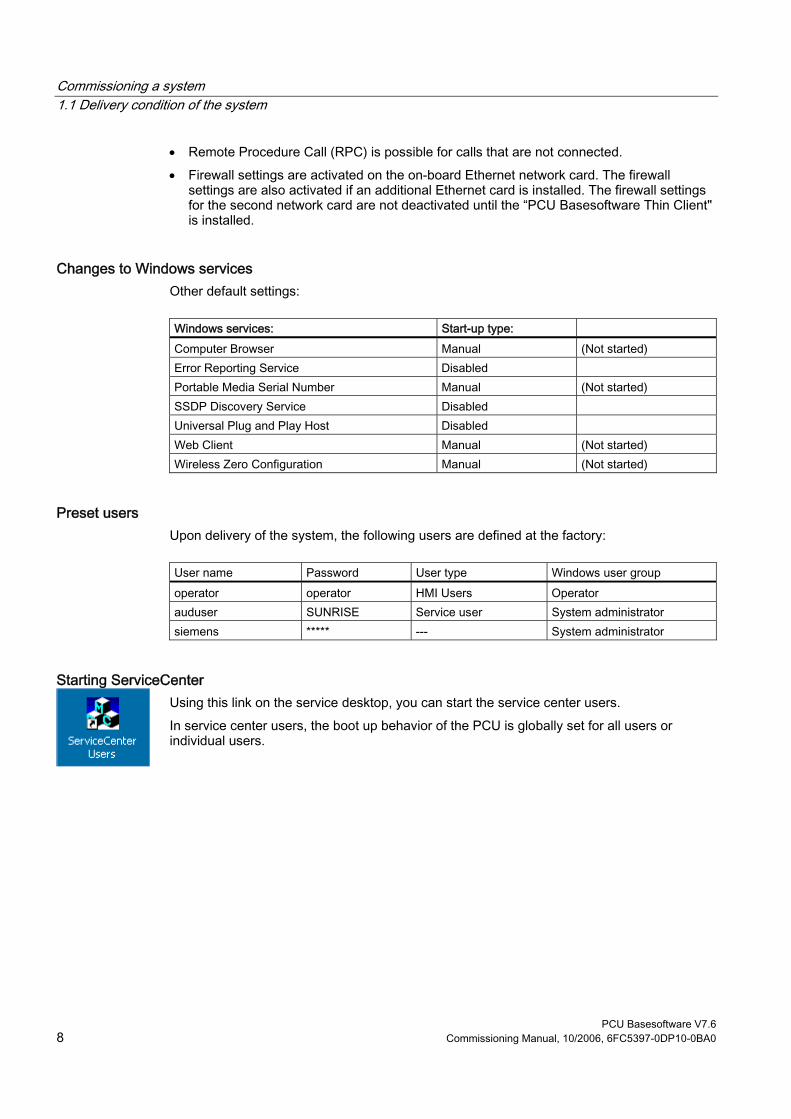
Commissioning a system 1.1 Delivery condition of the system
PCU Basesoftware V7.6 8 Commissioning Manual, 10/2006, 6FC5397-0DP10-0BA0
• Remote Procedure Call (RPC) is possible for calls that are not connected. • Firewall settings are activated on the on-board Ethernet network card. The firewall
settings are also activated if an additional Ethernet card is installed. The firewall settings for the second network card are not deactivated until the “PCU Basesoftware Thin Client" is installed.
Changes to Windows services Other default settings:
Windows services: Start-up type: Computer Browser Manual (Not started) Error Reporting Service Disabled Portable Media Serial Number Manual (Not started) SSDP Discovery Service Disabled Universal Plug and Play Host Disabled Web Client Manual (Not started) Wireless Zero Configuration Manual (Not started)
Preset users Upon delivery of the system, the following users are defined at the factory:
User name Password User type Windows user group operator operator HMI Users Operator auduser SUNRISE Service user System administrator siemens ***** --- System administrator
Starting ServiceCenter Using this link on the service desktop, you can start the service center users. In service center users, the boot up behavior of the PCU is globally set for all users or individual users.

Commissioning a system 1.2 User administration
PCU Basesoftware V7.6 Commissioning Manual, 10/2006, 6FC5397-0DP10-0BA0 9
1.2 User administration
1.2.1 Which users are set up?
Overview The users are managed in the "ServiceCenter Users", so that the commissioner/service user no longer has to make corresponding settings directly in the registry. The preset users are: • The "auduser".
The "auduser" is a service user type of user and belongs to the system administrators' user group. The system administrators have the user rights of a local administrator.
• The "operator" The "operator" is an HMI user type of user and belongs to the operators' user group. The operators have limited user rights.
For the HMI user and service user, individual settings can be configured for boot up, the HMI program and service.
Notice In the PCU Basesoftware version 7.6, only one service user ("auduser" is the default) and only one HMI user with the fixed name of "operator" are supported.
User Each user is from one user type and belongs to one user group.
User type A user can be assigned to the following user types:
User types Task card HMI Users • Boot up of the PCU
• Operating the HMI program Service user • Service tasks
• Boot up of the PCU • Operating the HMI program
The user types are implemented under Windows in user groups with various user rights.

Commissioning a system 1.2 User administration
PCU Basesoftware V7.6 10 Commissioning Manual, 10/2006, 6FC5397-0DP10-0BA0
User group The user types are implemented via the following Windows user groups:
User group Name of the group (Windows) User Rights Operator operator.group Restricted System administrators Administrators local administrator
Service Desktop The service desktop provides the service user with a Windows desktop, which is expanded by tools and functions for service tasks, such as manage users, install software, save/restore data, check system integrity, etc.
1.2.2 Change service user
Overview Any other Windows user can also become the service user (instead of “auduser”) if they are set up as a local Windows administrator or a domain user and possess local administrator rights.
Change service user The service user is identified in the registry by two entries: User name and user type. The default user name is "auduser", the user type for the service user is "2". In order to change the service user, the user who wants to be the new service user must log into Windows with local administrator rights. Only this user has sufficient user rights to make the entries in his user-specific branch of the registry. The service user is registered by the following registry entries:
Reference Default Key HKLM\SOFTWARE\Siemens\SINUMERIK\Basesoftware\<version>\HMIManager HMIUserName Entry <user name> (STRING) auduser HMIUserDomainName Entry <domain name> (STRING) (local)
Reference Default Key HKCU\SOFTWARE\Siemens\SINUMERIK\Basesoftware\HMIManager UserType Entry 2 (DWORD)
The following name must be entered under "HMIUserDomainName": • for a local administrator: (local) • for a domain operator: <domain name>

Commissioning a system 1.2 User administration
PCU Basesoftware V7.6 Commissioning Manual, 10/2006, 6FC5397-0DP10-0BA0 11
1.2.3 Global user settings
Principle of passing on In the "ServiceCenter Users", set the following responses under "Users" → "Global Settings": • Boot up behavior of the PCU • Start the HMI program • Behavior in service mode The settings that are made for users under "Global Settings" are passed on to individual users. The passed on settings can still be specifically adapted for the respective user. To do this, the user must log in using his password.
Figure 1-2 Global user settings
Startup:
Selection Effect Bitmap folder: - None - Directory with boot screens Default bitmap folder: F:\hmi_adv\ib\DATA\default Directory containing default boot screens Installing: "yes" (default) Installation privilege exists during boot up "no" No installation privilege
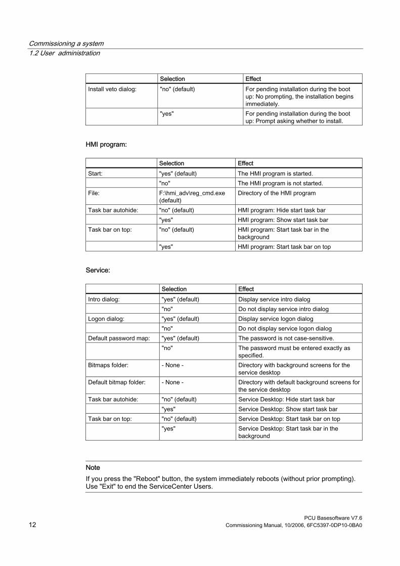
Commissioning a system 1.2 User administration
PCU Basesoftware V7.6 12 Commissioning Manual, 10/2006, 6FC5397-0DP10-0BA0
Selection Effect Install veto dialog: "no" (default) For pending installation during the boot
up: No prompting, the installation begins immediately.
"yes" For pending installation during the boot up: Prompt asking whether to install.
HMI program:
Selection Effect Start: "yes" (default) The HMI program is started. "no" The HMI program is not started. File: F:\hmi_adv\reg_cmd.exe
(default) Directory of the HMI program
Task bar autohide: "no" (default) HMI program: Hide start task bar "yes" HMI program: Show start task bar Task bar on top: "no" (default) HMI program: Start task bar in the
background "yes" HMI program: Start task bar on top
Service:
Selection Effect Intro dialog: "yes" (default) Display service intro dialog "no" Do not display service intro dialog Logon dialog: "yes" (default) Display service logon dialog "no" Do not display service logon dialog Default password map: "yes" (default) The password is not case-sensitive. "no" The password must be entered exactly as
specified. Bitmaps folder: - None - Directory with background screens for the
service desktop Default bitmap folder: - None - Directory with default background screens for
the service desktop Task bar autohide: "no" (default) Service Desktop: Hide start task bar "yes" Service Desktop: Show start task bar Task bar on top: "no" (default) Service Desktop: Start task bar on top "yes" Service Desktop: Start task bar in the
background
Note If you press the "Reboot" button, the system immediately reboots (without prior prompting). Use "Exit" to end the ServiceCenter Users.

Commissioning a system 1.2 User administration
PCU Basesoftware V7.6 Commissioning Manual, 10/2006, 6FC5397-0DP10-0BA0 13
Service dialogs during boot up The following dialogs are shown during boot up: • The Service Intro Dialog is shown, if no HMI program is installed or the start of the HMI
program is deactivated.
Figure 1-3 Service Intro Dialog
• If a service user wants to log in, the Service Logon Dialog is displayed: – After pressing key <3> during boot up. – After pressing the "Service" button in the service intro dialog.
Figure 1-4 Service Logon Dialog

Commissioning a system 1.2 User administration
PCU Basesoftware V7.6 14 Commissioning Manual, 10/2006, 6FC5397-0DP10-0BA0
1.2.4 Specific user settings
Passing on settings The settings that are made for users under "Global Settings" are passed on to the respective user.
Example: "operator" After the password is entered, the settings can be user-specifically adapted. The settings that cannot be changed are displayed with a grey background.
Figure 1-5 User settings for the "operator"

Commissioning a system 1.3 Boot up behavior of the PCU
PCU Basesoftware V7.6 Commissioning Manual, 10/2006, 6FC5397-0DP10-0BA0 15
1.3 Boot up behavior of the PCU
1.3.1 Boot up of the PCU: no HMI program installed
Requirement No HMI program is installed during the PCU boot up.
Ramp-up phase
Figure 1-6 PCU bootup diagram (without HMI program)
Explanations: • If installation programs (such as HMI Advanced) are present in directory D:\Install, you
will be prompted during the first boot up as to whether the installation procedure should be started. After installation is completed, you need to restart the system. The installation can also be skipped and carried out later.

Commissioning a system 1.3 Boot up behavior of the PCU
PCU Basesoftware V7.6 16 Commissioning Manual, 10/2006, 6FC5397-0DP10-0BA0
• In the service intro dialog, you can choose between "service" or "shutdown". • Selecting "service" opens the service logon dialog.
Note During the initial boot up of the PCU 50.3, the user can only log on as 'auduser'.
1.3.2 Boot up of the PCU: HMI program already installed
Requirement An HMI program (e.g. HMI Advanced) is already installed.
Ramp-up phase
Figure 1-7 PCU bootup diagram (HMI program installed)
Commissioning a system 1.4 BIOS settings
PCU Basesoftware V7.6 Commissioning Manual, 10/2006, 6FC5397-0DP10-0BA0 17
Explanations: • If the HMI program is already installed, the PCU boots up and the HMI program is started
(default). • During the boot up, there is a time interval for pressing key <3> when the version
information appears on the lower right of the background screen. The service logon dialog then opens.
• After logging in as a service user, you can either start the "service desktop" in order to carry out additional service tasks, or you can start the "ServiceCenter Users" in order to set the boot up behavior for the individual users.
1.4 BIOS settings
Overview The BIOS of the PCU is preset in such a way that no changes are required. The date and time can be set under Windows or the HMI operator interface.
Notice Your device configuration is preset for working with the software supplied with the unit. You should only change the preset values if you have modified your device in any way, or if a fault occurs when the unit is powered up.
Starting BIOS setup 1. Start the BIOS SETUP as follows:
Reset the device (warm or cold restart). After the first boot up, the following message appears: Press < F2 > to enter SETUP or <ESC> to show boot menu
2. Press the F2 key as long as the BIOS prompt appears on the screen.

Commissioning a system 1.4 BIOS settings
PCU Basesoftware V7.6 18 Commissioning Manual, 10/2006, 6FC5397-0DP10-0BA0
The BIOS main menu opens:
Figure 1-8 BIOS Main Menu (Example)
BIOS setup: Defaults The following system parameters are pre-stored on a PCU with 10 GB hard disk when it is shipped: Menu: Main
System parameters Defaults Custom entries System Time hh:mm:ss System Date MM/DD/YYYY Disk A 1.44 MB 3½" Primary Master 10056 MB Primary Slave None Secondary Master None Secondary slave None Memory Cache Write Back
Boot options QuickBoot Mode Enabled SETUP prompt Enabled POST errors Enabled

Commissioning a system 1.4 BIOS settings
PCU Basesoftware V7.6 Commissioning Manual, 10/2006, 6FC5397-0DP10-0BA0 19
Boot options Floppy check Disabled Diagnostic screen Enabled
Keyboard features Numlock Off Key click Disabled Keyboard auto-repeat rate 30 / sec Keyboard auto-repeat delay ½ sec
Hardware Options PCI MPI/DP Enabled On-board Ethernet Enabled Ethernet address 08 00 06 xx xx xx LAN Remote Boot Enabled Cardbus/PCMCIA slot Enabled Fan control Enabled SafeCard functions Enabled Legacy USB support Enabled CRT/LCD selection SIMULTANEOUS LCD screensize Expanded DSTN contrast 154 PS/2 mouse Auto Detect
Menu: Advanced
System parameters Defaults Custom entries COM/LPT1 Configuration Internal COM 1 Enabled Base I/O address 3F8 Interrupt IRQ 4 Internal COM 2 Enabled Base I/O address 2F8 Interrupt IRQ 3 Internal LPT 1 Enabled Mode EPP / Bi-directional
PCI Configuration PCI device slot 1 Option ROM scan Enabled Enable master Enabled Latency timer 0040h

Commissioning a system 1.4 BIOS settings
PCU Basesoftware V7.6 20 Commissioning Manual, 10/2006, 6FC5397-0DP10-0BA0
PCI Configuration PCI device slot 2 Option ROM scan Enabled Enable master Enabled Latency timer 0040h PCI device slot 3 Option ROM scan Enabled Enable master Enabled Latency timer 0040h PCI device slot 4 Option ROM scan Enabled Enable master Enabled Latency timer 0040h Ethernet Option ROM scan Disabled Enable master Disabled Latency timer 0040h
System parameters Defaults Custom entries PCI/PnP ISA IRQ Resource Exclusion IRQ 3 Available IRQ 4 Available IRQ 5 Available IRQ 7 Available IRQ 9 Available IRQ 10 Available IRQ 11 Reserved PCI IRQ Line 1 5 PCI IRQ Line 2 Auto-select PCI IRQ Line 3 Auto-select PCI IRQ Line 4 Auto-select Installed OS Other Reset configuration data No Floppy disk controller Enabled Local bus IDE adapter Both Large disk access mode DOS Memory gap at 15 MB Disabled Video Adapter Settings Frame Buffer Size 8 MB AGP Rate 4X Default primary video adapter AGP
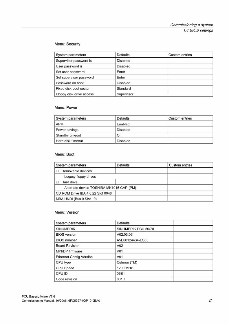
Commissioning a system 1.4 BIOS settings
PCU Basesoftware V7.6 Commissioning Manual, 10/2006, 6FC5397-0DP10-0BA0 21
Menu: Security
System parameters Defaults Custom entries Supervisor password is Disabled User password is Disabled Set user password Enter Set supervisor password Enter Password on boot Disabled Fixed disk boot sector Standard Floppy disk drive access Supervisor
Menu: Power
System parameters Defaults Custom entries APM Enabled Power savings Disabled Standby timeout Off Hard disk timeout Disabled
Menu: Boot
System parameters Defaults Custom entries ⊟ Removable devices Legacy floppy drives ⊟ Hard drive Alternate device TOSHIBA MK1016 GAP-(PM) CD ROM Drive IBA 4.0.22 Slot 0048 MBA UNDI (Bus 0 Slot 19)
Menu: Version
System parameters Defaults SINUMERIK SINUMERIK PCU 50/70 BIOS version V02.03.06 BIOS number A5E00124434-ES03 Board Revision V02 MPI/DP firmware V01 Ethernet Config Version V01 CPU type Celeron (TM) CPU Speed 1200 MHz CPU ID 06B1 Code revision 001C
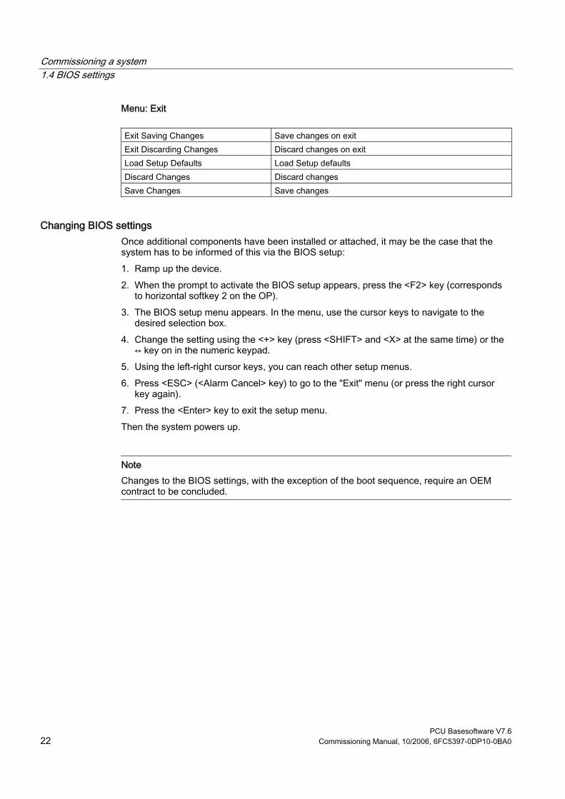
Commissioning a system 1.4 BIOS settings
PCU Basesoftware V7.6 22 Commissioning Manual, 10/2006, 6FC5397-0DP10-0BA0
Menu: Exit
Exit Saving Changes Save changes on exit Exit Discarding Changes Discard changes on exit Load Setup Defaults Load Setup defaults Discard Changes Discard changes Save Changes Save changes
Changing BIOS settings Once additional components have been installed or attached, it may be the case that the system has to be informed of this via the BIOS setup: 1. Ramp up the device. 2. When the prompt to activate the BIOS setup appears, press the <F2> key (corresponds
to horizontal softkey 2 on the OP). 3. The BIOS setup menu appears. In the menu, use the cursor keys to navigate to the
desired selection box. 4. Change the setting using the <+> key (press <SHIFT> and <X> at the same time) or the
↔ key on in the numeric keypad. 5. Using the left-right cursor keys, you can reach other setup menus. 6. Press <ESC> (<Alarm Cancel> key) to go to the "Exit" menu (or press the right cursor
key again). 7. Press the <Enter> key to exit the setup menu. Then the system powers up.
Note Changes to the BIOS settings, with the exception of the boot sequence, require an OEM contract to be concluded.
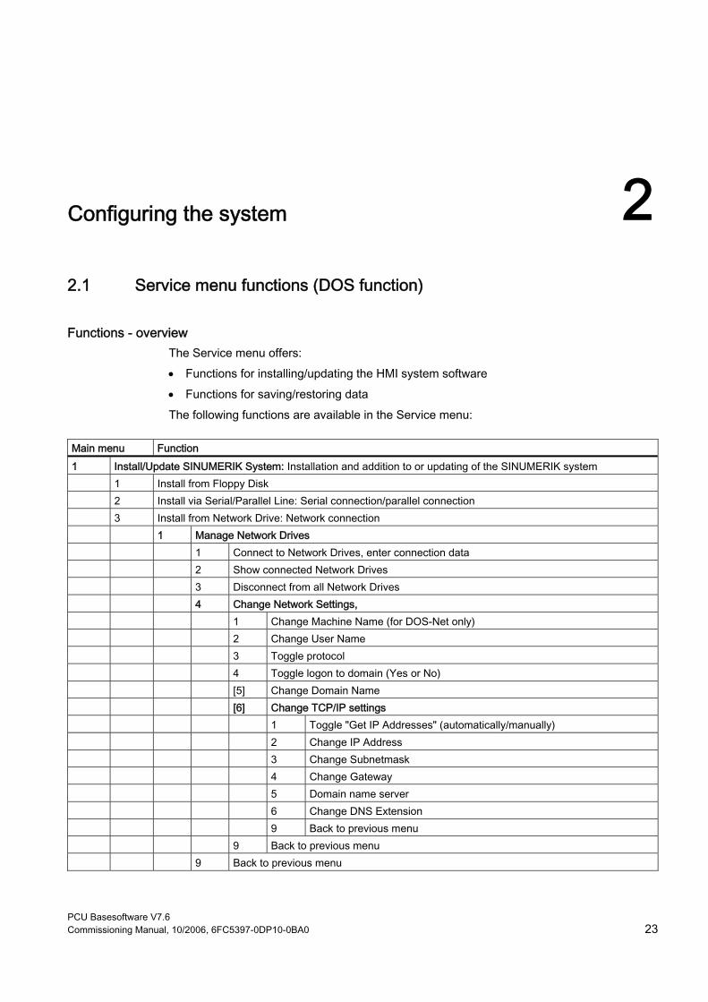
PCU Basesoftware V7.6 Commissioning Manual, 10/2006, 6FC5397-0DP10-0BA0 23
Configuring the system 22.1 Service menu functions (DOS function)
Functions - overview The Service menu offers: • Functions for installing/updating the HMI system software • Functions for saving/restoring data The following functions are available in the Service menu:
Main menu Function 1 Install/Update SINUMERIK System: Installation and addition to or updating of the SINUMERIK system 1 Install from Floppy Disk 2 Install via Serial/Parallel Line: Serial connection/parallel connection 3 Install from Network Drive: Network connection 1 Manage Network Drives 1 Connect to Network Drives, enter connection data 2 Show connected Network Drives 3 Disconnect from all Network Drives 4 Change Network Settings, 1 Change Machine Name (for DOS-Net only) 2 Change User Name 3 Toggle protocol 4 Toggle logon to domain (Yes or No) [5] Change Domain Name [6] Change TCP/IP settings 1 Toggle "Get IP Addresses" (automatically/manually) 2 Change IP Address 3 Change Subnetmask 4 Change Gateway 5 Domain name server 6 Change DNS Extension 9 Back to previous menu 9 Back to previous menu 9 Back to previous menu

Configuring the system 2.1 Service menu functions (DOS function)
PCU Basesoftware V7.6 24 Commissioning Manual, 10/2006, 6FC5397-0DP10-0BA0
Main menu Function 4 Change Install Directory [5] Install from (network drive), if set up 9 Back to previous menu 5 REBOOT: Restart of the system 9 Return to Main Menu: Back to main menu 2 SINUMERIK Tools and Options: Load additional tools and enable options. 1 Activate STEP7 for PCU 9 Return to Main Menu: Back to main menu 3 DOS Shell: Call the DOS command interpreter, drive C:\ is displayed, type "EXIT" to leave the DOS shell. 4 Start Windows: The Windows functions can be used here. 1 Standard Windows (without starting SINUMERIK HMI) 4 Original SINUMERIK HMI Environment, started on next ramp-up 5 Current SINUMERIK HMI Environment, started on next ramp-up 9 Return to Main Menu: Back to main menu 5 SINUMERIK System Check:Test the file system for consistency, restore consistency with SCANDISK if
necessary. 7 Backup/Restore: 1 Hard disk Backup/Restore with GHOST 1 Configure GHOST Parameters: Set parameters (interface, path, network connection) for Norton
Ghost 1 Set Connection Mode PARALLEL (LPT:) 2 Set Connection Mode LOCAL/NETWORK 3 Change Backup Image File Name 4 Change Restore Image File Name 5 Change Machine Name (for Windows and DOS net) 1 Input Machine Name MANUALLY 2 Generate Machine Name RANDOMLY 9 Back to previous Menu 6 Manage Network Drives 7 Change Split Mode 1 NO Splitting 2 Splitting 9 Back to previous Menu 2 Harddisk Backup: Backing up the hard disk 3 Harddisk Restore: Restore the data backup of the hard disk 1 Windows XP 1 Standard Partitioning (default) 2 User-defined Partitioning 3 Image-defined Partitioning 2 Windows NT/Windows 2000 (submenu same as for Windows XP) 3 Windows 95 (submenu same as for Windows XP) 4 WfW3.11 (submenu same as for Windows XP) 5 DOS (spare part) (submenu same as for Windows XP)

Configuring the system 2.1 Service menu functions (DOS function)
PCU Basesoftware V7.6 Commissioning Manual, 10/2006, 6FC5397-0DP10-0BA0 25
Main menu Function 9 Back to previous Menu 4 Switch to other version of GHOST 9 Back to previous Menu: Return to previous menu 4 Partitions Backup/Restore with Ghost: Back up partition contents of C:, E:, F: to D: or copy from D: back to
C:, E:, F:. 1 Configure GHOST Parameters 1 Change Maximum Backup Images 2 Define Emergency Backup Image 9 Back to previous Menu 2 Partitions Backup, Mode LOCAL 3 Partitions Restore, Mode LOCAL 4 Partition E (Windows) Restore, Mode LOCAL 8 Delete Image 9 Back to previous Menu 9 Return to Main Menu: Back to main menu 8 Start PC Link: Install software from a CD-ROM (Interlink/Interserve) 9 Reboot: System restart
2.1.1 Parameterizing the service menu (DOS)
Parameterizing the service menu The points available in the Service menu can be parameterized as follows:
[a] provide/suppress [b] observe special product designation (in place of SINUMERIK) [c] change text
File "envparam.bat" must be created in directory C:\Tools, and filled with the commands below for parameterization purposes:
Entry no. DOS command Text/function, if =TRUE Text/function, if
= FALSE Preassignment
1 [a] set _INSTALL 1 Install/Update SINUMERIK System
Not displayed TRUE
2 [a] set _TOOLS 2 SINUMERIK Tools and Options Not displayed TRUE 4 [a] set _SERVICE 4 Start Windows (Service Mode) Not displayed TRUE 6 [a] set _REBOOT 6 Reboot System (Warmboot) Not displayed FALSE [a] set _HMI Display submenu with HMI functions Not displayed TRUE String entries: 9 [c] set _ENDTXT =String Restart (warm boot) [b] set _PRODUCTLINE =String SINUMERIK
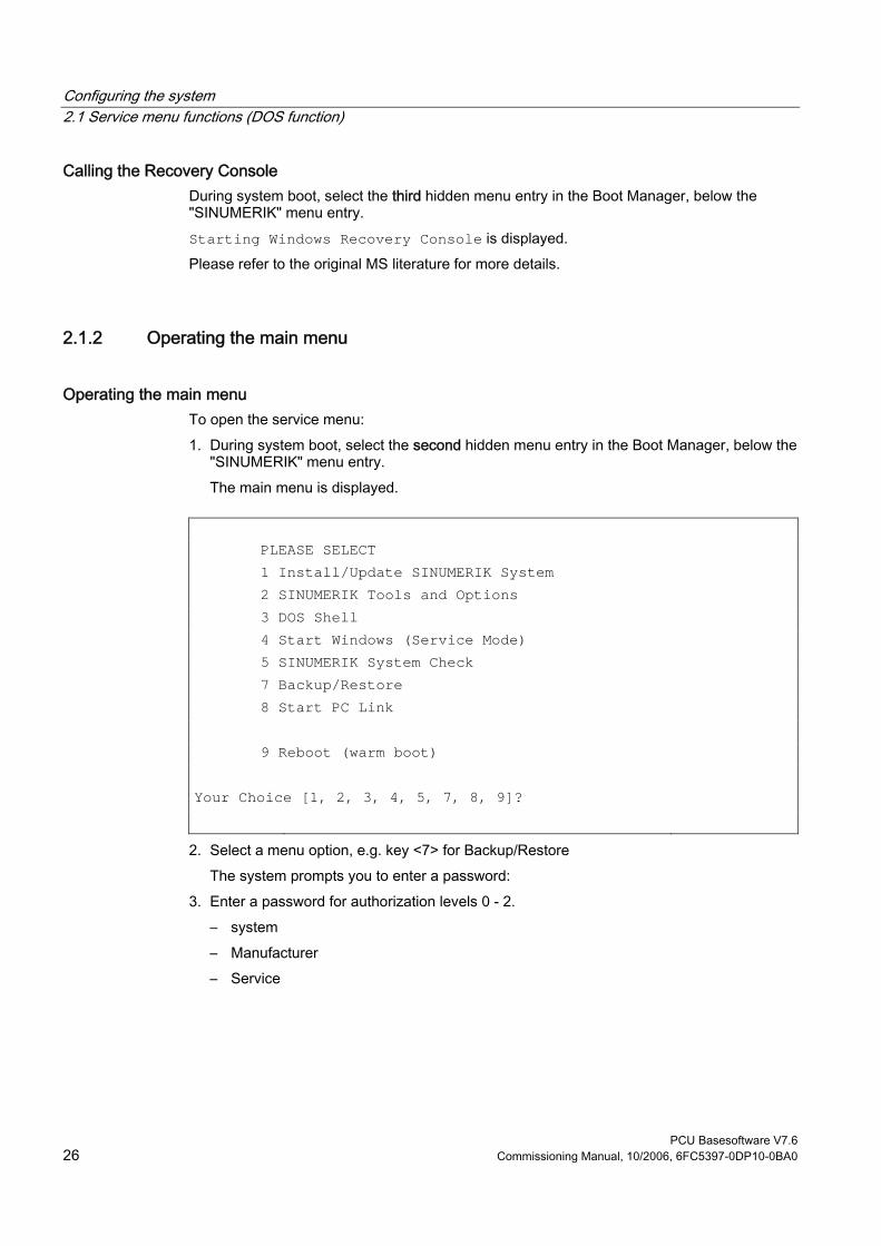
Configuring the system 2.1 Service menu functions (DOS function)
PCU Basesoftware V7.6 26 Commissioning Manual, 10/2006, 6FC5397-0DP10-0BA0
Calling the Recovery Console During system boot, select the third hidden menu entry in the Boot Manager, below the "SINUMERIK" menu entry. Starting Windows Recovery Console is displayed. Please refer to the original MS literature for more details.
2.1.2 Operating the main menu
Operating the main menu To open the service menu: 1. During system boot, select the second hidden menu entry in the Boot Manager, below the
"SINUMERIK" menu entry. The main menu is displayed.
PLEASE SELECT 1 Install/Update SINUMERIK System 2 SINUMERIK Tools and Options 3 DOS Shell 4 Start Windows (Service Mode) 5 SINUMERIK System Check 7 Backup/Restore 8 Start PC Link 9 Reboot (warm boot) Your Choice [1, 2, 3, 4, 5, 7, 8, 9]?
2. Select a menu option, e.g. key <7> for Backup/Restore The system prompts you to enter a password:
3. Enter a password for authorization levels 0 - 2. – system – Manufacturer – Service
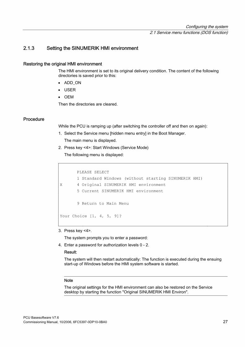
Configuring the system 2.1 Service menu functions (DOS function)
PCU Basesoftware V7.6 Commissioning Manual, 10/2006, 6FC5397-0DP10-0BA0 27
2.1.3 Setting the SINUMERIK HMI environment
Restoring the original HMI environment The HMI environment is set to its original delivery condition. The content of the following directories is saved prior to this: • ADD_ON • USER • OEM Then the directories are cleared.
Procedure While the PCU is ramping up (after switching the controller off and then on again): 1. Select the Service menu [hidden menu entry] in the Boot Manager.
The main menu is displayed. 2. Press key <4>: Start Windows (Service Mode)
The following menu is displayed:
PLEASE SELECT 1 Standard Windows (without starting SINUMERIK HMI) X 4 Original SINUMERIK HMI environment 5 Current SINUMERIK HMI environment 9 Return to Main Menu Your Choice [1, 4, 5, 9]?
3. Press key <4>. The system prompts you to enter a password:
4. Enter a password for authorization levels 0 - 2. Result: The system will then restart automatically: The function is executed during the ensuing start-up of Windows before the HMI system software is started.
Note The original settings for the HMI environment can also be restored on the Service desktop by starting the function "Original SINUMERIK HMI Environ".

Configuring the system 2.1 Service menu functions (DOS function)
PCU Basesoftware V7.6 28 Commissioning Manual, 10/2006, 6FC5397-0DP10-0BA0
Restoring the current HMI environment The original HMI environment setting is undone, that is, the contents of the saved directories are reloaded.
Procedure While the PCU is ramping up (after switching the controller off and then on again): 1. Select the Service menu [hidden menu entry] in the Boot Manager.
The main menu is displayed: 2. Press key <4>: Start Windows (Service Mode)
The following menu is displayed:
PLEASE SELECT 1 Standard Windows (without starting SINUMERIK HMI) 4 Original SINUMERIK HMI environment X 5 Current SINUMERIK HMI environment 9 Return to Main Menu Your Choice [1, 4, 5, 9]?
3. Press key <5>. The system will ask you to enter the password:
4. Enter one of the passwords for authorization levels 0 - 2. Result: The system will then restart automatically: The function is executed during the ensuing start-up of Windows before the HMI system software is started.
Note Restoration of the original settings for the HMI environment can also be canceled on the Service desktop by starting the function "Current SINUMERIK HMI Environ".
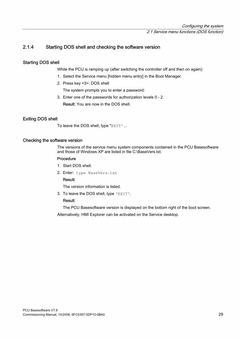
Configuring the system 2.1 Service menu functions (DOS function)
PCU Basesoftware V7.6 Commissioning Manual, 10/2006, 6FC5397-0DP10-0BA0 29
2.1.4 Starting DOS shell and checking the software version
Starting DOS shell While the PCU is ramping up (after switching the controller off and then on again): 1. Select the Service menu [hidden menu entry] in the Boot Manager. 2. Press key <3>: DOS shell
The system prompts you to enter a password: 3. Enter one of the passwords for authorization levels 0 - 2.
Result: You are now in the DOS shell.
Exiting DOS shell To leave the DOS shell, type "EXIT"..
Checking the software version The versions of the service menu system components contained in the PCU Basesoftware and those of Windows XP are listed in file C:\BaseVers.txt. Procedure 1. Start DOS shell. 2. Enter: type BaseVers.txt
Result: The version information is listed.
3. To leave the DOS shell, type "EXIT". Result: The PCU Basesoftware version is displayed on the bottom right of the boot screen.
Alternatively, HMI Explorer can be activated on the Service desktop.

Configuring the system 2.1 Service menu functions (DOS function)
PCU Basesoftware V7.6 30 Commissioning Manual, 10/2006, 6FC5397-0DP10-0BA0
2.1.5 Starting the service desktop
Purpose On the next ramp-up, the Service desktop (Windows) will start instead of the HMI system software.
Procedure While the PCU is ramping up (after switching the controller off and then on again): 1. Select the Service menu [hidden menu entry] in the Boot Manager.
The main menu is displayed. 2. Press key <4>: Start Windows (Service Mode)
The following menu appears:
PLEASE SELECT X 1 Standard Windows (without starting SINUMERIK HMI) 4 Original SINUMERIK HMI environment 5 Current SINUMERIK HMI environment 9 Return to Main Menu Your Choice [1, 4, 5, 9]?
3. Press key <1>: Result: The system will then restart automatically: The Service desktop (Windows) is started instead of the HMI system software.
Note The Service desktop can also be launched by pressing key <3> within 3 seconds of the version details of the PCU Basesoftware appearing in the background when booting.
Configuring the system 2.2 Configuring the operator interface
PCU Basesoftware V7.6 Commissioning Manual, 10/2006, 6FC5397-0DP10-0BA0 31
2.1.6 Checking the hard disk
Purpose All partitions (C:, D:, E:, F:) on the hard disk are checked.
Procedure While the PCU is ramping up (after switching the controller off and then on again) 1. Select the Service menu [hidden menu entry] in the Boot Manager
The main menu is displayed. 2. Press key <5>: SINUMERIK System Check
Result: The system will then restart automatically: The function is executed during the ensuing start-up of Windows before the HMI system software is started.
Note The hard disk can also be checked on the Service desktop by starting the function "Check SINUMERIK System".
2.2 Configuring the operator interface
2.2.1 Storage location of HMI boot screen
Default setting The Siemens boot screens are stored under the path below on the appropriate PCU, e.g., for the SINUMERIK 840D controller: F:\hmi_adv\ib\DATA\0\0\<Auflösung>\0_0.bmp A directory tree can also be created for manufacturer-specific boot screens. The manufacturer’s screens can then be saved in accordance with the schematic below.

Configuring the system 2.2 Configuring the operator interface
PCU Basesoftware V7.6 32 Commissioning Manual, 10/2006, 6FC5397-0DP10-0BA0
Directory tree of manufacturer-specific boot screens: F:\oem\ib\DATA\<NckType>\<Resolution>\<Name>.bmp
<NckType> stands for:
0 840D 2000 810D 5000 840Di
<Resolution>: 640 or 800 or 1024 dpi If you want the same screen to be used each time (NCU-independent screen), it can be saved in the "default" directory in the required resolutions. If you want to be able to use different screens for different NCUs, they should be saved in the <NckType>\<Resolution> subdirectories using the appropriate resolution.
Screen name and resolution <Name>.bmp: The name can be selected freely; only one file is permitted per directory. The screens must be created with a graphics tool in the resolution indicated by the subdirectory name and stored in the corresponding directory. The HMI software selects the screen, depending on the NCK type and the resolution of the available operator panel.
2.2.2 Displaying your own boot screen
Requirements Set up a directory containing several boot screens (for different panel resolutions). This directory should be segmented into subdirectories 640, 800 and 1024, which each contain a boot screen of the appropriate resolution. A directory containing boot screens can also be set up, likewise divided into subdirectories 640, 800 and 1024. The boot screen stored there for a particular resolution is displayed if no boot screen (including one with a lower resolution) is found in the booting-screen directory described above. If no boot screen (including one with a lower resolution) is found, a general boot screen is displayed, which is part of the PCU basic software.
Directories The directories can be user-specifically set in ServiceCenter Users under: • Startup: Bitmaps folder • Startup: Default bitmap folder

Configuring the system 2.2 Configuring the operator interface
PCU Basesoftware V7.6 Commissioning Manual, 10/2006, 6FC5397-0DP10-0BA0 33
2.2.3 Changing the background of the service desktop
Overview A background pattern for the service desktop is not set via the "Control Panel" (system control), but in the registry: • Background pattern:
Key: HKLM\SOFTWARE\Siemens\SINUMERIK\Basic software\ <version>\HMI desktop Value: Pattern (STRING) Date: <bit code>” (e.g., “0 80 114 32 0 5 39 2”, see HKCU\Control Panel\Patterns)
“(None)” (= NO background pattern) Init data: Background pattern previously set via the Control Panel Default data:
“(None)” (if entry is not available/readable)
• Background image:
A background screen for the service desktop is not user-specifically set via the "Control Panel" (system control), but in the ServiceCenter Users under "Service: Bitmap Folders" or "Service: Default Bitmap Folders".
Note An attempt to set the service desktop background (as in standard Windows) via the Control Panel does not affect the service desktop background display, but only the boot screen display.

Configuring the system 2.3 User -specific settings during boot up
PCU Basesoftware V7.6 34 Commissioning Manual, 10/2006, 6FC5397-0DP10-0BA0
2.3 User-specific settings during boot up
Overview If an HMI program, e.g., HMI Advanced, is to be started following booting, the settings and functionality differ from those that apply if the service desktop is to be started.
2.3.1 Starting an HMI program during boot up
Filtering keys During boot up of an HMI program, keystroke sequences and pressed function keys are simultaneously filtered. The keystroke sequences and functions that were pressed simultaneously and are to be filtered can be configured in file E:\Windows\System.ini. Filtering keystroke sequences:
Section: MMC103Keyb Key: SeqAct Value: <bit mask>
(= keystroke sequences to be filtered, specified in accordance with the comment in E:\Windows\System.ini)
Init value: 262143
Filtering function keys that were pressed simultaneously:
Section: MMC103Keyb Key: ConcurrentKeyMask Value: <bit mask>
(= function keys to be filtered, specified in accordance with the comment in E:\Windows\System.ini)
Init value: 255

Configuring the system 2.3 User -specific settings during boot up
PCU Basesoftware V7.6 Commissioning Manual, 10/2006, 6FC5397-0DP10-0BA0 35
Starting additional programs Programs can also be started at the same time as the HMI program and are started automatically by Windows when the service desktop is opened. This start in parallel to the HMI program can be configured. If the programs to be started are located in the Windows directories of E:\Documents and Settings, the following registry entry must be set:
Key: HKLM\SOFTWARE\Siemens\SINUMERIK\Basic software\ <version>\HMI Manager Value: StartSINHMIStartupDirsPrograms (DWORD) Date: 1 (the programs are started) or
0 (the programs are NOT started) Init data: 0 Default data: 0 (if entry is not available/readable)
If the programs to be started are set in the registry entries 'HKCU\Software\Microsoft\Windows\CurrentVersion\Run' and 'HKLM\Software\Microsoft\Windows\CurrentVersion\Run', the following registry entry must be set:
Key: HKLM\SOFTWARE\Siemens\SINUMERIK\Basic software\ <version>\HMI
Manager Value: StartSINHMIRunPrograms (DWORD) Date: 1 (the programs are started) or
0 (the programs are NOT started) Init data: 0 Default data: 0 (if entry is not available/readable)
Executing an HMI program While the HMI program is being executed, Windows Explorer runs in the background and its settings (disabled browser functionality, taskbar, start menu, ...) prevent the Windows platform being accessed unintentionally. The behavior of the taskbar can be user-specifically set in the ServiceCenter Users under "HMI program" using "Taskbar Autohide" and "Taskbar On Top".
Ending an HMI program When the HMI program is ended, Windows XP shuts down completely.

Configuring the system 2.3 User -specific settings during boot up
PCU Basesoftware V7.6 36 Commissioning Manual, 10/2006, 6FC5397-0DP10-0BA0
2.3.2 Starting service des ktop during boot up
Filtering keys The keystroke sequences and function keys that are pressed simultaneously are filtered as a function of the configuration in file: E:\Windows\System.ini Filtering keystroke sequences:
Section: MMC103Keyb Key: KeySequencesEnable Value: 1 (= filtering of keystroke sequences specified in the SeqAct key) or
0 (= NO filtering) Init value: 0 Default value: 0 (if entry is not available/readable):
Key: SeqAct Value: <bit mask> (= keystroke sequences to be filtered, specified in accordance
with the comment in E:\Windows\System.ini) Init value: 262143
Filtering function keys that were pressed simultaneously:
Section: MMC103Keyb Key: ConcurrentKeyEnable Value: 1 (= filtering of function keys specified in the ConcurrentKeyMask key) or
0 (= NO filtering) Init value: 1 Default value: 0 (if entry is not available/readable)
Key: ConcurrentKeyMask Value: <bit mask> (= function keys to be filtered, specified in accordance with the
comment in E:\Windows\System.ini) Init value: 255
Starting the service desktop The Windows platform is freely accessible via the service desktop. When the service desktop is started, all of the programs that would automatically be started by Windows (standard version) during log-in are also started.
Executing an HMI program The HMI program can also be started from the service desktop.

Configuring the system 2.3 User -specific settings during boot up
PCU Basesoftware V7.6 Commissioning Manual, 10/2006, 6FC5397-0DP10-0BA0 37
Ending an HMI program When an HMI program started from the service desktop is exited, you are returned to the service desktop.
Saving the service desktop (default) The settings on the service desktop (e.g. arrangement of the links on the service desktop) are not saved when you log off. A service technician should always find the same starting condition on the service desktop, not the settings from a previous session.
Saving the settings of the service Desktop This behavior can be changed by making an entry in the registry. The following settings can be saved via this registry entry: • Positions of open windows • Size and position of the task bar • Moving and deleting links
Key: HKLM\SOFTWARE\Siemens\SINUMERIK\Basic software\ <version>\HMI
Manager Value: SaveSINDesktopSettings (DWORD) Date: 1 (the settings are saved) or
0 (the settings are NOT saved) Init data: - Value is not created by the basic software - Default data: 0 (if entry is not available/readable)
The key is effective for all service users and other users. Links on the service desktop are always saved, irrespective of the registry entry.
Note Application windows that are still open before logging out, must be closed by the setting "Save settings" before exiting the service desktop. Otherwise, these application windows will briefly be displayed and then closed again during a restart immediately before the HMI program starts.
Configuring the system 2.3 User -specific settings during boot up
PCU Basesoftware V7.6 38 Commissioning Manual, 10/2006, 6FC5397-0DP10-0BA0
2.3.3 Starting OEM programs
Overview You can start OEM programs directly before starting the HMI system software. This requires these programs (or their links) to be stored in subdirectories of the directory C:\RunOEM.
Starting sequence The subdirectories are executed in the order listed. The programs within a subdirectory are started in the chronological order in which they were placed in the subdirectory. • Programs in the C:\RunOEM\SeqOnce subdirectory are started once and sequentially,
i.e., a program is not started until the previously started program is completed. • Programs in the C:\RunOEM\Seq subdirectory are started sequentially whenever the
system is ramped up, i.e., a program is not started until the previously started program is completed.
• Programs in the C:\RunOEM\ParOnce subdirectory are started once and simultaneously. They run parallel with the HMI system software.
• Programs in the C:\RunOEM\Par subdirectory are started simultaneously whenever the system is ramped up. They run parallel with the HMI system software.
Not only program files, but also other types of file can be stored in the subdirectories, which are then opened in accordance with their file type. For example, ".txt" files are opened using Notepad, ".htm" files are opened using Internet Explorer.
Configuring the system 2.3 User -specific settings during boot up
PCU Basesoftware V7.6 Commissioning Manual, 10/2006, 6FC5397-0DP10-0BA0 39
2.3.4 Enabling/disabling error log during boot up
Application Each time the system is booted up, information is written to a block in the file D:\$$Base.log, which contains the date, time and nature of administrative interventions. Information about the booting controlled by the HMI Manager, can be displayed on the screen and written to log file D:\$$Base.log.
Output in log file The output is controlled by registry values: • Type of information
The type of information to be output is set via registry value “HKLM\SOFTWARE\Siemens\SINUMERIK\Basic software\<version>\HMI Manager\InfoLevel”: InfoLevel (DWORD)
= 1: Mandatory information is output (default setting) = 2: Mandatory and supplementary information is output = 3: Mandatory, supplementary and trace information is output
(InfoLevel <= 0 is treated as InfoLevel == 1; InfoLevel <= 3 is treated as InfoLevel == 3)
• Outputting information to the screen
Whether the information is also to be displayed on the screen (as well as being output to the log file) is set via registry value 'HKLM\SOFTWARE\Siemens\SINUMERIK\Basic software\<version>\HMI Manager\ShowInfo': ShowInfo (DWORD)
= 0: Displays the mandatory information,
no display of the supplemental and trace information = 1: Mandatory, supplementary and trace information is displayed (default)

Configuring the system 2.4 PCU with SITOP UPS module
PCU Basesoftware V7.6 40 Commissioning Manual, 10/2006, 6FC5397-0DP10-0BA0
2.4 PCU with SITOP UPS module
application If the supply voltage to the PCU 50/70 dips, the SITOP UPS modules below could maintain operation for a limited period if a backup battery is being used, allowing the PCU to be properly shut down before the battery is exhausted:
Designation Interface Order number 6A module USB 6EP1931-2DC41 15A module USB 6EP1931-2EC41 6A module Serial 6EP1931-2DC31 15A module Serial 6EP1931-2EC31
Note The UPS modules with USB interfaces can only be used on a PCU 50 with Windows XP PCU Basesoftware.
Requirements • Windows XP PCUBasesoftware, 07.03.02 or higher for serial interface or
Windows XP PCUBasesoftware, 07.04.00 or higher for USB interface • HMI Advanced, V06.03.14 or higher • SITOP software, V2.5.2.4 or higher is installed:
SITOP software is available for download from: www.ad.siemens.de/sitop • SITOP monitor/configuration program is installed:
To enable this, the SITOP software must be copied to the E:\SITOP directory set up on the PCU 50. This directory already contains PCU 50 tools required for shutdown on the SITOP UPS. If this directory does not exist in an older version of the PCU Basesoftware, it must be created so that it will be compatible for any subsequent updating of the PCU Basesoftware.
• UPS USB driver for Windows XP is installed: Installation is described in the relevant SITOP documentation. The documentation is part of the SITOP software download package.
• The SITOP UPS hardware is connected.
Test environment The "SITOP UPS" function has been tested in the standard configuration of HMI Advanced. When installing add-on or OEM software components, the shutdown procedure of the complete system has to be checked by the operator.
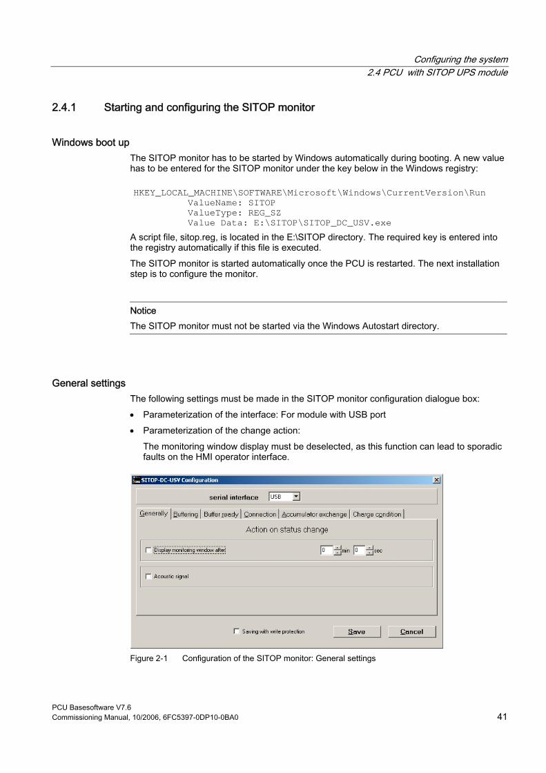
Configuring the system 2.4 PCU with SITOP UPS module
PCU Basesoftware V7.6 Commissioning Manual, 10/2006, 6FC5397-0DP10-0BA0 41
2.4.1 Starting and configuring the SITOP monitor
Windows boot up The SITOP monitor has to be started by Windows automatically during booting. A new value has to be entered for the SITOP monitor under the key below in the Windows registry:
HKEY_LOCAL_MACHINE\SOFTWARE\Microsoft\Windows\CurrentVersion\Run ValueName: SITOP
ValueType: REG_SZ Value Data: E:\SITOP\SITOP_DC_USV.exe
A script file, sitop.reg, is located in the E:\SITOP directory. The required key is entered into the registry automatically if this file is executed. The SITOP monitor is started automatically once the PCU is restarted. The next installation step is to configure the monitor.
Notice The SITOP monitor must not be started via the Windows Autostart directory.
General settings The following settings must be made in the SITOP monitor configuration dialogue box: • Parameterization of the interface: For module with USB port • Parameterization of the change action:
The monitoring window display must be deselected, as this function can lead to sporadic faults on the HMI operator interface.
Figure 2-1 Configuration of the SITOP monitor: General settings

Configuring the system 2.4 PCU with SITOP UPS module
PCU Basesoftware V7.6 42 Commissioning Manual, 10/2006, 6FC5397-0DP10-0BA0
Parameterization of the SITOP monitor Enter the path of the program that ensures that HMI Advanced and the PCU shut down properly in the event of a power failure into the parameter area of the buffer. E:\SITOP\Shutdown.bat
Figure 2-2 Configuration of the SITOP monitor: Buffering settings
Alternatively, the following setting can be used: E:\Windows\system32\hmiexit.exe
2.4.2 Configuration of the SITOP UPS module
Buffering parameterization The UPS module can be used to select whether buffering should be completed after a predetermined period of time or not until the accumulator’s lowest discharge threshold (= maximum buffer time) has been reached. Both buffering parameterizations result from this.
"Maximum buffer time" mode (PCUBasesoftware Windows XP, V07.04.00 or higher) This mode enables the system to be shut down in a time-optimized manner. The UPS module is synchronized with the shutdown of the operating system. Buffering is maintained until the operating system has been shut down. The operating system must shut down within a maximum of five minutes (including all applications). Otherwise, the UPS module buffers for the maximum buffer time (dependent on the accumulator state).
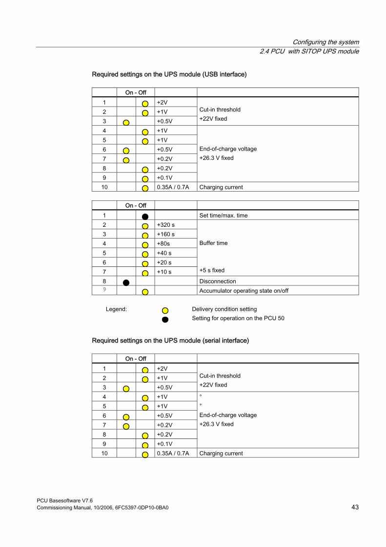
Configuring the system 2.4 PCU with SITOP UPS module
PCU Basesoftware V7.6 Commissioning Manual, 10/2006, 6FC5397-0DP10-0BA0 43
Required settings on the UPS module (USB interface)
On - Off 1 +2V 2 +1V 3 +0.5V
Cut-in threshold +22V fixed
4 +1V 5 +1V 6 +0.5V 7 +0.2V 8 +0.2V 9 +0.1V
End-of-charge voltage +26.3 V fixed
10 0.35A / 0.7A Charging current
On - Off 1 Set time/max. time 2 +320 s 3 +160 s 4 +80s 5 +40 s 6 +20 s 7 +10 s
Buffer time +5 s fixed
8 Disconnection 9 Accumulator operating state on/off
Legend: Delivery condition setting
Setting for operation on the PCU 50
Required settings on the UPS module (serial interface)
On - Off
1 +2V 2 +1V 3 +0.5V
Cut-in threshold +22V fixed
4 +1V 5 +1V 6 +0.5V 7 +0.2V 8 +0.2V 9 +0.1V
° ° End-of-charge voltage +26.3 V fixed
10 0.35A / 0.7A Charging current

Configuring the system 2.4 PCU with SITOP UPS module
PCU Basesoftware V7.6 44 Commissioning Manual, 10/2006, 6FC5397-0DP10-0BA0
On - Off 1 Set time/max. time 2 +320 s 3 +160 s 4 +80s 5 +40 s 6 +20 s 7 +10 s
° ° Buffer time +5 s fixed
8 Disconnection 9 Accumulator operating state on/off
Legend: Delivery condition setting
Setting for operation on the PCU 50
“Fixed buffer time” mode In this mode, the UPS module always buffers for the pre-selected, fixed period of time. It is not possible to synchronize the UPS module with the operating system shutdown. Required settings on the UPS module
On - Off
1 +2V 2 +1V 3 +0.5V
Cut-in threshold +22V fixed
4 +1V 5 +1V 6 +0.5V 7 +0.2V 8 +0.2V 9 +0.1V
∘ ∘ End-of-charge voltage +26.3 V fixed
10 0.35A / 0.7A Charging current
On - Off 1 Set time/max. time 2 +320 s 3 +160 s 4 +80s 5 +40 s 6 +20 s 7 +10 s
∘ ∘ Buffer time +5 s fixed
8 Disconnection 9 Accumulator operating state on/off
Legend: Delivery condition setting
Setting for operation on the PCU 50

Configuring the system 2.4 PCU with SITOP UPS module
PCU Basesoftware V7.6 Commissioning Manual, 10/2006, 6FC5397-0DP10-0BA0 45
2.4.3 Configuration for exiting the HMI
HMI monitoring Exiting of the HMI advanced is monitored by a separate application, hmiexit.exe. This application is started implicitly via the shutdown.bat batch file. In case of error, the application forces the operating system to shut down. An error occurs if the HMI cannot be exited within the configured delay. Optionally, the parameters below can be set for hmiexit in file: E:\SITOP\hmiexit.ini. [Actions] #Waiting time in seconds for closing HMI Advanced applications Wait = 120 # Action on expiration of the waiting time ForceShutdown = True These default settings only need to be changed if it takes longer than 120 seconds to exit the HMI applications in an OEM installation. This configuration is not usually changed.
Configuring the EXIT button During production, the option to shut down the HMI via the EXIT button in the operating area menu should be disabled, as this function cannot be synchronized with the UPS module. The EXIT button is disabled by entering ExitButton=False in the Regie.ini file.
Hibernate The operating system’s hibernate mode is suspended when operating the UPS, as the USB interface always has to be active for the UPS module.
Note More information can be found in the product descriptions with the corresponding order number.

Configuring the system 2.4 PCU with SITOP UPS module
PCU Basesoftware V7.6 46 Commissioning Manual, 10/2006, 6FC5397-0DP10-0BA0
PCU Basesoftware V7.6 Commissioning Manual, 10/2006, 6FC5397-0DP10-0BA0 47
Installing software and network operation 3Overview
This chapter describes how to install and update additional software based on the preinstalled Windows XP PCU Basesoftware. The description below is based on the delivery condition of the hardware and software components. The Service menu and the Service desktop are both important tools.
3.1 Installing software and software update
3.1.1 Installing an upgrade or Service Pack Upgrades and Service Packs for the WinNT 4.0 PCU Basesoftware are provided in two ways: • Setup directory:
All files required for the installation, including Setup.exe, cab files, Setup.ini, etc., are stored together in one directory. The installation is started by starting Setup.exe.
• Self-extracting setup: First, when started, Setup.exe extracts itself to a temporary setup directory and then starts the installation by starting Setup.exe, which is stored there.
Upgrades and Service Packs can be processed in two ways, irrespective of how they are provided: • Independent setup:
The entire installation is controlled by the setup itself. In particular, setup is responsible for executing any necessary restarts during and/or after installation. The behavior of the setup is controlled via the Setup.ini control file. This is contained in the (temporary) setup directory as standard. The control parameters are set for interactive installation per default. Setup evaluates the control file only if it is stored in the (temporary) setup directory.
• Subsetup of a frame setup: Setup is started from a frame setup and, as such, does not have full control over the installation procedure. Instead, it reports state changes and results, such as success/failure, completion, cancellation, or any necessary restarts during and/or after installation, to the frame setup. The frame setup is then responsible for carrying out the appropriate measures.

Installing software and network operation 3.1 Installing software and software update
PCU Basesoftware V7.6 48 Commissioning Manual, 10/2006, 6FC5397-0DP10-0BA0
The behavior of the setup is controlled via the OpFile.txt control file. This is contained in the (temporary) setup directory as standard. The control parameters are set for "silent" installation per default. Setup only evaluates the control file when call parameter -OF is entered when the file is called, e.g., Setup.exe -OF:.\OpFile.txt. In this case, the control file can be stored in any directory.
Note There must not be any blank between -OF: and .\OpFile.txt.
The -OF call parameter lets setup know that it is running as the subsetup of a frame setup. In this case, before setup is completed, it stores information about other measures to be carried out by the frame setup in the result parameters of the control file, e.g.: [RESULTS] SetupSucceeded=1 RebootRequested=1 The frame setup is then responsible for carrying out the restart.
Note When calling a setup with call parameter -OF from the command line, the operator is responsible for any necessary measures to be carried out after completion, e.g., a restart.
3.1.2 “Silently” installing an upgrade or Service Pack Valid for: PCU 50 with PCU Basesoftware WinNT 4.0 upgrade V06.02.01
Independent or self-extracting setup The relevant control parameters in the Setup.ini control file of the Setup.exe setup are already set per default for “silent” installation, i.e.: [Startup] ShowUserDlg = no: No operator dialog boxes, such as welcome or license dialog boxes, are displayed. ShowRebootDlg = no: The end dialog box (Reboot yes/no) is not displayed. Nevertheless, when these control parameters are set in this way, a dialog box appears during the installation process to ask whether the MPI needs to be reinstalled if the same MPI version is found. The only way to prevent this dialog box appearing is to use the NagsAway.exe tool to poll it and acknowledge it automatically as soon as it appears.

Installing software and network operation 3.1 Installing software and software update
PCU Basesoftware V7.6 Commissioning Manual, 10/2006, 6FC5397-0DP10-0BA0 49
NagsAway.exe should be started before Setup.exe is called. It requires the NagsAway.ini configuration file, which is stored in the same directory as NagsAway.exe and contains the following: [General] Interval=100 [1] WindowCaption=... checking installed MPI version ControlCaption=&Yes WinSubCheck=0 CtlSubCheck=0 Valid for: PCU 50 with PCU Basesoftware WinNT 4.0 upgrade V06.03.06 and PCU 50 with PCU Basesoftware WinNT 4.0 upgrade V07.03.05
Independent setup The control parameters in the Setup.ini file of the Setup.exe setup are set for interactive installation. For "silent" installation, the following settings must be made: [Startup] ShowUserDlg = no: No operator dialog boxes, such as welcome or license dialog boxes, are displayed. ShowRebootDlg = no: The end dialog box (Reboot yes/no) is not displayed.
Self-extracting setup The only way to prevent the end dialog box (Reboot yes/no) appearing is to use the NagsAway.exe tool to poll it and acknowledge it automatically as soon as it appears. NagsAway.exe should be started before Setup.exe is called. It requires the NagsAway.ini configuration file, which is stored in the same directory as NagsAway.exe and contains the following: [General] Interval=100 [1] WindowCaption=Setup Complete ControlCaption=Yes, I want to restart my computer now. WinSubCheck=0 CtlSubCheck=0 [2] WindowCaption=Setup Complete

Installing software and network operation 3.1 Installing software and software update
PCU Basesoftware V7.6 50 Commissioning Manual, 10/2006, 6FC5397-0DP10-0BA0
ControlCaption=Finish WinSubCheck=0 CtlSubCheck=0
Subsetup of a frame setup The OpFile.txt control file is also stored in the setup directory along with Setup.exe. The relevant control parameter in the OpFile.txt control file of the setup directory is already set for silent installation as standard: [SETUPREQUESTS] SetupMode = Batch Assuming that Setup.exe is stored in the directory with path <setuppath>, start setup using: <setuppfad>\Setup.exe -OF:<setuppfad>\OpFile.txt
Note There must not be any blank between -OF: and .\OpFile.txt.
Self-extracting setup Control file OpFile.txt is among the installation files extracted by Setup.exe. The relevant control parameter in the OpFile.txt control file is already set for silent installation per default, i.e.: [SETUPREQUESTS] SetupMode = Batch Assuming that Setup.exe is stored in the directory with path <setuppath>, start the self-extracting setup using: <setuppfad>\Setup.exe -s -a -OF:.\OpFile.txt
3.1.3 Installation with FAT16 data file structure
Requirements You will need a PC or a PG with a CD-ROM drive. INTERSVR is used on the external PG/PC to transfer the software to the PCU. It can only be operated under DOS/Windows 3.11/Windows 95/Windows 98 if the PG/PC has a hard disk partition with a FAT16 data file structure (not FAT32!).

Installing software and network operation 3.1 Installing software and software update
PCU Basesoftware V7.6 Commissioning Manual, 10/2006, 6FC5397-0DP10-0BA0 51
Transfer This function transfers the HMI software to be installed to D:\INSTALL. The actual installation is carried out when the computer next boots, provided the software includes an exe file, e.g., "setup.exe". The parallel interface for the HMI software installation must be used for the transfer.
Notice Prior to the installation process, ensure that hard-disk partition D has sufficient free memory space.
Operator action 1. Switch off the PCU. 2. Using the parallel connecting cable (PC-Link cable, LapLink cable), connect the parallel
port LPT on the PG/PC to port LPT on the PCU: – Transfer mode: Parallel – PC/PG - LPT1 – PCU - LPT (25-pin)
3. Copy the HMI Advanced directory from the CD to drive C:\ on your PG/PC’s hard disk and rename it “MMC2". If there is insufficient memory space available on drive C:\ or it does not have a FAT16 data file structure, you can also use another local hard disk drive (e.g., D:\). The software cannot be installed directly from the CD.
4. The HMI software installation routine is started when called in the Windows Start menu with command Run Intersvr C: (or drive on which directory MMC2 is stored).
Notice If your PC/PG is in this state, the PCU MUST be switched off. (If the PCU is still switched on, switch it off now.)
5. Switch on PCU. While the PCU is booting (after switching the controller off and then on again):
6. Select the "Service menu" [hidden menu entry] in the Boot Manager. The main menu is displayed:
7. Press key <1>: Install/update SINUMERIK system The system prompts you to enter a password:
8. Enter one of the passwords for authorization levels 0 - 2.
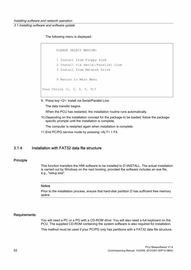
Installing software and network operation 3.1 Installing software and software update
PCU Basesoftware V7.6 52 Commissioning Manual, 10/2006, 6FC5397-0DP10-0BA0
The following menu is displayed:
PLEASE SELECT MEDIUM: 1 Install from Floppy Disk 2 Install via Serial/Parallel Line 3 Install from Network Drive 9 Return to Main Menu Your Choice [1, 2, 3, 5, 9]?
9. Press key <2>: Install via Serial/Parallel Line: The data transfer begins. When the PCU has restarted, the installation routine runs automatically.
10. Depending on the installation concept for the package to be loaded, follow the package-specific prompts until the installation is complete. The computer is restarted again when installation is complete.
11. End PC/PG service mode by pressing <ALT> + F4.
3.1.4 Installation with FAT32 data file structure
Principle This function transfers the HMI software to be installed to D:\INSTALL. The actual installation is carried out by Windows on the next booting, provided the software includes an exe file, e.g., "setup.exe".
Notice Prior to the installation process, ensure that hard-disk partition D has sufficient free memory space.
Requirements You will need a PC or a PG with a CD-ROM drive. You will also need a full keyboard on the PCU. The supplied CD-ROM containing the system software is also required for installation. This method must be used if your PC/PG only has partitions with a FAT32 data file structure.

Installing software and network operation 3.1 Installing software and software update
PCU Basesoftware V7.6 Commissioning Manual, 10/2006, 6FC5397-0DP10-0BA0 53
Transfer The parallel interface for the HMI software installation must be used for the transfer.
Operator action 1. Copy INTERLNK.EXE from the HMI directory on the CD to WINDOWS\COMMAND on
the PC/PG. Insert the following line in CONFIG.SYS: device=c:\windows\command\interlnk.exe /AUTO
2. Switch off the PCU. 3. Using the parallel connecting cable (PC-Link cable, LapLink cable), connect the parallel
port LPT on the PC to port LPT on the PCU. 4. Switch on PCU. 5. Select the "Service menu" in the Boot Manager. [hidden menu entry].
The main menu is displayed: 6. Press key <8>: Start PC Link
The system prompts you to enter a password: 7. Enter one of the passwords for authorization levels 0 - 2. 8. Now copy the entire contents of the HMI Advanced directory on the CD to the
D:\INSTALL directory on the PCU. 9. On completion of the transfer, close INTERSVR on the PCU by pressing <ALT> + F4.
The computer is then restarted. The installation now proceeds automatically with the PCU’s InstallShield. You can operate the InstallShield prompt dialogs with TAB and the cursor keys (TAB corresponds to the END key on the OP0xx).
10. The system boots after the PCU has restarted.
3.1.5 Installation via network connection
Overview This function transfers the HMI software to be installed to D:\INSTALL on the PCU. The actual installation is carried out by Windows on the next booting, provided the software includes an exe file, e.g., "setup.exe".
Note Prior to the installation process, ensure that hard-disk partition D has sufficient free memory space. If you are using a different language version of the Windows system, the terms used in the following setting operations may be different. The sequence of operations as specified below, however, is always the same.
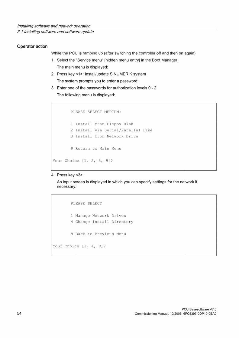
Installing software and network operation 3.1 Installing software and software update
PCU Basesoftware V7.6 54 Commissioning Manual, 10/2006, 6FC5397-0DP10-0BA0
Operator action While the PCU is ramping up (after switching the controller off and then on again) 1. Select the "Service menu" [hidden menu entry] in the Boot Manager.
The main menu is displayed: 2. Press key <1>: Install/update SINUMERIK system
The system prompts you to enter a password: 3. Enter one of the passwords for authorization levels 0 - 2.
The following menu is displayed:
PLEASE SELECT MEDIUM: 1 Install from Floppy Disk 2 Install via Serial/Parallel Line 3 Install from Network Drive 9 Return to Main Menu Your Choice [1, 2, 3, 9]?
4. Press key <3>. An input screen is displayed in which you can specify settings for the network if necessary:
PLEASE SELECT 1 Manage Network Drives 4 Change Install Directory 9 Back to Previous Menu Your Choice [1, 4, 9]?
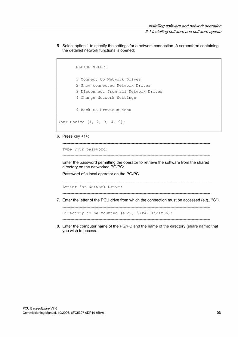
Installing software and network operation 3.1 Installing software and software update
PCU Basesoftware V7.6 Commissioning Manual, 10/2006, 6FC5397-0DP10-0BA0 55
5. Select option 1 to specify the settings for a network connection. A screenform containing the detailed network functions is opened:
PLEASE SELECT 1 Connect to Network Drives 2 Show connected Network Drives 3 Disconnect from all Network Drives 4 Change Network Settings 9 Back to Previous Menu Your Choice [1, 2, 3, 4, 9]?
6. Press key <1>: --------------------------------------------------------------------------------------------------------------- Type your password: --------------------------------------------------------------------------------------------------------------- Enter the password permitting the operator to retrieve the software from the shared directory on the networked PG/PC: Password of a local operator on the PG/PC --------------------------------------------------------------------------------------------------------------- Letter for Network Drive: ---------------------------------------------------------------------------------------------------------------
7. Enter the letter of the PCU drive from which the connection must be accessed (e.g., "G"). --------------------------------------------------------------------------------------------------------------- Directory to be mounted (e.g., \\r4711\dir66): ---------------------------------------------------------------------------------------------------------------
8. Enter the computer name of the PG/PC and the name of the directory (share name) that you wish to access.

Installing software and network operation 3.1 Installing software and software update
PCU Basesoftware V7.6 56 Commissioning Manual, 10/2006, 6FC5397-0DP10-0BA0
The connection data for the PG/PC are displayed:
Machine Name: PCU_1_Name
User Name: auduser Transport Protocol: NETBEUI Logon to domain: No Connect Network Drive (last): G: (\\r3344\HMINEW)
PLEASE SELECT 1 Connect to Network Drives 2 Show connected Network Drives 3 Disconnect from all Network Drives 4 Change Network Settings 9 Back to Previous Menu Your Choice [1, 2, 3, 4, 9]?
9. Press key <9> twice. The following menu is displayed:
PLEASE SELECT 1 Manage Network Drives 4 Change Install Directory 5 Install from G: 9 Back to Previous Menu Your Choice [1, 4, 5, 9]?
Result: The newly activated network connection can be installed with option <5>.
Changing the installation directory on the connected drive If the software to be installed is located in a subdirectory of the shared directory, you can change the installation directory as follows. 1. Press key <4>: Change Install Directory
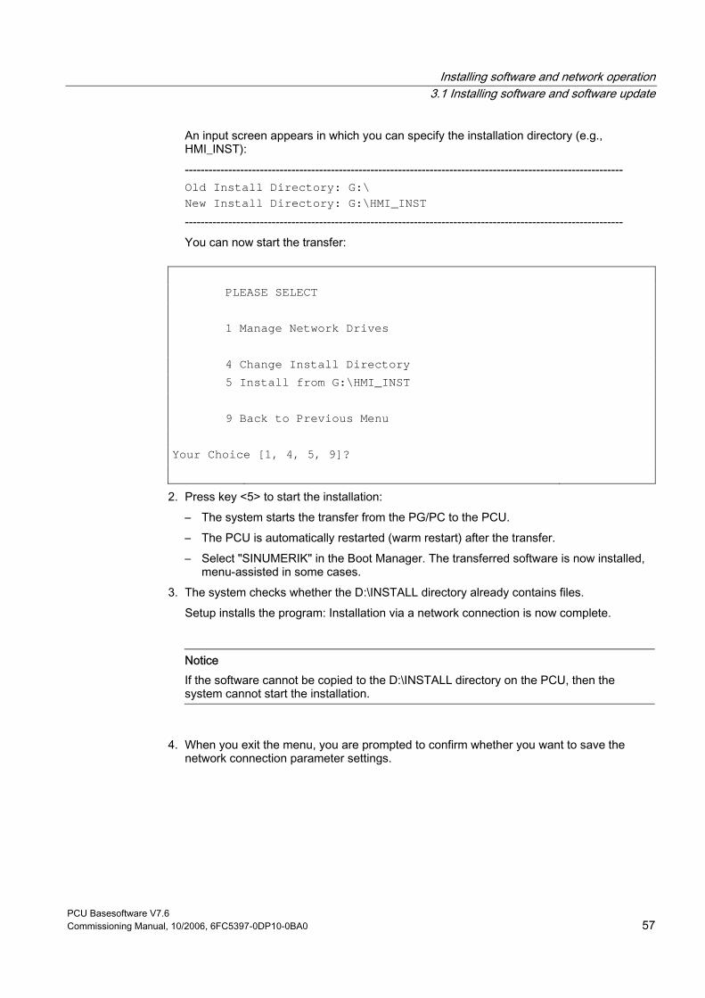
Installing software and network operation 3.1 Installing software and software update
PCU Basesoftware V7.6 Commissioning Manual, 10/2006, 6FC5397-0DP10-0BA0 57
An input screen appears in which you can specify the installation directory (e.g., HMI_INST): --------------------------------------------------------------------------------------------------------------- Old Install Directory: G:\ New Install Directory: G:\HMI_INST --------------------------------------------------------------------------------------------------------------- You can now start the transfer:
PLEASE SELECT 1 Manage Network Drives 4 Change Install Directory 5 Install from G:\HMI_INST 9 Back to Previous Menu Your Choice [1, 4, 5, 9]?
2. Press key <5> to start the installation: – The system starts the transfer from the PG/PC to the PCU. – The PCU is automatically restarted (warm restart) after the transfer. – Select "SINUMERIK" in the Boot Manager. The transferred software is now installed,
menu-assisted in some cases. 3. The system checks whether the D:\INSTALL directory already contains files.
Setup installs the program: Installation via a network connection is now complete.
Notice If the software cannot be copied to the D:\INSTALL directory on the PCU, then the system cannot start the installation.
4. When you exit the menu, you are prompted to confirm whether you want to save the network connection parameter settings.
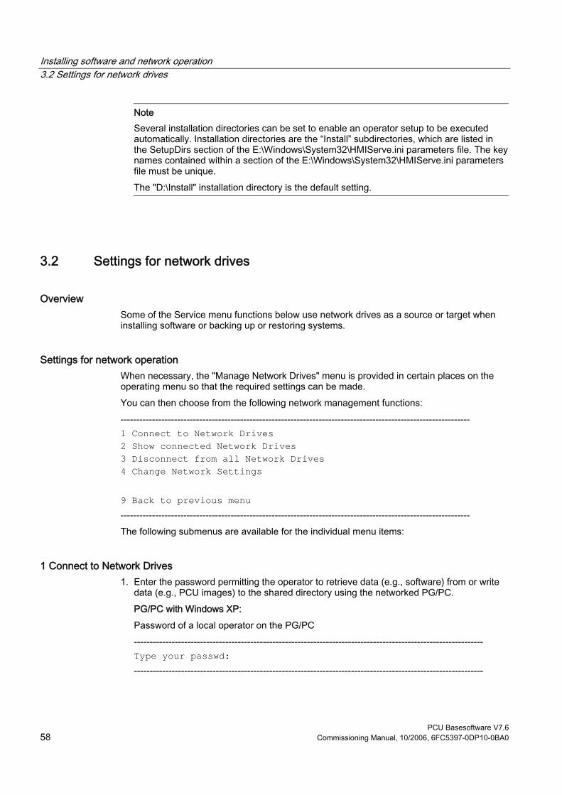
Installing software and network operation 3.2 Settings for network drives
PCU Basesoftware V7.6 58 Commissioning Manual, 10/2006, 6FC5397-0DP10-0BA0
Note Several installation directories can be set to enable an operator setup to be executed automatically. Installation directories are the “Install” subdirectories, which are listed in the SetupDirs section of the E:\Windows\System32\HMIServe.ini parameters file. The key names contained within a section of the E:\Windows\System32\HMIServe.ini parameters file must be unique. The "D:\Install" installation directory is the default setting.
3.2 Settings for network drives
Overview Some of the Service menu functions below use network drives as a source or target when installing software or backing up or restoring systems.
Settings for network operation When necessary, the "Manage Network Drives" menu is provided in certain places on the operating menu so that the required settings can be made. You can then choose from the following network management functions: --------------------------------------------------------------------------------------------------------------- 1 Connect to Network Drives 2 Show connected Network Drives 3 Disconnect from all Network Drives 4 Change Network Settings 9 Back to previous menu --------------------------------------------------------------------------------------------------------------- The following submenus are available for the individual menu items:
1 Connect to Network Drives 1. Enter the password permitting the operator to retrieve data (e.g., software) from or write
data (e.g., PCU images) to the shared directory using the networked PG/PC. PG/PC with Windows XP: Password of a local operator on the PG/PC --------------------------------------------------------------------------------------------------------------- Type your passwd: ---------------------------------------------------------------------------------------------------------------

Installing software and network operation 3.2 Settings for network drives
PCU Basesoftware V7.6 Commissioning Manual, 10/2006, 6FC5397-0DP10-0BA0 59
2. Enter the letter of the PCU drive from which the connection must be accessed (e.g., "G"). --------------------------------------------------------------------------------------------------------------- Letter for Network Drive: ---------------------------------------------------------------------------------------------------------------
3. Enter the computer name of the PG/PC and the name of the directory (share name) that you wish to access. A screenform opens containing data for the PG/PC connection: --------------------------------------------------------------------------------------------------------------- Directory to be mounted (e.g., \\r3344\HMINEW): --------------------------------------------------------------------------------------------------------------- --------------------------------------------------------------------------------------------------------------- Machine Name: PCU_1_Name User Name: auduser Transport Protocol: NETBEUI Logon to domain: No Connect Network Drive (last): G: (\\r3344\HMINEW) PLEASE SELECT 1 Connect to Network Drive 2 Show connected Network Drives 3 Disconnect from all Network Drives 4 Change Network Settings 9 Back to previous Menu Your choice [1, 2, 3, 4, 9]:? ---------------------------------------------------------------------------------------------------------------
2 Show connected Network Drives The current status of the connected drives is displayed: --------------------------------------------------------------------------------------------------------------- Status: OK Local Name: G: Remote Name: \\r3344\HMINEW Status: OK Local Name: H: Remote Name: \\r3344\HMI_P1 Press any key to continue ... ---------------------------------------------------------------------------------------------------------------
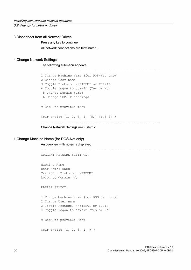
Installing software and network operation 3.2 Settings for network drives
PCU Basesoftware V7.6 60 Commissioning Manual, 10/2006, 6FC5397-0DP10-0BA0
3 Disconnect from all Network Drives Press any key to continue ... All network connections are terminated.
4 Change Network Settings The following submenu appears: --------------------------------------------------------------------------------------------------------------- 1 Change Machine Name (for DOS-Net only) 2 Change User name 3 Toggle Protocol (NETBEUI or TCP/IP) 4 Toggle logon to domain (Yes or No) [5 Change Domain Name] [6 Change TCP/IP settings] 9 Back to previous menu Your choice [1, 2, 3, 4, [5,] [6,] 9] ? --------------------------------------------------------------------------------------------------------------- Change Network Settings menu items:
1 Change Machine Name (for DOS-Net only) An overview with notes is displayed: --------------------------------------------------------------------------------------------------------------- CURRENT NETWORK SETTINGS: Machine Name : User Name: USER Transport Protocol: NETBEUI Logon to domain: No PLEASE SELECT: 1 Change Machine Name (for DOS Net only) 2 Change User name 3 Toggle Protocol (NETBEUI or TCPIP) 4 Toggle logon to domain (Yes or No) 9 Back to previous Menu Your choice [1, 2, 3, 4, 9]?

Installing software and network operation 3.2 Settings for network drives
PCU Basesoftware V7.6 Commissioning Manual, 10/2006, 6FC5397-0DP10-0BA0 61
HINT: This change is temporary for the DOS net only! On the next Windows start, this Machine Name is reset to the Windows Machine Name. If you want to set the Machine Name permanently, please use "Change Machine Name (for Windows and DOS net)" in the upper menu hierarchy! OLD Machine Name: ... NEW Machine Name: ... ---------------------------------------------------------------------------------------------------------------
Note If no new name is entered, the old name is retained.
2 Change User name --------------------------------------------------------------------------------------------------------------- OLD User Name: ... NEW User Name: ... ---------------------------------------------------------------------------------------------------------------
Note If no new name is entered, the old name is retained.
3 Toggle Protocol (NETBEUI or TCP/IP) Each time you press <3> you toggle from the current protocol to the other one. The current protocol setting is displayed in the header for the connection.
Note If a connection has already been established with NETBEUI, you must restart the system to toggle to TCP/IP. If a connection has not yet been established, you can toggle to the other protocol immediately. If a connection has already been established with TCP/IP, you must restart the system to toggle to NETBEUI.
If you have toggled to TCP/IP, the expanded Change Network Settings screenform displays an additional point 6 Change TCP/IP settings, if TCP/IP has been set as the current protocol.

Installing software and network operation 3.2 Settings for network drives
PCU Basesoftware V7.6 62 Commissioning Manual, 10/2006, 6FC5397-0DP10-0BA0
Screenform to toggle from TCPIP → NETBEUI, connection already established: --------------------------------------------------------------------------------------------------------------- CURRENT NETWORK SETTINGS: Machine Name: PCUXXXXXXX User Name: auduser Transport Protocol: TCPIP, get IP Addresses automatically via DHCP Logon to domain: No PLEASE SELECT: 1 Change Machine Name (for DOS Net only) 2 Change User name 3 Toggle Protocol (NETBEUI or TCPIP) 4 Toggle logon to domain (Yes or No) 6 Change TCPIP settings 9 Back to previous Menu Your choice [1, 2, 3, 4, 6, 9]? WARNING: You already had a connection with TCPIP, now you want to toggle the protocol. You can do this (and save the changes), but then you can't connect again without rebooting! Do you really want to toggle the protocol [Y, N]? ---------------------------------------------------------------------------------------------------------------
4 Toggle logon to domain (Yes or No) If Toggle logon to domain is acknowledged with Y, and the domain password is stored in the password list, the system connects to the server immediately and activates the associated login script, if defined. If Toggle logon to domain is acknowledged with N, a dialog box for entering the domain and password appears. The same applies if the domain password is not included in the password list. Domain logon is only activated if Y is set.
5 Change DOMAIN Name This can be used in the same way as the name changes in options 1 and 2. If Toggle logon to domain is acknowledged with N, the additional item 5 Change DOMAIN Name is omitted from menu Change Network Settings.

Installing software and network operation 3.2 Settings for network drives
PCU Basesoftware V7.6 Commissioning Manual, 10/2006, 6FC5397-0DP10-0BA0 63
6 Change TCP/IP settings The following suboptions are offered for the TCP/IP protocol: --------------------------------------------------------------------------------------------------------------- 1 Toggle "Get IP Addresses" (automatically or manually) 2 Change IP Address 3 Change Subnetmask 4 Change Gateway 5 Domain Name Server 6 Change DNS Extension 9 Back to previous menu Your choice [1, 2, 3, 4, 5, 6, 9]? --------------------------------------------------------------------------------------------------------------- Using the suboptions: 1 Toggle "Get IP Addresses" This option toggles between automatically and manually. If “automatically” is set, IP addresses are retrieved via DHCP. A suitable Domain Name Server (DNS) must then be used. If “manually” is set, the IP address is entered directly under 2 Change IP Address.
Note All IP address/subnetmask entries in this screenform must be entered with a blank as separator rather than the usual period. Example 192 168 3 2 instead of 192.168.3.2
2 Change IP Address If "Get IP Addresses" is set to “manually”, the IP address of the PG/PC is entered here. DHCP cannot be selected. 3 Change Subnetmask If "Get IP Addresses" is set to “manually”, the subnetmask of the PG/PC is entered here. DHCP cannot be selected. Notation is the same as for IP address with a blank as a separator. --------------------------------------------------------------------------------------------------------------- Old Subnetmask: ... New Subnetmask: <Subnetmask> --------------------------------------------------------------------------------------------------------------- 4 Change Gateway If "Get IP Addresses" is set to “manually”, the gateway is entered here. The gateway is entered as an IP address.

Installing software and network operation 3.3 Network operation with the Service desktop
PCU Basesoftware V7.6 64 Commissioning Manual, 10/2006, 6FC5397-0DP10-0BA0
--------------------------------------------------------------------------------------------------------------- Old Gateway: ... New Gateway: <IP address> --------------------------------------------------------------------------------------------------------------- 5 Domain Name Server If "Get IP Addresses" is set to “automatically” via DHCP, the IP address of the Domain Name Server (DNS) is entered here. DHCP normally has a suitable Domain Name Server. If the DNS has access to the correct computer/IP address assignment, nothing has to be entered here. 6 Change DNS Extension The extension of the Domain Name Server is entered here, e.g. SIEMENS.COM
Exiting the menu When you exit the menu, you are prompted to confirm whether you want to save the network connection parameter settings.
3.3 Network operation with the Service desktop
Overview The Service desktop also functions as a service mode that can use the Windows functionality to commission the controller. It also functions as a platform for network operation (e.g., for installing HMI system software), for setting the runtime environment for the HMI system software or for measures relating to the system, such as authorizing SIMATIC STEP 7, checking the hard disk, checking the version, etc.
Configuring network operation The PCU has one network port as standard: 1. Connect the Ethernet cable for TCP/IP communication.
The default setting is DHCP. (Both the TCP/IP and NETBEUI protocols are preinstalled.) 2. You can adjust the settings by selecting Start → Settings → Network Connections → Local
Area Connection → Properties. 3. If it is not already the case, the PCU computer name now has to be made unique in the
network: Select Start → Settings → Control Panel → System, Computer Name tab, "Change" command button to enter the desired name.
Connection via TCP/IP A WINS server can be configured using TCP/IP. The DNS server and DNS extension are omitted. The WINS and gateway entries are also configurable with DHCP, and are displayed. IP addresses can now also be entered with “.” as a separator.

Installing software and network operation 3.3 Network operation with the Service desktop
PCU Basesoftware V7.6 Commissioning Manual, 10/2006, 6FC5397-0DP10-0BA0 65
Note WINS cannot be preassigned with “0 0 0 0”, or the connection to subnets via DHCP will not work.
Post-installing Windows components Requirement: You will need the Windows XP Recovery CD and Service Pack 2 to post-install individual components. Software, which may be required for post-installation if third-party applications have been installed, is also stored at D:\Updates\Base. 1. \MDAC21.SP2: Data Access Components V2.1 SP2 (Y2K-compatible) 2. \SP6a: Windows NT 4.0 Service Pack 6a 3. \DRIVERS\SYSTEM.INI : Keyboard table (must be copied to E:\Windows if required). 4. \DDEFIX
The installation path to be entered for "Install New Fix" is: D:\Updates\Base\DDEFIX\hotfix.inf
5. \VBFIX : Visual Basic Hot fix
3.3.1 Installing and authorizing SIMATIC STEP 7
Overview SIMATIC STEP 7 V5.3 SP2 can also be installed on the PCU.
Delivery item: SIMATIC STEP 7 V5.3 SP2 Components: SIMATIC STEP 7 V5.3 SP2 and
Add-on for SINUMERIK 810D/840D/840D sl/840Di sl Type of delivery: 2 installation CDs System requirements: PCU basic software V8.0 or higher
A network connection or a connection to a CD-ROM drive is required. Recommendation: Mouse port
Note The “MPI driver” package available on the PCU is part of the HMI software and must not be uninstalled!

Installing software and network operation 3.3 Network operation with the Service desktop
PCU Basesoftware V7.6 66 Commissioning Manual, 10/2006, 6FC5397-0DP10-0BA0
Installation under Windows XP You must follow the installation sequence described here! 1. Booting up the PCU in the service desktop. 2. Access CD 1 (via network or external CD-ROM drive) call up SETUP.EXE in the root
directory there. 3. The installation proceeds with operator prompting. The installation directory for STEP 7
should be changed to F:\... where directory in F: can be freely selected. 4. The prompt for "Transfer license keys" must be answered with "No, transfer the license
keys later." The licensing is done after the installation of SINUMERIK AddOn. Once installation is complete, the PC will need to be rebooted. During boot up, select the service desktop again.
5. Switch to the SINUMERIK_Add_on directory on CD 2 and call up SETUP.EXE there. The installation proceeds with operator prompting. Once installation is complete, the PC will need to be rebooted. During boot up, select the service desktop again.
6. Start the link "STEP7 authorizing" on the service desktop. This authorizes STEP 7 and starting can now be done from the HMI Advanced operator interface (STEP 7 appears as its own operating area on the expansion bar of the area menu, protected with protection level 3). The following entries are made automatically in F:\Add_on\oemframe.ini: [s7tgtopx] ; with HMI Advanced: eliminate minimize/maximize buttons ; of the Step7 window WindowStyle_Off=196608 ; with HMI Advanced: switch to previous task when Step7 is terminated nSwitchToTaskAfterTermination= -2 These entries may also need to be modified in OEM configurations.
3.3.2 Authorizing SIMATIC STEP 7 via the Service menu
Requirements The SIMATIC STEP 7 V5.3 SP2 software for SINUMERIK hardware is already installed.
Operator action While the PCU is ramping up (after switching the controller off and then on again): 1. Select the Service menu [hidden menu entry] in the Boot Manager
The main menu is displayed. 2. Press key <2>: SINUMERIK tools and options
The system prompts you to enter a password: 3. Enter a password for authorization levels 0 - 2.

Installing software and network operation 3.3 Network operation with the Service desktop
PCU Basesoftware V7.6 Commissioning Manual, 10/2006, 6FC5397-0DP10-0BA0 67
The following menu is displayed:
PLEASE SELECT X 1 Activate Step7 for PCU 9 Return to Main Menu Your Choice [1, 9]?
4. To authorize STEP 7, press key <1>. The system will then restart automatically. STEP 7 will be authorized when Windows nexts boots before the HMI system software is started.

Installing software and network operation 3.3 Network operation with the Service desktop
PCU Basesoftware V7.6 68 Commissioning Manual, 10/2006, 6FC5397-0DP10-0BA0
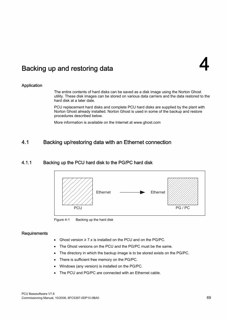
PCU Basesoftware V7.6 Commissioning Manual, 10/2006, 6FC5397-0DP10-0BA0 69
Backing up and restoring data 4Application
The entire contents of hard disks can be saved as a disk image using the Norton Ghost utility. These disk images can be stored on various data carriers and the data restored to the hard disk at a later date. PCU replacement hard disks and complete PCU hard disks are supplied by the plant with Norton Ghost already installed. Norton Ghost is used in some of the backup and restore procedures described below. More information is available on the Internet at www.ghost.com
4.1 Backing up/restoring data with an Ethernet connection
4.1.1 Backing up the PCU hard disk to the PG/PC hard disk
Figure 4-1 Backing up the hard disk
Requirements • Ghost version ≥ 7.x is installed on the PCU and on the PG/PC. • The Ghost versions on the PCU and the PG/PC must be the same. • The directory in which the backup image is to be stored exists on the PG/PC. • There is sufficient free memory on the PG/PC. • Windows (any version) is installed on the PG/PC. • The PCU and PG/PC are connected with an Ethernet cable.
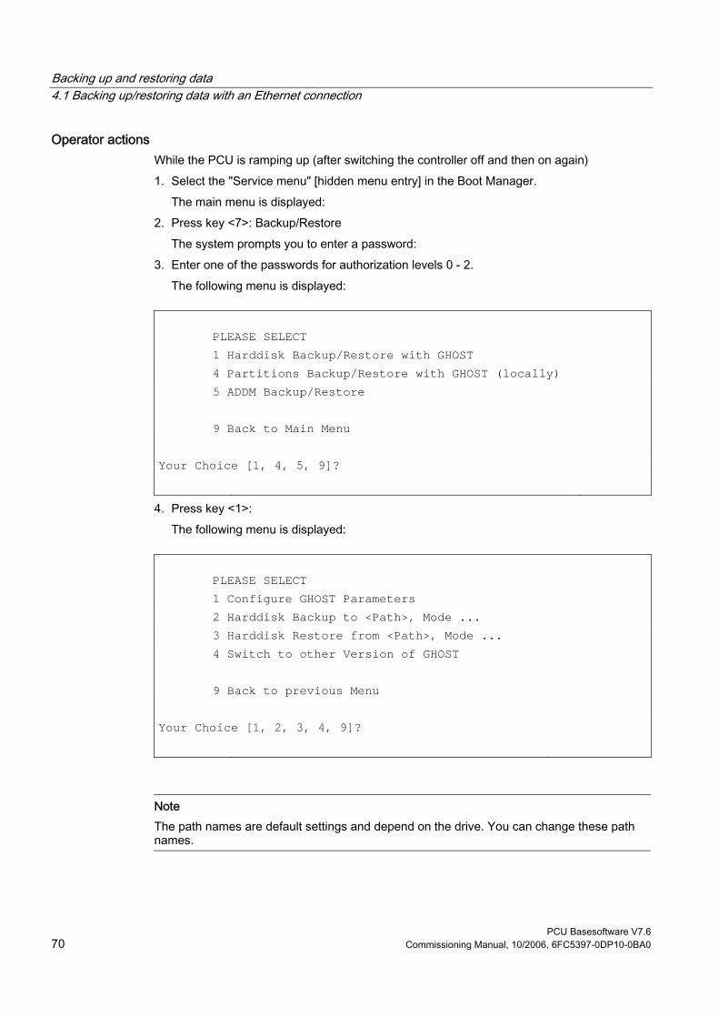
Backing up and restoring data 4.1 Backing up/restoring data with an Ethernet connection
PCU Basesoftware V7.6 70 Commissioning Manual, 10/2006, 6FC5397-0DP10-0BA0
Operator actions While the PCU is ramping up (after switching the controller off and then on again) 1. Select the "Service menu" [hidden menu entry] in the Boot Manager.
The main menu is displayed: 2. Press key <7>: Backup/Restore
The system prompts you to enter a password: 3. Enter one of the passwords for authorization levels 0 - 2.
The following menu is displayed:
PLEASE SELECT 1 Harddisk Backup/Restore with GHOST 4 Partitions Backup/Restore with GHOST (locally) 5 ADDM Backup/Restore 9 Back to Main Menu Your Choice [1, 4, 5, 9]?
4. Press key <1>: The following menu is displayed:
PLEASE SELECT 1 Configure GHOST Parameters 2 Harddisk Backup to <Path>, Mode ... 3 Harddisk Restore from <Path>, Mode ... 4 Switch to other Version of GHOST 9 Back to previous Menu Your Choice [1, 2, 3, 4, 9]?
Note The path names are default settings and depend on the drive. You can change these path names.

Backing up and restoring data 4.1 Backing up/restoring data with an Ethernet connection
PCU Basesoftware V7.6 Commissioning Manual, 10/2006, 6FC5397-0DP10-0BA0 71
"Optional" start The following steps are only applicable if you wish to change the default settings. Here you can set the interface type, the network connection, the backup image path, and the backup image split mode. 1. Set parameters for the Norton Ghost program:
Press key <1>: Configure GHOST Parameters The following menu is displayed:
PLEASE SELECT 1 Set Connection Mode PARALLEL (LPT:) 2 Set Connection Mode LOCAL/NETWORK 3 Change Backup Image Filename 4 Change Restore Image Filename 5 Change Machine Name (for Windows and DOS net) 6 Manage Network Drives 7 Change Split Mode 9 Back to previous Menu Your Choice [1, 2, 3, 4, 5, 6, 7, 9]?
Notice For the network connection described here the interface type must always be set to LOCAL/NETWORK.
1. Change interface: Press key <2>: Set Connection Mode LOCAL/NETWORK and confirm.
2. Establish/change network connection: Press key <6>: Manage Network Drives
3. Change the backup image path: Press key <3>: Change Backup Image Filename: Enter the complete path for the backup file on the PG/PC, e.g. C:\SINUBACK\PCU\HMI.gho

Backing up and restoring data 4.1 Backing up/restoring data with an Ethernet connection
PCU Basesoftware V7.6 72 Commissioning Manual, 10/2006, 6FC5397-0DP10-0BA0
4. Backup image split mode: Press key <7>: Change Split Mode Choose whether you wish to split the backup image into portions and, if so, enter the split size (max. split size: 2048 MB; default split size: 640 MB). The names of the split files are assigned as follows: <name>.gho <name>.001 <name>.002 <name>. ...
5. Return to the previous menu: Press key <9>: Back to previous Menu Prompt: Save GHOST parameters? Answer Yes.
"Optional" end The following steps are always applicable:
Backing up the hard disk You can now start the transfer: 1. Press key <2>: Harddisk Backup to <path name>, Mode LOCAL/NETWORK
The following menu appears if local partition data are available:
PLEASE SELECT 1 Backup WITHOUT Local Images 2 Backup WITH Local Images Your Choice [1, 2]?
If you do NOT want to back up local partition data (substantial reduction in transfer time and memory), select: 1. Press key <1>: Backup WITHOUT Local Images or 2. Press key <2>: Backup WITH Local Images.
– A message window then opens: You are prompted to check whether a connection exists between the PCU and the PG/PC. The target path for the directory on the PG/PC in which the backup image is to be stored is displayed. You are prompted to check whether this directory exists on the PG/PC.

Backing up and restoring data 4.1 Backing up/restoring data with an Ethernet connection
PCU Basesoftware V7.6 Commissioning Manual, 10/2006, 6FC5397-0DP10-0BA0 73
– Type "Y" in the message window to acknowledge and start the backup on the PCU. The Norton Ghost message window appears with: Display of the transfer progress, the paths used and details of the data volumes to be transferred.
– If the backup is cancelled, a query appears: Do you want to try to backup again [Y, N]? Press N to return to the main menu. Press "Y" to restart the backup from scratch.
3. Press key <9>: Return to the previous menu 4. Disconnecting connected network drives: You can terminate all connections to the
PG/PC.
4.1.2 Restoring the PCU hard disk from the PG/PC hard disk
Figure 4-2 Restoring hard-disk content
Requirements • Ghost version ≥ 7.x is installed on the PCU and on the PG/PC. • The directory in which the restore image is stored exists on the PG/PC. • Windows (any version) is installed on the PG/PC. • The PCU and PG/PC are connected with an Ethernet cable.
Operator actions 1. Switch on the PG/PC and insert the CD into the drive.
While the PCU is ramping up (after switching the controller off and then on again) 2. Select the "Service menu" [hidden menu entry] in the Boot Manager.
The main menu is displayed: 3. Press key <7>: Backup/Restore
The system prompts you to enter a password: 4. Enter one of the passwords for authorization levels 0 - 2.

Backing up and restoring data 4.1 Backing up/restoring data with an Ethernet connection
PCU Basesoftware V7.6 74 Commissioning Manual, 10/2006, 6FC5397-0DP10-0BA0
The following menu is displayed:
PLEASE SELECT: 1 Harddisk Backup/Restore with GHOST 4 Partitions Backup/Restore with GHOST (locally) 5 ADDM Backup/Restore 9 Back to Main Menu Your Choice [1, 4, 5, 9]?
1. Select option 1. The following menu is displayed:
PLEASE SELECT: 1 Configure GHOST Parameters 2 Harddisk Backup to <Path>, Mode ... 3 Harddisk Restore from <Path>, Mode ... 4 Switch to other Version of GHOST 9 Back to previous Menu Your Choice [1, 2, 3, 4, 9]?
Note The path names are default settings and depend on the drive. You can change these path names.
"Optional" start The following steps are only applicable if you wish to change the default settings. Here you can set the interface type, the network connection, the backup image path, and the backup image split mode. 1. Set parameters for the Norton Ghost program:
Press key <1>: Configure GHOST Parameters

Backing up and restoring data 4.1 Backing up/restoring data with an Ethernet connection
PCU Basesoftware V7.6 Commissioning Manual, 10/2006, 6FC5397-0DP10-0BA0 75
The following menu is displayed:
PLEASE SELECT: 1 Set Connection Mode PARALLEL (LPT:) 2 Set Connection Mode LOCAL/NETWORK 3 Change Backup Image Filename 4 Change Restore Image Filename 5 Change Machine Name (for Windows and DOS net) 6 Manage Network Drives 7 Change Split Mode 9 Back to previous Menu Your Choice [1, 2, 3, 4, 5, 6, 7, 9]?
Notice For the network connection described here the interface type must always be set to LOCAL/NETWORK.
1. Change interface: Press key <2>: Set Connection Mode LOCAL/NETWORK and confirm.
2. Establish/change network connection: Press key <6>: Manage Network Drives
3. Setting the restore image: Press key <4>: Change Restore Image Filename Enter the complete path for the restore file HMI.gho on the PG/PC, e.g. C:\SINUBACK\PCU\HMI.gho
4. Return to the previous menu: Press key <9>: Back to previous Menu Prompt: Save GHOST parameters? Answer Yes.
"Optional" end The following steps are always applicable:

Backing up and restoring data 4.1 Backing up/restoring data with an Ethernet connection
PCU Basesoftware V7.6 76 Commissioning Manual, 10/2006, 6FC5397-0DP10-0BA0
Restore contents of hard disk 1. Press key <3>: Harddisk Restore from <path name>, Mode LOCAL
Selecting this option opens the following menu:
For partitioning the disk it's important to know the SYSTEM BASE of the imaged configuration. Please select the SYSTEM BASE the image was created by!
PLEASE SELECT 1 Windows XP 2 Windows NT 3 Win95 4 WfW3.11 5 DOS (spare part) 9 Back to previous Menu Your Choice [1, 2, 3, 4, 5, 9]?
2. Select the operating system on which the restore image is based. This affects the type of hard disk partitioning that is performed. When you select the appropriate operating system, another menu opens:
What kind of disk partitioning do you want? 1 Standard Partitioning (default) 2 User-defined Partitioning 3 Image Partitioning Your Choice [1, 2, 3]?
3. Specify whether you want standard hard disk partitioning, i.e., with a fixed number and size of partitions (depending on the operating system), or whether you want to define the partitioning yourself. In the first case, Norton Ghost sets the partition parameters automatically, whereas in the second case the operator sets the partition parameters in Norton Ghost. In the third case, the image to be loaded determines the partitioning.
4. Press key < 9 >: Return to the previous menu 5. On first commissioning or restore only (selected automatically with Ghost or Restore):
Select "1 Configure GHOST Parameters" in the menu

Backing up and restoring data 4.1 Backing up/restoring data with an Ethernet connection
PCU Basesoftware V7.6 Commissioning Manual, 10/2006, 6FC5397-0DP10-0BA0 77
Set the PCU network name
If your machine is part of a NETWORK, it needs a machine name that is unique in the overall network. The restore image brings along a machine name. You can change this machine name now. CAUTION: The machine name shouldn't be changed, if: 1. the restore image is a backup image of your machine AND 2. the name of your machine hasn't been changed since creating the backup image. NOTE for networks that require Microsoft Domain security: Whenever you change the machine name (even if you input a name identical to the machine name contained in the restore image), your machine and its users will NO LONGER belong to the Microsoft network domain (see also the Microsoft documentation). Press any key to continue . . .
Do you REALLY want to input a new machine name? If you want to input the new machine name MANUALLY, 1. don't use "/\[]:;|<>+=,?*" and blanks AND 2. the new machine name has to be EXACTLY as long as the old machine name used within the restore image. If you don't want to input a new machine name, the machine name used within the restore image remains valid.
HINT: if you want to input a machine name with a different length, you have to do this in Windows!
PLEASE SELECT: 1 Input Machine Name MANUALLY 2 Input Machine Name RANDOMLY 9 No new Machine Name Your Choice [1, 2, 9]?
You can choose to enter a computer name for the PCU yourself or have a name generated automatically: • Enter name yourself:
<1 Input Machine Name MANUALLY >

Backing up and restoring data 4.1 Backing up/restoring data with an Ethernet connection
PCU Basesoftware V7.6 78 Commissioning Manual, 10/2006, 6FC5397-0DP10-0BA0
An input screen is displayed in which you enter the new 10-character name. On pressing Enter to confirm, the name is changed in the system. Default name: PCUxxxxxxx [10 characters].
• Enter name automatically: < 2 Input Machine Name RANDOMLY > A computer name is generated automatically and transferred to the system. If necessary, you can view the name on the Windows Control Panel: "Start" → "Settings" → "Control Panel" → "System", "Computer Name" tab
• The Norton Ghost message window appears on the PCU: – display of the transfer progress – display of the paths used – Details of the data to be transferred
If standard commissioning is to be performed from a GHOST image, the current PCU name must be set instead of the name contained in the GHOST image. The new computer name (including the name generated with "2 Input Machine Name RANDOMLY") and the new system ID (SID) are assigned to the PCU with the Ghostwalker utility. On completion of the Ghostwalker sequence, the operator is given the opportunity to repeat the restore process. This function is needed if the restore process has not been carried out correctly (e.g., connection problems, canceled by the operator, etc.). If there is no operator access within 5 seconds, the PCU is restarted automatically. The computer name can be changed in Windows if required.
It seems, that Ghost Restore succeeded. But if there was no connection or a cancel of the Restore, Ghost reports NO Errors! So you have the chance to:
PLEASE SELECT: 1 Reboot the System (default after 5 Seconds) 2 Try the Harddisk Restore again 9 Back to previous Menu Your Choice [1, 2, 9]?
You can change the computer name again at a later stage by selecting option 5 "Change Machine Name (for Windows and DOS net)" in submenu Backup/Restore → Harddisk Backup/Restore with GHOST → Configure GHOST Parameters. This change is also made via Ghostwalker. Boot: The system must be booted following a successful restore process.
Backing up and restoring data 4.1 Backing up/restoring data with an Ethernet connection
PCU Basesoftware V7.6 Commissioning Manual, 10/2006, 6FC5397-0DP10-0BA0 79
Notice If the restore process was interrupted, the system on the hard disk will be incomplete. In this situation, a boot diskette with Norton Ghost and the network software is required. The boot diskette is available from eSupport.
4.1.3 Commissioning a replacement hard disk The mechanical and electrical steps involved in replacing a hard disk are described in: References:Operator Components Manual The process for restoring the data backup of an entire hard disk, in order to always have operator and system data available for service purposes, is described below.
Norton Ghost The entire contents of hard disks can be saved as a disk image file using the Norton Ghost utility. This disk image file can be stored on various data carriers and the data restored to the hard disk at a later date. PCUs and replacement hard disks are supplied by the plant with Norton Ghost already installed. Recommendation: Archive the hard disk backup (hard disk image), including the "Norton Ghost" utility, on CD.
Restoring data backup Requirements: • Ghost is installed on the PG. • A new replacement hard disk has been obtained. • The PCU is connected to the PC/PG with a parallel cable. • The PG has a CD drive.
Note The replacement hard disk does not contain a Windows operating system or HMI system software.

Backing up and restoring data 4.1 Backing up/restoring data with an Ethernet connection
PCU Basesoftware V7.6 80 Commissioning Manual, 10/2006, 6FC5397-0DP10-0BA0
Operations: 1. Install the replacement hard disk in the PCU (installation guide is supplied with new hard
disk): – Insert the hard disk into the hinges. – Insert the connecting cable between hard disk and PCU. – Secure the hard disk with the 4 knurled-head screws. – Remove the transport lock: Turn towards "operating" until it engages.
2. Switch on the PG and insert the CD in the drive. While the PCU is ramping up (after switching the controller off and then on again)
3. Select the "Service menu" [hidden menu entry] in the Boot Manager. The main menu is displayed:
4. Press key <7>: Backup/Restore The system prompts you to enter a password:
5. Enter one of the passwords for authorization levels 0 - 2. The following menu is displayed:
PLEASE SELECT 1 Harddisk Backup/Restore with GHOST 4 Partitions Backup/Restore with GHOST (locally) 5 ADDM Backup/Restore 9 Back to Main Menu Your Choice [1, 4, 5, 9]?
6. Press key <1> Set parameters for Norton Ghost:
7. Press key <1>: Configure GHOST parameters 8. Press key <3>: Harddisk Restore from <path name>, Mode PARALLEL
When this menu is chosen, a message box appears: You are prompted to check whether a connection exists between the HMI and the PG/PC. Select the HMI image file to be loaded as the restore image. – PG/PC:
In a DOS window or at the DOS level enter the command "ghost -lps" to start Norton Ghost.
– PCU: Start the restore process by acknowledging the message window (Yes).
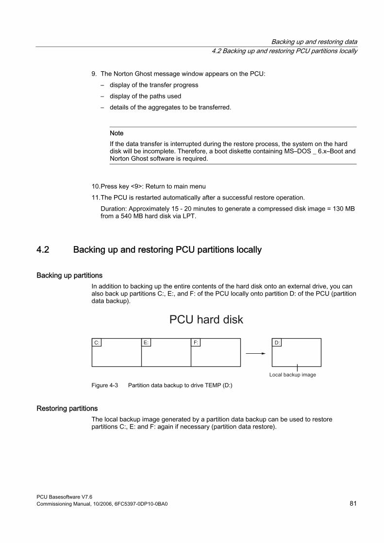
Backing up and restoring data 4.2 Backing up and restoring PCU partitions locally
PCU Basesoftware V7.6 Commissioning Manual, 10/2006, 6FC5397-0DP10-0BA0 81
9. The Norton Ghost message window appears on the PCU: – display of the transfer progress – display of the paths used – details of the aggregates to be transferred.
Note If the data transfer is interrupted during the restore process, the system on the hard disk will be incomplete. Therefore, a boot diskette containing MS–DOS _ 6.x–Boot and Norton Ghost software is required.
10. Press key <9>: Return to main menu 11. The PCU is restarted automatically after a successful restore operation.
Duration: Approximately 15 - 20 minutes to generate a compressed disk image = 130 MB from a 540 MB hard disk via LPT.
4.2 Backing up and restoring PCU partitions locally
Backing up partitions In addition to backing up the entire contents of the hard disk onto an external drive, you can also back up partitions C:, E:, and F: of the PCU locally onto partition D: of the PCU (partition data backup).
Figure 4-3 Partition data backup to drive TEMP (D:)
Restoring partitions The local backup image generated by a partition data backup can be used to restore partitions C:, E: and F: again if necessary (partition data restore).
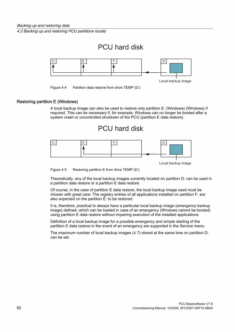
Backing up and restoring data 4.2 Backing up and restoring PCU partitions locally
PCU Basesoftware V7.6 82 Commissioning Manual, 10/2006, 6FC5397-0DP10-0BA0
Figure 4-4 Partition data restore from drive TEMP (D:)
Restoring partition E (Windows) A local backup image can also be used to restore only partition E: (Windows) (Windows) if required. This can be necessary if, for example, Windows can no longer be booted after a system crash or uncontrolled shutdown of the PCU (partition E data restore).
Figure 4-5 Restoring partition E from drive TEMP (D:)
Theoretically, any of the local backup images currently located on partition D: can be used in a partition data restore or a partition E data restore. Of course, in the case of partition E data restore, the local backup image used must be chosen with great care: The registry entries of all applications installed on partition F: are also expected on the partition E: to be restored. It is, therefore, practical to always have a particular local backup image (emergency backup image) defined, which can be loaded in case of an emergency (Windows cannot be booted) using partition E data restore without impairing execution of the installed applications. Definition of a local backup image for a possible emergency and simple starting of the partition E data restore in the event of an emergency are supported in the Service menu. The maximum number of local backup images (≤ 7) stored at the same time on partition D: can be set.
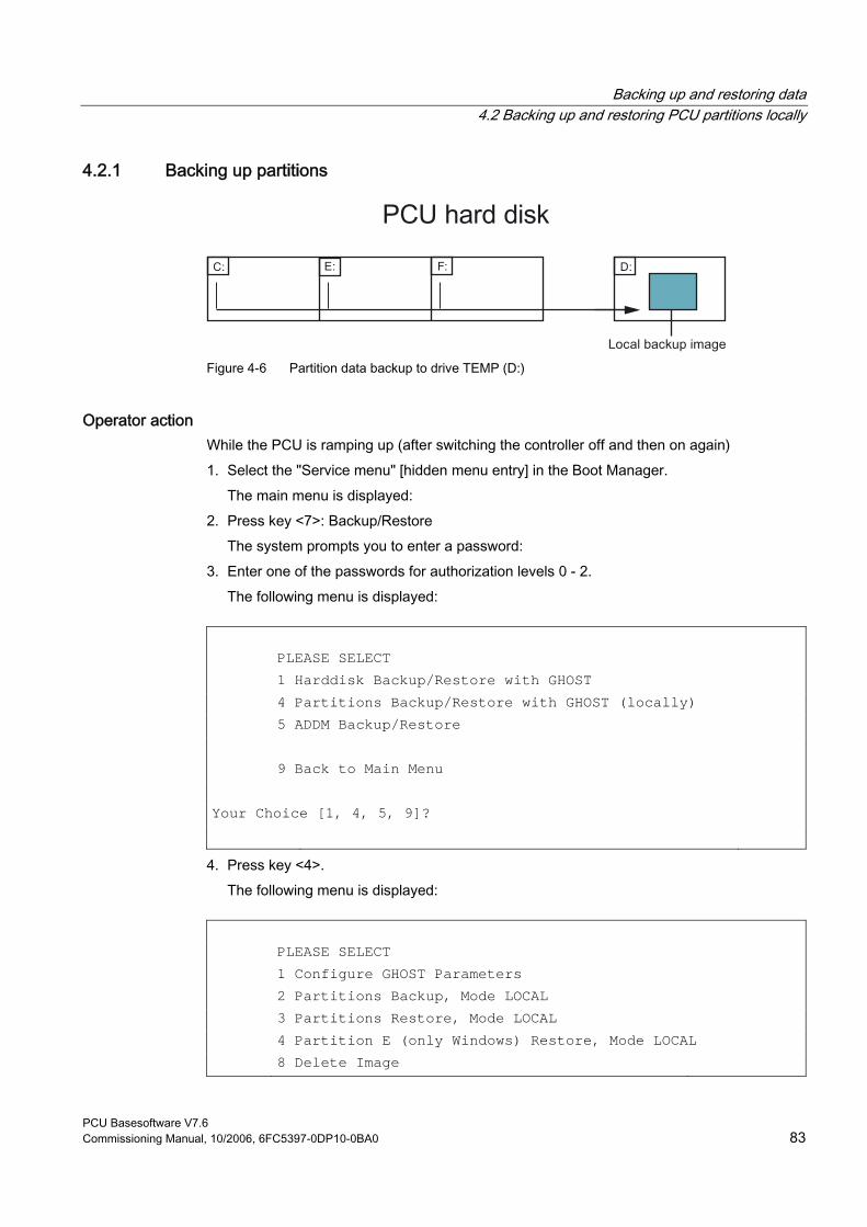
Backing up and restoring data 4.2 Backing up and restoring PCU partitions locally
PCU Basesoftware V7.6 Commissioning Manual, 10/2006, 6FC5397-0DP10-0BA0 83
4.2.1 Backing up partitions
Figure 4-6 Partition data backup to drive TEMP (D:)
Operator action While the PCU is ramping up (after switching the controller off and then on again) 1. Select the "Service menu" [hidden menu entry] in the Boot Manager.
The main menu is displayed: 2. Press key <7>: Backup/Restore
The system prompts you to enter a password: 3. Enter one of the passwords for authorization levels 0 - 2.
The following menu is displayed:
PLEASE SELECT 1 Harddisk Backup/Restore with GHOST 4 Partitions Backup/Restore with GHOST (locally) 5 ADDM Backup/Restore 9 Back to Main Menu Your Choice [1, 4, 5, 9]?
4. Press key <4>. The following menu is displayed:
PLEASE SELECT 1 Configure GHOST Parameters 2 Partitions Backup, Mode LOCAL 3 Partitions Restore, Mode LOCAL 4 Partition E (only Windows) Restore, Mode LOCAL 8 Delete Image
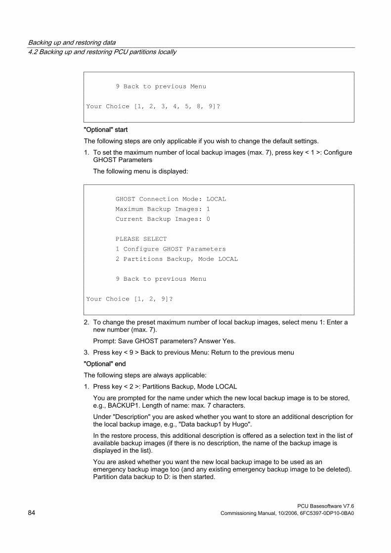
Backing up and restoring data 4.2 Backing up and restoring PCU partitions locally
PCU Basesoftware V7.6 84 Commissioning Manual, 10/2006, 6FC5397-0DP10-0BA0
9 Back to previous Menu Your Choice [1, 2, 3, 4, 5, 8, 9]?
"Optional" start The following steps are only applicable if you wish to change the default settings. 1. To set the maximum number of local backup images (max. 7), press key < 1 >: Configure
GHOST Parameters The following menu is displayed:
GHOST Connection Mode: LOCAL Maximum Backup Images: 1 Current Backup Images: 0 PLEASE SELECT 1 Configure GHOST Parameters 2 Partitions Backup, Mode LOCAL 9 Back to previous Menu Your Choice [1, 2, 9]?
2. To change the preset maximum number of local backup images, select menu 1: Enter a new number (max. 7). Prompt: Save GHOST parameters? Answer Yes.
3. Press key < 9 > Back to previous Menu: Return to the previous menu "Optional" end The following steps are always applicable: 1. Press key < 2 >: Partitions Backup, Mode LOCAL
You are prompted for the name under which the new local backup image is to be stored, e.g., BACKUP1. Length of name: max. 7 characters. Under "Description" you are asked whether you want to store an additional description for the local backup image, e.g., "Data backup1 by Hugo". In the restore process, this additional description is offered as a selection text in the list of available backup images (if there is no description, the name of the backup image is displayed in the list). You are asked whether you want the new local backup image to be used as an emergency backup image too (and any existing emergency backup image to be deleted). Partition data backup to D: is then started.
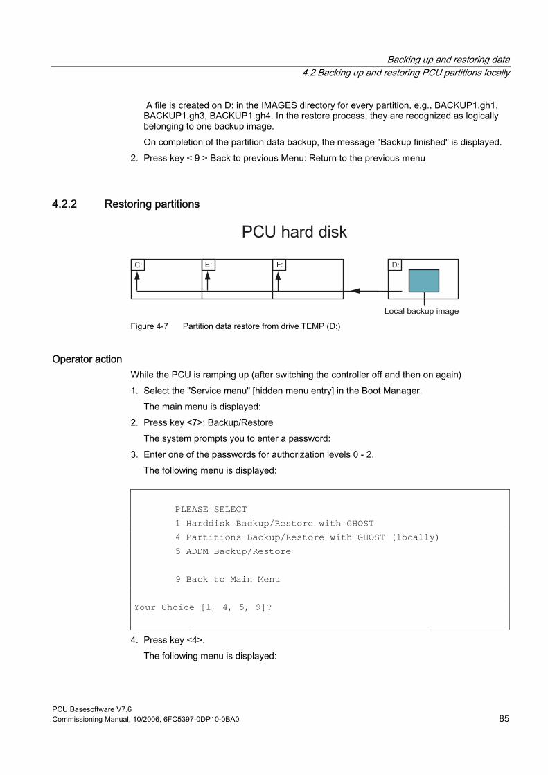
Backing up and restoring data 4.2 Backing up and restoring PCU partitions locally
PCU Basesoftware V7.6 Commissioning Manual, 10/2006, 6FC5397-0DP10-0BA0 85
A file is created on D: in the IMAGES directory for every partition, e.g., BACKUP1.gh1, BACKUP1.gh3, BACKUP1.gh4. In the restore process, they are recognized as logically belonging to one backup image. On completion of the partition data backup, the message "Backup finished" is displayed.
2. Press key < 9 > Back to previous Menu: Return to the previous menu
4.2.2 Restoring partitions
Figure 4-7 Partition data restore from drive TEMP (D:)
Operator action While the PCU is ramping up (after switching the controller off and then on again) 1. Select the "Service menu" [hidden menu entry] in the Boot Manager.
The main menu is displayed: 2. Press key <7>: Backup/Restore
The system prompts you to enter a password: 3. Enter one of the passwords for authorization levels 0 - 2.
The following menu is displayed:
PLEASE SELECT 1 Harddisk Backup/Restore with GHOST 4 Partitions Backup/Restore with GHOST (locally) 5 ADDM Backup/Restore 9 Back to Main Menu Your Choice [1, 4, 5, 9]?
4. Press key <4>. The following menu is displayed:
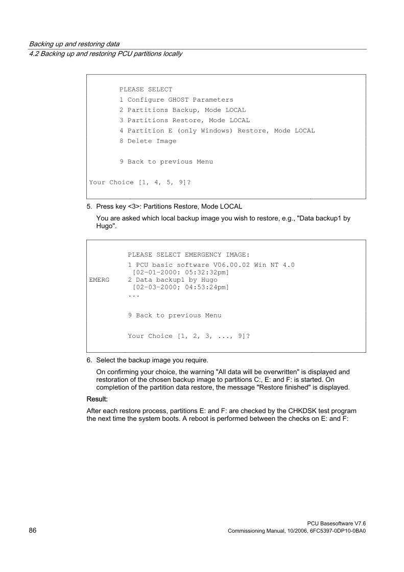
Backing up and restoring data 4.2 Backing up and restoring PCU partitions locally
PCU Basesoftware V7.6 86 Commissioning Manual, 10/2006, 6FC5397-0DP10-0BA0
PLEASE SELECT 1 Configure GHOST Parameters 2 Partitions Backup, Mode LOCAL 3 Partitions Restore, Mode LOCAL 4 Partition E (only Windows) Restore, Mode LOCAL 8 Delete Image 9 Back to previous Menu Your Choice [1, 4, 5, 9]?
5. Press key <3>: Partitions Restore, Mode LOCAL You are asked which local backup image you wish to restore, e.g., "Data backup1 by Hugo".
PLEASE SELECT EMERGENCY IMAGE: 1 PCU basic software V06.00.02 Win NT 4.0
[02-01-2000: 05:32:32pm]
EMERG 2 Data backup1 by Hugo [02-03-2000; 04:53:24pm]
... 9 Back to previous Menu Your Choice [1, 2, 3, ..., 9]?
6. Select the backup image you require. On confirming your choice, the warning "All data will be overwritten" is displayed and restoration of the chosen backup image to partitions C:, E: and F: is started. On completion of the partition data restore, the message "Restore finished" is displayed.
Result: After each restore process, partitions E: and F: are checked by the CHKDSK test program the next time the system boots. A reboot is performed between the checks on E: and F:
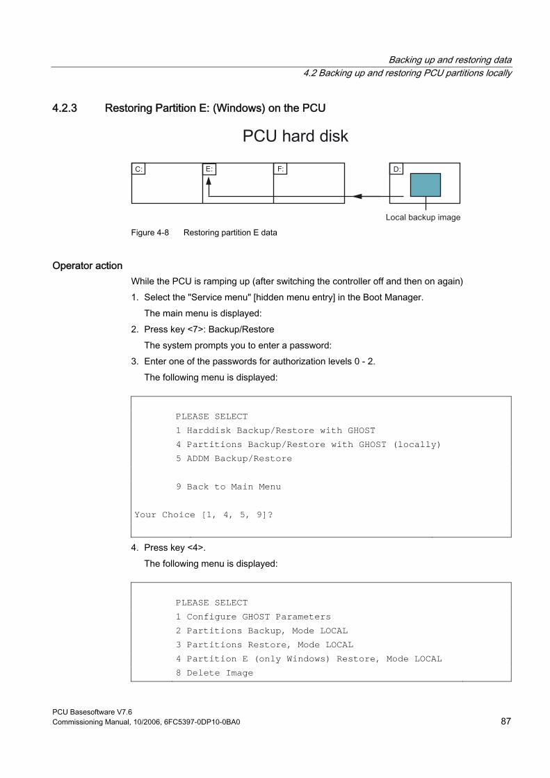
Backing up and restoring data 4.2 Backing up and restoring PCU partitions locally
PCU Basesoftware V7.6 Commissioning Manual, 10/2006, 6FC5397-0DP10-0BA0 87
4.2.3 Restoring Partition E: (Windows) on the PCU
Figure 4-8 Restoring partition E data
Operator action While the PCU is ramping up (after switching the controller off and then on again) 1. Select the "Service menu" [hidden menu entry] in the Boot Manager.
The main menu is displayed: 2. Press key <7>: Backup/Restore
The system prompts you to enter a password: 3. Enter one of the passwords for authorization levels 0 - 2.
The following menu is displayed:
PLEASE SELECT 1 Harddisk Backup/Restore with GHOST 4 Partitions Backup/Restore with GHOST (locally) 5 ADDM Backup/Restore 9 Back to Main Menu Your Choice [1, 4, 5, 9]?
4. Press key <4>. The following menu is displayed:
PLEASE SELECT 1 Configure GHOST Parameters 2 Partitions Backup, Mode LOCAL 3 Partitions Restore, Mode LOCAL 4 Partition E (only Windows) Restore, Mode LOCAL 8 Delete Image
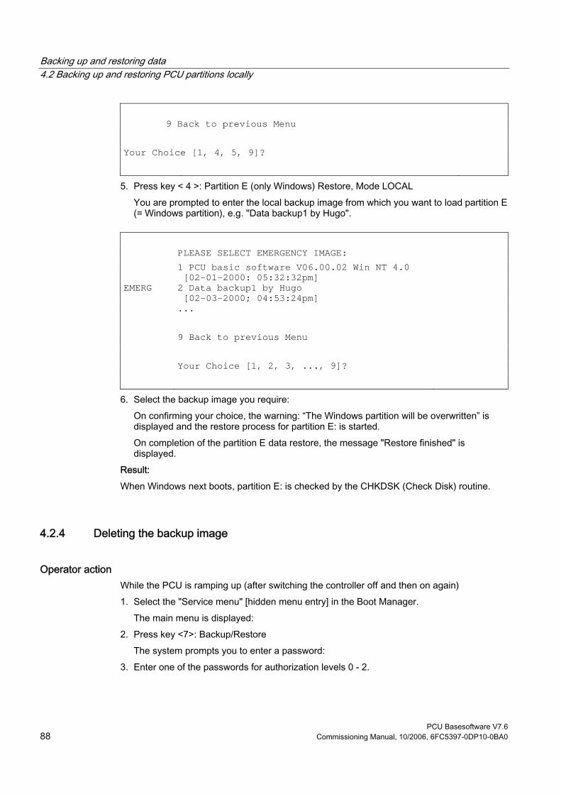
Backing up and restoring data 4.2 Backing up and restoring PCU partitions locally
PCU Basesoftware V7.6 88 Commissioning Manual, 10/2006, 6FC5397-0DP10-0BA0
9 Back to previous Menu Your Choice [1, 4, 5, 9]?
5. Press key < 4 >: Partition E (only Windows) Restore, Mode LOCAL You are prompted to enter the local backup image from which you want to load partition E (= Windows partition), e.g. "Data backup1 by Hugo".
PLEASE SELECT EMERGENCY IMAGE: 1 PCU basic software V06.00.02 Win NT 4.0
[02-01-2000: 05:32:32pm]
EMERG 2 Data backup1 by Hugo [02-03-2000; 04:53:24pm]
... 9 Back to previous Menu Your Choice [1, 2, 3, ..., 9]?
6. Select the backup image you require: On confirming your choice, the warning: “The Windows partition will be overwritten” is displayed and the restore process for partition E: is started. On completion of the partition E data restore, the message "Restore finished" is displayed.
Result: When Windows next boots, partition E: is checked by the CHKDSK (Check Disk) routine.
4.2.4 Deleting the backup image
Operator action While the PCU is ramping up (after switching the controller off and then on again) 1. Select the "Service menu" [hidden menu entry] in the Boot Manager.
The main menu is displayed: 2. Press key <7>: Backup/Restore
The system prompts you to enter a password: 3. Enter one of the passwords for authorization levels 0 - 2.
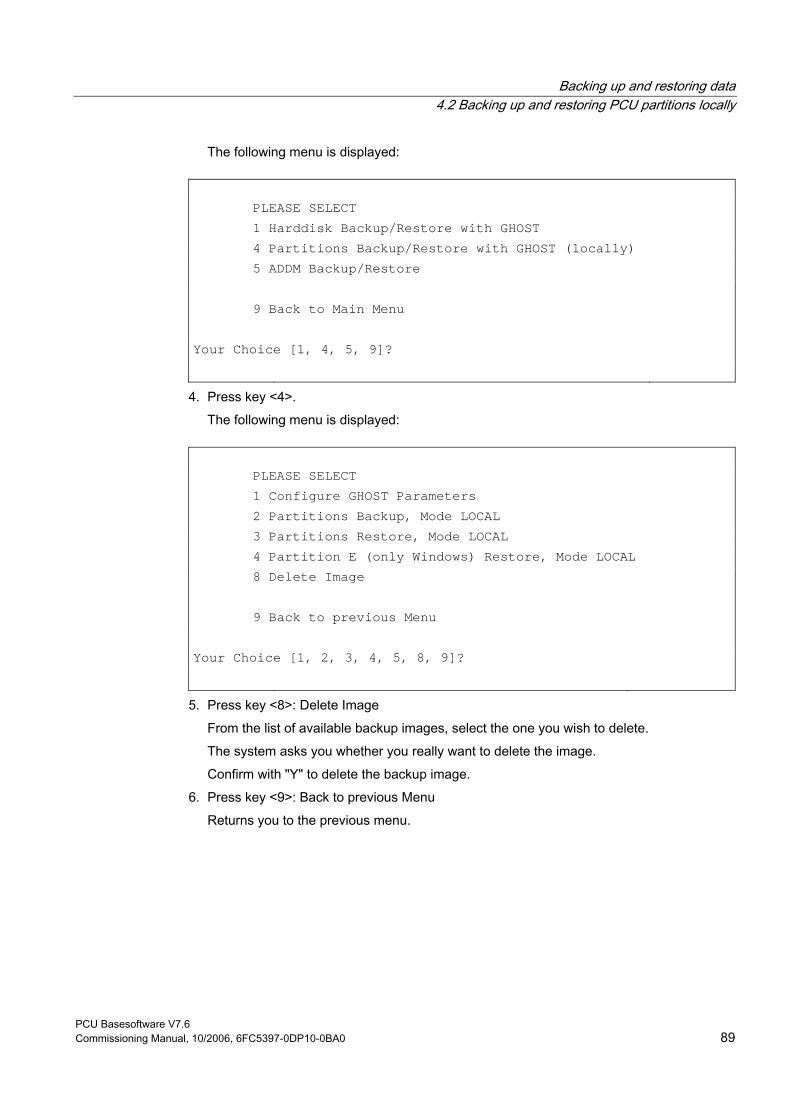
Backing up and restoring data 4.2 Backing up and restoring PCU partitions locally
PCU Basesoftware V7.6 Commissioning Manual, 10/2006, 6FC5397-0DP10-0BA0 89
The following menu is displayed:
PLEASE SELECT 1 Harddisk Backup/Restore with GHOST 4 Partitions Backup/Restore with GHOST (locally) 5 ADDM Backup/Restore 9 Back to Main Menu Your Choice [1, 4, 5, 9]?
4. Press key <4>. The following menu is displayed:
PLEASE SELECT 1 Configure GHOST Parameters 2 Partitions Backup, Mode LOCAL 3 Partitions Restore, Mode LOCAL 4 Partition E (only Windows) Restore, Mode LOCAL 8 Delete Image 9 Back to previous Menu Your Choice [1, 2, 3, 4, 5, 8, 9]?
5. Press key <8>: Delete Image From the list of available backup images, select the one you wish to delete. The system asks you whether you really want to delete the image. Confirm with "Y" to delete the backup image.
6. Press key <9>: Back to previous Menu Returns you to the previous menu.
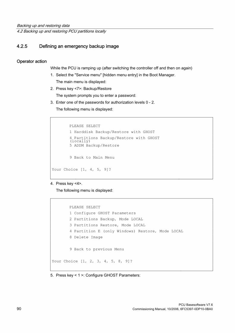
Backing up and restoring data 4.2 Backing up and restoring PCU partitions locally
PCU Basesoftware V7.6 90 Commissioning Manual, 10/2006, 6FC5397-0DP10-0BA0
4.2.5 Defining an emergency backup image
Operator action While the PCU is ramping up (after switching the controller off and then on again) 1. Select the "Service menu" [hidden menu entry] in the Boot Manager.
The main menu is displayed: 2. Press key <7>: Backup/Restore
The system prompts you to enter a password: 3. Enter one of the passwords for authorization levels 0 - 2.
The following menu is displayed:
PLEASE SELECT 1 Harddisk Backup/Restore with GHOST 4 Partitions Backup/Restore with GHOST
(locally)
5 ADDM Backup/Restore 9 Back to Main Menu Your Choice [1, 4, 5, 9]?
4. Press key <4>. The following menu is displayed:
PLEASE SELECT 1 Configure GHOST Parameters 2 Partitions Backup, Mode LOCAL 3 Partitions Restore, Mode LOCAL 4 Partition E (only Windows) Restore, Mode LOCAL 8 Delete Image 9 Back to previous Menu Your Choice [1, 2, 3, 4, 5, 8, 9]?
5. Press key < 1 >: Configure GHOST Parameters:
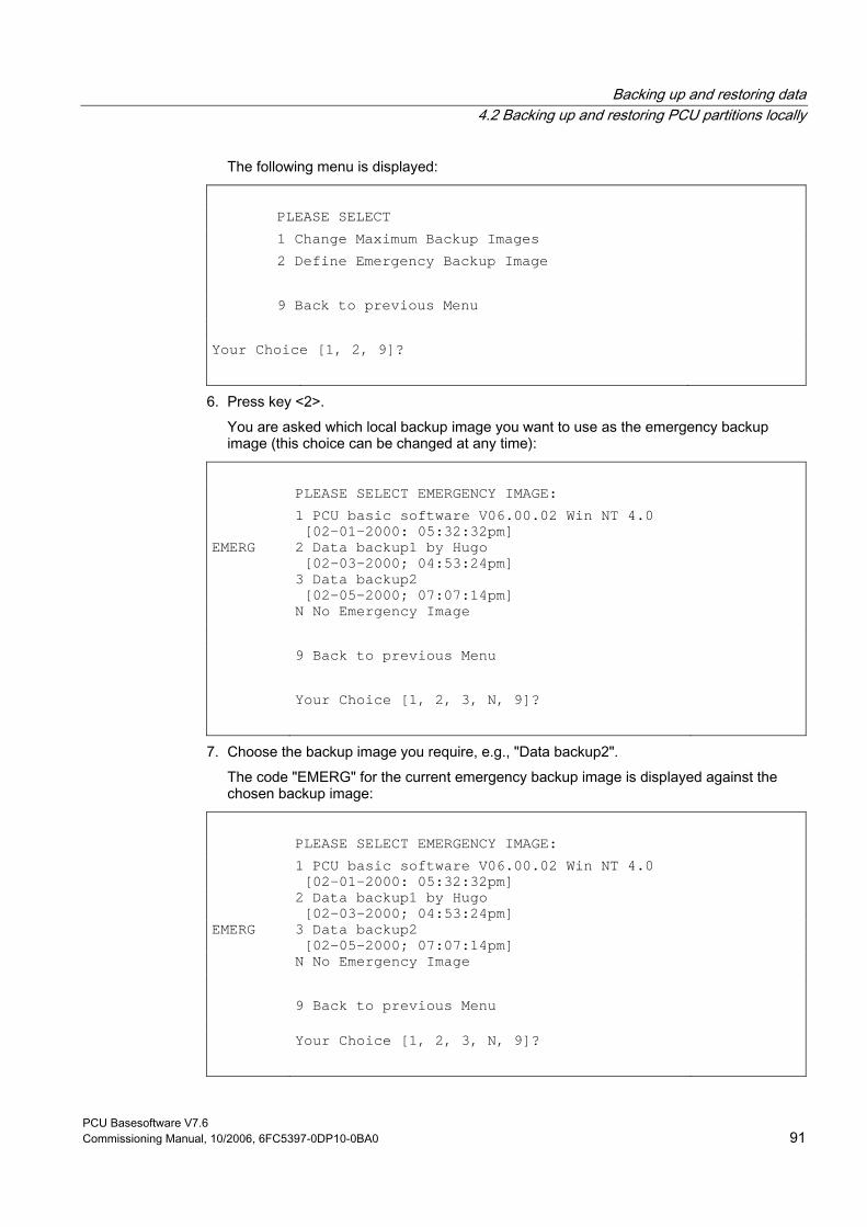
Backing up and restoring data 4.2 Backing up and restoring PCU partitions locally
PCU Basesoftware V7.6 Commissioning Manual, 10/2006, 6FC5397-0DP10-0BA0 91
The following menu is displayed:
PLEASE SELECT 1 Change Maximum Backup Images 2 Define Emergency Backup Image 9 Back to previous Menu Your Choice [1, 2, 9]?
6. Press key <2>. You are asked which local backup image you want to use as the emergency backup image (this choice can be changed at any time):
PLEASE SELECT EMERGENCY IMAGE: 1 PCU basic software V06.00.02 Win NT 4.0
[02-01-2000: 05:32:32pm]
EMERG 2 Data backup1 by Hugo [02-03-2000; 04:53:24pm]
3 Data backup2 [02-05-2000; 07:07:14pm]
N No Emergency Image 9 Back to previous Menu Your Choice [1, 2, 3, N, 9]?
7. Choose the backup image you require, e.g., "Data backup2". The code "EMERG" for the current emergency backup image is displayed against the chosen backup image:
PLEASE SELECT EMERGENCY IMAGE: 1 PCU basic software V06.00.02 Win NT 4.0
[02-01-2000: 05:32:32pm]
2 Data backup1 by Hugo [02-03-2000; 04:53:24pm]
EMERG 3 Data backup2 [02-05-2000; 07:07:14pm]
N No Emergency Image 9 Back to previous Menu Your Choice [1, 2, 3, N, 9]?
Backing up and restoring data 4.2 Backing up and restoring PCU partitions locally
PCU Basesoftware V7.6 92 Commissioning Manual, 10/2006, 6FC5397-0DP10-0BA0
8. Press key < 9 >: Back to previous Menu Returns you to the previous menu.
4.2.6 Restoring the emergency backup on partition E:
Overview If Windows cannot be booted following a system crash or uncontrolled shutdown of the PCU, partition E: can be restored by the defined backup image. • Based on one of the local backup images
Requirement: Password for authorization levels 0-2. • Based on the emergency backup image (provided that a local backup image is defined as
the emergency backup image.) Requirement: Password for authorization levels 0-3 The partition E data restoration by the emergency backup image can be started directly in the main menu.
Note The software for generating emergency boot diskettes is contained in D:\Eboot
Operator action While the PCU is ramping up (after switching the controller off and then on again) 1. Select the "Service menu" [hidden menu entry] in the Boot Manager.
The main menu is displayed: 2. Press key <E>: Restore Windows Partition E (Emergency)
The system prompts you to enter a password: 3. Enter one of the passwords for authorization levels 0 - 3.
– system – Manufacturer – Service – Customer
Result The warning "The Windows Partition E: will be overwritten" is displayed and the restore process for partition E: is started after another prompt. On completion of the partition E data restore, the message "Restore finished" is displayed. When Windows next boots, partition E: is checked by the CHKDSK (Check Disk) routine.
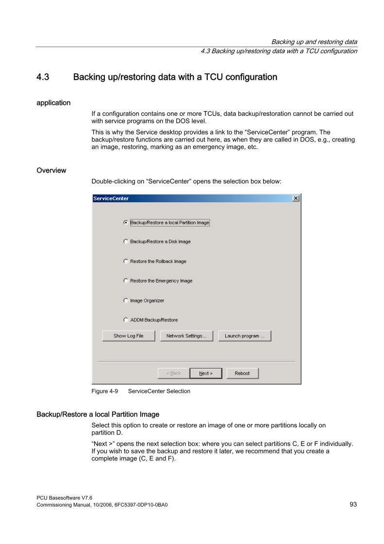
Backing up and restoring data 4.3 Backing up/restoring data with a TCU configuration
PCU Basesoftware V7.6 Commissioning Manual, 10/2006, 6FC5397-0DP10-0BA0 93
4.3 Backing up/restoring data with a TCU configuration
application If a configuration contains one or more TCUs, data backup/restoration cannot be carried out with service programs on the DOS level. This is why the Service desktop provides a link to the “ServiceCenter” program. The backup/restore functions are carried out here, as when they are called in DOS, e.g., creating an image, restoring, marking as an emergency image, etc.
Overview Double-clicking on “ServiceCenter” opens the selection box below:
Figure 4-9 ServiceCenter Selection
Backup/Restore a local Partition Image Select this option to create or restore an image of one or more partitions locally on partition D. “Next >” opens the next selection box: where you can select partitions C, E or F individually. If you wish to save the backup and restore it later, we recommend that you create a complete image (C, E and F).
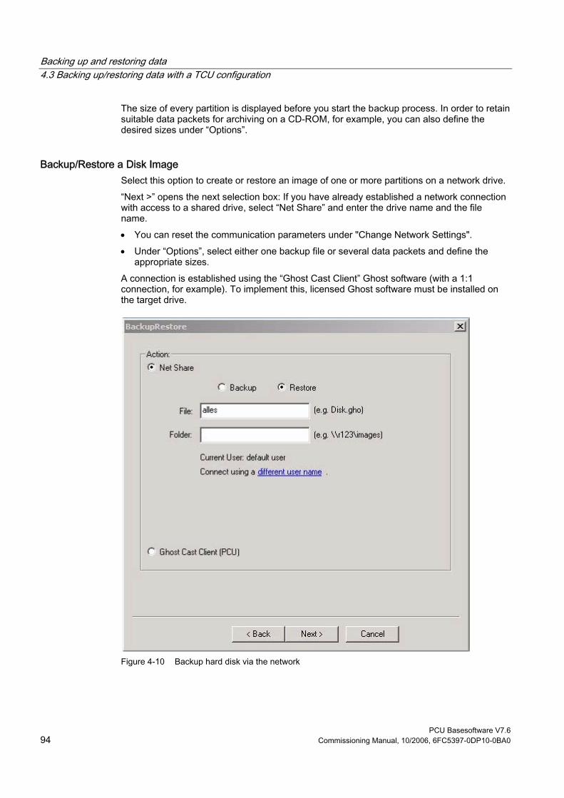
Backing up and restoring data 4.3 Backing up/restoring data with a TCU configuration
PCU Basesoftware V7.6 94 Commissioning Manual, 10/2006, 6FC5397-0DP10-0BA0
The size of every partition is displayed before you start the backup process. In order to retain suitable data packets for archiving on a CD-ROM, for example, you can also define the desired sizes under “Options”.
Backup/Restore a Disk Image Select this option to create or restore an image of one or more partitions on a network drive. “Next >” opens the next selection box: If you have already established a network connection with access to a shared drive, select “Net Share” and enter the drive name and the file name. • You can reset the communication parameters under "Change Network Settings". • Under “Options”, select either one backup file or several data packets and define the
appropriate sizes. A connection is established using the “Ghost Cast Client” Ghost software (with a 1:1 connection, for example). To implement this, licensed Ghost software must be installed on the target drive.
Figure 4-10 Backup hard disk via the network

Backing up and restoring data 4.3 Backing up/restoring data with a TCU configuration
PCU Basesoftware V7.6 Commissioning Manual, 10/2006, 6FC5397-0DP10-0BA0 95
Restore the Rollback Image Select this option to restore a rollback image (the most recently backed up/newest image of partitions C, E and F).
Restore the Emergency Image Select this option to restore the emergency image of one or more partitions. This image is intended for use when the system can no longer be booted after a system crash or uncontrolled shutdown and, therefore, comprises partitions C and E. This image must not impair the execution of installed applications, i.e., the registry entries for all applications installed on F: must be included in the image. Use the “Image Organizer” function to mark the emergency image.
Image Organizer Select this option to mark out one image contained in the displayed list as the emergency image, or to delete an existing image.
ADDM Backup/Restore Select this option to create or restore an image of the ADDM (A & D data management) software on partition D or on a network drive.
Show Backup/Restore Log File This option opens file bacres.txt, which contains a log of all backup records.
Outputting the log file (Service menu “Actionlog” function) The log file can be read out from the booting menu. A booting menu is displayed if the HMI system software has crashed in the control system (PLC: DB19, byte0, bit6). The bit is set and canceled by the PLC on the operator interface (as is key disable, screen blanking, etc.). References:HMI Advanced Startup Manual

Backing up and restoring data 4.3 Backing up/restoring data with a TCU configuration
PCU Basesoftware V7.6 96 Commissioning Manual, 10/2006, 6FC5397-0DP10-0BA0
PCU Basesoftware V7.6 Commissioning Manual, 10/2006, 6FC5397-0DP10-0BA0 97
Index
A Action log log file, 93 Activating the firewall, 8 ADDM (A&D data management), 93
B Backing up partitions, 79, 80 Backing up/restoring data, 67 Backup battery, 40 Backup image, 86 Backup time, 42 Backup/Restore, 90 BIOS
Changing default setting, 22 Start setup, 18 System parameters, 19
Boot screen replace, 34 Storage location, 33
C Change DNS Extension, 25 Change Domain Name, 25 Change Gateway, 25 Change IP Address, 25 Change Machine Name, 25 Change Network Settings, 25 Change Subnetmask, 25 Change TCP/IP settings, 25 Change User Name, 25 Connect to Network Drives, 25 Connection
Ethernet, 67 Parallel, 67
D DHCP server, 7 Disconnect from all Network Drives, 25
Disk image, 90 DNS
Domain name server, 25 server, 64
DOS shell, 31
E Emergency backup, 89 Emergency backup image, 87 Emergency image, 90 Enabling the log, 39 Error log, 39 Ethernet
Connection, 7, 67
F File system
FAT16, 6 NTFS, 6
H Hard disk
battery, 77 partitioning, 6 Replacement, 77
HMI environment Current, 29 Original, 29
HMI Explorer, 31 HMI monitoring, 45
I Install from Floppy Disk, 25 Installing HMI software, 52 Installing SIMATIC STEP 7, 65
M Mains-fed operation, 64

Index
PCU Basesoftware V7.6 98 Commissioning Manual, 10/2006, 6FC5397-0DP10-0BA0
Manage Network Drives, 25
P Partition image, 90 PCU
Delivery condition, 5 IP address, 7 Name (default setting), 7
PCU network name, 74 Post-installing Windows components, 64
R Recovery CD, 64 Recovery Console, 28 Rollback image, 90
S Service Desktop
Background, 34 Mains-fed operation, 64 start, 31
Service menu Functions, 25 parameterizing, 27
ServiceCenter, 90 Show Network Drives, 25 SIMATIC STEP 7
authorizing, 66 SITOP Monitor
Configure, 41 Parameterizing, 42
Software components, 5 Starting OEM programs, 38 System settings, 7
T TCP/IP
Communication, 7 Settings, 62
Toggle protocol, 25
U UPS Module, 40 USB interface, 40 User group, 10 User type, 9 Users (default setting), 8
V Version
Checking software, 31 Software components, 5
W WINS server, 64
Base software and HMI Advanced Commissioning Manual, 11/2006, 6FC5397-0DP10-0BA0 19
Appendix AA.1 Correction sheet - fax template
Should you come across any printing errors when reading this publication, please notify us on this sheet. Suggestions for improvement are also welcome.

Appendix A.1 Correction sheet - fax template
Base software and HMI Advanced 20 Commissioning Manual, 11/2006, 6FC5397-0DP10-0BA0