Banks Monster Exhaust Systemassets.bankspower.com/.../1006/96517-DSL-Grd-Cherokee__ME_v2-web.pdf ·...
12
01/27/15 PN 96517 v.2.0 Banks Monster ® Exhaust System 2014-2015 Jeep Grand Cherokee, 3.0L Diesel THIS MANUAL IS FOR USE WITH MONSTER EXHAUST SYSTEM 51364 Gale Banks Engineering 546 Duggan Avenue • Azusa, CA 91702 (626) 969- 9600 • Fax (626) 334-1743 Product Information & Sales: (888) 635-4565 Customer Support: (888) 839-5600 Installation Support: (888) 839-2700 bankspower.com ©2015 Gale Banks Engineering Owner’s Manual with Installation Instructions
Transcript of Banks Monster Exhaust Systemassets.bankspower.com/.../1006/96517-DSL-Grd-Cherokee__ME_v2-web.pdf ·...

01/27/15 PN 96517 v.2.0
Banks Monster®
Exhaust System
2014-2015 Jeep Grand Cherokee, 3.0L Diesel THIS MANUAL IS FOR USE WITH MONSTER EXHAUST SYSTEM 51364
Gale Banks Engineering 546 Duggan Avenue • Azusa, cA 91702 (626) 969-9600 • Fax (626) 334-1743
Product Information & Sales: (888) 635-4565customer Support: (888) 839-5600 Installation Support: (888) 839-2700
bankspower.com
©2015 Gale Banks Engineering
Owner’s Manualwith Installation Instructions
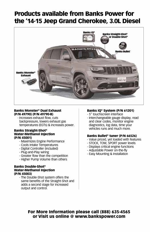
Banks Monster® Dual Exhaust(P/N 49790) (P/N 49790-B)
- Increases exhaust flow, cuts backpressure, lowers exhaust gas temperatures (EGTs) & increases power.
Banks Straight-Shot®
Water-Methanol Injection (P/N 45001)
- Maximizes Engine Performance- cools Intake Temperatures- Digital controller (included)- Plug-and-Play wiring- Greater flow than the competition- Higher Pump Volume than others
Banks Double-Shot®
Water-Methanol Injection(P/N 45003)
- The Double-Shot system offers the same benefits of the Straight-Shot and adds a second stage for increased output and control.
Banks iQ® System (P/N 61201)- 5” touchscreen interface - Interchangeable gauge display, read
and clear codes, monitor engine diagnostics, log data, time your vehicles runs and much more.
Banks Bullet® tuner (P/N 66526)- Value priced, yet loaded with features- STOCK, TOW, SPORT power levels- Displays critical engine functions- Adjustable Power on-the-fly- Easy Mounting & Installation
Products available from Banks Power for the ‘14-15 Jeep Grand Cherokee, 3.0L Diesel
For More Information please call (888) 635-4565 or Visit us online @ www.bankspower.com

96517 v.2.0 3
If you have any questions concerning the installation of your Banks Monster Exhaust System, please call our Technical Service Hotline at (888) 839-2700 between 7:00 am and 4:00 pm (PT). If you have any questions relating to shipping or billing, please contact our Customer Service Department at (888) 839-5600.
Thank you.
1. Before starting work, familiarize yourself with the installation procedure by reading all of the instructions.
2. The exploded view (Figure 1) provides only general guidance. Refer to each step and section diagram in this manual for proper instruction.
3. Throughout this manual, the left side of the vehicle refers to the driver’s side, and the right side to the passenger’s side.
4. Disconnect the negative (ground) cable from the battery (or batteries, if there are two) before beginning work.
5. Route and tie wires and hoses a minimum of 6” away from exhaust heat, moving parts and sharp edges. clearance of 8” or more is recommended where possible.
6. When raising the vehicle, support it on properly weight-rated safety stands, ramps or a commercial hoist. Follow the manufacturer’s safety precautions. Take care to balance the vehicle to prevent it from slipping or falling.
When using ramps, be sure the front wheels are centered squarely on the topsides. When raising the front of the vehicle, put the transmission in park, set the parking brake, and block the rear wheels. When raising the back of the vehicle, be sure the vehicle is on level ground and the front wheels are blocked securely.
Do not use floor jacks to support the vehicle while working under it. Do not raise the vehicle onto concrete blocks, masonry or any other item not intended specifically for this use.
7. During installation, keep the work area clean. Do not allow anything to be dropped into intake, exhaust, or lubrication system components while performing the installation, as foreign objects will cause immediate engine damage upon start-up.
General Installation Practices

4 96517 v.2.0
Tools Required: • 1⁄2” and 3⁄8” drive ratchets with standard and metric sockets and 1⁄2” and 3⁄8” drive extension
• Standard and metric combination or open-end wrenches
• Standard screwdriver
• Clean shop towels or rags
• Pry-bar
Highly recommended tools and supplies: • Foot-pound torque wrench
• Penetrating oil or light lubricant spray
Table of Contents
Section 1 . . . . . . . . . . . . . . . . . . . . . . 5Monster Exhaust Installation
Section 2General Assembly. . . . . . . . . . . . . . . . . 6
96517 v.2.0 5
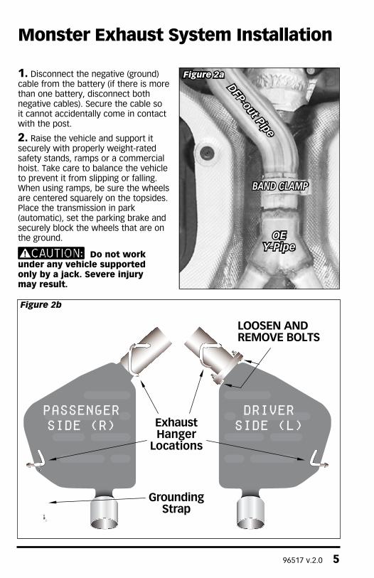
1. Disconnect the negative (ground) cable from the battery (if there is more than one battery, disconnect both negative cables). Secure the cable so it cannot accidentally come in contact with the post.
2. Raise the vehicle and support it securely with properly weight-rated safety stands, ramps or a commercial hoist. Take care to balance the vehicle to prevent it from slipping or falling. When using ramps, be sure the wheels are centered squarely on the topsides. Place the transmission in park (automatic), set the parking brake and securely block the wheels that are on the ground.
Do not work under any vehicle supported only by a jack. Severe injury may result.
Monster Exhaust System Installation
Figure 2a
DFP-out Pipe
OEY-Pipe
BAND CLAMP
DRIVERSIDE (L)
PASSENGERSIDE (r)
LOOSEN ANDREMOVE BOLTS
ExhaustHanger
Locations
GroundingStrap
Figure 2b

6 96517 v.2.0
General Assembly
Figure 1
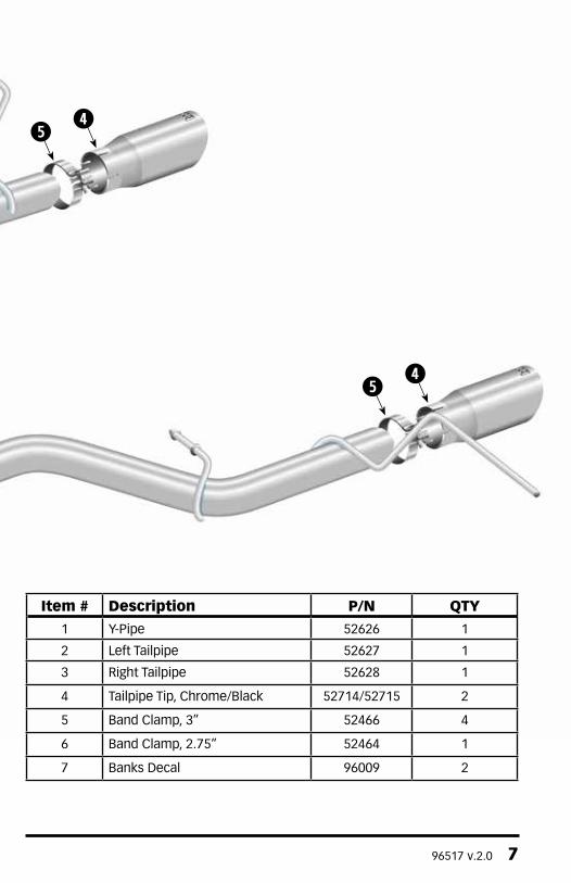
96517 v.2.0 7
Item # Description P/N QTY
1 Y-Pipe 52626 1
2 Left Tailpipe 52627 1
3 Right Tailpipe 52628 1
4 Tailpipe Tip, Chrome/Black 52714/52715 2
5 Band Clamp, 3” 52466 4
6 Band Clamp, 2.75” 52464 1
7 Banks Decal 96009 2

8 96517 v.2.0
OE Alignment PinCorresponding Notch
DPF-outlet pipeMonster Exhaust Y-pipe
Figure 3
3. Loosen band clamp at front of factory y-pipe. Loosen and remove bolts holding left side muffler to tailpipe. See Figure 2a & 2b. Tools used: 15 mm socket & 15mm wrench.
4. Remove the left side muffler / tip assembly by pulling down on the unit to release the hanger pin from the OEM muffler hanger.
5. Disengage the remaining left side and two remaining right side hanger pins from the muffler hangers, then remove the y-pipe and right side muffler / tip assembly from the vehicle by sliding it to the rear. Unclip grounding strap from passenger side hanger. Tools used: Prybar
Spray lubricant may assist in hanger pin removal. Rubber hangers can also be removed from the vehicle to assist in muffler removal.
6. Remove the rear muffler hangers (rubber isolators) from the vehicle and install them onto the rear hanger pins of the Monster Exhaust tailpipes - this
will ease system installation on the vehicle.
All clamps should be positioned at the beginning of the slots (on the 1⁄2 circle punch). Once the pipe/ muffler has been completely engaged in the slip joint, mark the pipe with a scribe or tape for reference when tightening the clamps later in the installation. Mark each slip joint in this fashion.
7. Loosely install the 2.75” band clamp onto the inlet of the Monster Exhaust y-pipe, then install the y-pipe onto the vehicle. The OE alignment tab on the DPF-outlet pipe should fully engage the corresponding notch on the Monster Exhaust Y-Pipe. See Figure 3. Tools used: 15mm socket
8. Loosely install a 3” band clamp onto the inlet of each Monster Exhaust Tailpipe, then install the tailpipes onto the vehicle, fully engaging the Y-Pipe outlet first, then installing the muffler hanger pins/isolators. Reclip grounding strap onto passenger side hanger. Align the tailpipe ends evenly across the rear of the vehicle by adjusting the
96517 v.2.0 9
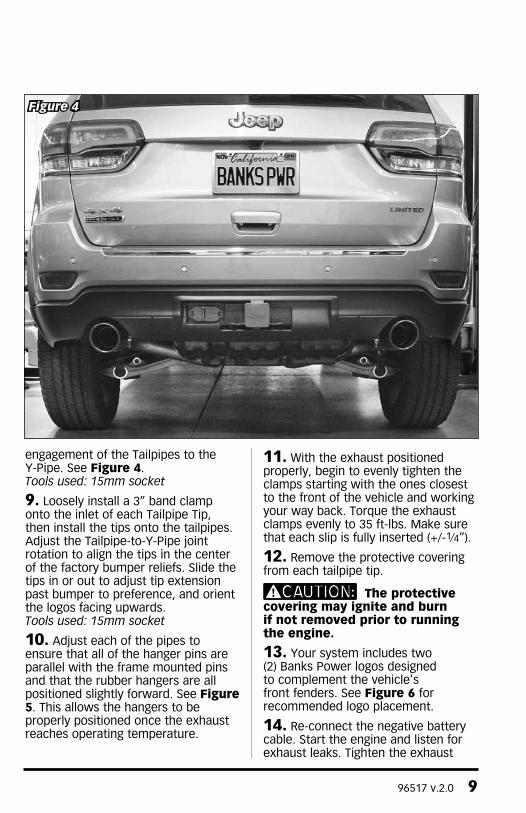
engagement of the Tailpipes to the Y-Pipe. See Figure 4. Tools used: 15mm socket
9. Loosely install a 3” band clamp onto the inlet of each Tailpipe Tip, then install the tips onto the tailpipes. Adjust the Tailpipe-to-Y-Pipe joint rotation to align the tips in the center of the factory bumper reliefs. Slide the tips in or out to adjust tip extension past bumper to preference, and orient the logos facing upwards. Tools used: 15mm socket
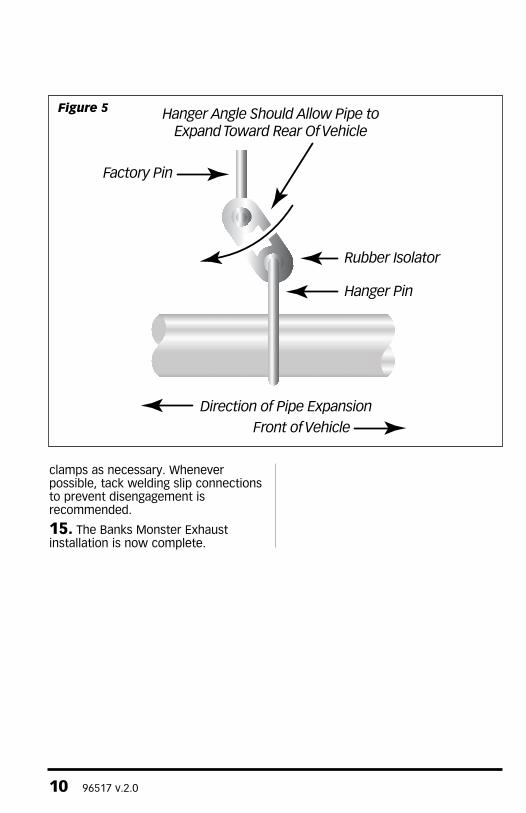
10. Adjust each of the pipes to ensure that all of the hanger pins are parallel with the frame mounted pins and that the rubber hangers are all positioned slightly forward. See Figure 5. This allows the hangers to be properly positioned once the exhaust reaches operating temperature.
11. With the exhaust positioned properly, begin to evenly tighten the clamps starting with the ones closest to the front of the vehicle and working your way back. Torque the exhaust clamps evenly to 35 ft-lbs. Make sure that each slip is fully inserted (+/-1⁄4”).
12. Remove the protective covering from each tailpipe tip.
The protective covering may ignite and burn if not removed prior to running the engine.
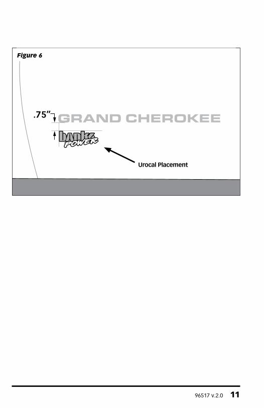
13. Your system includes two (2) Banks Power logos designed to complement the vehicle’s front fenders. See Figure 6 for recommended logo placement.
14. Re-connect the negative battery cable. Start the engine and listen for exhaust leaks. Tighten the exhaust
Figure 4
10 96517 v.2.0
clamps as necessary. Whenever possible, tack welding slip connections to prevent disengagement is recommended.
15. The Banks Monster Exhaust installation is now complete.
Hanger Angle Should Allow Pipe to Expand Toward Rear Of Vehicle
Direction of Pipe Expansion Front of Vehicle
Factory Pin
Hanger Pin
Rubber Isolator
Figure 5
96517 v.2.0 11
Figure 6
Urocal Placement

Gale Banks Engineering 546 Duggan Avenue • Azusa, cA 91702 (626) 969-9600 • Fax (626) 334-1743
Product Information & Sales: (888) 635-4565customer Support: (888) 839-5600 Installation Support: (888) 839-2700
bankspower.com