Bandwidth enhancement of a piezoelectric energy...
11
ICAST2014: 25 nd International Conference on Adaptive Structures and Technologies October 6-8th, 2014, The Hague, The Netherlands 1 ICAST2014 Paper ID 012 Bandwidth enhancement of a piezoelectric energy harvester using parametrically induced vibrations Panduranga Vittal Avvari 1* , Yaowen Yang 2* , Chee Kiong Soh 3 , Liya Zhao 4 1-4 School of Civil and Environmental Engineering, Nanyang Technological University, 50 Nanyang Avenue, Singapore-639798 Abstract A contemporary concept of externally coupling the vibration of a piezoelectric energy harvester with a parametrically excited beam to enhance the bandwidth of the whole system is presented in this paper. The proposed configuration not only serves in enhancing the bandwidth of operation of the harvester but also provides an option to utilize the configuration for a two directional planar vibrations case. This configuration adds a new approach to the extensive research being conducted worldwide in improving the versatility of the piezoelectric energy harvesters. The proposed configuration consists of two simple piezoelectric energy harvesters (made by attaching a macro fiber composite (MFC) patch on a substrate) with unimorph design and having tip masses with embedded cylindrical magnets. The beams are placed with the tip masses facing each other in an L-shaped configuration; when the main harvester is subject to a transverse vibration, the secondary harvester is subjected to a parametric vibration and vice versa if the directions are interchanged. The vibrating beams cause interaction between the magnetic tip masses inducing nonlinear magnetic coupling, thus modifying the linear behaviors. The magnetic tip mass of the parametrically vibrating beam induces changes in the stable equilibrium states of the whole system and also incorporates the off resonance peak due to parametrically induced resonance into the main harvester beam. In the experimental investigations aluminum and fiberglass substrates were used with varying substrate thickness and other variables like, size of the harvester, tip mass, distance between the harvester beams and base acceleration etc. were maintained constant. The whole experimental setup was subject to a frequency sweep in a range of 5-50Hz and the open circuit voltage data was obtained from the vibrating beams for both linear (no magnetic interaction) and nonlinear cases. The results obtained in this study are very promising in enhancing the bandwidth of operation of the piezoelectric energy harvesters and the concept can be extended to a case where in the vibrations from all three dimensions can be utilized in harvesting energy effectively. 1. INTRODUCTION Harvesting energy from surroundings has been a prodding topic for mankind since ancient ages, the water wheel, the wind mills, the greenhouses etc. are a few early examples of energy harvesting for a large scale, in the past few decades enormous emphasis has been laid on the usage of renewable forms of energy * Corresponding authors, [email protected]; [email protected].
Transcript of Bandwidth enhancement of a piezoelectric energy...

ICAST2014: 25nd
International Conference on Adaptive Structures and Technologies October 6-8th, 2014, The Hague, The Netherlands
1
ICAST2014 Paper ID 012
Bandwidth enhancement of a piezoelectric energy harvester using parametrically induced vibrations
Panduranga Vittal Avvari1*, Yaowen Yang2*, Chee Kiong Soh3, Liya Zhao4
1-4 School of Civil and Environmental Engineering, Nanyang Technological University, 50 Nanyang Avenue,
Singapore-639798
Abstract
A contemporary concept of externally coupling the vibration of a piezoelectric energy harvester with a
parametrically excited beam to enhance the bandwidth of the whole system is presented in this paper. The
proposed configuration not only serves in enhancing the bandwidth of operation of the harvester but also
provides an option to utilize the configuration for a two directional planar vibrations case. This
configuration adds a new approach to the extensive research being conducted worldwide in improving the
versatility of the piezoelectric energy harvesters. The proposed configuration consists of two simple
piezoelectric energy harvesters (made by attaching a macro fiber composite (MFC) patch on a substrate)
with unimorph design and having tip masses with embedded cylindrical magnets. The beams are placed
with the tip masses facing each other in an L-shaped configuration; when the main harvester is subject to a
transverse vibration, the secondary harvester is subjected to a parametric vibration and vice versa if the
directions are interchanged. The vibrating beams cause interaction between the magnetic tip masses
inducing nonlinear magnetic coupling, thus modifying the linear behaviors. The magnetic tip mass of the
parametrically vibrating beam induces changes in the stable equilibrium states of the whole system and
also incorporates the off resonance peak due to parametrically induced resonance into the main harvester
beam. In the experimental investigations aluminum and fiberglass substrates were used with varying
substrate thickness and other variables like, size of the harvester, tip mass, distance between the harvester
beams and base acceleration etc. were maintained constant. The whole experimental setup was subject to a
frequency sweep in a range of 5-50Hz and the open circuit voltage data was obtained from the vibrating
beams for both linear (no magnetic interaction) and nonlinear cases. The results obtained in this study are
very promising in enhancing the bandwidth of operation of the piezoelectric energy harvesters and the
concept can be extended to a case where in the vibrations from all three dimensions can be utilized in
harvesting energy effectively.
1. INTRODUCTION
Harvesting energy from surroundings has been a prodding topic for mankind since ancient ages, the
water wheel, the wind mills, the greenhouses etc. are a few early examples of energy harvesting for a large
scale, in the past few decades enormous emphasis has been laid on the usage of renewable forms of energy
* Corresponding authors, [email protected]; [email protected].

ICAST2014: 25nd
International Conference on Adaptive Structures and Technologies October 6-8th, 2014, The Hague, The Netherlands
2
[6]. Though these have primarily served the energy crisis for a larger scale of power production, there is a
major scope for research in the domain of small scale energy harvesting in the order of 50mW and lower.
With the emergence of low power electronics and sensor devices, a tremendous challenge has been
conferred upon researchers to pack enough energy in the minimum available space, leading a revolution in
battery technology [6-10]. But the major drawback of using batteries is the periodic replacement of the
batteries for continued functioning of the electronics. This limitation has been addressed by the
development of small scale energy harvesting techniques; the usage of electrostatic, electromagnetic,
solar, piezoelectric etc. has provided a means to harness energy for low power systems on a long term
basis [6-8]. Of the above mentioned methods piezoelectric energy harvesting (PEH) provides an added
advantage of high power density for the given material volume [6].
Over the last decade, there has been substantial development in the realm of PEH; various designs
were reported in the literature stating the added benefits of each design [6-10]. The initial harvester
designs consisted of a transversely vibrating cantilever beam with a piezoelectric element attached at the
root of the beam [6]. This was the simplest designs and had a major drawback owing to a narrow
bandwidth of operational frequency. This was overcome by the introduction of magnets at the tip of the
beam, L-shaped beam designs etc... [3,5,6,10] Researchers have even investigated the application of the
basic cantilever designs for axial mode of vibrations, this results in a parametric vibration of the cantilever
beam (the concepts of transverse and parametric vibrations of a PEH system have been presented in the
succeeding sections) [1,2,4,7]. Thus, to further contribute to the effort of numerous researchers working in
the area of widening the bandwidth of operation of energy harvesters, a contemporary design utilizing
both the transverse and the parametric vibrations to enhance the bandwidth of a PEH system has been
presented in this paper. The proposed design consists of a simple cantilever flexural member (main beam)
undergoing transverse vibrations and a secondary cantilever flexural member (auxiliary beam) undergoing
parametric vibration, the auxiliary beam subjects the system to an off resonance peak thereby enhancing
the bandwidth of operation for the whole system.
This paper consists of five sections; the first section gives a brief introduction about energy harvesting
and the various methods and means that were explored over the years. The second section deals with the
concepts of transverse and parametric vibrations, and the lumped parameter equations available for each
of these cases. The third section introduces the potential energy variation of the proposed system, giving
an account of the formulation involved and the plots showing the variation of potential energy for
different cases. The fourth section discusses the experimental investigation of the proposed system and the
concurrent observations and their significance. The last section concludes the paper identifying the major
contributions from the present study and presenting the key areas for future work.
2. TRANSVERSE AND PARAMETRIC VIBRATIONS
A brief overview of transverse and parametric vibrations has been discussed in this section. When an
external excitation is applied out of the plane of beading for a flexural member, the member is subjected to
a transverse vibration. Similarly, when an external excitation is applied along the axial direction of a
flexural member, the member undergoes transverse instability at a frequency twice its modal frequencies
and this is known as the principle parametric resonance; this was first reported by Faraday in 1831and
investigated by many researchers after that [2-4]. Fig. 1 shows the transverse and the parametric vibrations
of a simple cantilever beam.

ICAST2014: 25nd
International Conference on Adaptive Structures and Technologies October 6-8th, 2014, The Hague, The Netherlands
3
(a) Beam under transverse vibrations (b) Beam under parametric vibrations
Figure 1. Layout of transverse and parametric vibrations
These vibrations have been studied in detail over the years and the mathematical expressions for a
lumped parameter formulation for these vibrations are presented in eq. 1 and eq. 2 [6,4,7,10].
)()()(2)( 2 twfttt brrrrrrr (1)
Where,
1
)()(),(r
rr txtxw
eqreq
eqrreq
eqreq
rt
L
req
L
req
rt
L
req
MfF
MC
MK
LMdxxxmF
dxxxEIK
LMdxxxmM
2
)()()(
)()(
)()()(
2
0
0
2
2
0
2
In the above expression, w(x,t) is the displacement of the beam in generalized co-ordinates, x being the
horizontal axis and y the vertical axis. The displacement is represented as a summation of the modal co-
ordinates ϕ and a function of time η, and r being the rth mode of vibration. Meq, Keq, Ceq, Feq are the
equivalent modal mass, stiffness, damping and force respectively. E is the Young‟s modulus of the beam
material, I is the moment of inertia of the beam cross section, m is the mass per unit length of the beam, Mt
is tip mass and ωr is the modal frequency of the rth mode.
)cos()(22 2232
21 t
m
Fuuuuuuuuuuu
eq
n (2)
In the above expression, u(x,t) is the displacement of the beam in generalized co-ordinates in x
direction and time t, μ1 and μ2 are the viscous and quadratic (air drag) damping terms respectively, α and β
are constants and the terms containing them represent the cubic nonlinearities and inertial nonlinearities,
meq is the equivalent mass of the system and, F and ω are the amplitude and excitation frequency of the
forcing function, and ωn represents the natural frequency of the system. It is interesting to note that, in the
absence of the nonlinearities, quadratic damping term, and external forcing function, the equation reduces

ICAST2014: 25nd
International Conference on Adaptive Structures and Technologies October 6-8th, 2014, The Hague, The Netherlands
4
to that of a free vibration case of a linear transverse vibrating member. Thus, the parametric vibration is
caused due to the inherent nonlinearities in the member, and the presence of an external forcing function
drives the flexural member into parametric resonance.
There are several mathematical techniques outlined in the literature for solving the expressions stated
above, of these the perturbations techniques like method of multiple scales, harmonic balance are
popularly used for parametric vibrations and frequency domain or time domain modal analysis methods
are used for transverse vibrations [1,2,4,7].
3. POTENTIAL ENERGY DISTRIBUTION OF A COMBINED SYSTEM
The potential energy of a system of magnets can be expressed using many different formulations, for
the present system the enhanced integral formulation will be used [9-11]. As the magnets play a vital role
in determining the behavior of the present system in consideration, it is of utmost importance to use a
good degree of accuracy in the formulation of the magnetic interaction in order to get a comprehensive
picture of the effect of magnets on the proposed system, the conventional dipole equations do not provide
a great degree of accuracy at close distances of the order of the size of the magnets [9,11]. Fig. 2 shows a
typical representation of two magnets and the corresponding expressions are elucidated in Eq. 3.
Figure 2. Representation of two magnets „x‟ m and „y‟ m axial and lateral separation respectively
0
12
2
11
2
02212121 ),()(),( dqqxUqJ
q
qR
RJ
R
yqJRRMMyxE o
(3)
Where,
2221
21
22 2222
),(R
qx
R
qxdd
R
qxd
R
qxd
eeeeqxU
ionconfigurat repulsivefor 1
ionconfigurat attractivefor 1
2,1,2
it
d ii
21,
2, ),(
2
1
EEE
tLwKE
beamPotentialPotential
eqbeamPotential (4)

ICAST2014: 25nd
International Conference on Adaptive Structures and Technologies October 6-8th, 2014, The Hague, The Netherlands
5
In the above expression, E1-2 is the magnetic interaction energy between the magnets 1 and 2; μo is the
magnetic permeability of vacuum; M1 and M2 are the saturation magnetizations of magnets 1 and 2,
respectively; R1 and R2 are the radii of the cylindrical magnets; Jo and J1 are the modified Bessel functions
of the first type of order 0 and 1, respectively; y is the lateral separation between the magnetic axes, x is
the axial separation between the end of the magnets, the Bessel functions of q define the shape of the
magnets and ti is the height of the cylindrical magnets. EPotential,beam is the potential energy of the beam
expressed in terms of equivalent beam stiffness Keq and the displacement of the tip of the beam w(L,t). As
there is no available solution for the integral in the magnetic interaction energy equation, it was solved
numerically using MATLAB.
(a) Case I: When the auxiliary beam is fixed
(d) Potential energy distribution and deflection of
the corresponding beams
(b) Case II: Both the beams are in sychronized
motion
(c) Case III: Both the beams are not in
synchronized motion
(e) Potential energy distribution for the whole
system for respective cases
Figure 3. (a) – (c) Layout of three possible scenarios of the system, (d) – (e) Representation of the
potential energy distribution for the system.
The interaction energy of the magnets contributes to the potential energy of the whole system, for
better representation of the effect of the magnets, a system consisting of two cantilever beams with

ICAST2014: 25nd
International Conference on Adaptive Structures and Technologies October 6-8th, 2014, The Hague, The Netherlands
6
embedded tip masses facing each other as shown in fig. 3 is considered. For simplicity the potential
energy of the beams resulting from the stiffness of the beam material and the interaction energy of the
magnets is summated numerically as expressed in Eq. 4, and the resulting variation of potential energy at
different positions of the tip masses are shown graphically. Moreover, the variation of potential energy for
three possible cases of vibration is also enumerated for clear understanding. Case-I exhibits the situation
when the magnet on the member undergoing parametric vibration i.e. the auxiliary beam is considered to
be static and the member undergoing transverse vibration i.e. the main beam vibrates due to the external
periodic force. Case-II deals with a situation where both the beams undergo vibration and the vibration of
the beams is synchronized with respect to each other and Case-III portrays the situation where the
vibration of the beams is completely out of sync. These three cases illustrate the possible extreme
scenarios for the vibration of the beams, thus when the beams are subject to an external excitation, the
potential energy distribution for the system is likely to fall in between the curves shown in fig. 3.
Based on the above discussion and Fig. 3, it is evident that the presence of the auxiliary beam which
vibrates parametrically causes a change in the potential energy of the main beam and vice versa thus
inducing nonlinearity into the system. This nonlinear variation of energy results in widening of the
bandwidth of the output open circuit voltage (VO) and output power (PO) obtained from the vibration of
the cantilever PEH system as discussed in the following section.
4. EXPERIMENTAL INVESTIGATION OF THE PROPOSED DESIGN
The proposed concept of enhancing the bandwidth of VO and PO of a linear cantilever PEH with the
help of an externally vibrating cantilever beam undergoing parametric vibrations, and consisting of
magnetic tip masses is discussed in this section.
The experimental setup consists of two beams placed perpendicular to each other as shown in fig. 4,
the main beam was placed perpendicular to the direction of excitation and undergoes transverse
vibrations; the auxiliary beam was placed parallel to the direction of excitation undergoing parametric
vibration. MFC patches were attached to the root of the beams and the voltage produced was monitored
using National Instruments (NI) Voltage DAQ card having an internal resistance of 1MOhm. In order to
lower the natural frequencies and tune the first harmonic vibration, the beams were attached with tip
masses. The tip masses were embedded with magnets thus inducing non-linearity into the system. The
beams were supported on a frame which was in turn fixed to the moving arm of the shaker. The whole
experimental setup for both linear case and nonlinear case is as shown in fig. 5.
Figure 4. Layout of experimental setup

ICAST2014: 25nd
International Conference on Adaptive Structures and Technologies October 6-8th, 2014, The Hague, The Netherlands
7
(a) Experimental setup – linear configuration (b) Experimental setup – non-linear configuration
Figure 5. Experimental setup of the proposed system
The PEH system was subject to external excitation with the help of a seismic shaker. The excitation of
the shaker was controlled using a feedback mechanism, an accelerometer was used to monitor the
excitation and send the signal back to the computer, the computer was connected to a signal generator and
the necessary modifications to the drive signal were implemented from time to time and these were sent to
the shaker through the shaker amplifier. Thus, the necessary level of sinusoidal excitation was monitored
and maintained. During the course of the experiments, the whole system was subjected to a varying
magnitude of excitation levels of 0.1g (1g = 9.81m/s2) and 0.2g, within a frequency range of 5Hz to 50Hz.
A total of two types of beam materials were tested (fiber glass and aluminum), the properties of the beams
are displayed in table 1. For each set of beams, an initial setup consisting of a linear configuration was
used followed by a nonlinear configuration with the magnets placed at a distance ‘x’ from each other
under rest conditions and the magnets were tested for both attractive and repulsive configurations. The
two types of beam materials were used to investigate the range of applicability of the proposed bandwidth
enhancement method over different materials and configurations.
Table 1 Properties of the beams
Beam Fiberglass Aluminum Tip mass Magnet properties
Main beam 90mm x 10mm x
0.76mm
90mm x 10mm x
0.635mm 8.162g
NdFeB – N42, 8mmϕ
and 15mm thk
Auxiliary beam 90mm x 10mm x
0.76mm
90mm x 10mm x
0.4mm 6.865g
NdFeB – N35, 6mmϕ
and 2mm thk
Experiments were performed by placing magnets at x = 15mm and x = 10mm apart, but the effect of
nonlinearity wasn‟t so prominent at x = 15mm, so the results obtained from x = 10mm are shown in this
section. Fig. 6 displays the plots for output open circuit voltage (VO) for a linear configuration of the
system and the variation of the peaks of both main and auxiliary beams; it is interesting to note that in
fiberglass beams the VO peaks are much lower compared to that of the aluminum beams and the
positioning of the peaks is much different, this is a direct indicator of the strain present in the beams for a
same level of excitation. In fiberglass beams, as both the beams have similar cross section areas the peak
for the auxiliary beam occurs at a higher frequency than the main beam, this supports the explanation
about the primary parametric resonant frequency which occurs at about twice the first natural harmonic
frequency [1,4,7]. Similarly, the presence of a thinner auxiliary aluminum beam results in a primary
parametric resonant frequency which occurs at a lower frequency in comparison with the first harmonic
Linear configuration
Excitation
Shaker arm
Accelerometer
Auxiliary beam
Main beam
Non-linear configuration
Shaker arm
Accelerometer
Auxiliary beam
Main beam
ICAST2014: 25nd
International Conference on Adaptive Structures and Technologies October 6-8th, 2014, The Hague, The Netherlands
8
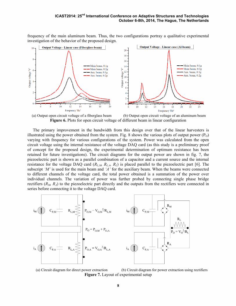
frequency of the main aluminum beam. Thus, the two configurations portray a qualitative experimental
investigation of the behavior of the proposed design.
(a) Output open circuit voltage of a fiberglass beam (b) Output open circuit voltage of an aluminum beam
Figure 6. Plots for open circuit voltage of different beam in linear configuration
The primary improvement in the bandwidth from this design over that of the linear harvesters is
illustrated using the power obtained from the system. Fig. 8 shows the various plots of output power (PO)
varying with frequency for various configurations of the system. Power was calculated from the open
circuit voltage using the internal resistance of the voltage DAQ card (as this study is a preliminary proof
of concept for the proposed design, the experimental determination of optimum resistance has been
retained for future investigations). The circuit diagrams for the output power are shown in fig. 7, the
piezoelectric part is shown as a parallel combination of a capacitor and a current source and the internal
resistance for the voltage DAQ card (RL,M, RL,A, RL) is placed parallel to the piezoelectric part [6]. The
subscript ‘M’ is used for the main beam and ‘A’ for the auxiliary beam. When the beams were connected
to different channels of the voltage card, the total power obtained is a summation of the power over
individual channels. The variation of power was further probed by connecting single phase bridge
rectifiers (RM, RA) to the piezoelectric part directly and the outputs from the rectifiers were connected in
series before connecting it to the voltage DAQ card.
(a) Circuit diagram for direct power extraction (b) Circuit diagram for power extraction using rectifiers
Figure 7. Layout of experimental setup

ICAST2014: 25nd
International Conference on Adaptive Structures and Technologies October 6-8th, 2014, The Hague, The Netherlands
9
The first two graphs on power distribution present a significant variation in the magnitude for the
fiberglass and the aluminum beams. Secondly, the nonlinear behavior when magnets were placed in
attractive configuration for the fiberglass beams provided an increased bandwidth at 10μW (about 10% of
the peak) in comparison with the repulsive configuration; whereas, in the case of the aluminum beams the
attractive configuration hardly provided any power as the magnets got stuck due to the flexible auxiliary
beam. Moreover, in both the configurations the peak power output is slightly enhanced and the bandwidth
is considerably increased by more than 100% at a level of 10% the peak PO in all cases. The aluminum
beams were further investigated by attaching rectifiers, there is almost 20% drop in the peak power due to
the presence of rectifiers, yet a similar trend in enhancement of the peak power and shift in resonant
frequencies for both the main and auxiliary beams was observed. Moreover, the bandwidth and the
average power (area under the curve) are also enhanced; the presence of two resonant frequencies close to
each other and the effect of internal resonance have been discussed in the literature [3], this is the
fundamental reason for the enhancement of the bandwidth using the proposed design. The major drawback
from the usage of the rectifiers for the aluminum beams is attributed to the cancellation and interference
from the main and auxiliary beams, thus there is a considerable dip in between both the peaks, this can be
overcome by extracting power from both the beams separately by using energy harvesting circuitry and
summing them up at the end. These aspects of the experimental investigations will be considered for
detailed analysis in the future works.
(a) Output power for a fiberglass beam (b) Output power for an aluminum beam
(c) Output power for an aluminum beam using rectifiers
Figure 8. Plots for output power of the beams in both linear and nonlinear configurations

ICAST2014: 25nd
International Conference on Adaptive Structures and Technologies October 6-8th, 2014, The Hague, The Netherlands
10
5. CONCLUSIONS
The present study illustrates a contemporary design for a PEH system which consists of two flexural
members undergoing transverse and parametric vibrations respectively, and are coupled together using
magnets. Piezoelectric MFC transducers are attached to both the beams and the resonant frequencies of
the beams complement each other with the added nonlinearity from the magnets to give an enhanced
bandwidth of the output power distribution. Moreover, in comparison with a linear case the nonlinear
configuration has a relatively higher peak and a higher average power distribution too. A qualitative
experimental analysis was performed by testing two types of beam material, resulting in parametric
resonant peaks on either side of the resonant peaks obtained for the main beams. It was observed that the
aluminum beams produce higher output voltage and output power due to the higher modulus of elasticity
and the aluminum beams are more effective for a repulsive configuration of magnets, and the fiberglass
beams are more effective for an attractive case. In short, the effectiveness of the configuration of magnets
can be determined depending on the stiffness of the main and auxiliary beams and their corresponding
natural and parametric resonant frequencies. The connections for the output voltage and power were also
investigated; on rectification of the output voltage from the beams, though there is increment in the
bandwidth by about 100% the peaks drop by about 20% and the bandwidth decreases in comparison with
the non-rectified case. Thus, for a PEH system consisting of two or more sources of power, a circuit
configuration to derive power separately is more advantageous than combining the sources directly.
Further, the harvesters can be optimally tuned to perform efficiently when the direction of excitation is
interchanged, this can be achieved in a system where the natural harmonics of the vibrating members are
close enough to cause internal resonance between two different modes of vibration. In the present study,
the fiberglass beams with closer natural harmonics and coupled magnetic interactions are more suitable
for such interchange of directions; the aluminum beams need appropriate tuning for such a scenario.
REFERENCES
1. Haquang, N., Mook, D. T., and Plaut, R. H., “Non-linear structural vibrations under combined
parametric and external excitations,” Journal of sound and vibration, Vol. 118, No. 2, Oct. 1987,
pp. 291-306.
2. Jia, Y., Yan, J., Soga, K., and Seshia, A. A., “A parametrically excited vibration energy
harvester,” Journal of intelligent material systems and structures, Vol. 25, No. 3, Feb. 2009, pp.
278-289.
3. Erturk, A., Renno, J. M., and Inman, D. J., “Modeling of piezoelectric energy harvesting from an
L-shaped beam-mass structure with an application to UAVs,” Journal of intelligent material
systems and structures, Vol. 20, No. 5, March 2009, pp. 529-544.
4. Daqaq, M. F., Stabler, C., Qaroush, Y., and Seuaciuc-Osorio, T., “Investigation of power
harvesting via parametric excitations,” Journal of intelligent material systems and structures, Vol.
20, No. 5, March 2009, pp. 545-557.
5. Xu, J. W., Wei Wei, S., Kong, F. R., and Zhi Hua, F., “Right-angle piezoelectric cantilever with
improved energy harvesting efficiency,” Applied physics letters, Vol. 96, No. 15, April 2010, pp.
152904-152904.
6. Erturk, A., and Inman, D. J., “Piezoelectric energy harvesting,” 1st ed., A John Wiley and Sons,
Ltd., Publication, United Kingdom, 2011.
7. Abdelkefi, A., Nayfeh, A. H., and Hajj, M. R., “Global nonlinear distributed-parameter model of
parametrically excited piezoelectric energy harvesters,” Nonlinear Dynamics, Vol. 67, No. 2, Jan.
2012, pp. 1147-1160.

ICAST2014: 25nd
International Conference on Adaptive Structures and Technologies October 6-8th, 2014, The Hague, The Netherlands
11
8. Szarka, G. D., Stark, B. H., and Burrow, S. G., “Review of power conditioning for kinetic energy
harvesting systems,” IEEE transactions on power electronics, Vol. 27, No. 2, Feb. 2012, pp. 803-
815.
9. Vokoun, D., Beleggia, M., and Heller, L., “Magnetic guns with cylindrical permanent magnets,”
Journal of Magnetism and Magnetic materials, Vol. 324, No. 9, May 2012, pp. 1715-1719.
10. Tang, L., Yang, Y., and Soh, C. K., “Toward broadband vibration-based energy harvesting,”
Journal of intelligent material systems and structures, Vol. 21, No. 18, Sept. 2012, pp. 1867-1897.
11. Avvari, P. V., Tang, L., Yang, Y., and Soh, C. K., “Enhancement of piezoelectric energy
harvesting with multi-stable nonlinear vibrations,” Proc. SPIE: Active and Passive Smart
Structures and Integrated Systems, San Diego, USA, Vol. 8688, March 2013, pp. 86882H.