Ballytherm BTF Floor Insulation Ballytherm BTCW Rebated ... · The Irish Agrément Board is...
34
CERTIFICATE NO.05/0220 Ballytherm Limited Annagh Industrial Park , Ballyconnell, Co Cavan, Ireland. Tel: +353 (0)49 9527000 Fax: +353 (0)49 9527002 Email: [email protected] Website: www.ballytherm.ie Ballytherm BTF Floor Insulation Ballytherm BTCW Rebated Cavity Wall Insulation Ballytherm BTDL Dry Lining Board Insulation Ballytherm BTR Pitch Roof Insulation Isolation de murs Wärmedämmung PRODUCT DESCRIPTION: This Certificate relates to the following products: ■ BTF – Ballytherm Floor Insulation (Detail Sheet 1) ■ BTCW – Ballytherm Rebated Cavity Wall Insulation (Detail Sheet 2) ■ BTDL – Ballytherm Dry Lining Board Insulation (Detail Sheet 3) ■ BTR – Ballytherm Pitch Roof Insulation (Detail Sheet 4) MANUFACTURE AND MARKETING: Ballytherm Limited Annagh Industrial Park, Ballyconnell Co Cavan, Ireland Tel: +353 (0) 49 9527000 Fax: +353 (0) 49 9527002 e-mail: [email protected] Website: www.ballytherm.ie CI/SfB Kn6 The Irish Agrément Board is designated by Government to issue European Technical Approvals. Irish Agrément Board Certificates establish proof that the certified products are ‘proper materials’ suitable for their intended use under Irish site conditions, and in accordance with the Building Regulations 1997 to 2002. The Irish Agrément Board operates in association with the National Standards Authority of Ireland (NSAI) as the National Member of UEAtc. Readers are advised to check that this Certificate has not been withdrawn or superseded by a later issue by contacting the Irish Agrément Board, NSAI, Glasnevin, Dublin 9 or online at www.irishagrememtboard.com/certs.php?no=050220
Transcript of Ballytherm BTF Floor Insulation Ballytherm BTCW Rebated ... · The Irish Agrément Board is...

CERTIFICATE NO.05/0220Ballytherm Limited Annagh Industrial Park ,Ballyconnell, Co Cavan, Ireland.Tel: +353 (0)49 9527000 Fax: +353 (0)49 9527002Email: [email protected]: www.ballytherm.ie
Ballytherm BTF Floor Insulation Ballytherm BTCW Rebated Cavity Wall InsulationBallytherm BTDL Dry Lining Board Insulation Ballytherm BTR Pitch Roof Insulation Isolation de mursWärmedämmung
PRODUCT DESCRIPTION:
This Certificate relates to the following products:
■ BTF – Ballytherm Floor Insulation (Detail Sheet 1)
■ BTCW – Ballytherm Rebated Cavity Wall Insulation
(Detail Sheet 2)
■ BTDL – Ballytherm Dry Lining Board Insulation
(Detail Sheet 3)
■ BTR – Ballytherm Pitch Roof Insulation (Detail Sheet 4)
MANUFACTURE AND MARKETING:
Ballytherm Limited
Annagh Industrial Park, Ballyconnell
Co Cavan, Ireland
Tel: +353 (0) 49 9527000
Fax: +353 (0) 49 9527002
e-mail: [email protected]
Website: www.ballytherm.ie
CI/SfB Kn6
The Irish Agrément Board is designated by Government to issue European Technical Approvals.
Irish Agrément Board Certificates establish proof that the certified products are ‘proper materials’ suitable for their
intended use under Irish site conditions, and in accordance with the Building Regulations 1997 to 2002.
The Irish Agrément Board operates in association with
the National Standards Authority of Ireland (NSAI) as the National Member of UEAtc.
Readers are advised to check that this Certificate has not been withdrawn or superseded by a later issue by contacting the Irish Agrément Board, NSAI, Glasnevin, Dublin 9 or online at www.irishagrememtboard.com/certs.php?no=050220
Certificate No.05/0220 / Ballytherm BTF, BTCW, BTDL & BTR Insulation.2
Part One / Certification 1
1.1 ASSESSMENTIn the opinion of the Irish Agrément Board (IAB),
Ballytherm Insulation panels described in this general
Certificate when used in conjunction with the
relevant Detail Sheet, and if used in accordance with
this Certificate, meet the requirements of the
Building Regulations 1997 - 2002 as indicated in
Section 1.2 of this Certificate.
1.2 BUILDING REGULATIONS 1997 to 2002
REQUIREMENT:
Part D – Materials and WorkmanshipD3 – Ballytherm Insulation panels as certified in this
Irish Agrément Certificate comprise proper materials
fit for their intended use (See Part 4 of this
Certificate).
D1 – Ballytherm Insulation panels, as certified in this
Certificate, meet the requirements of the building
regulations for workmanship.
Part B – Fire Safety
B2 – Internal Fire Spread (Linings)
Ballytherm Insulation panels faced with plasterboard
are considered to be Class 0. It may therefore be used
on the internal surfaces of buildings of every purpose
group.
Ballytherm insulation panels faced with low
emmissivity aluminium foil facings are declared to be
Class 1 to BS 476 Part 7: 1987.
Part C – Site Preparation and Resistance to Moisture
C4 – Resistance to Weather and Ground Moisture
Ballytherm Insulation panels referred to in this
Certificate when installed in compliance with the
conditions indicated in Part 2 of the relevant Detail
Sheet will not promote the passage of moisture and
will minimise the risk of surface of interstitial
condensation.
Part J – Heat Producing Appliances
J3 – Protection of Building
In the opinion of the Irish Agrément Board (IAB) the
Ballytherm Insulation panels, if used in accordance
with this Certificate and the TGD Part J – Heat
producing Appliances, meet the requirements of the
Building Regulations 1997 to 2002.
Part L – Conservation of Fuel and Energy
L1 - Conservation of fuel and energy
Based on the measured thermal conductivity of the
Ballytherm Insulation panels referred to in this
certificate and detailed in the relevant “Detail Sheet”,
the current ‘U Value’ requirements can be achieved.

Certificate No.05/0220 / Ballytherm BTF, BTCW, BTDL & BTR Insulation. 3
2.1 PRODUCT DESCRIPTIONEach type of Ballytherm Insulation Panel is given a
detailed description in the relevant “Data Sheet”
related to its use.
2.2 DELIVERY, STORAGE AND MARKINGBallytherm Insulation Panels are supplied palletised
in labelled packs and shrink wrapped in polyethylene.
Each pack carries a label with the product
description, product characteristics (� and R values),
size, thickness, batch number and date of manufacture,
the manufacturer’s name, IAB identification mark and
IAB Certificate number for the system.
The product packaging must not be considered
adequate for outside protection and boards should
be stored undercover, upright in a clean dry flat area
because paper facings may become loose if the boards
are exposed to damp conditions for extended periods.
Boards should be protected in transit and in storage
from damage caused by ropes and tie straps.
Installation instructions and details outlining the
steps necessary to ensure proper installation are
included in each pack
The boards must not be exposed to a naked flame or
other ignition sources.
On-site cutting of boards where it is necessary to
maintain continuity of insulation around doors,
windows or other openings is easily executed using a
fine tooth saw or by cutting through the insulation.
Cutting BTDL panels is also easy to execute by using
a trimming knife to cut through the insulation and
paper backing of the plasterboard layer, then
snapping the board face down over a straight edge
and cutting the paper facing of the plasterboard on
the other side.
Tapered edged boards are jointed and finished in
accordance with standard dry lining procedure
offering a surface suitable for paper hanging and
paint finishes.
Good workmanship and appropriate site procedures
are necessary to achieve expected thermal and air
tightness performance. Ensure accurate trimming to
achieve close butting joints and continuity of insulation.
Adequate protection and safety precautions should
be taken.
Part Two / Technical Specification and Control Data 2

Certificate No.05/0220 / Ballytherm BTF, BTCW, BTDL & BTR Insulation.4
3.1 GENERALThis matter is dealt with for each product in their
Detail Sheet.
Part Three / Design Data 3
Certificate No.05/0220 / Ballytherm BTF, BTCW, BTDL & BTR Insulation. 5
4.1 BEHAVIOUR IN FIREEach “Detail Sheet” contains the relevant information.
4.2 WATER PENETRATION4.2.1 Ballytherm Insulation Panels referred to in this
Certificate are of a closed cell structure, which do not
allow water uptake by capillary action.
4.2.2 Ballytherm Insulation panels referred to in this
Certificate, when used in accordance with this
Certificate present no significant risk of water
penetration.
4.3 THERMAL INSULATIONThe aged/design thermal conductivity ‘�’ value' of
Ballytherm Insulation panels, BTF floor Insulation, BTCW
cavity wall insulation, and BTR pitch roof insulation is
0.022 W/mK. The aged/design thermal conductivity ‘�’
value of Ballytherm BTDL dry lining board insulation is
0.026 W/mK when measured in accordance with I.S. EN
12667 :2000 ‘Thermal performance of building materialsand products – Determination of thermal resistance bymeans of guarded hot plate and heat flow metersmethod – Products of high and medium thermalresistance’. The high thermal resistance of Ballytherm
Insulation panels ensures that cold bridging and extra
heat loss around the edges of openings can be avoided.
Lintel jamb and cill designs similar to those shown in
Diagram 3 of the TGD to Part L – Conservation of Fuel
and Energy (DWELLINGS), (Building Regulations 2002),
will be satisfactory to limit thermal bridging.
Uncontrolled leakage of air through the fabric of a
building and/or cracks in and around door and window
frames, sills, jambs etc. air movement due to thermal
effects or due to wind pressure can occur. Details of
how to avoid the infiltration of cold air are given in TGD
– L (Dwellings), Section 1.6.
The required maximum U-values for external walls,
floors and roofs can be obtained by reference to the
relevant “Detail Sheets”.
4.4 MATERIALS IN CONTACT WITH ELECTRICAL WIRINGElectrical installations should be in accordance with the
ETCI publication ET 207: 2003 Guide to the National
Rules for Electrical Installations as Applicable to
Domestic Installations. It is recommended that cables
should not be buried in the insulation and carried in a
conduit. In relation to recessed spotlights and other
luminaries, ET 207 requires they be not less than the
minimum distances from combustible materials as
specified in clause 559.3.2 of the TCI National rules of
the Electro Technical Council of Ireland (ET 101). For extra
low voltage (ELV) it is recommended that only surface
mounted ELV lighting be permitted in conjunction with
Ballytherm BTDL Dry Lining Board insulation.
4.5 CONDENSATION RISKBallytherm Insulation Panels referred to in this
certificate have a high vapour resistance and are
therefore unlikely to be affected by surface or
interstitial condensation, provided all joints between
boards are taped and in the case of Ballytherm BTDL
Dry Lining board filled and taped in accordance with
standard Dry Lining practice. Interstitial condensation
analysis for average winter environmental conditions
for cavity wall constructions indicate no condensation
risk. When insulating buildings the recommendations
of BS 5250: 2002 Code of practice for control of
condensation in buildings should be followed to
minimise the risk of condensation within the building
elements and structures. While no vapour check would
be necessary it would be prudent to use a separate
vapour check in ceiling insulation in high humidity
areas such as kitchens and bathrooms. The vapour
check could be installed between the BTR insulation
and the Ballytherm BTDL Dry Lining board.
4.6 RESISTANCE TO SOLVENTS, FUNGI AND RODENTSBallytherm Insulation Panels referred to in this
certificate do not promote infestation, as there is no
food value in the materials used. They also resist attack
by mould and microbial growth. The insulation is not
resistant to some solvent-based adhesive systems,
particularly those containing methyl ethyl keytone.
Adhesives containing such solvents should not be used
in association with the boards. The insulation core is
however resistant to dilute acids, alkalis, mineral oil and
petrol.
Boards which have been in contact with harsh solvents,
petrol, mineral oil or acids or boards that have been
damaged in any other way should not be used.
4.7 WALL MOUNTED FITTINGSThis matter is dealt with in the “Detail Sheets”.
4.8 MAINTENANCEThis matter is dealt with in the ”Detail Sheets”.
4.9 DURABILITYBallytherm Insulation Panels referred to in this
certificate are rot-proof and durable. As insulation for
cavity walls, roofs, floors and as a dry lining such
products are judged to be stable and will remain
effective as an insulation system for the life of the
building, so long as it is installed in accordance with
this certificate. Ballytherm BTDL Dry Lining board
should not be used to isolate dampness nor be used in
continuously damp or humid conditions.
Part Four / Technical Investigations 4

Certificate No.05/0220 / Ballytherm BTF, BTCW, BTDL & BTR Insulation.6
5.1 National Standards Authority of Ireland ("NSAI")
following consultation with the Irish Agrément Board
("IAB") has assessed the performance and method of
installation of the product/process and the quality of
the materials used in its manufacture and certifies
the product/process to be fit for the use for which it
is certified provided that it is manufactured, installed,
used and maintained in accordance with the descriptions
and specifications set out in this Certificate and in
accordance with the manufacturer's instructions and
usual trade practice. This Certificate shall remain
valid for five years so long as:
(a) the specification of the product is unchanged.
(b)the Building Regulations 1997 to 2002 and
any other regulation or standard applicable
to the product/process, its use or installation
remains unchanged.
(c) the product continues to be assessed for the
quality of its manufacture and marking by NSAI.
(d) no new information becomes available which in
the opinion of the NSAI, would preclude the
granting of the Certificate.
(e) the product or process continues to be manufactured,
installed, used and maintained in accordance with
the description, specifications and safety
recommendations set out in this certificate.
(f) the registration and/or surveillance fees due to
IAB are paid.
5.2 The IAB mark and certification number may only be
used on or in relation to product/processes in respect
of which a valid Certificate exists. If the Certificate
becomes invalid the Certificate holder must not use
the IAB mark and certification number and must
remove them from the products already marked.
5.3 In granting Certification, the NSAI makes no
representation as to;
(a) the absence or presence of patent rights
subsisting in the product/process; or
(b)the legal right of the Certificate holder to market,
install or maintain the product/process; or
(c) whether individual products have been
manufactured or installed by the Certificate
holder in accordance with the descriptions
and specifications set out in this Certificate.
5.4 This Certificate does not comprise installation
instructions and does not replace the manufacturer's
directions or any professional or trade advice relating
to use and installation which may be appropriate.
5.5 Any recommendations contained in this Certificate
relating to the safe use of the certified product/process
are preconditions to the validity of the Certificate.
However the NSAI does not certify that the
manufacture or installation of the certified product
or process in accordance with the descriptions and
specifications set out in this Certificate will satisfy
the requirements of the Safety, Health and Welfare at
Work Act. 1989, or of any other current or future
common law duty of care owed by the manufacturer
or by the Certificate holder.
5.6 The NSAI is not responsible to any person or body
for loss or damage including personal injury arising
as a direct or indirect result of the use of this
product or process.
5.7 Where reference is made in this Certificate to any
Act of the Oireachtas, Regulation made thereunder,
Statutory Instrument, Code of Practice, National
Standards, Manufacturer's instructions, or similar
publication, it shall be construed as reference to such
publication in the form in which it is in force at the
date of this Certification.
Part Five / Conditions of Certification 5
Certificate No.05/0220 / Ballytherm BTF, BTCW, BTDL & BTR Insulation. 7
THE IRISH AGRÉMENT BOARD THE IRISH AGRÉMENT BOARD THE IRISH AGRÉMENT BOARD THE IRISH AGRÉMENT BOARD THE IRISH AGRÉMENT BOARD THE IRISHAGRÉMENT BOARD THE IRISH AGRÉMENT BOARD THE IRISH AGRÉMENT BOARD THE IRISH AGRÉMENT BOARD THE IRISH AGRÉMENT BOARD THE IRISH AGRÉMENTBOARD THE IRISH AGRÉMENT BOARD THE IRISH AGRÉMENT BOARD THE IRISH AGRÉMENT BOARD THE IRISH AGRÉMENT BOARD THE IRISH AGRÉMENT BOARDTHE IRISH AGRÉMENT BOARD THE IRISH AGRÉMENT BOARD THE IRISH AGRÉMENT BOARD THE IRISH AGRÉMENT BOARD THE IRISH AGRÉMENT BOARD THE IRISHAGRÉMENT BOARD THE IRISH AGRÉMENT BOARD THE IRISH AGRÉMENT BOARD THE IRISH AGRÉMENT BOARD THE IRISH AGRÉMENT BOARD THE IRISH AGRÉMENTBOARD THE IRISH AGRÉMENT BOARD THE IRISH AGRÉMENT BOARD THE IRISH AGRÉMENT BOARD THE IRISH AGRÉMENT BOARD THE IRISH AGRÉMENT BOARDTHE IRISH AGRÉMENT BOARD THE IRISH AGRÉMENT BOARD THE IRISH AGRÉMENT BOARD THE IRISH AGRÉMENT BOARD THE IRISH AGRÉMENT BOARD THE IRISHAGRÉMENT BOARD THE IRISH AGRÉMENT BOARD THE IRISH AGRÉMENT BOARD THE IRISH AGRÉMENT BOARD THE IRISH AGRÉMENT BOARD THE IRISH AGRÉMENTBOARD THE IRISH AGRÉMENT BOARD THE IRISH AGRÉMENT BOARD THE IRISH AGRÉMENT BOARD THE IRISH AGRÉMENT BOARD THE IRISH AGRÉMENT BOARDTHE IRISH AGRÉMENT BOARD THE IRISH AGRÉMENT BOARD THE IRISH AGRÉMENT BOARD THE IRISH AGRÉMENT BOARD THE IRISH AGRÉMENT BOARD THE IRISHAGRÉMENT BOARD THE IRISH AGRÉMENT BOARD THE IRISH AGRÉMENT BOARD THE IRISH AGRÉMENT BOARD THE IRISH AGRÉMENT BOARD THE IRISH AGRÉMENTBOARD THE IRISH AGRÉMENT BOARD THE IRISH AGRÉMENT BOARD THE IRISH AGRÉMENT BOARD THE IRISH AGRÉMENT BOARD THE IRISH AGRÉMENT BOARDTHE IRISH AGRÉMENT BOARD THE IRISH AGRÉMENT BOARD THE IRISH AGRÉMENT BOARD THE IRISH AGRÉMENT BOARD THE IRISH AGRÉMENT BOARD THE IRISHAGRÉMENT BOARD THE IRISH AGRÉMENT BOARD THE IRISH AGRÉMENT BOARD THE IRISH AGRÉMENT BOARD THE IRISH AGRÉMENT BOARD THE IRISH AGRÉMENTBOARD THE IRISH AGRÉMENT BOARD THE IRISH AGRÉMENT BOARD THE IRISH AGRÉMENT BOARD THE IRISH AGRÉMENT BOARD THE IRISH AGRÉMENT BOARDTHE IRISH AGRÉMENT BOARD THE IRISH AGRÉMENT BOARD THE IRISH AGRÉMENT BOARD THE IRISH AGRÉMENT BOARD THE IRISH AGRÉMENT BOARD THE IRISHAGRÉMENT BOARD THE IRISH AGRÉMENT BOARD THE IRISH AGRÉMENT BOARD THE IRISH AGRÉMENT BOARD THE IRISH AGRÉMENT BOARD THE IRISH AGRÉMENTBOARD THE IRISH AGRÉMENT BOARD THE IRISH AGRÉMENT BOARD THE IRISH AGRÉMENT BOARD THE IRISH AGRÉMENT BOARD THE IRISH AGRÉMENT BOARDTHE IRISH AGRÉMENT BOARD THE IRISH AGRÉMENT BOARD THE IRISH AGRÉMENT BOARD THE IRISH AGRÉMENT BOARD THE IRISH AGRÉMENT BOARD THE IRISHAGRÉMENT BOARD THE IRISH AGRÉMENT BOARD THE IRISH AGRÉMENT BOARD THE IRISH AGRÉMENT BOARD THE IRISH AGRÉMENT BOARD THE IRISH AGRÉMENTBOARD THE IRISH AGRÉMENT BOARD THE IRISH AGRÉMENT BOARD THE IRISH AGRÉMENT BOARD THE IRISH AGRÉMENT BOARD THE IRISH AGRÉMENT BOARDTHE IRISH AGRÉMENT BOARD THE IRISH AGRÉMENT BOARD THE IRISH AGRÉMENT BOARD THE IRISH AGRÉMENT BOARD THE IRISH AGRÉMENT BOARD THE IRISHAGRÉMENT BOARD THE IRISH AGRÉMENT BOARD THE IRISH AGRÉMENT BOARD THE IRISH AGRÉMENT BOARD THE IRISH AGRÉMENT BOARD THE IRISH AGRÉMENTBOARD THE IRISH AGRÉMENT BOARD THE IRISH AGRÉMENT BOARD THE IRISH AGRÉMENT BOARD THE IRISH AGRÉMENT BOARD THE IRISH AGRÉMENT BOARDTHE IRISH AGRÉMENT BOARD THE IRISH AGRÉMENT BOARD THE IRISH AGRÉMENT BOARD THE IRISH AGRÉMENT BOARD THE IRISH AGRÉMENT BOARD THE IRISHAGRÉMENT BOARD THE IRISH AGRÉMENT BOARD THE IRISH AGRÉMENT BOARD THE IRISH AGRÉMENT BOARD THE IRISH AGRÉMENT BOARD THE IRISH AGRÉMENTBOARD THE IRISH AGRÉMENT BOARD THE IRISH AGRÉMENT BOARD THE IRISH AGRÉMENT BOARD THE IRISH AGRÉMENT BOARD THE IRISH AGRÉMENT BOARDTHE IRISH AGRÉMENT BOARD THE IRISH AGRÉMENT BOARD THE IRISH AGRÉMENT BOARD THE IRISH AGRÉMENT BOARD THE IRISH AGRÉMENT BOARD THE IRISHAGRÉMENT BOARD THE IRISH AGRÉMENT BOARD THE IRISH AGRÉMENT BOARD THE IRISH AGRÉMENT BOARD THE IRISH AGRÉMENT BOARD THE IRISH AGRÉMENTBOARD THE IRISH AGRÉMENT BOARD THE IRISH AGRÉMENT BOARD THE IRISH AGRÉMENT BOARD THE IRISH AGRÉMENT BOARD THE IRISH AGRÉMENT BOARDTHE IRISH AGRÉMENT BOARD THE IRISH AGRÉMENT BOARD THE IRISH AGRÉMENT BOARD THE IRISH AGRÉMENT BOARD THE IRISH AGRÉMENT BOARD THE IRISHAGRÉMENT BOARD THE IRISH AGRÉMENT BOARD THE IRISH AGRÉMENT BOARD THE IRISH AGRÉMENT BOARD THE IRISH AGRÉMENT BOARD THE IRISH AGRÉMENTBOARD THE IRISH AGRÉMENT BOARD THE IRISH AGRÉMENT BOARD THE IRISH AGRÉMENT BOARD THE IRISH AGRÉMENT BOARD THE IRISH AGRÉMENT BOARDTHE IRISH AGRÉMENT BOARD THE IRISH AGRÉMENT BOARD THE IRISH AGRÉMENT BOARD THE IRISH AGRÉMENT BOARD THE IRISH AGRÉMENT BOARD THE IRISHAGRÉMENT BOARD THE IRISH AGRÉMENT BOARD THE IRISH AGRÉMENT BOARD THE IRISH AGRÉMENT BOARD THE IRISH AGRÉMENT BOARD THE IRISH AGRÉMENTBOARD THE IRISH AGRÉMENT BOARD THE IRISH AGRÉMENT BOARD THE IRISH AGRÉMENT BOARD THE IRISH AGRÉMENT BOARD THE IRISH AGRÉMENT BOARDTHE IRISH AGRÉMENT BOARD THE IRISH AGRÉMENT BOARD THE IRISH AGRÉMENT BOARD THE IRISH AGRÉMENT BOARD THE IRISH AGRÉMENT BOARD THE IRISHAGRÉMENT BOARD THE IRISH AGRÉMENT BOARD THE IRISH AGRÉMENT BOARD THE IRISH AGRÉMENT BOARD THE IRISH AGRÉMENT BOARD THE IRISH AGRÉMENTBOARD THE IRISH AGRÉMENT BOARD THE IRISH AGRÉMENT BOARD THE IRISH AGRÉMENT BOARD THE IRISH AGRÉMENT BOARD THE IRISH AGRÉMENT BOARDTHE IRISH AGRÉMENT BOARD THE IRISH AGRÉMENT BOARD THE IRISH AGRÉMENT BOARD THE IRISH AGRÉMENT BOARD THE IRISH AGRÉMENT BOARD THE IRISHAGRÉMENT BOARD THE IRISH AGRÉMENT BOARD THE IRISH AGRÉMENT BOARD THE IRISH AGRÉMENT BOARD THE IRISH AGRÉMENT BOARD THE IRISH AGRÉMENTBOARD THE IRISH AGRÉMENT BOARD THE IRISH AGRÉMENT BOARD THE IRISH AGRÉMENT BOARD THE IRISH AGRÉMENT BOARD THE IRISH AGRÉMENT BOARD THE IRISH AGRÉMENT BOARD THE IRISH AGRÉMENT BOARD THE IRISH AGRÉMENT BOARD THE IRISH AGRÉMENT BOARD THE IRISH AGRÉMENT BOARD THE IRISH
This Certificate No. 05/0220 is accordingly granted by the NSAI to Ballytherm Ltd on behalf of
The Irish Agrément Board.
Date of Issue: May 2005
Signed
Chief Executive, NSAI
Readers may check that the status of this Certificate has not changed by contacting the Irish Agrément Board,
NSAI, Glasnevin, Dublin 9, Ireland. Telephone: (01) 807 3800. Fax: (01) 807 3842. www.nsai.ie
The Irish Agrément Board
Certificate No. 05/0220 Detail Sheet 1 / Ballytherm BTF Floor Insulation8
MANUFACTURE AND MARKETING:
The product is manufactured and marketed by:
Ballytherm Limited
Annagh Industrial Park, Ballyconnell
Co Cavan, Ireland
Tel: +353 (0) 49 9527000
Fax: +353 (0) 49 9527002
e-mail: [email protected]
Website: www.ballytherm.ie
Detail Sheet 1 / Ballytherm BTF Floor Insulation
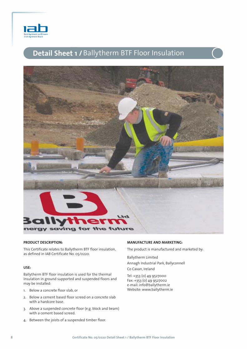
PRODUCT DESCRIPTION:
This Certificate relates to Ballytherm BTF floor insulation,
as defined in IAB Certificate No. 05/0220.
USE:
Ballytherm BTF floor insulation is used for the thermal
insulation in ground supported and suspended floors and
may be installed:
1. Below a concrete floor slab, or
2. Below a cement based floor screed on a concrete slab
with a hardcore base.
3. Above a suspended concrete floor (e.g. block and beam)
with a cement based screed.
4. Between the joists of a suspended timber floor.

Certificate No. 05/0220 Detail Sheet 1 / Ballytherm BTF Floor Insulation 9
1.1 PRODUCT DESCRIPTIONThis Certificate relates to the Ballytherm BTF floor
insulation using Polyisocyanurate (PIR), closed cell
rigid foam insulation manufactured in accordance
with I.S. EN 13165: 2001 Thermal insulation productsfor buildings – Factory made products of polyurethanefoam (PUR) Specification. During the manufacturing
process, liquid raw materials expanded by blowing
agents are applied between low emissivity tri-
laminate foil facings. Ballytherm BTF floor insulation
boards are CFC and HCFC free and therefore have
zero ozone depletion potential.
This Certificate certifies compliance with the
requirements of the Building Regulations 1997 to 2002.
Table 1 shows the Ballytherm BTF floor insulation,
product range.
1.2 MANUFACTUREBallytherm BTF floor insulation is manufactured from
a formulation of chemicals, which are sprayed onto
low emissivity composite foil facings subsequently
autohesively bonded to the insulation core during
manufacture.
1.3 INSTALLATION1.3.1 General
Ballytherm BTF floor insulation boards are placed
below the slab or between the slab and the screed.
Boards can also be used to provide insulation to
suspended timber floors. Vertical upstands of
insulation (perimeter insulation strips) should be
used to separate the screed/slab from the wall to
reduce thermal bridging at the wall/floor junction.
Refer to clause 0.6 (General) and 1.5 (Thermal Bridging)
of Technical Guidance Document L to Building
Regulations 2002 – Conservation of Fuel and Energy
1.3.2 Procedure – Laying below the floor screed Where Ballytherm BTF floor insulation board is used
below the floor screed, it is simply laid loose over the
concrete floor slab with the necessary water and
vapour protection. Board joints should be lightly
butted, staggered and laid to break-bonded pattern.
The floor slab should be uniformly flat without steps
or gaps to provide continuous bearing support to the
Ballytherm BTF floor insulation board. A strip of board
25 mm thick should be used around the perimeter of
the floor area being insulated. This should be placed
vertically against the abutting wall so that it
connects with the insulation laid over the slab and
protects the edge of the screed, so preventing cold
bridging of the floor screed. Boards are overlaid with
a separating layer of polythene sheet (not less then
500 gauge) or building paper to BS 1521: 1972 –
Specification for Waterproof Building Papers, Grade
B1F, between the screed and the Ballytherm BTF floor
insulation board to prevent the wet screed
penetrating joints between the boards. The minimum
thickness of sand and cement screed is 65 mm for
domestic construction and 75 mm for most other
buildings.
Floor loading on non domestic applications should be
verified by a Chartered Engineer.
The concrete floor over which the insulation is to be
laid should be left as long as possible to maximise
drying out in accordance with the relevant
recommendations of BS 8203: 2001, Code of practicefor the installation of resilient floor coverings.
1.3.3 Procedure –Laying below the floor slab Where Ballytherm BTF floor insulation board is used
below the floor slab, lay the hardcore in layers; min
150 – 225 mm; each layer should be well compacted,
with the surfaced blinded with a thin layer of sand to
provide a suitable surface for laying a damp proof
membrane (dpm) or radon barrier.
A damp proof membrane e.g. 1200 gauge polythene
or a Radon Barrier, subject to site conditions and
statutory requirements, should be laid over the well
compacted hardcore and blinding with joints taped
and folded to prevent the passage of ground
moisture. The dpm should be carried up the
surrounding foundation walls until it meets and seals
with the damp proof course.
Ballytherm BTF floor insulation board should be laid
staggered to break-bonded pattern with closely
butted joints, fitted tightly at the edges and around
any service penetrations.
A strip of board 25 mm thick should be used around
the perimeter of the floor slab in order to prevent
cold bridging of the slab. Boards are overlaid with a
separating layer of polythene sheet (not less then
500 gauge) or building paper to BS 1521: 1972 –
Specification for Waterproof Building Papers, Grade B1F.
Table 1: Product Range
The boards are available in the following sizes:
Length 2400m
Width 1200mm
Thickness 25, 30, 35, 40, 45, 50,
60, 70, and 75mm
Grade PIR
Part One / Technical Specification and Control Data 1

Certificate No. 05/0220 Detail Sheet 1 / Ballytherm BTF Floor Insulation10
Care should be taken to avoid damage to the
insulation or damp proof membranes and radon
barriers as the slab is being poured and operatives
should make use of barrow runs and walkways whilst
installation progresses.
A vapour barrier is to be provided over the insulation
board to prevent condensation damage from cold
bridging.
1.3.4 Procedure – Laying on precast block and beam floorAll surfaces should be level to accept the Ballytherm
BTF floor insulation board. The floor surface should be
smooth, uneven surfaces should be levelled prior to
laying of the floor and flat irregularities should be
removed by a levelling screed. Lay a Damp Proof
Membrane, ensure that it is correctly positioned and
turned up to meet the seal with the dpc.
Ballytherm BTF floor insulation board should be laid
with joints tightly butted. During construction the
boards must be protected from damage by moisture
sources, water spillage, plaster droppings etc. Use
scaffold boards to prevent wheelbarrow and other
traffic damage to the boards. Ballytherm BTF floor
insulation board should be over laid with 500 gauge
polythene sheet to prevent the wet screed from
penetrating the joints between the insulation boards.
As in the case with solid ground floors, attention
should be given to detailing to avoid thermal
bridging.
1.3.5 Laying in suspended timber floors The application of Ballytherm BTF floor insulation
board in suspended floor constructions should be
carried out before commencement of floor boarding.
Ballytherm BTF floor insulation board should be cut
to fit snugly between the timber joists. It should be
supported on softwood timber battens, proprietary
galvanised steel saddle clips or galvanised nails partly
driven into the side of the joists. Battens/nails should
be placed at an appropriate height to suit the
thickness of board being employed and nails should
remain 40 mm proud of the joist. The board should
then be laid between the joists so that they are
supported by the battens, clips or nails. Any narrow
gaps between the joist and perimeter walls should
be insulated by specially cut pieces of board.
Ballytherm BTF floor insulation board is not suitable
for laying over timber joists.
Where services need to be accommodated below the
floor, an insulated duct can be created by lowering
the Ballytherm BTF floor insulation board.
Install flooring grade chipboard, ply or softwood
timber flooring directly onto the joists fixing in the
normal manner.
Ensure that the void below the insulated suspended
floor is well ventilated and that the airflow is not
restricted by sleeper walls.
1.3.6 CuttingOn-site trimming of Ballytherm BTF floor insulation
board where necessary to maintain continuity of
insulation or to fit around openings is easily executed
using a fine tooth saw or by scoring with a sharp
knife and cutting snapping the board face down over
a straight edge and cutting the foil facing on the
other side.
Figure 1: Ballytherm BTF Floor Insulation below floor slab.
Certificate No. 05/0220 Detail Sheet 1 / Ballytherm BTF Floor Insulation 11
2 GENERAL2.1 Ballytherm BTF floor insulation board when
installed in accordance with this Certificate, is
effective in reducing the 'U' value (thermal
transmittance) of new and existing floor
constructions.
Ground supported floors incorporating Ballytherm
BTF floor insulation board must include a suitable
damp proof membrane laid in accordance with BS CP
102: 1973 Code of Practice for the protection of
buildings against water from the ground. (As read
with AMD 1511; AMD 2196; and AMD 2470)
Suspended concrete ground floors incorporating
Ballytherm BTF floor insulation board must include
suitable ventilation.
Except in the case of use in a timber floor, the overlay
to Ballytherm BTF floor insulation board should be: -
1. A cement based floor, or
2. A concrete slab.
2.2 Floor LoadingThe design loadings for self contained single family
dwelling units as defined in BS 6399: Part 1: 1996
Loading for buildings – code of practice for dead and
imposed loads, are
■ Uniformly distributed load – 1.5 kPa.
■ Concentrated load 1.4 kPa.
■ Ballytherm BTF floor insulation board covered with
chipboard, OSB or similar material or a screed can
support these design loadings without undue
deflection.
■ Where Ballytherm BTF floor insulation board is
used under a concrete slab, resistance to
concentrated and distributed loads is a function of
the slab specification.
2.3 Underfloor servicesThe maximum continuous working temperature of
PIR is 100°C. Where underfloor heating systems are to
be used; the advice of the certificate holder should be
sought.
2.4 WaterproofingIf an overlay of chipboard, OSB or similar material is
to be used in bathrooms or kitchens, a continuous
waterproof finish (e.g. vinyl) must be provided to
protect it.
Part Two / Design Data 2

Certificate No. 05/0220 Detail Sheet 1 / Ballytherm BTF Floor Insulation12
3.1 BEHAVIOUR IN FIRE(i) Combustibility - Although Ballytherm BTF floor
insulation board is combustible, when used in
the context of this Certificate the increase in fire
load in the building consequent to its use, is
negligible.
The boards when in proximity to a constructional
hearth must be protected by 250 mm of solid
concrete or a detailed in Diagram 4 of TGD – J:
Heat Producing Appliances.
(ii) Toxicity - Negligible when used in a ground floor
construction.
(iii) Ballytherm BTF floor insulation board is
manufactured without the use of CFC’s and
HCFC’s, there is no release of such gas on burning.
3.2 STRENGTHBallytherm BTF floor insulation board exceeds 140 kPa
at 10% yield and when installed in accordance with
the manufacturer’s instructions, and this certificate,
will resist the loads likely to be met in service.
3.3 RESISTANCE TO MOISTUREBallytherm BTF floor insulation board will not allow
moisture to cross the floor construction provided it is
installed in accordance with this Certificate. See section 1.3.
3.4 CONDENSATION RISK3.4.1 Ballytherm BTF floor insulation board has a vapour
resistivity exceeding 250 MNsg-1m-1. It has significant
resistance to the passage of water vapour when used
in ground floor construction using a suitable damp
proof membrane.
3.4.2 Capillary Action – The closed cell structure does not
allow water uptake by capillary action.
3.5 THERMAL INSULATIONThe aged/design thermal conductivity ‘�’ value’ of
Ballytherm BTF floor insulation board when
measured in accordance with I.S. EN 12667: 2000
Thermal performance of building materials and
products – Determination of thermal resistance by
means of guarded hot plate and heat flow meters
method – Products of high and medium thermal
resistance, is 0.022 W/mK.
The maximum U-values for ground floors which can
be obtained with Ballytherm BTF floor insulation
board constructions should be determined in
accordance with the procedures of Appendix A,
Clauses A3.1- A3.3 of Technical Guidance Document L
to Building Regulations 2002. See Table 2 for typical
U-values (indicative values only).
3.6 RESISTANCE TO SOLVENTS, FUNGI AND RODENTSBallytherm BTF floor insulation panels do not
promote infestation, as there is no food value in the
materials used. They also resist attack by mould and
microbial growth. The insulation core is resistant to
dilute acids, alkalis, mineral oil and petrol. It is not
resistant to some solvent-based adhesive systems,
particularly those containing methyl ethyl keytone.
Adhesives containing such solvents should not be
used in association with the boards. Boards which
have been in contact with harsh solvents, petrol,
mineral oil or acids or boards that have been
damaged in any other way should not be used
3.7 DURABILITYBallytherm BTF floor insulation board are rot-proof
and durable. As floor insulation, Ballytherm BTF floor
insulation board is judged to be stable and will
remain effective as an insulation system for the life
of the building, so long as it is installed in accordance
with this certificate.
3.8 TESTS AND ASSESSMENTS WERE CARRIED OUTTO DETERMINE THE FOLLOWING:■ Density
■ Water vapour transmission
■ Long term water absorption
■ Dimensional accuracy
■ Compressive strength
■ Dimensional stability
■ Thermal conductivity
■ Efficiency of the construction process
3.9 OTHER INVESTIGATIONS(i) Existing data on product properties in relation to
fire, toxicity, environmental impact and the effect
on mechanical strength/stability and durability
were assessed. Ballytherm BTF floor insulation
board does not contain CFC or HCFC gas.
(ii) The manufacturing process was examined
including the methods adopted for quality
control, and details were obtained of the quality
and composition of the materials used.
(iii) Site visits were conducted to assess the
practicability of installation and the history of
performance in use of the product.
(iv) A condensation risk analysis was performed.
Part Three / Technical Investigations 3
Certificate No. 05/0220 Detail Sheet 1 / Ballytherm BTF Floor Insulation 13
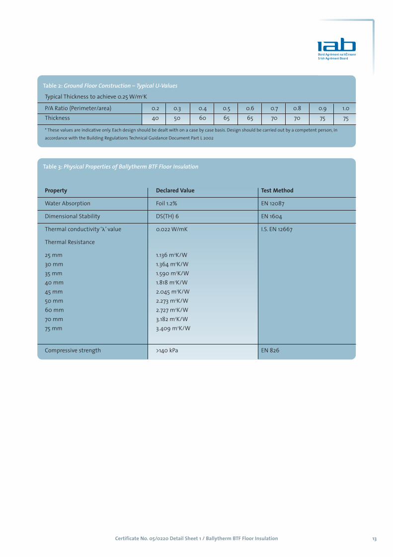
Table 2: Ground Floor Construction – Typical U-Values
Typical Thickness to achieve 0.25 W/m2K
P/A Ratio (Perimeter/area) 0.2 0.3 0.4 0.5 0.6 0.7 0.8 0.9 1.0
Thickness 40 50 60 65 65 70 70 75 75
* These values are indicative only. Each design should be dealt with on a case by case basis. Design should be carried out by a competent person, in
accordance with the Building Regulations Technical Guidance Document Part L 2002
Table 3: Physical Properties of Ballytherm BTF Floor Insulation
Property Declared Value Test Method
Water Absorption Foil 1.2% EN 12087
Dimensional Stability DS(TH) 6 EN 1604
Thermal conductivity ‘�’ value 0.022 W/mK I.S. EN 12667
Thermal Resistance
25 mm 1.136 m2K/W
30 mm 1.364 m2K/W
35 mm 1.590 m2K/W
40 mm 1.818 m2K/W
45 mm 2.045 m2K/W
50 mm 2.273 m2K/W
60 mm 2.727 m2K/W
70 mm 3.182 m2K/W
75 mm 3.409 m2K/W
Compressive strength >140 kPa EN 826

Certificate No. 05/0220 Detail Sheet 2 / Ballytherm BTCW Cavity Wall Insulation14
MANUFACTURE AND MARKETING:
The product is manufactured and marketed by:
Ballytherm Limited
Annagh Industrial Park, Ballyconnell
Co Cavan, Ireland
Tel: +353 (0) 49 9527000
Fax: +353 (0) 49 9527002
e-mail: [email protected]
Website: www.ballytherm.ie
Detail Sheet 2 / Ballytherm BTCW Rebated Cavity Wall Insulation
PRODUCT DESCRIPTION:
This Certificate relates to Ballytherm BTCW rebated cavity
wall insulation, as defined in IAB Certificate No. 05/0220.
USE:
Ballytherm BTCW cavity wall insulation is used for the
thermal insulation of new, cavity masonry walls of
dwellings or buildings of similar occupancy type and
conditions. It also facilitates the control of surface and
interstitial condensation in walls

Certificate No. 05/0220 Detail Sheet 2 / Ballytherm BTCW Cavity Wall Insulation 15
Part One / Technical Specification and Control Data 11.1 PRODUCT DESCRIPTION
This Certificate relates to Ballytherm BTCW cavity
wall insulation, a partial fill cavity wall board with a
rebated edge, using Polyisocyanurate (PIR) closed cell
rigid insulation manufactured in accordance with I.S.
EN 13165: 2001 Thermal insulation products forbuildings – Factory made products of polyurethanefoam (PUR) Specification. During the manufacturing
process, liquid raw materials expanded by blowing
agents are applied between low emissivity composite
foil facings. Ballytherm BTCW cavity wall insulation is
CFC and HCFC free.
This Certificate certifies compliance with the
requirements of the Building Regulations 1997 to 2002.
Table 1 shows the Ballytherm BTCW cavity wall
insulation, product range.
1.2 MANUFACTUREBallytherm BTCW cavity wall insulation is
manufactured from a formulation of chemicals,
which is poured onto low emissivity composite foil
facings subsequently autohesively bonded to the
insulation core during manufacture. The reflective,
low emissivity surface can increase the thermal
resistance of the residual cavity airspace in which the
board is placed.
1.3 INSTALLATION1.3.1 General
Walls are constructed in the conventional manner
with the first row of ties one course below damp-
proof course level at not greater than 600 mm
horizontal centres. Walls should be constructed in
accordance the relevant parts of I.S. 325- Use ofMasonry. It is recommended that the wall ties are not
placed directly on the damp-proof course. The first
row of insulation boards should be supported by the
ties providing edge insulation for the floor, as
required by Technical Guidance Document L –
Conservation of Fuel and Energy DWELLINGS (2002).
The mortar fill below d.p.c level must be considered
and it is also necessary to ensure that any installed
Radon Barrier is not damaged. The walls are
constructed by raising each section of the inner or
outer leaf up to the level of the next run of wall ties,
which are situated at a spacing shown in Table 2.
Ballytherm BTCW cavity wall insulation boards are
then placed in position behind the retaining clips of
the wall ties tight against the cavity face of the inner
leaf. The joints should be as neat as possible, assisted
by the rebated edge. This ensures maximum thermal
performance. It is recommended that drainage holes
be provided in the perpend block joints below d.p.c
level at approximately 1 m centres. Refer to I.S. 325:
Part 1 -Use of Masonry. Reference should also be made
to TGD- L (Dwellings), Clauses 0.6 and 1.5 and TGD- A
to the Building Regulations 1997 – 2002.
Each board should be secured by a minimum of 3
retaining clips. Additional wall ties at unbonded
openings, junctions and cut ends should be located at
a maximum 225 mm vertical centres and within 150
mm of any opening.
All wall ties should be installed correctly, clear of all
mortar, sloped downwards towards the outer leaf
and conform to structural design requirements. In
severe exposure zones Ballytherm BTCW cavity wall
insulation board should be installed in walls whilst
maintaining a 40 mm cavity width. Only certified
wall ties specified by Ballytherm Limited should be
used in conjunction with this system. Included in
each pack of ties is a small saw to cut the rebate of
the board for positioning of the tie at the required
spacing. The spacing of wall ties should be in
accordance with table 9a of I.S. 325: Part 2: 1995 Useof Masonry – Masonry Construction. Table 2 shows
typical wall tie spacing.
Successive sections of wall fixed by certified stainless
steel wall ties are constructed and Ballytherm BTCW
cavity wall insulation boards are installed as work
proceeds up to the required height. Excess mortar
should be removed and mortar droppings cleaned
from the exposed edges of the installed boards. Use
of cavity battens or cavity boards or similar means is
recommended to protect installed boards and keep
the cavity mortar free. Penetration of damp across
the cavity will be prevented with good practice.
Where the use of wall ties is inappropriate e.g. under
window cills, proprietary clips may be used to hold
the cavity boards tightly in place. Jamb details must
incorporate a vertical DPC, positioned between the
Ballytherm BTCW cavity wall insulation board and the
external leaf, returning a minimum of 150 mm.
Table 1: Product Range
The boards are available in the following sizes:
Length 2400m
Width 450mm (plus 10mm rebate)
Thickness 25, 30, 35, 40, 45, 50,
60, 70, and 75mm
Grade PIR
Certificate No. 05/0220 Detail Sheet 2 / Ballytherm BTCW Cavity Wall Insulation16
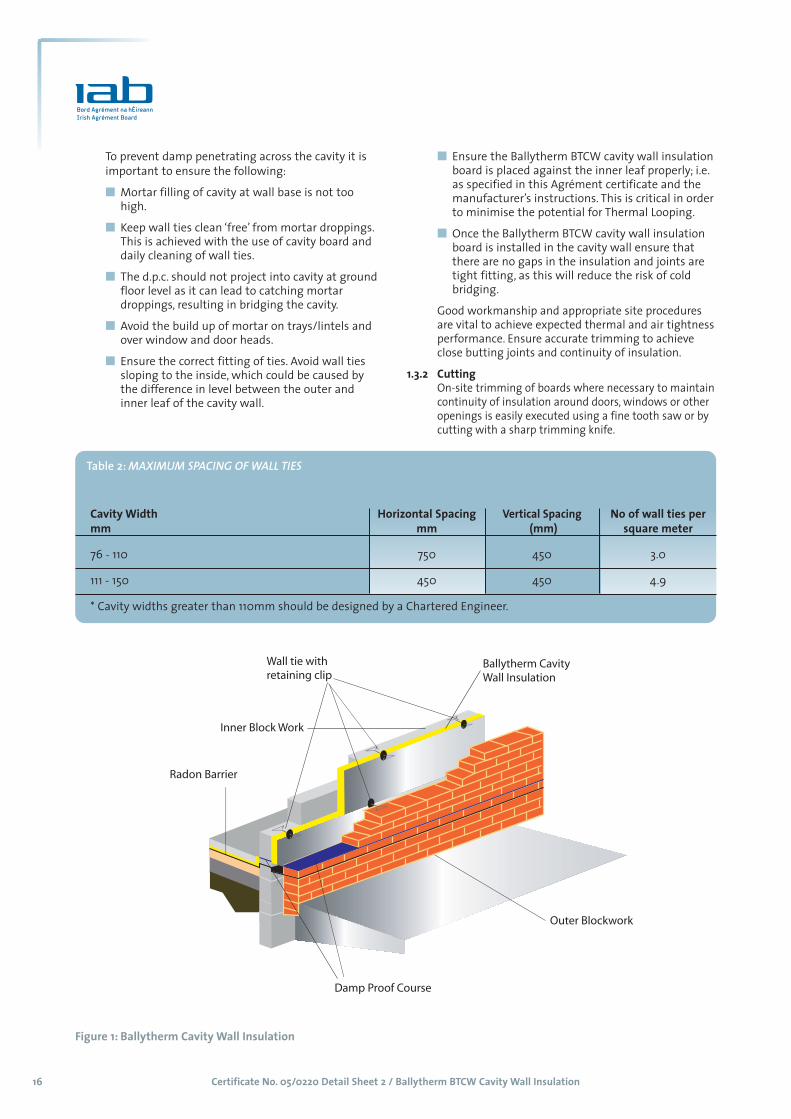
To prevent damp penetrating across the cavity it is
important to ensure the following:
■ Mortar filling of cavity at wall base is not too
high.
■ Keep wall ties clean ‘free’ from mortar droppings.
This is achieved with the use of cavity board and
daily cleaning of wall ties.
■ The d.p.c. should not project into cavity at ground
floor level as it can lead to catching mortar
droppings, resulting in bridging the cavity.
■ Avoid the build up of mortar on trays/lintels and
over window and door heads.
■ Ensure the correct fitting of ties. Avoid wall ties
sloping to the inside, which could be caused by
the difference in level between the outer and
inner leaf of the cavity wall.
■ Ensure the Ballytherm BTCW cavity wall insulation
board is placed against the inner leaf properly; i.e.
as specified in this Agrément certificate and the
manufacturer’s instructions. This is critical in order
to minimise the potential for Thermal Looping.
■ Once the Ballytherm BTCW cavity wall insulation
board is installed in the cavity wall ensure that
there are no gaps in the insulation and joints are
tight fitting, as this will reduce the risk of cold
bridging.
Good workmanship and appropriate site procedures
are vital to achieve expected thermal and air tightness
performance. Ensure accurate trimming to achieve
close butting joints and continuity of insulation.
1.3.2 CuttingOn-site trimming of boards where necessary to maintain
continuity of insulation around doors, windows or other
openings is easily executed using a fine tooth saw or by
cutting with a sharp trimming knife.
image
Figure 1: Ballytherm Cavity Wall Insulation
Table 2: MAXIMUM SPACING OF WALL TIES
Cavity Width Horizontal Spacing Vertical Spacing No of wall ties per mm mm (mm) square meter
76 - 110 750 450 3.0
111 - 150 450 450 4.9
* Cavity widths greater than 110mm should be designed by a Chartered Engineer.

Certificate No. 05/0220 Detail Sheet 2 / Ballytherm BTCW Cavity Wall Insulation 17
2 GENERAL2.1 Ballytherm BTCW cavity wall insulation board when
installed in accordance with this Certificate, is
effective in reducing the 'U' value (thermal
transmittance) of new external masonry cavity walls,
using clay or calcium silicate bricks, concrete blocks,
or natural and reconstituted stone blocks. It is
essential that such walls are designed and
constructed to prevent moisture penetration having
regard to the Driving Rain Index.
2.2 External Walls of buildings subject to the relevant
requirements of the Building Regulations 1997 - 2002
should be constructed in accordance with I.S. 325: Part
1: 1986 Use of Masonry, Structural Use of Unreinforced
Masonry, and BS 5628: Part 3: 1995 Code of Practice for
use of Masonry: Materials and Components, Design
and Workmanship. Where reinforced masonry is
involved, the design should be in accordance with BS
5628: Part 2: 1985, Code of Practice for use of Masonry,
Structural Use of Reinforced and Prestressed Masonry.
The relevant recommendations of Section 3 of BS
5390: 1976 (1984), Code of Practice for Stone Masonry,
should be followed where the wall incorporates stone
or cast stone.
2.3 The use of a cavity board or cavity batten during
construction is recommended to prevent
accumulation of mortar droppings on the top edge of
the Ballytherm BTCW cavity wall insulation board and
to prevent bridging of cavity by mortar droppings.
2.4 As with all cavity wall insulation, the construction
detailing should comply with good practice. (see also
reference to installation in paragraph 1.3).
2.5 It is recommended that installation be carried out to
the highest level on each wall. Where appropriate the
top edge of the insulation should be protected by a
cavity tray. On site trimming of boards may be
necessary to achieve this.
2.6 Where a nominal residual cavity width of at least 40
mm is maintained, Ballytherm BTCW cavity wall
insulation board is suitable for use in any exposure
conditions, in buildings up to 12 meters in height. See
I.S. 325 Part 2: 1995 Masonry Construction, for
information on the Exclusion of Moisture (Driving Rain)
It is important to ensure during installation that:
a) Wall ties and fixings are installed correctly and are
thoroughly clean.
b) Excess mortar is cleaned from the inside face of
the leading leaf and any debris is removed from
the cavity.
c) Mortar droppings are cleaned from the exposed
edges of installed slabs.
2.7 Data obtained by the IAB confirms that a masonry
wall incorporating the Ballytherm BTCW cavity wall
insulation board and built to the requirements of I.S.
325: Part 1: 1986, Use of Masonry, Part 1: Structural Use
of Unreinforced Masonry will not transmit water to
the inner leaf.
2.8 Data obtained by the IAB also demonstrates that
Ballytherm BTCW cavity wall insulation boards do not
absorb water by capillary action. When the product is
used in situations where it bridges the dpc in walls,
dampness from the ground will not pass through,
provided the cavity is taken down to at least 150 mm
below the level of the lowest dpc.
2.9 A minimum cavity width of at least 40 mm should be
maintained where possible. Where, for structural
reasons, the cavity width is reduced by the intrusion
of ring beams or other structural elements, the
manufacturer's advice on fixing and weather-
proofing should be sought. Raked or recessed mortar
joints are not suitable in high exposure areas and
must be avoided.
Part Two / Design Data 2

Certificate No. 05/0220 Detail Sheet 2 / Ballytherm BTCW Cavity Wall Insulation18
3.1 BEHAVIOUR IN FIRE3.1.1 General
(i) Ballytherm BTCW cavity wall insulation board
may be used in buildings of any purpose group in
a wall in which the cavity intercommunicates
with another such cavity, and may be unlimited
in extent in respect of the provision of barriers
provided the walls comply with Part B3, Diagram
17 of TGD B to the Building Regulations 1997 -
2002, (Cavity walls excluded from provisions for
cavity barriers) as follows: -
(ii) a) The wall consists of two leaves, each being not
less than 75 mm thick and constructed of non-
combustible materials;
b) The cavity does not exceed 110 mm in width
and is closed by a cavity barrier at the top of the
wall and at the top of any opening through any
leaf of the wall; and
c) There is no combustible material exposed or
situated within the cavity other than:
(i) timber lintels, window or door frames or
the end faces of joists.
(ii) pipes, ducts or cables.
(iii) closers, flashings, damp proof courses or
wall ties.
(iv) thermal insulating material or
(v) meter boxes which require an opening in
the outer leaf of not greater than 800 mm
x 500 mm and do not penetrate the inner
leaf except through a sleeve of not more
than 80 mm by 80 mm which is fire
stopped where it passes through the inner
leaf.
(iii) Spread of flame within the cavity - Ballytherm
BTCW cavity wall insulation board is designated
Class 1 in accordance with BS 476: Part 7: 1997. In
an unventilated cavity the amount of air will be
insufficient to support combustion and flame
spread is unlikely to occur.
(iv) Toxicity - Negligible when used in a cavity wall
situation.
(v) Ballytherm BTCW cavity wall insulation board is
manufactured without the use of CFC’s or HCFC’s,
there is no release of such gas on burning.
3.1.2 J3 Protection of Building - Combustible wall insulation material shall generally
be separated by solid non-combustible material not
less than 200 mm thick, from any heating appliance
or from any flue pipe or opening to a heating
appliance. Particular details are given in Section 2,
and in Diagrams 2 - 8 of the TGD J to the Building
Regulations 1997 - 2002. It should also be separated
by 40 mm from the external surface of a masonry
chimney. For chimneys covered by BS 4543 Part 1:
1990 (1996) ‘Factory made insulated chimneys’
separation between this product and the external
surface of the chimney shall be determined in
accordance with clause 2.17, of TGD – J to the
Building Regulations 1997 - 2002.
3.2 WATER PENETRATION3.2.1 Capillary Action - The closed cell structure does not
allow water uptake by capillary action.
3.2.2 Ballytherm BTCW cavity wall insulation board, when
used in accordance with this Certificate, presents no
significant risk of water penetration.
3.3 WATER VAPOUR PENETRATION ANDCONDENSATION RISKBallytherm BTCW cavity wall insulation board has an
integral vapour check and has a significant resistance
to the passage of water vapour, when used in
conventional masonry cavity wall construction. This
obviates the risk of surface condensation and
presents no significant risk of damage from
interstitial condensation. Correct use of the heating
and ventilation system is important. When insulating
buildings the recommendations of BS 5250: 2002
Code of practice for control of condensation in buildings,
should be followed to minimise the risk of condensation
within the building elements and structures.
3.4 THERMAL INSULATIONThe aged/design thermal conductivity ‘�’ value' of
Ballytherm BTCW cavity wall insulation boards when
measured in accordance with I.S. EN 12667: 2000
Thermal performance of building materials and
products – Determination of thermal resistance by
means of guarded hot plate and heat flow meters
method – Products of high and medium thermal
resistance, is 0.022 W/mK. The high thermal
resistance of Ballytherm BTCW cavity wall insulation
board ensures that cold bridging and extra heat loss
around the edges of openings can be avoided.
Uncontrolled leakage of air through the fabric of a
building and/or cracks in and around door and
window frames, sills, jambs etc. air movement due to
thermal effects or due to wind pressure can occur.
Details of how to avoid the infiltration of cold air are
given in TGD – L (DWELLINGS), Section 1.6.
Lintel jamb and cill designs similar to those shown in
Diagram 3 of the TGD to Part L (DWELLINGS), Building
Regulations 1997 - 2002, will be satisfactory to limit
thermal bridging.
Part Three / Technical Investigations 3
Certificate No. 05/0220 Detail Sheet 2 / Ballytherm BTCW Cavity Wall Insulation 19
The maximum U-values for external walls using
Ballytherm BTCW cavity wall insulation board
constructions can be determined by reference to
Appendix A of TGD –L Conservation of Fuel and Energyto Building Regulations 2002. The aged/design
thermal conductivity ‘�’ value' of Ballytherm
BTCW cavity wall insulation board is 0.022 W/mK.
See Table 3 for wall construction to achieve a
U-value of 0.27W/m2K.
3.5 DURABILITYBallytherm BTCW cavity wall insulation board is
judged to be stable and will remain effective as an
insulation system for the life of the building, so long
as it is installed in accordance with this certificate. Its
durability depends upon the supporting structure
and the conditions of use.
3.6 TESTS AND ASSESSMENTS WERE CARRIED OUT TODETERMINE THE FOLLOWING:■ density
■ water vapour permeability
■ water uptake
■ dimensional accuracy
■ compressive and cross breaking strength
■ dimensional stability
■ thermal conductivity
■ efficiency of the construction process
3.7 Electrical installations should be in accordance with
the ETCI publication ET 207: 2003 Guide to theNational Rules for Electrical Installations as Applicableto Domestic Installations. It is recommended that
cables should not be buried in the insulation and
carried in a conduit. In relation to recessed spotlights
and other luminaries, ET 207 requires they be not less
than the minimum distances from combustible
materials as specified in clause 559.3.2 of the TCI
National rules of the Electro Technical Council of
Ireland (ET 101).
3.8 RESISTANCE TO SOLVENTS, FUNGI AND RODENTSBallytherm BTCW cavity wall insulation board referred
to in this certificate do not promote infestation, as
there is no food value in the materials used. They also
resist attack by mould and microbial growth. The
insulation is not resistant to some solvent-based
adhesive systems, particularly those containing
methyl ethyl keytone. Adhesives containing such
solvents should not be used in association with the
boards. The insulation core is however resistant to
dilute acids, alkalis, mineral oil and petrol.
Boards which have been in contact with harsh solvents,
petrol, mineral oil or acids or boards that have been
damaged in any other way should not be used.
3.9 OTHER INVESTIGATIONS(i) Existing data on product properties in relation to
fire, toxicity, environmental impact and the effect
on mechanical strength/stability and durability
were assessed. Ballytherm BTCW cavity wall
insulation board does not contain CFC or HCFC gas.
(ii) The manufacturing process was examined
including the methods adopted for quality
control, and details were obtained of the quality
and composition of the materials used.
(iii) Site visits were conducted to assess the
practicability of installation and the history of
performance in use of the product.
(iv) A condensation risk analysis was performed.
Certificate No. 05/0220 Detail Sheet 2 / Ballytherm BTCW Cavity Wall Insulation20
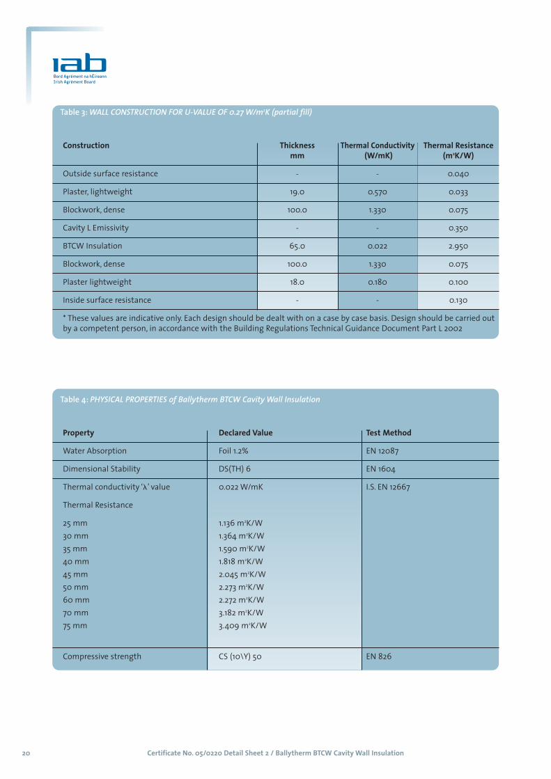
Table 4: PHYSICAL PROPERTIES of Ballytherm BTCW Cavity Wall Insulation
Property Declared Value Test Method
Water Absorption Foil 1.2% EN 12087
Dimensional Stability DS(TH) 6 EN 1604
Thermal conductivity ‘�’ value 0.022 W/mK I.S. EN 12667
Thermal Resistance
25 mm 1.136 m2K/W
30 mm 1.364 m2K/W
35 mm 1.590 m2K/W
40 mm 1.818 m2K/W
45 mm 2.045 m2K/W
50 mm 2.273 m2K/W
60 mm 2.272 m2K/W
70 mm 3.182 m2K/W
75 mm 3.409 m2K/W
Compressive strength CS (10\Y) 50 EN 826
Table 3: WALL CONSTRUCTION FOR U-VALUE OF 0.27 W/m2K (partial fill)
Construction Thickness Thermal Conductivity Thermal Resistancemm (W/mK) (m2K/W)
Outside surface resistance - - 0.040
Plaster, lightweight 19.0 0.570 0.033
Blockwork, dense 100.0 1.330 0.075
Cavity L Emissivity - - 0.350
BTCW Insulation 65.0 0.022 2.950
Blockwork, dense 100.0 1.330 0.075
Plaster lightweight 18.0 0.180 0.100
Inside surface resistance - - 0.130
* These values are indicative only. Each design should be dealt with on a case by case basis. Design should be carried out
by a competent person, in accordance with the Building Regulations Technical Guidance Document Part L 2002

Certificate No. 05/0220 Detail Sheet 3 / Ballytherm BTDL Dry Lining 21
MANUFACTURE AND MARKETING:
The product is manufactured and marketed by:
Ballytherm Limited
Annagh Industrial Park, Ballyconnell
Co Cavan, Ireland
Tel: +353 (0) 49 9527000
Fax: +353 (0) 49 9527002
e-mail: [email protected]
Website: www.ballytherm.ie
Detail Sheet 3 / Ballytherm BTDL Dry Lining Board Insulation
PRODUCT DESCRIPTION:
This Certificate relates to Ballytherm BTDL dry lining, as
defined in IAB Certificate No 05/0220
USE:
Ballytherm BTDL dry lining is used for the thermal insulation
of existing or new, solid or cavity masonry walls of dwellings
or buildings of similar occupancy type and conditions. It may
also be used to line ceilings. It also facilitates the control of
surface and interstitial condensation in walls and ceilings.

Certificate No. 05/0220 Detail Sheet 3 / Ballytherm BTDL Dry Lining 22
1.1 PRODUCT DESCRIPTIONBallytherm BTDL Dry Lining is a composite panel
consisting of a closed cell rigid Polyisocyanurate (PIR)
insulation bonded to tapered edge plasterboard for
internal applications. The plasterboard is 12.5 mm
thick manufactured to BS 1230 – Gypsum
plasterboard, and accepts dry-jointing materials,
plaster skim or direct decoration. Ballytherm BTDF Dry
lining has Kraft paper with a polythene membrane on
both faces, which acts as an integral vapour check.
Polyisocyanurate (PIR) foam core is a thermoset closed
cell rigid foam insulation manufactured in accordance
with I.S. EN 13165: 2001 Thermal insulation products forbuildings – Factory made products of polyurethanefoam (PUR) Specification.
Ballytherm BTDL Dry Lining board does not contain
either CFC or HCFC gases and has zero Ozone
Depletion Potential (ODP).
Table 1 shows the Ballytherm BTDL Dry Lining,
product range.
1.2 MANUFACTUREBallytherm BTDL Dry Lining is manufactured from a
formulation of chemicals, which is sprayed onto the
kraft paper facer and subsequently plasterboard is
adhesive bonded to the insulation core. The
plasterboard face provides a durable surface to
accept traditional finishing techniques.
1.3 INSTALLATION PROCEDURE 1.3.1 Ballytherm BTDL Dry Lining board is for installation
on the internal surface of walls and ceilings of new or
existing buildings. The fixing method depends on the
substrate.
Installation should be in accordance with good
drylining practice and the manufacturer’s
instructions. All installations require careful planning
and setting out. Refer to clauses 0.6 and 1.5 of TGD
Part-L to Building Regulations 2002.
Before fixing the product, sufficient time must be
allowed to disperse the solvents contained in wood
preservatives and damp proofing treatments where
applied.
Ceiling plaster slabs should be fixed in place before
dry lining commences.
1.3.2 Systems and Fixings
Thermal Bridging Walls should be insulated to full height and returned
at door/window reveals to prevent cold bridging. The
margins of window and door reveals should be
sufficient to accommodate the thickness of
Ballytherm BTDL Dry Lining board being employed.
The possibility of a cold bridge occurring via the
window boards should also be considered and
provision made to insulate this area. Services should
be fixed in place before drylining commences. The
void between the wall and the Thermal Liner can
accommodate certain services however the PIR
insulation should not be chased. The area around any
services that penetrate the Thermal Liner must be
sealed to prevent air leakage and thermal looping.
Thermal Looping/Fire StopsWhen required fire stops must be provided using
proprietary methods or by applying a continuous 50
mm ribbon of dry wall adhesive to the top and
bottom edge of each sheet. A treated timber batten
will also suffice.
Adhesive Bonding This method is for application to sound, plane
concrete or plastered wall surfaces on cavity walls.
Adhesive is applied to the wall surface in strips to a
pre-determined pattern that coincides with the
edges of the board; a further strip is applied
horizontally at the mid point of the board. Suitable
approved mechanical fixings are recommended to
complement the adhesive bond, these are normally
applied at a rate of 3 No. per board, after the adhesive
has set. Two fixings positioned at the top of each
board and one at the board centre. Allow for
expansion at the top and bottom of the panel. The
certificate holder’s advice should be sought in
relation to the type of adhesive and the choice of
fixings.
Mechanical FixingThis method is for application to fair finished brick,
block and concrete cavity walls where Ballytherm BTDL
Dry Lining board is to be finished with gypsum plaster.
The wall should be sound, dry and level. (Surface
irregularities may impede the fixing of the board).
Part One / Technical Specification and Control Data 1
Table 1: Product Range
The boards are available in the following sizes:
Length 2400m
Width 1200mm
Thickness 20, 25, 30, 35, 40, 45, 50, 60, 70,
and 80mm
Grade PIR
Certificate No. 05/0220 Detail Sheet 3 / Ballytherm BTDL Dry Lining 23
The board should be fully restrained using
mechanical fixings. There should be 18 No. fixings per
2400 x 1200 board, three of which should be type TID
– M anchors. Other fixings should be in accordance
with the fixing supplier’s recommendations, and
should be evenly distributed over the whole area of
the board. Fixings should not overlap board’s edges
and should penetrate at least 30mm into the
masonry.
Linings (Horizontal and sloping)Ballytherm BTDL Dry Lining board may be used to line
ceilings. Insulation is fixed in a similar way to
standard plasterboard. Boards must always be placed
with the long edge running across the joists, rafters
or battens and all edges must be supported. Timbers
must offer a minimum 20 mm support to all four
edges of the board. This will necessitate the use of
noggins placed between the joists to coincide with
the long edges of the board. Large headed galvanised
clout or sheradised nails should be used to fix the
board. These must be long enough to allow a
minimum 25 mm penetration of the supporting
timber, and be placed not less than 10 mm from the
edges of the board and be spaced at 150 mm
intervals along all supporting timbers.
1.3.3 CuttingOn-site cutting of boards where it is necessary to
maintain continuity of insulation around doors,
windows or other openings is easily executed using a
fine tooth saw or by cutting through the insulation.
Cutting BTDL panels is also easy to execute by using
a trimming knife to cut through the insulation and
paper backing of the plasterboard layer, then
snapping the board face down over a straight edge
and cutting the paper facing of the plasterboard on
the other side.
Good workmanship and appropriate site procedures
are necessary to achieve expected thermal and air
tightness performance. Ensure accurate trimming to
achieve close butting joints and continuity of
insulation.
1.3.4 Finishing Tapered edged boards are jointed and finished in
accordance with standard dry lining procedure offering
a surface suitable for paper hanging and paint finishes.
A plaster skim finish can also be applied to the boards.
The finishing should be carried out in accordance with
the specified manufacturer’s instructions, particularly
in relation to the need to allow thorough drying of the
plaster prior to decoration.
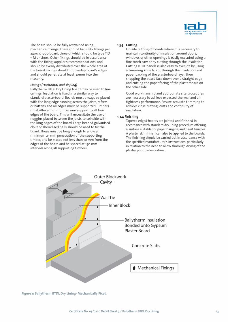
Figure 1: Ballytherm BTDL Dry Lining- Mechanically Fixed.

Certificate No. 05/0220 Detail Sheet 3 / Ballytherm BTDL Dry Lining 24
2 GENERAL2.1 Ballytherm BTDL Dry Lining board when installed in
accordance with this Certificate, is effective in
reducing the 'U' value (thermal transmittance) of
new or existing walls and ceilings.
Ballytherm BTDL Dry Lining board may be used to
insulate clay or calcium silicate bricks, concrete
blocks, or natural and reconstituted stone blocks. It is
essential that such walls are designed and
constructed to prevent moisture penetration having
regard to the Driving Rain Index.
2.2 Buildings subject to the relevant requirements of the
Building Regulations 1997 to 2002 should be
constructed in accordance with I.S. 325: Part 1: 1986
Use of Masonry, Part 1: Structural Use of Unreinforced
Masonry, and BS 5628: Part 3: 1995 Code of Practice for
use of Masonry: Materials and Components, Design
and Workmanship. Particular attention should be paid
to the exclusion of moisture in that the designer
should select a construction appropriate to the local
wind driven rain index, paying due regard to the
design detailing, workmanship and materials to be
used. Where reinforced masonry is involved, the
design should be in accordance with BS 5628: Part 2:
1985, Code of Practice for use of Masonry, Structural
Use of Reinforced and Prestressed Masonry. The
relevant recommendations of Section 3 of BS 5390:
1976 (1984), Code of Practice for Stone Masonry,
should be followed where the wall incorporates stone
or cast stone.
2.3 With dry lining installations forming a void of 20 mm
or more, services can be incorporated behind the dry
lining, making the chasing of the wall unnecessary.
When using adhesive systems, or where the services
have a greater depth than the void, the wall should
be chased rather than the insulation.
2.4 All mould or fungal growth should be treated prior
to the application of the product.
2.5 When bonding is by adhesives, it is essential that a
satisfactory bond is achieved between the walling
material and the adhesives. Backgrounds of high
suction will behave differently to those of low
suction. The Certificate holder’s advice should be
sought in case of difficulty.
Part Two / Design Data 2

Certificate No. 05/0220 Detail Sheet 3 / Ballytherm BTDL Dry Lining 25
3.1 BEHAVIOUR IN FIREThe plasterboard used in the Ballytherm BTDL Dry
Lining board is deemed to be Class ‘O’ in accordance
with the Building Regulations, 1997 – 2002 and so the
insulated board qualifies as the highest product
performance classification as defined in Technical
Guidance Document B - Fire Safety (paragraph A10 of
Annex A). The insulation component of the board
should be isolated from possible sources of
combustion. To achieve this Ballytherm BTDL Dry
Lining board should be installed in accordance with
the following: -
(i) Combustible material shall be separated by solid
non-combustible material not less than 200 mm
thick from a flue pipe to an oil, solid fuel or gas
heating appliance as indicated in Section 2 of
Technical Guidance Document J – Heat
Producing Appliances.
(ii) Ballytherm BTDL Dry Lining board should be
separated by a minimum distance of 150 mm
from an oil, solid fuel or gas heating appliance as
indicated in Diagram 8 of Technical Guidance
Document J - Heat Producing Appliances, of
Building Regulations 1997.
(iii) Ballytherm BTDL Dry Lining board when installed
with a residual cavity between the board and the
wall, will require the provision of cavity barriers
and may be used in buildings of any purpose
group provided: -
(a) direction on the provision and spacing of
cavity barriers is given in Tables 3.2 and 3.3 of
Technical Guidance Document B – Fire Safety to
the Building Regulations.
(b) every such cavity shall be closed by a cavity
barrier around the whole perimeter of the wall
or ceiling element and around the perimeter of
any opening through such elements; and
(c) cavity barriers in spaces between a floor and
ceiling are provided at maximum distances of
20 m for any class of surface exposed to the cavity.
(d) where any wall or ceiling containing a cavity
meets another such element, the cavities shall be
closed so that they do not communicate with
one another.
(e) cavity barriers in walls are provided at
maximum distances apart of 10 m unless a Class
1 material is exposed to the cavity when a
spacing of 20 m may be adopted.
3.2 WATER PENETRATION3.2.1 Ballytherm BTDL Dry Lining board closed cell structure
does not allow water uptake by capillary action.
3.2.2 Ballytherm BTDL Dry Lining board, when used in
accordance with this Certificate, presents no significant
risk of water penetration.
3.3 THERMAL INSULATIONThe aged/design thermal conductivity ‘�’ value of
Ballytherm BTDL Dry Lining board when measured in
accordance with I.S. EN 12667: 2000 Thermal
performance of building materials and products –
Determination of thermal resistance by means of
guarded hot plate and heat flow meters method –
Products of high and medium thermal resistance, is
0.026 W/mK. The high thermal resistance of Ballytherm
BTDL Dry Lining board ensures that cold bridging and
extra heat loss around the edges of openings can be
avoided. Refer to Appendix A of Technical Guidance
Document L to Building Regulations 2002.
Lintel jamb and cill designs similar to those shown in
Diagram 3 of the TGD to Part L – Conservation of Fuel
and Energy DWELLINGS, (Building Regulations 2002),
will be satisfactory to limit thermal bridging.
Uncontrolled leakage of air through the fabric of a
building and/or cracks in and around door and window
frames, sills, jambs etc. can occur due to wind pressure
or air movement due to thermal effects. Details of how
to avoid the infiltration of cold air are given in Section
1.6 of TGD Part L (DWELLINGS), to the Building
Regulations 2002.
The maximum U-values which can be achieved with
Ballytherm BDTL dry lining should be determined in
accordance with the procedures of Appendix A, clauses
A3.1- A3.3 of Technical Guidance Document L to Building
Regulations 2002.
3.4 MATERIALS IN CONTACT WITH ELECTRICAL WIRINGElectrical installations should be in accordance with the
ETCI publication ET 207: 2003 Guide to the NationalRules for Electrical Installations as Applicable to DomesticInstallations. It is recommended that cables should not
be buried in the insulation and carried in a conduit. In
relation to recessed spotlights and other luminaries, ET
207 requires they be not less than the minimum
distances from combustible materials as specified in
clause 559.3.2 of the TCI National rules of the Electro
Technical Council of Ireland (ET 101).
For extra low voltage (ELV) it is recommended that only
surface mounted ELV lighting be permitted in
conjunction with Ballytherm BTDL Dry Lining Board.
Part Three / Technical Investigations 3
Certificate No. 05/0220 Detail Sheet 3 / Ballytherm BTDL Dry Lining 26
3.5 CONDENSATION RISKBallytherm BTDF Dry lining has Kraft paper with a
polythene membrane on both faces, which acts as an
integral vapour check. It is therefore unlikely to be
affected by surface or interstitial condensation,
provided the correct thickness of Ballytherm BTDL Dry
Lining board is chosen and all joints between boards are
filled and taped in accordance with Standards Dry Lining
practice. Correct use of the heating and ventilation
system is important. Interstitial condensation analysis
for average winter environmental conditions for cavity
wall constructions indicate no condensation risk. When
insulating buildings the recommendations of BS 5250:
2002 Code of practice for control of condensation in
buildings, should be followed to minimise the risk of
condensation within the building elements and structures.
3.6 RESITANCE TO SOLVENTS, FUNGI AND RODENTSBallytherm BTDL Dry Lining board panels do not
promote infestation, as there is no food value in the
materials used. They also resist attack by mould and
microbial growth. The insulation core is resistant to
dilute acids, alkalis, mineral oil and petrol. It is not
resistant to some solvent-based adhesive systems,
particularly those containing methyl ethyl keytone.
Adhesives containing such solvents should not be used
in association with the boards. Boards which have been
in contact with harsh solvents, petrol, mineral oil or
acids or boards that have been damaged in any other
way should not be used.
3.7 WALL MOUNTED FITTINGSThe recommendations of the manufacturer should be
followed. Any object fixed to the wall, other than
lightweight items, e.g. framed pictures, should be fixed
through the lining board into the wall behind, using
proprietary fixings.
3.8 MAINTENANCEDamaged boards can be easily replaced and no
maintenance of the insulation will be required provided
that the plasterboard layer remains intact.
3.9 DURABILITYBallytherm BTDL Dry Lining board is judged to be stable
and will remain effective as an insulation system for the
life of the building, so long as it is installed in accordance
with this certificate. Its durability depends upon the
supporting structure and the conditions of use.
3.10 LIMITATIONS Ballytherm BTDL Dry Lining board has a gypsum
plasterboard face, it should therefore not be used to
isolate dampness nor be used in continuously damp or
humid conditions.
3.11 OTHER INVESTIGATIONS(i) Existing data on product properties in relation to
fire, toxicity, environmental impact and the effect
on mechanical strength/stability and durability
were assessed. Ballytherm BTDL Dry Lining board
does not contain CFC or HCFC gas.
(ii) The manufacturing process was examined
including the methods adopted for quality control,
and details were obtained of the quality and
composition of the materials used.
(iii) Site visits were conducted to assess the
practicability of installation and the history of
performance in use of the product.
(iv) A condensation risk analysis was performed.

Certificate No. 05/0220 Detail Sheet 3 / Ballytherm BTDL Dry Lining 27
Table 2: PHYSICAL PROPERTIES of Ballytherm BTDL Dry Lining Board
Property Declared Value Test Method
Water Absorption Foil 1.2% EN 12087
Kraft Paper 2.1%
Dimensional Stability DS(TH) 6 EN 1604
Thermal conductivity ‘�’ value 0.026 W/mK I.S. EN 12667
Thermal Resistance
20 mm 0.769 m2K/W
25 mm 0.962 m2K/W
30 mm 1.154 m2K/W
35 mm 1.346 m2K/W
40 mm 1.538 m2K/W
45 mm 1.731 m2K/W
50 mm 1.923 m2K/W
60 mm 2.308 m2K/W
70 mm 2.692 m2K/W
75 mm 2.885 m2K/W
Compressive strength Foil: CS (10\Y)50 EN 826
Kraft Paper: CS (10Y)100

Certificate No.05/0220 Detail Sheet 4 / Ballytherm BTR Pitch Roof Insulation28
MANUFACTURE AND MARKETING:
The product is manufactured and marketed by:
Ballytherm Limited
Annagh Industrial Park, Ballyconnell
Co Cavan, Ireland
Tel: +353 (0) 49 9527000
Fax: +353 (0) 49 9527002
e-mail: [email protected]
Website: www.ballytherm.ie
Detail Sheet 4 / Ballytherm BTR Pitch Roof Insulation
PRODUCT DESCRIPTION:
This Certificate relates to Ballytherm BTR Pitch Roof
Insulation, as defined in IAB Certificate No. 05/0220.
USE:
The product is used for the thermal insulation of pitched
and tiled roofs constructed in accordance with I. S. ICP 2:
2002 - Code of Practice for Slating and Tiling, 2002. It can
be used between, or between and under rafters. It also
facilitates the control of surface and interstitial
condensation in roofs.
Certificate No. 05/0220 Detail Sheet 4 / Ballytherm BTR Pitch Roof Insulation 29
1.1 PRODUCT DESCRIPTIONThis Certificate relates to the Ballytherm BTR Pitch
Roof Insulation using Polyisocyanurate (PIR), closed
cell rigid foam insulation with an integral vapour
barrier, manufactured in accordance with I.S. EN
13165: 2001 Thermal insulation products for buildings –Factory made products of polyurethane foam (PUR)Specification. During the manufacturing process,
liquid raw materials expanded by blowing agents are
applied between low emissivity composite foil
facings. Ballytherm BTR Pitch Roof Insulation boards
are CFC and HCFC free and therefore have zero ozone
depletion potential (zero ODP).
This Certificate certifies compliance with the
requirements of the Building Regulations 1997 to 2002.
Table 1 shows the Ballytherm BTR Roof insulation,
product range.
1.2 MANUFACTUREBallytherm BTR Pitch Roof Insulationis manufactured
from a formulation of chemicals, which is sprayed
onto composite foil facings subsequently
autohesively bonded to the insulation core during
manufacture.
1.3 INSTALLATION PROCEDURE 1.3.1 General
Installation must be in accordance with the relevant
clauses of I. S. ICP 2: 2002 - Code of Practice for
Slating and Tiling and the manufacturers instructions
and can be carried out in all conditions normal for
roof construction. Refer also to clause 0.6 (Technical
Risks and Precautions - General) and Appendix A of
Technical Guidance Document L to the Building
Regulations 2002.
Ballytherm BTR Pitch Roof Insulation is light to
handle and can be easily cut or shaped. The boards
will not support the weight of operatives and care
must be taken during tiling as indicated in the
Company’s Safety Notes.
Where the board is installed in Traditional and Timber
Frame Construction cavity barriers at the junction of
the external wall and roof space should be provided
in accordance with the requirements of Part B of the
Building Regulations 1997 - 2002.
1.3.2 Procedure – Between Rafter Layer of Insulation (Cold Roof)Ballytherm BTR Pitch Roof Insulation may be used in
pitched roof constructions where the insulation
follows the slope of the roof. Battens fixed to the
rafters may be used as a retaining stop. The required
thickness of Ballytherm BTR Pitch Roof Insulation is
fixed between the rafters to achieve the relevant ‘U
value’. However, where the requirement is for very
low ‘U values’ or to reduce the effects of thermal
bridging, a second layer fixed to the underside of the
rafters over the first layer may be appropriate. As in
the solution for the Warm Roof when the relevant
space is to be used as a living area, Ballytherm BTR
Pitch Roof Insulation should be covered with 12.5mm
plasterboard or use Ballytherm BTDL Dry Lining
board, which eliminates the cold bridge effect of the
rafters.
A vapour control layer should be installed between
the plasterboard and BTR insulation or between the
BTDL Dry Lining Board and BTR Insulation. In cases
where the insulation between rafters is to be flush
with the top of the rafters but does not fill the full
rafter depth, the insulation can be installed by the
use of proprietary nailable sarking clips. The nailable
sarking clips are driven into the upper surface of each
of rafter at one-metre intervals up the roof slope. The
nailable sarking clips then support lengths of
Ballytherm BTR Pitch Roof Insulation suitably
trimmed to size and placed between the rafters.
In cases where the Ballytherm BTR Pitch Roof
Insulation between the rafters is to be flush with the
bottom of the rafters but does not fill the full rafter
depth, install the insulation with the aid of battens
nailed to the side of the rafters. The battens should
be in the appropriate position to ensure the
insulation flush with the bottom of the rafters.
In cases where the Ballytherm BTR Pitch Roof Insulation
between rafters fully fills the rafter depth, simply install
the correct thickness of insulation in such manner that
it is flush with the bottom of the rafters.
In accordance with building regulations, a 50 mm
ventilation space should be maintained between the
sarking felt and the insulation in “Cold Roof”
construction, unless a breather membrane is used
allowing for a reduction in the recommended
airspace. (Refer to manufacturers instruction and
conditions of the certificate).
Part One / Technical Specification and Control Data 1
Table 1: Product Range
The boards are available in the following sizes:
Length 2400m
Width 1200mm
Thickness 25, 30, 35, 40, 45, 50, 55, 60, 65,
70, and 75mm
Grade PIR

Certificate No. 05/0220 Detail Sheet 4 / Ballytherm BTR Pitch Roof Insulation30
1.3.3 CuttingOn-site cutting of boards where it is necessary to
maintain continuity of insulation around doors,
windows or other openings is easily executed using a
fine tooth saw or by cutting through the insulation.
Cutting BTR panels is also easy to execute by using a
trimming knife to cut through the insulation and
paper backing of the plasterboard layer, then
snapping the board face down over a straight edge
and cutting the paper facing of the plasterboard on
the other side.
Good workmanship and appropriate site procedures
are necessary to achieve expected thermal and air
tightness performance. Ensure accurate trimming to
achieve close butting joints and continuity of
insulation.
1.3.4 Breather membranesBreather membrane for the purposes of this Agrement
Certificate should be approved for use with the system
by Ballytherm Limited or may be any other breather
membrane with an Irish Agrement Certificate.
1.3.5 Slating and tilingSlating and tiling is installed in accordance with I. S.
ICP 2: 2002 - Code of Practice for Slating and Tiling.
When the relevant space is to be used as a living area,
Ballytherm BTR Pitch Roof Insulation should be
covered with 12.5 mm plasterboard or Ballytherm BTDL
Dry Lining board. A vapour control layer should be
fixed as described in section 1.3.2 of this Detail Sheet.
image
Figure 1: Ballytherm BTR Pitch Roof Insulation
Certificate No. 05/0220 Detail Sheet 4 / Ballytherm BTR Pitch Roof Insulation 31
2 GENERAL2.1 Ballytherm BTR Pitch Roof Insulation when installed
in accordance with this Certificate is effective in
reducing the ‘U’ value (thermal transmittance) of new
and existing pitched roof constructions. It is essential
that such roofs are designed and constructed to
prevent moisture penetration having regard to the
Driving Rain Index.
2.2 Roofs subject to the relevant requirements of the
Building Regulations 1997 to 2002 should be
constructed in accordance with I. S. ICP 2: 2002 – Code
of Practice for Slating and Tiling
2.3 When installed in accordance with this Certificate,
Ballytherm BTR Pitch Roof Insulation will contribute
to the buckling and racking strength of the roof as
described in I. S. ICP 2: 2002 – Code of Practice for
Slating and Tiling. However, it is not recommended
that they be considered as an alternative to cross
bracing.
2.4 During installation, boards must not be walked on
except over supporting timbers. The boards have
insufficient nail holding ability to be considered as an
alternative to timber sarking.
2.5 Roof tile underlays must be approved by Ballytherm
Limited or be the subject of a current Irish Agrément
Certification for such use. Underlays should be
installed in accordance with, and within the limits of
that Certificate.
2.6 Moisture entering the roof must be minimised using
a minimum of 500 gauge polyethylene with sealed
gaps, placed under the inclined ceiling. Gaps in the
ceiling should be minimised and service openings
should be sealed.
Part Two / Design Data 2

Certificate No. 05/0220 Detail Sheet 4 / Ballytherm BTR Pitch Roof Insulation32
3.1 BEHAVIOUR IN FIRE(i) Combustibility - Although Ballytherm BTR Pitch
Roof Insulation is combustible, when used in the
context of this Certificate the increase in fire
load in the building consequent to its use, is
negligible.
(ii) The use of Ballytherm BTR Pitch Roof Insulation
will not affect the fire rating obtained by the
tiled/slated roof when assessed or tested to BS
476; Part 3: 1958 Fire tests on building materials
and structures –External fire exposure roof test.
(iii) Toxicity - Negligible when used in protected roof
situation.
(iv) As Ballytherm BTR Pitch Roof Insulation is
manufactured without the use of CFC’s or
HCFC’s, there is no release of such gas on
burning.
3.2 STRENGTH Ballytherm BTR Pitch Roof Insulation when installed
in accordance with the manufacturer’s instructions,
and this certificate, will resist the loads likely to be
met during installation and in service.
3.3 WATER VAPOUR PENETRATION AND CONDENSATION RISK
3.3.1. The resistance to wind uplift depends on many
factors particular to each project. The effect of wind
loading should be calculated in accordance with BS
6399: Part 2: 1997 Loading for buildings – Code of
practice for wind loads, including (AMD 13392) (AMDcorrigendum 14009), using the appropriate basic
wind speed shown on the map in Diagram 15
of TDG – A, Structure.
3.3.2 Ballytherm BTR Pitch Roof Insulation, when installed
in accordance with section 1.3 of this Detail Sheet,
will have sufficient resistance to wind uplift.
3.4 RESISTANCE TO MOISTUREBallytherm BTR Pitch Roof Insulation will not be
adversely affected by rain during installation or by
wind driven snow or rain penetrating the tiling in
service. Water absorption is low and the influence on
the ‘�’ value is minimal.
3.5 CONDENSATION RISK3.5.1 Ballytherm BTR Pitch Roof Insulation has an integral
vapour check and has a significant resistance to the
passage of water vapour, when used in conventional
roof construction. This obviates the risk of surface
condensation and presents no significant risk of
damage from interstitial condensation.
Correct use of the heating and ventilation system is
important. When insulating buildings the
recommendations of BS 5250: 2002 Code of practice
for control of condensation in buildings, should be
followed to minimise the risk of condensation within
the building elements and structures.
3.5.2 The risk of condensation on the underside of the
sarking will be minimal under normal conditions of use.
3.6 THERMAL INSULATIONThe aged/design thermal conductivity ‘�’ value' of
Ballytherm BTR Pitch Roof Insulation boards when
measured in accordance with I.S. EN 12667: 2000
Thermal performance of building materials and
products – Determination of thermal resistance by
means of guarded hot plate and heat flow meters
method – Products of high and medium thermal
resistance, is 0.022 W/mK.
The maximum U-values for that can be obtained
using BTR Pitch Roof insulation can be determined by
reference to Appendix A of TGD –L (Conservation ofFuel and Energy) to Building Regulations 2002. The
aged/design thermal conductivity ‘�’ value of
Ballytherm BTR Pitch Roof insulation is 0.022 W/mK.
3.7 RESITANCE TO SOLVENTS, FUNGI AND RODENTSBallytherm BTR Pitch Roof Insulation panels do not
promote infestation, as there is no food value in the
materials used. They also resist attack by mould and
microbial growth. The insulation core is resistant to
dilute acids, alkalis, mineral oil and petrol. It is not
resistant to some solvent-based adhesive systems,
particularly those containing methyl ethyl keytone.
Adhesives containing such solvents should not be
used in association with the boards. Boards which
have been in contact with harsh solvents, petrol,
mineral oil or acids or boards that have been
damaged in any other way should not be used.
3.8 DURABILITYBallytherm BTR Pitch Roof Insulation is rot-proof and
durable. As roof insulation, Ballytherm BTR Pitch Roof
Insulation is judged to be stable and will remain
effective as an insulation system for the life of the
building, so long as it is installed in accordance with
this certificate.
Part Three / Technical Investigations 3
Certificate No. 05/0220 Detail Sheet 4 / Ballytherm BTR Pitch Roof Insulation 33
3.9 MAINTENANCE AND REPAIRDamaged boards can be easily replaced prior to the
installation of plasterboard or BTDL Dry Lining.
The product is light to handle and can be easily cut,
but care must be taken to prevent damage. Since the
board will not support the weight of operatives
appropriate care must be taken during tiling/slating.
3.10 TESTS AND ASSESSMENTS WERE CARRIED OUT TODETERMINE THE FOLLOWING:■ density
■ water vapour permeability
■ water uptake
■ dimensional accuracy
■ compressive and cross breaking strength
■ dimensional stability
■ thermal conductivity
■ efficiency of the construction process
3.11 OTHER INVESTIGATIONS(i) Existing data on product properties in relation to
fire, toxicity, environmental impact and the effect
on mechanical strength/stability and durability
were assessed. Ballytherm BTR Pitch Roof
Insulation board does not contain CFC or HCFC gas.
(ii) The manufacturing process was examined
including the methods adopted for quality
control, and details were obtained of the quality
and composition of the materials used.
(iii) Site visits were conducted to assess the
practicability of installation and the history of
performance in use of the product.
(iv) A condensation risk analysis was performed.

Certificate No. 05/0220 Detail Sheet 4 / Ballytherm BTR Pitch Roof Insulation34
Table 2: PHYSICAL PROPERTIES 0f Ballytherm BTR Pitch Roof Insulation
Property Declared Value Test Method
Water Absorption Foil 1.2% EN 12087
Dimensional Stability DS(TH) 6 EN 1604
Thermal conductivity ‘�’ value 0.022 W/mK I.S. EN 12667
Thermal Resistance
25 mm 1.136 m2K/W
30 mm 1.364 m2K/W
35 mm 1.590 m2K/W
40 mm 1.818 m2K/W
45 mm 2.045 m2K/W
50 mm 2.273 m2K/W
55 mm 2.500 m2K/W
60 mm 2.272 m2K/W
65 mm 2.955 m2K/W
70 mm 3.182 m2K/W
75 mm 3.409 m2K/W
Compressive strength CS (10\Y) 50 EN 826