Ballistic Recovery Systems, Inc. PARACHUTE INSTALLATION...
25
BRS Doc.: Parachute Installation Manual- BRS-1350LS for AMD 601XL Zodiac Page 1 of 25 Document No: 020019-PM Rev A Ballistic Recovery Systems, Inc. PARACHUTE INSTALLATION MANUAL BRS-1350 LS, AMD 601XL Zodiac BRS Document Number: 020019-PM Rev A Date: 09/05/07 BRS Unit Serial Number: ____________________________ Aircraft Registration Number: _________________________ Abstract These installation instructions were created in cooperation with Aircraft Manufacturing and Development Co (AMD). This Parachute Installation Manual (PIM) complies with ASTM F 2316, “Standard Specification for Airframe Emergency Parachutes for Light Sport Aircraft”. These instructions supplement the "BRS Owner's Manual" and the "BRS General Installation Guide". It provides additional direction relating specifically to the BRS- 1350LS parachute system installed in the AMD 601XL Zodiac. Proprietary Notice The information contained in or disclosed by this document is considered proprietary to Ballistic Recovery Systems, Inc. This document and the items and information contained or disclosed within shall not be used, copied, or reproduced in whole or in part, nor shall the contents be revealed in any manner to any person unless written permission is obtained from Ballistic Recovery Systems, Inc.
Transcript of Ballistic Recovery Systems, Inc. PARACHUTE INSTALLATION...

BRS Doc.: Parachute Installation Manual- BRS-1350LS for AMD 601XL Zodiac Page 1 of 25 Document No: 020019-PM Rev A
Ballistic Recovery Systems, Inc.
PARACHUTE INSTALLATION MANUAL BRS-1350 LS,
AMD 601XL Zodiac
BRS Document Number: 020019-PM Rev A Date: 09/05/07
BRS Unit Serial Number: ____________________________
Aircraft Registration Number: _________________________
Abstract
These installation instructions were created in cooperation with Aircraft Manufacturing and Development Co (AMD). This Parachute Installation Manual (PIM) complies with ASTM F 2316, “Standard Specification for Airframe Emergency Parachutes for Light Sport Aircraft”. These instructions supplement the "BRS Owner's Manual" and the "BRS General Installation Guide". It provides additional direction relating specifically to the BRS-1350LS parachute system installed in the AMD 601XL Zodiac.
Proprietary Notice
The information contained in or disclosed by this document is considered proprietary to Ballistic Recovery Systems, Inc. This document and the items and information contained or disclosed within shall not be used, copied, or reproduced in whole or in part, nor shall the contents be revealed in any manner to any person unless written permission is obtained from Ballistic
Recovery Systems, Inc.

BRS Doc.: Parachute Installation Manual- BRS-1350LS for AMD 601XL Zodiac Page 2 of 25 Document No: 020019-PM Rev A
TABLE OF CONTENTS
Page
3. Revision Page
4. Checklist
5. Parts List
10. Section 1. Parachute Assembly Installation
12. Section 2. Harness Assembly Installation
15. Section 3. Harness Connection and Stowage
17. Section 4. Activation Handle Installation
19. Section 5. Activation Assembly Connection to Rocket
23. Section 6. Rocket Connection to Parachute
24. Section 7. Placard Placement

BRS Doc.: Parachute Installation Manual- BRS-1350LS for AMD 601XL Zodiac Page 3 of 25 Document No: 020019-PM Rev A
REVISION PAGE
Rev Date Approved by Description A 09-05-07 Initial Release

BRS Doc.: Parachute Installation Manual- BRS-1350LS for AMD 601XL Zodiac Page 4 of 25 Document No: 020019-PM Rev A
Harnesses installed as per Installation Manual.
Rocket assembled as per BRS Doc # 6539 (Instructions shipped with rocket fuel box.)
Rocket installed into Launch Tube (item 1) as per BRS Doc # 6539.
Rocket connected to Pedestal (item 31), Set-screws secured with Loc-tite.
Rocket Lanyards attached to small Link (item 15), gate closed secured with blue Loc-tite.
Rocket Lanyards coiled in fashion which promotes, “first in, last out”, to avoid fouling of Lanyards.
Rocket Lanyards secured with small 4” tie-wraps (item 27)
Parachute unit installed and checked for security.
Main Kevlar Bridle (item 41) secured to Link (item 29) on side of unit. Loc-tite, gate closed.
Other end of Main Kevlar Bridle connected to all 4 Harness sections with extra Link (item 29).
Activation Handle assembly routed as per Installation Manual.
Activation Handle checked for freedom of movement.
Ensure Safety Pin and Flags installed. Handle assembly connected to Rocket.
Handle assembly mounted securely and routed with no tight bend radiuses along routing path.
Placards applied to aircraft as per Installation Manual.
This Manual , BRS Owners Manual (BRS # 020000) and Installation Guide (#020001) delivered with aircraft.
BRS PARACHUTE INSTALLATION CHECKLIST
AMD, 601XL ZODIAC This checklist must be completed and signed by installing mechanic or certified aircraft assembly technician. Detach and return signed copy to BRS Inc., along with required photos for registration and quality control purposes. Note: If parachute assembly and rocket are installed in separate geographic location, the first installers must sign and make a copy for themselves. Send the uncompleted Install Checklist in manual on to final installers, who will make the final signatures, make copy and send to BRS. BRS Unit Serial Number:________________________
Aircraft Serial Number:_________________________ Acft. Registration/N number______________
Parachute Installed by:__________________________________________ Date:_________________
Rocket Installed by:_____________________________________________ Date:_________________

BRS Doc.: Parachute Installation Manual- BRS-1350LS for AMD 601XL Zodiac Page 5 of 25 Document No: 020019-PM Rev A
PARTS – ROCKET AND ACTIVATION ASSEMBLY

BRS Doc.: Parachute Installation Manual- BRS-1350LS for AMD 601XL Zodiac Page 6 of 25 Document No: 020019-PM Rev A
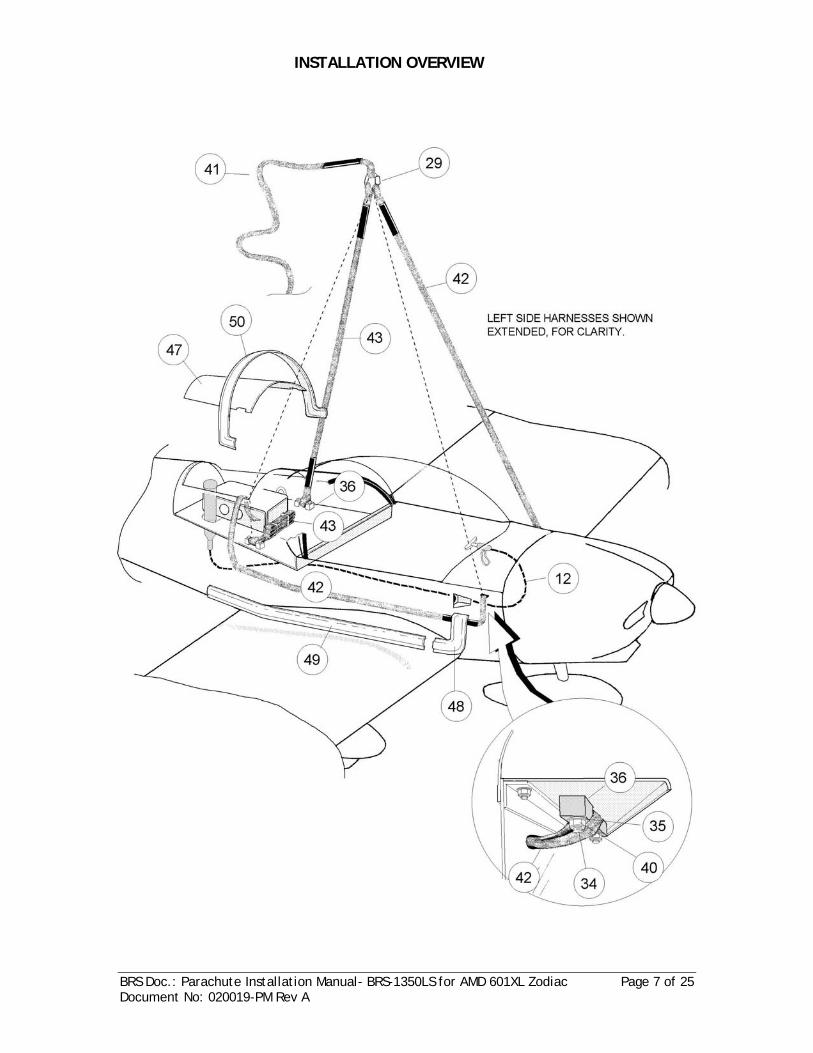
BRS Doc.: Parachute Installation Manual- BRS-1350LS for AMD 601XL Zodiac Page 7 of 25 Document No: 020019-PM Rev A
INSTALLATION OVERVIEW

BRS Doc.: Parachute Installation Manual- BRS-1350LS for AMD 601XL Zodiac Page 8 of 25 Document No: 020019-PM Rev A

BRS Doc.: Parachute Installation Manual- BRS-1350LS for AMD 601XL Zodiac Page 9 of 25 Document No: 020019-PM Rev A
ITEM QTY. PART NO. DESCRIPTION
1 1 008411-01 IGNITER / TUBE ASSEMBLY
2 3 005033-01 PLUG, CAP, SMALL
3 1 004035-01 SCREW, 10-24 X 5/8
4 1 004055-01 WASHER, EXT. TOOTH, #10 S.S.
5 1 005040-01 PLUG, CAP, 1”
6 1 004081-01 SCREW, NYLON 8-32 X ½”
7 1 002151-01 CASE, MOTOR, T2-400
8 2 002569-01 O-RING, SPACERS
9 1 008450-01 CARTRIDGE, T2-400
10 1 002550-01 * BULKHEAD, FORWARD
11 1 003216-01 CAP, ROCKET
12 1 008040-18 108” ACTIVATION ASSEMBLY
13 1 008062-01 HANDLE MOUNT, FLAT
14 4 004200-01 WASHER, .281 X .063 (FENDER)
15 1 005062-01 LINK, QUICK 1/8” S.S.
16 1 001644-01 INCREMENTAL BRIDLE, BRS 460
17 1 005037-01 PIN, CURVED, RELEASE
18 1 001015-01 PARACHUTE ASSEMBLY, 1350 LSA
19 1 001347-01 SLEEVE, DEPLOYMENT 8.5 X 250”
20 1 001344-01 BAG, SOFTPACK 15X10X6”
21 1 006243-01 LABEL, NAMEPLATE, BRS 1350 LSA
22 1 003068-01 TRAY, SOFTPACK 15X10.5”
23 8 004042-01 SCREW, ¼-20 X ¾”
24 20 004010-01 WASHER, FLAT ¼”
25 8 004001-01 NUT,NYLOCK ¼”
26 A/R 004000-01 CABLE TIE, 10 ¾”
27 4 004025-01 CABLE TIE, PLASTIC 4”
28 2 005063-01 LINK, STAND-OFF
29 2 005061-01 LINK, QUICK, ½” S.S.
30 2 004041-01 SCREW, ¼-20 X 5/8”
31 1 003201-01 PEDESTAL, ROCKET
32 4 004058-01 SCREW, SET ¼-20 X ¼”
PARTS LIST – 601XL Zodiac, BRS 1350 LSA

BRS Doc.: Parachute Installation Manual- BRS-1350LS for AMD 601XL Zodiac Page 10 of 25 Document No: 020019-PM Rev A
33 1 003227 ROCKET EXTENSION
34 8 AMD SUPPLIED PART BOLT, AN5-12A
35 16 004133 WASHER, 5/16
36 4 003205 CLAMP, BRIDLE
37 8 AMD SUPPLIED PART AN525 10R7
38 8 004148 NUT, 10-32 LOCKING
39 8 004166 WASHER, #10
40 8 004134 NUT, 5/16-24
41 1 007195-07 60” KEVLAR, MAIN BRIDLE C82/60C
42 2 007895-19 132” KEVLAR, FRONT HARNESSES C160/132C12
43 2 007195-19 132” KEVLAR, REAR HARNESSES, C154/132C
44 1 006230-01 LABEL “STAY CLEAR,DANGER”
45 2 006231-01 LABEL “BALLISTIC WARNING”
46 2 006206-11 LABEL, BRS 6 LOGO
47 1 005008 EGRESS PANEL (Plastic, Thermal Molder)
48 2 P/N 6N30-2 FRONT STRAP COVERS, RIGHT / LEFT
49 2 P/N 6N31-3 STRAP SIDE COVERS
50 1 P/N 6N30-1 REAR STRAP COVER
Following items must be installed in aircraft prior to parachute system installation!
51 1 ea. 6N31-1 REAR ATTACH ANGLE, UPPER LEFT / RIGHT
52 2 6N31-2 REAR ATTACH ANGLE, LOWER
53 1 6B6-4R FRONT ATTACH GUSSET, RIGHT
54 1 6B6-4L FRONT ATTACH GUSSET , LEFT
55 2 AMD SUPPLIED PART BOLT, AN3-4A
56 2 AMD SUPPLIED PART WASHER 3/16”
57 2 AMD SUPPLIED PART NUT, NYLOCK AN3
58 1 AMD SUPPLIED PART ¾” X ¾” X .093” ALUM. ANGLE EXTRUSION
59 3 AMD SUPPLIED PART ¾” X ¾” X .025 ALUM. ANGLE EXTRUSION
60 A/R AMD SUPPLIED PART 1/8” ALUM. BLIND (POP) RIVETS
Forward Bulkheads (item 10) may come in one of two different types, as shown. Items in Red depict non-BRS supplied parts.

BRS Doc.: Parachute Installation Manual- BRS-1350LS for AMD 601XL Zodiac Page 11 of 25 Document No: 020019-PM Rev A
1.1 Mark out top of turtle-deck for cutting
out of egress hole. Lay pattern out so hole will be parallel with longitudinal axis of airplane. Centerline of hole should be on centerline of airplane. Mark hole 14.5” x 19” (approx). Allow at least ½” lip to allow for riveting cover in place.
1.2 File and sand perimeter of hole to ensure
no sharp edges or burrs.
1.3 Remove Parachute from Tray (item 22).
Place Tray in baggage area and align with egress hole. Rocket should have at least 1” clearance from the right and rear edges of egress hole. Cut hole for rocket to penetrate floor of baggage area.
1.4 Secure 1350 Tray to baggage floor with
Screws ¼-20x3/4” (item 23), Nut Nylock ¼” (item 25) Washer ¼” (item 24) and Washer .281 (item 14). Use larger Fender Washer on bottom.
1. PARACHUTE ASSEMBLY INSTALLATION

BRS Doc.: Parachute Installation Manual- BRS-1350LS for AMD 601XL Zodiac Page 12 of 25 Document No: 020019-PM Rev A
1.5 Install Parachute back into Tray, with
the closing flap towards rear of aircraft. Secure Parachute to Tray by passing Velcro attaching tabs through associated slots in Tray. Pull up on tabs as much as possible and secure Velcro.
1.6 Re-attach Parachute Riser (webbing
loop) to Link (item 29). Do not close gate at this time.

BRS Doc.: Parachute Installation Manual- BRS-1350LS for AMD 601XL Zodiac Page 13 of 25 Document No: 020019-PM Rev A
2.1 Cut an access hole for each Kevlar Front
Harness to enter the fuselage on both sides, aft of the firewall. Hole Dimension: 1.25 x .50” Oval. Hole should be centered to line up with Bridle Clamp (item 36) holes on corner gusset, and positioned just under upper longeron. Note: File and sand edges to remove all burrs.
2.2 Install Front Harnesses by routing the long loop end through pre-cut hole, and attaching to Bridle Clamp (item 36) using hardware as shown in inset on page 7.
2.3 Approximately 6” below hole, turn
Harness over on itself in order to make the 90 deg. turn. Hold in position with tape until ready to cover. Use Front Strap Cover (item 48) for correct positioning.
2.4 Use Rear Strap Cover (item 50) to
determine proper final positioning of Kevlar Harness as it runs parallel with fuselage. Tape Harness in place. Note: Harnesses may be held in place with double-sided carpet tape, if necessary.
2. HARNESS ASSEMBLY INSTALLATION

BRS Doc.: Parachute Installation Manual- BRS-1350LS for AMD 601XL Zodiac Page 14 of 25 Document No: 020019-PM Rev A
2.5 Route Front Kevlar Harnesses into Egress
hole, and tape in place. Make notches in supplied ABS plastic sheet for Front Harnesses. Position Egress Panel over hole with an even overlap and drill holes for 1/8” blind rivets. 40-60 mm pitch around circumference. Temporarily, secure Egress Panel over hole with Cleco fasteners, and from the inside, mark a line around the Panel at the edge of the aircraft skin.
2.6 Position .025 Alum Angles (item 59) with the vertical flange oriented towards the Egress Panel (item 47), as shown in inset. Match drill holes for riveting. File edges to remove all burrs. Aluminum Angle is installed to give support to edge of hole and to protect parachute from getting caught on rivet heads.
2.7 View shows aluminum forward hole edge stiffener angle installed. (Aluminum angle side stiffeners not yet installed) Vertical flange of forward stiffener is “fluted” to allow for curvature of turtle-deck.
2.8
Remove the Egress Panel. Using an “Exacto” knife, score the Panel over the line previously marked. You want about half material thickness worth of blade penetration. Install Egress Panel. Seal around edges with appropriate sealant or paint-able silicone.

BRS Doc.: Parachute Installation Manual- BRS-1350LS for AMD 601XL Zodiac Page 15 of 25 Document No: 020019-PM Rev A
2.9 Attach 132” Rear Harnesses (item 43) to
pre-installed rear attach hard-points using the Bridle Clamps (item36). Secure each Bridle Clamp with hardware specified on page 6.
2.10 If not already done so, replace 4 of the
rivets securing the skin to the longeron with 4: AN525-10R7 (item 37) plus nuts and washers, as depicted. Do this on both sides of aircraft.
2.11 View showing installed AN 525-10R7 on
right side of aircraft.
Install Harness Covers using 1/8” dia. aluminum blind rivets with a 150mm to 250mm pitch. Use silicone or otherwise appropriate sealant around perimeter of Covers to prevent moisture contamination. Do not apply sealant to bottom edge of Side Strap Covers. This will allow trapped moisture to escape.

BRS Doc.: Parachute Installation Manual- BRS-1350LS for AMD 601XL Zodiac Page 16 of 25 Document No: 020019-PM Rev A
3.1 Attach one end of 60” Main Bridle (item
41) to the ½” Link (item 29) near the Softpack opening. Apply blue Loc-tite and close gate.
3.2 Insert a 10” Cable-tie into each bag strap
retaining slot as shown. These will be used to hold extra Link in place.
3.3 Connect “free end” of 60” Kevlar Bridle
(item 41) to Link and connect to Tray with Cable-ties installed previously. Use Cable-tie to secure Bridle to Tray below Link, as shown.
3.4 S-fold excess Kevlar Bridle along side of
Tray, secure with 10” Cable-ties.
3. HARNESS CONNECTION AND STOWAGE

BRS Doc.: Parachute Installation Manual- BRS-1350LS for AMD 601XL Zodiac Page 17 of 25 Document No: 020019-PM Rev A
3.5 Connect free ends of both Front and
Rear Kevlar Harnesses to extra ½” Link on end of Tray. Apply Loc-tite 242 (blue)…
3.6 …and close gate on Link. Do Not over-
tighten.
3.7 S-fold excess Harness sections and
secure with 10” Cable-ties, as shown.

BRS Doc.: Parachute Installation Manual- BRS-1350LS for AMD 601XL Zodiac Page 18 of 25 Document No: 020019-PM Rev A
4.1 Install Activation Handle underneath instrument panel, on the left side of the center console. This places it in pilots control, but reachable by passenger.
4.2 Install Activation Assembly support angle
between lower instrument panel flange and bottom firewall channel. Drill 17/64” hole through center console support angle for Handle installation. Note: Ensure that face of Handle extends at least 1.5” from instrument panel. Note use of large Nylon washer to extend Handle Assembly below support angle.
4.3 From Handle, route Activation Housing towards firewall in wide radius. Use 10” Cable-ties to secure Housing away from rudder pedals. Activation Housing should route through center console and between seats. Note: Ensure Housing is well secured with plastic Cable-ties and will not be subject to chafing on moving parts.
4.4 Where Activation Housing must route through bulkheads, make 7/8” hole for Cone Adapter to pass. Hole should utilize a grommet to reduce chance of chafing on Housing.
4. ACTIVATION HANDLE INSTALLATION
GROMMET

BRS Doc.: Parachute Installation Manual- BRS-1350LS for AMD 601XL Zodiac Page 19 of 25 Document No: 020019-PM Rev A
4.5 Route Activation Housing through center
console. Secure it so that it’s clear of elevator tube, rudder cables and any other moveable item. Use plenty of Cable-ties to ensure the Housing stays where installed.
4.6 Housing routing along floor, aft of seats.
4.7 Activation Housing routing aft from center panel, aft of seats. Notice rubber grommet installed.
4.8 Activation Housing secured with 10”
Cable-ties in multiple places to restrict movement during normal operations.

BRS Doc.: Parachute Installation Manual- BRS-1350LS for AMD 601XL Zodiac Page 20 of 25 Document No: 020019-PM Rev A
5.1 Assemble Rocket in accordance with BRS
Instruction Manual 6539, which is taped to the top of the small box the fuel is contained in.
5.2 Check to ensure you have the proper
parts and tools for installing the Activation Assembly (item 12). -Loc-tite 242 (blue) - 2: Cap Plug, small (item 2) - Hex wrench, 1/8” - Screw 10-24x5/8” (item 3) - Washer External Tooth (item 4)
5.3 Before beginning installation, ensure
Safety Pin and Flag is installed into the Handle Holder, as shown.
5.4 A safety wire is installed through the
Launch Tube into the Igniter Assembly for shipping purposes. Cut this wire…
5. ACTIVATION ASSEMBLY CONNECTION TO ROCKET

BRS Doc.: Parachute Installation Manual- BRS-1350LS for AMD 601XL Zodiac Page 21 of 25 Document No: 020019-PM Rev A
5.5 …and remove carefully. Discard Safety
Wire, it is no longer needed.
5.6 Apply a drop of Loc-tite 242 onto
threads of Screw (item 3).
5.7 Grasping cable with thumb and
forefinger, insert Activation Cable Loop into end of Launch Cone. Note: Bottom portion of Launch Tube is cut-away for clarity.
5.8 The “Actuator” on the bottom end of the Rocket Igniter Assembly has a slot in the end. The Loop on the end of the Activation Assembly must fit into this slot.

BRS Doc.: Parachute Installation Manual- BRS-1350LS for AMD 601XL Zodiac Page 22 of 25 Document No: 020019-PM Rev A
5.9 Once the Loop is definitely in the slot,
secure it with the 10-24 Screw and Lock Washer.
5.10 Run the Screw in until it’s snugged up
against the Actuator. Caution: When tightening the Screw, make sure that you remain “square” to it. Pushing too hard towards aft end of Launch Tube could cause ignition.
5.11 Properly installed Cable with seated
Screw and Lock Washer.
5.12 Before connecting Cone Adapter, tug on
Cable lightly towards rear with thumb and forefinger to ensure cable is actually captured by Screw. Note: It’s advisable to use a small flashlight and look in the end or sides to determine if Cable is properly inserted into slot, before closing everything up. DO NOT PROCEED UNTIL THIS IS VERIFIED!

BRS Doc.: Parachute Installation Manual- BRS-1350LS for AMD 601XL Zodiac Page 23 of 25 Document No: 020019-PM Rev A
5.13 Apply Loc-tite 242 to threads on end of
Launch Tube, and screw on Cone Adapter. (Black cylindrical part on end of Activation Assy.) Screw on by hand. May be snugged up with wrench, but do not over-tighten!
5.14 Install small Plastic Cap Plug (item 2)
into ½” access hole.

BRS Doc.: Parachute Installation Manual- BRS-1350LS for AMD 601XL Zodiac Page 24 of 25 Document No: 020019-PM Rev A
6.1 Pull open front flap of Softpack, and
expose Release Pin and small 1/8” Link (item 16). Open gate on Link. Note: Ensure Incremental Bridle (yellow strap assembly) is attached to Link.
6.2 Coil the Rocket Lanyards (cables) in a
manner which would not allow them to become a “knot” on deployment, and connect them to the Link (item 16).
6.3 Apply a drop of Loc-tite 242 (blue) or
equivalent, to threads on Link. Close gate, but do not over-tighten.
6.4 Place 2-3 small plastic Cable-ties (item
27) around Rocket Lanyards so they remain stowed. Close flap on Softpack.
6. ROCKET CONNECTION TO PARACHUTE

BRS Doc.: Parachute Installation Manual- BRS-1350LS for AMD 601XL Zodiac Page 25 of 25 Document No: 020019-PM Rev A
7. PLACARD PLACEMENT
7.1 Install “Ballistic Warning” label (item 45) aft of canopy on each side of airplane. Note: Labels have very aggressive adhesive – you will only get one attempt at placement before they’re on for good!
7.2 Install “Stay Clear, Danger” label (item 44) on parachute egress cover, in
position shown.