BALL SCREW JACK WITH TRAVELLING NUT MA BS Mod.B SJ BS … · Lift the screw jack from the holes on...
27
Servomech S.p.A. 01.05.27.BS-ModB.E - Rev. 00 DD (M/Y) 05/19 1 BALL SCREW JACK WITH TRAVELLING NUT MA BS Mod.B – SJ BS Mod.B – HS Installation, operation and maintenance manual Publication: 01.05.27.BS-ModB.E - Rev. 00 Date (M/Y) 05/19 Servomech S.p.A. Via M. Calari, 1 - 40011 Anzola dell’Emilia (BO) - ITALY Ph: + 39 051 6501711 Fax: + 39 051 734574 www.servomech.com [email protected]
Transcript of BALL SCREW JACK WITH TRAVELLING NUT MA BS Mod.B SJ BS … · Lift the screw jack from the holes on...

Servomech S.p.A. 01.05.27.BS-ModB.E - Rev. 00 DD (M/Y) 05/19 1
BALL SCREW JACK WITH TRAVELLING NUT
MA BS Mod.B – SJ BS Mod.B – HS
Installation, operation and maintenance manual
Publication: 01.05.27.BS-ModB.E - Rev. 00 Date (M/Y) 05/19
Servomech S.p.A. Via M. Calari, 1 - 40011 Anzola dell’Emilia (BO) - ITALY
Ph: + 39 051 6501711 Fax: + 39 051 734574 www.servomech.com [email protected]

Servomech S.p.A. 01.05.27.BS-ModB.E - Rev. 00 DD (M/Y) 05/19 2
WARNING
Read this manual before installing, operating or maintaining this screw jack. Failure
to follow safety precautions and instructions could cause screw jack failure and result
in serious injury, death or property damage.
This manual provides important information on how to work with the screw jack
safely and efficiently. The manual is part of the device, must always be kept in the
device’s direct proximity and should be available for personnel to read at any time.
Failure to comply with the installation, use and maintenance instructions indicated in
this manual will result in immediate termination of the warranty conditions of the
screw jack and completely relieve Servomech S.p.A. from any liability for damage
caused to persons and / or property.
Servomech S.p.A. it does not assume direct or indirect responsibility for an improper
use of the screw jack, not respecting the performances of the screw jack declared in
the catalogs.
The manufacturer will not be liable for damage to the screw jack or the equipment
into which the screw jack has been installed resulting from:
• disregarding this manual
• unintended use
• employment of untrained personnel
• unauthorized conversions
• technical modifications
• manipulation or removal of the screws on the device
• use of unapproved spare parts
The aforementioned conditions are therefore not contemplated and entail the
immediate termination of the guarantee and the immediate decay of any
responsibility on the part of Servomech S.p.A.
Servomech S.p.A. reserves the right to make changes to the screw jack and this
manual without giving any notice.

Servomech S.p.A. 01.05.27.BS-ModB.E - Rev. 00 DD (M/Y) 05/19 3
BALL SCREW JACK WITH TRAVELLING NUT
MA BS Mod.B – SJ BS Mod.B – HS
Installation, operation and maintenance manual
Contents 1 MODELS COVERED BY THIS DOCUMENT .................................................................................................... 5
2 IDENTIFICATION OF THE MANUFACTURER AND THE PRODUCT ................................................................ 5
2.1 Identification of the manufacturer ..................................................................................................... 5
2.2 Description of the product ................................................................................................................. 5
2.2.1 MA BS Mod.B Series ................................................................................................................... 5
2.2.2 SJ BS Mod.B Series ...................................................................................................................... 6
2.2.3 Serie HS ....................................................................................................................................... 6
2.3 Identification of the product .............................................................................................................. 7
3 TRASPORT AND HANDLING ........................................................................................................................ 8
4 USE RESTRICTION .....................................................................................................................................10
4.1 Intended use .....................................................................................................................................10
4.1.1 Use restrictions .........................................................................................................................10
4.1.2 Standard operating conditions .................................................................................................11
4.2 Personnel requirements / Qualifications .........................................................................................11
5 STORAGE ...................................................................................................................................................11
6 INSTALLATION ..........................................................................................................................................12
6.1 Safety warnings ................................................................................................................................12
6.2 Rotary encoder ENC.4 ......................................................................................................................13
6.3 Rotary encoder EH53 ........................................................................................................................13
6.4 Electric motor wiring ........................................................................................................................14
6.4.1 AC 3-phase asynchronous motor .............................................................................................14
6.4.2 AC 1-phase asynchronous motor with balanced winding ........................................................16
6.4.3 DC motor ..................................................................................................................................17
6.5 Screw jack installation ......................................................................................................................19
7 COMMISSIONING AND USE ......................................................................................................................21
8 LUBRICATION ............................................................................................................................................22
9 MAINTENANCE .........................................................................................................................................23
9.1 Maintenance of MA BS Mod.B screw jacks ......................................................................................23
9.1.1 Lubrication of the ball screw ....................................................................................................23
9.1.2 Lubrication of the gearbox .......................................................................................................23

Servomech S.p.A. 01.05.27.BS-ModB.E - Rev. 00 DD (M/Y) 05/19 4
9.2 Maintenance of SJ BS Mod.B screw jacks .........................................................................................24
9.2.1 Lubrication of the ball screw ....................................................................................................24
9.2.2 Lubrication of the gearbox .......................................................................................................24
9.3 Maintenance of HS screw jacks ........................................................................................................25
Servomech S.p.A. 01.05.27.BS-ModB.E - Rev. 00 DD (M/Y) 05/19 5
1 MODELS COVERED BY THIS DOCUMENT The present manual is referred to following products:
Ball screw jack with travelling nut MA Series: MA 5 BS Mod.B – MA 10 BS Mod.B – MA 25 BS Mod.B – MA
50 BS Mod.B – MA 80 BS Mod.B – MA 150 BS Mod.B – MA 200 BS Mod.B – MA 350 BS Mod.B
Ball screw jack with travelling nut SJ Series: SJ 5 BS Mod.B – SJ 10 BS Mod.B – SJ 25 BS Mod.B –
SJ 50 BS Mod.B – SJ 100 BS Mod.B – SJ150 BS Mod.B – SJ 200 BS Mod.B – SJ 200 BS Mod.B – SJ 250 BS Mod.B
– SJ 300 BS Mod.B – SJ 600 BS Mod.B – SJ 800 BS Mod.B
Ball screw jack with travelling nut HS Series: HS 10 – HS 25 – HS 50 – HS 100 – HS 150 – HS 200
2 IDENTIFICATION OF THE MANUFACTURER AND THE PRODUCT
2.1 Identification of the manufacturer
SERVOMECH S.p.A. S.U.
Via Monaldo Calari, 1 40011 Anzola dell’Emilia (BO) ITALY Ph. +39 051 6501 711 Fax. +39 051 7345 74 Website: www.servomech.com e-mail: [email protected]
2.2 Description of the product
For all the technical characteristics of the product (performance, features, dimensions) refer to the
technical catalog.
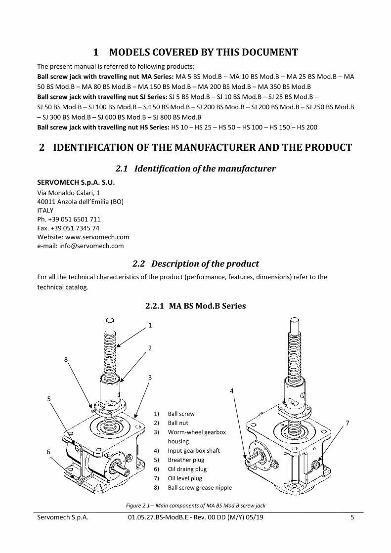
2.2.1 MA BS Mod.B Series
Figure 2.1 – Main components of MA BS Mod.B screw jack
1
1) Ball screw
2) Ball nut
3) Worm-wheel gearbox
housing
4) Input gearbox shaft
5) Breather plug
6) Oil draing plug
7) Oil level plug
8) Ball screw grease nipple
2
3
4 5
6
7
8

Servomech S.p.A. 01.05.27.BS-ModB.E - Rev. 00 DD (M/Y) 05/19 6
2.2.2 SJ BS Mod.B Series
Figure 2.2 – Main components of SJ BS Mod.B screw jack
2.2.3 Serie HS
Figure 2.3 – Main components of HS screw jack
SJ 5 ÷ SJ 300 BS Mod.B SJ 600 - SJ 800 BS Mod.B
1) Ball screw
2) Ball nut
3) Worm-wheel gearbox housing
4) Input gearbox shaft
5) Ball screw grease nipple
6) Gearbox grease nipple
1
2
3 4
5
6
1) Ball screw
2) Ball nut
3) Bevel gearbox housing
4) Input gearbox shaft
5) Ball screw grease nipple
1
2
3
4
5
6
1
2
3 4
5
Servomech S.p.A. 01.05.27.BS-ModB.E - Rev. 00 DD (M/Y) 05/19 7
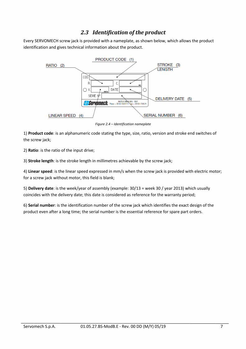
2.3 Identification of the product
Every SERVOMECH screw jack is provided with a nameplate, as shown below, which allows the product
identification and gives technical information about the product.
Figure 2.4 – Identification nameplate
1) Product code: is an alphanumeric code stating the type, size, ratio, version and stroke end switches of
the screw jack;
2) Ratio: is the ratio of the input drive;
3) Stroke length: is the stroke length in millimetres achievable by the screw jack;
4) Linear speed: is the linear speed expressed in mm/s when the screw jack is provided with electric motor;
for a screw jack without motor, this field is blank;
5) Delivery date: is the week/year of assembly (example: 30/13 = week 30 / year 2013) which usually
coincides with the delivery date; this date is considered as reference for the warranty period;
6) Serial number: is the identification number of the screw jack which identifies the exact design of the
product even after a long time; the serial number is the essential reference for spare part orders.

Servomech S.p.A. 01.05.27.BS-ModB.E - Rev. 00 DD (M/Y) 05/19 8
3 TRASPORT AND HANDLING Screw jacks with mounted ball screw and all accessories can be often difficult to handle because of
their overall dimensions. Therefore, it is recommended to pay attention and care during the handling
and transport of screw jack not to damage mechanical parts and / or accessories and to prevent risks
for the personnel in charge of this activity.
The packaging must be lifted and moved with care and in a safe way.
Use only safety-inspected and suitable load hoisting equipment.
When transporting the product with attached motor, always provide support for the motor, or
remove the motor before transporting the product.
Lift the screw jack from the holes on the housing, using slings or eyebolts.
If necessary, provide support for the screw jack from ball screw.
During lifting operation make sure that the weight of the screw jack is well balanced.
DO NOT lift the screw jack from the ball screw end or the ball nut.
DO NOT lift the screw jack from the motor.
Prevent the screw jack from swinging during lifting operations.
Ball screw jack are NOT self-locking. Never lift the screw jack from the ball nut as the screw jack could
be back driven by its own weight.
During transport make sure the ball nut does not go out from the screw. If this happens, please
contact SERVOMECH.
Figure 3.1 – Transport and handling

Servomech S.p.A. 01.05.27.BS-ModB.E - Rev. 00 DD (M/Y) 05/19 9
Before hoisting the screw jack, check the weight on the following table:
MA 5 BS MA 10 BS MA 25 BS MA 50 BS MA 80 BS MA 150 BS MA 200 BS MA 350 BS
Mass of the screw
jack w/o ball screw
[kg] 2.2 4.3 13 26 26 48 75 145
SJ 5 BS SJ 10 BS SJ 25 BS SJ 50 BS SJ 100 BS SJ 150 BS SJ 200 BS SJ 250 BS SJ 300 BS SJ 600 BS SJ 800 BS
Mass of the screw
jack w/o ball screw
[kg] 1.5 2.3 10.4 25 35 55 75 75 120 260 800
HS 10 HS 25 HS 50 HS 100 HS 150 HS 200
Mass of the screw
jack w/o ball screw
[kg] 5.9 11.3 20 38 67 120
In case of doubt, consult SERVOMECH S.p.A. to get the appropriate information and prevent any kind of
damage!

Servomech S.p.A. 01.05.27.BS-ModB.E - Rev. 00 DD (M/Y) 05/19 10
4 USE RESTRICTION The information contained in this chapter provides important prescriptions for operating safely during all
phases of the product's life.
Not knowing or not complying with these provisions can generate dangerous situations that could cause
damage to equipment and risks for the safety of persons.
4.1 Intended use
Screw jacks are used to perform very different functions within machines. It is the responsibility of the
machine builder to design the application in compliance with the laws in force in the specific sector and in
the field of safety, in compliance with the requirements provided in the product catalog and in this manual.
SCREW JACKS ARE ELECTRIC AXIS, WHATEVER DRIVER OR CONTROL WILL BE USED: THE SELECTION
OF THE PRODUCT AS STROKE, SPEED, TYPE OF LIMIT SWITCHES, MOTOR AND BRAKE, MUST BE DONE
ACCORDING TO THE BEHAVIOR EXPECTED, IN FUNCTION OF THE TYPE OF CONTROL CHOOSEN AND
THE STATIC AND DYNAMIC BEHAVIOR OF THE SYSTEM IN WHICH THE SCREW JACK IS PLACED!
The screw jacks have been designed and built to operate mobile parts of various types, shapes and construction, in the ways and within the limits set out in the descriptions and tables of the technical data in the catalog and in this user manual. The screw jacks are designed to work with a purely axial applied load. They must be subjected to the loading and speed conditions specified in the catalog. Modification of parts of the screw jack or replacement of components with different and non-original parts is not permitted. The replacement of components with original spare parts is carried out only by Servomech S.p.A. Any different use is to be considered improper and therefore potentially dangerous for the safety of the operators, as well as such as to void the contractual guarantee. In the event of particular processing requirements, we recommend consulting our sales department. Every modification must be authorized by Servomech S.p.A. with written documents.
ANY OTHER USE OUTSIDE THAT THAT JUST DESCRIBED IS NOT PERMITTED BY SERVOMECH S.p.A.
4.1.1 Use restrictions
Screw jacks can not be used for unforeseen applications.
Any utilization of this device beyond its intended purpose may lead to potentially hazardous situations.
Therefore:
Strictly adhere to all safety precautions and instructions in this operating manual.
Do not allow this device to be subjected to weather conditions, strong UV rays, corrosive or explosive air media as well as other aggressive media (*).
Do not modify, retool or change the structural design or individual components of the screw jack.
Never use the device outside of the technical application and operational limits.
THE USE OF THE SCREW JACK IN DIFFERENT CONDITIONS THAN JUST DESCRIBED MUST BE
PREVIOUSLY DECLARED AND AGREED WITH SERVOMECH, SINCE A SPECIAL EQUIPMENT OF THE
PRODUCT MUST BE PROVIDED.

Servomech S.p.A. 01.05.27.BS-ModB.E - Rev. 00 DD (M/Y) 05/19 11
4.1.2 Standard operating conditions
The screw jacks must be used in an environment whose conditions comply with the provisions of Servomech S.p.A. The works necessary for obtaining and maintaining that conditions are in charge of the owner and, where applicable, are in charge of the end user.
The screw jack must be installed and used indoor only, in dry area with environmental conditions as specified below:
Temperature range +0°C ÷ +40°C
Relative atmospheric humidity 5% ÷ 85%
No build up of condensation
THE USE OF THE SCREW JACK IN DIFFERENT CONDITIONS THAN JUST DESCRIBED MUST BE PREVIOUSLY DECLARED AND AGREED WITH SERVOMECH, SINCE A SPECIAL EQUIPMENT OF THE PRODUCT MUST BE PROVIDED.
4.2 Personnel requirements / Qualifications
This manual must be made available to the personnel in charge of installation, start up and use of the screw
jack. It is the responsibility of the machine builder:
use personnel with the necessary qualifications for the installation and commissioning of the screw jack;
periodically check the qualification of the assigned personnel;
check that the personnel in charge are aware of the contents of this manual.
5 STORAGE Do not store outside.
Storage should be dry and dust-free.
Keep away from any aggressive media.
Protect from UV radiation.
Avoid mechanical vibrations.
Storage temperature: 0 to +50 °C.
Relative atmospheric humidity: max. 95% (no build up of condensation).
To store longer than 6 months, take care of moving the input shafts to prevent damages to sealings.
Also check that all unpainted parts are adequately protected (oiled and /or greased) to prevent oxidation.
Servomech S.p.A. 01.05.27.BS-ModB.E - Rev. 00 DD (M/Y) 05/19 12
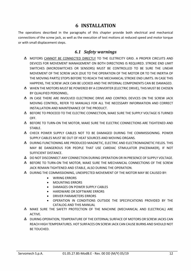
6 INSTALLATION The operations described in the paragraphs of this chapter provide both electrical and mechanical
connections of the screw jack, as well as the execution of test motions at reduced speed and motor torque
or with small displacement steps.
6.1 Safety warnings
MOTORS CANNOT BE CONNECTED DIRECTLY TO THE ELETRICITY GRID. A PROPER CIRCUITS AND
DEVICES FOR MOVEMENT MANAGEMENT ON BOTH DIRECTIONS IS REQUIRED. STROKE END LIMIT
SWITCHES (MICROSWITCHES OR SENSORS) MUST BE CONTROLLED TO BE SURE THE LINEAR
MOVEMENT OF THE SCREW JACK (DUE TO THE OPERATION OF THE MOTOR OR TO THE INERTIA OF
THE MOVING PARTS) STOPS BEFORE TO REACH THE MECHANICAL STROKE END LIMITS. IN CASE THIS
HAPPENS, THE SCREW JACK CAN BE LOCKED AND THE INTERNAL COMPONENTS CAN BE DAMAGED.
WHEN THE MOTORS MUST BE POWERED BY A CONVERTER (ELECTRIC DRIVE), THIS MUST BE CHOSEN
BY QUALIFIED PERSONNEL.
IN CASE THERE ARE INVOLVED ELECTRONIC DRIVE AND CONTROL DEVICES ON THE SCREW JACK
MOVING CONTROL, REFER TO MANUALS FOR ALL THE NECESSARY INFORMATION AND CORRECT
INSTALLATION AND MAINTENANCE OF THE PRODUCT.
BEFORE TO PROCEED TO THE ELECTRIC CONNECTION, MAKE SURE THE SUPPLY VOLTAGE IS TURNED
OFF.
BEFORE TO TURN-ON THE MOTOR, MAKE SURE THE ELECTRIC CONNECTIONS ARE TIGHTENED AND
STABLE.
CHECK POWER SUPPLY CABLES NOT TO BE DAMAGED DURING THE COMMISSIONING. POWER
SUPPLY CABLES MUST BE OUT OF HEAT SOURCES AND MOVING ORGANS.
DURING FUNCTIONING ARE PRODUCED MAGNETIC, ELECTRIC AND ELECTROMAGNETIC FIELDS. THIS
MAY BE DANGEROUS FOR PEOPLE THAT USE CARDIAC STIMULATOR (PACEMAKER), IF NOT
SUFFICIENT DISTANCE.
DO NOT DISCONNECT ANY CONNECTION DURING OPERATION OR IN PRESENCE OF SUPPLY VOLTAGE.
BEFORE TO TURN-ON THE MOTOR, MAKE SURE THE MECHANICAL CONNECTIONS OF THE SCREW
JACK REMAIN TIGHTENED AND STABLE, ALSO DURING THE OPERATION.
DURING THE COMMISSIONING, UNEXPECTED MOVEMENT OF THE MOTOR MAY BE CAUSED BY:
WIRING ERRORS
MOUNTING ERRORS
DAMAGES ON POWER SUPPLY CABLES
HARDWARE OR SOFTWARE ERRORS
DRIVER PARAMETERS ERRORS
OPERATION IN CONDITIONS OUTSIDE THE SPECIFICATIONS PROVIDED BY THE CATALOG AND THIS MANUAL
MAKE SURE THE SAFETY PROTECTION OF THE MACHINE (MECHANICAL AND ELECTRICAL) ARE
ACTIVE.
DURING OPERATION, TEMPERATURE OF THE EXTERNAL SURFACE OF MOTORS OR SCREW JACKS CAN
REACH HIGH TEMPERATURES. HOT SURFACES ON SCREW JACK CAN CAUSE BURNS AND SHOULD NOT
BE TOUCHED.
Servomech S.p.A. 01.05.27.BS-ModB.E - Rev. 00 DD (M/Y) 05/19 13
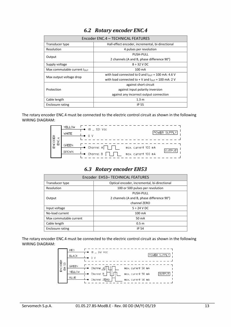
6.2 Rotary encoder ENC.4
Encoder ENC.4 – TECHNICAL FEATURES
Transducer type Hall-effect encoder, incremental, bi-directional
Resolution 4 pulses per revolution
Output PUSH-PULL
2 channels (A and B, phase difference 90°)
Supply voltage 8 ÷ 32 V DC
Max commutable current IOUT 100 mA
Max output voltage drop with load connected to 0 and IOUT = 100 mA: 4.6 V
with load connected to + V and IOUT = 100 mA: 2 V
Protection
against short circuit
against input polarity inversion
against any incorrect output connection
Cable length 1.3 m
Enclosure rating IP 55
The rotary encoder ENC.4 must be connected to the electric control circuit as shown in the following WIRING DIAGRAM:
6.3 Rotary encoder EH53
Encoder EH53– TECHNICAL FEATURES
Transducer type Optical encoder, incremental, bi-directional
Resolution 100 or 500 pulses per revolution
Output
PUSH-PULL
2 channels (A and B, phase difference 90°)
channel ZERO
Input voltage 5 ÷ 24 V DC
No-load current 100 mA
Max commutable current 50 mA
Cable length 0.5 m
Enclosure rating IP 54
The rotary encoder ENC.4 must be connected to the electric control circuit as shown in the following WIRING DIAGRAM:

Servomech S.p.A. 01.05.27.BS-ModB.E - Rev. 00 DD (M/Y) 05/19 14
6.4 Electric motor wiring
6.4.1 AC 3-phase asynchronous motor
Connect the motor to the power unit of the plant or to the driver according to the following wiring diagrams,
related to the motor type:
(a) AC 3-phase motor without brake
(b) AC 3-phase motor with DC brake directly powered with rectifier
(c) AC 3-phase motor with 3-phase brake directly powered
(d) AC 3-phase motor with DC brake separately powered AC 1-phase with rectifier
(e) AC 3-phase motor with AC 3-phase brake separately powered
(f) AC 3-phase motor with DC brake separately powered AC 2-phase with rectifier
(g) AC 3-phase motor with DC brake separately powered
In case of brake motor:
the brake is NORMALLY CLOSED (NEGATIVE action). When the power supply is switched off, the brake is engaged. The brake opens only when power is supplied;
if the brake is wired directly to the connecting pins of the terminal box, it does not require any power supply;
if the brake is wired separately, make sure that the correct voltage is used;
if the brake is equipped with hand release device, make sure that the brake is engaged before starting the linear actuator.
Figure 6.1 – Electric wiring diagrams to power supply of AC 3-ph motor
K1, K2, K3 = contactor
M = motor
Br = brake

Servomech S.p.A. 01.05.27.BS-ModB.E - Rev. 00 DD (M/Y) 05/19 15
Figure 6.1 – Electric wiring diagrams to power supply of AC 3-ph motor
Figure 6.2 – Electric wiring diagrams to motor terminal board of AC 3-ph motor
IN CASE OF ELECTRIC MOTOR DIFFERENT FROM THE ABOVE MENTIONED, PLEASE REFER TO INSTALLATION INSTRUCTIONS SUPPLIED BY THE MANUFACTURER.
K1, K2, K3 = contactor
M = motor
Br = brake

Servomech S.p.A. 01.05.27.BS-ModB.E - Rev. 00 DD (M/Y) 05/19 16
6.4.2 AC 1-phase asynchronous motor with balanced winding
Connect the motor to the power unit of the plant or to the driver according to the following wiring diagrams,
related to the motor type:
(a) AC 1-phase motor without brake
(b) AC 1-phase motor with DC brake separately powered AC 1-phase with rectifier
In case of brake motor:
the brake is NORMALLY CLOSED (NEGATIVE action). When the power supply is switched off, the brake
is engaged. The brake opens only when power is supplied;
the brake is wired separately, make sure that the correct voltage is used;
if the brake is equipped with hand release device, make sure that the brake is engaged before starting
the linear actuator.
Figure 6.3 – Electric wiring diagrams to power supply of AC 1-ph motor
Figure 6.4 – Electric wiring diagrams to motor terminal board of AC 1-ph motor
IN CASE OF ELECTRIC MOTOR DIFFERENT FROM THE ABOVE MENTIONED, PLEASE REFER TO
INSTALLATION INSTRUCTIONS SUPPLIED BY THE MANUFACTURER.
K1, K2, K3 = contactor
M = motor
Br = brake
Servomech S.p.A. 01.05.27.BS-ModB.E - Rev. 00 DD (M/Y) 05/19 17
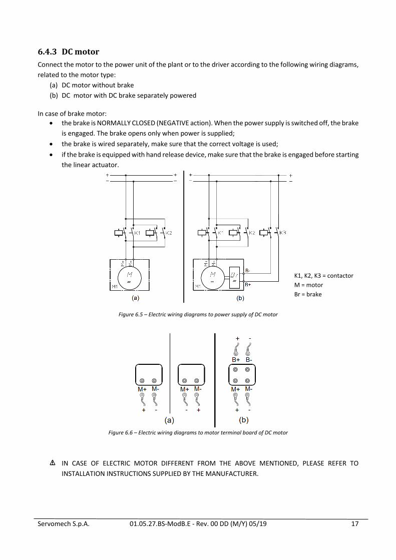
6.4.3 DC motor
Connect the motor to the power unit of the plant or to the driver according to the following wiring diagrams,
related to the motor type:
(a) DC motor without brake
(b) DC motor with DC brake separately powered
In case of brake motor:
the brake is NORMALLY CLOSED (NEGATIVE action). When the power supply is switched off, the brake
is engaged. The brake opens only when power is supplied;
the brake is wired separately, make sure that the correct voltage is used;
if the brake is equipped with hand release device, make sure that the brake is engaged before starting
the linear actuator.
Figure 6.5 – Electric wiring diagrams to power supply of DC motor
Figure 6.6 – Electric wiring diagrams to motor terminal board of DC motor
IN CASE OF ELECTRIC MOTOR DIFFERENT FROM THE ABOVE MENTIONED, PLEASE REFER TO
INSTALLATION INSTRUCTIONS SUPPLIED BY THE MANUFACTURER.
K1, K2, K3 = contactor
M = motor
Br = brake

Servomech S.p.A. 01.05.27.BS-ModB.E - Rev. 00 DD (M/Y) 05/19 18
After electric motor installation, check if the screw jack shifting direction is compatible to the indications on the control unit, by powering the electric motor on VERY BRIEFLY.
Figure 6.7 – MA BS Mod.B and SJ BS Mod.B screw jack shifting directions
Figure 6.8 – HS screw jack shifting directions
If the screw jack shifting directions are not compatible:
A) THREE-PHASE MOTOR: invert any wire pair (U1 V1, or U1 W1, or V1 W1) into the terminal board;
B) SINGLE-PHASE MOTOR: change the contact (V1 W1);
C) DIRECT CURRENT MOTOR: invert contacts of the two motor supply cables.

Servomech S.p.A. 01.05.27.BS-ModB.E - Rev. 00 DD (M/Y) 05/19 19
6.5 Screw jack installation
BALL SCREW JACK ARE NOT SELF-LOCKING. BEFORE TO APPLY ANY AXIAL LOAD ON THE BALL SCREW,
LOCK THE INPUT SHAFT OR USE THE MOTOR BRAKE.
ALL MECHANICAL AND ELECTRICAL PROTECTION MUST BE INSTALLED AND ACTIVATED TO PREVENT
DAMAGE TO PERSONS OR PROPERTY.
Check that all plant fixing elements are well machined and cleaned, and that they fit the dimensions
of the screw jack fixing elements they have to be fixed to.
If the position of the ball nut have to be changed during installation, screw/unscrew the nut on the
ball screw shaft.
To change the position of the ball nut without rotating it, rotate the input shaft of the screw jack in
proper direction (see Fig. 6.7 - 6.8).
For screw jacks with electric motor: power the motor with limited speed and torque values, in order
to avoid possible damages in case of a mechanical stop is reached.
In case of screw jack with bellow protection (B): DO NOT TWIST THE BELLOW
ONLY FOR MA BS Mod.B SCREW JACKS: the gearbox is oil lubricated; to avoid leakage during
transport, the BREATHER of the housing is replaced by a plug. The breather is supplied unmounted,
with the screw jack. AFTER INSTALLATION, PLEASE MOUNT THE BREATHER IN THE PROPER HOLE
POSITION, AS SHOWN IN FIG 2.1.
THE BREATHER HOLE POSITION IS INDICATED BY A MARKER.
THE BREATHER MUST ALWAYS BE IN UPPER POSITION.
The installation of many screw jacks for SYNCHRONIZED lifting movement requires particular attention on
two different factors:
alignment of load support points on travelling ball nuts;
use of connecting shafts and couplings with high torsional stiffness, to assure a perfect synchronism
of all lifting points.
DO NOT SET THE LENGTH OF THE SCREW JACK OVER ITS EXTREME VALUES:
o “Lc” = retracted screw jack length
o “La” = extended screw jack length
Figure 6.9 – “Lc” and “La” dimensions
Dimensions “Lc” and “La” are indicated on the check sheet supplied with the screw jack.

Servomech S.p.A. 01.05.27.BS-ModB.E - Rev. 00 DD (M/Y) 05/19 20
Fit the screw jack to the plant in order to have ONLY AXIAL LOAD applied to the ball screw.
Provide RADIAL support to the CYLINDRICAL ROTATING END (N) of the ball screw with a bearing.
The cylindrical end (N) must be free to move in axial direction: DO NOT FIX IT.
Check the axis of the ball screw and the screw jack fixing surface are perpendicular.
Check the supporting surfaces of the screw jack and the load are parallel.
In case of screw jack with TRUNNION MOUNT (SC): the pins on the housing and the pins on the acme
nut must be PARALLEL.
Figure 6.10 – Installation of the screw jack
RIGHT WORKING OF THE SCREW JACK AND PLANT CANNOT BE GUARANTED IF SIDE OR NOT AXIAL
LOAD ARE APPLIED TO THE BALL SCREW.

Servomech S.p.A. 01.05.27.BS-ModB.E - Rev. 00 DD (M/Y) 05/19 21
7 COMMISSIONING AND USE
SERVOMECH ball screw jacks are supplied lubricated and ready to be used.
Before to start commissioning and activation, the following checks must be carried out:
Shifting direction check
Check if the screw jack shifting direction is compatible to the indications on the control unit, by
powering the electric motor on VERY BRIEFLY. If not, see Section 6.4.
TO ALLOW THE TRANSLATION OF THE BALL NUT, THE NUT ROTATION MUST BE REACTED BY USING
EXTERNAL GUIDES.
Check of extreme working positions
Check if the extreme dimensions of the screw jack “Lc” and “La” (see Fig. 6.9) are compatible with
extreme positions of the plant component that has to be moved.
Check the stroke limit switches on the plant (if present) are working properly.
Measure the initial length of the screw jack, then run the screw jack GRADUALLY from the control
unit, in order to reach the plant to its more distant extreme position.
Check continuously the current screw jack length during the motion.
Repeat the same procedure for the other extreme position.
TO AVOID DAMAGES, DO NOT TRAVEL OVER THE EXTREME STROKE VALUES Lc and La! The Lc and La
dimensions are indicated on the check sheet supplied with the product.
DO NOT REACH STROKE END MECHANICAL STOP.
Commissioning
At this stage it is possible to start commissioning:
Carry out one complete working cycle, without load.
Carry out some complete working cycles, increasing gradually the load, until full load is reached.
Servomech S.p.A. 01.05.27.BS-ModB.E - Rev. 00 DD (M/Y) 05/19 22
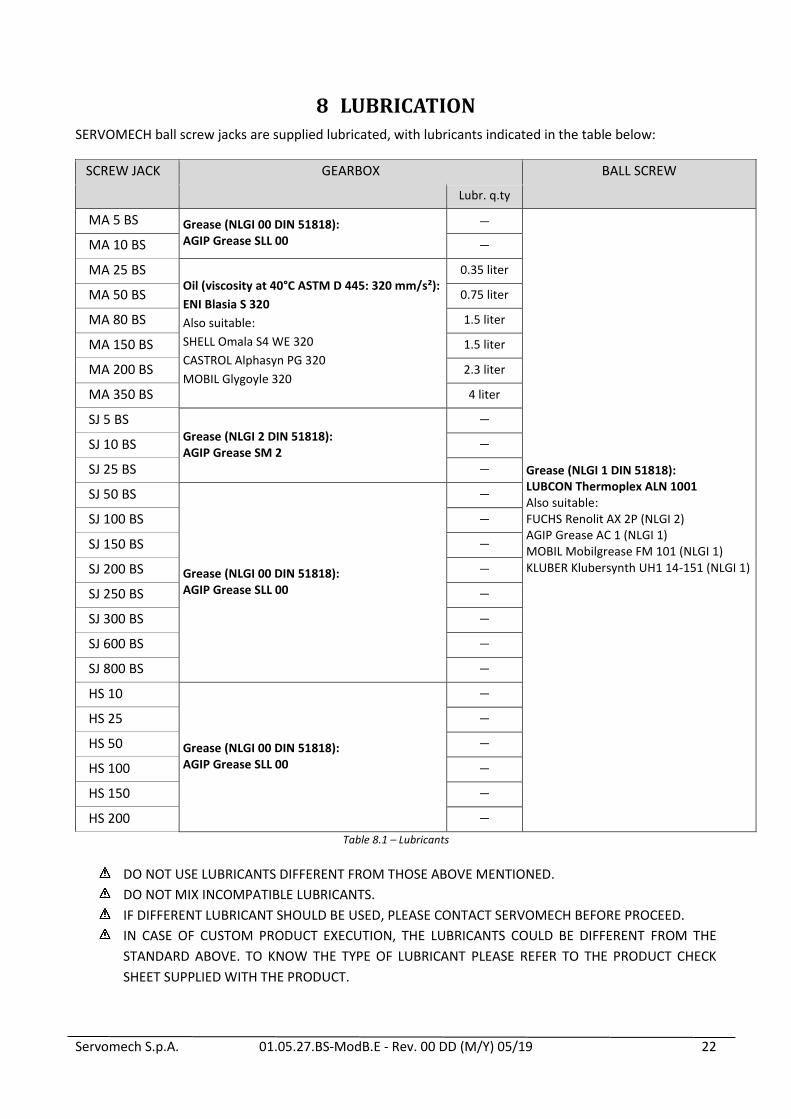
8 LUBRICATION SERVOMECH ball screw jacks are supplied lubricated, with lubricants indicated in the table below:
SCREW JACK GEARBOX BALL SCREW
Lubr. q.ty
MA 5 BS Grease (NLGI 00 DIN 51818): AGIP Grease SLL 00
—
Grease (NLGI 1 DIN 51818): LUBCON Thermoplex ALN 1001 Also suitable: FUCHS Renolit AX 2P (NLGI 2) AGIP Grease AC 1 (NLGI 1) MOBIL Mobilgrease FM 101 (NLGI 1) KLUBER Klubersynth UH1 14-151 (NLGI 1)
MA 10 BS —
MA 25 BS Oil (viscosity at 40°C ASTM D 445: 320 mm/s²):
ENI Blasia S 320
Also suitable:
SHELL Omala S4 WE 320
CASTROL Alphasyn PG 320
MOBIL Glygoyle 320
0.35 liter
MA 50 BS 0.75 liter
MA 80 BS 1.5 liter
MA 150 BS 1.5 liter
MA 200 BS 2.3 liter
MA 350 BS 4 liter
SJ 5 BS Grease (NLGI 2 DIN 51818): AGIP Grease SM 2
—
SJ 10 BS —
SJ 25 BS —
SJ 50 BS
Grease (NLGI 00 DIN 51818): AGIP Grease SLL 00
—
SJ 100 BS —
SJ 150 BS —
SJ 200 BS —
SJ 250 BS —
SJ 300 BS —
SJ 600 BS —
SJ 800 BS —
HS 10
Grease (NLGI 00 DIN 51818): AGIP Grease SLL 00
—
HS 25 —
HS 50 —
HS 100 —
HS 150 —
HS 200 —
Table 8.1 – Lubricants
DO NOT USE LUBRICANTS DIFFERENT FROM THOSE ABOVE MENTIONED.
DO NOT MIX INCOMPATIBLE LUBRICANTS.
IF DIFFERENT LUBRICANT SHOULD BE USED, PLEASE CONTACT SERVOMECH BEFORE PROCEED.
IN CASE OF CUSTOM PRODUCT EXECUTION, THE LUBRICANTS COULD BE DIFFERENT FROM THE
STANDARD ABOVE. TO KNOW THE TYPE OF LUBRICANT PLEASE REFER TO THE PRODUCT CHECK
SHEET SUPPLIED WITH THE PRODUCT.
Servomech S.p.A. 01.05.27.BS-ModB.E - Rev. 00 DD (M/Y) 05/19 23
9 MAINTENANCE
9.1 Maintenance of MA BS Mod.B screw jacks
The GEARBOX is long-life lubricated and will not require any further relubrication. Additional
lubrication can be done only in case of verified lubricant leakage from the gearbox. In such a case,
use the lubricant type indicated in Tab. 8.1 or an equivalent one. The quantity of lubricant to be
added depends on the leaked volume.
The BALL SCREW requires periodic relubrication. The lubrication interval is the linear stroke indicated
in Table 9.1, or at the latest after 1 year of time. Please use lubricant indicated in Table 8.1 or
equivalent.
Every 2 months time interval: visual inspections of screw jack conditions, cleaning of dirty parts of
the screw jack.
In case of lubricant leakage, contact SERVOMECH.
9.1.1 Lubrication of the ball screw
WARNING! THE PLANT MUST BE STOPPED BEFORE BEGINNING ANY MAINTENANCE OPERATION.
Relube the ball screw using proper grease nipple positioned on the ball nut (comp. n. 8, Fig. 2.1, page
4).
Apply the grease quantity indicated in Tab 9.1 with several partial quantities.
Travel over the entire stroke between one lubricating operation and the next.
At the end of lubricating procedure, extend and retract the screw jack over its entire stroke for 3 full
cycles.
If necessary, remove excess of lubricant from the ball screw.
9.1.2 Lubrication of the gearbox
WARNING! THE PLANT MUST BE STOPPED BEFORE BEGINNING ANY MAINTENANCE OPERATION.
THE REFILL OR REPLACEMENT OF GEARBOX LUBRICANT CAN NOT BE DONE ON MA 5 BS, MA 10 BS
SCREW JACKS, AS THEY ARE GREASE LUBRICATED.
The GEARBOX is long-life lubricated. Refill or replace of lubricant can be done only in case of verified
lubricant leakage from the gearbox.
Lubricant refill
Remove the breather plug (comp. n. 5, Fig. 2.1, page 4).
Add oil type indicated in Tab. 8.1 or equivalent, until the oil level is visible through the oil level plug
(comp. n. 7, Fig. 2.1, page 4). The oil level should be approximately in the middle of the inspection
plug.
Replace the sealing washer on the breather plug with a new one and fix it.
Lubricant replacement
Completely drain the oil inside the housing by removing the drain plug (comp. n. 6, Fig. 2.1, page 4).
Replace the sealing washer on the drain plug with a new one and fix it on the proper hole.
Remove the breather plug (comp. n. 5, Fig. 2.1, page 4) and add oil until the oil level is visible
through the oil level plug (comp. n. 7, Fig. 2.1, page 4). The oil quantity to be added is roughly the
quantity indicated in Tab. 8.1. The oil level should be approximately in the middle of the inspection
plug.
Then replace the sealing washer on the breather plug with a new one and fix it on the proper hole.

Servomech S.p.A. 01.05.27.BS-ModB.E - Rev. 00 DD (M/Y) 05/19 24
9.2 Maintenance of SJ BS Mod.B screw jacks
The GEARBOX is long-life lubricated and will not require any further relubrication. Additional
lubrication can be done only in case of verified lubricant leakage from the gearbox. In such a case,
use the lubricant type indicated in Tab. 8.1 or an equivalent one. The quantity of lubricant to be
added depends on the leaked volume.
The BALL SCREW requires periodic relubrication. The lubrication interval is the linear stroke indicated
in Table 9.1, or at the latest after 1 year of time. Please use lubricant indicated in Table 8.1 or
equivalent.
Every 2 months time interval: visual inspections of screw jack conditions, cleaning of dirty parts of
the screw jack.
In case of lubricant leakage, contact SERVOMECH.
9.2.1 Lubrication of the ball screw
WARNING! THE PLANT MUST BE STOPPED BEFORE BEGINNING ANY MAINTENANCE OPERATION.
Relube the ball screw using proper grease nipple positioned on the ball nut (comp. n. 5, Fig. 2.2, page
5).
Apply the grease quantity indicated in Tab 9.1 with several partial quantities.
Travel over the entire stroke between one lubricating operation and the next.
At the end of lubricating procedure, extend and retract the screw jack over its entire stroke for 3 full
cycles.
If necessary, remove excess of lubricant from the ball screw.
9.2.2 Lubrication of the gearbox
WARNING! THE PLANT MUST BE STOPPED BEFORE BEGINNING ANY MAINTENANCE OPERATION.
The GEARBOX is long-life lubricated. Refill of lubricant can be done only in case of verified lubricant
leakage from the gearbox.
Lubricant refill
Add grease type indicated in Tab. 8.1 or equivalent, using proper grease nipple positioned on the
housing (comp. n. 6, Fig. 2.2, page 5).
The quantity of lubricant to be added depends on the leaked volume.

Servomech S.p.A. 01.05.27.BS-ModB.E - Rev. 00 DD (M/Y) 05/19 25
9.3 Maintenance of HS screw jacks
The GEARBOX is long-life lubricated and will not require any further relubrication.
The BALL SCREW requires periodic relubrication. The lubrication interval is the linear stroke indicated
in Table 9.1, or at the latest after 1 year of time. Please use lubricant indicated in Table 8.1 or
equivalent.
Every 2 months time interval: visual inspections of screw jack conditions, cleaning of dirty parts of
the screw jack.
In case of lubricant leakage, contact SERVOMECH.
Ball screw lubrication
WARNING! THE PLANT MUST BE STOPPED BEFORE BEGINNING ANY MAINTENANCE OPERATION.
Relube the ball screw using proper grease nipple positioned on the ball nut (comp. n. 5, Fig. 2.3, page
5).
Apply the grease quantity indicated in Tab. 9.1 with several partial quantities.
Travel over the entire stroke between one lubricating operation and the next.
At the end of lubricating procedure, extend and retract the screw jack over its entire stroke for 3 full
cycles.
If necessary, remove excess of lubricant from the ball screw.

Servomech S.p.A. 01.05.27.BS-ModB.E - Rev. 00 DD (M/Y) 05/19 26
Ball screw
diameter × lead
Balls
Dw [mm]
n° starts
Np
n° circuits
i
Ball nut code Lubrication interval
[km of stroke]
Grease q.ty
[cm³]
Ø 16 × 5 3.175 1 3 SFN-_.16.05.3R 50 1.5
Ø 16 × 5 3.175 1 6 SFN-_.16.05.6R 50 2
Ø 16 × 10 3.175 1 3 SFN-_.16.10.3R 100 1.5
Ø 16 × 16 3.175 2 2 SFN-_.16.16.2R-2 160 1
Ø 20 × 5
3.175 1 3 SFN-_.20.05.3R 50 2
3.175 1 5 SFN-_.20.05.5R 50 2
3.175 1 8 SFN-_.20.05.8R 50 3
Ø 20 × 10 3.175 1 3 SFN-_.20.10.3R 100 2
Ø 20 × 20
3.175 1 2 SFN-_.20.20.2R 200 2
3.175 2 2 SFN-_.20.20.2R-2 200 1.5
3.175 1 2F SFN-_.20.20.2R-F 200 1.5
Ø 25 × 5 3.175 1 3 SFN-_.25.05.3R 50 2
5 SFN-_.25.05.5R 50 2.5
Ø 25 × 6 3.969 1 5 SFN-_.25.06.5R 60 3.5
Ø 25 × 10 3.969 1 3 SFN-_.25.10.3R 100 3
Ø 25 × 25 3.175 2 2 SFN-_.25.25.2R-2 250 1.5
Ø 32 × 5 3.175 1 4 SFN-_.32.05.4R 50 3
Ø 32 × 10
6.350 1 3 SFN-_.32.10.3R 100 8.0
6.350 1 4 SFN-_.32.10.4R 100 9
6.350 1 5 SFN-_.32.10.5R 100 10
Ø 32 × 20 6.350 1 3 SFN-_.32.20.3R 200 9
3F SFN-_.32.20.3R-F 200 6
Ø 32 × 32 6.350 1 2 SFN-_.32.32.2R 320 6
2 2 SFN-_.32.32.2R-2 320 4
Ø 40 × 10 6.350 1 5 SFN-_.40.10.5R 100 13
Ø 40 × 20 6.350 1 3 SFN-_.40.20.3R 200 12
3F SFN-_.40.20.3R-F 200 9
Ø 40 × 40 6.350 1 2 SFN-_.40.40.2R 400 9
2 2 SFN-_.40.40.2R-2 400 7
Table 9.1 – Maintenance of the ball screw

Servomech S.p.A. 01.05.27.BS-ModB.E - Rev. 00 DD (M/Y) 05/19 27
Ball screw
diameter × lead
Balls
Dw [mm]
n° starts
Np
n° circuits
i
Ball nut code Lubrication interval
[km of stroke]
Grease q.ty
[cm³]
Ø 50 × 5 3.175 1 5 SFN-_.50.05.5R 50 23
Ø 50 × 10 7.144 1 5 SFN-_.50.10.5R 100 19
6 SFN-_.50.10.6R 100 21
Ø 50 × 20 7.144 1 4 SFN-_.50.20.4R 200 21
Ø 50 × 40 7.144 1 2 SFN-_.50.40.2R 400 13
Ø 63 × 10 7.144 1 5 SFN-_.63.10.5R 100 26
Ø 63 × 20 9.525 1 4 SFN-_.63.20.4R 200 45
Ø 63 × 40 9.525 1 3 SFN-_.63.40.3R 400 35
Ø 80 × 10 7.144 1 6 SFN-_.80.10.6R 100 36
Ø 80 × 16 9.525 1 5 SFN-_.80.16.5R 160 61
Ø 80 × 20
12.700 1 4 SFN-_.80.20.4R 200 87
9.525 1 5 SFN-_.80.20.5R 200 42
12.700 1 6 SFN-_.80.20.6R 200 89
Ø 80 × 40 12.700 1 2 SFN-_.80.40.2R 400 48
Ø 100 × 16 9.525 1 5 SFN-_.100.16.5R 160 84
Ø 100 × 20 12.7 1 5 SFN-_.100.20.5R 200 129
Ø 120 × 20 15.875 1 7 SFN-_.120.20.7R 200 277
Ø 120 × 32 25.400 1 6 SFN-_.120.32.6R 320 498
Ø 140 × 32 25.400 1 7 SFN-_.140.32.7R 320 622
Tabella 9.1 – Maintenance of the ball screw