Ball-Float Traps UNA PN 1 – PN 1 0 - Gazza Anselmo · UNA 14h, 14v Flanged EN PN 25 150 150 160...
5
Pressure/Temperature Ratings and Designs **) Type PN ∆PMX [bar] Werkstoffe Druck-/Temperaturgrenzen EN ASTM 1 ) PMA / TMA PMA / TMA UNA 14 25 13 EN-JS 1049 – 25 bar / 20 °C 15 bar / 350 °C UNA 23 16 13 EN-JL 1040 A126 Cl. B 16 bar / 120 °C 9.6 bar / 300 °C UNA 16 40 22 1.0460; 1.0619 A105; A216 WCB 40 bar / 20 °C 23.1 bar / 400 °C UNA 25 40 32 EN-JS 1049 – 32 bar / 250 °C 25 bar / 350 °C UNA 26 40 32 1.0460; 1.0619 A105; A216 WCB 32 bar / 250 °C 3 ) 21 bar / 400 °C UNA 27 h 63 45 1.5419 A217 WC1 56 bar / 250 °C 40.6 bar / 450 °C UNA 38 100 80 1.5415 4 ) A182-F1 100 bar / 150 °C 44 bar / 500 °C UNA 39 160 140 1.7335 A182 F12 160 bar / 300 °C 35 bar / 550 °C UNA-Special Typ 62 16 16 EN-JL 1040 A126 Cl. B 16 bar / 120 °C 9.6 bar / 300 °C UNA-Special 25 22 1.0619 A216 WCB 22.6 bar / 120 °C 14.4 bar / 400 °C UNA 25 22 1.0619 A216 WCB 22.6 bar / 120 °C 14.4 bar / 400 °C UNA-Special 63 45 1.5419 A217 WC1 56 bar / 250 °C 40.6 bar / 450 °C UNA 16 A 40 22 1.4404 2 ) 1.4308 2 ) A182 F 316L 2 ) A351 CF8 2 ) 40 bar / –196 °C / 20 °C 25.8 bar / 300 °C UNA 26 h 40 32 1.4408 A351 CF8 M 40 bar / 20 °C 25.8 bar / 300 °C 1 ) ASTM nearest equivalent grade is stated for guidance only. Physical and chemical properties comply with EN grade. 2 ) Body/cover material 3 ) UNA 26 DN 40, DN 50: 26 bar/250 °C 4 ) Body 1.5415, cover 1.7357 ** ) For more information see data sheet. h: for horizontal lines Ball-Float Traps UNA PN 1 – PN 10 Features of the UNA series • Unaffected by back pressure and condensate temperature • No loss of live steam due to continuous water seal at the seat • No banking-up of condensate even with extreme load and pressure fluctuations • Particularly well suited for heat exchangers controlled from the steam side • Unaffected by dirt • Automatic thermostatic air-venting (Duplex design) • Ideal for discharging cold condensates, distil- lates and condensates derived from chemical products (Simplex design) • Repairable in-line • Thanks to the rolling ball valve only reduced operating forces and small control units are required (compact, lightweight design for large flowrates) • Internals made from corrosion-resistant stainless steels UNA 23/25/26 h DN 15 – 50 UNA 23/25/26 v DN 40, 50 with MAX regulator Application Condensate discharge without banking-up, even at varying operating conditions and back pressure. Automatic air-venting (Duplex design). Also for the discharge of cold condensates and distillates, and for draining gas and compressed air systems (Simplex design). L UNA 27 h DN 25 – 50 L2 UNA 39 DN 15, 25, 50 L1 STAINLESS STEEL UNA 14/16 v DN 15 – 25 L STAINLESS STEEL
Transcript of Ball-Float Traps UNA PN 1 – PN 1 0 - Gazza Anselmo · UNA 14h, 14v Flanged EN PN 25 150 150 160...

Pressure/Temperature Ratings and Designs **)
Type PN ∆PMX[bar]
Werkstoffe Druck-/Temperaturgrenzen
EN ASTM 1) PMA / TMA PMA / TMA
UNA 14 25 13 EN-JS 1049 – 25 bar / 20 °C 15 bar / 350 °C
UNA 23 16 13 EN-JL 1040 A126 Cl. B 16 bar / 120 °C 9.6 bar / 300 °C
UNA 16 40 221.0460;1.0619
A105; A216 WCB
40 bar / 20 °C 23.1 bar / 400 °C
UNA 25 40 32 EN-JS 1049 – 32 bar / 250 °C 25 bar / 350 °C
UNA 26 40 321.0460;1.0619
A105;A216 WCB
32 bar / 250 °C3) 21 bar / 400 °C
UNA 27 h 63 45 1.5419 A217 WC1 56 bar / 250 °C 40.6 bar / 450 °C
UNA 38 100 80 1.54154) A182-F1 100 bar / 150 °C 44 bar / 500 °C
UNA 39 160 140 1.7335 A182 F12 160 bar / 300 °C 35 bar / 550 °C
UNA-SpecialTyp 62
16 16 EN-JL 1040 A126 Cl. B 16 bar / 120 °C 9.6 bar / 300 °C
UNA-Special 25 22 1.0619 A216 WCB 22.6 bar / 120 °C 14.4 bar / 400 °C
UNA 25 22 1.0619 A216 WCB 22.6 bar / 120 °C 14.4 bar / 400 °C
UNA-Special 63 45 1.5419 A217 WC1 56 bar / 250 °C 40.6 bar / 450 °C
UNA 16 A 40 22
1.44042)1.4308 2)
A182 F 316L2)A351 CF8 2)
40 bar / –196 °C / 20 °C
25.8 bar / 300 °C
UNA 26 h 40 32 1.4408 A351 CF8 M 40 bar / 20 °C 25.8 bar / 300 °C
1) ASTM nearest equivalent grade is stated for guidance only. Physical and chemical properties comply with EN grade.2) Body/cover material 3) UNA 26 DN 40, DN 50: 26 bar/250 °C4) Body 1.5415, cover 1.7357
**) For more information see data sheet.h: for horizontal lines
Ball-Float Traps UNAPN 1� – PN 1�0
Features of the UNA series• Unaffected by back pressure and condensate
temperature
• No loss of live steam due to continuous water seal at the seat
• No banking-up of condensate even with extreme load and pressure fluctuations
• Particularly well suited for heat exchangers controlled from the steam side
• Unaffected by dirt
• Automatic thermostatic air-venting (Duplex design)
• Ideal for discharging cold condensates, distil-lates and condensates derived from chemical products (Simplex design)
• Repairable in-line
• Thanks to the rolling ball valve only reduced operating forces and small control units are required (compact, lightweight design for large flowrates)
• Internals made from corrosion-resistant stainless steels
UNA 23/25/26 hDN 15 – 50
UNA 23/25/26 vDN 40, 50 with MAX regulator
ApplicationCondensate discharge without banking-up, even at varying operating conditions and back pressure. Automatic air-venting (Duplex design). Also for the discharge of cold condensates and distillates, and for draining gas and compressed air systems (Simplex design).
L
UNA 27 hDN 25 – 50
L2
UNA 39DN 15, 25, 50
L1
STAiNLESS
STEEL
UNA 14/16 vDN 15 – 25
L
STAiNLESS
STEEL
A1
Ball-Float Traps UNAPN 1� – PN 1�0
L1
L2
L1
L2
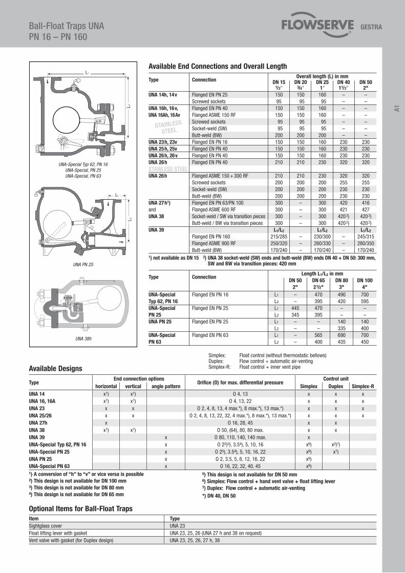
UNA-Special Typ 62, PN 16UNA-Special, PN 25UNA-Special, PN 63
UNA PN 25
Available End Connections and Overall Length
Optional items for Ball-Float Trapsitem TypeSightglass cover UNA 23Float lifting lever with gasket UNA 23, 25, 26 (UNA 27 h and 38 on request)Vent valve with gasket (for Duplex design) UNA 23, 25, 26, 27 h, 38
Simplex: Float control (without thermostatic bellows)Duplex: Flow control + automatic air-ventingSimplex-R: Float control + inner vent pipe
Type Connection Length L1/L2 in mm
DN 50 DN 65 DN 80 DN 100 2" 21/2" 3" 4"UNA-Special Flanged EN PN 16 L1 – 470 490 700Typ 62, PN 16 L2 – 395 420 595UNA-Special Flanged EN PN 25 L1 445 470 – –PN 25 L2 345 395 – –UNA PN 25 Flanged EN PN 25 L1 – – 140 140 L2 – – 335 400UNA-Special Flanged EN PN 63 L1 – 565 690 700PN 63 L2 – 400 435 450
Type Connection Overall length (L) in mm
DN 15 DN 20 DN 25 DN 40 DN 50 1/2" 3/4" 1" 11/2" 2"UNA 14h, 14v Flanged EN PN 25 150 150 160 – – Screwed sockets 95 95 95 – –UNA 16h, 16v, Flanged EN PN 40 150 150 160 – –UNA 16Ah, 16Av Flanged ASME 150 RF 150 150 160 – – Screwed sockets 95 95 95 – – Socket-weld (SW) 95 95 95 – – Butt-weld (BW) 200 200 200 – –UNA 23h, 23v Flanged EN PN 16 150 150 160 230 230UNA 25h, 25v Flanged EN PN 40 150 150 160 230 230UNA 26h, 26v Flanged EN PN 40 150 150 160 230 230UNA 26h Flanged EN PN 40 210 210 230 320 320STAiNLESS STEELUNA 26h Flanged ASME 150 + 300 RF 210 210 230 320 320 Screwed sockets 200 200 200 255 255 Socket-weld (SW) 200 200 200 230 230 Butt-weld (BW) 200 200 200 230 230UNA 27h1) Flanged EN PN 63/PN 100 300 – 300 420 416and Flanged ASME 600 RF 300 – 300 421 427UNA 38 Socket-weld / SW via transition pieces 300 – 300 4202) 4202) Butt-weld / BW via transition pieces 300 – 300 4202) 4202)UNA 39 L1/L2 L1/L2 L1/L2
Flanged EN PN 160 215/285 – 230/300 – 245/315 Flanged ASME 900 RF 250/320 – 260/330 – 280/350 Butt-weld (BW) 170/240 – 170/240 – 170/2401) not available as DN 15 2) UNA 38 socket-weld (SW) ends and butt-weld (BW) ends DN 40 + DN 50: 300 mm, SW and BW via transition pieces: 420 mm
STAiNLESS
STEEL
UNA 38h
Available Designs
TypeEnd connection options
Orifice (O) for max. differential pressureControl unit
horizontal vertical angle pattern Simplex Duplex Simplex-RUNA 14 x1) x1) O 4, 13 x x xUNA 16, 16A x1) x1) O 4, 13, 22 x x xUNA 23 x x O 2, 4, 8, 13, 4 max.*), 8 max.*), 13 max.*) x x xUNA 25/26 x x O 2, 4, 8, 13, 22, 32, 4 max.*), 8 max.*), 13 max.*) x x xUNA 27h x O 16, 28, 45 x xUNA 38 x1) x1) O 50, (64), 80, 80 max. x xUNA 39 x O 80, 110, 140, 140 max. xUNA-Special Typ 62, PN 16 x O 22)3), 3.54), 5, 10, 16 x6) x2)7)UNA-Special PN 25 x O 25), 3.54), 5, 10, 16, 22 x6) x7)UNA PN 25 x O 2, 3.5, 5, 8, 12, 16, 22 x6)UNA-Special PN 63 x O 16, 22, 32, 40, 45 x6)1) A conversion of “h” to “v” or vice versa is possible 2) This design is not available for DN 100 mm 3) This design is not available for DN 80 mm 4) This design is not available for DN 65 mm
5) This design is not available for DN 50 mm 6) Simplex: Flow control + hand vent valve + float lifting lever 7) Duplex: Flow control + automatic air-venting*) DN 40, DN 50

UNA 27 h
Ball-Float Traps UNAPN 1� – PN 1�0
Capacity ChartsThe charts show the maximum hot condensate capacities for the range of float-controlled orifices (O) and sizes available.
UNA 14, UNA 16 UNA 23, UNA 25, UNA 26
, AO 22
UNA 38, AO 50, 64, 80
UNA 23, 25, 26 max.
UNA 38, AO 80 max

A1
Ball-Float Traps UNAPN 1� – PN ��
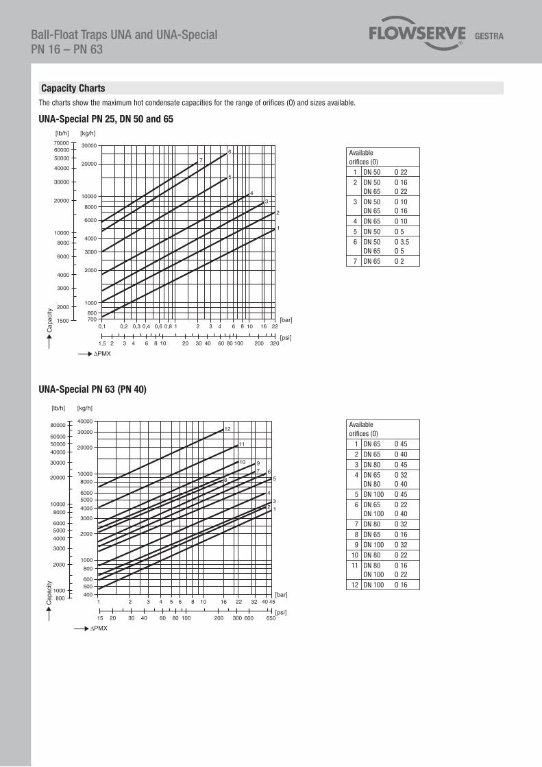
Capacity ChartsThe charts show the maximum hot condensate capacities for the range of orifices (O) and sizes available.
UNA PN 25, DN 80 and 100Available orifices (O)
1 DN 80 O 22 2 DN 80 O 16 DN 100 O 22 3 DN 80 O 12 4 DN 100 O 16 5 DN 80 O 8 DN 100 O 12 6 DN 80 O 5 DN 100 O 8 7 DN 80 O 3.5 8 DN 100 O 5 9 DN 80 O 2 DN 100 O 3.5 10 DN 100 O 2
Available orifices (O)
1 DN 65 O 16 2 DN 65 O 10 DN 80 O 16 3 DN 80 O 10 4 DN 100 O 16 5 DN 65 O 5 6 DN 80 O 5 7 DN 65 O 2 DN 80 O 3.5 DN 100 O 10 8 DN 100 O 5 9 DN 100 O 3.5 10 DN 100 O 2
UNA-Special Typ 62, PN 1610
UNA 39, DN 15, 25 and 50
Ball-Float Traps UNA and UNA-SpecialPN 1� – PN ��
UNA-Special PN 63 (PN 40)
Available orifices (O)
1 DN 65 O 45 2 DN 65 O 40 3 DN 80 O 45 4 DN 65 O 32 DN 80 O 40 5 DN 100 O 45 6 DN 65 O 22 DN 100 O 40 7 DN 80 O 32 8 DN 65 O 16 9 DN 100 O 32 10 DN 80 O 22 11 DN 80 O 16 DN 100 O 22 12 DN 100 O 16
UNA-Special PN 25, DN 50 and 65
Capacity ChartsThe charts show the maximum hot condensate capacities for the range of orifices (O) and sizes available.
Available orifices (O)
1 DN 50 O 22 2 DN 50 O 16 DN 65 O 22 3 DN 50 O 10 DN 65 O 16 4 DN 65 O 10 5 DN 50 O 5 6 DN 50 O 3.5 DN 65 O 5 7 DN 65 O 2