Ball and Beam1
6
control-systems-principles.co.uk. Ball and Beam 1: Basics BALL AND BEAM 1: Basics Peter Wellstead: control systems principles.co.uk ABSTRACT: This is one of a series of white papers on systems modelling, analysis and control, prepared by Control Systems Principles.co.uk to give insights into important principles and processes in control. In control systems there are a number of generic systems and methods which are encountered in all areas of industry and technology. These white papers aim to explain these important systems and methods in straightforward terms. The white papers describe what makes a particular type of system/method important, how it works and then demonstrates how to control it. The control demonstrations are performed using models of real systems that I designed, and which have been developed for manufacture by TQ Education and Training Ltd in their CE range of equipment. This white paper is about a very useful and influencial laboratory system for teaching control of unstable systems – the Ball and Beam System. 1. What is the Ball and Beam? The ball and beam system is one of the most enduringly popular and important laboratory models for teaching control systems engineering. The ball and beam system is widely used because it is very simple to understand as a system, and yet the control techniques that can be studied it cover many important classical and modern design methods. It has a very important property – it is open loop unstable. Ball Beam Angle Beam Angle Motor Amplifier Beam Ball Position Motor Figure 1. The Ball and Beam System. The system (shown in figure 1) is very simple – a steel ball rolling on the top of a long beam. The beam is mounted on the output shaft of an electric motor and so the beam can be tilted about its centre axis by applying an electrical control signal to the motor amplifer. The position of the ball on the beam can be measured using a special sensor. The control job is to automatically regulate the position of the ball on the beam by changing the angle of the beam. This is a difficult control task because the ball does not stay in one place on the beam but moves with an acceleration that is proportional to the tilt of the beam. In control techology the system is open loop unstable because the system output (the ball position) increases without limit for a fixed input (beam angle). Feedback control must be used to keep the ball in a desired position on the beam. 1
-
Upload
saeed-asiri -
Category
Documents
-
view
213 -
download
1
Transcript of Ball and Beam1

control-systems-principles.co.uk. Ball and Beam 1: Basics
BALL AND BEAM 1: Basics
Peter Wellstead: control systems principles.co.uk
ABSTRACT: This is one of a series of white papers on systems modelling, analysis and control, prepared by Control Systems Principles.co.uk to give insights into important principles and processes in control. In control systems there are a number of generic systems and methods which are encountered in all areas of industry and technology. These white papers aim to explain these important systems and methods in straightforward terms. The white papers describe what makes a particular type of system/method important, how it works and then demonstrates how to control it. The control demonstrations are performed using models of real systems that I designed, and which have been developed for manufacture by TQ Education and Training Ltd in their CE range of equipment. This white paper is about a very useful and influencial laboratory system for teaching control of unstable systems – the Ball and Beam System.
1. What is the Ball and Beam?
The ball and beam system is one of the most enduringly popular and important laboratory models for teaching control systems engineering. The ball and beam system is widely used because it is very simple to understand as a system, and yet the control techniques that can be studied it cover many important classical and modern design methods. It has a very important property – it is open loop unstable.
Ball
Beam Angle
Beam AngleMotor Amplifier
Beam
Ball Position
Motor
Figure 1. The Ball and Beam System.
The system (shown in figure 1) is very simple – a steel ball rolling on the top of a long beam. The beam is mounted on the output shaft of an electric motor and so the beam can be tilted about its centre axis by applying an electrical control signal to the motor amplifer. The position of the ball on the beam can be measured using a special sensor.
The control job is to automatically regulate the position of the ball on the beam by changing the angle of the beam. This is a difficult control task because the ball does not stay in one place on the beam but moves with an acceleration that is proportional to the tilt of the beam. In control techology the system is open loop unstable because the system output (the ball position) increases without limit for a fixed input (beam angle). Feedback control must be used to keep the ball in a desired position on the beam.
1
control-systems-principles.co.uk. Ball and Beam 1: Basics
2. What is the Relevance of the Ball and Beam System?
Most control problems that we meet in practical world are straightforward to control. For a fixed input signal the output stays more or less constant. An important set of systems however are, either by design or nature, unstable and feedback control is essential to make them operate safely. Many modern industrial processes and technological systems are intrinsically unstable could be used without stabilizing feedback control.
Important practical examples of unstable systems are:
1. In the chemical process industries - the control of exo-thermic chemical reactions. If a chemical reaction generates heat and yet the reaction gets faster as temperature increases, then control must be used to stabilise the temperature of the chemical reaction to avoid a ‘run-away’ reaction. Exothermic reactions are used to produce many everyday chemical products – without feedback control these products would not be available to us.
2. In power generation – the position control of the plasma in the Joint European Torus (JET). The object here is to control the vertical position of a plasma ring inside a hollow donut-shaped metal container. The control is by using magnetic fields applied through the donut and the plasma moves vertically in an unstable manner in response to the control fields. To understand the problem, imagine pressing a wet ball of soap in between the flat of your (slipperly) hands. As you increase the pressure on the soap so it will slip out faster when you alter the relative angles of your hands, (it’s the same problem trying to hold a hamster). My team studied this problem (the plasma – not the soap/hamster) and supplied some preliminary system modelling knowledge and control solutions for the JET project – the JET engineers did the rest.
3. In aerospace – the control of a rocket or aircraft during vertical take-off. The angle of thruster jets or diverters must be continually controlled to prevent the rocket tumbling or the aircraft tipping. Without feedback control to stabilise the movement, there would be no space rockets and the famous Hawker Harrier ‘jump-jet’ would have remained a dream on the desks of Sir Sydney Camm and his engineers at the Hawker Aircraft Company.
The control of unstable systems is critically important to many of the most difficult control problems and must be studied in the laboratory. The problem is that real unstable systems are usually dangerous and cannot be brought into the laboratory. The ball and beam system was developed to resolve this paradox. It is a simple, safe mechanism and yet it has the important dynamic features of an unstable system. I first saw a ball and beam system many years ago while on a visit to Sweden and was immediately impressed by the concept. I designed a version of it and this has evolved into the CE106 Ball and Beam System that I will describe later in this white paper.
3. The Ball and Beam System Model
The complete description of the dynamics of the ball rolling on the beam is quite complicated and for control system design a simplified derivation (as given here) is used to give a model that is good for controller design.
The force that accelerates the ball as it rolls on the beam comes from the component of gravity that acts parallel to the beam. The dotted line in Figure 2 shows this force to be θsinmg . The ball actually accelerates along the beam by rolling, but we can simplify the derivation by assuming that the ball is sliding without friction along the beam. Then, using the equation force = mass × acceleration, the simplified ball and beam model is:
xmmg &&=θsin
Where, m is the mass of the ball, g is the gravitational constant,θ is the beam angle and x is the position of the ball on the beam.
2

control-systems-principles.co.uk. Ball and Beam 1: Basics
Figure 2. Ball Dynamics
For small angles, θsin is approximately equal to θ so the model becomes:
θgx =&& (1)
This is the basic model of the ball and beam system. It shows that the ball acceleration is proportional to to gravity and the angle of tilt of the beam. The beam angle θ is proportional to the motor angle control voltage u and the ball position x is read from a position sensor y. Replacing θ by the control voltage u, ball position by the sensor output y and combining actuator and sensor constants with the gravity constant we get a single constant b. This represents the overall gain of the response from control voltage input to measured output acceleration:
buy =&& (2)
This simple model of the ball and beam is a good approximation to the true system dynamics, and is the one normally used in text books, tutorial papers and design studies for controller design. A complete dynamical model of the Ball and Beam System is given in my book ‘Introduction to Physical System Modelling’ and in the documentation for the CE106 Ball and Beam System. For controller design, equation 2 is usually sufficient.
Now let us look at the transfer function and state space version of the model. The transfer function for the ball and beam is obtained from equation 2 as:
)()( 2 susbsx = (3)
If we define the system states to be the ball position and the ball velocity , then the state space equation is:
1x 2x
[ ] ⎥⎦
⎤⎢⎣
⎡=
⎥⎦
⎤⎢⎣
⎡+⎥
⎦
⎤⎢⎣
⎡⎥⎦
⎤⎢⎣
⎡=⎥
⎦
⎤⎢⎣
⎡
2
1
2
1
2
1
01
00010
xx
y
ubx
xxx&
&
(4)
The linear models given above are the basis of the controller design for ball and beam systems. A real ball and beam however has additional dynamic components due to the motor, plus non-linear and noise components that influence its control behaviour. The main non-linearities are Coulomb friction in the moving parts and the dead zone and saturation in the motor input amplifier – these should be solved by a
3
control-systems-principles.co.uk. Ball and Beam 1: Basics
position control loop on the beam motor. The feedback will have a linearising effect and the feedback will reduce the impact of the motor dynamics on the overall model. Noise can be a bigger problem – the measurement of the ball position is difficult and all ball position sensing methods have sensor noise. The ball and beam model is a very simple one. We only require one parameter – the gain parameter b . This can be obtained by measuring the time taken for the ball to accelerate from one end of the beam to the other for a fixed angle of the beam. The laws of motion can then be used to integrate up equation (1) and calculate b. For the CE106 Ball and Beam System (see below) the approximate value of b is 0.8.
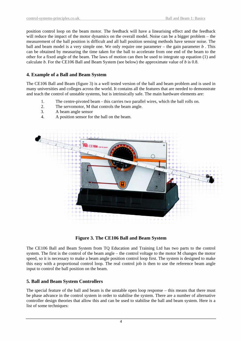
4. Example of a Ball and Beam System
The CE106 Ball and Beam (figure 3) is a well tested version of the ball and beam problem and is used in many universities and colleges across the world. It contains all the features that are needed to demonstrate and teach the control of unstable systems, but is intrinsically safe. The main hardware elements are:
1. The centre-pivoted beam - this carries two parallel wires, which the ball rolls on. 2. The servomotor, M that controls the beam angle. 3. A beam angle sensor 4. A position sensor for the ball on the beam.
Figure 3. The CE106 Ball and Beam System
The CE106 Ball and Beam System from TQ Education and Training Ltd has two parts to the control system. The first is the control of the beam angle – the control voltage to the motor M changes the motor speed, so it is necessary to make a beam angle position control loop first. The system is designed to make this easy with a proportional control loop. The real control job is then to use the reference beam angle input to control the ball position on the beam.
5. Ball and Beam System Controllers
The special feature of the ball and beam is the unstable open loop response – this means that there must be phase advance in the control system in order to stabilise the system. There are a number of alternative controller design theories that allow this and can be used to stabilise the ball and beam system. Here is a list of some techniques:
4

control-systems-principles.co.uk. Ball and Beam 1: Basics
1. Proportional plus derivative (PD) control 2. Phase Lead Compensation 3. State Observer with State Feedback Control 4. Linear Quadratic Regulator (LQR) 5. Linear Quadratic Gaussian (LQG) 6. Robust Control 7. Sliding Mode and Variable Structure Control 8. Fuzzy Control
Each of the above can be implemented as a continuous time method or a digital method based on Z transforms. All of these methods give an acceptable performance if designed with care by an expert. The ball position sensor noise is a special factor. The control system must have phase advance to stabilise the ball position, but phase advance can amplify noise at high frequencies, so a compromise is needed. The ball and beam system is a good example on which to investigate this kind of design/performance compromise. Variable structure control is impressive on the ball and beam because it is possible to ‘see’ the system output (the ball position) moving along the beam as if it were moving down a controller switching line. The list of controllers includes Elke’s pet hate – PD control – this is because derivative action is essential to stabilise the ball behaviour. The action of the derivative washout filter in this case is also essential in order to suppress problems with sensor noise, (see Elke’s white paper on Three Term Control). No integral action is needed as the system is a double integrator – Sorry Elke!
5. Example of a Ball and Beam Controller Design
Because it is open loop unstable, it necessary to have some kind of measurement of the ball velocity. The classical proportional plus derivative controller gets a velocity measure by differentiating the ball position. The classical phase lead compensator does something very similar. A better way of doing this is to use an observer based upon a model of the ball and beam to estimate the systems states, and use the state estimates (of ball position and velocity) in a state feedback controller. The state feedback will stabilise the ball position, and by choice of the observer dynamics it is possible to ‘trade off’ the sensor noise influence against observer bandwidth. Also the state feedback gains can be selected to give a desired closed loop dynamic response. For example, figure 4 shows the observer response for the Ball and Beam System where the observer bandwidth is 0.1Hz. The observer’s estimated ball position (plot – blue) takes 7 seconds to be able to track the measured ball position (plot – red), but with the advantage that the estimated ball position and velocity are relatively free of the sensor noise. (To get these plots I used the data logging features of the CE2000 Control Software, and exported the data to a MAT file for use in MatLab). The figure 5 shows the reference and output signals for observer based control of the Ball and Beam System – the poor tracking at the beginning is due to the observer error. I picked state gains that gave reasonably slow response to the reference signal, so that the ball did not bounce off the beam and to reduce the impact of sensor noise.
6. Relevance of Ball and Beam Controller Design
The ball and beam is an excellent tool for demonstrating modern control ideas since its dynamics are simple but at the same time close to the real dynamics found in aerospace systems. The whole area of robust control with its built–in decisions on sensitivity and loop shaping is ideal for the ball and beam. The trade off between loop sensitivity to sensor noise and the bandwidth and phase requirements for stability and performance can be set up in an intuitive and relevant manner with the Ball and Beam. In the end, relevance is the key word here. The ball and beam is not a model of a real system in the way that the rest of my laboratory demonstration and teaching models are – but it is typical of the dynamics that are found in many of the most challenging areas of modern control. As such it is a vitally important learning tool – for students and professionals alike.
5

control-systems-principles.co.uk. Ball and Beam 1: Basics
0 5 10 15 20 25 30 35 40
-1.5
-1
-0.5
0
0.5
1
1.5CE106 Ball and Beam Observer plus State Feedback
time - seconds
Figure 4. Observer Responses for the Ball and Beam System (red – measured ball position, blue observer estimate of ball position, green-observer estimate of ball velocity).
0 5 10 15 20 25 30 35 40-1.5
-1
-0.5
0
0.5
1
1.5CE106 Ball and Beam - Observer with State Feedback
time - seconds
reference and ball position
Figure 5. Reference and Ball Position Response under State Feedback Control
6. A Final Word
Elke and colleagues (but especially Elke) put a final word at the end of the white papers – so I will do the same. I hope that you have got some ideas about ball and beam systems and how to control them from this white paper. I am sorry to say that it is not possible to answer general questions from students and engineers about the contents of our white papers, unless we have an arrangement with your organisation. For more information about the ball and beam go to the TQ Education and Training Ltd web site using the links on our web site www.control-systems-principles.co.uk or use the email [email protected]. The control techniques that I have mentioned are covered in one of the many excellent text books that exist. A book that we use is: Modern Control Systems, R.C. Dorf and R.H. Bishop, Addison Wesley. This book is regularly revised and is a reliable and current text. My book ‘Introduction to Physical System Modelling’ was published by Academic Press.
6