Balga’s Canadian Double Taverner Purple Martin House · 1 Balga’s Canadian Double Taverner...
39
1 Balga’s Balga’s Canadian Double Taverner Canadian Double Taverner Purple Martin House Purple Martin House Complete Set of Plans and Instructions Complete Set of Plans and Instructions Includes instructions for making purple martin decoy silhouettes.
Transcript of Balga’s Canadian Double Taverner Purple Martin House · 1 Balga’s Canadian Double Taverner...

1
Balga’s Balga’s
Canadian Double TavernerCanadian Double Taverner Purple Martin HousePurple Martin House
Complete Set of Plans and Instructions Complete Set of Plans and Instructions
Includes instructions for making purple martin decoy silhouettes.

Preamble When I was a young boy around the age of ten, my father and I visited a neighboring farm on a Sunday afternoon to dig out some fir trees for our back yard. The owner of the farm Mr. Pettypiece, who grew these trees for this purpose saw my interest in his bird house and was kind enough to show us the beautiful house that he built in his front yard and spoke to us briefly about PURPLE MARTINS. The colony was engaged in chatting among themselves and the lively family spirit they exuded was forever to mark my mind forever. The house was large and well put together but could not be lowered on the pole. The martins lived in close proximity with sparrows and starlings and from what I could see they were at peace with one another. The owner of the house was just pleased to have martins and he mentioned that he lowered the house on a pivoting pole at season’s end to remove the old nests from the birds that lived there. Perhaps, my imagination as a 10 year old as to the height and number of martins was a bit exaggerated but the memory of that colony of martins and the kindness showed by Mr. Pettypiece as well as his love for the martins was a wonderful sensation and was one reason why I became so fond of martins.
It is hard to escape the sights and sounds of an active martin colony. As the dark purple bodies swoop through the sky with their cheerful calls, it is hard not to be swept up with the hub of activity around the house as the birds flutter about, perching on the rods and porches busily entering and exiting the nesting holes. People seem to love the challenge of attracting these beautiful birds and will try just about anything to draw their attention. This can lead to several hours of watching, innovating and exercising one’s personal creativity. When you become a purple martin landlord, you become one of the hundreds of fellow hobbyists who attract and provide homes for these birds. Part of the enjoyment comes when meeting people from all walks of life and different backgrounds. All have the single desire to do what is best for the purple martin passion. Percy Algernon Taverner came up with the single compartment design of this house in 1919. The present construction is a variation of this traditional design . The original house designer had many innovative ideas for this house and many have built the original design. The wood structure is not difficult to build if you a few carpentry skills and a weekend or two to spare. The present design considerations and changes are an attempt to reflect modern recommendations now in effect for the species. The entire house is build it and occupy it at your own risk. If you have any questions, e-mail me at [email protected].
I would like to thank you for using this plan and all those involved in the Purple Martin hobby for their many innovative ideas in assisting the martin comeback. I hope you enjoy building this martin house as I have enjoyed sharing this information.
If you build a house , the martins will come!
Good luck with your martin project !
John A. Balga
April 19, 2007
2

3
Good Martin Housing Design Features -Housing should be easy to raise and lower. Avoid tilting poles unless they can be lowered without upsetting the martin nest, eggs or young birds.
-Each compartment should be easy to monitor and clean and come with a single compartment door or one large door for each side of the house.
-Entrances holes and their arrangements should be designed to hinder starling and predator invasions.
-Cavities should measure at least the size of the martin or greater. 6”x6”x6” compartments are no longer as acceptable as they once were. Wind blown rains have a greater impact upon smaller compartments. Young martins subjected to rain can develop hypothermia and may die.
-A deeper compartment 6x12 inch or 7x13 inch is much better for fledging martins.
-Compartments should keep martins dry and drain out any water which happens to enter.
-Porches can be provided for housing with SRE entrance styles but they are not absolutely necessary.
-Provide some form of ventilation in the roof attic .
-Housing should not turn when raised or lowered to its original compass orientation.
-Removable nest trays can be provided to allow for quick nest checks as well as ectoparasite control.
-Some form of pole guard is recommended to prevent predators from climbing into your martin house.

4
Building Your Own Double Taverner Before Starting Your Project
-Read the entire booklet to familiarize yourself with the material required for this project.
-Assemble all the materials and tools required. If you do not have access to a table saw, jig/scroll saw or other carpentry tools, contact a friend who has and arrange for cutting the materials.
- Measure and prepare templates from cardboard so you are familiar with the alignment required for each section. It can then be saved for further reference and use.
-Once you are comfortable with the pattern and its requirements, proceed to the next step.
-Purchase your wood, screws and nails, door hinges and door hardware from your local lumber company.
-Use your templates to trace your detailed drawings on the wood. Cut the measured pieces as indicated.
- Mark and drill all nail/screw holes in the plywood and cut all entrances before assembling.
-Cut entrances at least 1/4 to ½ inch above the floor to accommodate Starling Resistant Entrances. They may also be placed flush with the floor as well but if you are using a nesting tray don’t forget to take the thickness of the tray’s floor material into consideration so as not to block the entrance.

5
The Original Sixteen Roomed Purple Martin House according to Percy Algernon Taverner , 1919 Bird Houses and Their Occupants, Reprinted from the Canadian Field Naturalist by the Canadian National Parks Branch of the Department of the Interior, Third edition, 1922, Ottawa, Ontario, Canada M.B.L.14,1920
Assembly Notes
It is important to use 1/2 inch select fir plywood for the house. 3/4 inch good one side spruce plywood can be used for the center post tube section . Dowels can be purchased at your local lumber supply store.
Cut all your pieces with a table saw and number your pieces for each of the floor, compartment and roof sections before beginning assembly or cut and assemble as you go.
Sand and rout all pieces before assembling. Seal all joints and holes with acrylic latex caulking before painting the house. Do not assemble doors until the entire house is painted. It is not necessary to paint the inside of the house
Once the house is painted, attach doors and SRE plates . Add pre-painted decorative trim to the house if desired.
Nest trays may be built for the house using wood and aluminum sides or wood and plastic sides for each of the compartments. The tray sizes for each compartment will very according to the compartment size.
The cable fastens to the base of the tube section of the house with a simple u-clamp. This should be added before sliding it on the pole. Drill holes through the post tube section and fasten the clamp before sliding the house on the pole. Added metal or wood pieces may be added based on the hard-ware selected.
Prepare your pole base using 4x4 sections for the outside section and one shorter section for the middle. Prepare the base with crushed gravel for drainage and 2-3 bags of good post hole cement. Attach your 15 -16 ’ pole with two 12 inch carriage bolts. This is a very heavy house 100 lbs. (48 kg.) so the base must be very secure.
Although every possible safety precaution is used when illustrating the building of the house, it is up to the individual to follow through and use common sense when building their own version.
6

7

Cut 4 pieces of 5/8” plywood ( 36”- 48”) long to allow for a 3 3/4 ” clearance inside the tube section. Inside /outside piece measurements :
2pcs. -3 3/4” and 2pcs.-5 1/4”. If you do not want to add the base fret work use the shorter length.
Select the smooth crown side of the plywood for routing the cable path.
Rout a path 1/2” wide and 3/8” deep along the center length of all pieces. This will be used later to accommodate the cable which will run the length of the pole.
Center the router bit to make sure the router path is directly in the center of the post sides.
Construction Details for the Double Taverner
Preparing the Center Shaft
8
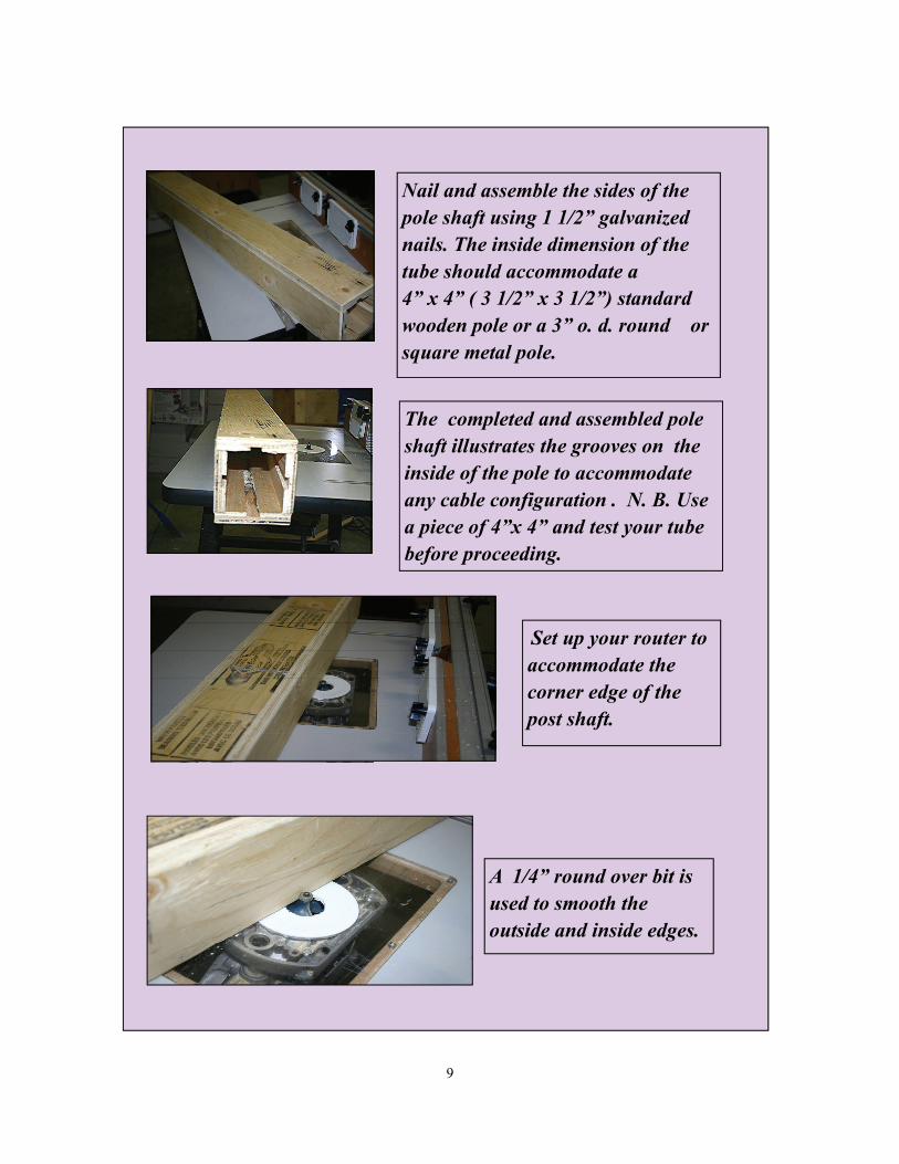
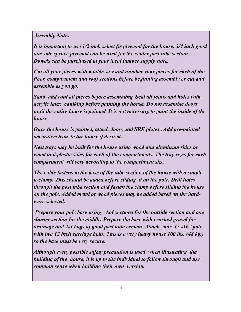
Nail and assemble the sides of the pole shaft using 1 1/2” galvanized nails. The inside dimension of the tube should accommodate a 4” x 4” ( 3 1/2” x 3 1/2”) standard wooden pole or a 3” o. d. round or square metal pole.
The completed and assembled pole shaft illustrates the grooves on the inside of the pole to accommodate any cable configuration . N. B. Use a piece of 4”x 4” and test your tube before proceeding.
Set up your router to accommodate the corner edge of the post shaft.
A 1/4” round over bit is used to smooth the outside and inside edges.
9
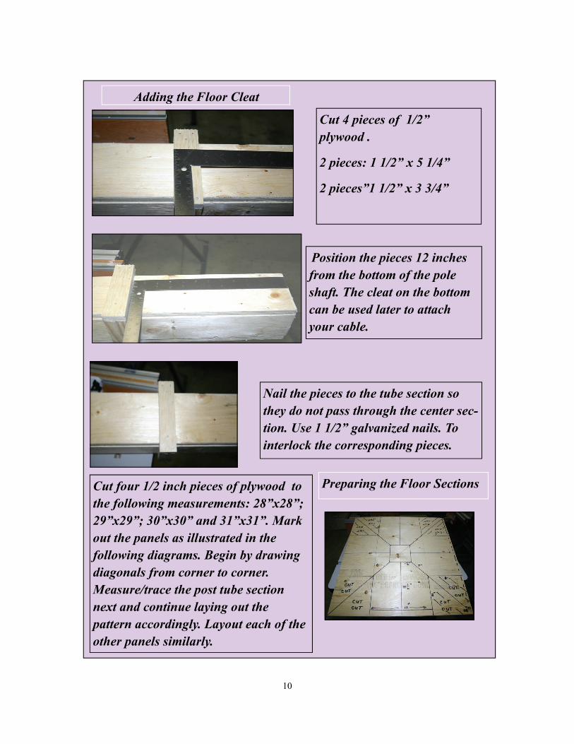
Cut 4 pieces of 1/2” plywood .
2 pieces: 1 1/2” x 5 1/4”
2 pieces”1 1/2” x 3 3/4”
Position the pieces 12 inches from the bottom of the pole shaft. The cleat on the bottom can be used later to attach your cable.
Nail the pieces to the tube section so they do not pass through the center sec-tion. Use 1 1/2” galvanized nails. To interlock the corresponding pieces.
Cut four 1/2 inch pieces of plywood to the following measurements: 28”x28”; 29”x29”; 30”x30” and 31”x31”. Mark out the panels as illustrated in the following diagrams. Begin by drawing diagonals from corner to corner. Measure/trace the post tube section next and continue laying out the pattern accordingly. Layout each of the other panels similarly.
Adding the Floor Cleat
Preparing the Floor Sections
10
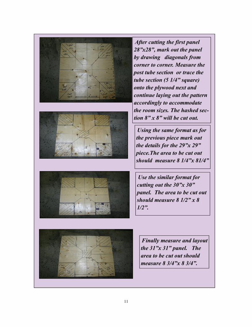
After cutting the first panel 28”x28”, mark out the panel by drawing diagonals from corner to corner. Measure the post tube section or trace the tube section (5 1/4” square) onto the plywood next and continue laying out the pattern accordingly to accommodate the room sizes. The hashed sec-tion 8” x 8” will be cut out.
Using the same format as for the previous piece mark out the details for the 29”x 29” piece.The area to be cut out should measure 8 1/4”x 81/4”
Use the similar format for cutting out the 30”x 30” panel. The area to be cut out should measure 8 1/2” x 8 1/2”.
Finally measure and layout the 31”x 31” panel. The area to be cut out should measure 8 3/4”x 8 3/4”.
11

Construct a jig using a piece of 1/2 inch plywood and pine stock 3/4 “ x 1”. This will be used to mark out the corners of the second and third floors after removing excess material.
On all plywood remove each of the corner sections as marked. Once the fence on the table saw is fixed at the correct measure-ment i.e.8” then all corners can be removed exactly. Make a sin-gle cut first measuring 8”.
Turn the plywood piece over and make another 8” cut. Repeat the process until all corners are removed.
The photo illustrates all the pieces and how the corner pieces have been removed.
Cutting the Floor Sections
12
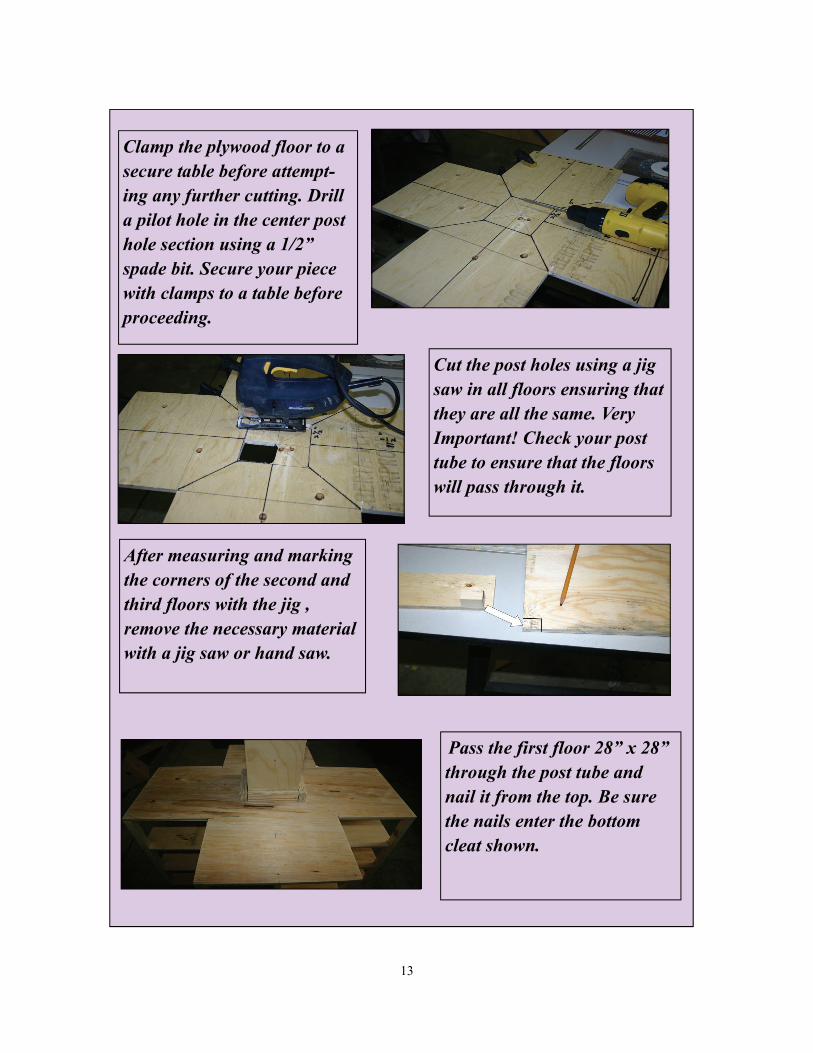
Clamp the plywood floor to a secure table before attempt-ing any further cutting. Drill a pilot hole in the center post hole section using a 1/2” spade bit. Secure your piece with clamps to a table before proceeding.
Cut the post holes using a jig saw in all floors ensuring that they are all the same. Very Important! Check your post tube to ensure that the floors will pass through it.
After measuring and marking the corners of the second and third floors with the jig , remove the necessary material with a jig saw or hand saw.
Pass the first floor 28” x 28” through the post tube and nail it from the top. Be sure the nails enter the bottom cleat shown.
13
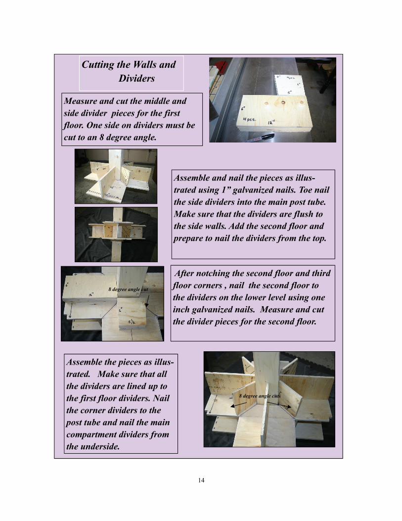
Measure and cut the middle and side divider pieces for the first floor. One side on dividers must be cut to an 8 degree angle.
Assemble and nail the pieces as illus-trated using 1” galvanized nails. Toe nail the side dividers into the main post tube. Make sure that the dividers are flush to the side walls. Add the second floor and prepare to nail the dividers from the top.
After notching the second floor and third floor corners , nail the second floor to the dividers on the lower level using one inch galvanized nails. Measure and cut the divider pieces for the second floor.
Assemble the pieces as illus-trated. Make sure that all the dividers are lined up to the first floor dividers. Nail the corner dividers to the post tube and nail the main compartment dividers from the underside.
Cutting the Walls and Dividers
8 degree angle cut
8 degree angle cuts
14
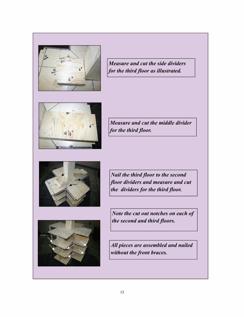
Measure and cut the side dividers for the third floor as illustrated.
Measure and cut the middle divider for the third floor.
Nail the third floor to the second floor dividers and measure and cut the dividers for the third floor.
All pieces are assembled and nailed without the front braces.
Note the cut out notches on each of the second and third floors.
15

The dividers should be positioned so they do not interfere with the installation of the side walls. They should be set flush to the floor edge.
Measure and cut 8 pieces of 3/4” x 1” x 19 ” pine for the front door faces. Angle cut the top and bottom of the pieces to fit the floors flush.
Nail the braces to the front of each section of the house from the top and bottom as well as to each individual floor with 1” galvanized nails. The previous cut out slots on the second and third floor may be adjusted to accommodate the brace angle.
Enough space has been allowed for the room dividers between floors to nail the partitions from the bottom .
16

Mark the center of the post tube on all sides using a square.
Draw a line to the base of the top floor.
Measure and mark 10 “from the base to the top of the pole.
Cut two pieces of 1/2” plywood to the dimensions illustrated. These will be used to support the roof and to act as dividers for the upper floor.
17

Using the larger triangular section, mark the walls on the center post on all four sides.
Cut two small triangle pieces as
illustrated.
Install these smaller pieces at the indicated mark using 1 1/4 ‘ dry wall screws. Angle the screws so they do not protrude inside the post hole section.
Install the two larger triangles similarly on opposite sides of the post tube .
18
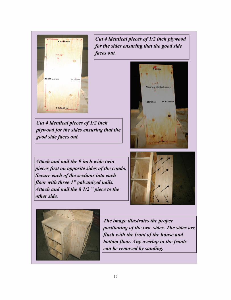
Cut 4 identical pieces of 1/2 inch plywood for the sides ensuring that the good side faces out.
Cut 4 identical pieces of 1/2 inch plywood for the sides ensuring that the good side faces out.
Attach and nail the 9 inch wide twin pieces first on opposite sides of the condo. Secure each of the sections into each floor with three 1” galvanized nails. Attach and nail the 8 1/2 ” piece to the other side.
The image illustrates the proper positioning of the two sides. The sides are flush with the front of the house and bottom floor. Any overlap in the fronts can be removed by sanding.
19

Cut and preassemble the following pairs of dividers and roof panels. These will be used just below the roof section. The upper piece in the photo will be angled cut at a 45 degree angle to accommodate the roof slope.
Nail and assemble the pair of roof section dividers after cutting to di-mensions.
These pair of roof sections will be attached to the section with the larger roof gables. ( larger triangle wood section).
Measure and cut 2 pieces as illustrated . These will be attached to a room divider and then to the smaller roof gable side of the roof.
45 degree cuts
Measure and cut out piece on the end approx. 1/2 x1 1/2 ” to fit between larger and smaller triangle gables.
20

The illustration indicates how the roof , the larger roof gable, and the roof section are finally assembled.
Nail all the roof sections and the dividers to the roof gables and floors.
Cut four pieces according to the following illustration. Angle cut the top section at 45 degrees. Ensure that the good side of the plywood is facing outward.
Similarly, cut four pieces according to the following illustration. Angle cut the top section at 45 degrees. Ensure that the good side of the plywood is facing outward.
Proper positioning of piece between two end gables.
21

Countersink, pre-drill and screw the first roof section to the larger gable as illustrated. One screw will hold it in place until the other roof side is attached. Assemble the roof on the opposite side as well.
Fasten the roof section into the upper room roof panel from the side.
The pair of roof sections has been assembled. Note how the bottom section of the roof slips over the side section.
The two larger gable opposite roof sides have now been assembled and fit neatly into the wall sides. Proceed to the next smaller roof sections and assemble accordingly.
22

Note how the two roof valleys are assembled. A bead of caulk can be added around the post tube and roof valley to prevent water from entering the house.
Close up detail of the roof sections. If these sections do not align, scribe and angle cut the roof section until it meets the other correctly.
The upper gable floor section has been secured with deck screws.
Fasten the roof section to the side wall into the upper floor section from each side with deck screws.
23

Upper completed compartments with walls and roof fastened into position.
The pole cap is constructed of 3/4 “ material and consists of four sec-tions and a cap. Mark and cut out two pieces as illustrated.
Mark and cut out two opposite side pieces as illustrated and angle cut the bottom to accommodate the roof sections. The roof cap length can be adjusted to suit your individual pole and pulley configuration. A good test is to take a piece of pole and pulley assembly and test the cap for proper fit.
Attach the roof cap with four deck screws and rout the sides.
Preparing the Pole Cap
24

Make four roof ridge caps from an 8 ’ x 1” x 2” inch pine piece. Each piece should measure 24 ” long .
Set your saw on a 45 degree angle and run your pine to form a 45 degree v-groove on the bottom of each piece.
The completed v-groove will fit neatly on the completed roof section.
Contour cut the end of the pine piece to allow for some architectural variance using a jig or band saw.
Preparing the Roof Ridge Caps
25

A router can be used to round over the top edges and shape the end piece.
The roof ridge has been prepared for final installation.
Countersink and drill three holes in the ridge cap. Position the ridge cap to allow at least 1/4 inch clearance for the post cap.
Roof ridge has been fastened into position with post cap in place.
Attaching the Roof Ridge
26
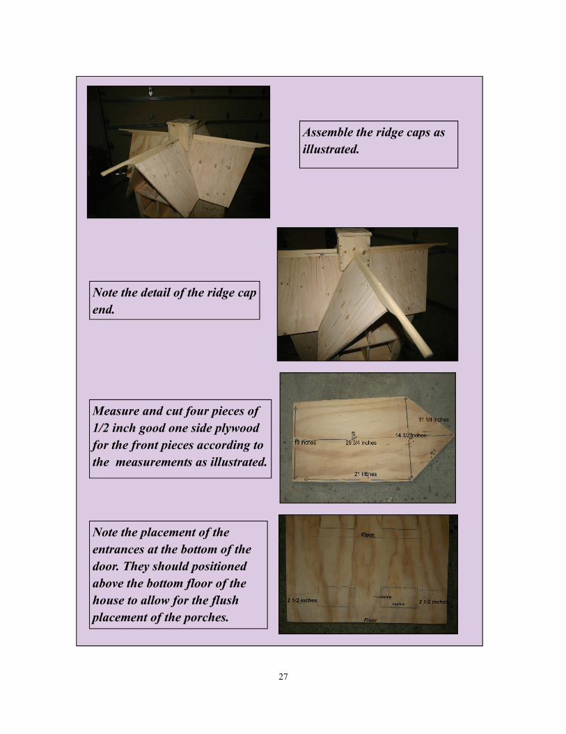
Assemble the ridge caps as illustrated.
Note the detail of the ridge cap end.
Measure and cut four pieces of 1/2 inch good one side plywood for the front pieces according to the measurements as illustrated.
Note the placement of the entrances at the bottom of the door. They should positioned above the bottom floor of the house to allow for the flush placement of the porches.
27
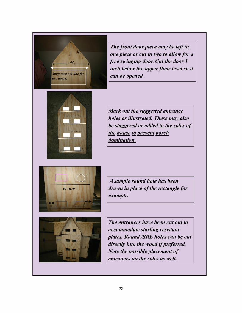
The front door piece may be left in one piece or cut in two to allow for a free swinging door. Cut the door 1 inch below the upper floor level so it can be opened.
Mark out the suggested entrance holes as illustrated. These may also be staggered or added to the sides of the house to prevent porch domination.
A sample round hole has been drawn in place of the rectangle for example.
The entrances have been cut out to accommodate starling resistant plates. Round /SRE holes can be cut directly into the wood if preferred. Note the possible placement of entrances on the sides as well.
FLOOR
Suggested cut line for two doors.
28

Cut out 16 discs using a 5 inch hole cutter from 1/2 inch stock.
(Plywood or Pine)
Sand the face and edges of the disks. The completed sanded disk is shown with the wood grain running vertically along the plain.
Rout the edge of all the disks with a 1/4 inch round over bit.
Cut these disks in half along the wood grain. Safety warning: Secure the top of the disk with a holding de-vice to prevent kick back. A band saw may also be used to achieve the same results.
29

Measure and screw the disks to each of the front pieces allowing a 1/8”- 1 ” space below the entrance hole. If starling resistant plates will be used the porches should be placed as close to flush with the hole as possible but 1/4”- 1/2” is often recommended.
Porches are mounted slightly staggered to avoid porch domination .
Assemble all the porches on each of the sides. Add molding or trim work to the roof sides.
Here is a possible entrance and no porch scenario with purchased clinger entrances. The front pieces are temporarily attached to the house for clarity. The front pieces can be attached with screws or with hinges once the entire house is painted. This set of entrances do not require a porch.
30

The Victorian fretwork bracket is comprised of three pieces- the bracket and two pieces of supporting 1/2 inch plywood. Cut out your bracket from 2 inch MDF or pine. Rout the pieces to create a smooth edge before assembling and painting. Cut out the plywood pieces as indicated.
Attach the plywood pieces to the fretwork centering them to create an esthetic look.
The fretwork is now assembled and ready for painting. Adjust your fretwork to the bottom plate of the house before assembling. Do not attach the fretwork until your house is mounted on the pole.
The completed fretwork can be sanded, primed and painted before attaching it to the martin house later.
31

The fretwork bracket can be added before or after painting the house with eight deck screws. It is easier to mount the house on the pole without the fretwork.
Mast assembly pieces are con-structed from two pieces of 1/2 inch plywood:
5 1/2 inch x 5 1/2 inch and 4 1/2 inch x 4 1/2 inch.
Assemble the two pieces with drywall screws and drill a 5/8 inch hole in the center to center the mast pole dowel. Rout the edges of each piece.
Construct the mast from pine. The measurements of the center mast are 2”x 2” x 36”. Rout the edges of the mast with a round over bit. Drill 5/8 inch holes on opposite sides of the mast at 6 inch intervals.
32

The dowel pieces have been glued and a brad nail used for each perch to secure it to the mast..
Measure, drill and glue a 5/8 ” dowel into the mast to pass through the mast base and pole cap.
The mast piece may be attached with four drywall screws. The com-pleted mast head is ready to be sanded and painted.
The completed mast head gives the top of the house some architectural balance to which the martin decoy silhouettes can be later attached.
33

Using a template trace the image on a piece of galvanized metal sheet or aluminum. Use a punch to detail the eyes.
Using metal shears cut out the silhouette. File and sand the rough edges.
Rough up the metal with steel wool and prime the metal before adding your final exterior paint.
Use your imagination to design more purple martin silhouettes. Cut out feather detail and bend and shape your martin. Drill a small hole in the martin to attach to the perch.
Purple Martin Silhouettes
34

Apply a good heat reflecting light exterior tinted paint primer and two finish coats . Attach doors and clinger , WDC, round or crescent plate entrances to your house after painting with screws.
As an option the front doors may also be left in one piece and attached with four deck screws or installed so that there are two door sections without hinges. In this photo, the bottom and top pieces have been cut and the bottom portion is secured with two 3 inch non mortised (bi-fold) hinges. They are positioned 3” from the top and bottom of the door. The upper door section is held in place with two screws for easy access and cleanout.
Install two hook and eyes per door as illustrated 3” below the top of the door and 3” above the door bottom .
Paint, Hardware , Nest Trays
Prepare some nest trays with straw and mud for your martin compartments. These can be made in a variety of styles and configurations. Do drill some drainage holes at the bottom of the tray.
35

Install pole base and attach winch to post with two 3/8 ” x 4” bolts ,washers and lock nuts. Attach 40 feet of 3/8” galvanized aircraft cable to the winch.
Attach the post cap to the end of the post with 4 deck screws . Similarly, attach mast head with silhouettes to post cap with 4 deck screws .
Slide the house on the pole and slide the cable through the slot in the post tube over the pulley and secure the end to the bottom of the house. Have someone help you!
Lower the martin house so it is at its lowest level and then slowly raise the martin house into position. Make sure the pulley is turning at the top of the pole. Do not raise the house too high to bind the pulley and lift off the post cap!
36

Plug the holes with foam to prevent any unwanted birds from entering until the martins arrive.
When the house is fully extended , make sure that the safety bolt is in place and that the winch is secured with a lock and chain.
Test the martin house to see that it raises and lowers without binding. Install a safety bolt at least 6 inches above the main operators head level .
N.B. The winch should be locked so no one can tamper with the house set up.
37
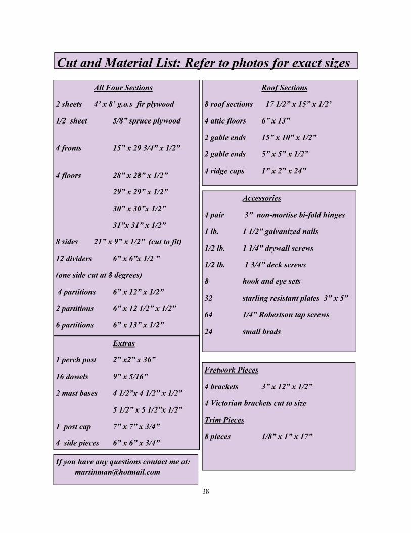
All Four Sections
2 sheets 4’ x 8’ g.o.s fir plywood
1/2 sheet 5/8” spruce plywood
4 fronts 15” x 29 3/4” x 1/2”
4 floors 28” x 28” x 1/2”
29” x 29” x 1/2”
30” x 30”x 1/2”
31”x 31” x 1/2”
8 sides 21” x 9” x 1/2” (cut to fit)
12 dividers 6” x 6”x 1/2 ”
(one side cut at 8 degrees)
4 partitions 6” x 12” x 1/2”
2 partitions 6” x 12 1/2” x 1/2”
6 partitions 6” x 13” x 1/2”
Roof Sections
8 roof sections 17 1/2” x 15” x 1/2’
4 attic floors 6” x 13”
2 gable ends 15” x 10” x 1/2”
2 gable ends 5” x 5” x 1/2”
4 ridge caps 1” x 2” x 24”
Cut and Material List: Refer to photos for exact sizes
Extras
1 perch post 2” x2” x 36”
16 dowels 9” x 5/16”
2 mast bases 4 1/2”x 4 1/2” x 1/2”
5 1/2” x 5 1/2”x 1/2”
1 post cap 7” x 7” x 3/4”
4 side pieces 6” x 6” x 3/4”
Accessories
4 pair 3” non-mortise bi-fold hinges
1 lb. 1 1/2” galvanized nails
1/2 lb. 1 1/4” drywall screws
1/2 lb. 1 3/4” deck screws
8 hook and eye sets
32 starling resistant plates 3” x 5”
64 1/4” Robertson tap screws
24 small brads
Fretwork Pieces
4 brackets 3” x 12” x 1/2”
4 Victorian brackets cut to size
Trim Pieces
8 pieces 1/8” x 1” x 17”
38
If you have any questions contact me at: [email protected]

Taverner Pole Mounting Kit
1 (brake) winch
40’ 3/8” galvanized aircraft cable
1 3 1/2” pulley
1 4 ” x 1/2 ” bolt, washer and nut
1 safety bolt 1/2” x 6”
1 U –bolt for sleeve
1 cable eye
2 cable clips
1 cable nipple end for winch
2 12” x 1/2” carriage bolts, nuts, washers
1 lock
1 12 ” chain
1 predator proof guard (optional)
Caution
Always insert the safety bolt into the pole just above head level to avoid injury!
Kid Proof Your Martin Site
Never leave the winch like this! Secure it with a lock and chain!
39
Post Requirements
1 15’ x 4” x 4”
1 15’ x 4” x 4” cut in three for post base
1 Taverner mounting kit
3 (33Kg/ 66 lb. bag) post hole cement
Proper post installation :Three feet is placed in ground and three feet above. Post base is secured with two carriage bolts.
Winch attached to pole with two carriage bolts.