Balboa's BP Troubleshooting & Service Manual€¦ · manufactured by Balboa Water Group. Balboa...
88
42211 C Balboa's BP Troubleshooting & Service Manual 6 0 Hz SPA CONTROL SYSTEMS PANELS BP500 BP2000G1 TP900, TP800, TP600, TP400 THIS MANUAL COVERS THE FOLLOWING:
Transcript of Balboa's BP Troubleshooting & Service Manual€¦ · manufactured by Balboa Water Group. Balboa...

1Manufactured under one or more of these patents. U.S. Patents: 5332944, 5361215, 5550753, 5559720, 5,883,459, 6253227, 6282370, 6590188, 6976052, 6965815, 7030343, 7,417, 834 b2,
Canadian Patent: 2342614, Australian patent: 2373248 other patents both foreign and domestic applied for and pending. All material copyright of Balboa Water Group.42211 C
Balboa's BP Troubleshooting & Service Manual
60 HzSPA CONTROL SYSTEMS PANELS
BP500 BP2000G1
TP900, TP800, TP600, TP400
THIS MANUAL COVERS THE FOLLOWING:
2 Manufactured under one or more of these patents. U.S. Patents: 5332944, 5361215, 5550753, 5559720, 5,883,459, 6253227, 6282370, 6590188, 6976052, 6965815, 7030343, 7,417, 834 b2, Canadian Patent: 2342614, Australian patent: 2373248 other patents both foreign and domestic applied for and pending. All material copyright of Balboa Water Group. 6/22/13
© 2013 Balboa Water Group. All Rights Reserved.
Introduction
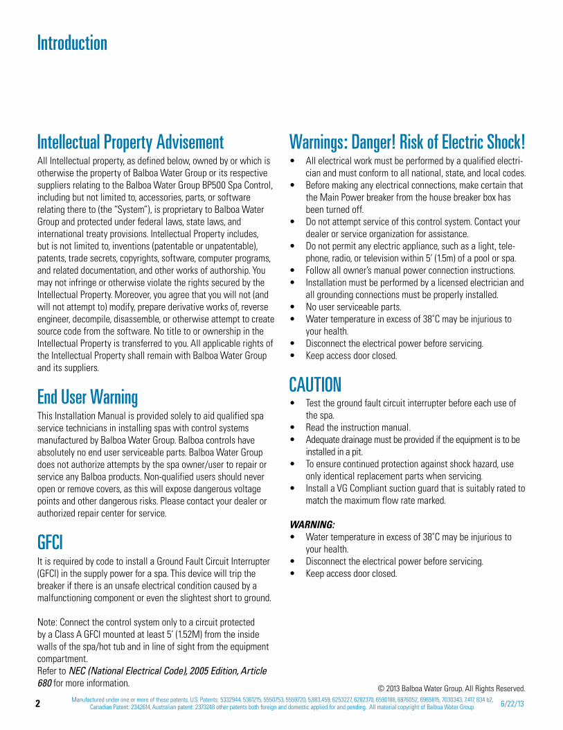
Intellectual Property AdvisementAll Intellectual property, as defined below, owned by or which is otherwise the property of Balboa Water Group or its respective suppliers relating to the Balboa Water Group BP500 Spa Control, including but not limited to, accessories, parts, or software relating there to (the “System”), is proprietary to Balboa Water Group and protected under federal laws, state laws, and international treaty provisions. Intellectual Property includes, but is not limited to, inventions (patentable or unpatentable), patents, trade secrets, copyrights, software, computer programs, and related documentation, and other works of authorship. You may not infringe or otherwise violate the rights secured by the Intellectual Property. Moreover, you agree that you will not (and will not attempt to) modify, prepare derivative works of, reverse engineer, decompile, disassemble, or otherwise attempt to create source code from the software. No title to or ownership in the Intellectual Property is transferred to you. All applicable rights of the Intellectual Property shall remain with Balboa Water Group and its suppliers.
End User WarningThis Installation Manual is provided solely to aid qualified spa service technicians in installing spas with control systems manufactured by Balboa Water Group. Balboa controls have absolutely no end user serviceable parts. Balboa Water Group does not authorize attempts by the spa owner/user to repair or service any Balboa products. Non-qualified users should never open or remove covers, as this will expose dangerous voltage points and other dangerous risks. Please contact your dealer or authorized repair center for service.
GFCIIt is required by code to install a Ground Fault Circuit Interrupter (GFCI) in the supply power for a spa. This device will trip the breaker if there is an unsafe electrical condition caused by a malfunctioning component or even the slightest short to ground.
Note: Connect the control system only to a circuit protected by a Class A GFCI mounted at least 5’ (1.52M) from the inside walls of the spa/hot tub and in line of sight from the equipment compartment. Refer to NEC (National Electrical Code), 2005 Edition, Article 680 for more information.
Warnings: Danger! Risk of Electric Shock! All electrical work must be performed by a qualified electri-cian and must conform to all national, state, and local codes.Before making any electrical connections, make certain that the Main Power breaker from the house breaker box has been turned off.Do not attempt service of this control system. Contact your dealer or service organization for assistance. Do not permit any electric appliance, such as a light, tele-phone, radio, or television within 5’ (1.5m) of a pool or spa.Follow all owner’s manual power connection instructions.Installation must be performed by a licensed electrician and all grounding connections must be properly installed. No user serviceable parts.Water temperature in excess of 38˚C may be injurious to your health.Disconnect the electrical power before servicing.Keep access door closed.
CAUTIONTest the ground fault circuit interrupter before each use of the spa.Read the instruction manual.Adequate drainage must be provided if the equipment is to be installed in a pit.To ensure continued protection against shock hazard, use only identical replacement parts when servicing.Install a VG Compliant suction guard that is suitably rated to match the maximum flow rate marked.
WARNING:Water temperature in excess of 38˚C may be injurious to your health.Disconnect the electrical power before servicing.Keep access door closed.
3Manufactured under one or more of these patents. U.S. Patents: 5332944, 5361215, 5550753, 5559720, 5,883,459, 6253227, 6282370, 6590188, 6976052, 6965815, 7030343, 7,417, 834 b2,
Canadian Patent: 2342614, Australian patent: 2373248 other patents both foreign and domestic applied for and pending. All material copyright of Balboa Water Group.42211 C
Codes and ComplianceAll of the electrical wiring methods and materials used to complete the electrical installation of the BP control systems must be in accordance with the National Electrical Code or the Canadian Electric Code, as well as any local electrical codes in effect at the time of installation.
The selection of electrical materials required to accomplish this installation and the installation of the control system must be made by, or be under the direct supervision of, a qualified electrician.
The systems herein are classified as a “continuous duty appliance” and is intended primarily for installation at a single family dwelling. The installation recommendations and instructions contained in this manual are directed solely toward these issues.
WARNING!If there is any doubt whether the system that you are repairing does not have these features, contact a licensed, qualified electrician. Do not attempt to modify the wiring yourself.

4 Manufactured under one or more of these patents. U.S. Patents: 5332944, 5361215, 5550753, 5559720, 5,883,459, 6253227, 6282370, 6590188, 6976052, 6965815, 7030343, 7,417, 834 b2, Canadian Patent: 2342614, Australian patent: 2373248 other patents both foreign and domestic applied for and pending. All material copyright of Balboa Water Group. 6/22/13
Basic Installation and Confi guration Guidelines Use minimum 6AWG copper conductors only.
Torque fi eld connections between 21 and 23 in lbs.
Readily accessible disconnecting means to be provided at time of instal-lation.
Permanently connected.
Connect only to a circuit protected by a Class A Ground Fault Circuit Interrupter (GFCI) or Residual Current Device (RCD) mounted at least 5’ (1.52M) from the inside walls of the spa/hot tub and in line of sight from the equipment compartment.
CSA enclosure: Type 2
Refer to Wiring Diagram inside the cover of the control enclosure.
Refer to Installation and Safety Instructions provided by the spa manufac-turer.
Warning: People with infectious diseases should not use a spa or hot tub.
Warning: To avoid injury, exercise care when entering or exiting the spa or hot tub.
Warning: Do not use a spa or hot tub immediately following strenuous exercise
Warning: Prolonged immersion in a spa or hot tub may be injurious to your health
Warning: Maintain water chemistry in accordance with the Manufactur-ers instructions.
Warning: The equipment and controls shall be located not less than 1.5
meters horizontally from the spa or hot tub.
Warning! GFCI or RCD Protection.The Owner should test and reset the GFCI or RCD on a regular basis to verify its function.
CSA Compliance/ConformitéCaution:
idual current device before each use of the spa.
in a pit.
interrupter or residual current device.
replacement parts when servicing.
ow rate
Warning:
Attention:
er l’effi cacite du disjoncteur differentiel avant d’utiliser differentiel avant d’utiliser le bain.
drainage adequat.
tiel de Class A.
electrique, lors de l’entretien employer seulement des pieces de rechange identiques.
debit maximal indique.
Avertissement:
danger pour la sante.
Warning/Advertissement:
Garder la porte fermer.
Warning! Qualifi ed Technician Required for Service and Installation
Warning! Shock Hazard! No User Serviceable Parts.Do not attempt service of this control system. Contact your dealer or service organization for assistance. Follow all owner’s manual power connection instructions. Installation must be performed by a licensed electrician and all ground-ing connections must be properly installed.
5Manufactured under one or more of these patents. U.S. Patents: 5332944, 5361215, 5550753, 5559720, 5,883,459, 6253227, 6282370, 6590188, 6976052, 6965815, 7030343, 7,417, 834 b2,
Canadian Patent: 2342614, Australian patent: 2373248 other patents both foreign and domestic applied for and pending. All material copyright of Balboa Water Group.42211 C
Table of Contents
Introduction . . . . . . . . . . . . . . . . . . . . . . . . . . . . . . . . . . . . . . . . 2Intellectual Property Advisement . . . . . . . . . . . . . . . . . . . . . . . . . . . . . . . . . . 2End User Warning . . . . . . . . . . . . . . . . . . . . . . . . . . . . . . . . . . . . . . . . . 2GFCI . . . . . . . . . . . . . . . . . . . . . . . . . . . . . . . . . . . . . . . . . . . . . . . 2Warnings: Danger! Risk of Electric Shock! . . . . . . . . . . . . . . . . . . . . . . . . . . . . . . 2Codes and Compliance . . . . . . . . . . . . . . . . . . . . . . . . . . . . . . . . . . . . . . . 3
Service Tools and Parts Checklist . . . . . . . . . . . . . . . . . . . . . . . . . . . . . . 7TP Panel Overview and User Guides . . . . . . . . . . . . . . . . . . . . . . . . . . . . . . . . . 8Product Identification . . . . . . . . . . . . . . . . . . . . . . . . . . . . . . . . . . . . . . . 9
General Troubleshooting & Servicing of Spa's Electrical Equipment . . . . . . . . . . . . . . . 10G.F.C.I. Troubleshooting . . . . . . . . . . . . . . . . . . . . . . . . . . . . . . . . . . . . . 11120 Volt Residential Wiring Schematic with G.F.C.I. . . . . . . . . . . . . . . . . . . . . . . . . . 12240 Volt Residential Wiring Schematic with G.F.C.I. . . . . . . . . . . . . . . . . . . . . . . . . . 14Voltage Checks: Breaker Box, G.F.C.I. & System Box . . . . . . . . . . . . . . . . . . . . . . . . . 16Wiring Checks . . . . . . . . . . . . . . . . . . . . . . . . . . . . . . . . . . . . . . . . . 17Testing a System with Power . . . . . . . . . . . . . . . . . . . . . . . . . . . . . . . . . . . 18Troubleshooting Pumps, Problem & Cause . . . . . . . . . . . . . . . . . . . . . . . . . . . . . 22Acceptable Ranges for Testing Equipment . . . . . . . . . . . . . . . . . . . . . . . . . . . . . 23Fuses: Devices, Locations, and Values . . . . . . . . . . . . . . . . . . . . . . . . . . . . . . . 24
BP 60Hz Spa Control System Wiring Diagrams . . . . . . . . . . . . . . . . . . . . . . . . . 25Wiring Diagram - BP500, Part Number 56278, Setup No. 1 (as manufactured) . . . . . . . . . . . . . . 25Wiring Diagram - BP2000G1, Part Number 56377 . . . . . . . . . . . . . . . . . . . . . . . . . . . 26Wiring Diagram - BP2000G1, Part Number 56377-01 . . . . . . . . . . . . . . . . . . . . . . . . . 28Wiring Diagram - BP20MSSH, Part Number: 56373 (MicroSilk) . . . . . . . . . . . . . . . . . . . . 30
Troubleshooting Using Resistance . . . . . . . . . . . . . . . . . . . . . . . . . . . . . . 32Ohm’s Law . . . . . . . . . . . . . . . . . . . . . . . . . . . . . . . . . . . . . . . . . . . 32Testing a Fuse: Continuity . . . . . . . . . . . . . . . . . . . . . . . . . . . . . . . . . . . . 33Troubleshooting Heater Resistance . . . . . . . . . . . . . . . . . . . . . . . . . . . . . . . . 34Troubleshooting Heater Posts Resistance to Heater Housing . . . . . . . . . . . . . . . . . . . . . 35
Troubleshooting with Voltage . . . . . . . . . . . . . . . . . . . . . . . . . . . . . . . . 36Verifying Incoming Voltage at the Terminal Block - BP500, BP2000G1 . . . . . . . . . . . . . . . . . 37Testing Pump Fuses for Damage with Voltage On - BP2000G1 . . . . . . . . . . . . . . . . . . . . 38Testing Heater Voltage - All BP Systems . . . . . . . . . . . . . . . . . . . . . . . . . . . . . . 39A Safer Way to Test Heater Voltages . . . . . . . . . . . . . . . . . . . . . . . . . . . . . . . 40Testing Pump Fuses for Damage with Voltage On - BP500 . . . . . . . . . . . . . . . . . . . . . . 41Testing Heater Amperage . . . . . . . . . . . . . . . . . . . . . . . . . . . . . . . . . . . . 42Testing Low Speed and High Speed at the AMP Pump Connector . . . . . . . . . . . . . . . . . . . 43
6 Manufactured under one or more of these patents. U.S. Patents: 5332944, 5361215, 5550753, 5559720, 5,883,459, 6253227, 6282370, 6590188, 6976052, 6965815, 7030343, 7,417, 834 b2, Canadian Patent: 2342614, Australian patent: 2373248 other patents both foreign and domestic applied for and pending. All material copyright of Balboa Water Group. 6/22/13
Component Failure and Replacement Testing . . . . . . . . . . . . . . . . . . . . . . . . . 44Software Setups and Test Mode . . . . . . . . . . . . . . . . . . . . . . . . . . . . . . . . . 44Setup Changes with DIP Switch 1 ON - BP500 . . . . . . . . . . . . . . . . . . . . . . . . . . . . 45Setup Changes with DIP Switch 1 ON - BP2500 . . . . . . . . . . . . . . . . . . . . . . . . . . . 47Testing the Sensor Set . . . . . . . . . . . . . . . . . . . . . . . . . . . . . . . . . . . . . . 48Remove and Replace a System Circuit Board . . . . . . . . . . . . . . . . . . . . . . . . . . . . 50Removing the Heater Assembly from a BP Spa System . . . . . . . . . . . . . . . . . . . . . . . . 52
TP800, TP900 Panel Operations . . . . . . . . . . . . . . . . . . . . . . . . . . . . . . . 54The Main Screen - Navigation . . . . . . . . . . . . . . . . . . . . . . . . . . . . . . . . . . 54TP800, TP900 Priming Mode Start-up Sequence . . . . . . . . . . . . . . . . . . . . . . . . . . . 55TP800, TP900 Spa Behavior . . . . . . . . . . . . . . . . . . . . . . . . . . . . . . . . . . . . 56TP800, TP900 Adjusting Filtration . . . . . . . . . . . . . . . . . . . . . . . . . . . . . . . . . 57TP800, TP900 Panel Lock & Unlock . . . . . . . . . . . . . . . . . . . . . . . . . . . . . . . . . 58TP800, TP900 Sensor and System Related Messages . . . . . . . . . . . . . . . . . . . . . . . . . 59TP800, TP900 Utilities Menu . . . . . . . . . . . . . . . . . . . . . . . . . . . . . . . . . . . . 63
TP400, TP600 Standard Panel Operations . . . . . . . . . . . . . . . . . . . . . . . . . . . 64Main Screen - Navigation . . . . . . . . . . . . . . . . . . . . . . . . . . . . . . . . . . . . 64TP400, TP600 Panel Utilities Menu . . . . . . . . . . . . . . . . . . . . . . . . . . . . . . . . . 65TP400, TP600 Preparation and Priming . . . . . . . . . . . . . . . . . . . . . . . . . . . . . . . 66TP400, TP600 Message Codes . . . . . . . . . . . . . . . . . . . . . . . . . . . . . . . . . . . 67TP400, TP600 Utilities Fault Log Menu . . . . . . . . . . . . . . . . . . . . . . . . . . . . . . . 70TP400, TP600 Utilities Menu - GFCI Test Feature . . . . . . . . . . . . . . . . . . . . . . . . . . . 71TP400, TP600 Simplified vs. Standard Panel Operations . . . . . . . . . . . . . . . . . . . . . . . . 72A Simplified Main Menu (Doc No. 42185B) . . . . . . . . . . . . . . . . . . . . . . . . . . . . . 73
Supplemental Information . . . . . . . . . . . . . . . . . . . . . . . . . . . . . . . . . . 74Optional Balboa DolphinTM Remote . . . . . . . . . . . . . . . . . . . . . . . . . . . . . . . . . 74Spa Guidelines to Keep in Mind . . . . . . . . . . . . . . . . . . . . . . . . . . . . . . . . . . 76Glossary . . . . . . . . . . . . . . . . . . . . . . . . . . . . . . . . . . . . . . . . . . . . 77
Index . . . . . . . . . . . . . . . . . . . . . . . . . . . . . . . . . . . . . . . . . . . 78
Index of Paragraph Topics . . . . . . . . . . . . . . . . . . . . . . . . . . . . . . . . . 83

7Manufactured under one or more of these patents. U.S. Patents: 5332944, 5361215, 5550753, 5559720, 5,883,459, 6253227, 6282370, 6590188, 6976052, 6965815, 7030343, 7,417, 834 b2,
Canadian Patent: 2342614, Australian patent: 2373248 other patents both foreign and domestic applied for and pending. All material copyright of Balboa Water Group.42211 C
Service Tools and Parts Checklist
SERVICE TOOLS REQUIREDAmmeter (50A) with insulated clamps for probesScrewdrivers, assorted flat and Phillips Digital Multi-meterPadlock (to lock electrical disconnect during service)Pliers: Slip Joint & Needle nose
RECOMMENDED PARTS TO HAVE FOR SERVICE CALLS
Extra Board(s)Extra Panel(s)FusesJumpersHeater AssembliesSensor Wires (No. 30344 sensor wire for example).
Logic Jumper, No. 20618
BP2000 Circuit Board
Heater Assembly
Precision Thermometer - Digital Fever TypeSilicone TubeSmall Wire Cutters3/8” and 1/4" Open End Wrenches (Heater wire nut removal)
FUSES USED ON BP SPA SYSTEMSFuse BWG Part Number
30A 30136
10A 30122
3A Slo-Blo 20600
0.3A Slo-Blo 21581
0.15A Slo-Blo 26281
0.125A Slo-Blo 26397
8 Manufactured under one or more of these patents. U.S. Patents: 5332944, 5361215, 5550753, 5559720, 5,883,459, 6253227, 6282370, 6590188, 6976052, 6965815, 7030343, 7,417, 834 b2, Canadian Patent: 2342614, Australian patent: 2373248 other patents both foreign and domestic applied for and pending. All material copyright of Balboa Water Group. 6/22/13
TP Panel Overview and User Guides
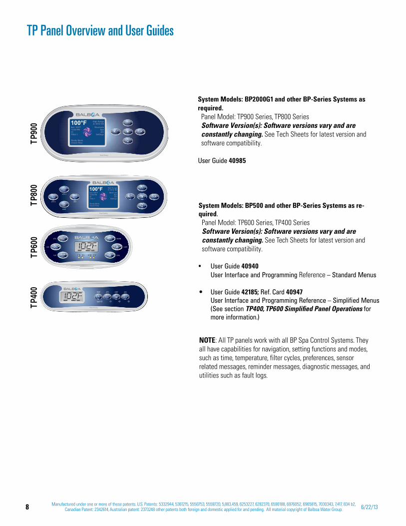
System Models: BP2000G1 and other BP-Series Systems as required. Panel Model: TP900 Series, TP800 Series Software Version(s): Software versions vary and are constantly changing. See Tech Sheets for latest version and software compatibility.
User Guide 40985
System Models: BP500 and other BP-Series Systems as re-quired. Panel Model: TP600 Series, TP400 Series Software Version(s): Software versions vary and are constantly changing. See Tech Sheets for latest version and software compatibility.
User Guide 40940 User Interface and Programming Reference – Standard Menus
User Guide 42185; Ref. Card 40947 User Interface and Programming Reference – Simplified Menus (See section TP400, TP600 Simplified Panel Operations for more information.)
NOTE: All TP panels work with all BP Spa Control Systems. They all have capabilities for navigation, setting functions and modes, such as time, temperature, filter cycles, preferences, sensor related messages, reminder messages, diagnostic messages, and utilities such as fault logs.
TP90
0TP
800
TP40
0TP
600
JETSTSS AUX LIGHT HHEATJETS AUX LIGHT HEAT
9Manufactured under one or more of these patents. U.S. Patents: 5332944, 5361215, 5550753, 5559720, 5,883,459, 6253227, 6282370, 6590188, 6976052, 6965815, 7030343, 7,417, 834 b2,
Canadian Patent: 2342614, Australian patent: 2373248 other patents both foreign and domestic applied for and pending. All material copyright of Balboa Water Group.42211 C
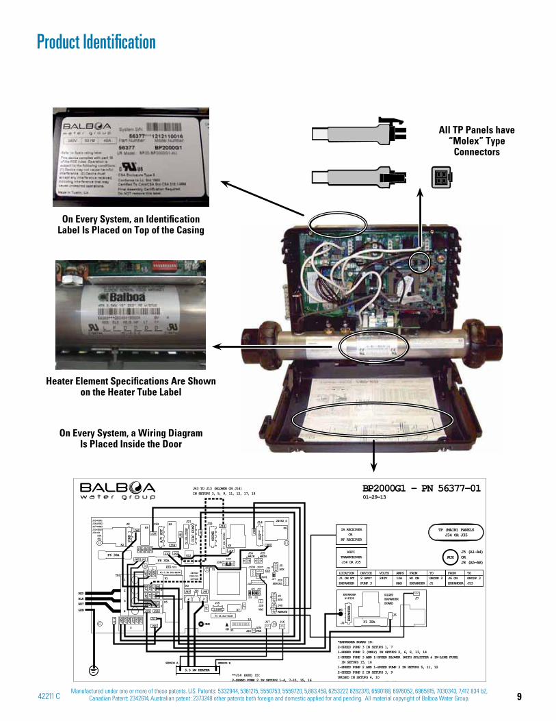
On Every System, an Identification Label Is Placed on Top of the Casing
Heater Element Specifications Are Shown on the Heater Tube Label
On Every System, a Wiring Diagram Is Placed Inside the Door
Product Identification
All TP Panels have “Molex” Type
Connectors
F4 3A SLO-BLOW
J25 J31
J26 J30
115V 115V
230V
F3 0.3A SLO-BLOW
J25=HTR1J26=HTR2J27=HTR3J30=TESTJ31=CE HTR SEL
F7 10A 250VAC
F2 10A 250VAC
J44
3
TB1
J15
ON
10
S1
K5
K1
K3
T1
K2
K4
K8
LIGHT
GND
J33J21 J32J9
1
2
3
4
2
K6
4
3
2
1
J45
J110
J79
J54
J72
J42
J3
J37
J4 J1J6
1J4
7
J77
J75
J78
J36
J60
J46J38
J39
J111
J53 J58
J11
J41
J48
J6
J7
J49
J19
J50
J13
J12
J88
J62
F6 30AF8 30A
J56
J57
J55
J59
J51
J52
J98
J10
J81 J20
J18
J43
CIRC PUMP
OZONE
A/V HOT
PUMP 1
J14K9
J5AUX
J8AUX
J40
REMOTE
J35MAIN
J34MAIN
J109
J27
J91
J22J23
SERIAL
J29VAC
J28AUXFRZ
J17 J16
24082_D
J101
J108J24
J107
K12
K7
TP (MAIN) PANELSJ34 OR J35
01-29-13BP2000G1 – PN 56377-01
AUXJ5 (A1-A4)ORJ8 (A5-A8)
GRN
WHT
REDBLK
SENSOR BSENSOR A
5.5 kW HEATER
EXPANDER
LOCATION DEVICE VOLTS AMPS FROM TO FROM TOJ1 ON RT 2 SPD* 240V 12A W1 ON GROUP 2 J6 ON GROUP 3EXPANDER PUMP 3 MAX EXPANDER J1 EXPANDER J53
*EXPANDER BOARD IS:2-SPEED PUMP 3 IN SETUPS 1, 7 1-SPEED PUMP 3 (ONLY) IN SETUPS 2, 6, 8, 13, 141-SPEED PUMP 3 AND 1-SPEED BLOWER (WITH SPLITTER & IN-LINE FUSE) IN SETUPS 15, 16 1-SPEED PUMP 2 AND 1-SPEED PUMP 3 IN SETUPS 5, 11, 122-SPEED PUMP 2 IN SETUPS 3, 9UNUSED IN SETUPS 4, 101 SPEED PUMP 2 IN SETUPS 17 18
J1
W1
J7RIGHT EXPANDERBOARD
J6
EXPANDERX-P332
F1 30A
J43 TO J13 (BLOWER ON J14) IN SETUPS 3, 5, 9, 11, 12, 17, 18
240VACCIRC/O3OPTION
AUX**
**J14 (AUX) IS:2-SPEED PUMP 2 IN SETUPS 1-4, 7-10, 15, 16
WIFITRANSCEIVERJ34 OR J35
IR RECEIVEROR
RF RECEIVER
10 Manufactured under one or more of these patents. U.S. Patents: 5332944, 5361215, 5550753, 5559720, 5,883,459, 6253227, 6282370, 6590188, 6976052, 6965815, 7030343, 7,417, 834 b2, Canadian Patent: 2342614, Australian patent: 2373248 other patents both foreign and domestic applied for and pending. All material copyright of Balboa Water Group. 6/22/13
General Troubleshooting & Servicing of Spa's Electrical Equipment
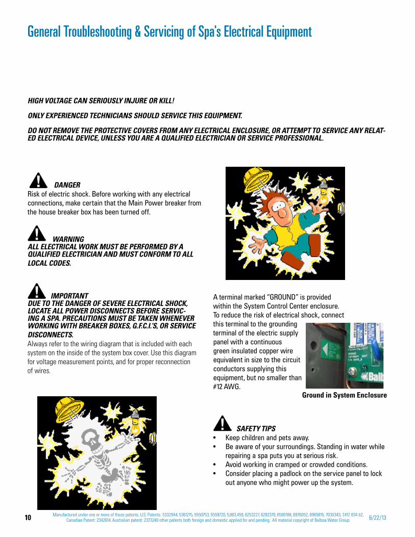
DANGER Risk of electric shock. Before working with any electrical connections, make certain that the Main Power breaker from the house breaker box has been turned off.
WARNING ALL ELECTRICAL WORK MUST BE PERFORMED BY A QUALIFIED ELECTRICIAN AND MUST CONFORM TO ALL LOCAL CODES.
IMPORTANT DUE TO THE DANGER OF SEVERE ELECTRICAL SHOCK, LOCATE ALL POWER DISCONNECTS BEFORE SERVIC-ING A SPA. PRECAUTIONS MUST BE TAKEN WHENEVER WORKING WITH BREAKER BOXES, G.F.C.I.’S, OR SERVICE DISCONNECTS.Always refer to the wiring diagram that is included with each system on the inside of the system box cover. Use this diagram for voltage measurement points, and for proper reconnection of wires.
HIGH VOLTAGE CAN SERIOUSLY INJURE OR KILL!
ONLY EXPERIENCED TECHNICIANS SHOULD SERVICE THIS EQUIPMENT.
DO NOT REMOVE THE PROTECTIVE COVERS FROM ANY ELECTRICAL ENCLOSURE, OR ATTEMPT TO SERVICE ANY RELAT-ED ELECTRICAL DEVICE, UNLESS YOU ARE A QUALIFIED ELECTRICIAN OR SERVICE PROFESSIONAL.
SAFETY TIPSKeep children and pets away.Be aware of your surroundings. Standing in water while repairing a spa puts you at serious risk.Avoid working in cramped or crowded conditions.Consider placing a padlock on the service panel to lock out anyone who might power up the system.
A terminal marked “GROUND” is provided within the System Control Center enclosure. To reduce the risk of electrical shock, connect this terminal to the grounding terminal of the electric supply panel with a continuous green insulated copper wire equivalent in size to the circuit conductors supplying this equipment, but no smaller than #12 AWG.
Ground in System Enclosure
11Manufactured under one or more of these patents. U.S. Patents: 5332944, 5361215, 5550753, 5559720, 5,883,459, 6253227, 6282370, 6590188, 6976052, 6965815, 7030343, 7,417, 834 b2,
Canadian Patent: 2342614, Australian patent: 2373248 other patents both foreign and domestic applied for and pending. All material copyright of Balboa Water Group.42211 C
G.F.C.I. Troubleshooting
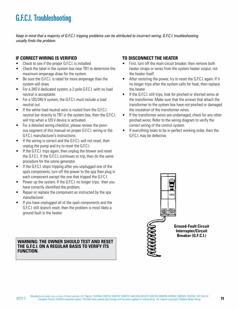
IF CORRECT WIRING IS VERIFIEDCheck to see if the proper G.F.C.I. is installed.Check the label in the system box near TB1 to determine the maximum amperage draw for the system.Be sure the G.F.C.I. is rated for more amperage than the system will draw.For a 240 V dedicated system, a 2-pole G.F.C.I. with no load neutral is acceptable.For a 120/240 V system, the G.F.C.I. must include a load neutral out.If the white load neutral wire is routed from the G.F.C.I. neutral bar directly to TB1 in the system box, then the G.F.C.I. will trip when a 120 V device is activated.For a detailed wiring checklist, please review the previ-ous segment of this manual on proper G.F.C.I. wiring or the G.F.C.I. manufacturer’s instructions.If the wiring is correct and the G.F.C.I. will not reset, then unplug the pump and try to reset the G.F.C.I.If the G.F.C.I. trips again, then unplug the blower and reset the G.F.C.I.. If the G.F.C.I. continues to trip, then do the same procedure for the ozone generator.If the G.F.C.I. stops tripping after you unplugged one of the spa’s components, turn off the power to the spa then plug in each component except the one that tripped the G.F.C.I.Power up the system. If the G.F.C.I. no longer trips, then you have correctly identified the problem. Repair or replace the component as instructed by the spa manufacturer.If you have unplugged all of the spa’s components and the G.F.C.I. still doesn’t reset, then the problem is most likely a ground fault in the heater.
TO DISCONNECT THE HEATERFirst, turn off the main circuit breaker, then remove both heater straps or wires from the system heater output, not the heater itself.After restoring the power, try to reset the G.F.C.I. again. If it no longer trips after the system calls for heat, then replace the heater.If the G.F.C.I. still trips, look for pinched or shorted wires at the transformer. Make sure that the screws that attach the transformer to the system box have not pinched or damaged the insulation of the transformer wires.If the transformer wires are undamaged, check for any other pinched wires. Refer to the wiring diagram to verify the correct wiring of the control system.If everything looks to be in perfect working order, then the G.F.C.I. may be defective.
Keep in mind that a majority of G.F.C.I. tripping problems can be attributed to incorrect wiring. G.F.C.I. troubleshooting usually finds the problem.
Ground-Fault Circuit Interrupter/Circuit Breaker (G.F.C.I.)
WARNING: THE OWNER SHOULD TEST AND RESET THE G.F.C.I. ON A REGULAR BASIS TO VERIFY ITS FUNCTION.
12 Manufactured under one or more of these patents. U.S. Patents: 5332944, 5361215, 5550753, 5559720, 5,883,459, 6253227, 6282370, 6590188, 6976052, 6965815, 7030343, 7,417, 834 b2, Canadian Patent: 2342614, Australian patent: 2373248 other patents both foreign and domestic applied for and pending. All material copyright of Balboa Water Group. 6/22/13
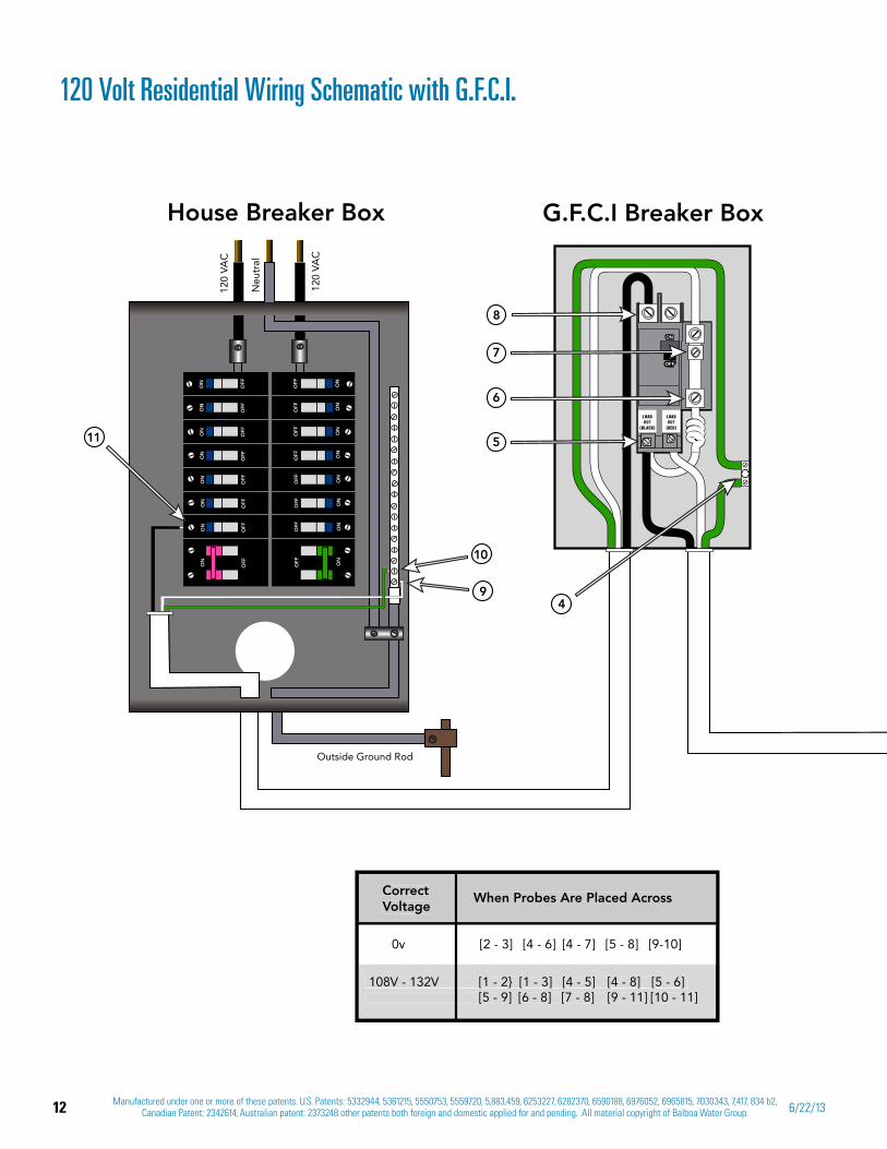
120 Volt Residential Wiring Schematic with G.F.C.I.
120
VAC
120
VAC
Neu
tral
Outside Ground Rod
ON
ON
ON
ON
ON
ON
ON
ON
OFF
OFF
OFF
OFF
OFF
OFF
OFF
OFF
OFF
OFF
OFF
OFF
OFF
OFF
OFF
OFF
ON
ON
ON
ON
ON
ON
ON
ON
House Breaker Box G.F.C.I Breaker Box
4
5
6
8
9
10
11
7
CorrectVoltage
When Probes Are Placed Across
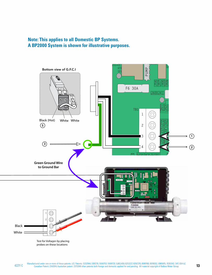
108V - 132V [1 - 2} [1 - 3] [4 - 5] [4 - 8] [5 - 6] [5 - 9] [6 - 8] [7 - 8] [9 - 11] [10 - 11]
0v [2 - 3] [4 - 6] [4 - 7] [5 - 8] [9-10]
108V - 132V [1 - 2} [1 - 3] [4 - 5] [4 - 8] [5 - 6] [5 - 9] [6 - 8] [7 - 8] [9 - 11] [10 - 11]
CorrectVoltage
When Probes Are Placed Across
13Manufactured under one or more of these patents. U.S. Patents: 5332944, 5361215, 5550753, 5559720, 5,883,459, 6253227, 6282370, 6590188, 6976052, 6965815, 7030343, 7,417, 834 b2,
Canadian Patent: 2342614, Australian patent: 2373248 other patents both foreign and domestic applied for and pending. All material copyright of Balboa Water Group.42211 C
5
32
1
J21 J14
J31=CE HTR SEL
TB1
K2
50 9 4
J72
J42
J37
J4
7 5 8
J36
J60
J 6J
J
J53
J41
J12
F6 30A
J56
J57
J55
J59
J51
J52
PUMP 1
1
2
3
4
J14J21
K4
F4 3A SLO-BLOW
J25 J31
J26 J30
115V 115V
230V
F3 0.3A SLO-BLOW
J25=HTR1J26=HTR2J27=HTR3J30=TESTJ31=CE HTR SEL
F7 10A 250VAC
F2 10A 250VAC
J44
3
TB1
J15
ON
10
S1
K5
K1
K3
T1
K2 K8
LIGHT
GND
J33 J32J9
2
K6
4
3
2
1
J45
J110
J79
J54
J72
J42
J3
J37
J4J1
J61
J47
J77
J75
J78
J36
J60
J46J38
J39
J111
J53 J58
J11
J41
J48
J6 J7
J49
J19
J50
J13
J12
J88
J62
F6 30AF8 30A
J56
J57
J55
J59
J51
J52
J98
J10
J81
J20
J18
J43
CIRC PUMP
OZONE
A/V HOT
PUMP 1
J5AUX
J8AUX
J40
REMOTE
J35MAIN
J34MAIN
J109
J27
J91
J22J23
SERIAL
J29VAC
J28AUXFRZ
J17 J16
J101
J108J24
J107
K12
K7
AUX**
1
2
3
4
K9
Green Ground Wire to Ground Bar
Electric Installation 120VAC_with 56405_sunrise_board_030613.ai
Black (Hot) White White
Bottom view of G.F.C.I
1
2
3
4
Test for Voltages by placing
probes on these locations
J32 J33
K4
Black
White
Note: This applies to all Domestic BP Systems.A BP2000 System is shown for illustrative purposes.

14 Manufactured under one or more of these patents. U.S. Patents: 5332944, 5361215, 5550753, 5559720, 5,883,459, 6253227, 6282370, 6590188, 6976052, 6965815, 7030343, 7,417, 834 b2, Canadian Patent: 2342614, Australian patent: 2373248 other patents both foreign and domestic applied for and pending. All material copyright of Balboa Water Group. 6/22/13
240 Volt Residential Wiring Schematic with G.F.C.I.
CorrectVoltage
When Probes Are Placed Across
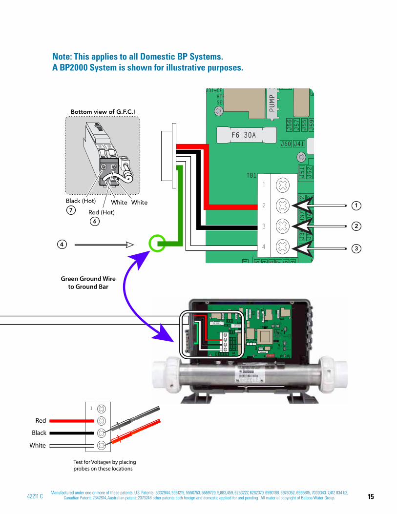
108V - 132V [1 - 3] [5 - 6] [5 - 10] [12 - 14] [13 - 14] [2 - 3] [5 - 7] [5 - 11] [12 - 15] [13 - 15]
0v [3 - 4] [5 - 8] [5 - 9] [12 - 13]
108V - 132V [1 - 3] [5 - 6] [5 - 10] [12 - 14] [13 - 14] [2 - 3] [5 - 7] [5 - 11] [12 - 15] [13 - 15]
CorrectVoltage
When Probes Are Placed Across
216V - 264V [1 - 2] [6 - 7] [10 - 11] [14 - 15]
[5 - 6] [5 - 7]
[12 - 14] [12 - 15]
120
VAC
120
VAC
Neu
tral
Outside Ground Rod
ON
ON
ON
ON
ON
ON
ON
ON
OFF
OFF
OFF
OFF
OFF
OFF
OFF
OFF
OFF
OFF
OFF
OFF
OFF
OFF
OFF
OFF
ON
ON
ON
ON
ON
ON
ON
ON
House Breaker Box G.F.C.I Breaker Box
5
6
7
8
10
11
12
13
15
14
9
15Manufactured under one or more of these patents. U.S. Patents: 5332944, 5361215, 5550753, 5559720, 5,883,459, 6253227, 6282370, 6590188, 6976052, 6965815, 7030343, 7,417, 834 b2,
Canadian Patent: 2342614, Australian patent: 2373248 other patents both foreign and domestic applied for and pending. All material copyright of Balboa Water Group.42211 C
Electric Installation 240VAC_with 56405_sunrise_board_030613.ai
1
2
3
4
43
2
17
6
Test for Voltages by placing
probes on these locations
J32 J33
K4
J21 J14J14J21
K4
F4 3A SLO-BLOW
J25 J31
J26 J30
115V 115V
230V
F3 0.3A SLO-BLOW
J25=HTR1J26=HTR2J27=HTR3J30=TESTJ31=CE HTR SEL
F7 10A 250VAC
F2 10A 250VAC
J44
3
TB1
J15
ON
10
S1
K5
K1
K3
T1
K2 K8
LIGHT
GND
J33 J32J9
2
K6
4
3
2
1
J45
J110
J79
J54
J72
J42
J3
J37
J4J1
J61
J47
J77
J75
J78
J36
J60
J46J38
J39
J111
J53 J58
J11
J41
J48
J6 J7
J49
J19
J50
J13
J12
J88
J62
F6 30AF8 30A
J56
J57
J55
J59
J51
J52
J98
J10
J81
J20
J18
J43
CIRC PUMP
OZONE
A/V HOT
PUMP 1
J5AUX
J8AUX
J40
REMOTE
J35MAIN
J34MAIN
J109
J27
J91
J22J23
SERIAL
J29VAC
J28AUXFRZ
J17 J16
J101
J108J24
J107
K12
K7
AUX**
1
2
3
4
K9
Red
Green Ground Wire to Ground Bar
Black
White
Red (Hot)
Black (Hot) White White
Bottom view of G.F.C.I
J31=CE HTR SEL
TB1
K2
50 9 4
J72
J42
J37
J4
7 5 8
J36
J60
J 6J
J
J53
J41
J12
F6 30A
J56
J57
J55
J59
J51
J52
PUMP 1
1
2
3
4
Note: This applies to all Domestic BP Systems.A BP2000 System is shown for illustrative purposes.
16 Manufactured under one or more of these patents. U.S. Patents: 5332944, 5361215, 5550753, 5559720, 5,883,459, 6253227, 6282370, 6590188, 6976052, 6965815, 7030343, 7,417, 834 b2, Canadian Patent: 2342614, Australian patent: 2373248 other patents both foreign and domestic applied for and pending. All material copyright of Balboa Water Group. 6/22/13
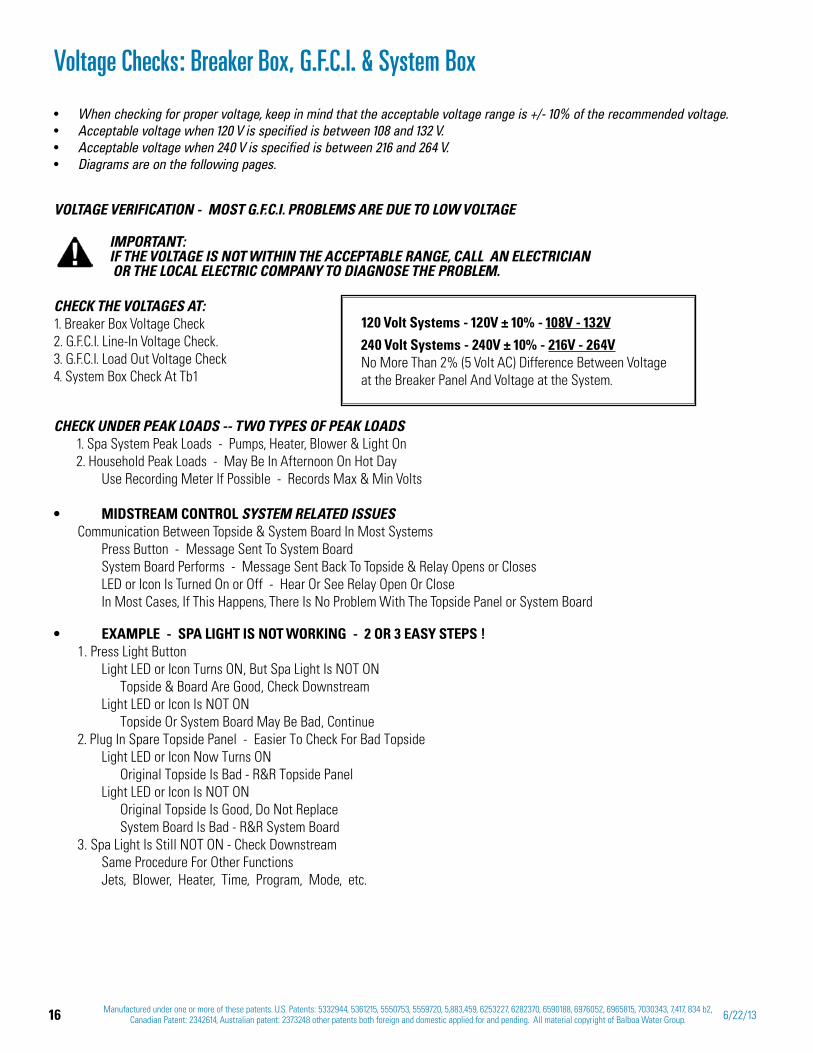
VOLTAGE VERIFICATION - MOST G.F.C.I. PROBLEMS ARE DUE TO LOW VOLTAGE
IMPORTANT: IF THE VOLTAGE IS NOT WITHIN THE ACCEPTABLE RANGE, CALL AN ELECTRICIAN OR THE LOCAL ELECTRIC COMPANY TO DIAGNOSE THE PROBLEM.
CHECK THE VOLTAGES AT: 1. Breaker Box Voltage Check 2. G.F.C.I. Line-In Voltage Check. 3. G.F.C.I. Load Out Voltage Check 4. System Box Check At Tb1
CHECK UNDER PEAK LOADS -- TWO TYPES OF PEAK LOADS1. Spa System Peak Loads - Pumps, Heater, Blower & Light On2. Household Peak Loads - May Be In Afternoon On Hot Day Use Recording Meter If Possible - Records Max & Min Volts
SYSTEM RELATED ISSUESCommunication Between Topside & System Board In Most Systems Press Button - Message Sent To System Board System Board Performs - Message Sent Back To Topside & Relay Opens or Closes LED or Icon Is Turned On or Off - Hear Or See Relay Open Or Close In Most Cases, If This Happens, There Is No Problem With The Topside Panel or System Board
1. Press Light Button Light LED or Icon Turns ON, But Spa Light Is NOT ON Topside & Board Are Good, Check Downstream Light LED or Icon Is NOT ON Topside Or System Board May Be Bad, Continue2. Plug In Spare Topside Panel - Easier To Check For Bad Topside Light LED or Icon Now Turns ON Original Topside Is Bad - R&R Topside Panel Light LED or Icon Is NOT ON Original Topside Is Good, Do Not Replace System Board Is Bad - R&R System Board3. Spa Light Is Still NOT ON - Check Downstream Same Procedure For Other Functions Jets, Blower, Heater, Time, Program, Mode, etc.
Voltage Checks: Breaker Box, G.F.C.I. & System Box
When checking for proper voltage, keep in mind that the acceptable voltage range is +/- 10% of the recommended voltage. Acceptable voltage when 120 V is specified is between 108 and 132 V. Acceptable voltage when 240 V is specified is between 216 and 264 V.Diagrams are on the following pages.
120 Volt Systems - 120V ± 10% - 108V - 132V
240 Volt Systems - 240V ± 10% - 216V - 264VNo More Than 2% (5 Volt AC) Difference Between Voltage at the Breaker Panel And Voltage at the System.
17Manufactured under one or more of these patents. U.S. Patents: 5332944, 5361215, 5550753, 5559720, 5,883,459, 6253227, 6282370, 6590188, 6976052, 6965815, 7030343, 7,417, 834 b2,
Canadian Patent: 2342614, Australian patent: 2373248 other patents both foreign and domestic applied for and pending. All material copyright of Balboa Water Group.42211 C
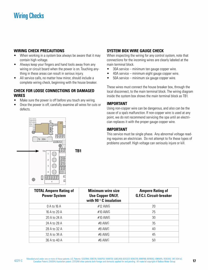
Wiring Checks
WIRING CHECK PRECAUTIONSWhen working in a system box always be aware that it may contain high voltage.Always keep your fingers and hand tools away from any wiring or circuit board when the power is on. Touching any-thing in these areas can result in serious injury.All service calls, no matter how minor, should include a complete wiring check, beginning with the house breaker.
CHECK FOR LOOSE CONNECTIONS OR DAMAGED WIRES
Make sure the power is off before you touch any wiring.Once the power is off, carefully examine all wires for cuts or defects.
SYSTEM BOX WIRE GAUGE CHECKWhen inspecting the wiring for any control system, note that connections for the incoming wires are clearly labeled at the main terminal block.
30A service – minimum ten gauge copper wire.40A service – minimum eight gauge copper wire.50A service – minimum six gauge copper wire.
These wires must connect the house breaker box, through the local disconnect, to the main terminal block. The wiring diagram inside the system box shows the main terminal block as TB1.
IMPORTANTUsing non-copper wire can be dangerous, and also can be the cause of a spa’s malfunction. If non-copper wire is used at any point, we do not recommend servicing the spa until an electri-cian replaces it with the proper gauge copper wire.
IMPORTANTThis service must be single phase. Any abnormal voltage read-ing requires an electrician. Do not attempt to fix these types of problems yourself. High voltage can seriously injure or kill.
TOTALTT Ampere Rating ofPower System
Minimum wire size Use Copper ONLY,LL
with 90 o C insulation
Ampere Rating ofG.F.C.I. Circuit-breaker
0 A to 16 A #12 AWG 20
16 A to 20 A #10 AWG 25
20 A to 24 A #10 AWG 30
24 A to 28 A #8 AWG 35
28 A to 32 A #8 AWG 40
32 A to 36 A #6 AWG 45
36 A to 40 A #6 AWG 50
TB1
18 Manufactured under one or more of these patents. U.S. Patents: 5332944, 5361215, 5550753, 5559720, 5,883,459, 6253227, 6282370, 6590188, 6976052, 6965815, 7030343, 7,417, 834 b2, Canadian Patent: 2342614, Australian patent: 2373248 other patents both foreign and domestic applied for and pending. All material copyright of Balboa Water Group. 6/22/13
Testing a System with Power
LOW VOLTAGEAt Balboa, it’s been our experience that the majority of the problems associated with electronic control systems are due to low voltage.
BROWN OUTS“Brown outs” can have an effect on the spa’s operation in a variety of ways. The control panel may go blank, have scrambled messages on the LCD, or only a few features will function.
CHECKING THE SYSTEM POWER INPUT FUSE
WARNING
THESE PROCEDURES ARE PERFORMED WHILE THE SYSTEM IS POWERED UP AND
RUNNING UNDER PEAK LOADS.
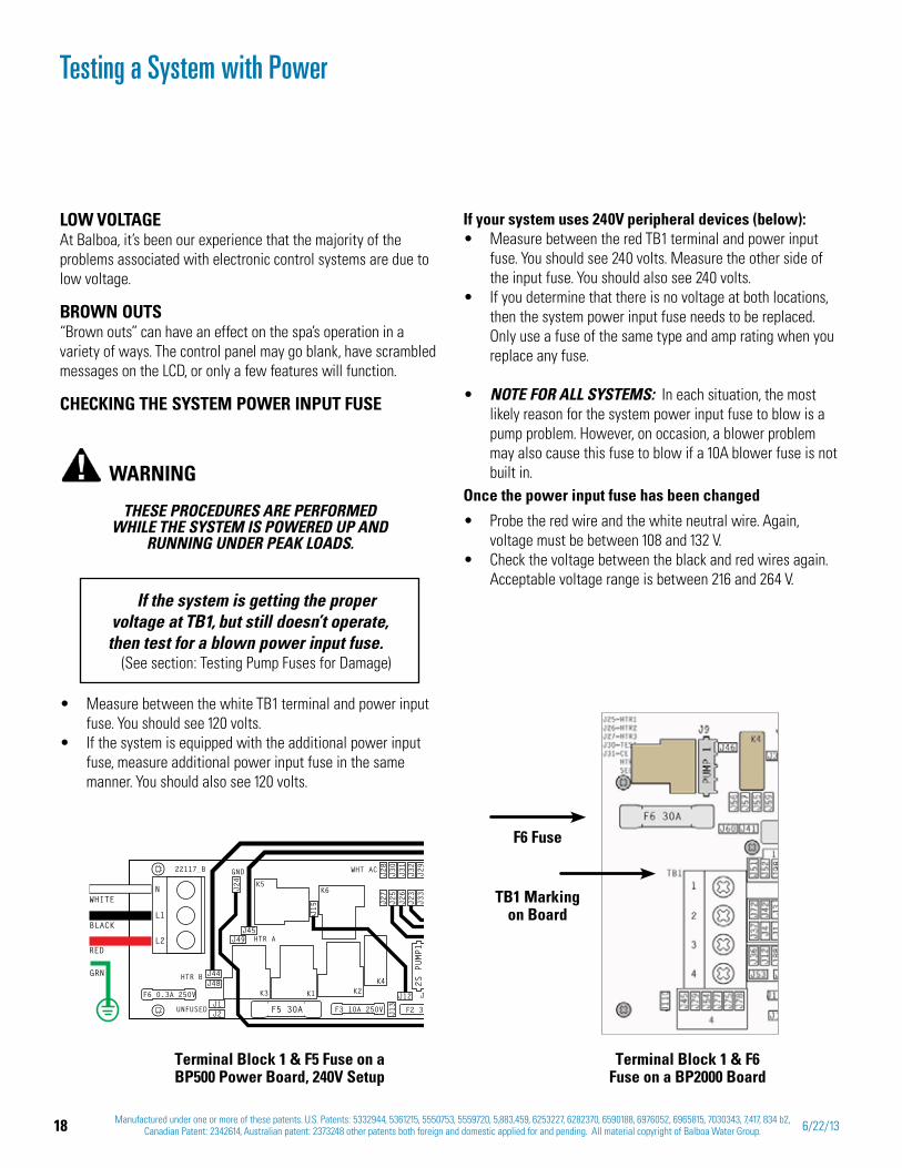
Measure between the white TB1 terminal and power input fuse. You should see 120 volts. If the system is equipped with the additional power input fuse, measure additional power input fuse in the same manner. You should also see 120 volts.
If the system is getting the proper voltage at TB1, but still doesn’t operate, then test for a blown power input fuse.
(See section: Testing Pump Fuses for Damage)
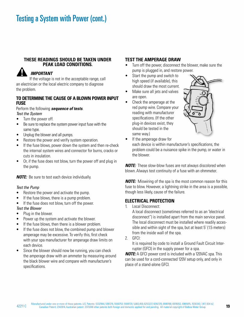
F6 Fuse
Terminal Block 1 & F6 Fuse on a BP2000 Board
Terminal Block 1 & F5 Fuse on a BP500 Power Board, 240V Setup
TB1 Marking on Board
If your system uses 240V peripheral devices (below):Measure between the red TB1 terminal and power input fuse. You should see 240 volts. Measure the other side of the input fuse. You should also see 240 volts.If you determine that there is no voltage at both locations, then the system power input fuse needs to be replaced. Only use a fuse of the same type and amp rating when you replace any fuse.
NOTE FOR ALL SYSTEMS: In each situation, the most likely reason for the system power input fuse to blow is a pump problem. However, on occasion, a blower problem may also cause this fuse to blow if a 10A blower fuse is not built in.
Once the power input fuse has been changed
Probe the red wire and the white neutral wire. Again, voltage must be between 108 and 132 V.Check the voltage between the black and red wires again. Acceptable voltage range is between 216 and 264 V.
L2
L1
N
F3 10A 250V F2 3A
F6 0.3A 250V
J44J48
J1J2
J24
J45J49
J15
J13
J27
J25
J26
J23
J33
J28
J30
J31
J32
J29
J12 J
F5 30A
GND
K3
K5K6
K2K1
K4
22117_B WHT AC
HTR A
HTR B
UNFUSED
2S PUMP1
WHITE
BLACK
RED
GRN
19Manufactured under one or more of these patents. U.S. Patents: 5332944, 5361215, 5550753, 5559720, 5,883,459, 6253227, 6282370, 6590188, 6976052, 6965815, 7030343, 7,417, 834 b2,
Canadian Patent: 2342614, Australian patent: 2373248 other patents both foreign and domestic applied for and pending. All material copyright of Balboa Water Group.42211 C
Testing a System with Power (cont.)
THESE READINGS SHOULD BE TAKEN UNDER PEAK LOAD CONDITIONS.
IMPORTANTIf the voltage is not in the acceptable range, call
an electrician or the local electric company to diagnose the problem.
TO DETERMINE THE CAUSE OF A BLOWN POWER INPUT FUSEPerform the following sequence of tests.Test the System
Turn the power off.Be sure to replace the system power input fuse with the same type.Unplug the blower and all pumps.Restore the power and verify system operation.If the fuse blows, power down the system and then re-check the internal system wires and connector for burns, cracks or cuts in insulation.Or, if the fuse does not blow, turn the power off and plug in the pump.
NOTE: Be sure to test each device individually.
Test the PumpRestore the power and activate the pump.If the fuse blows, there is a pump problem.If the fuse does not blow, turn off the power.
Test the BlowerPlug in the blower.Power up the system and activate the blower.If the fuse blows, then there is a blower problem.If the fuse does not blow, the combined pump and blower amperage may be excessive. To verify this, first check with your spa manufacturer for amperage draw limits on each device.Since the blower should now be running, you can check the amperage draw with an ammeter by measuring around the black blower wire and compare with manufacturer’s specifications.
TEST THE AMPERAGE DRAWTurn off the power, disconnect the blower, make sure the pump is plugged in, and restore power.Start the pump and switch to high speed (if available), this should draw the most current.Make sure all jets and valves are open.Check the amperage at the red pump wire. Compare your reading with manufacturer specifications. (If the other plug-in devices exist, they should be tested in the same way.)If the amperage draw for each device is within manufacturer’s specifications, the problem could be a nuisance spike in the pump, or water in the blower.
NOTE: These slow-blow fuses are not always discolored when blown. Always test continuity of a fuse with an ohmmeter.
NOTE: Miswiring of the spa is the most common reason for this fuse to blow. However, a lightning strike in the area is a possible, though less likely, cause of the failure.
ELECTRICAL PROTECTION1. Local Disconnect:
A local disconnect (sometimes referred to as an “electrical disconnect”) is installed apart from the main service panel. The local disconnect must be installed where readily acces-sible and within sight of the spa, but at least 5’ (1.5 meters) from the inside wall of the spa.
2. GFCI: It is required by code to install a Ground Fault Circuit Inter-rupter (GFCI) in the supply power for a spa.
NOTE: A GFCI power cord is included with a 120VAC spa. This can be used for a cord-connected 120V setup only, and only in place of a stand-alone GFCI.
20 Manufactured under one or more of these patents. U.S. Patents: 5332944, 5361215, 5550753, 5559720, 5,883,459, 6253227, 6282370, 6590188, 6976052, 6965815, 7030343, 7,417, 834 b2, Canadian Patent: 2342614, Australian patent: 2373248 other patents both foreign and domestic applied for and pending. All material copyright of Balboa Water Group. 6/22/13
SAFETY AND ELECTRICAL SYSTEMS Use minimum 6AWG copper conductors only.Torque field connections between 21 and 23 in-lbs.Connect only to a circuit protected by a Class A Ground Fault Circuit Interrupter (GFCI) CSA enclosure: Type 2.The BP Spa Control Systems are classified as a “continuous duty appliance” and is intended primarily for installation at a single family dwelling. The installation recommendations and instructions contained in this manual are directed solely toward these issues.
WARNING!If there is any doubt whether the system that you are installing into does not have these features, contact a licensed, qualified electrician. Do not attempt to modify the wiring yourself.
PRELIMINARY PANEL CHECKIf the problem is not obvious, look on the topside control panel for diagnostic messages. If no messages are seen, run through all spa functions and note any inconsistent operation.Most error messages are stored in the fault log. To view the fault log, the spa must be in test mode and the spa light must be turned on.
Once you have determined that proper voltage is running through the circuit board and transformer, continue to the topside control panel. A panel that is not functioning properly may include the following symptoms: low voltage such as missing or scrambled segments, missing icons on the LCD, non-functional LED’s, or nonfunctional buttons. If any of these symptoms are present, perform the following:
Turn the power off and unplug the panel from the circuit board.Then, plug in your test panel and restore power. If every-thing functions normally, replace the topside panel.Disconnect ozone generator (if applicable).If you still see symptoms of low voltage, such as a sluggish, blank or partially blank panel, or if the display or the LED’s do not function at all, turn the power off; unplug the ozone generator (if equipped); then restore power to the system. If the problem persists, turn off the power and replace the circuit board.
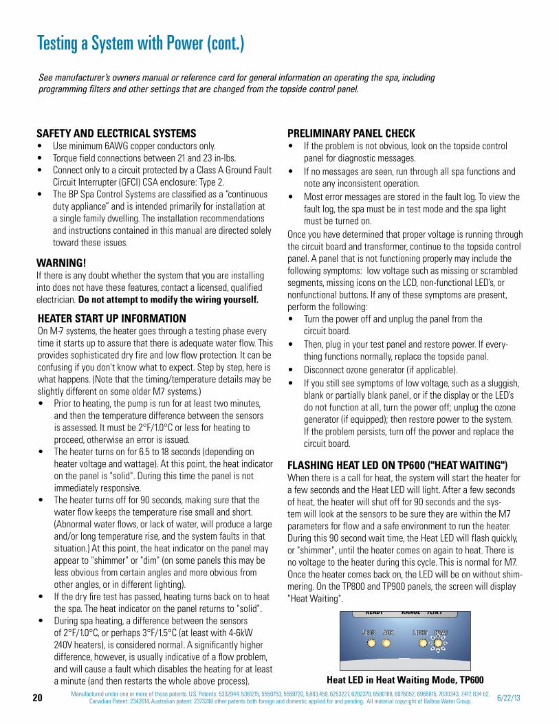
FLASHING HEAT LED ON TP600 ("HEAT WAITING")When there is a call for heat, the system will start the heater for a few seconds and the Heat LED will light. After a few seconds of heat, the heater will shut off for 90 seconds and the sys-tem will look at the sensors to be sure they are within the M7 parameters for flow and a safe environment to run the heater. During this 90 second wait time, the Heat LED will flash quickly, or "shimmer", until the heater comes on again to heat. There is no voltage to the heater during this cycle. This is normal for M7. Once the heater comes back on, the LED will be on without shim-mering. On the TP800 and TP900 panels, the screen will display "Heat Waiting".
HEATER START UP INFORMATIONOn M-7 systems, the heater goes through a testing phase every time it starts up to assure that there is adequate water flow. This provides sophisticated dry fire and low flow protection. It can be confusing if you don't know what to expect. Step by step, here is what happens. (Note that the timing/temperature details may be slightly different on some older M7 systems.)
Prior to heating, the pump is run for at least two minutes, and then the temperature difference between the sensors is assessed. It must be 2°F/1.0°C or less for heating to proceed, otherwise an error is issued.The heater turns on for 6.5 to 18 seconds (depending on heater voltage and wattage). At this point, the heat indicator on the panel is "solid". During this time the panel is not immediately responsive.The heater turns off for 90 seconds, making sure that the water flow keeps the temperature rise small and short. (Abnormal water flows, or lack of water, will produce a large and/or long temperature rise, and the system faults in that situation.) At this point, the heat indicator on the panel may appear to "shimmer" or "dim" (on some panels this may be less obvious from certain angles and more obvious from other angles, or in different lighting).If the dry fire test has passed, heating turns back on to heat the spa. The heat indicator on the panel returns to "solid".During spa heating, a difference between the sensors of 2°F/1.0°C, or perhaps 3°F/1.5°C (at least with 4-6kW 240V heaters), is considered normal. A significantly higher difference, however, is usually indicative of a flow problem, and will cause a fault which disables the heating for at least a minute (and then restarts the whole above process).
See manufacturer’s owners manual or reference card for general information on operating the spa, including programming filters and other settings that are changed from the topside control panel.
Testing a System with Power (cont.)
Heat LED in Heat Waiting Mode, TP600
JETTSSSS AUX LIGHT HHHEATJETS AUX LIGHT HEAT
21Manufactured under one or more of these patents. U.S. Patents: 5332944, 5361215, 5550753, 5559720, 5,883,459, 6253227, 6282370, 6590188, 6976052, 6965815, 7030343, 7,417, 834 b2,
Canadian Patent: 2342614, Australian patent: 2373248 other patents both foreign and domestic applied for and pending. All material copyright of Balboa Water Group.42211 C
Testing a System with Power (cont.)
MOST PROBABLE OVERHEATING CAUSES, INSPECT THESE FIRST
Check slice or ball valves. Make sure that they are open.Make sure the correct pump is installed.Clean the filter/skimmer if there is any blockage.Check heater element alignment.Check for debris on the heater element.In extremely hot weather, check for proper cabinet ventila-tion.Make sure the temperature sensor is fully inserted into the sensor fitting on the heater.Check for excessive filter duration.Check the water level.Check the water temperature with an accurate temperature thermometer. Remove the spa cover and allow the water to cool to below 108° F. Adding cool water may be necessary. Touch any button to reset the system. If the water is still hotter than the set temperature, press the blower button (if applicable) to cool the spa.If the Problem Recurs, test the Sensor Set.
NOTE: A common programming mistake is overlapping filter times that may cause the spa to filter continuously.
If alternating with temperature, it may just be a temporary condition. If flashing by itself, spa is shut down.If the panel also displays “Service Req” spa is shut down.If the spa shuts down due to this error, one (or both) of the sensors are probably reading several degrees off. If the problem recurs, test the sensor set.
FREEZE CONDITIONWhen either sensor reads below 40°F (4°C), the system provides freeze protection. It automatically activates the pump (and the heater if necessary) to circulate the water and warm the plumb-ing. The equipment stays on until the sensors detect that the spa temperature has risen to within 15°F of the set temperature. The other pumps and the blower will purge for 30 seconds to 2 minutes at the end of the freeze condition. If pump 1 was turned on due to this reason alone, this message will appear for up to two minutes right after very cold water is detected.
NOTE: Internal freeze protection only functions when there is proper power running to the spa, and the control system is operational. Using an optional freeze sensor may be necessary in extreme climates to prevent plumbing damage, but will only
work properly if placed inside the spa skirt in the coldest area.All spa models are different in shape and size and have different thermal characteristics; therefore, Balboa Water Group cannot be held responsible for freeze damage to the spa’s plumbing. Testing is the responsibility of the spa manufacturer and must be done to determine the best location for the freeze sensor.
SOME TROUBLESHOOTING SCENARIOSYou find out the system is in “OHH”. This alone doesn't explain a lot. What led up to the “OHH” is much more important. If it's a Prestige, review the fault log carefully. Otherwise, see if the user has any additional information (for example, how long before the “OHH” was the spa panel last checked, and how hot was the water then). If the spa has cooled, see whether the problem can happen again, this time watching carefully to see if there are additional clues leading to the “OHH” (for example, other messages that appear shortly before the “OHH” happens).
You find out the system keeps showing “HFL,” or is now in “LF,” or is shut down due to a "dry" fault. Put the spa in test mode with the light on, so that you see the two sensor temperatures. Are they normal (within 1°F/0.5°C) when not heating? How far apart are they when heating? “HFL” happens when they are 6°F/3°C apart (4°F/2°C on 120V and other low-heater-wattage systems), see how quickly that happens after heating starts. If it's getting close to that right away, it's probably a consistent flow problem, but if it's nowhere close to the “HFL”-causing temperature difference, the flow problem may be intermittent or only occur in certain specific situations.
TEST MODETest modes vary for different systems and configurations. Please refer to the specific Tech Sheet applicable.
MESSAGE CODESRefer to Tech Sheets for each system code. Or, a general set of codes for BP systems is found under the sectionTP400, TP600 Message Codes in this manual. Message codes are the same for all TP panels.
22 Manufactured under one or more of these patents. U.S. Patents: 5332944, 5361215, 5550753, 5559720, 5,883,459, 6253227, 6282370, 6590188, 6976052, 6965815, 7030343, 7,417, 834 b2, Canadian Patent: 2342614, Australian patent: 2373248 other patents both foreign and domestic applied for and pending. All material copyright of Balboa Water Group. 6/22/13
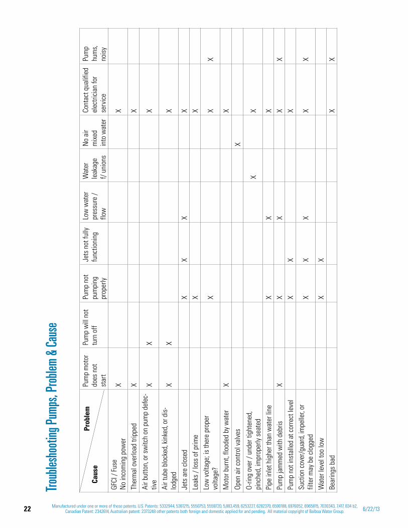
Troub
lesho
oting
Pum
ps, P
roblem
& Ca
use
Pum
p m
otor
do
es n
ot
star
t
Pum
p w
ill n
ot
turn
off
Pum
p no
t pu
mpi
ng
prop
erly
Jets
not
fully
fu
nctio
ning
Low
wat
er
pres
sure
/ flo
w
Wat
er
leak
age
f/
uni
ons
No
air
mix
edin
to w
ater
Cont
act q
ualif
ied
elec
tricia
n fo
r se
rvic
e
Pum
phu
ms,
nois
yGF
CI /
Fuse
No
inco
min
g po
wer
XX
Ther
mal
ove
rload
trip
ped
XX
Air b
utto
n, or
sw
itch
on p
ump
defe
c-tiv
eX
XX
Air t
ube
bloc
ked,
kinke
d, or
dis
-lo
dged
XX
X
Jets
are
clos
edX
XX
XLe
aks
/ los
s of
prim
eX
XLo
w v
olta
ge; i
s th
ere
prop
er
volta
ge?
XX
X
Mot
or b
urnt
, flo
oded
by
wat
erX
X
Open
air
cont
rol v
alve
sX
O-rin
g ov
er /
unde
r tig
hten
ed,
pinc
hed,
impr
oper
ly s
eate
dX
X
Pipe
inle
t hig
her t
han
wat
er li
neX
XX
Pum
p ja
mm
ed w
ith d
ebris
X
XX
XX
Pum
p no
t ins
talle
d at
cor
rect
leve
lX
XX
Suct
ion
cove
r/gu
ard,
impe
ller,
or
filte
r may
be
clogg
edX
XX
XX
Wat
er le
vel t
oo lo
wX
XBe
arin
gs b
adX
X
Prob
lem
Caus
e
23Manufactured under one or more of these patents. U.S. Patents: 5332944, 5361215, 5550753, 5559720, 5,883,459, 6253227, 6282370, 6590188, 6976052, 6965815, 7030343, 7,417, 834 b2,
Canadian Patent: 2342614, Australian patent: 2373248 other patents both foreign and domestic applied for and pending. All material copyright of Balboa Water Group.42211 C
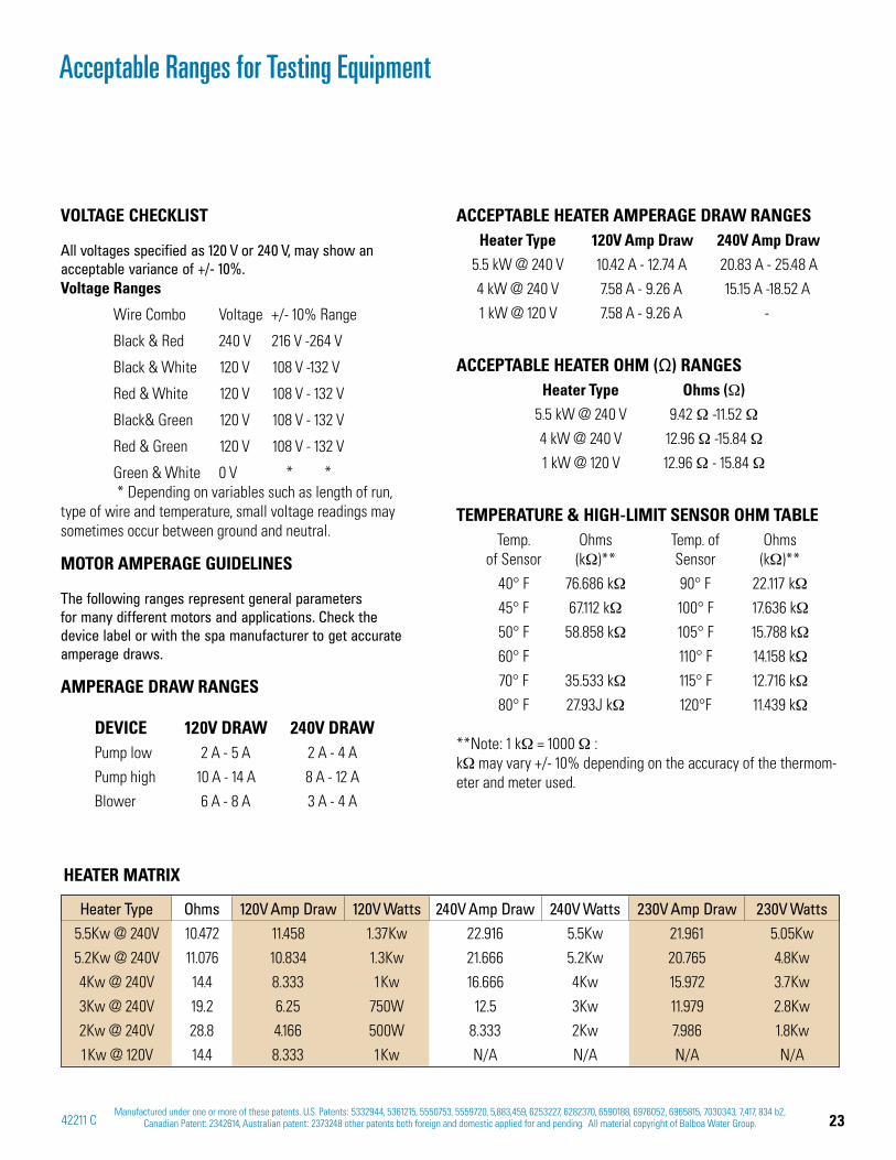
VOLTAGE CHECKLIST
All voltages specified as 120 V or 240 V, may show an acceptable variance of +/- 10%. Voltage Ranges
Wire Combo Voltage +/- 10% Range
Black & Red 240 V 216 V -264 V
Black & White 120 V 108 V -132 V
Red & White 120 V 108 V - 132 V
Black& Green 120 V 108 V - 132 V
Red & Green 120 V 108 V - 132 V
Green & White 0 V * * * Depending on variables such as length of run, type of wire and temperature, small voltage readings may sometimes occur between ground and neutral.
MOTOR AMPERAGE GUIDELINES
The following ranges represent general parameters for many different motors and applications. Check the device label or with the spa manufacturer to get accurate amperage draws.
AMPERAGE DRAW RANGES
DEVICE 120V DRAW 240V DRAW Pump low 2 A - 5 A 2 A - 4 A
Pump high 10 A - 14 A 8 A - 12 A
Blower 6 A - 8 A 3 A - 4 A
Acceptable Ranges for Testing Equipment
ACCEPTABLE HEATER AMPERAGE DRAW RANGESHeater Type 120V Amp Draw 240V Amp Draw
5.5 kW @ 240 V 10.42 A - 12.74 A 20.83 A - 25.48 A
4 kW @ 240 V 7.58 A - 9.26 A 15.15 A -18.52 A
1 kW @ 120 V 7.58 A - 9.26 A -
ACCEPTABLE HEATER OHM ( ) RANGES Heater Type Ohms ( )
5.5 kW @ 240 V 9.42 -11.52
4 kW @ 240 V 12.96 -15.84
1 kW @ 120 V 12.96 - 15.84
TEMPERATURE & HIGH-LIMIT SENSOR OHM TABLE Temp.
of Sensor Ohms (k )**
Temp. of Sensor
Ohms (k )**
40° F 76.686 k 90° F 22.117 k
45° F 67.112 k 100° F 17.636 k
50° F 58.858 k 105° F 15.788 k
60° F 110° F 14.158 k
70° F 35.533 k 115° F 12.716 k
80° F 27.93J k 120°F 11.439 k
**Note: 1 k = 1000 : k may vary +/- 10% depending on the accuracy of the thermom-eter and meter used.
Heater Type Ohms 120V Amp Draw 120V Watts 240V Amp Draw 240V Watts 230V Amp Draw 230V Watts5.5Kw @ 240V 10.472 11.458 1.37Kw 22.916 5.5Kw 21.961 5.05Kw
5.2Kw @ 240V 11.076 10.834 1.3Kw 21.666 5.2Kw 20.765 4.8Kw
4Kw @ 240V 14.4 8.333 1Kw 16.666 4Kw 15.972 3.7Kw
3Kw @ 240V 19.2 6.25 750W 12.5 3Kw 11.979 2.8Kw
2Kw @ 240V 28.8 4.166 500W 8.333 2Kw 7.986 1.8Kw
1Kw @ 120V 14.4 8.333 1Kw N/A N/A N/A N/A
HEATER MATRIX
24 Manufactured under one or more of these patents. U.S. Patents: 5332944, 5361215, 5550753, 5559720, 5,883,459, 6253227, 6282370, 6590188, 6976052, 6965815, 7030343, 7,417, 834 b2, Canadian Patent: 2342614, Australian patent: 2373248 other patents both foreign and domestic applied for and pending. All material copyright of Balboa Water Group. 6/22/13
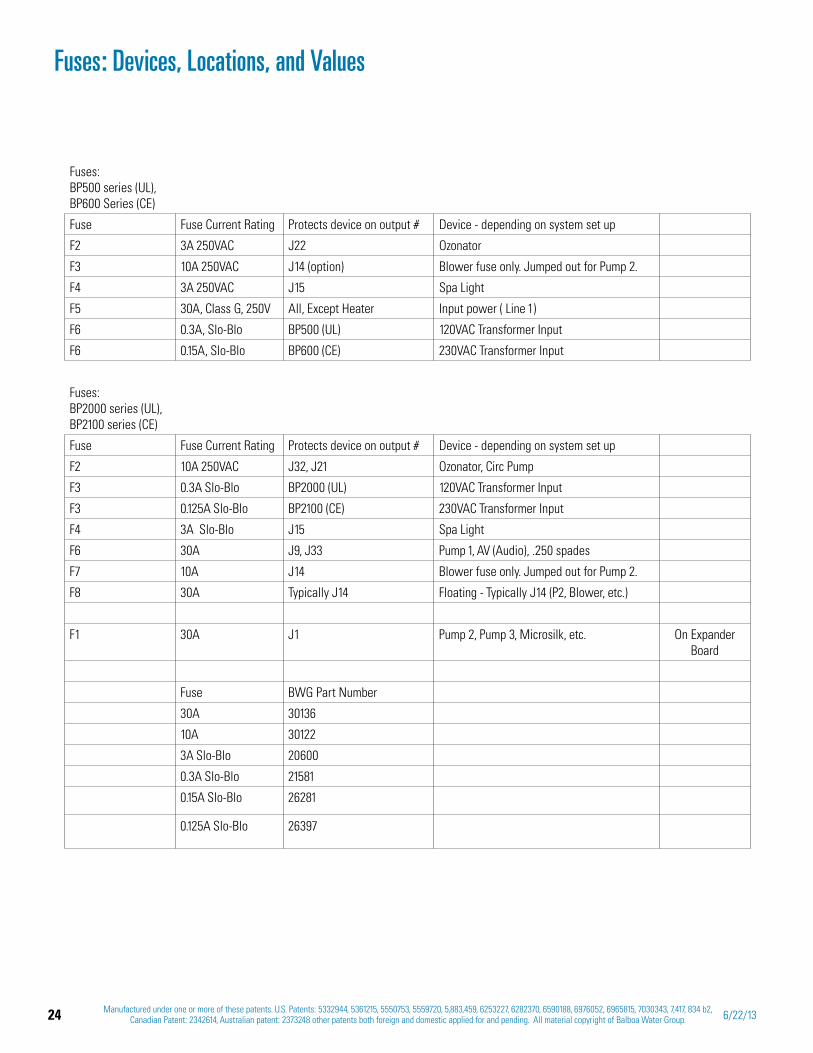
Fuses: BP500 series (UL), BP600 Series (CE)
Fuse Fuse Current Rating Protects device on output # Device - depending on system set up
F2 3A 250VAC J22 Ozonator
F3 10A 250VAC J14 (option) Blower fuse only. Jumped out for Pump 2.
F4 3A 250VAC J15 Spa Light
F5 30A, Class G, 250V All, Except Heater Input power ( Line 1)
F6 0.3A, Slo-Blo BP500 (UL) 120VAC Transformer Input
F6 0.15A, Slo-Blo BP600 (CE) 230VAC Transformer Input
Fuses: BP2000 series (UL), BP2100 series (CE)
Fuse Fuse Current Rating Protects device on output # Device - depending on system set up
F2 10A 250VAC J32, J21 Ozonator, Circ Pump
F3 0.3A Slo-Blo BP2000 (UL) 120VAC Transformer Input
F3 0.125A Slo-Blo BP2100 (CE) 230VAC Transformer Input
F4 3A Slo-Blo J15 Spa Light
F6 30A J9, J33 Pump 1, AV (Audio), .250 spades
F7 10A J14 Blower fuse only. Jumped out for Pump 2.
F8 30A Typically J14 Floating - Typically J14 (P2, Blower, etc.)
F1 30A J1 Pump 2, Pump 3, Microsilk, etc. On Expander Board
Fuse BWG Part Number
30A 30136
10A 30122
3A Slo-Blo 20600
0.3A Slo-Blo 21581
0.15A Slo-Blo 26281
0.125A Slo-Blo 26397
Fuses: Devices, Locations, and Values
25Manufactured under one or more of these patents. U.S. Patents: 5332944, 5361215, 5550753, 5559720, 5,883,459, 6253227, 6282370, 6590188, 6976052, 6965815, 7030343, 7,417, 834 b2,
Canadian Patent: 2342614, Australian patent: 2373248 other patents both foreign and domestic applied for and pending. All material copyright of Balboa Water Group.42211 C
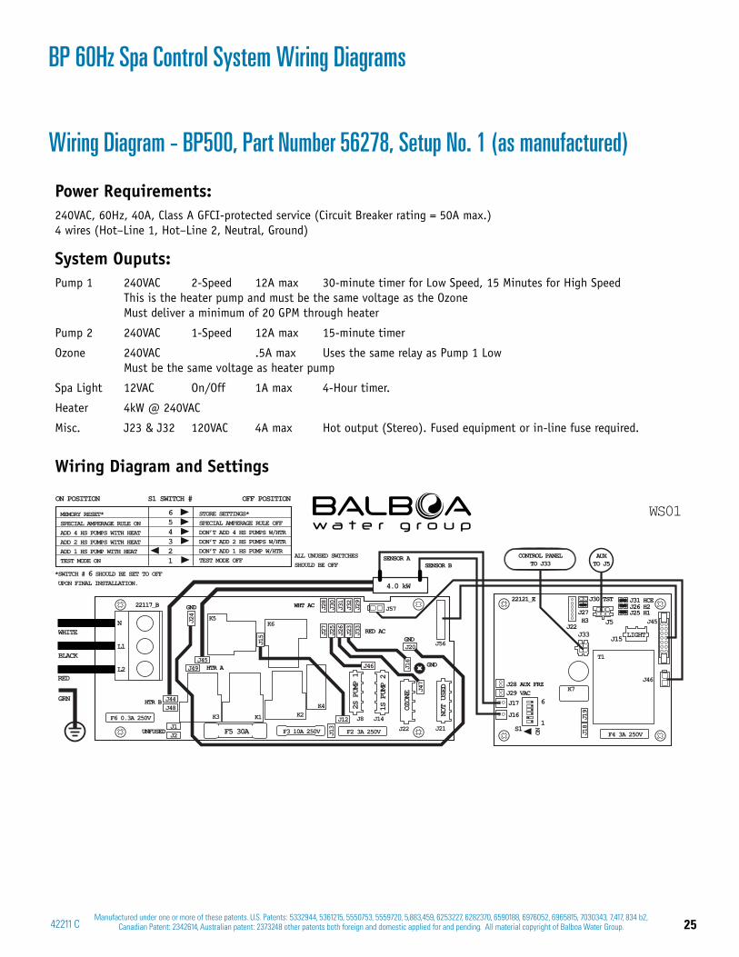
Wiring Diagram - BP500, Part Number 56278, Setup No. 1 (as manufactured)
Power Requirements:240VAC, 60Hz, 40A, Class A GFCI-protected service (Circuit Breaker rating = 50A max.)4 wires (Hot–Line 1, Hot–Line 2, Neutral, Ground)
System Ouputs:Pump 1 240VAC 2-Speed 12A max 30-minute timer for Low Speed, 15 Minutes for High Speed This is the heater pump and must be the same voltage as the Ozone Must deliver a minimum of 20 GPM through heater
Pump 2 240VAC 1-Speed 12A max 15-minute timer
Ozone 240VAC .5A max Uses the same relay as Pump 1 Low Must be the same voltage as heater pump
Spa Light 12VAC On/Off 1A max 4-Hour timer.
Heater 4kW @ 240VAC
Misc. J23 & J32 120VAC 4A max Hot output (Stereo). Fused equipment or in-line fuse required.
Wiring Diagram and Settings
WS01
L2
L1
N
F3 10A 250V F2 3A 250V
F6 0.3A 250V
J44J48
J1J2
J24
J45J49
J15
J16
J47
J13
J27
J25
J26
J23
J33
J28
J30
J31
J32
J29
J12
J46
J20
J57
J8 J14J22 J21
J56
F5 30A
GND
K3
K5K6
K2K1
K4 OZON
E
22117_B
RED AC
GND
GND
WHT AC
HTR A
HTR B
UNFUSED S1
J45
J46
F4 3A 250VJ18
J19
K7
T1
J15J33
J31 HCEJ30 TST
J27H3
J22
J26 H2J25 H1
J17
J16
J29 VACJ28 AUX FRZ
J5
LIGHT
ON
22121_E
1
6
CONTROL PANELTO J33
AUXTO J5
ALL UNUSED SWITCHES SHOULD BE OFF
STORE SETTINGS*SPECIAL AMPERAGE RULE OFFDON’T ADD 4 HS PUMPS W/HTRDON’T ADD 2 HS PUMPS W/HTRDON’T ADD 1 HS PUMP W/HTRTEST MODE OFF
MEMORY RESET*SPECIAL AMPERAGE RULE ONADD 4 HS PUMPS WITH HEATADD 2 HS PUMPS WITH HEATADD 1 HS PUMP WITH HEATTEST MODE ON
654321
ON POSITION S1 SWITCH # OFF POSITION
*SWITCH # 6 SHOULD BE SET TO OFF UPON FINAL INSTALLATION.
SENSOR ASENSOR B
NOT
USED
2S P
UMP
1
1S P
UMP
2
WHITE
BLACK
RED
GRN
4.0 kW
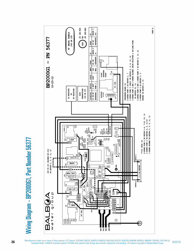
BP 60Hz Spa Control System Wiring Diagrams
26 Manufactured under one or more of these patents. U.S. Patents: 5332944, 5361215, 5550753, 5559720, 5,883,459, 6253227, 6282370, 6590188, 6976052, 6965815, 7030343, 7,417, 834 b2, Canadian Patent: 2342614, Australian patent: 2373248 other patents both foreign and domestic applied for and pending. All material copyright of Balboa Water Group. 6/22/13
F4 3A SLO-BLOW
J25
J31
J26
J30
115V
115V
230V
F3 0.3A SLO-BLOW
J25=HTR1
J26=HTR2
J27=HTR3
J30=TEST
J31=CE
HTR
SEL
F7 10A 250VAC
F2 10A 250VAC
J44
3
TB1
J15
ON
10
S1
K5K1
K3
T1
K2
K4
K8
LIGH
T
GND
J33
J21
J32
J9
1 2 3 4
2
K6
4
32
1
J45
J110
J79J54
J72J42J3
J37J4J1
J61 J47
J77J75J78
J36
J60
J46
J38
J39
J111
J53
J58
J11
J41
J48 J6
J7
J49
J19
J50
J13
J12J88J62
F6 30A
F8 30A
J56J57J55J59
J51J52J98
J10
J81
J20
J18
J43
CIRC PUMP
OZONE
A/V HOT
PUMP 1
J14
K9
J5 AUX
J8 AUX
J40
REMOTE
J35
MAIN
J34
MAIN
J109
J27
J91
J22
J23
SERIAL
J29
VAC
J28
AUX
FRZ
J17
J16
24082_D
J101
J108
J24
J107
K12
K7
TP (
MAIN
) PA
NELS
J34
OR J
35
10-2
3-12
BP2000G1 – PN 56377
PART A
AUX
J5 (
A1-A
4)OR J8
(A5
-A8)
GRN
WHT
RED
BLK
SENSOR B
SENSOR A
5.5 kW HEATER
EXPANDER
LOCATION
DEVICE
VOLTS
AMPS
FROM
TO
FROM
TOJ1 ON RT
2 SPD*
240V
12A
W1 ON
GROUP 2
J6 ON
GROUP 3
EXPANDER
PUMP 3
MAX
EXPANDER
J1
EXPANDER
J53
*EXPANDER BOARD IS:
2-SPEED PUMP 3 IN SETUPS 1, 7
1-SPEED PUMP 3 (ONLY) IN SETUPS 2, 6, 8, 13, 14
1-SPEED PUMP 3 AND 1-SPEED BLOWER (WITH SPLITTER & IN-LINE FUSE)
IN SETUPS 15, 16
1-SPEED PUMP 2 AND 1-SPEED PUMP 3 IN SETUPS 5, 11, 12
2-SPEED PUMP 2 IN SETUPS 3, 9
UNUSED IN SETUPS 4, 10
J1W1
J7RIGHT
EXPANDER
BOARD J6
EXPANDER
X-P332
F1 30A
J43 TO J13 (BLOWER ON J14)
IN SETUPS 3, 5, 9, 11, 12
240VAC
CIRC/O3
OPTION
AUX**
**J14 (AUX) IS:
2-SPEED PUMP 2 IN SETUPS 1-4, 7-10, 15, 16
1-SPEED PUMP 2 IN SETUPS 5, 6, 11–14
1-SPEED BLOWER IN SETUPS 3, 5, 9, 11, 12
WIFI
TRANSCEIVER
J34 OR J35
IR RECEIVER
OR
RF RECEIVER
Wirin
g Diag
ram -
BP20
00G1
, Par
t Num
ber 5
6377
27Manufactured under one or more of these patents. U.S. Patents: 5332944, 5361215, 5550753, 5559720, 5,883,459, 6253227, 6282370, 6590188, 6976052, 6965815, 7030343, 7,417, 834 b2,
Canadian Patent: 2342614, Australian patent: 2373248 other patents both foreign and domestic applied for and pending. All material copyright of Balboa Water Group.42211 C
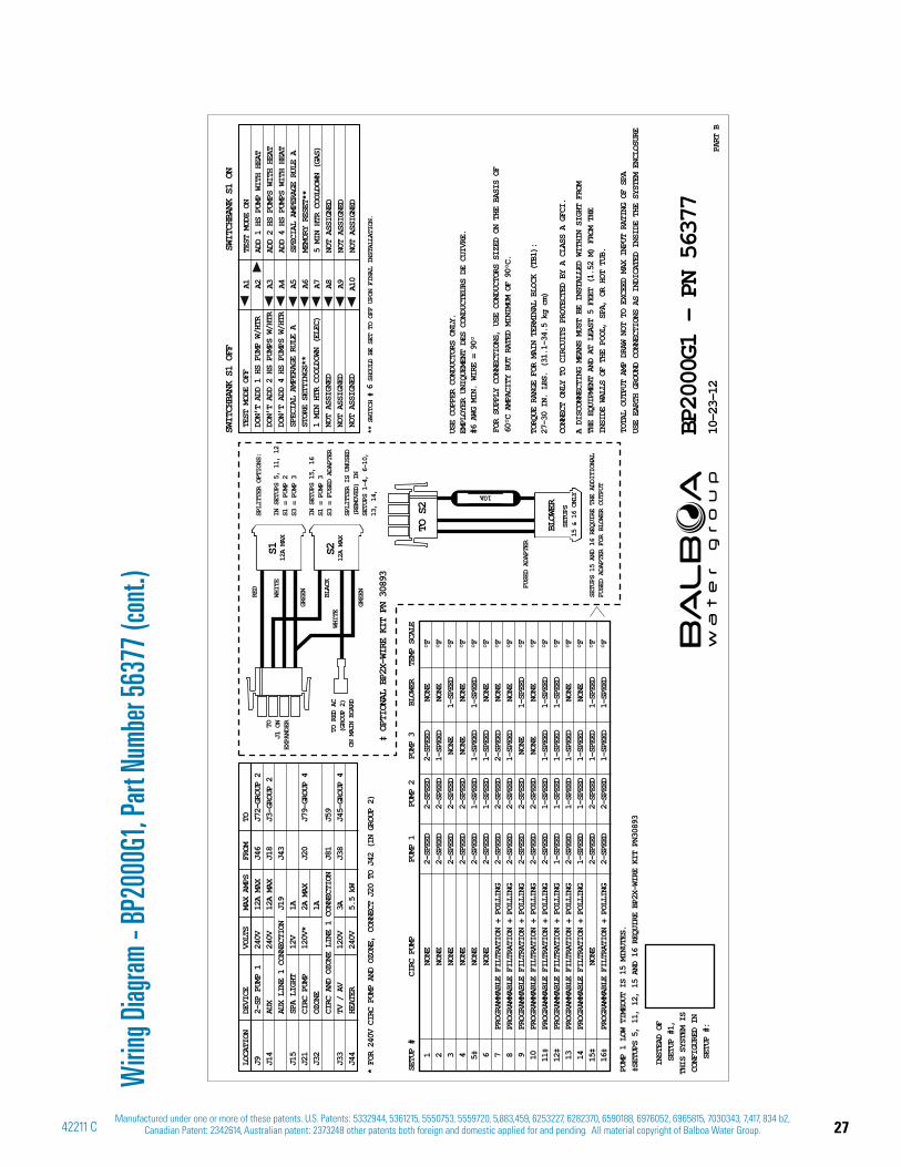
Wirin
g Diag
ram -
BP20
00G1
, Par
t Num
ber 5
6377
(con
t.)
A1 A2 A3 A4 A5 A6 A7 A8 A9 A10
SWITCH
BANK S1 OFF
SWITCHBANK S1 ON
PART B
BP2000G1 – PN 56377
10-23-
12
USE EARTH GROUND CONNECTIONS AS INDICATED INSIDE THE SYSTEM ENCLOSURE
TOTAL
OUTPUT AMP DRAW NOT TO EXCEED MAX INPUT RATING OF SPA
A DISC
ONNECTING MEANS MUST BE INSTALLED WITHIN SIGHT FROM
THE EQ
UIPMENT AND AT LEAST 5 FEET (1.52 M) FROM THE
INSIDE
WALLS OF THE POOL, SPA, OR HOT TUB.
CONNEC
T ONLY TO CIRCUITS PROTECTED BY A CLASS A GFCI.
FOR SU
PPLY CONNECTIONS, USE CONDUCTORS SIZED ON THE BASIS OF
60°C A
MPACITY BUT RATED MINIMUM OF 90°C.
TORQUE RANGE FOR MAIN TERMINAL BLOCK (TB1):
27-30 IN. LBS. (31.1-34.5 kg cm)
USE CO
PPER CONDUCTORS ONLY.
EMPLOY
ER UNIQUEMENT DES CONDUCTEURS DE CUIVRE.
#6 AWG
MIN. WIRE = 90°
1
NONE
2-SPEED
2-SPEED
2-SPEED
NONE
°F
2 NONE
2-SPEED
2-SPEED
1-SPEED
NONE
°F
3
NONE
2-SPEED
2-SPEED
NONE
1-SPEED
°F
4
NONE
2-SPEED
2-SPEED
NONE
NONE
°F
5‡
NONE
2-SPEED
1-SPEED
1-SPEED
1-SPEED
°F
6
NONE
2-SPEED
1-SPEED
1-SPEED
NONE
°F
7
PROGRAMMABLE FILTRATION + POLLING
2-SPEED
2-SPEED
2-SPEED
NONE
°F
8
PROGRAMMABLE FILTRATION + POLLING
2-SPEED
2-SPEED
1-SPEED
NONE
°F
9
PROGRAMMABLE FILTRATION + POLLING
2-SPEED
2-SPEED
NONE
1-SPEED
°F
10
PROGRAMMABLE FILTRATION + POLLING
2-SPEED
2-SPEED
NONE
NONE
°F
11‡
PROGRAMMABLE FILTRATION + POLLING
2-SPEED
1-SPEED
1-SPEED
1-SPEED
°F
12‡
PROGRAMMABLE FILTRATION + POLLING
1-SPEED
1-SPEED
1-SPEED
1-SPEED
°F
13
PROGRAMMABLE FILTRATION + POLLING
2-SPEED
1-SPEED
1-SPEED
NONE
°F
14
PROGRAMMABLE FILTRATION + POLLING
1-SPEED
1-SPEED
1-SPEED
NONE
°F
15‡
NONE
2-SPEED
2-SPEED
1-SPEED
1-SPEED
°F
16‡
PROGRAMMABLE FILTRATION + POLLING
2-SPEED
2-SPEED
1-SPEED
1-SPEED
°F
SETUP #
CIRC PUMP
PUMP 1
PUMP 2
PUMP 3
BLOWER
TEMP SCALE
* FOR 240V CIRC PUMP AND OZONE, CONNECT J20 TO J42 (IN GROUP 2)
INSTEAD OF
SETUP #1,
THIS SYSTEM IS
CONFIGURED IN
SETUP #:
PUMP 1 LOW TIMEOUT IS 15 MINUTES.
‡SETUPS 5, 11, 12, 15 AND 16 REQUIRE BP2X-WIRE KIT PN30893
LOCATION
DEVICE
VOLTS
MAX AMPS
FROM
TOJ9
2-SP PUMP 1
240V
12A MAX
J46
J72-GROUP 2
J14
AUX
240V
12A MAX
J18
J3-GROUP 2
AUX LINE 1 CONNECTION
J19
J43
J15
SPA
LIGHT
12V
1A
J21
CIRC PUMP
120V*
2A MAX
J20
J79-GROUP 4
J32
OZONE
1A
CIRC AND OZONE LINE 1 CONNECTION
J81
J59
J33
TV / AV
120V
3A
J38
J45-GROUP 4
J44
HEATER
240V
5.5 kW
TOJ1 ON
EXPANDER
TO RED AC
(GROUP 2)
ON MAIN BOARD
SPLITTER OPTIONS:
IN SETUPS 5, 11, 12
S1 = PUMP 2
S3 = PUMP 3
IN SETUPS 15, 16
S1 = PUMP 3
S3 = FUSED ADAPTER
SPLITTER IS UNUSED
(REMOVED) IN
SETUPS 1-4, 6-10,
13, 14,
SETUPS 15 AND 16 REQUIRE THE ADDITIONAL
FUSED ADAPTER FOR BLOWER OUTPUT
WHITE
RED
WHITE
GREEN
GREEN
BLACK
S112A MAX
S212A MAX
FUSED ADAPTER
‡ OPTIONAL BP2X-WIRE KIT PN 30893
TO S2
SETUPS
15 & 16 ONLY
BLOWER
10A
TEST MODE OFF
DON’T ADD 1 HS PUMP W/HTR
DON’T ADD 2 HS PUMPS W/HTR
DON’T ADD 4 HS PUMPS W/HTR
SPECIAL AMPERAGE RULE A
STORE SETTINGS**
1 MIN HTR COOLDOWN (ELEC)
NOT ASSIGNED
NOT ASSIGNED
NOT ASSIGNED
TEST MODE ON
ADD 1 HS PUMP WITH HEAT
ADD 2 HS PUMPS WITH HEAT
ADD 4 HS PUMPS WITH HEAT
SPECIAL AMPERAGE RULE A
MEMORY RESET**
5 MIN HTR COOLDOWN (GAS)
NOT ASSIGNED
NOT ASSIGNED
NOT ASSIGNED
** SWITCH # 6
SHOULD BE SET TO OFF UPON FINAL INSTALLATION.
28 Manufactured under one or more of these patents. U.S. Patents: 5332944, 5361215, 5550753, 5559720, 5,883,459, 6253227, 6282370, 6590188, 6976052, 6965815, 7030343, 7,417, 834 b2, Canadian Patent: 2342614, Australian patent: 2373248 other patents both foreign and domestic applied for and pending. All material copyright of Balboa Water Group. 6/22/13
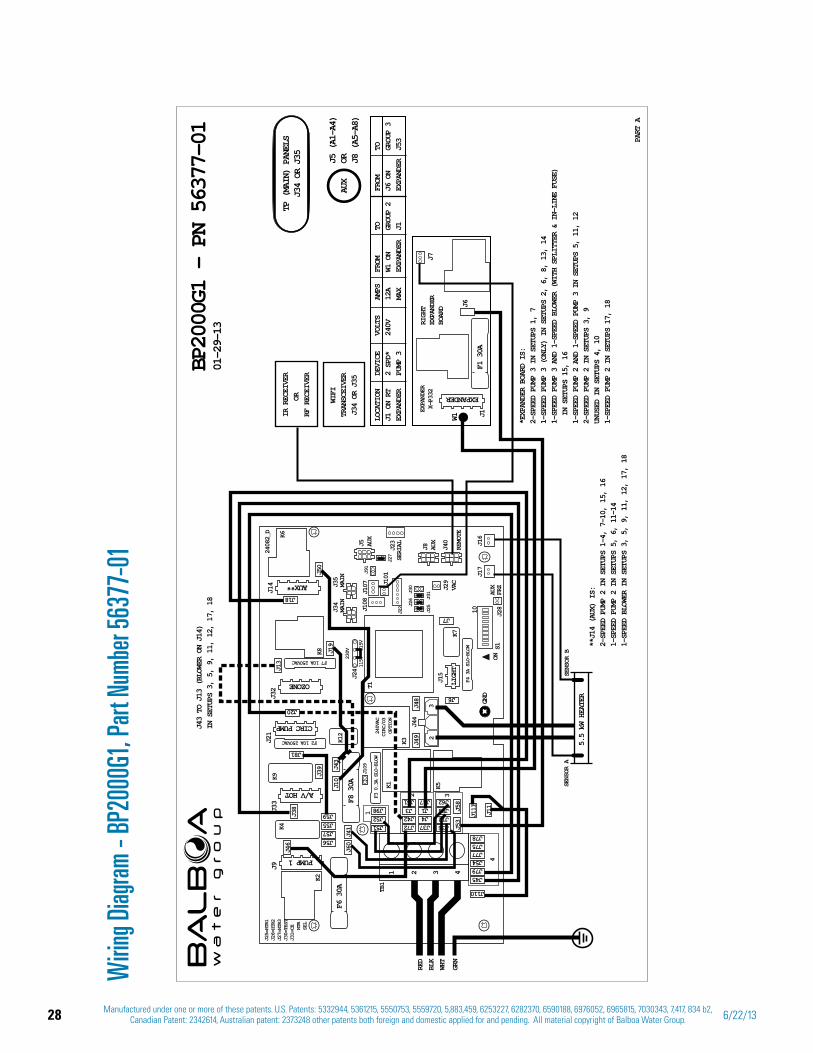
Wirin
g Diag
ram -
BP20
00G1
, Par
t Num
ber 5
6377
-01
F4 3A SLO-BLOW
J25
J31
J26
J30
115V
115V
230V
F3 0.3A SLO-BLOW
J25=HTR1
J26=HTR2
J27=HTR3
J30=TEST
J31=CE
HTR
SEL
F7 10A 250VAC
F2 10A 250VAC
J44
3
TB1
J15
ON
10
S1
K5K1
K3
T1
K2
K4
K8
LIGH
T
GND
J33
J21
J32
J9
1 2 3 4
2
K6
4
32
1
J45
J110
J79J54
J72J42J3
J37J4J1
J61 J47
J77J75J78
J36
J60
J46
J38
J39
J111
J53
J58
J11
J41
J48 J6
J7
J49
J19
J50
J13
J12J88J62
F6 30A
F8 30A
J56J57J55J59
J51J52J98
J10
J81
J20
J18
J43
CIRC PUMP
OZONE
A/V HOT
PUMP 1
J14
K9
J5 AUX
J8 AUX
J40
REMOTE
J35
MAIN
J34
MAIN
J109
J27
J91
J22
J23
SERIAL
J29
VAC
J28
AUX
FRZ
J17
J16
24082_D
J101
J108
J24
J107
K12
K7
TP (
MAIN
) PA
NELS
J34
OR J
35
01-2
9-13
BP2000G1 – PN 56377-01 PA
RT A
AUX
J5 (
A1-A
4)OR J8
(A5
-A8)
GRN
WHT
RED
BLK
SENSOR B
SENSOR A
5.5 kW HEATER
EXPANDER
LOCATION
DEVICE
VOLTS
AMPS
FROM
TO
FROM
TOJ1 ON RT
2 SPD*
240V
12A
W1 ON
GROUP 2
J6 ON
GROUP 3
EXPANDER
PUMP 3
MAX
EXPANDER
J1
EXPANDER
J53
*EXPANDER BOARD IS:
2-SPEED PUMP 3 IN SETUPS 1, 7
1-SPEED PUMP 3 (ONLY) IN SETUPS 2, 6, 8, 13, 14
1-SPEED PUMP 3 AND 1-SPEED BLOWER (WITH SPLITTER & IN-LINE FUSE)
IN SETUPS 15, 16
1-SPEED PUMP 2 AND 1-SPEED PUMP 3 IN SETUPS 5, 11, 12
2-SPEED PUMP 2 IN SETUPS 3, 9
UNUSED IN SETUPS 4, 10
1-SPEED PUMP 2 IN SETUPS 17, 18
J1W1
J7RIGHT
EXPANDER
BOARD J6
EXPANDER
X-P332
F1 30A
J43 TO J13 (BLOWER ON J14)
IN SETUPS 3, 5, 9, 11, 12, 17, 18
240VAC
CIRC/O3
OPTION
AUX**
**J14 (AUX) IS:
2-SPEED PUMP 2 IN SETUPS 1-4, 7-10, 15, 16
1-SPEED PUMP 2 IN SETUPS 5, 6, 11–14
1-SPEED BLOWER IN SETUPS 3, 5, 9, 11, 12, 17, 18
WIFI
TRANSCEIVER
J34 OR J35
IR RECEIVER
OR
RF RECEIVER
29Manufactured under one or more of these patents. U.S. Patents: 5332944, 5361215, 5550753, 5559720, 5,883,459, 6253227, 6282370, 6590188, 6976052, 6965815, 7030343, 7,417, 834 b2,
Canadian Patent: 2342614, Australian patent: 2373248 other patents both foreign and domestic applied for and pending. All material copyright of Balboa Water Group.42211 C
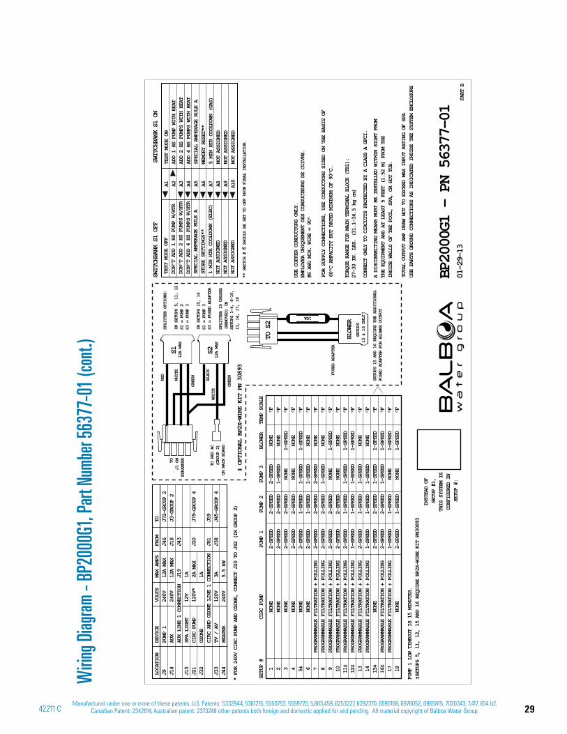
Wirin
g Diag
ram -
BP20
00G1
, Par
t Num
ber 5
6377
-01 (
cont
.)
A1 A2 A3 A4 A5 A6 A7 A8 A9 A10
SWITCH
BANK S1 OFF
SWITCHBANK S1 ON
PART B
BP2000G1 – PN 56377-01
01-2
9-13
USE EARTH GROUND CONNECTIONS AS INDICATED INSIDE THE SYSTEM ENCLOSURE
TOTAL OU
TPUT AMP DRAW NOT TO EXCEED MAX INPUT RATING OF SPA
A DISCON
NECTING MEANS MUST BE INSTALLED WITHIN SIGHT FROM
THE EQUI
PMENT AND AT LEAST 5 FEET (1.52 M) FROM THE
INSIDE W
ALLS OF THE POOL, SPA, OR HOT TUB.
CONNECT
ONLY TO CIRCUITS PROTECTED BY A CLASS A GFCI.
FOR SUPP
LY CONNECTIONS, USE CONDUCTORS SIZED ON THE BASIS OF
60°C AMP
ACITY BUT RATED MINIMUM OF 90°C.
TORQUE RANGE FOR MAIN TERMINAL BLOCK (TB1):
27-30 IN. LBS. (31.1-34.5 kg cm)
USE COPP
ER CONDUCTORS ONLY.
EMPLOYER
UNIQUEMENT DES CONDUCTEURS DE CUIVRE.
#6 AWG M
IN. WIRE = 90°
1
NONE
2-SPEED
2-SPEED
2-SPEED
NONE
°F
2 NONE
2-SPEED
2-SPEED
1-SPEED
NONE
°F
3
NONE
2-SPEED
2-SPEED
NONE
1-SPEED
°F
4
NONE
2-SPEED
2-SPEED
NONE
NONE
°F
5‡
NONE
2-SPEED
1-SPEED
1-SPEED
1-SPEED
°F
6
NONE
2-SPEED
1-SPEED
1-SPEED
NONE
°F
7
PROGRAMMABLE FILTRATION + POLLING
2-SPEED
2-SPEED
2-SPEED
NONE
°F
8
PROGRAMMABLE FILTRATION + POLLING
2-SPEED
2-SPEED
1-SPEED
NONE
°F
9
PROGRAMMABLE FILTRATION + POLLING
2-SPEED
2-SPEED
NONE
1-SPEED
°F
10
PROGRAMMABLE FILTRATION + POLLING
2-SPEED
2-SPEED
NONE
NONE
°F
11‡
PROGRAMMABLE FILTRATION + POLLING
2-SPEED
1-SPEED
1-SPEED
1-SPEED
°F
12‡
PROGRAMMABLE FILTRATION + POLLING
1-SPEED
1-SPEED
1-SPEED
1-SPEED
°F
13
PROGRAMMABLE FILTRATION + POLLING
2-SPEED
1-SPEED
1-SPEED
NONE
°F
14
PROGRAMMABLE FILTRATION + POLLING
1-SPEED
1-SPEED
1-SPEED
NONE
°F
15‡
NONE
2-SPEED
2-SPEED
1-SPEED
1-SPEED
°F
16‡
PROGRAMMABLE FILTRATION + POLLING
2-SPEED
2-SPEED
1-SPEED
1-SPEED
°F
17
PROGRAMMABLE FILTRATION + POLLING
1-SPEED
1-SPEED
NONE
1-SPEED
°F
18
NONE
2-SPEED
1-SPEED
NONE
1-SPEED
°F
SETUP #
CIRC PUMP
PUMP 1
PUMP 2
PUMP 3
BLOWER
TEMP SCALE
* FOR 240V CIRC PUMP AND OZONE, CONNECT J20 TO J42 (IN GROUP 2) IN
STEAD OF
SETU
P #1,
THIS S
YSTEM IS
CONFIG
URED IN
SETUP #:
PUMP 1 LOW TIMEOUT IS 15 MINUTES.
‡SETUPS 5, 11, 12, 15 AND 16 REQUIRE BP2X-WIRE KIT PN30893
LOCATION
DEVICE
VOLTS
MAX AMPS
FROM
TOJ9
PUMP 1
240V
12A MAX
J46
J72-GROUP 2
J14
AUX
240V
12A MAX
J18
J3-GROUP 2
AUX LINE 1 CONNECTION
J19
J43
J15
SPA LIGHT
12V
1A
J21
CIRC PUMP
120V*
2A MAX
J20
J79-GROUP 4
J32
OZONE
1A
CIRC AND OZONE LINE 1 CONNECTION
J81
J59
J33
TV / AV
120V
3A
J38
J45-GROUP 4
J44
HEATER
240V
5.5 kW
TOJ1 ON
EXPANDER
TO RED AC
(GROUP 2)
ON MAIN BOARD
SPLITTER OPTIONS:
IN SETUPS 5, 11, 12
S1 = PUMP 2
S3 = PUMP 3
IN SETUPS 15, 16
S1 = PUMP 3
S3 = FUSED ADAPTER
SPLITTER IS UNUSED
(REMOVED) IN
SETUPS 1-4, 6-10,
13, 14, 17, 18
SETUPS 15 AND 16 REQUIRE THE ADDITIONAL
FUSED ADAPTER FOR BLOWER OUTPUT
WHITE
RED
WHITE
GREEN
GREEN
BLACK
S112A MAX
S212A MAX
FUSED ADAPTER
‡ OPTIONAL BP2X-WIRE KIT PN 30893
TO S2
SETUPS
15 & 16 ONLY
BLOWER
10A
TEST MODE OFF
DON’T ADD 1 HS PUMP W/HTR
DON’T ADD 2 HS PUMPS W/HTR
DON’T ADD 4 HS PUMPS W/HTR
SPECIAL AMPERAGE RULE A
STORE SETTINGS**
1 MIN HTR COOLDOWN (ELEC)
NOT ASSIGNED
NOT ASSIGNED
NOT ASSIGNED
TEST MODE ON
ADD 1 HS PUMP WITH HEAT
ADD 2 HS PUMPS WITH HEAT
ADD 4 HS PUMPS WITH HEAT
SPECIAL AMPERAGE RULE A
MEMORY RESET**
5 MIN HTR COOLDOWN (GAS)
NOT ASSIGNED
NOT ASSIGNED
NOT ASSIGNED
** SWITCH # 6
SHOULD BE SET TO OFF UPON FINAL INSTALLATION.
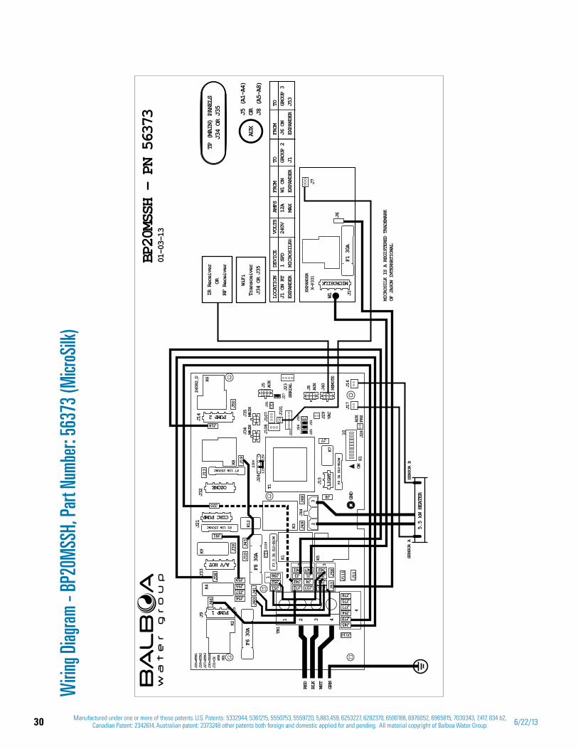
30 Manufactured under one or more of these patents. U.S. Patents: 5332944, 5361215, 5550753, 5559720, 5,883,459, 6253227, 6282370, 6590188, 6976052, 6965815, 7030343, 7,417, 834 b2, Canadian Patent: 2342614, Australian patent: 2373248 other patents both foreign and domestic applied for and pending. All material copyright of Balboa Water Group. 6/22/13
Wirin
g Diag
ram -
BP20
MSS
H, P
art N
umbe
r: 56
373 (
Micr
oSilk
)
TP (
MAIN
) PA
NELS
J34
OR J
35
01-0
3-13
F4 3A SLO-BLOW
J25
J31
J26
J30
115V
115V
230V
F3 0.3A SLO-BLOW
J25=HTR1
J26=HTR2
J27=HTR3
J30=TEST
J31=CE
HTR
SEL
F7 10A 250VAC
F2 10A 250VAC
J44
3
TB1
J15
ON
10
S1
K5K1
K3
T1
K2
K4
K8
LIGH
T
GND
J33
J21
J32
J9
1 2 3 4
2
K6
4
32
1
J45
J110
J79J54
J72J42J3
J37J4J1
J61 J47
J77J75J78
J36
J60
J46
J38
J39
J111
J53
J58
J11
J41
J48 J6
J7J49
J19
J50
J13
J12J88J62
F6 30A
F8 30A
J56J57J55J59
J51J52J98
J10
J81
J20
J18
J43
CIRC PUMP
OZONE
A/V HOT
PUMP 1
J14
K9
J5 AUX
J8 AUX
J40
REMOTE
J35
MAIN
J34
MAIN
J109
J27
J91
J22
J23
SERIAL
J29
VAC
J28
AUX
FRZ
J17
J16
24082_D
J101
J108
J24
J107
K12
K7
AUX
J5 (
A1-A
4)OR J8
(A5
-A8)
GRN
WHT
RED
BLK
BP20MSSH – PN 56373
SENSOR B
SENSOR A
5.5 kW HEATER
MICROSILK
LOCATION
DEVICE
VOLTS
AMPS
FROM
TO
FROM
TOJ1 ON RT
1 SPD
240V
12A
W1 ON
GROUP 2
J6 ON
GROUP 3
EXPANDER
MICROSILK®
MAX
EXPANDER
J1
EXPANDER
J53
J1W1
J7
J6
EXPANDER
X-P331
F1 30A
MICROSILK IS A REGISTERED TRADEMARK
OF JASON INTERNATIONAL
PUMP 2
WiFi
Transceiver
J34 OR J35
IR Receiver
OR
RF Receiver
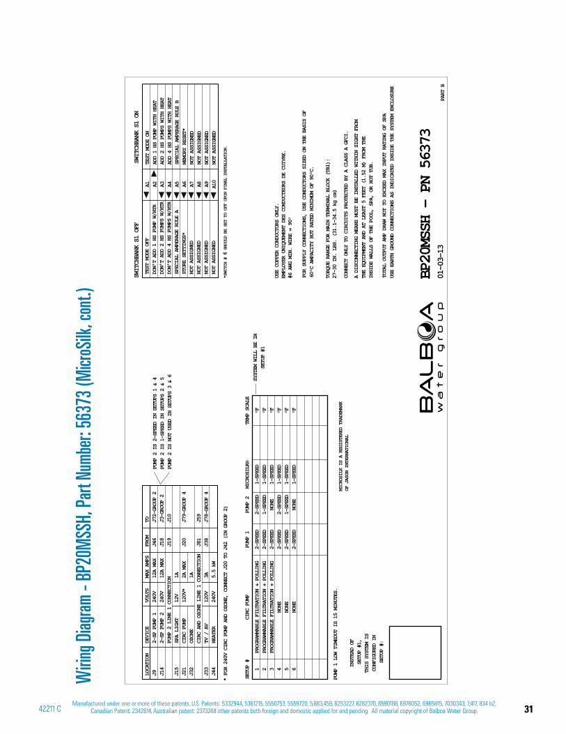
31Manufactured under one or more of these patents. U.S. Patents: 5332944, 5361215, 5550753, 5559720, 5,883,459, 6253227, 6282370, 6590188, 6976052, 6965815, 7030343, 7,417, 834 b2,
Canadian Patent: 2342614, Australian patent: 2373248 other patents both foreign and domestic applied for and pending. All material copyright of Balboa Water Group.42211 C
A1 A2 A3 A4 A5 A6 A7 A8 A9 A10
SWITCH
BANK S1 OFF
SWITCHBANK S1 ON
PART B
BP20MSSH – PN 56373
01-0
3-13
USE EARTH GROUND CONNECTIONS AS INDICATED INSIDE THE SYSTEM ENCLOSURE
TOTAL OU
TPUT AMP DRAW NOT TO EXCEED MAX INPUT RATING OF SPA
A DISCON
NECTING MEANS MUST BE INSTALLED WITHIN SIGHT FROM
THE EQUI
PMENT AND AT LEAST 5 FEET (1.52 M) FROM THE
INSIDE W
ALLS OF THE POOL, SPA, OR HOT TUB.
CONNECT
ONLY TO CIRCUITS PROTECTED BY A CLASS A GFCI.
FOR SUPP
LY CONNECTIONS, USE CONDUCTORS SIZED ON THE BASIS OF
60°C AMP
ACITY BUT RATED MINIMUM OF 90°C.
TORQUE RANGE FOR MAIN TERMINAL BLOCK (TB1):
27-30 IN. LBS. (31.1-34.5 kg cm)
USE COPP
ER CONDUCTORS ONLY.
EMPLOYER
UNIQUEMENT DES CONDUCTEURS DE CUIVRE.
#6 AWG M
IN. WIRE = 90°
1
PROGRAMMABLE FILTRATION + POLLING
2-SPEED
2-SPEED
1-SPEED
°F
2
PROGRAMMABLE FILTRATION + POLLING
2-SPEED
1-SPEED
1-SPEED
°F
3
PROGRAMMABLE FILTRATION + POLLING
2-SPEED
NONE
1-SPEED
°F
4
NONE
2-SPEED
2-SPEED
1-SPEED
°F
5
NONE
2-SPEED
1-SPEED
1-SPEED
°F
6
NONE
2-SPEED
NONE
1-SPEED
°F
SETUP #
CIRC PUMP
PUMP 1
PUMP 2
MICROSILK®
TEMP SCALE
SYSTEM WILL BE IN
SETUP #1
INSTEAD OF
SETUP #1,
THIS SYSTEM IS
CONFIGURED IN
SETUP #:
PUMP 1 LOW TIMEOUT IS 15 MINUTES.
PUMP 2 IS 2-SPEED IN SETUPS 1 & 4
PUMP 2 IS 1-SPEED IN SETUPS 2 & 5
PUMP 2 IS NOT USED IN SETUPS 3 & 6
LOCATION
DEVICE
VOLTS
MAX AMPS
FROM
TOJ9
2-SP PUMP 1
240V
12A MAX
J46
J72-GROUP 2
J14
2-SP PUMP 2
240V
12A MAX
J18
J3-GROUP 2
PUMP 2 LINE 1 CONNECTION
J19
J10
J15
SPA LIGHT
12V
1A
J21
CIRC PUMP
120V*
2A MAX
J20
J79-GROUP 4
J32
OZONE
1A
CIRC AND OZONE LINE 1 CONNECTION
J81
J59
J33
TV / AV
120V
3A
J38
J78-GROUP 4
J44
HEATER
240V
5.5 kW
* FOR 240V CIRC PUMP AND OZONE, CONNECT J20 TO J42 (IN GROUP 2)
MICROSILK IS A REGISTERED TRADEMARK
OF JASON INTERNATIONAL
TEST MODE OFF
DON’T ADD 1 HS PUMP W/HTR
DON’T ADD 2 HS PUMPS W/HTR
DON’T ADD 4 HS PUMPS W/HTR
SPECIAL AMPERAGE RULE A
STORE SETTINGS*
NOT ASSIGNED
NOT ASSIGNED
NOT ASSIGNED
NOT ASSIGNED
TEST MODE ON
ADD 1 HS PUMP WITH HEAT
ADD 2 HS PUMPS WITH HEAT
ADD 4 HS PUMPS WITH HEAT
SPECIAL AMPERAGE RULE B
MEMORY RESET*
NOT ASSIGNED
NOT ASSIGNED
NOT ASSIGNED
NOT ASSIGNED
*SWITCH # 6
SHOULD BE SET TO OFF UPON FINAL INSTALLATION.
Wirin
g Diag
ram -
BP20
MSS
H, P
art N
umbe
r: 56
373 (
Micr
oSilk
, con
t.)
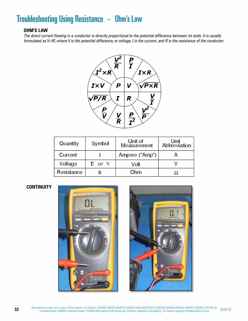
32 Manufactured under one or more of these patents. U.S. Patents: 5332944, 5361215, 5550753, 5559720, 5,883,459, 6253227, 6282370, 6590188, 6976052, 6965815, 7030343, 7,417, 834 b2, Canadian Patent: 2342614, Australian patent: 2373248 other patents both foreign and domestic applied for and pending. All material copyright of Balboa Water Group. 6/22/13
OHM’S LAWThe direct current flowing in a conductor is directly proportional to the potential difference between its ends. It is usually formulated as V=IR, where V is the potential difference, or voltage, I is the current, and R is the resistance of the conductor.
Ohm’s Law
CONTINUITY
Troubleshooting Using Resistance -

33Manufactured under one or more of these patents. U.S. Patents: 5332944, 5361215, 5550753, 5559720, 5,883,459, 6253227, 6282370, 6590188, 6976052, 6965815, 7030343, 7,417, 834 b2,
Canadian Patent: 2342614, Australian patent: 2373248 other patents both foreign and domestic applied for and pending. All material copyright of Balboa Water Group.42211 C
Testing a Fuse: Continuity
TESTING A FUSE: CHECK CONTINUITY WITH THE FUSE REMOVED
A FUSE WITH THE METER READING “GOOD”
A FUSE WITH THE METER READING “BAD”
FUSES USED ON BP SPA SYSTEMSFuse BWG Part Number
30A 30136
10A 30122
3A Slo-Blo 20600
0.3A Slo-Blo 21581
0.15A Slo-Blo 26281
0.125A Slo-Blo 26397
THE PREFERRED WAY TO CHECK FOR FUSE CONTINUITY IS WITH THE FUSES REMOVED FROM THE CIRCUIT.
NOTE: THERE ARE NO SERVICEABLE PARTS ON THE PCB.
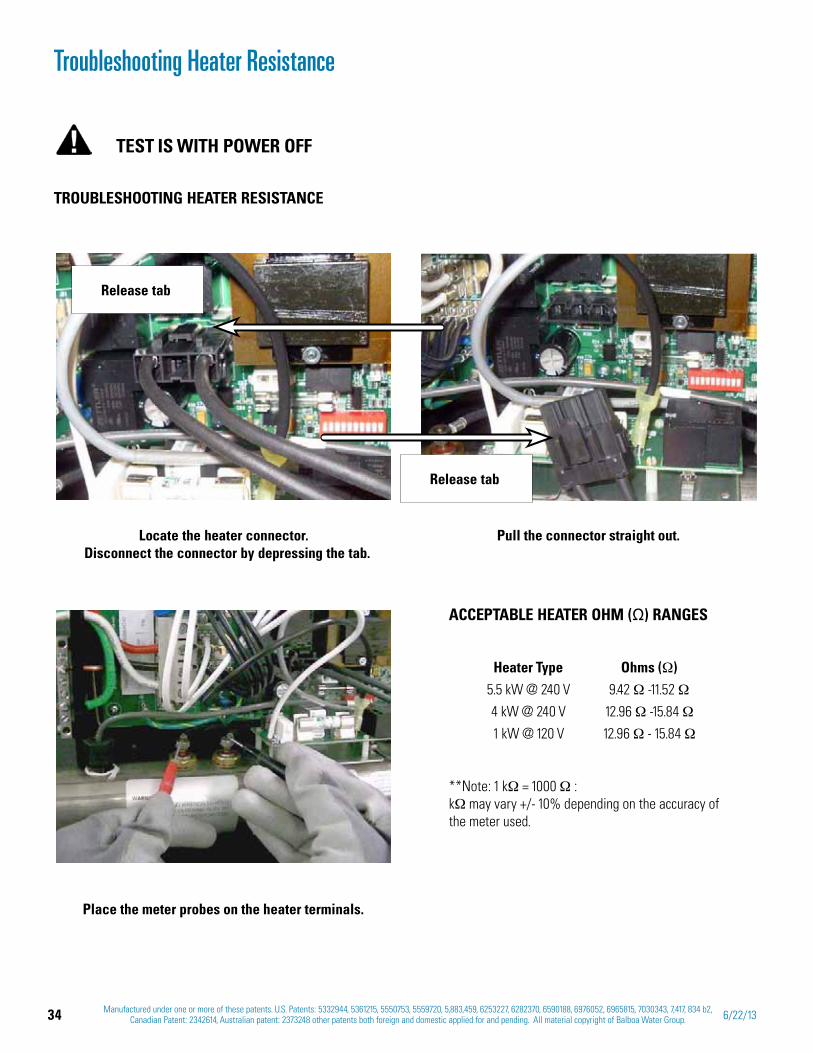
34 Manufactured under one or more of these patents. U.S. Patents: 5332944, 5361215, 5550753, 5559720, 5,883,459, 6253227, 6282370, 6590188, 6976052, 6965815, 7030343, 7,417, 834 b2, Canadian Patent: 2342614, Australian patent: 2373248 other patents both foreign and domestic applied for and pending. All material copyright of Balboa Water Group. 6/22/13
Troubleshooting Heater Resistance
TROUBLESHOOTING HEATER RESISTANCE
Locate the heater connector. Disconnect the connector by depressing the tab.
Pull the connector straight out.
Place the meter probes on the heater terminals.
Release tab
Release tab
ACCEPTABLE HEATER OHM ( ) RANGES
Heater Type Ohms ( ) 5.5 kW @ 240 V 9.42 -11.52
4 kW @ 240 V 12.96 -15.84
1 kW @ 120 V 12.96 - 15.84
**Note: 1 k = 1000 : k may vary +/- 10% depending on the accuracy of the meter used.
TEST IS WITH POWER OFF
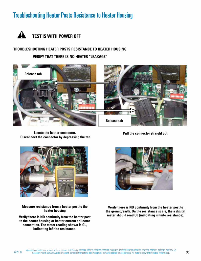
35Manufactured under one or more of these patents. U.S. Patents: 5332944, 5361215, 5550753, 5559720, 5,883,459, 6253227, 6282370, 6590188, 6976052, 6965815, 7030343, 7,417, 834 b2,
Canadian Patent: 2342614, Australian patent: 2373248 other patents both foreign and domestic applied for and pending. All material copyright of Balboa Water Group.42211 C
TEST IS WITH POWER OFF
TROUBLESHOOTING HEATER POSTS RESISTANCE TO HEATER HOUSING
VERIFY THAT THERE IS NO HEATER “LEAKAGE”
Measure resistance from a heater post to the heater housing
Verify there is NO continuity from the heater post to the heater housing or heater current collector
connection. The meter reading shown is OL, indicating infinite resistance.
Verify there is NO continuity from the heater post to the ground/earth. On the resistance scale, the a digital meter should read OL (indicating infinite resistance).
Troubleshooting Heater Posts Resistance to Heater Housing
Locate the heater connector. Disconnect the connector by depressing the tab.
Pull the connector straight out.
Release tab
Release tab

36 Manufactured under one or more of these patents. U.S. Patents: 5332944, 5361215, 5550753, 5559720, 5,883,459, 6253227, 6282370, 6590188, 6976052, 6965815, 7030343, 7,417, 834 b2, Canadian Patent: 2342614, Australian patent: 2373248 other patents both foreign and domestic applied for and pending. All material copyright of Balboa Water Group. 6/22/13
Troubleshooting with Voltage
WHEN TESTING VOLTAGE WHEN TESTING AMPERAGE
IMPORTANT!
BEFORE TESTING A SPA CONTROL SYSTEM FOR VOLTAGE OR AMPERAGE, BE SURE OF THE FOLLOWING DANGERS:
HIGH AND LOW VOLTAGE CAN KILL. QUALIFIED TECHNICIANS SHOULD BE PERFORMING THESE TESTS
OR
OBSERVE SAFETY AT ALL TIMES
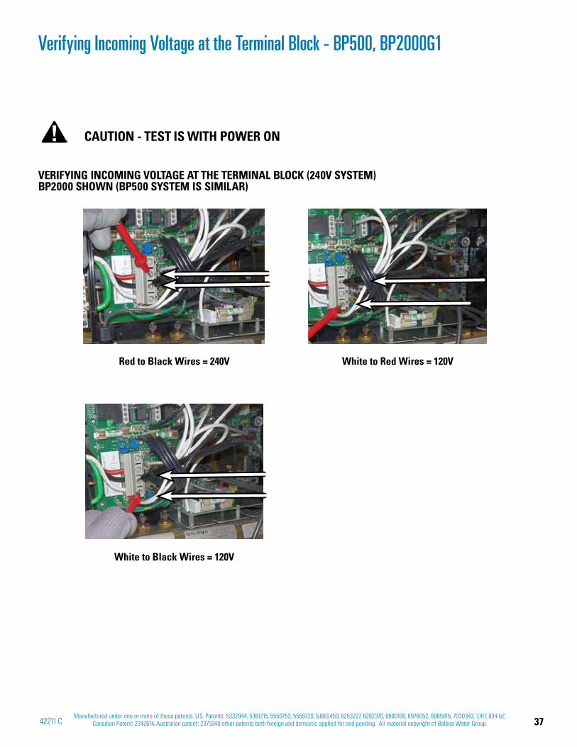
37Manufactured under one or more of these patents. U.S. Patents: 5332944, 5361215, 5550753, 5559720, 5,883,459, 6253227, 6282370, 6590188, 6976052, 6965815, 7030343, 7,417, 834 b2,
Canadian Patent: 2342614, Australian patent: 2373248 other patents both foreign and domestic applied for and pending. All material copyright of Balboa Water Group.42211 C
Verifying Incoming Voltage at the Terminal Block - BP500, BP2000G1
VERIFYING INCOMING VOLTAGE AT THE TERMINAL BLOCK (240V SYSTEM) BP2000 SHOWN (BP500 SYSTEM IS SIMILAR)
CAUTION - TEST IS WITH POWER ON
Red to Black Wires = 240V
White to Black Wires = 120V
White to Red Wires = 120V
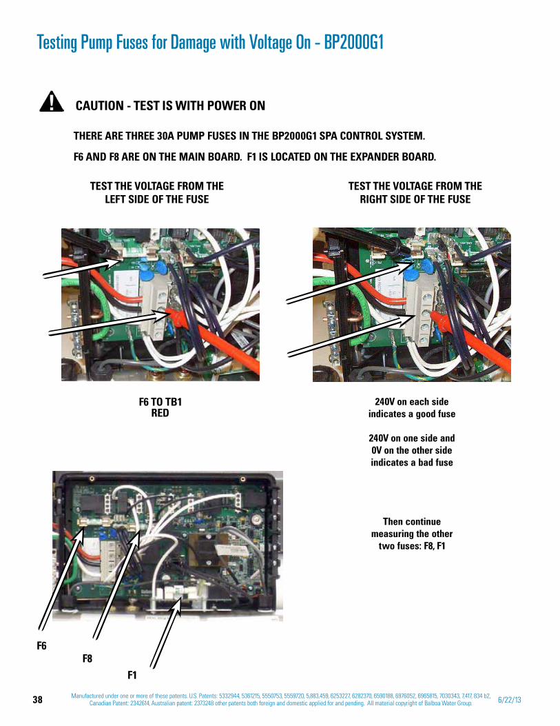
38 Manufactured under one or more of these patents. U.S. Patents: 5332944, 5361215, 5550753, 5559720, 5,883,459, 6253227, 6282370, 6590188, 6976052, 6965815, 7030343, 7,417, 834 b2, Canadian Patent: 2342614, Australian patent: 2373248 other patents both foreign and domestic applied for and pending. All material copyright of Balboa Water Group. 6/22/13
Testing Pump Fuses for Damage with Voltage On - BP2000G1
TEST THE VOLTAGE FROM THE RIGHT SIDE OF THE FUSE
TEST THE VOLTAGE FROM THE LEFT SIDE OF THE FUSE
THERE ARE THREE 30A PUMP FUSES IN THE BP2000G1 SPA CONTROL SYSTEM.
F6 AND F8 ARE ON THE MAIN BOARD. F1 IS LOCATED ON THE EXPANDER BOARD.
CAUTION - TEST IS WITH POWER ON
240V on each side indicates a good fuse
240V on one side and 0V on the other side indicates a bad fuse
Then continue measuring the other
two fuses: F8, F1
F6 TO TB1 RED
F6 F8
F1
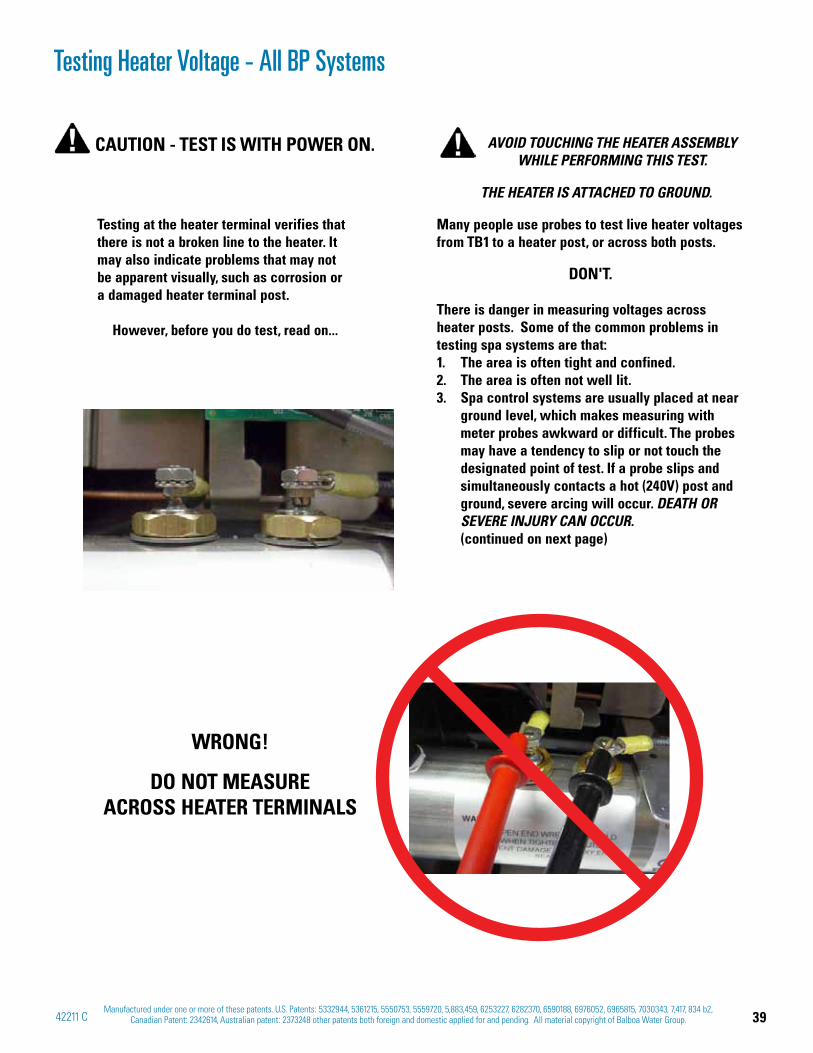
39Manufactured under one or more of these patents. U.S. Patents: 5332944, 5361215, 5550753, 5559720, 5,883,459, 6253227, 6282370, 6590188, 6976052, 6965815, 7030343, 7,417, 834 b2,
Canadian Patent: 2342614, Australian patent: 2373248 other patents both foreign and domestic applied for and pending. All material copyright of Balboa Water Group.42211 C
Testing Heater Voltage - All BP Systems
CAUTION - TEST IS WITH POWER ON.
Testing at the heater terminal verifies that there is not a broken line to the heater. It may also indicate problems that may not be apparent visually, such as corrosion or a damaged heater terminal post.
However, before you do test, read on...
AVOID TOUCHING THE HEATER ASSEMBLY WHILE PERFORMING THIS TEST.
THE HEATER IS ATTACHED TO GROUND.
Many people use probes to test live heater voltages from TB1 to a heater post, or across both posts.
DON'T.
There is danger in measuring voltages across heater posts. Some of the common problems in testing spa systems are that:
The area is often tight and confined. 1. The area is often not well lit.2. Spa control systems are usually placed at near 3. ground level, which makes measuring with meter probes awkward or difficult. The probes may have a tendency to slip or not touch the designated point of test. If a probe slips and simultaneously contacts a hot (240V) post and ground, severe arcing will occur. DEATH OR SEVERE INJURY CAN OCCUR. (continued on next page)
WRONG!
DO NOT MEASURE ACROSS HEATER TERMINALS
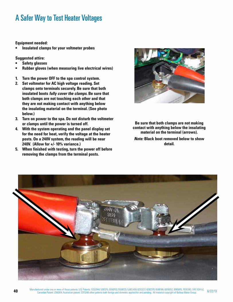
40 Manufactured under one or more of these patents. U.S. Patents: 5332944, 5361215, 5550753, 5559720, 5,883,459, 6253227, 6282370, 6590188, 6976052, 6965815, 7030343, 7,417, 834 b2, Canadian Patent: 2342614, Australian patent: 2373248 other patents both foreign and domestic applied for and pending. All material copyright of Balboa Water Group. 6/22/13
Equipment needed: Insulated clamps for your voltmeter probes
Suggested attire:Safety glassesRubber gloves (when measuring live electrical wires)
Turn the power OFF to the spa control system.1. Set voltmeter for AC high voltage reading. Set 2. clamps onto terminals securely. Be sure that both insulated boots fully cover the clamps. Be sure that both clamps are not touching each other and that they are not making contact with anything below the insulating material on the terminal. (See photo below.)Turn on power to the spa. Do not disturb the voltmeter 3. or clamps until the power is turned off.With the system operating and the panel display set 4. for the need for heat, verify the voltage at the heater posts. On a 240V system, the reading will be near 240V. (Allow for +/- 10% variance.) When finished with testing, turn the power off before 5. removing the clamps from the terminal posts.
A Safer Way to Test Heater Voltages
Be sure that both clamps are not making contact with anything below the insulating
material on the terminal (arrows).
Note: Black boot removed below to show detail.
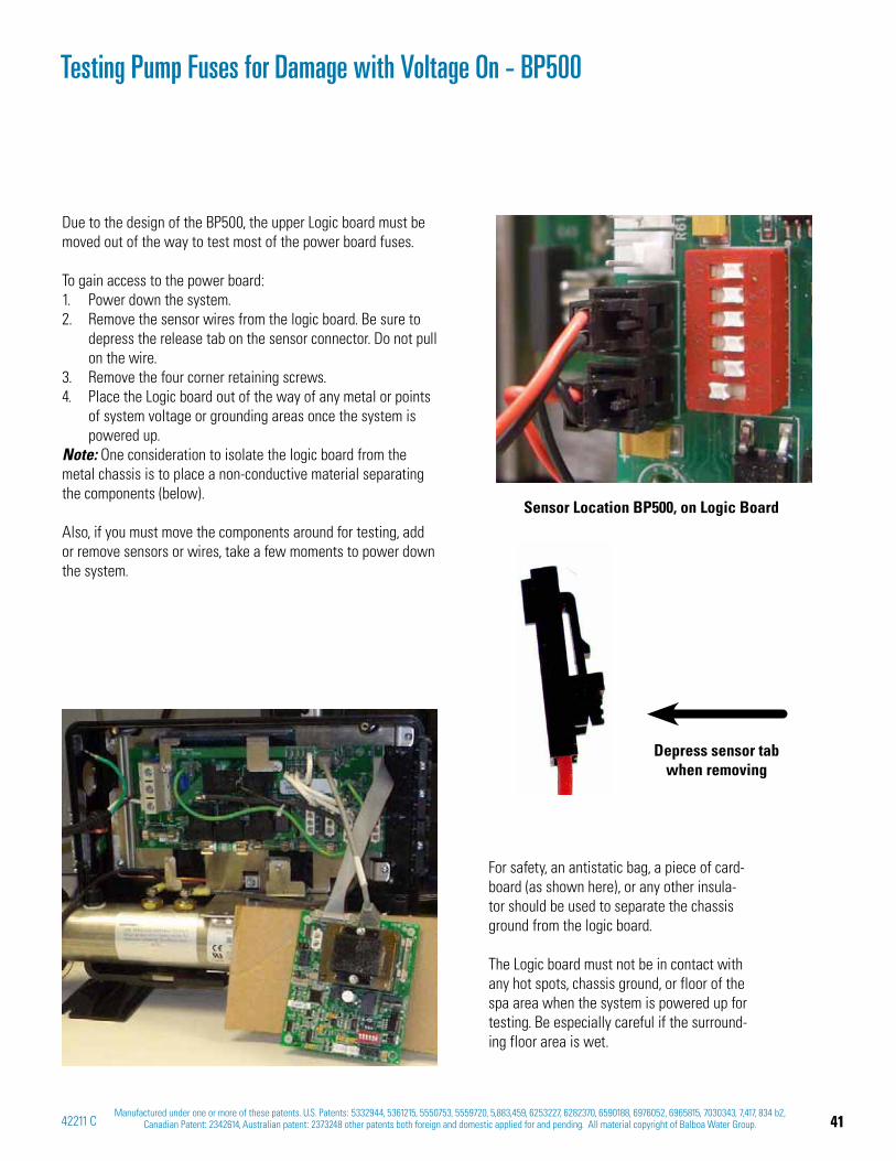
41Manufactured under one or more of these patents. U.S. Patents: 5332944, 5361215, 5550753, 5559720, 5,883,459, 6253227, 6282370, 6590188, 6976052, 6965815, 7030343, 7,417, 834 b2,
Canadian Patent: 2342614, Australian patent: 2373248 other patents both foreign and domestic applied for and pending. All material copyright of Balboa Water Group.42211 C
Testing Pump Fuses for Damage with Voltage On - BP500
Due to the design of the BP500, the upper Logic board must be moved out of the way to test most of the power board fuses.
To gain access to the power board:Power down the system. 1. Remove the sensor wires from the logic board. Be sure to 2. depress the release tab on the sensor connector. Do not pull on the wire.Remove the four corner retaining screws. 3. Place the Logic board out of the way of any metal or points 4. of system voltage or grounding areas once the system is powered up.
Note: One consideration to isolate the logic board from the metal chassis is to place a non-conductive material separating the components (below).
Also, if you must move the components around for testing, add or remove sensors or wires, take a few moments to power down the system.
Sensor Location BP500, on Logic Board
Depress sensor tab when removing
For safety, an antistatic bag, a piece of card-board (as shown here), or any other insula-tor should be used to separate the chassis ground from the logic board.
The Logic board must not be in contact with any hot spots, chassis ground, or floor of the spa area when the system is powered up for testing. Be especially careful if the surround-ing floor area is wet.

42 Manufactured under one or more of these patents. U.S. Patents: 5332944, 5361215, 5550753, 5559720, 5,883,459, 6253227, 6282370, 6590188, 6976052, 6965815, 7030343, 7,417, 834 b2, Canadian Patent: 2342614, Australian patent: 2373248 other patents both foreign and domestic applied for and pending. All material copyright of Balboa Water Group. 6/22/13
AMPERAGE HEATER TEST BP2000G1AMPERAGE HEATER TEST BP500
CAUTION - TEST IS WITH POWER ON
Testing Heater Amperage
ACCEPTABLE HEATER AMPERAGE DRAW RANGESHeater Type 120V Amp Draw 240V Amp Draw
5.5 kW @ 240 V 10.42 A - 12.74 A 20.83 A - 25.48 A
4 kW @ 240 V 7.58 A - 9.26 A 15.15 A -18.52 A
1 kW @ 120 V 7.58 A - 9.26 A -
PLACE CLAMP AROUND ONE HEATER WIRE, AND THEN THE OTHER WIRE.

43Manufactured under one or more of these patents. U.S. Patents: 5332944, 5361215, 5550753, 5559720, 5,883,459, 6253227, 6282370, 6590188, 6976052, 6965815, 7030343, 7,417, 834 b2,
Canadian Patent: 2342614, Australian patent: 2373248 other patents both foreign and domestic applied for and pending. All material copyright of Balboa Water Group.42211 C
Testing Low Speed and High Speed at the AMP Pump Connector
WITH THE PUMP LOW SPEED ON, TAKE A VOLTAGE READING AT THE
AMP RECEPTACLE ON THE PCB
THIS WOULD TYPICALLY SHOW LOW SPEED VOLTAGE FOR PUMP ONE. (240V)
WITH THE PUMP HIGH SPEED ON, TAKE A VOLTAGE READING AT THE
AMP RECEPTACLE ON THE PCB
THIS WOULD TYPICALLY SHOW HIGH SPEED VOLTAGE FOR PUMP ONE. (240V)
Ground
Neutral (Common)
Typically Line voltage for 2-speed pumps
Typically Line voltage
Note flat sides in connector
Board Connector Key
Note: These are typical settings only. Voltages may be different depending
on the configuration that the system is set to. See the system's Tech Sheet for
complete information.
PUMP 1 AMP CORD
TESTING LOW SPEED AND HIGH SPEED AT THE AMP CONNECTOR
CAUTION - TEST IS WITH POWER ON
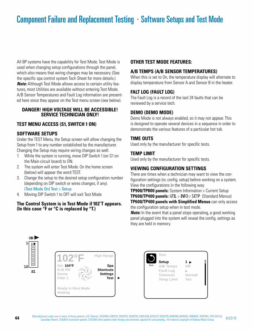
44 Manufactured under one or more of these patents. U.S. Patents: 5332944, 5361215, 5550753, 5559720, 5,883,459, 6253227, 6282370, 6590188, 6976052, 6965815, 7030343, 7,417, 834 b2, Canadian Patent: 2342614, Australian patent: 2373248 other patents both foreign and domestic applied for and pending. All material copyright of Balboa Water Group. 6/22/13
Software Setups and Test Mode
All BP systems have the capability for Test Mode. Test Mode is used when changing setup configurations through the panel, which also means that wiring changes may be necessary. (See the specific spa control system Tech Sheet for more details.) Note: Although Test Mode allows access to certain utility fea-tures, most Utilities are available without entering Test Mode. A/B Sensor Temperatures and Fault Log information are present-ed here since they appear on the Test menu screen (see below).
DANGER! HIGH VOLTAGE WILL BE ACCESSIBLE! SERVICE TECHNICIAN ONLY!
TEST MENU ACCESS (S1, SWITCH 1 ON)
SOFTWARE SETUPSUnder the TEST Menu, the Setup screen will allow changing the Setup from 1 to any number established by the manufacturer. Changing the Setup may require wiring changes as well.
While the system is running, move 1. DIP Switch 1 (on S1 on the Main circuit board) to ON. The system will enter 2. Test Mode. On the home screen (below) will appear the word TEST.
3. Change the setup to the desired setup configuration number (depending on DIP switch or wires changes, if any). (Test Mode On) Test > SetupMoving DIP Switch 1 to OFF will exit Test Mode4.
The Control System is in Test Mode if 102˚T appears. (In this case °F or °C is replaced by °T.)
Set: 104°F8:32 PMOzoneFilter 1
SpaShortcuts
SettingsTest
High Range102°F
Ready in Rest ModeHeating
ON1
10S1
Test
BackSetupA/B TempsFault LogTimeoutsTemp Limit
1Off
NormalYes
OTHER TEST MODE FEATURES:
A/B TEMPS (A/B SENSOR TEMPERATURES)When this is set to On, the temperature display will alternate to display temperature from Sensor A and Sensor B in the heater.
FALT LOG (FAULT LOG)The Fault Log is a record of the last 24 faults that can be reviewed by a service tech.
DEMO (DEMO MODE)Demo Mode is not always enabled, so it may not appear. This is designed to operate several devices in a sequence in order to demonstrate the various features of a particular hot tub.
TIME OUTSUsed only by the manufacturer for specific tests.
TEMP LIMITUsed only by the manufacturer for specific tests.
VIEWING CONFIGURATION SETTINGSThere are times when a technician may want to view the con-figuration settings (or, config. setup) before working on a system. View the configurations in the following way: TP900/TP800 panels: System Information > Current SetupTP600/TP400 panels: UTIL > INFO > SETP (Standard Menus)TP600/TP400 panels with Simplified Menus can only access the configuration setup when in test mode.Note: In the event that a panel stops operating, a good working panel plugged into the system will reveal the config. settings as they are held in memory.
Component Failure and Replacement Testing -
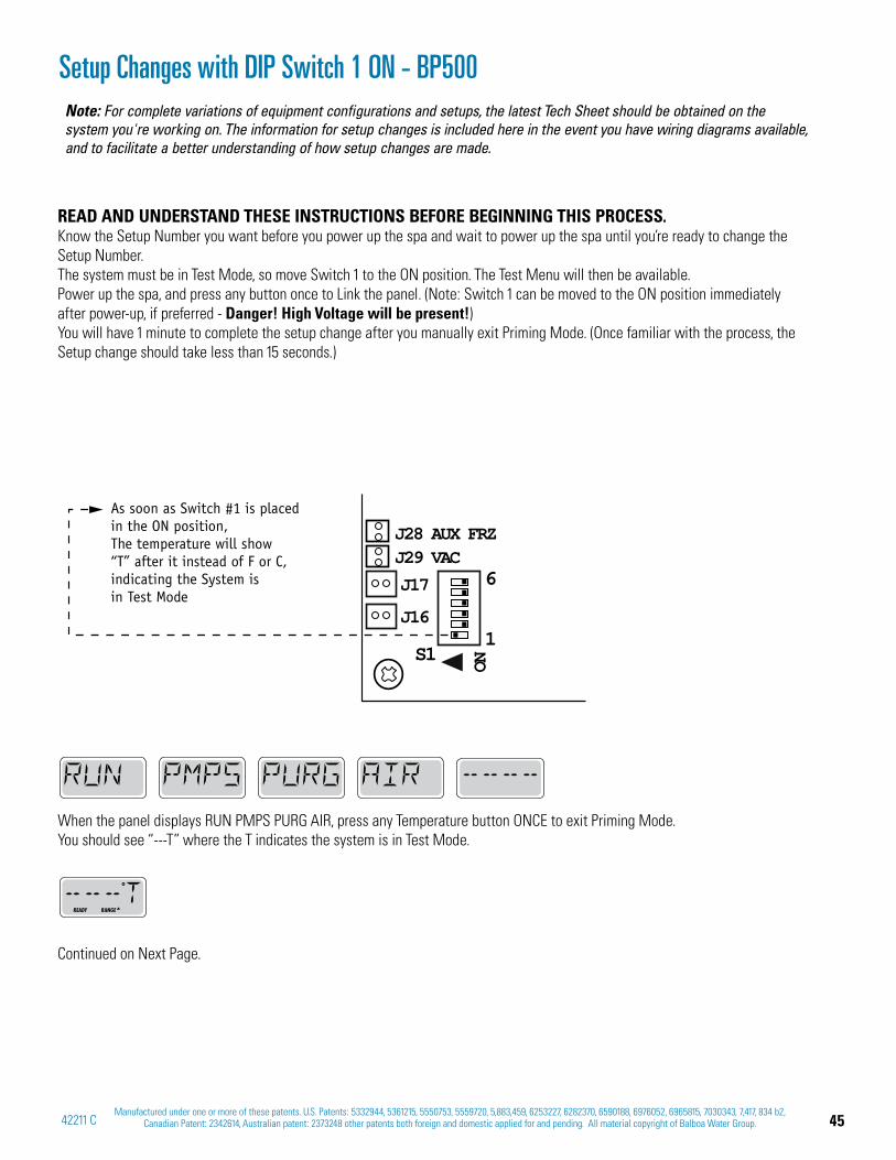
45Manufactured under one or more of these patents. U.S. Patents: 5332944, 5361215, 5550753, 5559720, 5,883,459, 6253227, 6282370, 6590188, 6976052, 6965815, 7030343, 7,417, 834 b2,
Canadian Patent: 2342614, Australian patent: 2373248 other patents both foreign and domestic applied for and pending. All material copyright of Balboa Water Group.42211 C
Setup Changes with DIP Switch 1 ON - BP500
As soon as Switch #1 is placed in the ON position,The temperature will show“T” after it instead of F or C, indicating the System isin Test Mode
1S1
6J17
J16
J29 VACJ28 AUX FRZ
ON
READ AND UNDERSTAND THESE INSTRUCTIONS BEFORE BEGINNING THIS PROCESS.Know the Setup Number you want before you power up the spa and wait to power up the spa until you’re ready to change the Setup Number. The system must be in Test Mode, so move Switch 1 to the ON position. The Test Menu will then be available.Power up the spa, and press any button once to Link the panel. (Note: Switch 1 can be moved to the ON position immediately after power-up, if preferred - Danger! High Voltage will be present!)You will have 1 minute to complete the setup change after you manually exit Priming Mode. (Once familiar with the process, the Setup change should take less than 15 seconds.)
When the panel displays RUN PMPS PURG AIR, press any Temperature button ONCE to exit Priming Mode. You should see “---T” where the T indicates the system is in Test Mode.
Continued on Next Page.
READY RANGE
Note: For complete variations of equipment configurations and setups, the latest Tech Sheet should be obtained on the system you're working on. The information for setup changes is included here in the event you have wiring diagrams available, and to facilitate a better understanding of how setup changes are made.
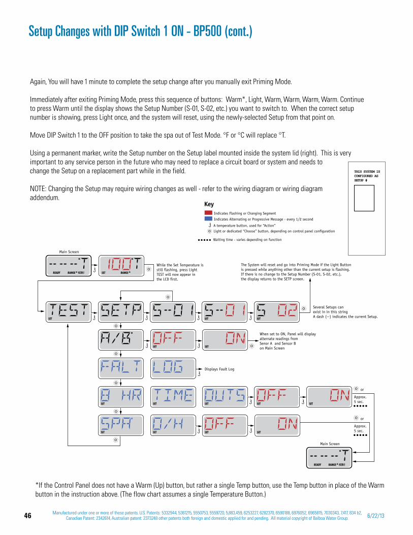
46 Manufactured under one or more of these patents. U.S. Patents: 5332944, 5361215, 5550753, 5559720, 5,883,459, 6253227, 6282370, 6590188, 6976052, 6965815, 7030343, 7,417, 834 b2, Canadian Patent: 2342614, Australian patent: 2373248 other patents both foreign and domestic applied for and pending. All material copyright of Balboa Water Group. 6/22/13
Setup Changes with DIP Switch 1 ON - BP500 (cont.)
Again, You will have 1 minute to complete the setup change after you manually exit Priming Mode.
Immediately after exiting Priming Mode, press this sequence of buttons: Warm*, Light, Warm, Warm, Warm, Warm. Continue to press Warm until the display shows the Setup Number (S-01, S-02, etc.) you want to switch to. When the correct setup number is showing, press Light once, and the system will reset, using the newly-selected Setup from that point on.
Move DIP Switch 1 to the OFF position to take the spa out of Test Mode. °F or °C will replace °T.
Using a permanent marker, write the Setup number on the Setup label mounted inside the system lid (right). This is very important to any service person in the future who may need to replace a circuit board or system and needs to change the Setup on a replacement part while in the field.
NOTE: Changing the Setup may require wiring changes as well - refer to the wiring diagram or wiring diagram addendum.
*If the Control Panel does not have a Warm (Up) button, but rather a single Temp button, use the Temp button in place of the Warm button in the instruction above. (The flow chart assumes a single Temperature Button.)
Indicates Flashing or Changing Segment
Key
A temperature button, used for “Action” Light or dedicated “Choose” button, depending on control panel configuration
Indicates Alternating or Progressive Message - every 1/2 second
Waiting time - varies depending on function
THIS SYSTEM ISCONFIGURED ASSETUP #
SETSET
The System will reset and go into Priming Mode if the Light Button is pressed while anything other than the current setup is flashing. If there is no change to the Setup Number (S-01, S-02, etc.), the display returns to the SETP screen.
Several Setups can exist in in this stringA dash (--) indicates the current Setup.SET
SET SET
SET SET
SET SET
While the Set Temperature is still flashing, press LightTEST will now appear in the LCD first.
SET RANGE
Main Screen
READY RANGE FLTR1
Main Screen
READY RANGE FLTR1
SET
Approx.5 sec.
or
Approx.5 sec.
or
SET
SET
SET
SET
When set to ON, Panel will display alternate readings from Senor A and Sensor B on Main Screen
Displays Fault Log
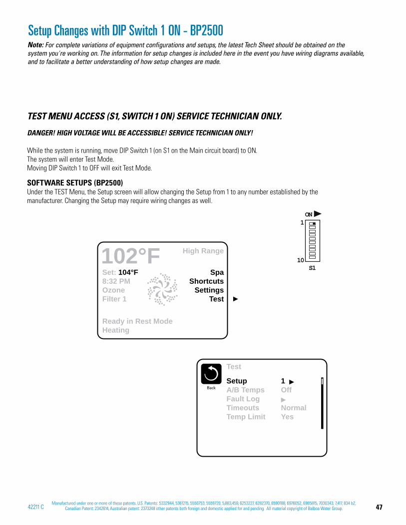
47Manufactured under one or more of these patents. U.S. Patents: 5332944, 5361215, 5550753, 5559720, 5,883,459, 6253227, 6282370, 6590188, 6976052, 6965815, 7030343, 7,417, 834 b2,
Canadian Patent: 2342614, Australian patent: 2373248 other patents both foreign and domestic applied for and pending. All material copyright of Balboa Water Group.42211 C
Setup Changes with DIP Switch 1 ON - BP2500
TEST MENU ACCESS (S1, SWITCH 1 ON) SERVICE TECHNICIAN ONLY.
DANGER! HIGH VOLTAGE WILL BE ACCESSIBLE! SERVICE TECHNICIAN ONLY!
While the system is running, move DIP Switch 1 (on S1 on the Main circuit board) to ON. The system will enter Test Mode. Moving DIP Switch 1 to OFF will exit Test Mode.
SOFTWARE SETUPS (BP2500) Under the TEST Menu, the Setup screen will allow changing the Setup from 1 to any number established by the manufacturer. Changing the Setup may require wiring changes as well.
Set: 104°F8:32 PMOzoneFilter 1
SpaShortcuts
SettingsTest
High Range102°F
Ready in Rest ModeHeating
ON1
10S1
Test
BackSetupA/B TempsFault LogTimeoutsTemp Limit
1Off
NormalYes
Note: For complete variations of equipment configurations and setups, the latest Tech Sheet should be obtained on the system you're working on. The information for setup changes is included here in the event you have wiring diagrams available, and to facilitate a better understanding of how setup changes are made.
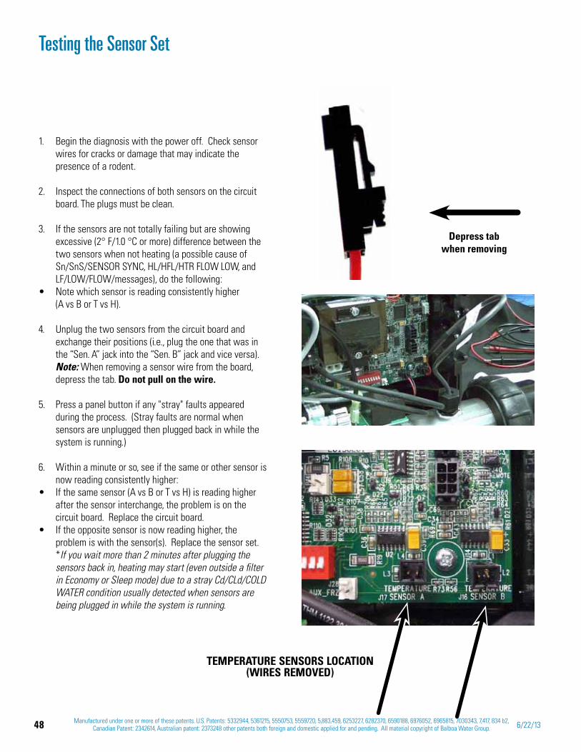
48 Manufactured under one or more of these patents. U.S. Patents: 5332944, 5361215, 5550753, 5559720, 5,883,459, 6253227, 6282370, 6590188, 6976052, 6965815, 7030343, 7,417, 834 b2, Canadian Patent: 2342614, Australian patent: 2373248 other patents both foreign and domestic applied for and pending. All material copyright of Balboa Water Group. 6/22/13
Begin the diagnosis with the power off. Check sensor 1. wires for cracks or damage that may indicate the presence of a rodent.
2. Inspect the connections of both sensors on the circuit board. The plugs must be clean.
3. If the sensors are not totally failing but are showing excessive (2° F/1.0 °C or more) difference between the two sensors when not heating (a possible cause of Sn/SnS/SENSOR SYNC, HL/HFL/HTR FLOW LOW, and LF/LOW/FLOW/messages), do the following:Note which sensor is reading consistently higher (A vs B or T vs H).
4. Unplug the two sensors from the circuit board and exchange their positions (i.e., plug the one that was in the “Sen. A” jack into the “Sen. B” jack and vice versa). Note: When removing a sensor wire from the board, depress the tab. Do not pull on the wire.
5. Press a panel button if any "stray" faults appeared during the process. (Stray faults are normal when sensors are unplugged then plugged back in while the system is running.)
6. Within a minute or so, see if the same or other sensor is now reading consistently higher:If the same sensor (A vs B or T vs H) is reading higher after the sensor interchange, the problem is on the circuit board. Replace the circuit board.If the opposite sensor is now reading higher, the problem is with the sensor(s). Replace the sensor set.
*If you wait more than 2 minutes after plugging the sensors back in, heating may start (even outside a filter in Economy or Sleep mode) due to a stray Cd/CLd/COLD WATER condition usually detected when sensors are being plugged in while the system is running.
Testing the Sensor Set
Depress tab when removing
TEMPERATURE SENSORS LOCATION (WIRES REMOVED)
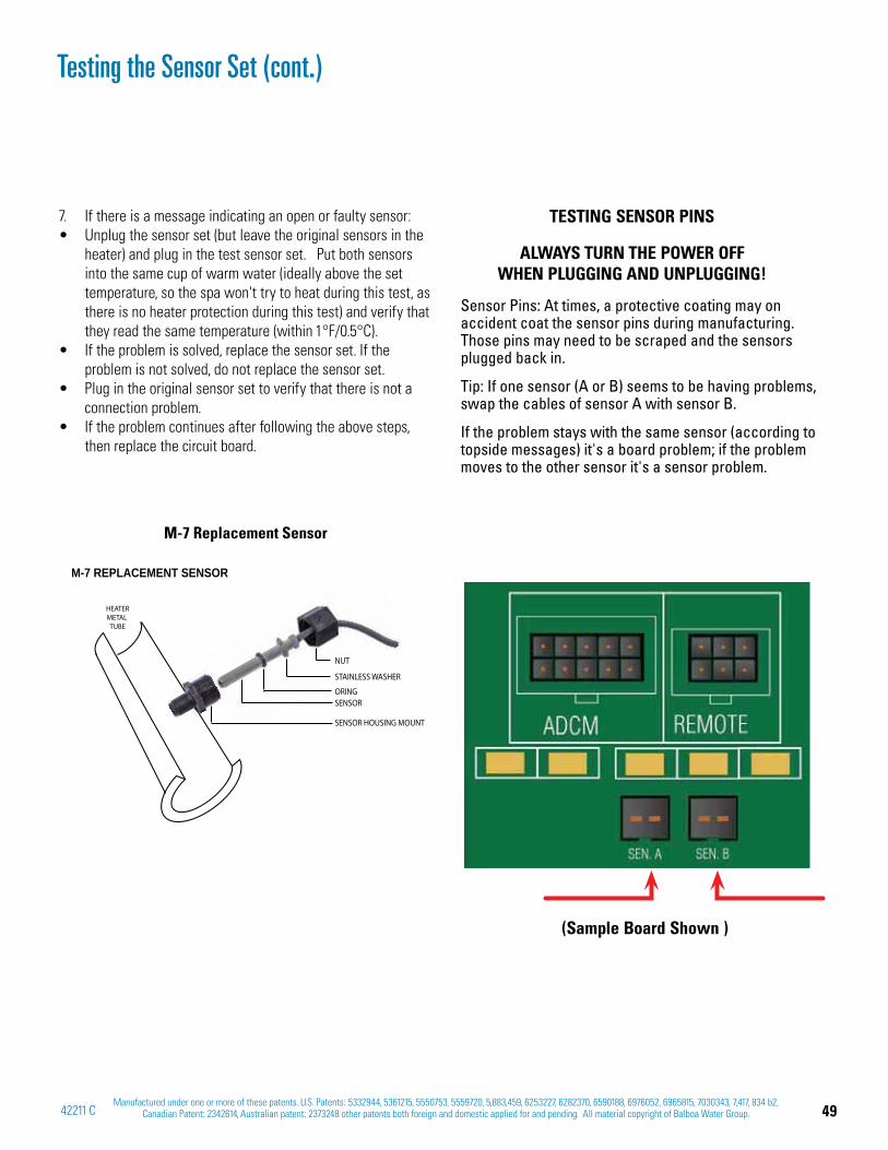
49Manufactured under one or more of these patents. U.S. Patents: 5332944, 5361215, 5550753, 5559720, 5,883,459, 6253227, 6282370, 6590188, 6976052, 6965815, 7030343, 7,417, 834 b2,
Canadian Patent: 2342614, Australian patent: 2373248 other patents both foreign and domestic applied for and pending. All material copyright of Balboa Water Group.42211 C
7. If there is a message indicating an open or faulty sensor:Unplug the sensor set (but leave the original sensors in the heater) and plug in the test sensor set. Put both sensors into the same cup of warm water (ideally above the set temperature, so the spa won't try to heat during this test, as there is no heater protection during this test) and verify that they read the same temperature (within 1°F/0.5°C).If the problem is solved, replace the sensor set. If the problem is not solved, do not replace the sensor set.Plug in the original sensor set to verify that there is not a connection problem.If the problem continues after following the above steps, then replace the circuit board.
Sensor Pins: At times, a protective coating may on accident coat the sensor pins during manufacturing. Those pins may need to be scraped and the sensors plugged back in.
Tip: If one sensor (A or B) seems to be having problems, swap the cables of sensor A with sensor B.
If the problem stays with the same sensor (according to topside messages) it's a board problem; if the problem moves to the other sensor it's a sensor problem.
TESTING SENSOR PINS
ALWAYS TURN THE POWER OFF WHEN PLUGGING AND UNPLUGGING!
Testing the Sensor Set (cont.)
M-7 REPLACEMENT SENSOR
NUT
STAINLESS WASHER
ORINGSENSOR
SENSOR HOUSING MOUNT
HEATERMETAL
TUBE
M-7 Replacement Sensor
(Sample Board Shown )
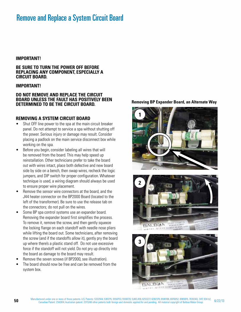
50 Manufactured under one or more of these patents. U.S. Patents: 5332944, 5361215, 5550753, 5559720, 5,883,459, 6253227, 6282370, 6590188, 6976052, 6965815, 7030343, 7,417, 834 b2, Canadian Patent: 2342614, Australian patent: 2373248 other patents both foreign and domestic applied for and pending. All material copyright of Balboa Water Group. 6/22/13
Remove and Replace a System Circuit Board
Removing BP Expander Board, an Alternate Way
IMPORTANT!
BE SURE TO TURN THE POWER OFF BEFORE REPLACING ANY COMPONENT, ESPECIALLY A CIRCUIT BOARD.
IMPORTANT!
DO NOT REMOVE AND REPLACE THE CIRCUIT BOARD UNLESS THE FAULT HAS POSITIVELY BEEN DETERMINED TO BE THE CIRCUIT BOARD.
REMOVING A SYSTEM CIRCUIT BOARDShut OFF line power to the spa at the main circuit breaker panel. Do not attempt to service a spa without shutting off the power. Serious injury or damage may result. Consider placing a padlock on the main service disconnect box while working on the spa. Before you begin, consider labeling all wires that will be removed from the board. This may help speed up reinstallation. Other technicians prefer to take the board out with wires intact, place both defective and new board side by side on a bench, then swap wires, recheck the logic jumpers, and DIP switch for proper configuration. Whatever technique is used, a wiring diagram should always be used to ensure proper wire placement.Remove the sensor wire connectors at the board, and the J44 heater connector on the BP2000 Board (located to the left of the transformer). Be sure to use the release tab on the connectors; do not pull on the wires. Some BP spa control systems use an expander board. Removing the expander board first simplifies the process. To remove it, remove the screw, and then gently squeeze the locking flange on each standoff with needle nose pliers while lifting the board out. Some technicians, after removing the screw (and if the standoffs allow it), gently pry the board up where there’s a plastic stand off. Do not use excessive force if the standoff will not yield. Do not pry up directly into the board as damage to the board may result.Remove the seven screws (if BP2000, see illustration). The board should now be free and can be removed from the system box.
1
2
3

51Manufactured under one or more of these patents. U.S. Patents: 5332944, 5361215, 5550753, 5559720, 5,883,459, 6253227, 6282370, 6590188, 6976052, 6965815, 7030343, 7,417, 834 b2,
Canadian Patent: 2342614, Australian patent: 2373248 other patents both foreign and domestic applied for and pending. All material copyright of Balboa Water Group.42211 C
Remove and Replace a System Circuit Board (cont.)
BP2100 board without wires
BP2100 board screw locations
F4 3A SLO-BLOW
J25 J31
J26 J30
115V 115V
230V
F3 0.3A SLO-BLOW
J25=HTR1J26=HTR2J27=HTR3J30=TESTJ31=CE HTR SEL
F7 10A 250VAC
F2 10A 250VAC
J44
3
TB1
J15
ON
10
S1
K5
K1
K3
T1
K2
K4
K8
LIGHT
GND
J33J21 J32J9
1
2
3
4
2
K6
4
3
2
1
J45
J110
J79
J54
J72
J42
J3
J37
J4 J1J61
J47
J77
J75
J78
J36
J60
J46J38
J39
J111
J53 J58
J11
J41
J48
J6
J7
J49
J19
J50
J13
J12
J88
J62
F6 30AF8 30A
J56
J57
J55
J59
J51
J52
J98
J10
J81 J20
J18
J43
CIRC
PUM
P
OZON
E
A/V
HOT
PUMP
1
J14K9
J5AUX
J8AUX
J40
REMOTE
J35MAIN
J34MAIN
J109
J27
J91
J22J23
SERIAL
J29VAC
J28AUXFRZ
J17 J16
24082_D
J101
J108J24
J107
K12
K7
INSTALLING A SYSTEM CIRCUIT BOARDWhen reinstalling the board:
Torque main board hold down screws to 8-10 in/lbs. Do not over tighten as damage to the board may result. Reconnect all wires and slip-on connectors. Restore power to the spa at the main breaker.Test to make sure all functions work correctly.
COMPATIBILITY ON DUAL BOARD CONTROL SYSTEMSSystem BP600 has two boards: a power board and logic board. If one board is found to be defective and is replaced with a newer revision board, it will still be compatible with the other, older system board.
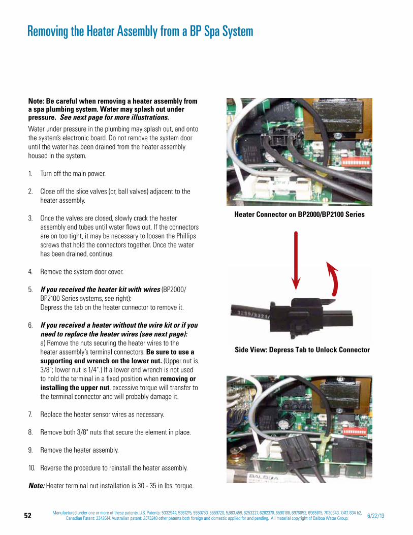
52 Manufactured under one or more of these patents. U.S. Patents: 5332944, 5361215, 5550753, 5559720, 5,883,459, 6253227, 6282370, 6590188, 6976052, 6965815, 7030343, 7,417, 834 b2, Canadian Patent: 2342614, Australian patent: 2373248 other patents both foreign and domestic applied for and pending. All material copyright of Balboa Water Group. 6/22/13
Removing the Heater Assembly from a BP Spa System
Note: Be careful when removing a heater assembly from a spa plumbing system. Water may splash out under pressure. See next page for more illustrations.
Water under pressure in the plumbing may splash out, and onto the system’s electronic board. Do not remove the system door until the water has been drained from the heater assembly housed in the system.
Turn off the main power. 1.
Close off the 2. slice valves (or, ball valves) adjacent to the heater assembly.
Once the valves are closed, slowly crack the heater 3. assembly end tubes until water flows out. If the connectors are on too tight, it may be necessary to loosen the Phillips screws that hold the connectors together. Once the water has been drained, continue.
Remove the system door cover. 4.
If you received the 5. heater kit with wires (BP2000/BP2100 Series systems, see right): Depress the tab on the heater connector to remove it.
If you received a heater without the wire kit or if you 6. need to replace the heater wires (see next page): a) Remove the nuts securing the heater wires to the heater assembly’s terminal connectors. Be sure to use a supporting end wrench on the lower nut. (Upper nut is 3/8"; lower nut is 1/4".) If a lower end wrench is not used to hold the terminal in a fixed position when removing or installing the upper nut, excessive torque will transfer to the terminal connector and will probably damage it.
Replace the 7. heater sensor wires as necessary.
Remove both 3/8" nuts that secure the element in place. 8.
Remove the heater assembly. 9.
Reverse the procedure to reinstall the heater assembly. 10.
Note: Heater terminal nut installation is 30 - 35 in lbs. torque.
Heater Connector on BP2000/BP2100 Series
Side View: Depress Tab to Unlock Connector
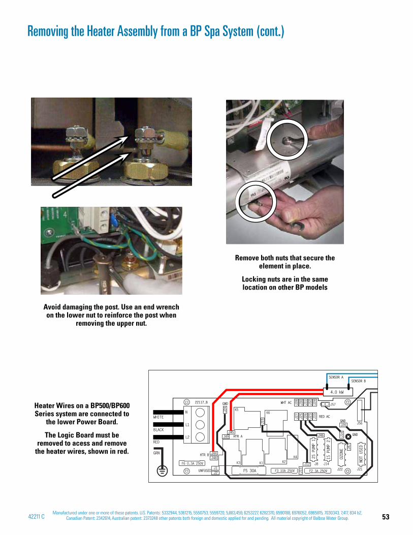
53Manufactured under one or more of these patents. U.S. Patents: 5332944, 5361215, 5550753, 5559720, 5,883,459, 6253227, 6282370, 6590188, 6976052, 6965815, 7030343, 7,417, 834 b2,
Canadian Patent: 2342614, Australian patent: 2373248 other patents both foreign and domestic applied for and pending. All material copyright of Balboa Water Group.42211 C
Removing the Heater Assembly from a BP Spa System (cont.)
Remove both nuts that secure the element in place.
Locking nuts are in the same location on other BP models
Avoid damaging the post. Use an end wrench on the lower nut to reinforce the post when
removing the upper nut.
Heater Wires on a BP500/BP600 Series system are connected to
the lower Power Board.
The Logic Board must be removed to acess and remove
the heater wires, shown in red.
L2
L1
N
F3 10A 250V F2 3A 250V
F6 0.3A 250V
J44J48
J1J2
J24
J45J49
J15
J16
J47
J13
J27
J25
J26
J23
J33
J28
J30
J31
J32
J29
J12
J46
J20
J57
J8 J14J22 J21
J56
F5 30A
GND
K3
K5K6
K2K1
K4 OZONE
22117_B
RED AC
GND
GND
WHT AC
HTR A
HTR B
UNFUSED
SENSOR ASENSOR B
NOT USED
2S PUMP 1
1S PUMP 2
WHITE
BLACK
RED
GRN
4.0 kW
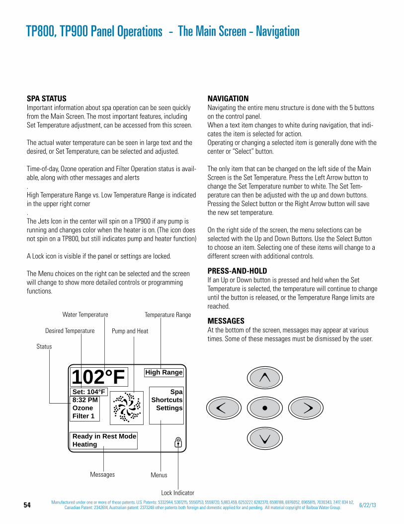
54 Manufactured under one or more of these patents. U.S. Patents: 5332944, 5361215, 5550753, 5559720, 5,883,459, 6253227, 6282370, 6590188, 6976052, 6965815, 7030343, 7,417, 834 b2, Canadian Patent: 2342614, Australian patent: 2373248 other patents both foreign and domestic applied for and pending. All material copyright of Balboa Water Group. 6/22/13
SPA STATUS Important information about spa operation can be seen quickly from the Main Screen. The most important features, including Set Temperature adjustment, can be accessed from this screen.
The actual water temperature can be seen in large text and the desired, or Set Temperature, can be selected and adjusted. Time-of-day, Ozone operation and Filter Operation status is avail-able, along with other messages and alerts.High Temperature Range vs. Low Temperature Range is indicated in the upper right corner.The Jets Icon in the center will spin on a TP900 if any pump is running and changes color when the heater is on. (The icon does not spin on a TP800, but still indicates pump and heater function)
A Lock icon is visible if the panel or settings are locked.
The Menu choices on the right can be selected and the screen will change to show more detailed controls or programming functions.
Set: 104°F8:32 PMOzoneFilter 1
SpaShortcuts
Settings
High Range102°F
Ready in Rest ModeHeating
Water Temperature
Messages
Desired Temperature
Temperature Range
Pump and Heat
Menus
Lock Indicator
Status
NAVIGATION Navigating the entire menu structure is done with the 5 buttons on the control panel.When a text item changes to white during navigation, that indi-cates the item is selected for action.Operating or changing a selected item is generally done with the center or “Select” button.
The only item that can be changed on the left side of the Main Screen is the Set Temperature. Press the Left Arrow button to change the Set Temperature number to white. The Set Tem-perature can then be adjusted with the up and down buttons. Pressing the Select button or the Right Arrow button will save the new set temperature.
On the right side of the screen, the menu selections can be selected with the Up and Down Buttons. Use the Select Button to choose an item. Selecting one of these items will change to a different screen with additional controls.
PRESS-AND-HOLDIf an Up or Down button is pressed and held when the Set Temperature is selected, the temperature will continue to change until the button is released, or the Temperature Range limits are reached.
MESSAGESAt the bottom of the screen, messages may appear at various times. Some of these messages must be dismissed by the user.
The Main Screen - NavigationTP800, TP900 Panel Operations -

55Manufactured under one or more of these patents. U.S. Patents: 5332944, 5361215, 5550753, 5559720, 5,883,459, 6253227, 6282370, 6590188, 6976052, 6965815, 7030343, 7,417, 834 b2,
Canadian Patent: 2342614, Australian patent: 2373248 other patents both foreign and domestic applied for and pending. All material copyright of Balboa Water Group.42211 C
TP800, TP900 Priming Mode Start-up Sequence
PREPARATION AND FILLINGFill the spa to its correct operating level. Be sure to open all valves and jets in the plumbing system before filling to allow as much air as possible to escape from the plumbing and the control system during the filling process.After turning the power on at the main power panel, the top-side panel will display a splash, or startup screen.
PRIMING MODE – After the initial start-up sequence, the control will enter Priming Mode and display a Priming Mode screen. Only pump icons ap-pear on the priming mode screen. The system will automatically return to normal heating and filtering at the end of the priming mode, which lasts 4-5 minutes.
During the priming mode, the heater is disabled to allow the priming process to be completed without the possibility of ener-gizing the heater under low-flow or no-flow conditions. Nothing comes on automatically, but the pump(s) can be energized by selecting the “Jet” buttons.
If the spa has a Circ Pump, it can be turned on and off by press-ing the “Circ Pump” button during Priming Mode. In addition, if the spa has a Circ Pump, it can be activated by pressing the dedi-cated “Light” button during Priming Mode when using a TP800.
Manually exit Priming Mode by pressing the “Exit” Button.
PRIMING THE PUMPSAs soon as the Priming Mode screen appears on the panel, select the “Jets 1” button once to start Pump 1 in low-speed and then again to switch to high-speed. Also, select the other pumps, to turn them on. The pumps should be running in high-speed to facilitate priming. If the pumps have not primed after 2 minutes, and water is not flowing from the jets in the spa, do not allow the pumps to continue to run. Turn off the pumps and repeat the process.
Note: Turning the power off and back on again will initiate a new pump priming session. Sometimes momentarily turning the pump off and on will help it to prime. Do not do this more than 5 times. If the pump(s) will not prime, shut off the power to the spa.
Important: A pump should not be allowed to run without prim-ing for more than 2 minutes. Under NO circumstances should a pump be allowed to run without priming beyond the end of the 4-5 minute priming mode. Doing so may cause damage to the pump and cause the system to energize the heater and go into an overheat condition.
EXITING PRIMING MODEYou can manually exit Priming Mode by navigating to the “Back” button on the Priming Mode Screen. Note that if you do not manually exit the priming mode as described above, the priming mode will be automatically terminated after 4-5 minutes. Be sure that the pump(s) have been primed by this time. Once the system has exited Priming Mode, the top-side panel will display the Main Screen, but the display will not show the temperature yet, as shown below. This is because the system requires approximately 1 minute of water flowing through the heater to determine the water temperature and display it.
M0[XX] numbers are Message Codes.
A message with an asterisk [*] can be reset from the topside panel.
– – –°F – – –°C
Jets 1 Jets 2 Jets 3 Circ
Priming Mode
Back
56 Manufactured under one or more of these patents. U.S. Patents: 5332944, 5361215, 5550753, 5559720, 5,883,459, 6253227, 6282370, 6590188, 6976052, 6965815, 7030343, 7,417, 834 b2, Canadian Patent: 2342614, Australian patent: 2373248 other patents both foreign and domestic applied for and pending. All material copyright of Balboa Water Group. 6/22/13
BE SURE TO SET THE TIME-OF-DAYSetting the time-of-day is important for determining filtration times and other background features. “Set Time” will appear on the display if no time-of-day is set in the memory.
On the Settings Screen, select the Time-of-Day line. On the Time-of-Day screen, simply navigate right and left to select the Hour, Minutes, AM/PM and 12/24 Hour segments. Use the Up and Down Buttons to make changes.
SAVING SETTINGSThe Time-of-Day screen is a simple, editable screen that illus-trates a feature of the control that applies to all other editable screens as well.
When changes are made, the icon to go “Back” changes to “Save” and a new icon for “Cancel” appears under the Save icon. Navigating to the left will highlight the Save icon, and navigat-ing down from there will allow the user to cancel the pending change. Pressing the “Select” button will save or cancel the changes and go back to the previous screen.NOTE: If power is interrupted to the system, Time-of-Day will be maintained for several days.
PUMPSOn the Spa Screen, select a “Jets” button once to turn the pump on or off, and to shift between low- and high-speeds if equipped. If left running, the pump will turn off after a time-out period. The pump 1 low-speed will time out after 30 minutes. The high-speed will time-out after 15 minutes.
On non-circ systems, the low-speed of pump 1 runs when the blower or any other pump is on. If the spa is in Ready Mode, Pump 1 low may also activate for at least 1 minute every 30 minutes to detect the spa temperature (polling) and then to heat to the set temperature if needed. When the low-speed turns on automatically, it cannot be deactivated from the panel, however the high speed may be started.
CIRCULATION PUMP MODESSome spas may be manufactured with Circ Pump settings that allow programming filtration cycle duration. Some circ Modes are pre-programmed to operate 24 hours a day and are not programmable.
TP800, TP900 Spa Behavior
If your system is equipped with a circ pump, it may be configured to work in one of three different ways:
The circ pump operates continuously (24 hours) with the 1. exception of turning off for 30 minutes at a time when the water temperature reaches 3°F (1.5°C) above the set tem-perature (most likely to happen in very hot climates).The circ pump stays on continuously, regardless of water 2. temperature.A 3. programmable circ pump will come on when the system is checking temperature (polling), during filter cycles, during freeze conditions, or when another pump is on.The specific Circulation Mode that is used has been deter-mined by the Manufacturer and cannot be changed in the field. Other device options may be available, like Blower, Light, Mist, etc.
FILTRATION AND OZONEOn non-circ systems, Pump 1 low and the ozone generator will run during filtration. On circ systems, the ozone will generally run with the circ pump, but can be limited to filtration cycles.The system is factory-programmed with one filter cycle that will run in the evening (assuming the time-of-day is properly set) when energy rates are often lower. The filter time and duration are programmable.
A second filter cycle can be enabled as needed.At the start of each filter cycle, the water devices like blower, mist device (if these exist) and other pumps will run briefly to purge the plumbing to maintain good water quality.
FREEZE PROTECTIONIf the temperature sensors within the heater detect a low enough temperature, then the water devices automatically activate to provide freeze protection. The water devices will run either continuously or periodically depending on conditions.
In colder climates, an optional additional freeze sensor may be added to protect against freeze conditions that may not be sensed by the standard sensors. Auxiliary freeze sensor pro-tection acts similarly except with the temperature thresholds determined by the switch. See your dealer for details.
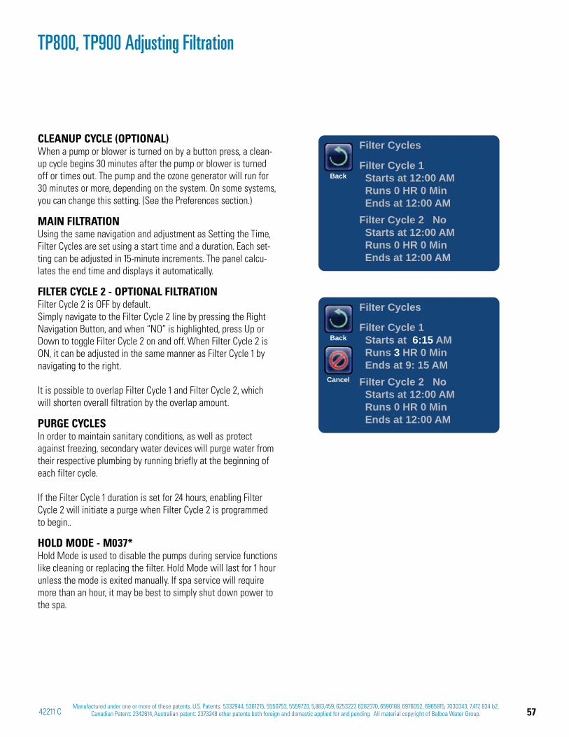
57Manufactured under one or more of these patents. U.S. Patents: 5332944, 5361215, 5550753, 5559720, 5,883,459, 6253227, 6282370, 6590188, 6976052, 6965815, 7030343, 7,417, 834 b2,
Canadian Patent: 2342614, Australian patent: 2373248 other patents both foreign and domestic applied for and pending. All material copyright of Balboa Water Group.42211 C
CLEANUP CYCLE (OPTIONAL)When a pump or blower is turned on by a button press, a clean-up cycle begins 30 minutes after the pump or blower is turned off or times out. The pump and the ozone generator will run for 30 minutes or more, depending on the system. On some systems, you can change this setting. (See the Preferences section.)
MAIN FILTRATIONUsing the same navigation and adjustment as Setting the Time, Filter Cycles are set using a start time and a duration. Each set-ting can be adjusted in 15-minute increments. The panel calcu-lates the end time and displays it automatically.
FILTER CYCLE 2 - OPTIONAL FILTRATIONFilter Cycle 2 is OFF by default. Simply navigate to the Filter Cycle 2 line by pressing the Right Navigation Button, and when “NO” is highlighted, press Up or Down to toggle Filter Cycle 2 on and off. When Filter Cycle 2 is ON, it can be adjusted in the same manner as Filter Cycle 1 by navigating to the right.
It is possible to overlap Filter Cycle 1 and Filter Cycle 2, which will shorten overall filtration by the overlap amount.
PURGE CYCLESIn order to maintain sanitary conditions, as well as protect against freezing, secondary water devices will purge water from their respective plumbing by running briefly at the beginning of each filter cycle.
If the Filter Cycle 1 duration is set for 24 hours, enabling Filter Cycle 2 will initiate a purge when Filter Cycle 2 is programmed to begin..
HOLD MODE - M037*Hold Mode is used to disable the pumps during service functions like cleaning or replacing the filter. Hold Mode will last for 1 hour unless the mode is exited manually. If spa service will require more than an hour, it may be best to simply shut down power to the spa.
TP800, TP900 Adjusting Filtration
Filter Cycles
Filter Cycle 1 Starts at 12:00 AM Runs 0 HR 0 Min Ends at 12:00 AMFilter Cycle 2 No Starts at 12:00 AM Runs 0 HR 0 Min Ends at 12:00 AM
Back
Filter Cycles
Filter Cycle 1 Starts at 6:15 AM Runs 3 HR 0 Min Ends at 9: 15 AMFilter Cycle 2 No Starts at 12:00 AM Runs 0 HR 0 Min Ends at 12:00 AM
Back
Cancel
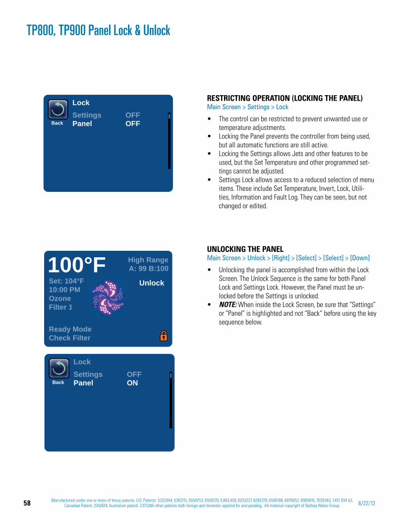
58 Manufactured under one or more of these patents. U.S. Patents: 5332944, 5361215, 5550753, 5559720, 5,883,459, 6253227, 6282370, 6590188, 6976052, 6965815, 7030343, 7,417, 834 b2, Canadian Patent: 2342614, Australian patent: 2373248 other patents both foreign and domestic applied for and pending. All material copyright of Balboa Water Group. 6/22/13
BackSettings OFFPanel OFF
Lock RESTRICTING OPERATION (LOCKING THE PANEL)Main Screen > Settings > Lock
The control can be restricted to prevent unwanted use or temperature adjustments.Locking the Panel prevents the controller from being used, but all automatic functions are still active. Locking the Settings allows Jets and other features to be used, but the Set Temperature and other programmed set-tings cannot be adjusted. Settings Lock allows access to a reduced selection of menu items. These include Set Temperature, Invert, Lock, Utili-ties, Information and Fault Log. They can be seen, but not changed or edited.
Set: 104°F10:00 PMOzoneFilter 1
High RangeA: 99 B:100100°F
Unlock
Ready ModeCheck Filter
BackSettings OFFPanel ON
Lock
UNLOCKING THE PANELMain Screen > Unlock > [Right] > [Select] > [Select] > [Down]
Unlocking the panel is accomplished from within the Lock Screen. The Unlock Sequence is the same for both Panel Lock and Settings Lock. However, the Panel must be un-locked before the Settings is unlocked. NOTE: When inside the Lock Screen, be sure that “Settings” or “Panel” is highlighted and not “Back” before using the key sequence below.
TP800, TP900 Panel Lock & Unlock
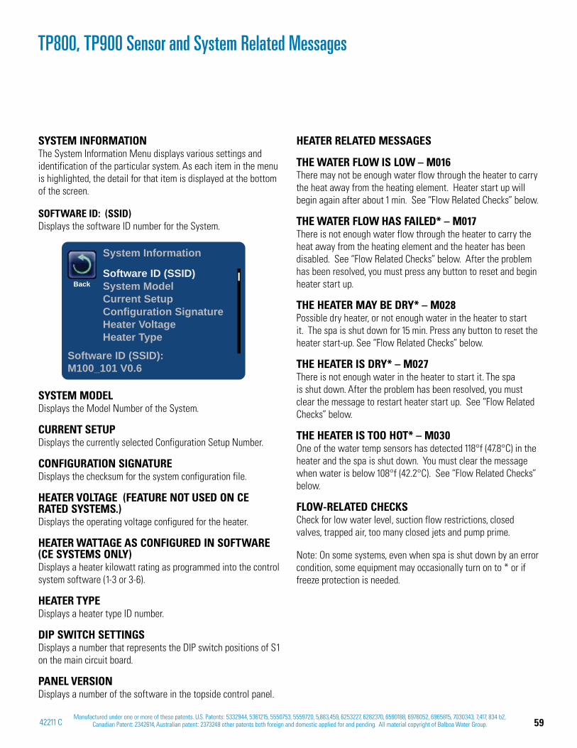
59Manufactured under one or more of these patents. U.S. Patents: 5332944, 5361215, 5550753, 5559720, 5,883,459, 6253227, 6282370, 6590188, 6976052, 6965815, 7030343, 7,417, 834 b2,
Canadian Patent: 2342614, Australian patent: 2373248 other patents both foreign and domestic applied for and pending. All material copyright of Balboa Water Group.42211 C
SYSTEM INFORMATION The System Information Menu displays various settings and identification of the particular system. As each item in the menu is highlighted, the detail for that item is displayed at the bottom of the screen.
SOFTWARE ID: (SSID) Displays the software ID number for the System.
SYSTEM MODEL Displays the Model Number of the System.
CURRENT SETUPDisplays the currently selected Configuration Setup Number.
CONFIGURATION SIGNATURE Displays the checksum for the system configuration file.
HEATER VOLTAGE (FEATURE NOT USED ON CERATED SYSTEMS.) Displays the operating voltage configured for the heater.
HEATER WATTAGE AS CONFIGURED IN SOFTWARE (CE SYSTEMS ONLY)Displays a heater kilowatt rating as programmed into the control system software (1-3 or 3-6).
HEATER TYPE Displays a heater type ID number.
DIP SWITCH SETTINGS Displays a number that represents the DIP switch positions of S1 on the main circuit board.
PANEL VERSION Displays a number of the software in the topside control panel.
HEATER RELATED MESSAGES
THE WATER FLOW IS LOW – M016There may not be enough water flow through the heater to carry the heat away from the heating element. Heater start up will begin again after about 1 min. See “Flow Related Checks” below.
THE WATER FLOW HAS FAILED* – M017There is not enough water flow through the heater to carry the heat away from the heating element and the heater has been disabled. See “Flow Related Checks” below. After the problem has been resolved, you must press any button to reset and begin heater start up.
THE HEATER MAY BE DRY* – M028Possible dry heater, or not enough water in the heater to start it. The spa is shut down for 15 min. Press any button to reset the heater start-up. See “Flow Related Checks” below.
THE HEATER IS DRY* – M027There is not enough water in the heater to start it. The spa is shut down. After the problem has been resolved, you must clear the message to restart heater start up. See “Flow Related Checks” below.
THE HEATER IS TOO HOT* – M030One of the water temp sensors has detected 118°f (47.8°C) in the heater and the spa is shut down. You must clear the message when water is below 108°f (42.2°C). See “Flow Related Checks” below.
FLOW-RELATED CHECKSCheck for low water level, suction flow restrictions, closed valves, trapped air, too many closed jets and pump prime.
Note: On some systems, even when spa is shut down by an error condition, some equipment may occasionally turn on to * or if freeze protection is needed.
TP800, TP900 Sensor and System Related Messages
Back
System Information
Software ID (SSID)System ModelCurrent SetupConfiguration SignatureHeater VoltageHeater Type
Software ID (SSID):M100_101 V0.6
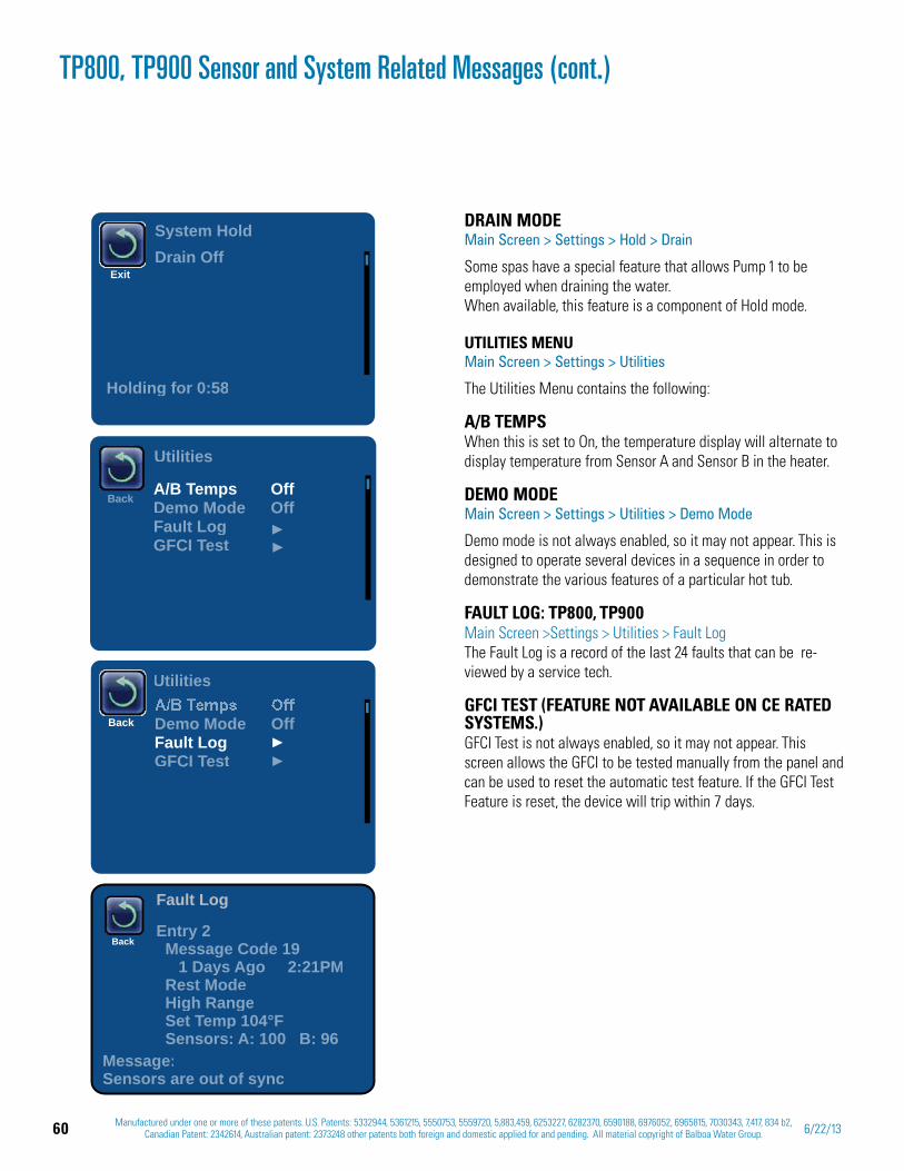
60 Manufactured under one or more of these patents. U.S. Patents: 5332944, 5361215, 5550753, 5559720, 5,883,459, 6253227, 6282370, 6590188, 6976052, 6965815, 7030343, 7,417, 834 b2, Canadian Patent: 2342614, Australian patent: 2373248 other patents both foreign and domestic applied for and pending. All material copyright of Balboa Water Group. 6/22/13
TP800, TP900 Sensor and System Related Messages (cont.)
DRAIN MODEMain Screen > Settings > Hold > Drain
Some spas have a special feature that allows Pump 1 to be employed when draining the water. When available, this feature is a component of Hold mode.
UTILITIES MENU Main Screen > Settings > Utilities
The Utilities Menu contains the following:
A/B TEMPS When this is set to On, the temperature display will alternate to display temperature from Sensor A and Sensor B in the heater.
DEMO MODE Main Screen > Settings > Utilities > Demo Mode
Demo mode is not always enabled, so it may not appear. This is designed to operate several devices in a sequence in order to demonstrate the various features of a particular hot tub.
FAULT LOG: TP800, TP900Main Screen >Settings > Utilities > Fault LogThe Fault Log is a record of the last 24 faults that can be re-viewed by a service tech.
GFCI TEST (FEATURE NOT AVAILABLE ON CE RATED SYSTEMS.) GFCI Test is not always enabled, so it may not appear. This screen allows the GFCI to be tested manually from the panel and can be used to reset the automatic test feature. If the GFCI Test Feature is reset, the device will trip within 7 days.
ExitDrain Off
Holding for 0:58
System Hold
Back
Utilities
A/B Temps OffDemo Mode OffFault LogGFCI Test
Fault Log
Entry 2 Message Code 19 1 Days Ago 2:21PM Rest ModeHigh Range
Set Temp 104°F Sensors: A: 100 B: 96
Message:Sensors are out of sync
Back
Back Demo Mode OffFault LogGFCI Test
Utilities
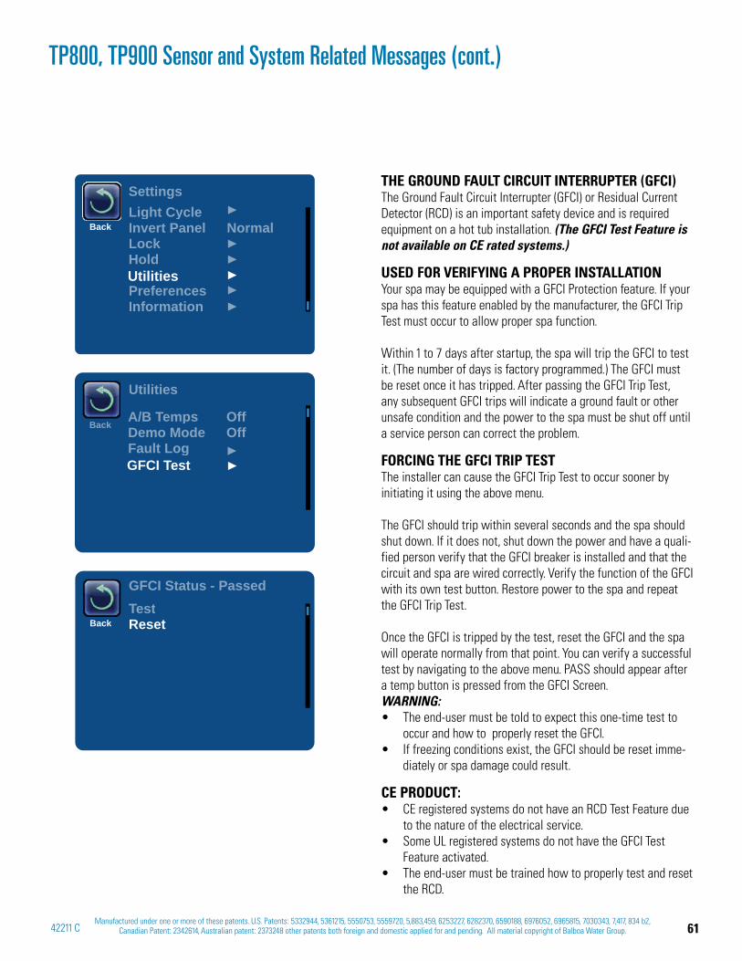
61Manufactured under one or more of these patents. U.S. Patents: 5332944, 5361215, 5550753, 5559720, 5,883,459, 6253227, 6282370, 6590188, 6976052, 6965815, 7030343, 7,417, 834 b2,
Canadian Patent: 2342614, Australian patent: 2373248 other patents both foreign and domestic applied for and pending. All material copyright of Balboa Water Group.42211 C
Settings
BackLight CycleInvert Panel NormalLockHold
PreferencesInformation
Utilities
Back
Utilities
A/B Temps OffDemo Mode OffFault LogGFCI Test
BackTestReset
GFCI Status - Passed
THE GROUND FAULT CIRCUIT INTERRUPTER (GFCI)The Ground Fault Circuit Interrupter (GFCI) or Residual Current Detector (RCD) is an important safety device and is required equipment on a hot tub installation. (The GFCI Test Feature is not available on CE rated systems.)
USED FOR VERIFYING A PROPER INSTALLATIONYour spa may be equipped with a GFCI Protection feature. If your spa has this feature enabled by the manufacturer, the GFCI Trip Test must occur to allow proper spa function.
Within 1 to 7 days after startup, the spa will trip the GFCI to test it. (The number of days is factory programmed.) The GFCI must be reset once it has tripped. After passing the GFCI Trip Test, any subsequent GFCI trips will indicate a ground fault or other unsafe condition and the power to the spa must be shut off until a service person can correct the problem.
FORCING THE GFCI TRIP TESTThe installer can cause the GFCI Trip Test to occur sooner by initiating it using the above menu.
The GFCI should trip within several seconds and the spa should shut down. If it does not, shut down the power and have a quali-fied person verify that the GFCI breaker is installed and that the circuit and spa are wired correctly. Verify the function of the GFCI with its own test button. Restore power to the spa and repeat the GFCI Trip Test.
Once the GFCI is tripped by the test, reset the GFCI and the spa will operate normally from that point. You can verify a successful test by navigating to the above menu. PASS should appear after a temp button is pressed from the GFCI Screen. WARNING:
The end-user must be told to expect this one-time test to occur and how to properly reset the GFCI.If freezing conditions exist, the GFCI should be reset imme-diately or spa damage could result.
CE PRODUCT:CE registered systems do not have an RCD Test Feature due to the nature of the electrical service. Some UL registered systems do not have the GFCI Test Feature activated.The end-user must be trained how to properly test and reset the RCD.
TP800, TP900 Sensor and System Related Messages (cont.)
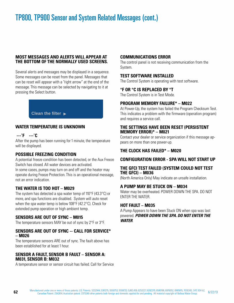
62 Manufactured under one or more of these patents. U.S. Patents: 5332944, 5361215, 5550753, 5559720, 5,883,459, 6253227, 6282370, 6590188, 6976052, 6965815, 7030343, 7,417, 834 b2, Canadian Patent: 2342614, Australian patent: 2373248 other patents both foreign and domestic applied for and pending. All material copyright of Balboa Water Group. 6/22/13
MOST MESSAGES AND ALERTS WILL APPEAR AT THE BOTTOM OF THE NORMALLY USED SCREENS.
Several alerts and messages may be displayed in a sequence. Some messages can be reset from the panel. Messages that can be reset will appear with a “right arrow” at the end of the message. This message can be selected by navigating to it at pressing the Select button.
WATER TEMPERATURE IS UNKNOWN
---˚F ---˚CAfter the pump has been running for 1 minute, the temperature will be displayed.
POSSIBLE FREEZING CONDITIONA potential freeze condition has been detected, or the Aux Freeze Switch has closed. All water devices are activated. In some cases, pumps may turn on and off and the heater may operate during Freeze Protection. This is an operational message, not an error indication.
THE WATER IS TOO HOT – M029The system has detected a spa water temp of 110°F (43.3°C) or more, and spa functions are disabled. System will auto reset when the spa water temp is below 108°F (42.2°C). Check for extended pump operation or high ambient temp.
SENSORS ARE OUT OF SYNC – M015The temperature sensors MAY be out of sync by 2°F or 3°F.
SENSORS ARE OUT OF SYNC -- CALL FOR SERVICE* – M026The temperature sensors ARE out of sync. The fault above has been established for at least 1 hour.
SENSOR A FAULT, SENSOR B FAULT – SENSOR A: M031, SENSOR B: M032A temperature sensor or sensor circuit has failed. Call for Service
TP800, TP900 Sensor and System Related Messages (cont.)
COMMUNICATIONS ERRORThe control panel is not receiving communication from the System.
TEST SOFTWARE INSTALLEDThe Control System is operating with test software.
°F OR °C IS REPLACED BY °TThe Control System is in Test Mode.
PROGRAM MEMORY FAILURE* – M022At Power-Up, the system has failed the Program Checksum Test. This indicates a problem with the firmware (operation program) and requires a service call.
THE SETTINGS HAVE BEEN RESET (PERSISTENT MEMORY ERROR)* – M021 Contact your dealer or service organization if this message ap-pears on more than one power-up.
THE CLOCK HAS FAILED* – M020
CONFIGURATION ERROR - SPA WILL NOT START UP
THE GFCI TEST FAILED (SYSTEM COULD NOT TEST THE GFCI) – M036(North America Only) May indicate an unsafe installation.
A PUMP MAY BE STUCK ON – M034Water may be overheated. POWER DOWN THE SPA. DO NOT ENTER THE WATER.
HOT FAULT – M035 A Pump Appears to have been Stuck ON when spa was last powered. POWER DOWN THE SPA. DO NOT ENTER THE WATER.
Clean the filter

63Manufactured under one or more of these patents. U.S. Patents: 5332944, 5361215, 5550753, 5559720, 5,883,459, 6253227, 6282370, 6590188, 6976052, 6965815, 7030343, 7,417, 834 b2,
Canadian Patent: 2342614, Australian patent: 2373248 other patents both foreign and domestic applied for and pending. All material copyright of Balboa Water Group.42211 C
TP800, TP900 Utilities Menu
THE UTILITIES MENU CONTAINS THE FOLLOWING:
PREFERENCES The Preferences Menu allows the user to change certain param-eters based on personal preference.
TEMP DISPLAY Change the temperature between Fahrenheit and Celsius.
TIME DISPLAY Change the clock between 12 hr and 24 hr display.
REMINDERS Turn the reminder messages (like “Clean Filter”) On or Off.
CLEANUP Cleanup Cycle Duration is not always enabled, so it may not ap-pear. When it is available, set the length of time Pump 1 will run after each use. 0-4 hours are available.
DOLPHIN II AND DOLPHIN III (APPLIES TO RF DOLPHIN ONLY) When set to 0, no addressing is used. Use this setting for a Dolphin II or Dolphin III which is factory set for no address by default. When set between 1 and 7, the number is the address. (See Optional Balboa Dolphin Remote within this manual, or the Dolphin III domestic manual for details, Doc. No. 50211.)
COLOR OF BACKGROUND Pressing the Select Button when Color is highlighted will cycle through 5 background colors available in the control.
LANGUAGE Change the language displayed on the panel.
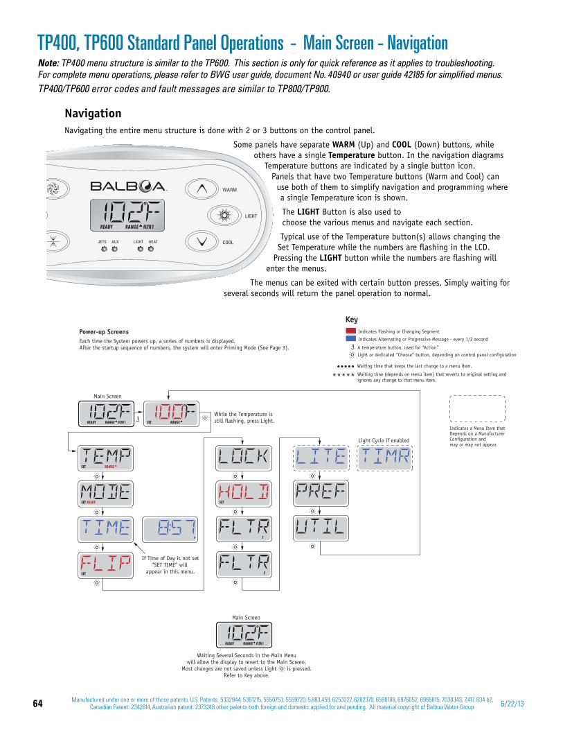
64 Manufactured under one or more of these patents. U.S. Patents: 5332944, 5361215, 5550753, 5559720, 5,883,459, 6253227, 6282370, 6590188, 6976052, 6965815, 7030343, 7,417, 834 b2, Canadian Patent: 2342614, Australian patent: 2373248 other patents both foreign and domestic applied for and pending. All material copyright of Balboa Water Group. 6/22/13
Note: TP400 menu structure is similar to the TP600. This section is only for quick reference as it applies to troubleshooting. For complete menu operations, please refer to BWG user guide, document No. 40940 or user guide 42185 for simplified menus.TP400/TP600 error codes and fault messages are similar to TP800/TP900.
NavigationNavigating the entire menu structure is done with 2 or 3 buttons on the control panel.
Some panels have separate WARM (Up) and COOL (Down) buttons, while others have a single Temperature button. In the navigation diagrams
Temperature buttons are indicated by a single button icon.Panels that have two Temperature buttons (Warm and Cool) can
use both of them to simplify navigation and programming where a single Temperature icon is shown.
The LIGHT Button is also used to choose the various menus and navigate each section.
Typical use of the Temperature button(s) allows changing the Set Temperature while the numbers are fl ashing in the LCD.
Pressing the LIGHT button while the numbers are fl ashing will enter the menus.
The menus can be exited with certain button presses. Simply waiting for several seconds will return the panel operation to normal.
TP400, TP600 Standard Panel Operations Main Screen - Navigation-
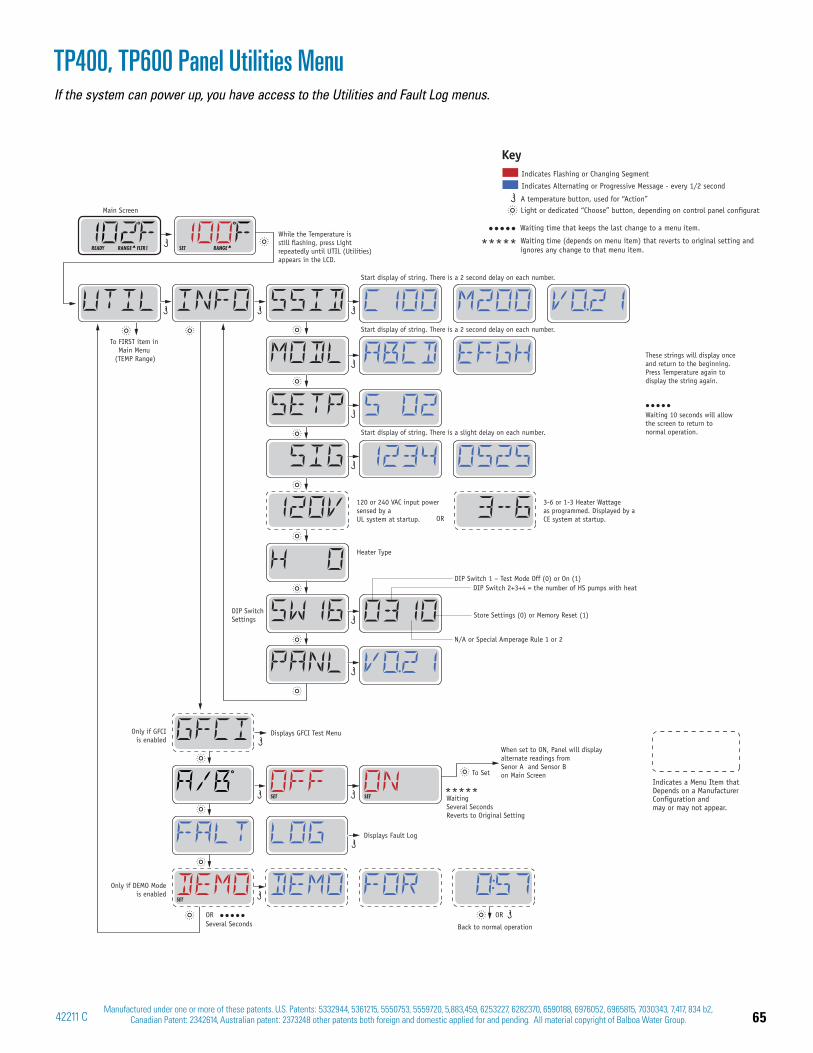
65Manufactured under one or more of these patents. U.S. Patents: 5332944, 5361215, 5550753, 5559720, 5,883,459, 6253227, 6282370, 6590188, 6976052, 6965815, 7030343, 7,417, 834 b2,
Canadian Patent: 2342614, Australian patent: 2373248 other patents both foreign and domestic applied for and pending. All material copyright of Balboa Water Group.42211 C
TP400, TP600 Panel Utilities MenuIf the system can power up, you have access to the Utilities and Fault Log menus.
See Page 17
See Page 18
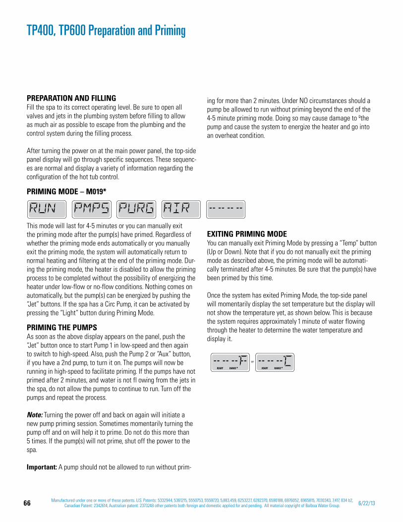
66 Manufactured under one or more of these patents. U.S. Patents: 5332944, 5361215, 5550753, 5559720, 5,883,459, 6253227, 6282370, 6590188, 6976052, 6965815, 7030343, 7,417, 834 b2, Canadian Patent: 2342614, Australian patent: 2373248 other patents both foreign and domestic applied for and pending. All material copyright of Balboa Water Group. 6/22/13
PREPARATION AND FILLINGFill the spa to its correct operating level. Be sure to open all valves and jets in the plumbing system before filling to allow as much air as possible to escape from the plumbing and the control system during the filling process.
After turning the power on at the main power panel, the top-side panel display will go through specific sequences. These sequenc-es are normal and display a variety of information regarding the configuration of the hot tub control.
PRIMING MODE – M019*
This mode will last for 4-5 minutes or you can manually exit the priming mode after the pump(s) have primed. Regardless of whether the priming mode ends automatically or you manually exit the priming mode, the system will automatically return to normal heating and filtering at the end of the priming mode. Dur-ing the priming mode, the heater is disabled to allow the priming process to be completed without the possibility of energizing the heater under low-flow or no-flow conditions. Nothing comes on automatically, but the pump(s) can be energized by pushing the “Jet” buttons. If the spa has a Circ Pump, it can be activated by pressing the “Light” button during Priming Mode.
PRIMING THE PUMPSAs soon as the above display appears on the panel, push the “Jet” button once to start Pump 1 in low-speed and then again to switch to high-speed. Also, push the Pump 2 or “Aux” button, if you have a 2nd pump, to turn it on. The pumps will now be running in high-speed to facilitate priming. If the pumps have not primed after 2 minutes, and water is not fl owing from the jets in the spa, do not allow the pumps to continue to run. Turn off the pumps and repeat the process.
Note: Turning the power off and back on again will initiate a new pump priming session. Sometimes momentarily turning the pump off and on will help it to prime. Do not do this more than 5 times. If the pump(s) will not prime, shut off the power to the spa.
Important: A pump should not be allowed to run without prim-
ing for more than 2 minutes. Under NO circumstances should a pump be allowed to run without priming beyond the end of the 4-5 minute priming mode. Doing so may cause damage to ºthe pump and cause the system to energize the heater and go into an overheat condition.
TP400, TP600 Preparation and Priming
EXITING PRIMING MODEYou can manually exit Priming Mode by pressing a “Temp” button (Up or Down). Note that if you do not manually exit the priming mode as described above, the priming mode will be automati-cally terminated after 4-5 minutes. Be sure that the pump(s) have been primed by this time.
Once the system has exited Priming Mode, the top-side panel will momentarily display the set temperature but the display will not show the temperature yet, as shown below. This is because the system requires approximately 1 minute of water flowing through the heater to determine the water temperature and display it.
READY RANGE READY RANGE
or
67Manufactured under one or more of these patents. U.S. Patents: 5332944, 5361215, 5550753, 5559720, 5,883,459, 6253227, 6282370, 6590188, 6976052, 6965815, 7030343, 7,417, 834 b2,
Canadian Patent: 2342614, Australian patent: 2373248 other patents both foreign and domestic applied for and pending. All material copyright of Balboa Water Group.42211 C
DEMO (DEMO MODE)Demo Mode is not always enabled, so it may not appear. This is designed to operate several devices in a sequence in order to demonstrate the various features of a particular hot tub.
INFO (SYSTEM INFORMATION SUB-MENU)The System Information Menu displays various settings and identification of the particular system. As each item in the menu is highlighted, the detail for that item is displayed at the bottom of the screen.
SSID (SOFTWARE ID)Displays the software ID number for the System.
MODL (SYSTEM MODEL)Displays the Model Number of the System.
SETP (CURRENT SETUP)Displays the currently selected Configuration Setup Number.
SIG (CONFIGURATION SIGNATURE)Displays the checksum for the system configuration file.
HEATER VOLTAGE (FEATURE NOT USED ON CE RATED SYSTEMS)Displays the operating voltage configured for the heater.
HEATER WATTAGE AS CONFIGURED IN SOFTWARE (CE SYSTEMS ONLY)Displays a heater kilowatt rating as programmed into the control system software (1-3 or 3-6).
H _ (HEATER TYPE)Displays a heater type ID number.
SW _ (DIP SWITCH SETTINGS)Displays a number that represents the DIP switch positions of S1 on the main circuit board.
PANL (PANEL VERSION)Displays a number of the software in the topside control panel.
GFCI (GFCI Test) (Feature not available on CE rated systems.)GFCI Test is not always enabled, so it may not appear. This screen allows the GFCI to be tested manually from the panel and can be used to reset the automatic test feature. If the GFCI Test Feature is reset, the device will trip within 7 days.
TP400, TP600 Message CodesThe following are messages and features that can appear on the TP400 and TP600 panels.NOTE: LCD readouts may look slightly different than shown on screen.
MESSAGE CODES (Found on the pages listed)M0[XX] numbers are Message Codes 55M015 62, 69M016 59, 68M017 59, 68M019 68M019* 55M020 62, 69M021 62, 69M022 62, 69M026 62, 69M027 59M028 59, 68M029 62, 68M030 59, 68M031 69M031, Sensor A: 62M032 69M032, Sensor B: 62M033 68M034 62, 69M035 62, 69M036 62, 69M037* 57
68 Manufactured under one or more of these patents. U.S. Patents: 5332944, 5361215, 5550753, 5559720, 5,883,459, 6253227, 6282370, 6590188, 6976052, 6965815, 7030343, 7,417, 834 b2, Canadian Patent: 2342614, Australian patent: 2373248 other patents both foreign and domestic applied for and pending. All material copyright of Balboa Water Group. 6/22/13
A / B (A/B SENSOR TEMPERATURES)When this is set to On, the temperature display will alternate to display temperature from Sensor A and Sensor B in the heater.
FALT LOG (FAULT LOG)The Fault Log is a record of the last 24 faults that can be re-viewed by a service tech.
SCROLLING TP400/TP600 MESSAGESThe following messages will scroll across the TP400/TP600 pan-els. NOTE: LCD readouts may look slightly different than shown on screen.
RUN PMPS PURG AIR ----
PRIMING MODE – M019Each time the spa is powered up, it will enter Priming Mode. The purpose of Priming Mode is to allow the user to run each pump and manually verify that the pumps are primed (air is purged) and water is flowing. This typically requires observing the output of each pump separately, and is generally not possible in normal operation. Priming Mode lasts 4 minutes, but you can exit it earlier by pressing any Temp button. The heater is not allowed to run during Priming Mode.NOTE: If your spa has a Circ Pump, it will turn on with Jets 1 in Priming Mode. The Circ Pump will run by itself when Priming Mode is exited.
-- -- -- F -- -- -- C Water Temperature is Unknown
After the pump has been running for 1 minute, the temperature will be displayed.
42 F TOO COLDToo Cold - Freeze Protection
A potential freeze condition has been detected, or the Aux Freeze Switch has closed, and all pumps and blower are activated. All pumps and blower are ON for at least 4 minutes after the poten-tial freeze condition has ended, or when the aux freeze switch opens. In some cases, pumps may turn on and off and the heater may operate during Freeze Protection. This is an operational message, not an error indication.
WATR TOO HOT -- -- -- -- Water is too Hot (OHS) – M029
One of the water temp sensors has detected spa water temp 110°F (43.3°C) and spa functions are disabled. System will auto reset when the spa water temp is below 108°F (42.2°C). Check for extended pump operation or high ambient temp.
SFTY TRIP -- -- -- -- Safety Trip - Pump Suction Blockage* – M033
The Safety Trip error message indicates that the vacuum switch has closed. This occurs when there has been a suction problem or a possible entrapment situation avoided. (Note: not all spas have this feature.)
HTR FLOW LOSS -- -- -- --Heater Flow is Reduced (HFL) – M016
There may not be enough water flow through the heater to carry the heat away from the heating element. Heater start up will begin again after about 1 min. See “Flow Related Checks” below.
HTR FLOW FAIL -- -- -- -- Heater Flow is Reduced (LF)* – M017
There is not enough water flow through the heater to carry the heat away from the heating element and the heater has been disabled. See “Flow Related Checks” below. After the problem has been resolved, you must press any button to reset and begin heater start up.
HTR MAY BE DRY -- -- -- -- WAIT -- -- -- --Heater May be Dry (dr)* – M028
Possible dry heater, or not enough water in the heater to start it. The spa is shut down for 15 min. Press any button to reset the heater start-up. See “Flow Related Checks” below.
HTR TOO HOT -- -- -- --HTR is too Hot (OHH)* M030
One of the water temp sensors has detected 118°f (47.8°C) in the heater and the spa is shut down. You must press any button to reset when water is below 108°f (42.2°C). See “Flow Related Checks” below.
TP400, TP600 Messages (cont.)
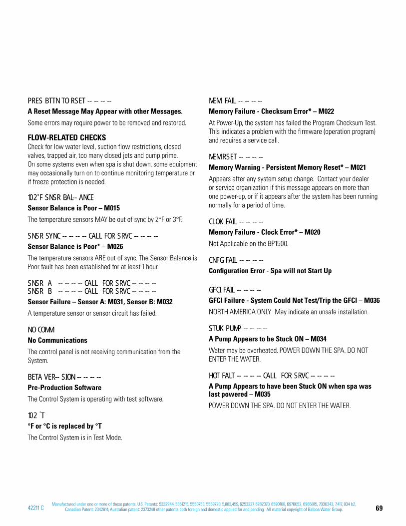
69Manufactured under one or more of these patents. U.S. Patents: 5332944, 5361215, 5550753, 5559720, 5,883,459, 6253227, 6282370, 6590188, 6976052, 6965815, 7030343, 7,417, 834 b2,
Canadian Patent: 2342614, Australian patent: 2373248 other patents both foreign and domestic applied for and pending. All material copyright of Balboa Water Group.42211 C
PRES BTTN TO RSET -- -- -- --A Reset Message May Appear with other Messages.
Some errors may require power to be removed and restored.
FLOW-RELATED CHECKSCheck for low water level, suction flow restrictions, closed valves, trapped air, too many closed jets and pump prime. On some systems even when spa is shut down, some equipment may occasionally turn on to continue monitoring temperature or if freeze protection is needed.
102˚F SNSR BAL-- ANCESensor Balance is Poor – M015
The temperature sensors MAY be out of sync by 2°F or 3°F.
SNSR SYNC -- -- -- -- CALL FOR SRVC -- -- -- --Sensor Balance is Poor* – M026
The temperature sensors ARE out of sync. The Sensor Balance is Poor fault has been established for at least 1 hour.
SNSR A -- -- -- -- CALL FOR SRVC -- -- -- -- SNSR B -- -- -- -- CALL FOR SRVC -- -- -- --Sensor Failure – Sensor A: M031, Sensor B: M032
A temperature sensor or sensor circuit has failed.
NO COMMNo Communications
The control panel is not receiving communication from the System.
BETA VER-- SION -- -- -- --Pre-Production Software
The Control System is operating with test software.
102 T°F or °C is replaced by °T
The Control System is in Test Mode.
MEM FAIL -- -- -- --Memory Failure - Checksum Error* – M022
At Power-Up, the system has failed the Program Checksum Test. This indicates a problem with the firmware (operation program) and requires a service call.
MEM RSET -- -- -- --Memory Warning - Persistent Memory Reset* – M021
Appears after any system setup change. Contact your dealer or service organization if this message appears on more than one power-up, or if it appears after the system has been running normally for a period of time.
CLOK FAIL -- -- -- --Memory Failure - Clock Error* – M020
Not Applicable on the BP1500.
CNFG FAIL -- -- -- --Configuration Error - Spa will not Start Up
GFCI FAIL -- -- -- --GFCI Failure - System Could Not Test/Trip the GFCI – M036
NORTH AMERICA ONLY. May indicate an unsafe installation.
STUK PUMP -- -- -- -- A Pump Appears to be Stuck ON – M034
Water may be overheated. POWER DOWN THE SPA. DO NOT ENTER THE WATER.
HOT FALT -- -- -- -- CALL FOR SRVC -- -- -- -- A Pump Appears to have been Stuck ON when spa was last powered – M035
POWER DOWN THE SPA. DO NOT ENTER THE WATER.
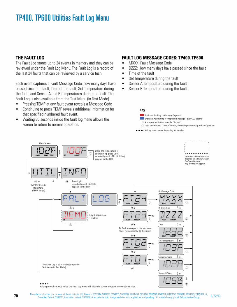
70 Manufactured under one or more of these patents. U.S. Patents: 5332944, 5361215, 5550753, 5559720, 5,883,459, 6253227, 6282370, 6590188, 6976052, 6965815, 7030343, 7,417, 834 b2, Canadian Patent: 2342614, Australian patent: 2373248 other patents both foreign and domestic applied for and pending. All material copyright of Balboa Water Group. 6/22/13
TP400, TP600 Utilities Fault Log Menu
THE FAULT LOG The Fault Log stores up to 24 events in memory and they can be reviewed under the Fault Log Menu. The Fault Log is a record of the last 24 faults that can be reviewed by a service tech.
Each event captures a Fault Message Code, how many days have passed since the fault, Time of the fault, Set Temperature during the fault, and Sensor A and B temperatures during the fault. The Fault Log is also available from the Test Menu (in Test Mode).
Pressing TEMP at any fault event reveals a Message CodeContinuing to press TEMP reveals additional information for that specified numbered fault event.Waiting 30 seconds inside the fault log menu allows the screen to return to normal operation.
FAULT LOG MESSAGE CODES: TP400, TP600MXXX: Fault Message CodeDZZZ: How many days have passed since the faultTime of the faultSet Temperature during the faultSensor A Temperature during the faultSensor B Temperature during the fault
Only if DEMO Modeis enabled
The Fault Log is also available from the Test Menu (in Test Mode).
M: Message Code
M:
M:
M:
D: Days Ago
Time
Set Temperature
Sensor A Temp
Sensor B Temp
24 Fault messages is the maximum.Fewer messages may be displayed.
To FIRST item in Main Menu
(TEMP Range)
While the Temperature is still flashing, press Lightrepeatedly until UTIL (Utilities)appears in the LCD.
Press Lightrepeatedly until FALT LOGappears in the LCD.
SET RANGE
Main Screen
READY RANGE FLTR1
READY RANGE
SET READY RANGE
READY RANGE
READY RANGE
READY RANGE
READY RANGE
READY RANGE P
Waiting several seconds inside the Fault Log Menu will allow the screen to return to normal operation.
Indicates Flashing or Changing Segment
Key
A temperature button, used for “Action” Light or dedicated “Choose” button, depending on control panel configuration
Indicates Alternating or Progressive Message - every 1/2 second
Waiting time - varies depending on function
Indicates a Menu Item thatDepends on a ManufacturerConfiguration and may or may not appear.
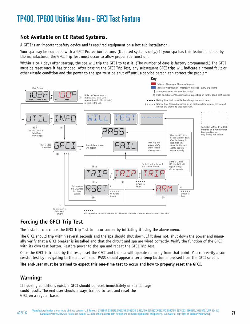
71Manufactured under one or more of these patents. U.S. Patents: 5332944, 5361215, 5550753, 5559720, 5,883,459, 6253227, 6282370, 6590188, 6976052, 6965815, 7030343, 7,417, 834 b2,
Canadian Patent: 2342614, Australian patent: 2373248 other patents both foreign and domestic applied for and pending. All material copyright of Balboa Water Group.42211 C
Not Available on CE Rated Systems.A GFCI is an important safety device and is required equipment on a hot tub installation.
Your spa may be equipped with a GFCI Protection feature. (UL rated systems only.) If your spa has this feature enabled by the manufacturer, the GFCI Trip Test must occur to allow proper spa function.
Within 1 to 7 days after startup, the spa will trip the GFCI to test it. (The number of days is factory programmed.) The GFCI must be reset once it has tripped. After passing the GFCI Trip Test, any subsequent GFCI trips will indicate a ground fault or other unsafe condition and the power to the spa must be shut off until a service person can correct the problem.
Forcing the GFCI Trip TestThe installer can cause the GFCI Trip Test to occur sooner by initiating it using the above menu.
The GFCI should trip within several seconds and the spa should shut down. If it does not, shut down the power and manu-ally verify that a GFCI breaker is installed and that the circuit and spa are wired correctly. Verify the function of the GFCI with its own test button. Restore power to the spa and repeat the GFCI Trip Test.
Once the GFCI is tripped by the test, reset the GFCI and the spa will operate normally from that point. You can verify a suc-cessful test by navigating to the above menu. PASS should appear after a temp button is pressed from the GFCI screen.
The end-user must be trained to expect this one-time test to occur and how to properly reset the GFCI.
Warning:If freezing conditions exist, a GFCI should be reset immediately or spa damage could result. The end user should always trained to test and reset the GFCI on a regular basis.
TP400, TP600 Utilities Menu - GFCI Test Feature
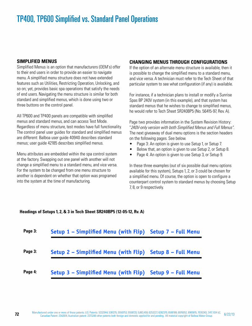
72 Manufactured under one or more of these patents. U.S. Patents: 5332944, 5361215, 5550753, 5559720, 5,883,459, 6253227, 6282370, 6590188, 6976052, 6965815, 7030343, 7,417, 834 b2, Canadian Patent: 2342614, Australian patent: 2373248 other patents both foreign and domestic applied for and pending. All material copyright of Balboa Water Group. 6/22/13
TP400, TP600 Simplified vs. Standard Panel Operations
SIMPLIFIED MENUSSimplified Menus is an option that manufacturers (OEM's) offer to their end users in order to provide an easier to navigate menu. A simplified menu structure does not have extended features such as Utilities, Restricting Operation, Unlocking, and so on; yet, provides basic spa operations that satisfy the needs of end users. Navigating the menu structure is similar for both standard and simplified menus, which is done using two or three buttons on the control panel.
All TP600 and TP400 panels are compatible with simplified menus and standard menus, and can access Test Mode. Regardless of menu structure, test modes have full functionality. The control panel user guides for standard and simplified menus are different: Balboa user guide 40940 describes standard menus; user guide 42185 describes simplified menus.
Menu attributes are embedded within the spa control system at the factory. Swapping out one panel with another will not change a simplified menu to a standard menu, and vice versa. For the system to be changed from one menu structure to another is dependent on whether that option was programed into the system at the time of manufacturing.
CHANGING MENUS THROUGH CONFIGURATIONSIf the option of an alternate menu structure is available, then it is possible to change the simplified menu to a standard menu, and vice versa. A technician must refer to the Tech Sheet of that particular system to see what configuration (if any) is available.
For instance, if a technician plans to install or modify a Sunrise Spas BP 240V system (in this example), and that system has standard menus that he wishes to change to simplified menus, he would refer to Tech Sheet SR240BP5 (No. 56415-97, Rev. A).
Page two provides information in the System Revision History: "240V-only version with both Simplified Menus and Full Menus".The next giveaway of dual menu options is the section headers on the following pages. See below.
Page 3: An option is given to use Setup 1, or Setup 7.Below that, an option is given to use Setup 2, or Setup 8. Page 4: An option is given to use Setup 3, or Setup 9.
In these three examples (out of six possible dual menu options available for this system), Setups 1, 2, or 3 could be chosen for a simplified menu. Of course, the option is open to configure a counterpart control system to standard menus by choosing Setup 7, 8, or 9 respectively.
Setup 1 – Simplified Menu (with Flip) Setup 7 – Full Menu
Setup 2 – Simplified Menu (with Flip) Setup 8 – Full Menu
Setup 3 – Simplified Menu (with Flip) Setup 9 – Full Menu
Headings of Setups 1, 2, & 3 in Tech Sheet SR240BP5 (12-05-12, Rv. A)
Page 3:
Page 3:
Page 4:
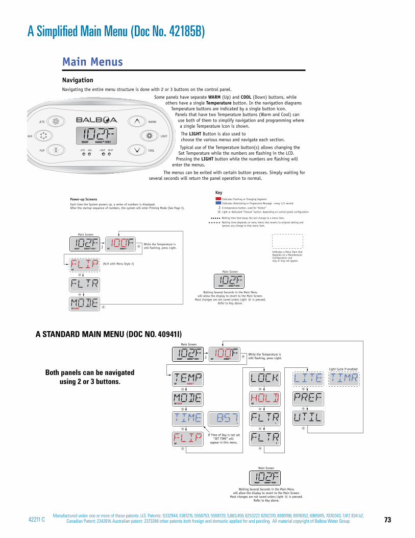
73Manufactured under one or more of these patents. U.S. Patents: 5332944, 5361215, 5550753, 5559720, 5,883,459, 6253227, 6282370, 6590188, 6976052, 6965815, 7030343, 7,417, 834 b2,
Canadian Patent: 2342614, Australian patent: 2373248 other patents both foreign and domestic applied for and pending. All material copyright of Balboa Water Group.42211 C
A Simplified Main Menu (Doc No. 42185B)
A STANDARD MAIN MENU (DOC NO. 40941I)
Main MenusNavigationNavigating the entire menu structure is done with 2 or 3 buttons on the control panel.
Some panels have separate WARM (Up) and COOL (Down) buttons, while others have a single Temperature button. In the navigation diagrams
Temperature buttons are indicated by a single button icon.Panels that have two Temperature buttons (Warm and Cool) can
use both of them to simplify navigation and programming where a single Temperature icon is shown.
The LIGHT Button is also used to choose the various menus and navigate each section.
Typical use of the Temperature button(s) allows changing the Set Temperature while the numbers are fl ashing in the LCD.
Pressing the LIGHT button while the numbers are fl ashing will enter the menus.
The menus can be exited with certain button presses. Simply waiting for several seconds will return the panel operation to normal.
Main Screen
P
SET RANGE
SET
While the Temperature is still flashing, press Light.SET RANGEREADY RANGE FLTR1
Main Screen
READY RANGE FLTR1
SETREADYSET
1
2
Light Cycle if enabled
Waiting Several Seconds in the Main Menuwill allow the display to revert to the Main Screen.
Most changes are not saved unless Light is pressed.Refer to Key above.
If Time of Day is not set“SET TIME” will
appear in this menu.
Both panels can be navigated using 2 or 3 buttons.
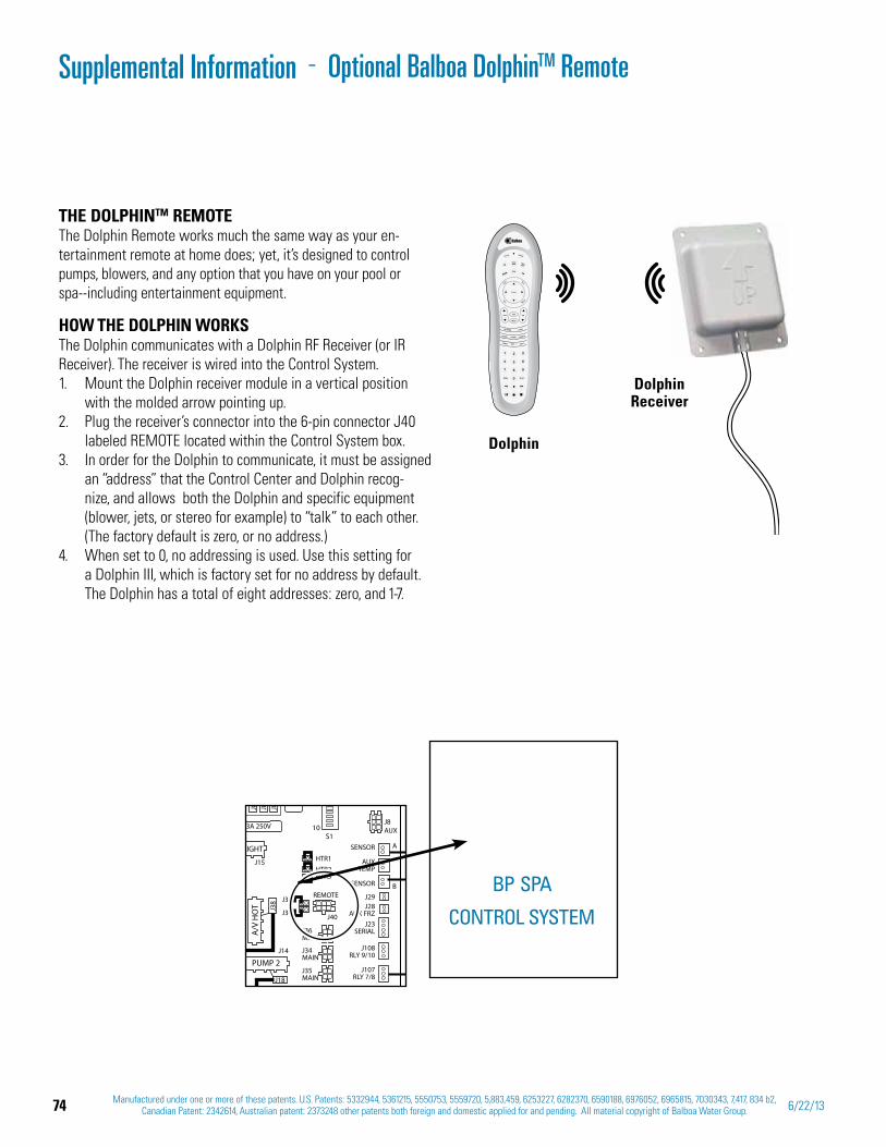
74 Manufactured under one or more of these patents. U.S. Patents: 5332944, 5361215, 5550753, 5559720, 5,883,459, 6253227, 6282370, 6590188, 6976052, 6965815, 7030343, 7,417, 834 b2, Canadian Patent: 2342614, Australian patent: 2373248 other patents both foreign and domestic applied for and pending. All material copyright of Balboa Water Group. 6/22/13
AUX
J8AUX
J36MAIN
J34MAIN
J35MAIN
3A 250V
J8J8J8
J15
J14
J38
HTR1HTR2HTR3
REMOTEJ31
J30 J40
10S1
LIGHT
A/V
HO
T
J18
PUMP 2J107
RLY 7/8
J108RLY 9/10
J23SERIAL
J29
SENSOR
AUXTEMP
J28AUX FRZ
A
SENSOR B
THE DOLPHINTM REMOTEThe Dolphin Remote works much the same way as your en-tertainment remote at home does; yet, it’s designed to control pumps, blowers, and any option that you have on your pool or spa--including entertainment equipment.
HOW THE DOLPHIN WORKSThe Dolphin communicates with a Dolphin RF Receiver (or IR Receiver). The receiver is wired into the Control System.
Mount the 1. Dolphin receiver module in a vertical position with the molded arrow pointing up. Plug the 2. receiver’s connector into the 6-pin connector J40 labeled REMOTE located within the Control System box.In order for the Dolphin to communicate, it must be assigned 3. an “address” that the Control Center and Dolphin recog-nize, and allows both the Dolphin and specific equipment (blower, jets, or stereo for example) to “talk” to each other. (The factory default is zero, or no address.) When set to 0, no addressing is used. Use this setting for 4. a Dolphin III, which is factory set for no address by default. The Dolphin has a total of eight addresses: zero, and 1-7.
Dolphin
BP SPA
CONTROL SYSTEM
Dolphin Receiver
Supplemental Information Optional Balboa DolphinTM Remote-
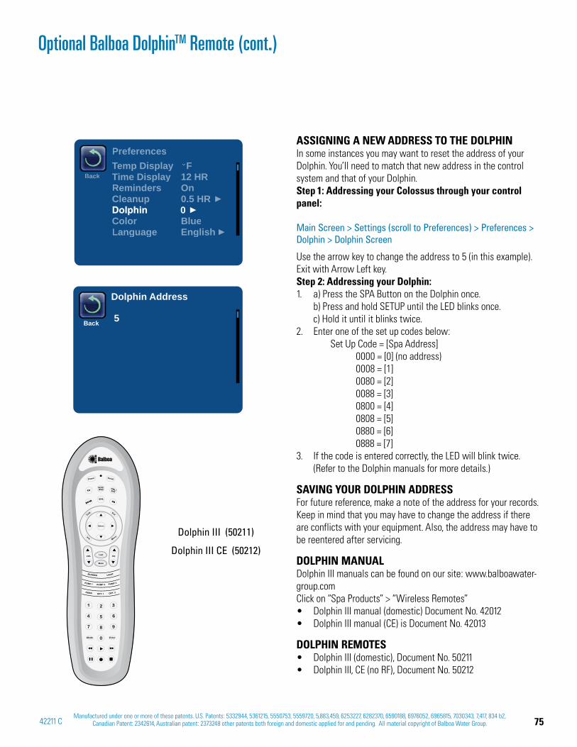
75Manufactured under one or more of these patents. U.S. Patents: 5332944, 5361215, 5550753, 5559720, 5,883,459, 6253227, 6282370, 6590188, 6976052, 6965815, 7030343, 7,417, 834 b2,
Canadian Patent: 2342614, Australian patent: 2373248 other patents both foreign and domestic applied for and pending. All material copyright of Balboa Water Group.42211 C
Back 5
Dolphin Address
Preferences
BackTemp Display FTime Display 12 HRReminders OnCleanup 0.5 HRDolphinColor BlueLanguage English
0
Dolphin III (50211)
Dolphin III CE (50212)
ASSIGNING A NEW ADDRESS TO THE DOLPHIN In some instances you may want to reset the address of your Dolphin. You’ll need to match that new address in the control system and that of your Dolphin. Step 1: Addressing your Colossus through your control panel:
Main Screen > Settings (scroll to Preferences) > Preferences > Dolphin > Dolphin Screen
Use the arrow key to change the address to 5 (in this example). Exit with Arrow Left key.Step 2: Addressing your Dolphin:
a) Press the SPA Button on the Dolphin once. 1. b) Press and hold SETUP until the LED blinks once. c) Hold it until it blinks twice.Enter one of the 2. set up codes below:
Set Up Code = [Spa Address]0000 = [0] (no address)0008 = [1]0080 = [2]0088 = [3]0800 = [4]0808 = [5]0880 = [6]0888 = [7]
If the code is entered correctly, the LED will blink twice. 3. (Refer to the Dolphin manuals for more details.)
SAVING YOUR DOLPHIN ADDRESSFor future reference, make a note of the address for your records. Keep in mind that you may have to change the address if there are conflicts with your equipment. Also, the address may have to be reentered after servicing.
DOLPHIN MANUAL Dolphin III manuals can be found on our site: www.balboawater-group.comClick on “Spa Products” > “Wireless Remotes”
Dolphin III manual (domestic) Document No. 42012Dolphin III manual (CE) is Document No. 42013
DOLPHIN REMOTESDolphin III (domestic), Document No. 50211Dolphin III, CE (no RF), Document No. 50212
Optional Balboa DolphinTM Remote (cont.)
76 Manufactured under one or more of these patents. U.S. Patents: 5332944, 5361215, 5550753, 5559720, 5,883,459, 6253227, 6282370, 6590188, 6976052, 6965815, 7030343, 7,417, 834 b2, Canadian Patent: 2342614, Australian patent: 2373248 other patents both foreign and domestic applied for and pending. All material copyright of Balboa Water Group. 6/22/13
The heater requires at least 20 Gallons per Minute (1. GPM) of flow for proper function.Some systems may require at least 25 GPM.2. The suction system for the 2-speed pump or for the circ 3. pump must be dedicated. There must not be any other pumps connected to this suction system. The suction system for the 2-speed pump or for the circ 4. pump must include the following: a. 2 suction fittings, or b. 1 suction fitting and a skimmer. If the suction system for the 2-speed pump or for the circ 5. pump includes a filter, it is desirable that the filter incor-porate a by-pass around the filter cartridge that opens when the cartridge gets dirty. (Spring tension holding the by-pass valve closed must be overcome by the vacuum of the pump.) This by-pass should be capable of flowing a minimum of 20 GPM during the low speed operation of the 2-speed pump or during circ pump operation with the cartridge 100% blocked. The inclusion of a suction fitting appropriately plumbed into the suction circuit in conjunc-tion with a vacuum filter may also meet this requirement. The pressure system for the 2-speed pump or for the circ 6. pump must be dedicated. There must not be any other pumps connected to this pressure system. The pressure system for the 2-speed pump or for the circ 7. pump must discharge water freely into the spa. If the pressure system for the 2-speed pump includes 8. a diverter valve, or a diverter jet, there must not be an “off” position that would stop water flow from the pump or any other position that would throttle or reduce water flow from the pump.If the pressure system for the 2-speed pump includes 9. flow adjustable jets that can be 100% closed, at least 2 non-adjustable jets must be included in each possible inlet circuit so that a minimum of 20 GPM can flow during low pump operation with all the jets closed. Any other means of by-passing flow around the closed jets is acceptable as long as the by-pass means is down stream from the heater and allows a minimum of 20 GPM to flow through the heater during low speed operation. If the pressure system for the 2-speed pump includes 10. flow adjustable jets that do not close 100%, at least 20
GPM must flow during low speed operation through each possible inlet circuit with all the jets closed. If the pressure system for a 2-speed pump or for a circ pump 11. includes a filter, the filter must be equipped with a by-pass around the cartridge that opens when the cartridge gets dirty. (Spring tension holding the by-pass valve closed must be overcome by the pressure of the pump.) This by-pass must be capable of flowing a minimum of 20 GPM during low pump operation with the cartridge 100% blocked. If the pressure system for a 2-speed pump or for a circ pump 12. includes branch circulation lines such as circuits intended to operate ozone injection systems, these branch circulation lines must be connected downstream from the heater. Avoid inter-connection of the plumbing circuits for the 13. 2-speed pump or for the circ pump with other pumps in the spa plumbing system for the purpose of freeze protection. The Colossus control system will provide freeze protection. There is also provision for remote sensing freeze protection if required. Position inlets and jets in the spa so that they do not direct 14. water flow towards suction fittings or skimmers. This will avoid a “thermal short circuit” and prevent excessive heater and pump cycling. If service valves are a part of the circulation system for the 15. 2-speed pump or for the circ pump, be sure to use valves that incorporate a means of “locking” in the open position. If the 2-speed pump or the circ pump is replaced in the field 16. by service personnel, the replacement used must equal or exceed the hydraulic specifications of the original pump.To assure adequate performance, the spa plumbing must be 17. 1-1⁄2” minimum. The use of 2” is highly recommended. Either schedule 40 or flexible PVC pipe is acceptable.It is recommended that shut-off valves be installed in the 18. suction and discharge lines.
Below are guidelines when designing replacing an older control system, or if designing a new spa system. This information is included in order to offer more insight into spa plumbing and mechanics.
Spa Guidelines to Keep in Mind
77Manufactured under one or more of these patents. U.S. Patents: 5332944, 5361215, 5550753, 5559720, 5,883,459, 6253227, 6282370, 6590188, 6976052, 6965815, 7030343, 7,417, 834 b2,
Canadian Patent: 2342614, Australian patent: 2373248 other patents both foreign and domestic applied for and pending. All material copyright of Balboa Water Group.42211 C
CIRC PUMP (OR CIRCULATION PUMP) Low horse power pump designated especially for maintenance of filtration and heating. It often runs all day.
CLEAN-UP (OR PURGE) CYCLEAn action designed to circulate water to maintain sanitary condi-tions. Pumps or blowers purge standing water to prevent the water from becoming stagnant.
FILTRATION CYCLEPeriod of time designated to filter the system. Oftentimes there are two filter cycles, 12 hours apart, and designated as F1 and F2.
FREEZE PROTECTIONA safety feature detecting water or air temperature approaching freezing. Once a set low temperature is reached, an action is often initiated automatically. Oftentimes pumps will start to keep water circulating in all plumbing and the heater may operate.
GFCIA device intended to protect people in the event of an electrical malfunction. Spa owners should know how to test the GFCI as routine maintenance.
PREFERENCESProgrammed events according to personal preferences.
SSIDSoftware Self Identification (or, System Panel ID)
PROGRAMMING Setting an order and time for planned events, such as filter times, clean-up cycle, etc.
PRIMING MODEAct of water flow through the plumbing to purge air from the spa system. Normally, priming mode can be bypassed. The prim-ing mode is necessary only if the spa is refilled and if there’s the possibility of air being in the system.
WHAT PRIMING MODE DOES:Each time the spa is powered up, it will enter Priming Mode. The
Glossary
purpose of Priming Mode is to allow the user to run each pump and manually verify that the pumps are primed (air is purged) and water is flowing. This typically requires observing the output of each pump separately, and is generally not possible in normal operation. Priming Mode lasts 4 minutes, but you can exit it earlier by pressing any Temp button. The heater is not allowed to run during Priming Mode. NOTE: If your spa has a Circ Pump, it will turn on with Jets 1 in Priming Mode. The Circ Pump will run by itself when Priming Mode is exited.
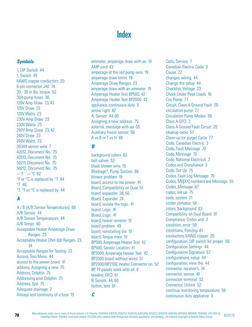
78 Manufactured under one or more of these patents. U.S. Patents: 5332944, 5361215, 5550753, 5559720, 5,883,459, 6253227, 6282370, 6590188, 6976052, 6965815, 7030343, 7,417, 834 b2, Canadian Patent: 2342614, Australian patent: 2373248 other patents both foreign and domestic applied for and pending. All material copyright of Balboa Water Group. 6/22/13
Symbols
1, DIP Switch 441, Switch 456AWG copper conductors 206-pin connector J40 7430 - 35 in lbs. torque 5230A pump fuses 38120V Amp Draw 23, 42120V Draw 23120V Watts 23230V Amp Draw 23230V Watts 23240V Amp Draw 23, 42240V Draw 23240V Watts 2330344 sensor wire 742012, Document No. 7542013, Document No. 7550211, Document No. 7550212, Document No. 75---˚F ---˚C 62°F or °C is replaced by °T 44°T 46°T, °F or °C is replaced by 44
A
A / B (A/B Sensor Temperatures) 68A/B Sensor 44A/B Sensor Temperatures 44A/B Temps 60Acceptable Heater Amperage Draw
Ranges 23Acceptable Heater Ohm ( ) Ranges 23,
34Acceptable Ranges for Testing 23Access, Test Menu 44access to the power board 41address, Assigning a new 75Address, Dolphin 75Addressing your Dolphin 75Address, Spa 75Adequate drainage 2Always test continuity of a fuse 19
ammeter, amperage draw with an 19AMP cord 43amperage at the red pump wire 19amperage draw limits 19Amperage Draw Ranges 23amperage draw with an ammeter 19Amperage Heater Test BP500 42Amperage Heater Test BP2000 42appliance, continuous duty 3arrow, right 62A, Sensor 44, 60Assigning a new address 75asterisk, message with an 55Auxiliary freeze sensor 56A vs B or T vs H 48
B
background colors 63ball valves 52black blower wire 19Blockage*, Pump Suction 68blower problem 19board, access to the power 41Board, Compatibility on Dual 51board, expander 38, 50Board, Expander 24board, isolate the logic 41board, Logic 41Board, Logic 41board, newer revision 51board problem 49board, reinstalling the 51board, Torque main 51BP500, Amperage Heater Test 42BP500, Sensor Location 41BP2000, Amperage Heater Test 42BP2000 board without wires 51BP2000/BP2100, Heater Connector on 52BP, TP panels work with all 8breaker, GFCI 61B, Sensor 44, 60button, test 61
C
Calls, Service 7Canadian Electric Code 3Cause 22changes, wiring 44Change the setup 44Checklist, Voltage 23Check Under Peak Loads 16Circ Pump 77Circuit, Class A Ground Fault 20circulation pump 77Circulation Pump Modes 56Class A GFCI 2Class A Ground Fault Circuit 20cleanup cycle 57Clean-up (or purge) Cycle 77Code, Canadian Electric 3Code, Fault Message 70Code, Message 70Code, National Electrical 3Codes and Compliance 3Code, Set Up 75Codes, Fault Log Message 70Codes, M0[XX] numbers are Message 55Codes, Message 67codes, set up 75code, system 21colder climates 56colors, background 63Compatibility on Dual Board 51Compliance, Codes and 3condition, error 59conditions, freezing 61conductors, 6AWG copper 20configuration, DIP switch for proper 50Configuration Settings 44Configuration Signature 67configurations, setup 44configuration, view the 44connector, receiver’s 74connector, sensor 41connector, terminal 52Connector, Unlock 52continue monitoring temperature 59continuous duty appliance 3
Index
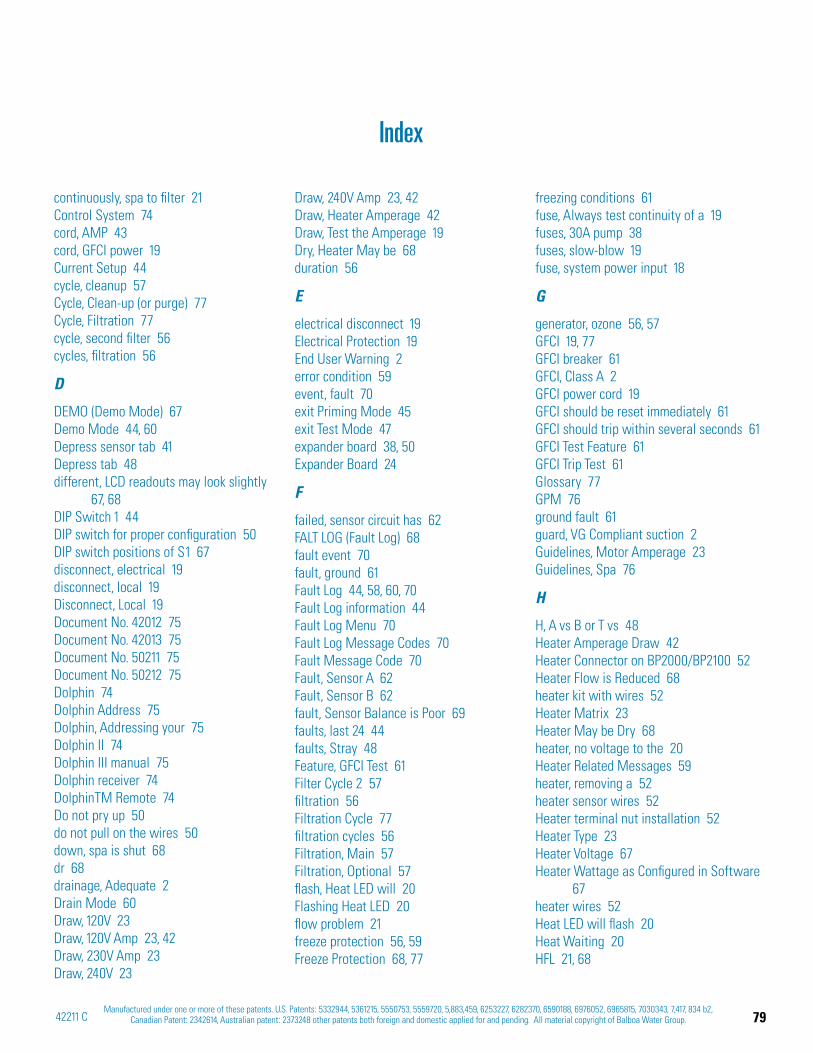
79Manufactured under one or more of these patents. U.S. Patents: 5332944, 5361215, 5550753, 5559720, 5,883,459, 6253227, 6282370, 6590188, 6976052, 6965815, 7030343, 7,417, 834 b2,
Canadian Patent: 2342614, Australian patent: 2373248 other patents both foreign and domestic applied for and pending. All material copyright of Balboa Water Group.42211 C
continuously, spa to filter 21Control System 74cord, AMP 43cord, GFCI power 19Current Setup 44cycle, cleanup 57Cycle, Clean-up (or purge) 77Cycle, Filtration 77cycle, second filter 56cycles, filtration 56
D
DEMO (Demo Mode) 67Demo Mode 44, 60Depress sensor tab 41Depress tab 48different, LCD readouts may look slightly
67, 68DIP Switch 1 44DIP switch for proper configuration 50DIP switch positions of S1 67disconnect, electrical 19disconnect, local 19Disconnect, Local 19Document No. 42012 75Document No. 42013 75Document No. 50211 75Document No. 50212 75Dolphin 74Dolphin Address 75Dolphin, Addressing your 75Dolphin II 74Dolphin III manual 75Dolphin receiver 74DolphinTM Remote 74Do not pry up 50do not pull on the wires 50down, spa is shut 68dr 68drainage, Adequate 2Drain Mode 60Draw, 120V 23Draw, 120V Amp 23, 42Draw, 230V Amp 23Draw, 240V 23
Draw, 240V Amp 23, 42Draw, Heater Amperage 42Draw, Test the Amperage 19Dry, Heater May be 68duration 56
E
electrical disconnect 19Electrical Protection 19End User Warning 2error condition 59event, fault 70exit Priming Mode 45exit Test Mode 47expander board 38, 50Expander Board 24
F
failed, sensor circuit has 62FALT LOG (Fault Log) 68fault event 70fault, ground 61Fault Log 44, 58, 60, 70Fault Log information 44Fault Log Menu 70Fault Log Message Codes 70Fault Message Code 70Fault, Sensor A 62Fault, Sensor B 62fault, Sensor Balance is Poor 69faults, last 24 44faults, Stray 48Feature, GFCI Test 61Filter Cycle 2 57filtration 56Filtration Cycle 77filtration cycles 56Filtration, Main 57Filtration, Optional 57flash, Heat LED will 20Flashing Heat LED 20flow problem 21freeze protection 56, 59Freeze Protection 68, 77
freezing conditions 61fuse, Always test continuity of a 19fuses, 30A pump 38fuses, slow-blow 19fuse, system power input 18
G
generator, ozone 56, 57GFCI 19, 77GFCI breaker 61GFCI, Class A 2GFCI power cord 19GFCI should be reset immediately 61GFCI should trip within several seconds 61GFCI Test Feature 61GFCI Trip Test 61Glossary 77GPM 76ground fault 61guard, VG Compliant suction 2Guidelines, Motor Amperage 23Guidelines, Spa 76
H
H, A vs B or T vs 48Heater Amperage Draw 42Heater Connector on BP2000/BP2100 52Heater Flow is Reduced 68heater kit with wires 52Heater Matrix 23Heater May be Dry 68heater, no voltage to the 20Heater Related Messages 59heater, removing a 52heater sensor wires 52Heater terminal nut installation 52Heater Type 23Heater Voltage 67Heater Wattage as Configured in Software
67heater wires 52Heat LED will flash 20Heat Waiting 20HFL 21, 68
Index
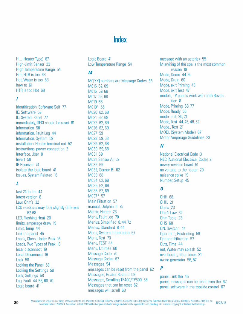
80 Manufactured under one or more of these patents. U.S. Patents: 5332944, 5361215, 5550753, 5559720, 5,883,459, 6253227, 6282370, 6590188, 6976052, 6965815, 7030343, 7,417, 834 b2, Canadian Patent: 2342614, Australian patent: 2373248 other patents both foreign and domestic applied for and pending. All material copyright of Balboa Water Group. 6/22/13
H _ (Heater Type) 67High-Limit Sensor 23High Temperature Range 54Hot, HTR is too 68Hot, Water is too 68how to 61HTR is too Hot 68
I
Identification, Software Self 77ID, Software 59ID, System Panel 77immediately, GFCI should be reset 61Information 58information, Fault Log 44Information, System 59installation, Heater terminal nut 52instructions, power connection 2Interface, User 8Invert 58IR Receiver 74isolate the logic board 41Issues, System Related 16
L
last 24 faults 44latest version 8Law, Ohm’s 32LCD readouts may look slightly different
67, 68LED, Flashing Heat 20limits, amperage draw 19Limit, Temp 44Link the panel 45Loads, Check Under Peak 16Loads, Two Types of Peak 16local disconnect 19Local Disconnect 19Lock 58Locking the Panel 58Locking the Settings 58Lock, Settings 58Log, Fault 44, 58, 60, 70Logic board 41
Logic Board 41Low Temperature Range 54
M
M0[XX] numbers are Message Codes 55M015 62, 69M016 59, 68M017 59, 68M019 68M019* 55M020 62, 69M021 62, 69M022 62, 69M026 62, 69M027 59M028 59, 68M029 62, 68M030 59, 68M031 69M031, Sensor A: 62M032 69M032, Sensor B: 62M033 68M034 62, 69M035 62, 69M036 62, 69M037* 57Main Filtration 57manual, Dolphin III 75Matrix, Heater 23Menu, Fault Log 70Menus, Simplified 8, 44, 72Menus, Standard 8, 44Menu, System Information 67Menu, Test 70Menu, TEST 44Menu, Utilities 60Message Code 70Message Codes 67Messages 54messages can be reset from the panel 62Messages, Heater Related 59Messages, Scrolling TP400/TP600 68Messages that can be reset 62messages will scroll 68
message with an asterisk 55Miswiring of the spa is the most common
reason 19Mode, Demo 44, 60Mode, Drain 60Mode, exit Priming 45Mode, exit Test 47models, TP panels work with both Revolu-
tion 8Mode, Priming 68, 77Mode, Ready 56mode, test 20, 21Mode, Test 44, 45, 46, 62Mode., Test 21MODL (System Model) 67Motor Amperage Guidelines 23
N
National Electrical Code 3NEC (National Electrical Code) 2newer revision board 51no voltage to the heater 20nuisance spike 19Number, Setup 45
O
OHH 68OHH. 21Ohms 23Ohm’s Law 32Ohm Table 23OHS 68ON, Switch 1 44Operation, Restricting 58Optional Filtration 57Outs, Time 44out, Water may splash 52overlapping filter times 21ozone generator 56, 57
P
panel, Link the 45panel, messages can be reset from the 62panel, software in the topside control 67
Index
81Manufactured under one or more of these patents. U.S. Patents: 5332944, 5361215, 5550753, 5559720, 5,883,459, 6253227, 6282370, 6590188, 6976052, 6965815, 7030343, 7,417, 834 b2,
Canadian Patent: 2342614, Australian patent: 2373248 other patents both foreign and domestic applied for and pending. All material copyright of Balboa Water Group.42211 C
panel stops operating 44panels, TP600/TP400 44panels, TP900/TP800 44Panel, Unlocking the 58Parts, Recommended 7PASS should appear 61period, time-out 56Pins, Sensor 49polling 56power connection instructions 2Preferences 77pressure, Water under 52prevent unwanted use 58Priming Mode 68, 77Problem 22problem, blower 19problem, board 49problem, flow 21problem, pump 19problem, sensor 49problem, suction 68programmable circ pump 56Programming 77Programming Reference 8properly reset the GFCI 61Protection, Electrical 19protection, freeze 56, 59Protection, Freeze 68, 77Pump, Circ 77pump, circulation 77pump problem 19pump, programmable circ 56Pumps, Troubleshooting 22Pump Suction Blockage* 68
R
Range, High Temperature 54Range, Low Temperature 54Ranges, Acceptable Heater Amperage
Draw 23Ranges, Acceptable Heater Ohm ( ) 23,
34Ranges, Amperage Draw 23
Ready Mode 56reason, Miswiring of the spa is the most
common 19receiver, Dolphin 74Receiver, IR 74Receiver, RF 74receiver’s connector 74Recommended Parts 7red TB1 terminal 18Reduced, Heater Flow is 68Ref. Card 40947 8Reference, Programming 8reinstalling the board 51release tab 50REMOTE 74Remote, DolphinTM 74removing a heater 52Replacment Sensor 49Required, Service Tools 7reset, Messages that can be 62reset the GFCI 61Resistance, Troubleshooting 34, 35Restricting Operation 58RF Receiver 74right arrow 62RUN PMPS PURG AIR ---- 68
S
S1 44S1, DIP switch positions of 67Safety Trip 68Screen, Spa 56Scrolling TP400/TP600 Messages 68scroll, messages will 68second filter cycle 56Sensor A 44, 60Sensor, A/B 44Sensor A Fault 62Sensor A: M031 62sensor, Auxiliary freeze 56Sensor B 44, 60Sensor Balance is Poor fault 69Sensor B Fault 62
Sensor B: M032 62sensor circuit has failed 62sensor connector 41Sensor, High-Limit 23Sensor Location BP500 41Sensor Pins 49sensor problem 49Sensor, Replacment 49sensor set 21, 49sensor temperatures 21Sensor Wires 7Service Calls 7Service Tools Required 7SETP (Current Setup) 67set, sensor 21, 49Set Temperature 58Settings, Configuration 44Settings Lock 58setup, Change the 44Set Up Code 75set up codes 75setup configurations 44Setup, Current 44Setup Number 45Setups, Software 44shimmer 20SIG 67Signature, Configuration 67Simplified Menus 8, 44, 72slice valves 52slow-blow fuses 19software compatability 8Software ID 59software in the topside control panel 67Software Self Identification 77Software Setups 44software, test 62, 69Spa Address 75Spa Guidelines 76spa is shut down 68Spa Screen 56spa to filter continuously 21spike, nuisance 19
Index

82 Manufactured under one or more of these patents. U.S. Patents: 5332944, 5361215, 5550753, 5559720, 5,883,459, 6253227, 6282370, 6590188, 6976052, 6965815, 7030343, 7,417, 834 b2, Canadian Patent: 2342614, Australian patent: 2373248 other patents both foreign and domestic applied for and pending. All material copyright of Balboa Water Group. 6/22/13
Index
SSID 59, 77SSID (Software ID) 67Standard Menus 8, 44Stray faults 48suction problem 68SW _ (Dip Switch Settings) 67Switch 1 45Switch 1 ON 44system code 21System, Control 74System Information 59System Information Menu 67System Panel ID 77system power input fuse 18System Related Issues 16
T
tab, Depress 48tab, Depress sensor 41Table, Ohm 23tab, release 50TB1 17Tech Sheets 8temperature, continue monitoring 59temperature display will alternate 60Temperatures, A/B Sensor 44Temperature, Set 58temperatures, sensor 21Temp Limit 44Temps, A/B 60terminal connector 52terminal, red TB1 18test button 61Test, GFCI Trip 61Testing, Acceptable Ranges for 23Test Menu 70TEST Menu 44Test Menu Access 44test mode 20, 21Test Mode 44, 45, 46, 62Test Mode. 21test software 62, 69Test the Amperage Draw 19
Test the ground fault circuit interrupter 2
time-out period 56Time Outs 44times, overlapping filter 21torque, 30 - 35 in lbs. 52Torque main board 51TP600/TP400 panels 44TP900/TP800 panels 44TP panels work with all BP 8TP panels work with both Revolution
models 8Trip, Safety 68Troubleshooting Pumps 22Troubleshooting Resistance 34, 35Two Types of Peak Loads 16Type, Heater 23
U
Unlock Connector 52Unlocking the Panel 58User Guide 40940 8User Guide 40985 8User Guide 42185 8User Interface 8Utilities 58Utilities Menu 60
V
valves, ball 52valves, slice 52version, latest 8VG Compliant suction guard 2view the configuration 44Voltage Checklist 23
W
Waiting, Heat 20Warning, End User 2Water is too Hot 68Water may splash out 52Water under pressure 52Watts, 120V 23
Watts, 230V 23Watts, 240V 23wire, 30344 sensor 7wire, amperage at the red pump 19wire, black blower 19wires, BP2000 board without 51wires, do not pull on the 50wires, heater 52wires, heater kit with 52wires, heater sensor 52Wires, Sensor 7wiring changes 44
83Manufactured under one or more of these patents. U.S. Patents: 5332944, 5361215, 5550753, 5559720, 5,883,459, 6253227, 6282370, 6590188, 6976052, 6965815, 7030343, 7,417, 834 b2,
Canadian Patent: 2342614, Australian patent: 2373248 other patents both foreign and domestic applied for and pending. All material copyright of Balboa Water Group.42211 C
Index of Paragraph Topics
0.3A Slo-Blo . . . . . . . . . . . . . . . . . . . . . . . . . . . . 7
0.3A Slo-Blo . . . . . . . . . . . . . . . . . . . . . . . . . . . 33
0.15A Slo-Blo . . . . . . . . . . . . . . . . . . . . . . . . . . . 7
0.15A Slo-Blo . . . . . . . . . . . . . . . . . . . . . . . . . . 33
0.125A Slo-Blo . . . . . . . . . . . . . . . . . . . . . . . . . . 7
0.125A Slo-Blo . . . . . . . . . . . . . . . . . . . . . . . . . 33
3A Slo-Blo . . . . . . . . . . . . . . . . . . . . . . . . . . . . . 7
3A Slo-Blo . . . . . . . . . . . . . . . . . . . . . . . . . . . . 33
10A . . . . . . . . . . . . . . . . . . . . . . . . . . . . . . . . 7
10A . . . . . . . . . . . . . . . . . . . . . . . . . . . . . . . 33
30A . . . . . . . . . . . . . . . . . . . . . . . . . . . . . . . . 7
30A . . . . . . . . . . . . . . . . . . . . . . . . . . . . . . . 33
120V Draw . . . . . . . . . . . . . . . . . . . . . . . . . . . 23
240V Draw . . . . . . . . . . . . . . . . . . . . . . . . . . . 23
20600 . . . . . . . . . . . . . . . . . . . . . . . . . . . . . . . 7
20600 . . . . . . . . . . . . . . . . . . . . . . . . . . . . . . 33
21581 . . . . . . . . . . . . . . . . . . . . . . . . . . . . . . . 7
21581 . . . . . . . . . . . . . . . . . . . . . . . . . . . . . . 33
26281 . . . . . . . . . . . . . . . . . . . . . . . . . . . . . . . 7
26281 . . . . . . . . . . . . . . . . . . . . . . . . . . . . . . 33
26397 . . . . . . . . . . . . . . . . . . . . . . . . . . . . . . . 7
26397 . . . . . . . . . . . . . . . . . . . . . . . . . . . . . . 33
30122 . . . . . . . . . . . . . . . . . . . . . . . . . . . . . . . 7
30122 . . . . . . . . . . . . . . . . . . . . . . . . . . . . . . 33
30136 . . . . . . . . . . . . . . . . . . . . . . . . . . . . . . . 7
30136 . . . . . . . . . . . . . . . . . . . . . . . . . . . . . . 33
A / B (A/B Sensor Temperatures) . . . . . . . . . . . . . . . . 68
A/B Temps . . . . . . . . . . . . . . . . . . . . . . . . . . . 60
A/B Temps (A/B Sensor Temperatures) . . . . . . . . . . . . 44
Acceptable Heater Amperage Draw Ranges . . . . . . . . . . 23
Acceptable Heater Amperage Draw Ranges . . . . . . . . . . 42
Acceptable Heater Ohm ( ) Ranges . . . . . . . . . . . . . . 23
Acceptable Heater Ohm ( ) Ranges . . . . . . . . . . . . . . 34
A common programming mistake is overlapping filter times that may cause the spa to filter continuously. . . . . . . . . . . . . 21
A fuse with the meter reading “bad” . . . . . . . . . . . . . 33
A fuse with the meter reading “good” . . . . . . . . . . . . . 33
All TP Panels have “Molex” Type Connectors . . . . . . . . . . 9
All voltages specified as 120 V or 240 V, may show an acceptable variance of +/- 10%. . . . . . . . . . . . . . . . . . . . . . . 23
A message with an asterisk [*] can be reset from the topside panel. . . . . . . . . . . . . . . . . . . . . . . . . . . . . . . 55
Amperage Draw Ranges . . . . . . . . . . . . . . . . . . . . 23
Amperage Heater Test BP500. . . . . . . . . . . . . . . . . . 42
Amperage Heater Test BP2000G1 . . . . . . . . . . . . . . . 42
A Pump Appears to be Stuck ON – M034 . . . . . . . . . . . 69
A Pump Appears to have been Stuck ON when spa was last powered – M035 . . . . . . . . . . . . . . . . . . . . . . . . 69
A pump may be stuck on – M034 . . . . . . . . . . . . . . . . 62
A Reset Message May Appear with other Messages. . . . . . 69
Assigning a new address to the Dolphin . . . . . . . . . . . . 75
A Standard Main Menu (Doc No. 40941I) . . . . . . . . . . . 73
Avoid damaging the post. Use an end wrench on the lower nut to reinforce the post when removing the upper nut. . . . . . . . 53
Be sure that both clamps are not making contact with anything below the insulating material on the terminal (arrows). . . . . 40
Be sure to set the Time-of-Day . . . . . . . . . . . . . . . . . 56
BE SURE TO TURN THE POWER OFF BEFORE REPLACING ANY COMPONENT, ESPECIALLY A CIRCUIT BOARD. . . . . . . . . 50
BP500 BP2000G1 . . . . . . . . . . . . . . . . . . . . . . . . . 1
BP2000 Circuit Board . . . . . . . . . . . . . . . . . . . . . . . 7
BP2100 board screw locations . . . . . . . . . . . . . . . . . 51
BP2100 board without wires . . . . . . . . . . . . . . . . . . 51
Brown Outs . . . . . . . . . . . . . . . . . . . . . . . . . . . 18
BWG Part Number. . . . . . . . . . . . . . . . . . . . . . . . . 7
BWG Part Number. . . . . . . . . . . . . . . . . . . . . . . . 33
CE Product: . . . . . . . . . . . . . . . . . . . . . . . . . . . 61
changing menus through configurations . . . . . . . . . . . . 72
Check for Loose Connections or Damaged Wires . . . . . . . 17
Checking the System Power Input Fuse. . . . . . . . . . . . . 18
Circ Pump (or circulation pump) . . . . . . . . . . . . . . . . 77
Circulation Pump Modes . . . . . . . . . . . . . . . . . . . . 56
Cleanup . . . . . . . . . . . . . . . . . . . . . . . . . . . . 63
Cleanup Cycle (optional) . . . . . . . . . . . . . . . . . . . . 57
Clean-up (or purge) Cycle . . . . . . . . . . . . . . . . . . . . 77
84 Manufactured under one or more of these patents. U.S. Patents: 5332944, 5361215, 5550753, 5559720, 5,883,459, 6253227, 6282370, 6590188, 6976052, 6965815, 7030343, 7,417, 834 b2, Canadian Patent: 2342614, Australian patent: 2373248 other patents both foreign and domestic applied for and pending. All material copyright of Balboa Water Group. 6/22/13
Color of Background . . . . . . . . . . . . . . . . . . . . . . 63
Communications error . . . . . . . . . . . . . . . . . . . . . . 62
Compatibility on Dual Board Control Systems . . . . . . . . . 51
Configuration Error - Spa will not Start Up . . . . . . . . . . . 62
Configuration Error - Spa will not Start Up . . . . . . . . . . . 69
Configuration Signature . . . . . . . . . . . . . . . . . . . . 59
Continuity . . . . . . . . . . . . . . . . . . . . . . . . . . . . 32
Current Setup . . . . . . . . . . . . . . . . . . . . . . . . . . 59
DEMO (Demo Mode) . . . . . . . . . . . . . . . . . . . . . . 44
DEMO (Demo Mode) . . . . . . . . . . . . . . . . . . . . . . 67
Demo Mode . . . . . . . . . . . . . . . . . . . . . . . . . . . 60
Depress sensor tab when removing . . . . . . . . . . . . . . 41
Depress tab when removing . . . . . . . . . . . . . . . . . . 48
Device . . . . . . . . . . . . . . . . . . . . . . . . . . . . 23
Dip Switch Settings . . . . . . . . . . . . . . . . . . . . . . 59
Dolphin . . . . . . . . . . . . . . . . . . . . . . . . . . . . . 74
Dolphin II and Dolphin III (Applies to RF Dolphin only) . . . . 63
Dolphin III (50211) . . . . . . . . . . . . . . . . . . . . . . . 75
Dolphin III CE (50212) . . . . . . . . . . . . . . . . . . . . . . 75
Dolphin Manual . . . . . . . . . . . . . . . . . . . . . . . . 75
Dolphin Receiver . . . . . . . . . . . . . . . . . . . . . . . . 74
Dolphin Remotes . . . . . . . . . . . . . . . . . . . . . . . . 75
Do not measure across heater terminals . . . . . . . . . . . . 39
DO NOT REMOVE AND REPLACE THE CIRCUIT BOARD UNLESS THE FAULT HAS POSITIVELY BEEN DETERMINED TO BE THE CIRCUIT BOARD. . . . . . . . . . . . . . . . . . . . . . . . . 50
Drain Mode . . . . . . . . . . . . . . . . . . . . . . . . . . . 60
Electrical Protection . . . . . . . . . . . . . . . . . . . . . . . 19
Exiting Priming Mode . . . . . . . . . . . . . . . . . . . . . . 55
Exiting Priming Mode . . . . . . . . . . . . . . . . . . . . . . 66
F6 and F8 are on the main board. F1 is located on the expander board. . . . . . . . . . . . . . . . . . . . . . . . . . . . . . 38
F6 Fuse . . . . . . . . . . . . . . . . . . . . . . . . . . . . . 18
F6 to TB1 Red . . . . . . . . . . . . . . . . . . . . . . . . . . 38
FALT LOG (Fault Log) . . . . . . . . . . . . . . . . . . . . . . 44
FALT LOG (Fault Log) . . . . . . . . . . . . . . . . . . . . . . 68
Fault Log Message Codes: TP400, TP600 . . . . . . . . . . . . 70
Fault Log: tp800, tp900 . . . . . . . . . . . . . . . . . . . . . 60
---˚F ---˚C . . . . . . . . . . . . . . . . . . . . . . . . . . . 62
Filter Cycle 2 - Optional Filtration . . . . . . . . . . . . . . . . 57
Filtration and Ozone . . . . . . . . . . . . . . . . . . . . . . . 56
Filtration Cycle . . . . . . . . . . . . . . . . . . . . . . . . . 77
Flashing Heat LED on TP600 ("Heat Waiting") . . . . . . . . . 20
Flow-Related Checks . . . . . . . . . . . . . . . . . . . . . . 59
Flow-Related Checks . . . . . . . . . . . . . . . . . . . . . . 69
Forcing the GFCI Trip Test . . . . . . . . . . . . . . . . . . . . 61
°F or °C is replaced by °T . . . . . . . . . . . . . . . . . . . . 62
°F or °C is replaced by °T . . . . . . . . . . . . . . . . . . . . 69
Freeze condition . . . . . . . . . . . . . . . . . . . . . . . . . 21
Freeze Protection . . . . . . . . . . . . . . . . . . . . . . . . 56
Fuse . . . . . . . . . . . . . . . . . . . . . . . . . . . . . . . . 7
Fuse . . . . . . . . . . . . . . . . . . . . . . . . . . . . . . . 33
Fuses Used on BP spa Systems . . . . . . . . . . . . . . . . . . 7
Fuses Used on BP spa Systems . . . . . . . . . . . . . . . . . 33
GFCI . . . . . . . . . . . . . . . . . . . . . . . . . . . . . . . 77
GFCI Failure - System Could Not Test/Trip the GFCI – M036 . 69
GFCI Test (Feature not available on CE rated systems.) . . . . 60
Ground-Fault Circuit Interrupter/Circuit Breaker (G.F.C.I.) . . . 11
Ground in System Enclosure . . . . . . . . . . . . . . . . . . 10
Heater Assembly . . . . . . . . . . . . . . . . . . . . . . . . . 7
Heater Connector on BP2000/BP2100 Series . . . . . . . . . . 52
Heater Element Specifications Are Shown on the Heater Tube Label . . . . . . . . . . . . . . . . . . . . . . . . . . . . . . . 9
Heater Flow is Reduced (HFL) – M016 . . . . . . . . . . . . . 68
Heater Flow is Reduced (LF)* – M017 . . . . . . . . . . . . . 68
Heater Matrix . . . . . . . . . . . . . . . . . . . . . . . . . . 23
Heater May be Dry (dr)* – M028 . . . . . . . . . . . . . . . . 68
Heater Related Messages . . . . . . . . . . . . . . . . . . . 59
Heater Start Up Information . . . . . . . . . . . . . . . . . . 20
Heater Type . . . . . . . . . . . . . . . . . . . . . . . . . . 59
Heater Voltage (Feature not used on CE rated systems.) . . . 59
Heater Voltage (Feature not used on CE rated systems) . . . . 67
Heater Wattage as Configured in Software (CE Systems Only) 59
Heater Wattage as Configured in Software (CE Systems Only) 67
Index of Paragraph Topics (cont.)
85Manufactured under one or more of these patents. U.S. Patents: 5332944, 5361215, 5550753, 5559720, 5,883,459, 6253227, 6282370, 6590188, 6976052, 6965815, 7030343, 7,417, 834 b2,
Canadian Patent: 2342614, Australian patent: 2373248 other patents both foreign and domestic applied for and pending. All material copyright of Balboa Water Group.42211 C
Heater Wires on a BP500/BP600 Series system are connected to the lower Power Board. . . . . . . . . . . . . . . . . . . . . 53
Heat LED in Heat Waiting Mode, TP600 . . . . . . . . . . . . 20
H _ (Heater Type) . . . . . . . . . . . . . . . . . . . . . . . . 67
Hold Mode - M037* . . . . . . . . . . . . . . . . . . . . . . . 57
Hot fault – M035 . . . . . . . . . . . . . . . . . . . . . . . . 62
How the Dolphin Works . . . . . . . . . . . . . . . . . . . . . 74
HTR is too Hot (OHH)* M030 . . . . . . . . . . . . . . . . . . 68
If Correct Wiring is Verified . . . . . . . . . . . . . . . . . . . 11
If the problem stays with the same sensor (according to topside messages) it's a board problem; if the problem moves to the other sensor it's a sensor problem. . . . . . . . . . . . . . . . . . 49
INFO (System Information sub-menu) . . . . . . . . . . . . . . 67
Installing a System Circuit Board . . . . . . . . . . . . . . . . 51
Language . . . . . . . . . . . . . . . . . . . . . . . . . . . . 63
Locking nuts are in the same location on other BP models . . 53
Logic Jumper, No. 20618 . . . . . . . . . . . . . . . . . . . . . 7
Low Voltage . . . . . . . . . . . . . . . . . . . . . . . . . . . 18
M0[XX] numbers are Message Codes. . . . . . . . . . . . . . 55
M-7 Replacement Sensor . . . . . . . . . . . . . . . . . . . . 49
Main Filtration. . . . . . . . . . . . . . . . . . . . . . . . . . 57
Measure resistance from a heater post to the heater housing 35
Memory Failure - Checksum Error* – M022 . . . . . . . . . . 69
Memory Failure - Clock Error* – M020 . . . . . . . . . . . . 69
Memory Warning - Persistent Memory Reset* – M021 . . . . 69
Message Codes . . . . . . . . . . . . . . . . . . . . . . . . . 21
Message Codes . . . . . . . . . . . . . . . . . . . . . . . . . 67
Messages . . . . . . . . . . . . . . . . . . . . . . . . . . . . 54
MODL (System Model) . . . . . . . . . . . . . . . . . . . . . 67
Most messages and alerts will appear at the bottom of the normally used screens. . . . . . . . . . . . . . . . . . . . . . 62
Most Probable Overheating Causes, Inspect These First . . . . 21
Motor Amperage Guidelines . . . . . . . . . . . . . . . . . . 23
Navigation . . . . . . . . . . . . . . . . . . . . . . . . . . . 54
No Communications . . . . . . . . . . . . . . . . . . . . . . . 69
Note: Be careful when removing a heater assembly from a spa plumbing system. Water may splash out under pressure. See next page for more illustrations. . . . . . . . . . . . . . . 52
Note: These are typical settings only. Voltages may be different depending on the configuration that the system is set to. See the system's Tech Sheet for complete information. . . . . . . . . 43
Observe safety at all times . . . . . . . . . . . . . . . . . . . 36
Ohm’s Law. . . . . . . . . . . . . . . . . . . . . . . . . . . . 32
Once the power input fuse has been changed . . . . . . . . . 18
On Every System, an Identification Label Is Placed on Top of the Casing . . . . . . . . . . . . . . . . . . . . . . . . . . . . . . . 9
On Every System, a Wiring Diagram Is Placed Inside the Door . 9
On Expander Board . . . . . . . . . . . . . . . . . . . . . . . 24
Panels . . . . . . . . . . . . . . . . . . . . . . . . . . . . . . . 1
Panel Version . . . . . . . . . . . . . . . . . . . . . . . . . 59
PANL (Panel Version) . . . . . . . . . . . . . . . . . . . . . . 67
Place clamp around one heater wire, and then the other wire. 42
Place the meter probes on the heater terminals. . . . . . . . 34
Possible freezing condition . . . . . . . . . . . . . . . . . . . 62
Preferences . . . . . . . . . . . . . . . . . . . . . . . . . . . 63
Preferences . . . . . . . . . . . . . . . . . . . . . . . . . . . 77
Preliminary Panel Check. . . . . . . . . . . . . . . . . . . . . 20
Preparation and Filling . . . . . . . . . . . . . . . . . . . . . 55
Preparation and Filling . . . . . . . . . . . . . . . . . . . . . 66
Pre-Production Software . . . . . . . . . . . . . . . . . . . . 69
Press-and-Hold . . . . . . . . . . . . . . . . . . . . . . . . . 54
Priming Mode – . . . . . . . . . . . . . . . . . . . . . . . . 55
Priming Mode – M019 . . . . . . . . . . . . . . . . . . . . . 68
Priming Mode – M019* . . . . . . . . . . . . . . . . . . . . . 66
Priming the Pumps . . . . . . . . . . . . . . . . . . . . . . . 55
Priming the Pumps . . . . . . . . . . . . . . . . . . . . . . . 66
Program memory failure* – M022 . . . . . . . . . . . . . . . 62
Programming . . . . . . . . . . . . . . . . . . . . . . . . . . 77
Pull the connector straight out. . . . . . . . . . . . . . . . . . 34
Pull the connector straight out. . . . . . . . . . . . . . . . . . 35
Pump 1 AMP cord . . . . . . . . . . . . . . . . . . . . . . . . 43
Pumps . . . . . . . . . . . . . . . . . . . . . . . . . . . . . . 56
Purge Cycles . . . . . . . . . . . . . . . . . . . . . . . . . . . 57
Recommended Parts to have For Service Calls . . . . . . . . . . 7
Red to Black Wires = 240V . . . . . . . . . . . . . . . . . . . 37
Index of Paragraph Topics (cont.)
86 Manufactured under one or more of these patents. U.S. Patents: 5332944, 5361215, 5550753, 5559720, 5,883,459, 6253227, 6282370, 6590188, 6976052, 6965815, 7030343, 7,417, 834 b2, Canadian Patent: 2342614, Australian patent: 2373248 other patents both foreign and domestic applied for and pending. All material copyright of Balboa Water Group. 6/22/13
Reminders . . . . . . . . . . . . . . . . . . . . . . . . . . . 63
Remove both nuts that secure the element in place. . . . . . 53
Removing a System Circuit Board. . . . . . . . . . . . . . . . 50
Removing BP Expander Board, an Alternate Way . . . . . . . 50
Restricting Operation (Locking the Panel). . . . . . . . . . . . 58
Safety and Electrical Systems . . . . . . . . . . . . . . . . . 20
Safety Trip - Pump Suction Blockage* – M033 . . . . . . . . . 68
Saving Settings . . . . . . . . . . . . . . . . . . . . . . . . . 56
Saving Your Dolphin Address . . . . . . . . . . . . . . . . . . 75
Scrolling TP400/TP600 Messages . . . . . . . . . . . . . . . 68
Sensor A Fault, Sensor B Fault – Sensor A: M031, Sensor B: M032 62
Sensor Balance is Poor – M015. . . . . . . . . . . . . . . . . 69
Sensor Balance is Poor* – M026 . . . . . . . . . . . . . . . . 69
Sensor Failure – Sensor A: M031, Sensor B: M032 . . . . . . 69
Sensor Location BP500, on Logic Board . . . . . . . . . . . . 41
Sensor Pins: At times, a protective coating may on accident coat the sensor pins during manufacturing. Those pins may need to be scraped and the sensors plugged back in. . . . . . . . . . . . 49
Sensors are out of sync -- Call for service* – M026 . . . . . . 62
Sensors are out of sync – M015 . . . . . . . . . . . . . . . . 62
Service Tools Required . . . . . . . . . . . . . . . . . . . . . . 7
SETP (Current Setup) . . . . . . . . . . . . . . . . . . . . . . 67
Side View: Depress Tab to Unlock Connector . . . . . . . . . 52
SIG (Configuration Signature) . . . . . . . . . . . . . . . . . . 67
Simplified Menus . . . . . . . . . . . . . . . . . . . . . . . . 72
Software Setups . . . . . . . . . . . . . . . . . . . . . . . . 44
Software Setups (BP2500) . . . . . . . . . . . . . . . . . . . 47
Some Troubleshooting Scenarios . . . . . . . . . . . . . . . . 21
Spa Control Systems . . . . . . . . . . . . . . . . . . . . . . . 1
Spa Status . . . . . . . . . . . . . . . . . . . . . . . . . . . 54
SSID . . . . . . . . . . . . . . . . . . . . . . . . . . . . . . . 77
SSID (Software ID) . . . . . . . . . . . . . . . . . . . . . . . 67
SW _ (Dip Switch Settings) . . . . . . . . . . . . . . . . . . . 67
System Box Wire Gauge Check . . . . . . . . . . . . . . . . . 17
System Information . . . . . . . . . . . . . . . . . . . . . . . 59
System Model . . . . . . . . . . . . . . . . . . . . . . . . . 59
TB1 . . . . . . . . . . . . . . . . . . . . . . . . . . . . . . . 17
TB1 Marking on Board . . . . . . . . . . . . . . . . . . . . . 18
Temp Display . . . . . . . . . . . . . . . . . . . . . . . . . . 63
Temperature & High-Limit Sensor Ohm Table . . . . . . . . . 23
Temp Limit. . . . . . . . . . . . . . . . . . . . . . . . . . . . 44
Terminal Block 1 & F5 Fuse on a BP500 Power Board, 240V Setup 18
Terminal Block 1 & F6 Fuse on a BP2000 Board . . . . . . . . 18
Testing a Fuse: Check continuity with the fuse removed . . . . 33
Testing low speed and High Speed at the AMP Connector . . 43
Testing Sensor Pins . . . . . . . . . . . . . . . . . . . . . . . 49
Test Menu Access (S1, Switch 1 ON) . . . . . . . . . . . . . . 44
Test Mode . . . . . . . . . . . . . . . . . . . . . . . . . . . . 21
Test software installed . . . . . . . . . . . . . . . . . . . . . 62
Test the Amperage Draw . . . . . . . . . . . . . . . . . . . . 19
The clock has failed* – M020 . . . . . . . . . . . . . . . . . 62
The Control System is in Test Mode if 102˚T appears. (In this case °F or °C is replaced by °T.) . . . . . . . . . . . . . . . . . . . 44
The DolphinTM Remote . . . . . . . . . . . . . . . . . . . . . 74
The Fault Log . . . . . . . . . . . . . . . . . . . . . . . . . . 70
The following ranges represent general parameters for many different motors and applications. Check the device label or with the spa manufacturer to get accurate amperage draws. . . . 23
The GFCI test failed (System Could Not Test the GFCI) – M036 62
The Ground Fault Circuit Interrupter (GFCI) . . . . . . . . . . . 61
The heater is dry* – M027 . . . . . . . . . . . . . . . . . . . 59
The heater is too hot* – M030 . . . . . . . . . . . . . . . . . 59
The heater may be dry* – M028 . . . . . . . . . . . . . . . . 59
The Logic Board must be removed to acess and remove the heater wires, shown in red. . . . . . . . . . . . . . . . . . . . . . . 53
The preferred way to check for fuse continuity is with the fuses removed from the circuit. . . . . . . . . . . . . . . . . . . . . 33
There are three 30A pump fuses in the BP2000G1 spa control system. . . . . . . . . . . . . . . . . . . . . . . . . . . . . . 38
These readings should be taken under peak load conditions. . 19
The settings have been reset (Persistent Memory Error)* – M021 62
The Utilities Menu contains the following: . . . . . . . . . . . 63
The water flow has failed* – M017 . . . . . . . . . . . . . . 59
Index of Paragraph Topics (cont.)
87Manufactured under one or more of these patents. U.S. Patents: 5332944, 5361215, 5550753, 5559720, 5,883,459, 6253227, 6282370, 6590188, 6976052, 6965815, 7030343, 7,417, 834 b2,
Canadian Patent: 2342614, Australian patent: 2373248 other patents both foreign and domestic applied for and pending. All material copyright of Balboa Water Group.42211 C
The water flow is low – M016 . . . . . . . . . . . . . . . . . 59
The water is too hot – M029 . . . . . . . . . . . . . . . . . . 62
This would typically show High speed voltage for Pump one. (240V) 43
This would typically show low speed voltage for Pump one. (240V) 43
Time Display . . . . . . . . . . . . . . . . . . . . . . . . . . 63
Time Outs . . . . . . . . . . . . . . . . . . . . . . . . . . . . 44
Tip: If one sensor (A or B) seems to be having problems, swap the cables of sensor A with sensor B. . . . . . . . . . . . . . . . 49
To Determine the Cause of a Blown Power Input Fuse . . . . . 19
To Disconnect the Heater . . . . . . . . . . . . . . . . . . . . 11
Too Cold - Freeze Protection . . . . . . . . . . . . . . . . . . 68
TP400/TP600 error codes and fault messages are similar to TP800/TP900. . . . . . . . . . . . . . . . . . . . . . . . . . . . . . . 64
TP900, TP800, TP600, TP400 . . . . . . . . . . . . . . . . . . . 1
Troubleshooting Heater Posts Resistance to Heater Housing . 35
Troubleshooting heater Resistance . . . . . . . . . . . . . . . 34
Unlocking the Panel . . . . . . . . . . . . . . . . . . . . . . . 58
Used for verifying a proper installation . . . . . . . . . . . . . 61
Verifying Incoming Voltage at the Terminal Block (240V system) BP2000 shown (BP500 system is similar) . . . . . . . . . . . 37
Verify that there is no heater “leakage” . . . . . . . . . . . . 35
Verify there is NO continuity from the heater post to the ground/earth. On the resistance scale, the a digital meter should read OL (indicating infinite resistance). . . . . . . . . . . . . . . . . . 35
Verify there is NO continuity from the heater post to the heater housing or heater current collector connection. The meter reading shown is OL, indicating infinite resistance. . . . . . . . . . . 35
Viewing Configuration Settings . . . . . . . . . . . . . . . . . 44
Voltage Checklist . . . . . . . . . . . . . . . . . . . . . . . . 23
Warning: The Owner should test and reset the G.F.C.I. on a regular basis to verify its function. . . . . . . . . . . . . . . . . . . . 11
Water is too Hot (OHS) – M029. . . . . . . . . . . . . . . . . 68
Water Temperature is Unknown . . . . . . . . . . . . . . . . 62
Water Temperature is Unknown . . . . . . . . . . . . . . . . 68
What Priming Mode does: . . . . . . . . . . . . . . . . . . . 77
White to Black Wires = 120V . . . . . . . . . . . . . . . . . . 37
White to Red Wires = 120V . . . . . . . . . . . . . . . . . . . 37
Index of Paragraph Topics (cont.)
Wiring Check Precautions . . . . . . . . . . . . . . . . . . . . 17
With the pump high speed ON, take a voltage reading at the AMP receptacle on the PCB . . . . . . . . . . . . . . . . . . . . . . 43
With the pump low speed ON, take a voltage reading at the AMP receptacle on the PCB . . . . . . . . . . . . . . . . . . . . . . 43

88 Manufactured under one or more of these patents. U.S. Patents: 5332944, 5361215, 5550753, 5559720, 5,883,459, 6253227, 6282370, 6590188, 6976052, 6965815, 7030343, 7,417, 834 b2, Canadian Patent: 2342614, Australian patent: 2373248 other patents both foreign and domestic applied for and pending. All material copyright of Balboa Water Group. 6/22/13
Tustin Ca. 92780 (714) 384-0384 ©2013 Balboa Water Group. All rights reserved. 42211 C June 22, 2013