
Balancing Authority Operations - Home - Southwest … balancing authority... · As part of...
73
Balancing Authority Operations Balancing Authority Operations Resource and Demand Balancing Version 1.0 MAINTAINED BY SPP Operations Department PUBLISHED: 6/10/2010 LATEST REVISION: 7/15/2010 Copyright © 2007 by Southwest Power Pool, Inc. All rights reserved.
Transcript of Balancing Authority Operations - Home - Southwest … balancing authority... · As part of...
Balancing Authority Operations
Balancing Authority Operations
Resource and Demand Balancing
Version 1.0
MAINTAINED BY SPP Operations Department
PUBLISHED: 6/10/2010 LATEST REVISION: 7/15/2010
Copyright © 2007 by Southwest Power Pool, Inc. All rights reserved.
ii
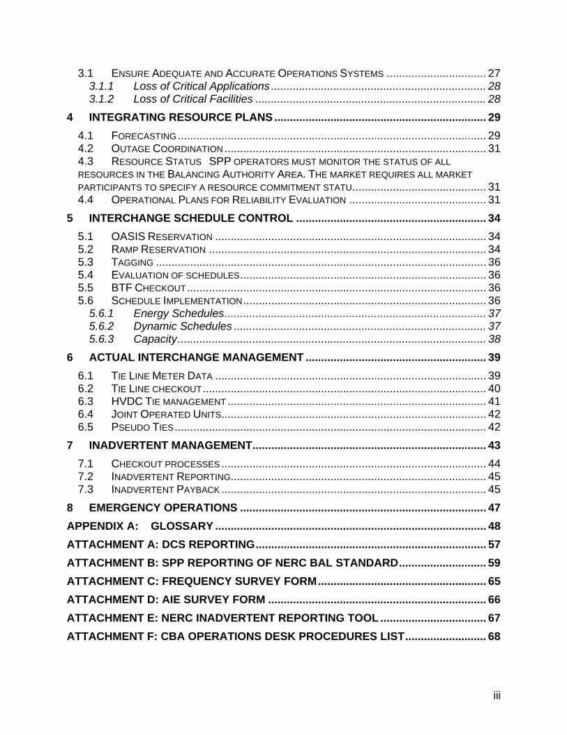
Revisions
Revision Date
Posted Date
Effective Description of Modification
1.0 6/10/2010 Initial Creation
1.0 7/15/2010 7/15/2010 Additional details and attachments
1 RESOURCE AND DEMAND BALANCING ............................................................. 1
1.1 OVERVIEW .......................................................................................................... 1 1.1.1 Generation control ..................................................................................... 1 1.1.2 Schedule Control ....................................................................................... 2 1.1.3 Load Control .............................................................................................. 2
1.2 SPP BALANCING AUTHORITY RESPONSIBILITIES .................................................... 3 1.2.1 Ahead of Time ........................................................................................... 3 1.2.2 Real Time .................................................................................................. 3 1.2.3 After the Hour ............................................................................................ 4
2 SUPPORT INTERCONNECTION FREQUENCY ..................................................... 5 2.1 AREA CONTROL ERROR ....................................................................................... 5
2.1.1 ACE Calculation ......................................................................................... 5 2.1.2 Control Performance .................................................................................. 7 2.1.3 Disturbance Control ................................................................................... 9
2.2 AUTOMATIC GENERATOR CONTROL .................................................................... 10 2.2.1 SPP EMS AGC (RTGEN) Operations ...................................................... 10 2.2.2 SPP GOP EMS AGC Operations ............................................................. 11
2.3 OPERATING RESERVES ...................................................................................... 12 2.3.1 Monitoring Reserves ................................................................................ 12 2.3.2 Regulating Reserves ............................................................................... 14 2.3.3 Contingency Reserves ............................................................................. 17 2.3.4 Qualifying Regulating Resources ............................................................. 19
2.4 TIME ERROR CORRECTIONS ............................................................................... 20 2.4.1 Time Error Correction Notification ............................................................ 20
2.5 METER ERROR CORRECTIONS ............................................................................ 21 2.5.1 Tie Line Error Determination .................................................................... 21
2.6 FREQUENCY BIAS SETTINGS .............................................................................. 23 2.6.1 Calculating Frequency Bias Setting ......................................................... 24 2.6.2 Reporting Frequency Bias Settings ......................................................... 24
3 MONITORING REAL TIME SYSTEMS ................................................................. 26
iii
3.1 ENSURE ADEQUATE AND ACCURATE OPERATIONS SYSTEMS ................................ 27 3.1.1 Loss of Critical Applications ..................................................................... 28 3.1.2 Loss of Critical Facilities .......................................................................... 28
4 INTEGRATING RESOURCE PLANS .................................................................... 29 4.1 FORECASTING ................................................................................................... 29 4.2 OUTAGE COORDINATION .................................................................................... 31 4.3 RESOURCE STATUS SPP OPERATORS MUST MONITOR THE STATUS OF ALL RESOURCES IN THE BALANCING AUTHORITY AREA. THE MARKET REQUIRES ALL MARKET PARTICIPANTS TO SPECIFY A RESOURCE COMMITMENT STATU ........................................... 31 4.4 OPERATIONAL PLANS FOR RELIABILITY EVALUATION ............................................ 31
5 INTERCHANGE SCHEDULE CONTROL ............................................................. 34 5.1 OASIS RESERVATION ....................................................................................... 34 5.2 RAMP RESERVATION ......................................................................................... 34 5.3 TAGGING .......................................................................................................... 36 5.4 EVALUATION OF SCHEDULES ............................................................................... 36 5.5 BTF CHECKOUT ................................................................................................ 36 5.6 SCHEDULE IMPLEMENTATION .............................................................................. 36
5.6.1 Energy Schedules .................................................................................... 37 5.6.2 Dynamic Schedules ................................................................................. 37 5.6.3 Capacity ................................................................................................... 38
6 ACTUAL INTERCHANGE MANAGEMENT .......................................................... 39 6.1 TIE LINE METER DATA ....................................................................................... 39 6.2 TIE LINE CHECKOUT ........................................................................................... 40 6.3 HVDC TIE MANAGEMENT ................................................................................... 41 6.4 JOINT OPERATED UNITS ..................................................................................... 42 6.5 PSEUDO TIES .................................................................................................... 42
7 INADVERTENT MANAGEMENT ........................................................................... 43 7.1 CHECKOUT PROCESSES ..................................................................................... 44 7.2 INADVERTENT REPORTING.................................................................................. 45 7.3 INADVERTENT PAYBACK ..................................................................................... 45
8 EMERGENCY OPERATIONS ............................................................................... 47 APPENDIX A: GLOSSARY ....................................................................................... 48 ATTACHMENT A: DCS REPORTING .......................................................................... 57 ATTACHMENT B: SPP REPORTING OF NERC BAL STANDARD ............................ 59 ATTACHMENT C: FREQUENCY SURVEY FORM ...................................................... 65 ATTACHMENT D: AIE SURVEY FORM ...................................................................... 66 ATTACHMENT E: NERC INADVERTENT REPORTING TOOL .................................. 67 ATTACHMENT F: CBA OPERATIONS DESK PROCEDURES LIST .......................... 68

iv

Balancing Authority Operations
Version 1.0 Page 1
1 Resource and Demand Balancing
1.1 Overview
Southwest Power Pool will obtain and maintain the necessary systems, staffing, enabling agreements, and authorizations to provide Balancing Authority services to those entities that contract with SPP for such services. Balancing Authorities are responsible for meeting the standards defined by the North American Electric Reliability Corporation (NERC) for such entities to maintain reliable operation of the bulk electric system. A Balancing Authority Area is an electrical system bounded by sufficient metering to measure interchange with other areas and capable of controlling it’s resources to match actual interchange with scheduled interchange. As part of providing Balancing Authority Services SPP will procure or contract with generation operators, load serving entities, and other contract services as required to calculate Area Control Error and provide sufficient resources/load control to maintain actual interchange to scheduled values. Specific attributes/services and provision of such are described in the following descriptions.
1.1.1 Generation control
SPP will perform generation control by entering into an agreement with those who have the ability to control generation referred to as Balancing Zones (MPs)
• SPP CBA will become the entity responsible for controlling generation and interchange in the SPP Balancing Authority Area and issue a Regulation Deployment Signal (RDS) to each MP. See also Appendix F for KCPL comments
• SPP will utilize resource plans submitted by market participants as the generation plan within the SPP area.
• SPP CBA will calculate ACE and send to each MP via ICCP, a RDS based on their share of the ACE requirement. Section 2 and Appendix A describe this process in more detail.
• The SPP Market System will calculate and send via ICCP and XML the economic base point for each resource in the SPP EI Market. This is not a change from existing operations.
• The SPP RSS will develop and send via RTO_SS a RSS schedules to the SPP BAs and MPs for each resource designated (in the event of a contingency) in RSS by the BA and MP to carry contingency reserves. SPP intends to utilize existing functionality in its market system and RSS to support this process. The
Balancing Authority Operations
Version 1.0 Page 2
MP will combine the NSI and regulation deployment signals to create a zonal SCE for the resources under its control, and will subsequently issue control signals to their resources through their respective Energy Management System or other local control mechanism
1.1.2 Schedule Control
SPP CBA will perform schedule control by entering into an agreement with existing adjacent BAs outlining SPPs authority to have control over schedules. RTO_SS is configured to give SPP the capability to act on behalf of existing BAs, and SPP CBA expects to utilize existing functionality to perform this function as a CBA. Approving schedules for Ramp Rate criteria is detailed in Task 6. The following will be performed to facilitate schedule control:
• SPP CBA is the scheduling entity and interchange authority for MPs in the CBA and other SPP BA.
• SPP will be listed as the Generation Control Area (GCA) on all schedules where energy is sourcing within the SPP BA.
• SPP will be listed as the Load Control Area (LCA) on all schedules where energy is sinking within the SPP BA.
• The LSE/GOP will be listed as POR or POD in the transmission section of a NERC tag to maintain granularity on an electrical equivalent basis. SPP will continue to utilize Source and Sink in the SPP Market Flow Calculator (MFC) and the NERC IDC for curtailment calculation purposes.
• The SPP BA will have primary approval for all schedules in the SPP BA including Coordination of DC tie tags with DC tie operator and neighboring BAs.
• PSEs, Load Serving Entities (LSEs) and GOPs will have passive approval and active denial on their tags.
• The PSE, LSE or GOP will receive all schedules affecting them and enter the schedules into their accounting system.
1.1.3 Load Control
SPP will take actions to control load utilizing the following • SPP will utilize market participant load forecasts along with existing LSE and
internally generated forecasts as input into the MOS and BA studies. • SPP will utilize the BA and existing RC authority to institute emergency operating
plans working through the MP to coordinate with TOP, GOP, LSE, should the SPP CBA impose a burden on the bulk electric system, including implementation of public appeals, etc. (Reference Section 10, Emergency Operating Plan)
Balancing Authority Operations
Version 1.0 Page 3
1.2 SPP Balancing Authority Responsibilities
1.2.1 Ahead of Time
• Receive operating and availability status of generating units and operational plans, commitments, and retirement plans from Generator Operators (including annual maintenance plans) within the SPP CBA.
• Receive reliability evaluations from the Reliability Coordinator. • Receive approved, valid, and balanced interchange schedules from the
Interchange authorities. • Compile load forecasts from Load-Serving Entities. • Develop agreements with adjacent Balancing Authorities for ACE calculation
parameters. • Submit integrated operational plans to the Reliability Coordinator for reliability
evaluation and provide balancing information to the Reliability Coordinator for monitoring.
• Confirm interchange schedules with Interchange Authorities. • Confirm ramping capability with Interchange Authorities • Coordinate generator commitment, coordinate dispatch schedules for self
dispatched resources, and implement dispatch for resources that are made available to the SPP Market from the LSE and Generator Operators who have arranged for generation within the SPP CBA.
• Acquire reliability-related services • Receive dispatch adjustments from Reliability Coordinators to prevent exceeding
SOL and IROL limits. • Receive information from Load Serving Entities on self-provided reliability-related
services. • Coordinate system restoration plans with Transmission Operator(s) and
Reliability Coordinator(s). • Provide generation dispatch to Reliability Coordinators. • Receive final approval or denial of interchange transactions from Interchange
Authority. • Develop contingency operating plans and reversion plans. • Validate the MP is listed on the e-tag in the POR/POD section to maintain
granularity for the SPP MFC and the NERC IDC.
1.2.2 Real Time
• Coordinate use of controllable loads with Load-Serving Entities (i.e., interruptible load that has been bid in as a reliability-related service).
Balancing Authority Operations
Version 1.0 Page 4
• Provide transmission losses • Receive real-time operating information from the Transmission Operator,
adjacent Balancing Authorities and Generator Operators. • Provide real-time operational information for Reliability Coordinator monitoring. • Receive reliability alerts from Reliability Coordinator. • Comply with reliability directives requirements specified by Reliability
Coordinator. • Verify implementation of emergency procedures to Reliability Coordinator and
other entities as appropriate. • Inform Reliability Coordinator and Interchange Authorities of interchange
schedule interruptions (e.g., due to generation or load interruptions) within its Balancing Authority Area.
• Coordinate with MP to take actions required to ensure balance in real time. • Coordinate with MP to reduce voltage or shed load if needed to ensure balance
within its Balancing Authority Area. • Coordinate with TO’s and direct other generator operators, if necessary, to
implement redispatch for congestion management as directed by the Reliability Coordinator.
• Implement corrective actions and emergency procedures as directed by the Reliability Coordinator.
• Receive information of interchange schedule curtailments from Interchange Authority.
1.2.3 After the Hour
• Confirm Scheduled interchange with Interchange Authorities BTF and after the hour for “checkout.”
Balancing Authority Operations
Version 1.0 Page 5
2 SUPPORT INTERCONNECTION FREQUENCY
2.1 Area Control Error
2.1.1 ACE Calculation The calculation of Area Control Error (ACE) is given the formula ACE = (NIA – NIS) – 10B (FA – FS) - IME To calculate ACE SPP needs to obtain the information necessary to compute and/or verify the following information:
• Actual Net Interchange – NIA – the algebraic sum of actual flows on all tie lines • Scheduled Net Interchange – NIS – the algebraic sum of scheduled flows on all
tie lines • Actual Frequency – FA • Scheduled Frequency - FS • Calculated Frequency Bias – B is the Frequency bias setting (MW/0.1 Hz) for all
BA. The constant factor of 10 converts the frequency setting to MW/HZ • Meter Error IME - IME – meter error correction factor
Area Control Error is a measure of the imbalance between sources of power and uses of power within the SPP CBA. This imbalance is calculated indirectly as the difference between scheduled and actual net interchange, plus the frequency bias contribution to yield ACE in megawatts. Two additional terms may be included in ACE under certain conditions--the time error bias term and SPP operator adjustment term (manual add). These provide for automatic inadvertent interchange payback and error compensation, respectively. The SPP Energy Management ACE calculation includes the following:
• NERC sign conventions when sending and receiving to/from MPs. is calculated and sent and resultant dispatch signal are sent on a 4 second basis via ICCP
• SPP use the OGE Robinson Bus as the backup frequency point for ACE SPP will use an AEP/PSO point as an alternate backup frequency point for ACE
• ACE calculation parameters are such that on a rolling 12-month basis, the average of the clock-minute averages of the Balancing Authority’s Area Control
Balancing Authority Operations
Version 1.0 Page 6
Error (ACE) divided by 10B (B is the clock-minute average of the Balancing Authority Area’s Frequency Bias) times the corresponding clock-minute averages of the Interconnection’s Frequency Error is less than a specific limit. This limit is a constant derived from a targeted frequency bound (separately calculated for each Interconnection) that is reviewed and set as necessary by the NERC Operating Committee.
• ACE calculation parameters are such that SPP’s average ACE for at least 90%
of clock-ten-minute periods (6 non-overlapping periods per hour) during a calendar month is within a ___ referred to as L10.
• Data acquisition for the calculation of the SPP BAA ACE occur at least every six
seconds.
• SPP provides redundant and independent frequency metering equipment that automatically activates upon detection of failure of the primary source. This overall installation provides a minimum availability of 99.95%.
• All Interchange Schedules with Adjacent Balancing Authorities are included in the
calculation of Net Scheduled Interchange for the SPP ACE BAA equation.
• Interchange Schedule related to the HVDC link from the ACE equation are omitted or included to match how they are modeled as internal generation or load.
• All Dynamic Schedules are included in the calculation of Net Scheduled
Interchange for the SPP BAA ACE equation.
• The effect of Ramp rates are included in the Scheduled Interchange values to calculate SPP BAA ACE.
• All Tie Line flows with Adjacent Balancing Authority Areas are included in the
SPP BAA ACE calculation.
• Ensure Tie Line MW metering is telemetered to both control centers, and emanates from a common, agreed-upon source using common primary metering equipment.
2.1.1.1 SPP operator actions: SPP operator monitors the SPP Balancing Authority ACE equations SPP operator makes adjustments as needed per procedures SPP operator coordinates
Balancing Authority Operations
Version 1.0 Page 7
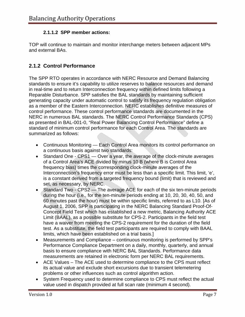
2.1.1.2 SPP member actions: TOP will continue to maintain and monitor interchange meters between adjacent MPs and external BAs.
2.1.2 Control Performance
The SPP RTO operates in accordance with NERC Resource and Demand Balancing standards to ensure it’s capability to utilize reserves to balance resources and demand in real-time and to return Interconnection frequency within defined limits following a Reparable Disturbance. SPP satisfies the BAL standards by maintaining sufficient generating capacity under automatic control to satisfy its frequency regulation obligation as a member of the Eastern Interconnection. NERC establishes definitive measures of control performance. These control performance standards are documented in the NERC in numerous BAL standards. The NERC Control Performance Standards (CPS) as presented in BAL-001-0, “Real Power Balancing Control Performance” define a standard of minimum control performance for each Control Area. The standards are summarized as follows:
• Continuous Monitoring — Each Control Area monitors its control performance on a continuous basis against two standards:
• Standard One - CPS1 — Over a year, the average of the clock-minute averages of a Control Area’s ACE divided by minus 10 B (where B is Control Area frequency bias) times the corresponding clock-minute averages of the Interconnection’s frequency error must be less than a specific limit. This limit, ‘e’, is a constant derived from a targeted frequency bound (limit) that is reviewed and set, as necessary, by NERC.
• Standard Two - CPS2 — The average ACE for each of the six ten-minute periods during the hour (i.e., for the ten-minute periods ending at 10, 20, 30, 40, 50, and 60 minutes past the hour) must be within specific limits, referred to as L10. [As of August 1, 2006, SPP is participating in the NERC Balancing Standard Proof-Of-Concept Field Test which has established a new metric, Balancing Authority ACE Limit (BAAL), as a possible substitute for CPS-2. Participants in the field test have a waiver from meeting the CPS-2 requirement for the duration of the field test. As a substitute, the field test participants are required to comply with BAAL limits, which have been established on a trial basis.]
• Measurements and Compliance – continuous monitoring is performed by SPP’s Performance Compliance Department on a daily, monthly, quarterly, and annual basis to ensure compliance with NERC BAL Standards. Performance data measurements are retained in electronic form per NERC BAL requirements.
• ACE Values – The ACE used to determine compliance to the CPS must reflect its actual value and exclude short excursions due to transient telemetering problems or other influences such as control algorithm action.
• System Frequency used to determine compliance to CPS must reflect the actual value used in dispatch provided at full scan rate (minimum 4 second).
Balancing Authority Operations
Version 1.0 Page 8
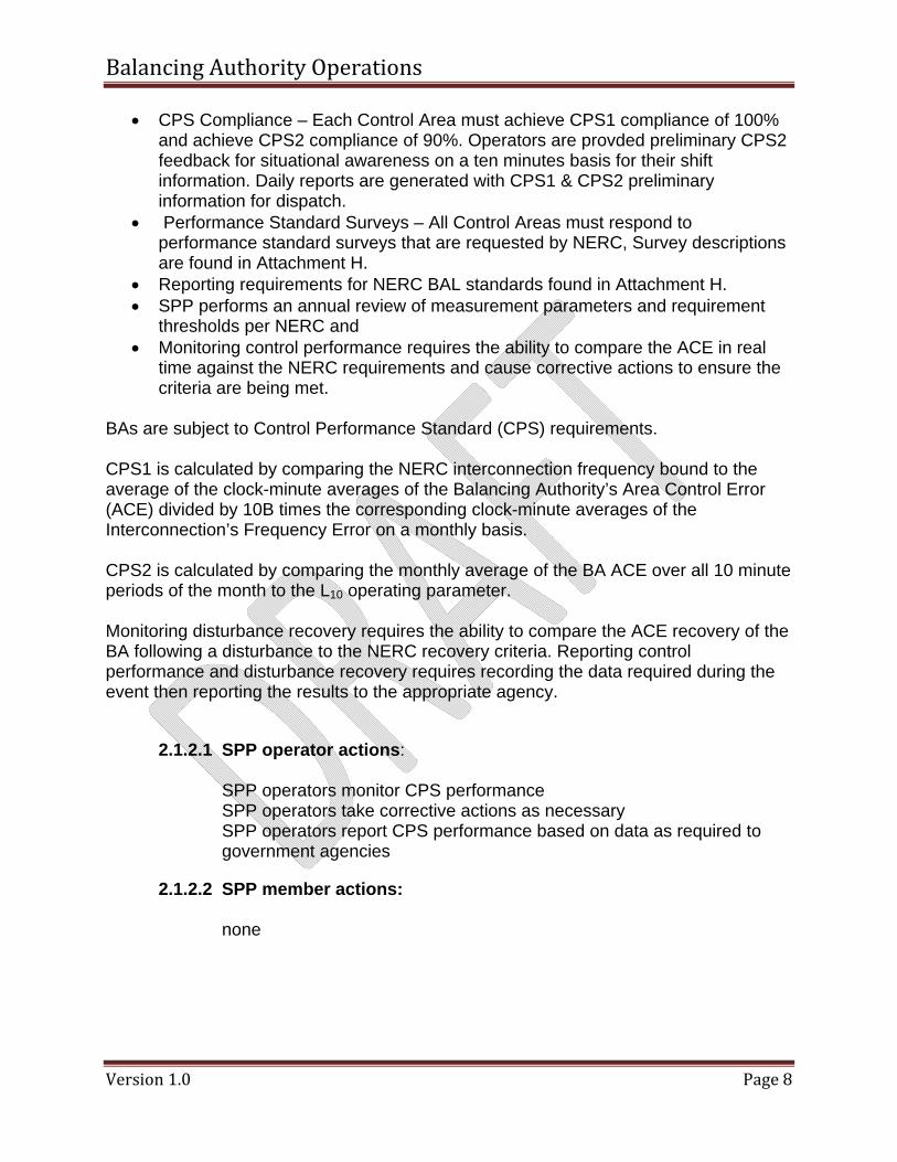
• CPS Compliance – Each Control Area must achieve CPS1 compliance of 100% and achieve CPS2 compliance of 90%. Operators are provded preliminary CPS2 feedback for situational awareness on a ten minutes basis for their shift information. Daily reports are generated with CPS1 & CPS2 preliminary information for dispatch.
• Performance Standard Surveys – All Control Areas must respond to performance standard surveys that are requested by NERC, Survey descriptions are found in Attachment H.
• Reporting requirements for NERC BAL standards found in Attachment H. • SPP performs an annual review of measurement parameters and requirement
thresholds per NERC and • Monitoring control performance requires the ability to compare the ACE in real
time against the NERC requirements and cause corrective actions to ensure the criteria are being met.
BAs are subject to Control Performance Standard (CPS) requirements. CPS1 is calculated by comparing the NERC interconnection frequency bound to the average of the clock-minute averages of the Balancing Authority’s Area Control Error (ACE) divided by 10B times the corresponding clock-minute averages of the Interconnection’s Frequency Error on a monthly basis. CPS2 is calculated by comparing the monthly average of the BA ACE over all 10 minute periods of the month to the L10 operating parameter. Monitoring disturbance recovery requires the ability to compare the ACE recovery of the BA following a disturbance to the NERC recovery criteria. Reporting control performance and disturbance recovery requires recording the data required during the event then reporting the results to the appropriate agency.
2.1.2.1 SPP operator actions: SPP operators monitor CPS performance SPP operators take corrective actions as necessary SPP operators report CPS performance based on data as required to government agencies
2.1.2.2 SPP member actions: none
Balancing Authority Operations
Version 1.0 Page 9
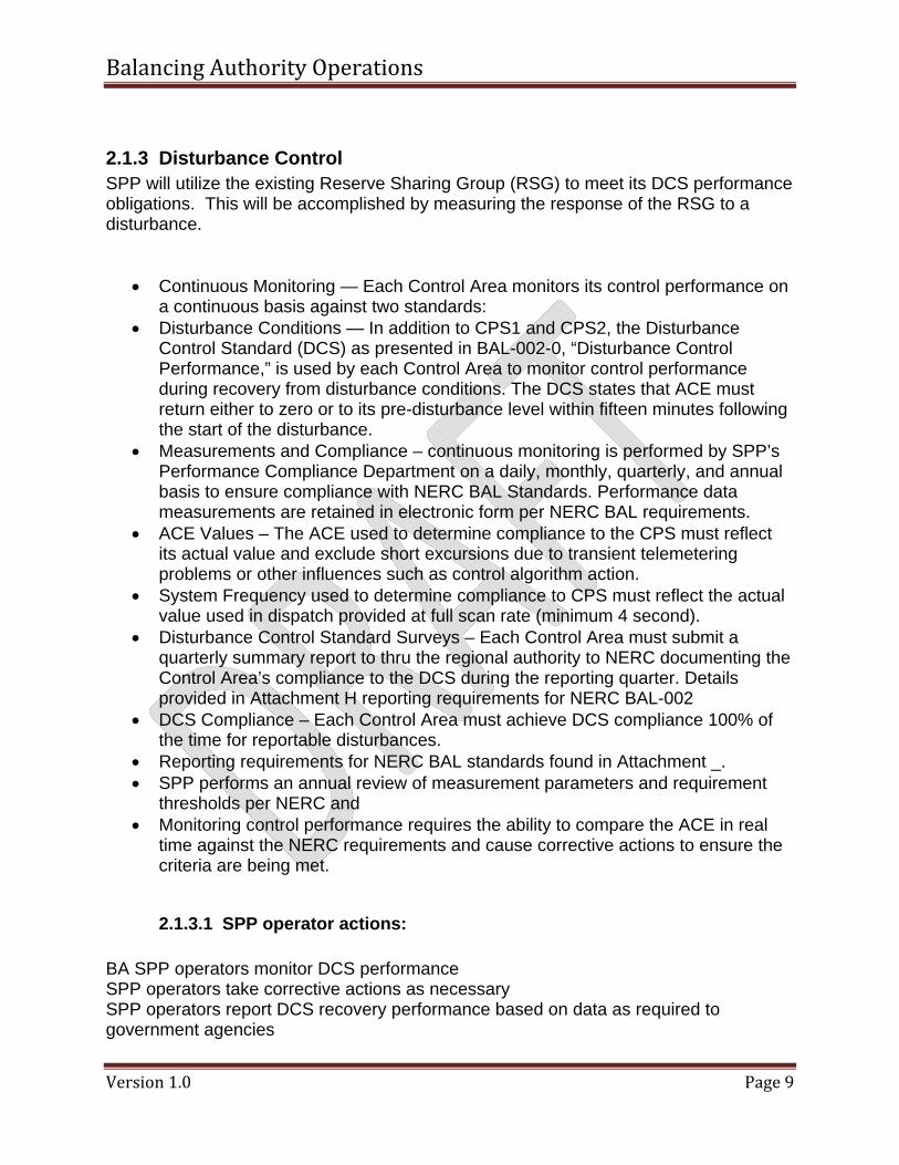
2.1.3 Disturbance Control SPP will utilize the existing Reserve Sharing Group (RSG) to meet its DCS performance obligations. This will be accomplished by measuring the response of the RSG to a disturbance.
• Continuous Monitoring — Each Control Area monitors its control performance on a continuous basis against two standards:
• Disturbance Conditions — In addition to CPS1 and CPS2, the Disturbance Control Standard (DCS) as presented in BAL-002-0, “Disturbance Control Performance,” is used by each Control Area to monitor control performance during recovery from disturbance conditions. The DCS states that ACE must return either to zero or to its pre-disturbance level within fifteen minutes following the start of the disturbance.
• Measurements and Compliance – continuous monitoring is performed by SPP’s Performance Compliance Department on a daily, monthly, quarterly, and annual basis to ensure compliance with NERC BAL Standards. Performance data measurements are retained in electronic form per NERC BAL requirements.
• ACE Values – The ACE used to determine compliance to the CPS must reflect its actual value and exclude short excursions due to transient telemetering problems or other influences such as control algorithm action.
• System Frequency used to determine compliance to CPS must reflect the actual value used in dispatch provided at full scan rate (minimum 4 second).
• Disturbance Control Standard Surveys – Each Control Area must submit a quarterly summary report to thru the regional authority to NERC documenting the Control Area’s compliance to the DCS during the reporting quarter. Details provided in Attachment H reporting requirements for NERC BAL-002
• DCS Compliance – Each Control Area must achieve DCS compliance 100% of the time for reportable disturbances.
• Reporting requirements for NERC BAL standards found in Attachment _. • SPP performs an annual review of measurement parameters and requirement
thresholds per NERC and • Monitoring control performance requires the ability to compare the ACE in real
time against the NERC requirements and cause corrective actions to ensure the criteria are being met.
2.1.3.1 SPP operator actions: BA SPP operators monitor DCS performance SPP operators take corrective actions as necessary SPP operators report DCS recovery performance based on data as required to government agencies
Balancing Authority Operations
Version 1.0 Page 10
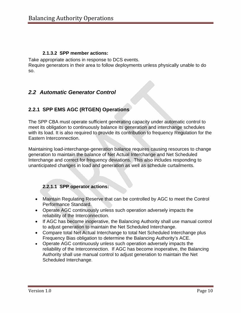
2.1.3.2 SPP member actions: Take appropriate actions in response to DCS events. Require generators in their area to follow deployments unless physically unable to do so.
2.2 Automatic Generator Control
2.2.1 SPP EMS AGC (RTGEN) Operations The SPP CBA must operate sufficient generating capacity under automatic control to meet its obligation to continuously balance its generation and interchange schedules with its load. It is also required to provide its contribution to frequency Regulation for the Eastern Interconnection. Maintaining load-interchange-generation balance requires causing resources to change generation to maintain the balance of Net Actual Interchange and Net Scheduled Interchange and correct for frequency deviations. This also includes responding to unanticipated changes in load and generation as well as schedule curtailments.
2.2.1.1 SPP operator actions:
• Maintain Regulating Reserve that can be controlled by AGC to meet the Control Performance Standard.
• Operate AGC continuously unless such operation adversely impacts the reliability of the Interconnection.
• If AGC has become inoperative, the Balancing Authority shall use manual control to adjust generation to maintain the Net Scheduled Interchange.
• Compare total Net Actual Interchange to total Net Scheduled Interchange plus Frequency Bias obligation to determine the Balancing Authority’s ACE.
• Operate AGC continuously unless such operation adversely impacts the reliability of the Interconnection. If AGC has become inoperative, the Balancing Authority shall use manual control to adjust generation to maintain the Net Scheduled Interchange.
Balancing Authority Operations
Version 1.0 Page 11
2.2.1.2 SPP member actions: • TOP will continue to maintain metered tie line boundaries for instantaneous and
hourly meter data with each adjacent MP and SPP CBA. • Provide infrastructure to allow resources in the GOP to be controlled from the
their AGC. • GOP will provide information to SPP CBA regarding units that are on AGC or
manual control • Balance local load and generation to meet RDS signal/schedule
2.2.2 SPP GOP EMS AGC Operations
The GOP will ultimately maintain balance by sending a base point to each resource that is the net of the economic base point, the real time regulation deployment and contingency reserve assistance deployment signal to match load and generation inside the CBA and support interconnection frequency.
• Economic base point from EIS Market • Real time regulation deployment based on SPP CBA ACE • Reserve Sharing Spinning and Supplemental schedule from RSS.
Also, the CBA must have appropriate metering and be able to monitor transmission system loading in real time as well as a monitoring and alarming system to give the CBA, in coordination with the TOP, an indication of problems in real time for normal and emergency conditions.
2.2.2.1 SPP operator actions:
SPP will send the SCE and a RDS to each MP via ICCP to be used to control generation for regulation of ACE.
2.2.2.2 SPP member actions: GOP receives dispatch signals GOP allocates dispatch signals to appropriate resources GOP provides information to SPP CBA regarding units that are on AGC or manual control GOP and TOP balance local load and generation to meet RDS signal/schedule
• Operate AGC continuously unless such operation adversely impacts the reliability of the Interconnection. If AGC has become inoperative, the Balancing Authority shall use manual control to adjust generation to maintain the Net Scheduled Interchange.
Balancing Authority Operations
Version 1.0 Page 12
2.3 Operating Reserves
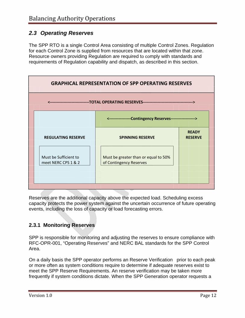
The SPP RTO is a single Control Area consisting of multiple Control Zones. Regulation for each Control Zone is supplied from resources that are located within that zone. Resource owners providing Regulation are required to comply with standards and requirements of Regulation capability and dispatch, as described in this section.
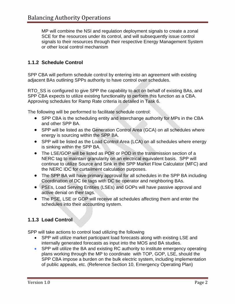
GRAPHICAL REPRESENTATION OF SPP OPERATING RESERVES
<‐‐‐‐‐‐‐‐‐‐‐‐‐‐‐‐‐‐‐‐‐‐‐‐‐‐‐‐‐TOTAL OPERATING RESERVES‐‐‐‐‐‐‐‐‐‐‐‐‐‐‐‐‐‐‐‐‐‐‐‐‐‐‐‐‐‐‐‐‐‐‐‐‐>
<‐‐‐‐‐‐‐‐‐‐‐‐‐‐‐‐Contingency Reserves‐‐‐‐‐‐‐‐‐‐‐‐‐‐‐‐‐‐>
REGULATING RESERVE SPINNING RESERVE READY RESERVE
Must be Sufficient to meet NERC CPS 1 & 2
Must be greater than or equal to 50% of Contingency Reserves
Reserves are the additional capacity above the expected load. Scheduling excess capacity protects the power system against the uncertain occurrence of future operating events, including the loss of capacity or load forecasting errors.
2.3.1 Monitoring Reserves SPP is responsible for monitoring and adjusting the reserves to ensure compliance with RFC-OPR-001, “Operating Reserves” and NERC BAL standards for the SPP Control Area. On a daily basis the SPP operator performs an Reserve Verification prior to each peak or more often as system conditions require to determine if adequate reserves exist to meet the SPP Reserve Requirements. An reserve verification may be taken more frequently if system conditions dictate. When the SPP Generation operator requests a
Balancing Authority Operations
Version 1.0 Page 13
reserve verification, member operators report the information via EMS. If is unavailable, member operators report the information directly to the SPP Generation operator. An Reserve Verification provides SPP operator with an indication of the actual reserves that are available at that point in time. By conducting the verification at strategic points during the day, SPP operator establishes benchmarks between which the actual reserve can be estimated. Since system conditions can change very rapidly, This is only an indication of the actual reported reserves at that point in time. SPP operator uses the results to determine if reserve shortages exist and what, if any, Emergency procedures should be declared to supplement the electronic reporting of reserves through the EMS systems. When the SPP Net Tie Deviation indicates under-generation, the Synchronized Reserve total is adjusted downward by the amount of the Net Tie Deviation to reflect the SPP Control Area’s generation deficiency. Conversely, when the SPP Net Tie Deviation indicates over-generation, the Synchronized Reserve total is adjusted upward by the amount of the Net Tie Deviation to reflect the SPP Control Area’s generation excess. Therefore, when possible SPP operator requests an reserve verification when the ACE and Net Tie Deviation is close to zero MW.
2.3.1.1 SPP Actions:
1. Using the SPP satphone, SPP operator requests an Reserve Verifciation. 2. Upon receipt of all Generation Owner reports, SPP operator determines the
following values: ____________ 3. SPP operator compares the values calculated in Step (2) to the corresponding
objectives and then determines whether reserve deficiencies exist. 4. Using the SPP EMS, SPP operator reports the results of the verification tothe
Generation Owners/Transmission Owners.
2.3.1.2 SPP Member Actions: The Generation Owner operators promptly report the following values to SPP via. If the EMS is unavailable, the values are reported directly to SPP operator via telephone:
• Normal Regulating Reserve • Spinning Reserve Non-Regulating • Normal Regulating Reserve • Spinning Reserve Non-Regulating • Spinning Reserve Regulating • Quick Start Reserves • Secondary Reserve • Operating Reserve • Scheduled capability that is more that 30 minutes away • Capacity reductions that are not known to SPP operator
Balancing Authority Operations
Version 1.0 Page 14
• See Attachment A for reserve calculations and IRC reporting requirements.
2.3.2 Regulating Reserves The Regulation Requirement for the SPP RTO is 1.0% of the forecast peak load for the entire day. There is no distinction between On-Peak Periods and Off-Peak Periods. The resources assigned to meet this requirement must be capable of responding to the AR signal immediately, achieve their bid capability within five minutes and must increase or decrease their outputs at the ramping rates that are specified in the data that is submitted to SPP. The SPP RTO requires that the Regulation range of a resource is at least twice the amount of Regulation assigned. A resource capable of automatic energy dispatch that is also providing Regulation reduces its energy dispatch range by the regulation assigned to the resource. This redefines the energy dispatch range of that resource. (The resource’s assigned regulation subtracted from its regulation maximum forms the upper limit of the new dispatch range, while the resource’s regulation minimum plus its assigned regulation forms the lower limit of the new dispatch range.) Assigned Regulation is the assigned hourly regulation quantity (MW) that is cleared from the regulation market system. It is assigned for each individual resource that is qualified to regulate in the SPP market. This value, although typically static for the hour, will be sent on a 10 second scan rate. Real-time instantaneous resource owner fleet regulation signal (+/- MW). This signal is used to move regulating resources in the owner’s fleet within the fleet capability (+/- TReg). This value will be sent on a 2 second scan rate. Total Regulation is the real-time fleet regulation capability (MW) that represents the active resource owner’s ability to regulate. Ideally the value of this quantity should be the sum of the resource owner’s non-zero AReg quantities for the majority of the hour, but must reflect any reductions in regulating capability as they occur (unit LFC limit restrictions, resource “off control” conditions, etc.). This value shall be calculated every 2 seconds and sent on a 2-second scan rate. Current Regulation is the real-time fleet regulation feedback (+/- MW) that epresents the active position of the fleet with respect to the +/- TReg capability. Ideally the value of this quantity will track the RegA signal if the regulating fleet is responding as prescribed. This value shall be calculated every 2 seconds and sent on a 2-second scan rate.
2.3.2.1 Determining Regulation Assignment The SPP RTO’s Regulating Requirement is a function of the day’s load forecast, as determined by the SPP operator. Each LSE is required to provide a share of the SPP
Balancing Authority Operations
Version 1.0 Page 15
Regulating Requirement. An LSE’s actual hourly Regulation obligation is determined for the hour, after-the-fact, based on the LSE’s total load in the SPP RTO, as follows:
2.3.2.1.1 SPP Operator Actions: Prior to the beginning of each day, SPP operator determines the SPP RTO At 2230, SPP provides the following information to the Transmission Owners/Generation Owners for the LSE's, via the SPP --- SPP RTO Regulation Requirement for the following day.
2.3.2.1.2 SPP Members Actions: Each LSE determines its estimated Regulation Obligation for the operating day based on its own forecast load and the information received via the SPP -- Resource owners view the hourly regulation market results via market (available at least a half an hour before the operating hour) as to those resources to which regulation has been assigned. Resource owners that have self-scheduled Regulation on any of their resources inform the SPP operator when those resources are on line and able to provide the self-scheduled Regulation. Once regulation on a resource is self-scheduled by a resource owner, it is no longer eligible to participate as a pool assigned regulating resource for the current operating day. If purchasing Regulation from another entity, the buyer and seller negotiate the transaction and the buyer submits the transaction through the Regulation Bilateral page of the market The seller must then confirm the transaction via the market by 4:00pm the day after the operating day. The rules for these transactions are described in more detail later in this section of the manual.
2.3.2.2 Dispatching Regulation SPP obtains the most cost efficient Regulation Ancillary Service available, as needed, to meet the SPP RTO’s Regulation Requirement. SPP assigns Regulation in economic order based on the total cost of each available resource to provide Regulation, including real time opportunity cost and the resource’s Regulation offer price. The AR signals are then automatically sent to the Resource Owners. Resource Owners are responsible for maintaining unit regulating capability. Exhibit 9 shows how the Regulation is assigned to the resources. ???? signals that are transmitted by SPP. Market Sellers must operate their regulating resources as close to desired output levels, as practical, consistent with Good Utility Practices.
Balancing Authority Operations
Version 1.0 Page 16
2.3.2.3 Regulation Deficiency After the initial Regulation assignments are made, and throughout the operating hour, SPP Members report changes to their resource’s regulating capabilities either by a phone call to SPP or by virtue of the regulation signal each company sends to SPP. If a resource becomes unable to supply its assigned amount of Regulation, the SPP operator must de-assign deficient resources and assign replacement Regulation to ensure that the total Regulation requirement is met. Such assignments are made economically based on each available resource’s total cost to provide regulation, including real time opportunity cost and the resource’s regulation offer price. If, after assigning all available Regulation, the SPP Regulating Requirement is still not met, SPP operator operates the system without the required amount of Regulation, logging such events. In the event there is a loss of EMS communication between SPP and a resource owner, Current Regulation Assignments must be reassigned to another Resource Owner until EMS communication is reestablished.
2.3.2.4 Regulation Excess If during the period an excess in assigned Regulation occurs and the total SPP RTO Regulation value exceeds the objectives by __ MW or more, SPP operator de-assigns Regulation economically based on each resource’s total cost to provide regulation, including real time opportunity cost and the resource’s regulation offer price.
2.3.2.4.1 SPP Actions: SPP operator continuously monitors the Regulation deviation to assess Resource Owner fleet capability and reassigns Regulation as required.
2.3.2.4.2 SPP Member Actions: When initial assignments and reassignments are made, each affected Resource Owner operator then updates the entity’s regulating capability as defined by the _____________ . Bilateral Transactions
Balancing Authority Operations
Version 1.0 Page 17
One SPP Member may sell Regulation Ancillary Service to another SPP Member. The two members must agree on the MW amount of capability being sold, schedule Regulation accordingly, and submit the two-SPP Member Regulation transaction to SPP via ancillary services market . All two-SPP Member transfers of regulating capability must be submitted as MW amounts via the market. The two members agree on the amount and duration of the Regulation transaction prior to the sale.
• The “buying” member submits the MW amount of the two-SPP Member transaction, the selling member, and the start and end time of the transaction via the market
• The “selling” member confirms the transaction via the market by 4:00pm the day after the operating day. .
2.3.3 Contingency Reserves Reserves are the additional capacity above the expected load. Scheduling excess capacity protects the power system against the uncertain occurrence of future operating events, including the loss of capacity or load forecasting errors. SPP CBA is responsible for monitoring and adjusting the reserves to ensure compliance with NERC BAL standards. The SPP CBA monitors the deployment of Contingency Reserves due to loss of generation and other extreme conditions. In addition SPP CBA may manually direct generation movement should the SPP CBA experience an unexpected substantial loss of load using emergency manual deployment procedures already in place. SPP CBA is a member of a Reserve Sharing Group and allocate contingency reserve requirements based on Criteria 6.
2.3.3.1 SPP operator Actions: • Activate sufficient Contingency Reserve to comply with the DCS.
• Carry at least enough Contingency Reserve to cover the most severe single
contingency. All Balancing Authorities and Reserve Sharing Groups shall review, no less frequently than annually, their probable contingencies to determine their prospective most severe single contingencies.
Balancing Authority Operations
Version 1.0 Page 18
• Return ACE to zero if its ACE just prior to the Reportable Disturbance was positive or equal to zero. For negative initial ACE values just prior to the Disturbance, the Balancing Authority shall return ACE to its pre-Disturbance value.
• Have access to and/or operate Contingency Reserve to respond to Disturbances. Contingency Reserve may be supplied from generation, controllable load resources, or coordinated adjustments to Interchange Schedules.
• Fulfill its Contingency Reserve obligations by participating as a member of a Reserve
Sharing Group. In such cases, the Reserve Sharing Group shall have the same responsibilities and obligations as each Balancing Authority with respect to monitoring and meeting
2.3.3.2 Restoring Reserves By continuously monitoring reserves, SPP operator ensures that reserve levels are maintained in accordance with NERC BAL Standards. During normal operation, SPP operator loads the system based on economy while monitoring the available reserves. f, however, based on the best judgment of SPP operator after evaluating the results of the IRC, reserve deficiencies exist on the system, the following actions are taken, dependent on the deficiency: Operating Reserve Deficiency — When SPP operator is assured that both the Synchronized and Primary Reserve objectives are covered, SPP operator attempts to eliminate any deficiency in Operating Reserve. Sufficient reserve is maintained for coverage of load-forecast uncertainty and probable additional failure or malfunction of generating equipment. The decision of whether to replenish Operating Reserve is based on SPP operator’s best judgment. SPP operator may choose to replenish all, some, or none of the Operating Reserve during the operating day. The default Disturbance Recovery Period is 15 minutes after the start of a Reportable Disturbance. This period may be adjusted to better suit the needs of an Interconnection based on analysis approved by the NERC Operating Committee. Fully restore its Contingency Reserves within the Contingency Reserve Restoration Period for its Interconnection. The Contingency Reserve Restoration Period begins at the end of the Disturbance Recovery Period. The default Contingency Reserve Restoration Period is 90 minutes. This period may be adjusted to better suit the reliability targets of the Interconnection based on analysis approved by the NERC Operating Committee.
Balancing Authority Operations
Version 1.0 Page 19
2.3.3.3 SPP Actions: Respond to requests for assistance due to a contingency event, as requested by another member, by scheduling delivery of assistance schedules
2.3.4 Qualifying Regulating Resources In order to ensure the quality of Regulation supplied to control the SPP RTO, a quality standard is developed. A resource must meet the quality standard to be permitted to regulate. In general, there are two phases to qualifying a regulating resource: • Certifying the resource • Verifying regulating capability An Area Regulation (AR) test is used for both certifying and verifying regulating capability for a resource. Note: It must be emphasized that the Regulation test is not intended to test a resource’s governor response to power system frequency changes. The AR test is run during a continuous 40-minute period when, in the judgment of SPP test administrator, economic or other conditions do not otherwise change the base loading of the resources that are being tested. Changes in base loading for a resource during the test period invalidate the test for that resource. Once an AR test is announced, a Resource Owner is not permitted to change any resource’s Regulation assignment. Scoring the AR test is based on compliance to two calculations: Rate of Response Compliance — The rate of response compliance is a measure of a resource’s ability to achieve its Regulation assignment within five minutes. Regulation Mismatch Compliance — The Regulation mismatch compliance is a measure of a resource’s ability to maintain its actual loading at a constant desired level for five minutes.
Balancing Authority Operations
Version 1.0 Page 20
2.4 Time Error Corrections
The system-wide mismatch between load and generation results in frequency deviations from scheduled frequency. The integrated deviation appears as a departure from correct time, i.e., as a time error. Therefore, time error is the accumulation of frequency deviation over a defined period of time. In accordance with NERC BAL Standards, each Interconnection designates an Interconnection Monitor to monitor time error and to initiate or terminate corrective action when time error reaches predetermined limits. The SPP CBA is a part of the Eastern Interconnection. The Interconnection Monitor for the Eastern Interconnection is Midwest ISO in Carmel, IN. The Midwest ISO monitors the electric system time against true time, as measured by the National Institute of Standards and Technology (NIST), in Boulder, Colorado. When time error reaches ±10 seconds, The Midwest ISO initiates a time correction. No time error corrections for fast time will be initiated between 0400 and 1100 hours Central Prevailing Time. In response to the Interconnection Monitor, SPP implements the requested frequency schedule offset. A time correction may be halted, terminated, or extended if the designated Interconnection Time Monitor or SPP determines system reliability conditions warrant such action. After the premature termination of a manual time correction, a slow time correction can be reinstated after the frequency has returned to 60 Hz or above for a period of ten minutes. A fast time correction can be reinitiated after the frequency has returned to 60 Hz or lower for a period of ten minutes. At least 1 hour shall elapse, however, between the termination and re-initiation notices.
2.4.1 Time Error Correction Notification The Midwest ISO issues the time correction information via a NERC hot-line conference call and a message is posted on the RCIS. A frequency offset of ±0.02 Hz starts and terminates on the hour or half-hour.
2.4.1.1 SPP Operator Actions:
• SPP operator notifies TOP/GOP, via the SPP Satephone, to announce that time error correction is in effect. To correct for a slow or fast clock, system frequency schedules are offset by ±0.02 Hz and given an assigned letter designator.
• At the assigned time, SPP operator inputs frequency schedule into the SPP EMS System using to 59.98 Hz to correct for fast time error or 60.02 Hz to correct for slow time error as directed by the time monitor. When the time error is reduced to specified levels or if the time error is not corrected in a reasonable period, the Midwest ISO issues the order to return frequency schedule setters to 60.00 Hz.
Balancing Authority Operations
Version 1.0 Page 21
The Midwest ISO initiates a NERC hot-line conference call and posts a message on the RCIS. At this time, the SPP operator resets the SPP EMS frequency schedule to 60.00 Hz at the assigned time.
• SPP operator notifies the TOP/GOP via the SPP Satephone of the cancellation of the time correction, and the time the scheduled system frequency will return to 60.00 Hz.
• If reliability concerns develop during the execution of the time error correction, the SPP operator notifies Midwest ISO (St. Paul, MN) and requests that the time error correction be immediately terminated. Similarly, if reliability concerns are anticipated with a scheduled time error correction, the SPP operator notifies Midwest ISO to cancel the scheduled time error correction.
2.4.1.2 SPP member Actions:
• If a reliability concern develops during the execution of the time error correction, the TOP/GOP shall notify the SPP operator.
SPP operations shall annually check and calibrate its time error and frequency devices against a common reference (_______) and adhere to the minimum values for measuring devices as listed below:
2.5 Meter Error Corrections
Meter Error Corrections Ensure Tie Line MW metering is telemetered to both control centers, and emanates from a common, agreed-upon source using common primary metering equipment. Balancing Authorities shall ensure that megawatt-hour data is telemetered or reported at the end of each hour. The SPP EMS receives all tie line data including pseudo ties and dynamically scheduled real-time flows to SPP via ICCP from the TOP
IME Interchange Meter Error (Investigation of existing methods required) SPP will calculate a BA Interchange meter error by comparing the accumulated real time interchange received from the TOP via ICCP with the hourly meter data received from the TOP via XML. The SPP CBA operator will enter a Meter Error correction offset when there is a significant unexplained difference between the real time and hourly metered data.
2.5.1 Tie Line Error Determination The SPP EMS receives all tie line data including pseudo ties and dynamically scheduled real-time flows to SPP via ICCP from the TOP.SPP BA operators monitor all
Balancing Authority Operations
Version 1.0 Page 22
BA to BA tie lines. SPP RTOSS receive hourly meter accumulations in MWH via ICCP promptly after the end of each clock hour from the TOP. SPP BA operators perform hourly error checks using Tie Line megawatt-hour meters with common time synchronization to determine the accuracy of its control equipment. The SPP Balancing Authority Operator monitors and determines the cause or causes of Tie Line Error and implements corrective actions in real time. The causes of Tie Line Error include, but are not limited to, the following:
• Bad telemetry • Meter failure • Unit Trips • Etc.
2.5.1.1 SPP operator actions:
Bad Telemetry – in the case of bad telemetry data, the BA operator identifies which tie lines(s) are affected via the tie line monitoring displays and the SPP EMS RTGEN.
1. The BA operator instructs the RGD to contact the associated TOP to determine the cause of the bad telemetry and appropriate values to be utilized for the affected tie lines. The BA operator then manually overrides any and all identified tie line value(s) within the SPP Balancing Authority Area (display).
2. If the tie lines are still suspect after approximately 5 minutes, the BA operator shall 3. The BA operator 4. When the telemetry issues are resolved, the BA operator will remove all manually
replaced values. 5. BA operator records all manual overrides and telemetry issues in the operator log.
IME – adjust the component (e.g., tie line meter) of ACE that is in error (if known) or use the interchange meter error (IME) term of the ACE equation to compensate for any equipment error until repairs can be made.
2.5.1.2 SPP member actions
SPP TOP continuously monitor TOP/TOP tie lines inside SPP CBA footprint TOP send all tie line data including pseudo ties and dynamically scheduled real-time flows to SPP via ICCP. TOP send the actual interchange meter MWH and manually read meter data to the SPP CBA via XML The SPP CBA is required to provide its contribution to frequency Regulation for the Eastern Interconnection.
Balancing Authority Operations
Version 1.0 Page 23
Frequency deviates from schedule because actual tie line power flow does not continuously match scheduled tie line power flow. This imbalance must be minimized, so as not to impose the SPP CBA’s control requirements on the interconnected system. Area Control Error (ACE) is a value that defines how well the SPP CBA is meeting its obligation.
2.6 Frequency Bias Settings The SPP BA is obligated to compute a frequency bias component of ACE in order to ensure that the ACE calculation supports frequency error correction for the Eastern Interconnection. SPP operators monitor the system frequency in real time and incorporate it into the ACE calculation and operate the SPP EMS on tie-line bias under normal conditions. SPP operators use a frequency bias setting that is appropriate for the frequency response characteristic of the SPP Balancing Authority Area.
10B Frequency Bias for Balancing Authority SPP will calculate a Frequency Bias for the BA
• Initial Frequency Bias The Initial Frequency Bias will be 1% of the sum of the SPP CBA Coincident Peak Load obligation. (BAL-003-0 R5)
• Subsequent Frequency Bias Subsequent Frequency Bias will be calculated as the higher of 1% of the SPP CBA Coincidental Peak Load obligation OR the actual measured frequency response of the BA. (BAL-003-0 R5)
FA Actual Frequency
• SPP will have a minimum of 1 frequency point available from each TOP to monitor actual frequency. If the primary point fails, the secondary point will be automatically activated and used as the actual SPP CBA frequency.
• SPP will receive actual frequency information from each TOP representing several locations within the SPP CBA.
FS Scheduled Frequency
• SPP will receive the scheduled frequency from the SPP RC. • The Scheduled frequency will be updated by the SPP CBA
Operator in the EMS with the correct scheduled frequency.
Balancing Authority Operations
Version 1.0 Page 24
2.6.1 Calculating Frequency Bias Setting • SPP reviews its Frequency Bias Settings by January 1 of each calendar year and
recalculates its setting to reflect any change in Frequency Response of the SPP Balancing Authority Area.
• SPP may change its Frequency Bias setting, and the method used to determine the setting whenever any of the factors used to determine the current bias value change.
• Establish and maintain a Frequency Bias Setting that is as close as practical to, or greater than, the Balancing Authority’s Frequency Response. Frequency Bias may be calculated several ways:
• SPP may use a fixed Frequency Bias value which is based on a fixed, straight-line function of Tie Line deviation versus Frequency Deviation.
• SPP determines the fixed value by observing and averaging the Frequency Response for several Disturbances during on-peak hours.
• If SPP uses a variable (linear or non-linear) bias value, which is based on a variable function of Tie Line deviation to Frequency Deviation, it determines the variable frequency bias value by analyzing Frequency Response as it varies with factors such as load, generation, governor characteristics, and frequency.
• SPP includes HVDC respective share of the unit governor droop response in their respective Frequency Bias Setting.
• SPP incorporates all JOU respective share of the unit governor droop response for any Balancing Authorities that have fixed schedules.
• If SPP BA that have a fixed schedule (B and C) but do not contain the Jointly Owned Unit shall not include their share of the governor droop response in their Frequency Bias Setting.
• SPP will calculate and use in the ACE equation an initial frequency bias setting equal to 1% of the sum of the SPP LSE Coincident Peak Load obligation.
• Subsequent Frequency Bias will be calculated as 1% of the SPP BA Coincidental Peak Load obligation or the actual measured frequency response of the BA.
• SPP will monitor frequency in several locations in the Interconnection. • Each Balancing Authority shall at least annually check and calibrate its time error
and frequency devices against a common reference.
2.6.2 Reporting Frequency Bias Settings
SPP Operations reports its Frequency Bias setting, and the method for determining that setting, to the NERC Operating Committee by January 1 of each calendar year.
2.6.2.1 SPP operating frequency Bias actions:
• SPP will operate the SPP EMS in tie line bias mode during normal operations.
Balancing Authority Operations
Version 1.0 Page 25
• SPP will have a procedure and the ability to switch to flat tie line or flat frequency as appropriate if abnormal conditions exist.
• SPP will have the ability in the EMS to change the scheduled frequency used in the ACE calculation to respond to time corrections ordered by the RC.
• SPP will monitor frequency in several locations in the Interconnection.
2.6.2.2 SPP member actions: • GOP maintains the capability to control resources using the GOP EMS/AGC. • Operate their EMS without frequency bias. • GOP receive Market Regulation deployment signals from SPP via ICCP every 4
seconds and integrate it into the EMS/AGC as the regulation set point. • GOP sends a net control signal to each resource in the GOP and to SPP via
ICCP every 4 seconds. • The SPP GOP(s) require the resources in their area to immediately follow
deployments when notified by the SPP BA operator that they are not Each GOP will calculate a single set point in their EMS/AGC for each resource in their area by netting the economic base point, RDS and any RSS schedule.
Balancing Authority Operations
Version 1.0 Page 26
3 Monitoring Real Time Systems SPP provides its operating personnel with sufficient instrumentation and data recording equipment to facilitate monitoring of control performance, generation response, and after-the-fact analysis of area performance. The SPP Balancing Authority monitors real-time values for ACE, Interconnection frequency and Net Actual Interchange with each Adjacent Balancing Authority Area. SPP Balancing Authority Operators (and or RC and MOS operators) monitor the following on a real time basis:
• AGC Control Mode for all Generators • Scheduled and Actual Frequency • SPP ACE • CPS2/BAAL current status and history • CPS real time monitoring and reporting • CPS1 current status and history • Real time DCS response • DCS Contingency reserve requirements • Monitor Spinning Reserves requirements • Monitor Supplemental Reserve requirements • Wide Area View of the SPP CBA Transmission system • HVDC ties for the Eastern and Western interconnections • Transmission system – SCADA failures • Manual overrides on tie lines with TOP • Capacity Real time insufficiency/excess calculation • Energy Real time insufficiency/excess calculation • Generator deployment • Generator actual MW loading • Load forecast vs. Actual Load • Regulation energy required by Ancillary Service Zone • Regulation energy deployed by Ancillary Service Zone • Regulation energy available by Ancillary Service Zone • Regulation performance by Ancillary Service Zone • Display for Islanding awareness • Available Ramp in real time
• Know the status of all generation and transmission resources available for use. • Inform the Reliability Coordinator and other affected Balancing Authorities and
Transmission Operators of all generation and transmission resources available for use.
Balancing Authority Operations
Version 1.0 Page 27
• SPP operators monitor applicable transmission line status, real and reactive power flows, voltage, load-tap-changer settings, and status of rotating and static reactive resources.
• Provide appropriate technical information concerning protective relays to their operating personnel.
• Have information, including weather forecasts and past load patterns, available to predict the system’s near-term load pattern.
• Use monitoring equipment to bring to the attention of operating personnel important deviations in operating conditions and to indicate, if appropriate, the need for corrective action.
• Use sufficient metering of suitable range, accuracy and sampling rate (if applicable) to ensure accurate and timely monitoring of operating conditions under both normal and emergency situations.
• Monitor System Frequency • Alarming in RTGEN – the AREVA alarming package in RTGEN monitors and
indicates abnormal conditions for deviations in operating conditions that affect AGC calculations and telemetered quantities.
3.1 Ensure Adequate and Accurate Operations Systems SPP operations and members provide adequate and reliable backup power supplies. These supplies are periodically tests the SPP Coordinating Center and other critical locations to ensure continuous operation of AGC and vital data recording equipment during loss of the normal power supply. All necessary data is sampled at the same periodicity with which SPP ACE is calculated. The SPP EMS flags missing or bad data for operator display and archival purposes. The Balancing Authority collects coincident data to the greatest practical extent, (i.e., ACE, Interconnection frequency, Net Actual Interchange, and other data shall all be sampled at the same time). SPP Balancing Authority Operators follow Information Technology On-Call procedures to ensure the most expedient trouble shooting and correction in the case of a system failure or outage. Ensure the power flow and ACE signals that are utilized for calculating Balancing Authority performance or that are transmitted for Regulation Service are not filtered prior to transmission, except for the Anti-aliasing Filters of Tie Lines. Install common metering equipment where Dynamic Schedules or Pseudo-Ties are implemented between two or more Balancing Authorities to deliver the output of Jointly Owned Units or to serve remote load.
Balancing Authority Operations
Version 1.0 Page 28
Perform hourly error checks using Tie Line megawatt-hour meters with common time synchronization to determine the accuracy of its control equipment. Adjust the component (e.g., Tie Line meter) of ACE that is in error (if known) or use the interchange meter error (IME) term of the ACE equation to compensate for any equipment error until repairs can be made. Provide its operating personnel with sufficient instrumentation and data recording equipment to facilitate monitoring of control performance, generation response, and after-the-fact analysis of area performance. As a minimum, provide its operating personnel with real-time values for ACE, Interconnection frequency and Net Actual Interchange with each Adjacent Balancing Authority Area. Provide adequate and reliable backup power supplies and shall periodically test these supplies at the Balancing Authority’s control center and other critical locations to ensure continuous operation of AGC and vital data recording equipment during loss of the normal power supply. Sample data at least at the same periodicity with which ACE is calculated. Flag missing or bad data for operator display and archival purposes. Collect coincident data to the greatest practical extent, i.e., ACE, Interconnection frequency, Net Actual Interchange, and other data shall all be sampled at the same time.
3.1.1 Loss of Critical Applications
3.1.2 Loss of Critical Facilities
Balancing Authority Operations
Version 1.0 Page 29
4 INTEGRATING RESOURCE PLANS
The BA should receive information from LSEs and GOPs to determine that sufficient resources exist for balancing on both a real-time, hourly and day-ahead basis. Inputs into this determination are generation plans, load forecasts and anticipated scheduled interchange. The BA may direct changes to existing plans to ensure that adequate regulating capability exists at all times. SPP Operations actions:
• SPP Operations runs a day ahead adequacy study to validate that the sum of the SPP Load forecast + schedules + AS obligations is met with resources + schedules offered in the BAA in the day ahead.
• SPP Operations runs an hour ahead time adequacy study to validate that the sum of the SPP load forecast + schedules + AS obligations is met with resources + schedules offered in the BA in near real time.
• SPP notify the LSE if their day ahead or real time load + schedules + AS obligations does not meet with the resources + schedules offered in the BA.
SPP member actions:
• LSE/GOP within the SPP BAA commit as needed real time resources in order to meet its generation requirements.
• LSE/GOP respond to SPP BA instructions to commit additional resources if deficient or de-commit resources if excessive in the day ahead or next hour study.
4.1 Forecasting
SPP develops Short-Term Load Forecasts and Mid-Term Load Forecasts for each market Settlement Area. Load forecasts are derived through a combination of conforming load and non-conforming load forecasts. The forecast also include an estimate of transmission losses, Energy Storage Load, Demand Response adjustments, Reserve Zone Load and Variable Energy Resources (VER).
Short Term Forecasts (Current Day) - The Short-Term Load Forecast produces values every 5 minutes for the next 120 minutes and is used for dispatching Resources in the Real Time Balancing Market .
Balancing Authority Operations
Version 1.0 Page 30
The Mid-Term Load Forecast (Next Day) - The mid-term load forecast produces hourly values for the next hour through 7 days and is used in all of the RUC processes.
Seasonal – Seasonal forecasts
The short-term and mid-term forecasts are then summed up to SPP Balancing Authority Area short-term and mid-term forecasts. .
4.1.1.1 SPP operator actions:
SPP operators verify and approve the outage plan and include it in the Integrated resource plan submitted to the RC.
4.1.1.2 SPP member actions:
Balancing Authority Operations
Version 1.0 Page 31
none
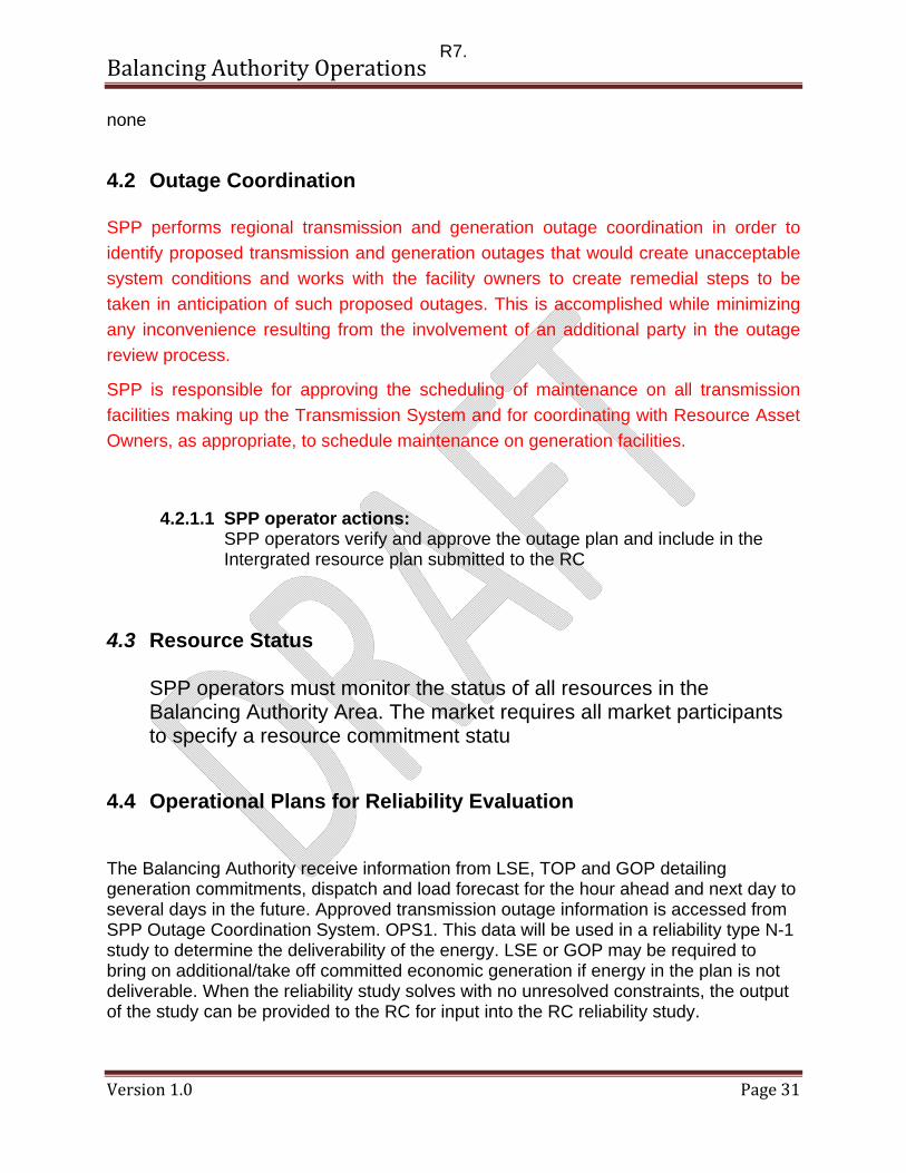
4.2 Outage Coordination SPP performs regional transmission and generation outage coordination in order to identify proposed transmission and generation outages that would create unacceptable system conditions and works with the facility owners to create remedial steps to be taken in anticipation of such proposed outages. This is accomplished while minimizing any inconvenience resulting from the involvement of an additional party in the outage review process.
SPP is responsible for approving the scheduling of maintenance on all transmission facilities making up the Transmission System and for coordinating with Resource Asset Owners, as appropriate, to schedule maintenance on generation facilities.
4.2.1.1 SPP operator actions: SPP operators verify and approve the outage plan and include in the Intergrated resource plan submitted to the RC
4.3 Resource Status SPP operators must monitor the status of all resources in the Balancing Authority Area. The market requires all market participants to specify a resource commitment statu
4.4 Operational Plans for Reliability Evaluation The Balancing Authority receive information from LSE, TOP and GOP detailing generation commitments, dispatch and load forecast for the hour ahead and next day to several days in the future. Approved transmission outage information is accessed from SPP Outage Coordination System. OPS1. This data will be used in a reliability type N-1 study to determine the deliverability of the energy. LSE or GOP may be required to bring on additional/take off committed economic generation if energy in the plan is not deliverable. When the reliability study solves with no unresolved constraints, the output of the study can be provided to the RC for input into the RC reliability study.
R7.
Balancing Authority Operations
Version 1.0 Page 32
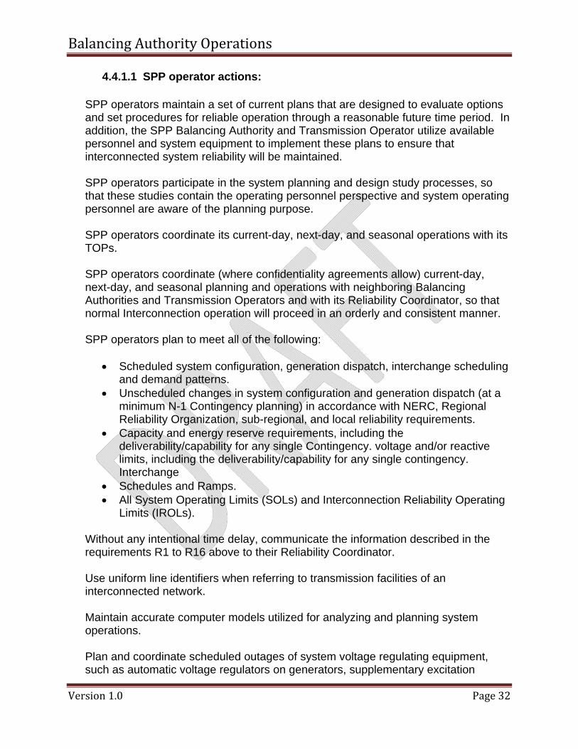
4.4.1.1 SPP operator actions:
SPP operators maintain a set of current plans that are designed to evaluate options and set procedures for reliable operation through a reasonable future time period. In addition, the SPP Balancing Authority and Transmission Operator utilize available personnel and system equipment to implement these plans to ensure that interconnected system reliability will be maintained.
SPP operators participate in the system planning and design study processes, so that these studies contain the operating personnel perspective and system operating personnel are aware of the planning purpose.
SPP operators coordinate its current-day, next-day, and seasonal operations with its TOPs.
SPP operators coordinate (where confidentiality agreements allow) current-day, next-day, and seasonal planning and operations with neighboring Balancing Authorities and Transmission Operators and with its Reliability Coordinator, so that normal Interconnection operation will proceed in an orderly and consistent manner.
SPP operators plan to meet all of the following:
• Scheduled system configuration, generation dispatch, interchange scheduling
and demand patterns. • Unscheduled changes in system configuration and generation dispatch (at a
minimum N-1 Contingency planning) in accordance with NERC, Regional Reliability Organization, sub-regional, and local reliability requirements.
• Capacity and energy reserve requirements, including the deliverability/capability for any single Contingency. voltage and/or reactive limits, including the deliverability/capability for any single contingency. Interchange
• Schedules and Ramps. • All System Operating Limits (SOLs) and Interconnection Reliability Operating
Limits (IROLs).
Without any intentional time delay, communicate the information described in the requirements R1 to R16 above to their Reliability Coordinator.
Use uniform line identifiers when referring to transmission facilities of an interconnected network.
Maintain accurate computer models utilized for analyzing and planning system operations.
Plan and coordinate scheduled outages of system voltage regulating equipment, such as automatic voltage regulators on generators, supplementary excitation
Balancing Authority Operations
Version 1.0 Page 33
control, synchronous condensers, shunt and series capacitors, reactors, etc., among affected Balancing Authorities and Transmission Operators as required.
Plan and coordinate scheduled outages of telemetering and control equipment and associated communication channels between the affected areas.
Balancing Authority Operations
Version 1.0 Page 34
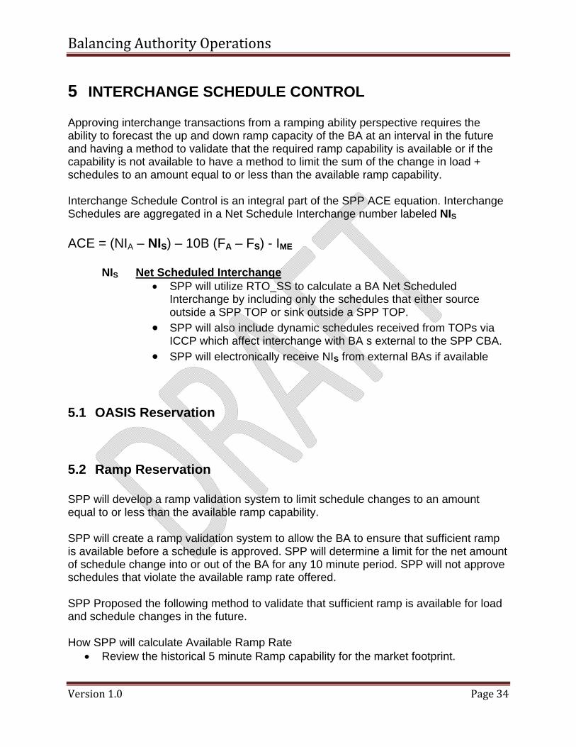
5 INTERCHANGE SCHEDULE CONTROL Approving interchange transactions from a ramping ability perspective requires the ability to forecast the up and down ramp capacity of the BA at an interval in the future and having a method to validate that the required ramp capability is available or if the capability is not available to have a method to limit the sum of the change in load + schedules to an amount equal to or less than the available ramp capability. Interchange Schedule Control is an integral part of the SPP ACE equation. Interchange Schedules are aggregated in a Net Schedule Interchange number labeled NIS ACE = (NIA – NIS) – 10B (FA – FS) - IME
NIS Net Scheduled Interchange • SPP will utilize RTO_SS to calculate a BA Net Scheduled
Interchange by including only the schedules that either source outside a SPP TOP or sink outside a SPP TOP.
• SPP will also include dynamic schedules received from TOPs via ICCP which affect interchange with BA s external to the SPP CBA.
• SPP will electronically receive NIS from external BAs if available
5.1 OASIS Reservation
5.2 Ramp Reservation
SPP will develop a ramp validation system to limit schedule changes to an amount equal to or less than the available ramp capability. SPP will create a ramp validation system to allow the BA to ensure that sufficient ramp is available before a schedule is approved. SPP will determine a limit for the net amount of schedule change into or out of the BA for any 10 minute period. SPP will not approve schedules that violate the available ramp rate offered. SPP Proposed the following method to validate that sufficient ramp is available for load and schedule changes in the future. How SPP will calculate Available Ramp Rate
• Review the historical 5 minute Ramp capability for the market footprint.
Balancing Authority Operations
Version 1.0 Page 35
• Determine which generators contribute to the historical available Ramp and their offer status (Available, Self Scheduled, Manual, Supplemental, Unavailable).
• Adjust the future available ramp based on the differences between the committed historical generators and the generators that are committed in the future time frame
• Adjust the future available ramp based on the differences between the offer status of historical generators and the offer status of generators committed in the future.
• When calculating the historical and future ramp rates, SPP will use the following criteria to determine which resources can be counted for 5 minute Available Ramp Rate:
• Available resources – Count the offered ramp rate. • Self Scheduled resources - Count the difference between the schedule at
the end of the 5 minute ramp and the schedule at the beginning of the 5 minute interval.
• Manual – Count the ramp rate as 0. • Supplemental – Count the Ramp rate as 0. • Unavailable – Count the Ramp rate as 0.
How SPP will calculate Required Ramp Rate
• Add the sum of the Self-Dispatched Internal schedules (not included in the BA NSI) and load change increases to the UP ramp requirement
• Add the sum of the Self Dispatched Internal schedules (not included in the BA NSI) and load change decreases to the DN ramp requirement
• If the Net Scheduled Interchange is negative, add to the DN ramp requirement • If the Net Scheduled Interchange is positive, add to the UP ramp requirement
How SPP will ensure the Ramp Rate is available to approve schedules
• Compare the Available Ramp Rate with the Required Ramp between intervals. • Approve the schedule if the Available Ramp Rate is greater than or equal to the
Required Ramp including the proposed schedule. • Deny the schedule if the Available Ramp Rate is less than the Required Ramp
including the proposed schedule. • To ensure sufficient regulation capability SPP will also limit the amount of
schedule changes inside the BAA for any 10 minute period. SPP will determine the amount of schedule change it can accommodate.
SPP will develop a method to track the offered ramp rate and the actual ramp rate of resources offered by each GOP.
• SPP will have a process in place to ensure that ramp reservations are justified and equitably distributed.
• SPP will monitor additional ramp capability available for reliability and deploy it as necessary.
SPP must perform the following to implement the proposed approach, including: • Determine a process for calculating external and internal ramp rate requirements
Balancing Authority Operations
Version 1.0 Page 36
• Develop a process for calculating the Available Ramp Rate in the BA. • Develop a method for limiting the total NSI change in any 10 minute period. • Develop a method for limiting the total internal schedule change in any 10 minute
or 20 minute period. • Develop a system to display the internal and external available ramp
requirements in the future. • Deny schedules that violate the Available Ramp Rate capability of the SPP
resources. See Bob’s Appendix
SPP member actions: • LSEs and GOPs will submit resource ramp rates that reflect the capability of the
resource.
5.3 Tagging
5.4 Evaluation of schedules The SPP CBA shall evaluate the Arranged Interchange with respect to:
• Energy profile (ability to support the magnitude of the Interchange). • Ramp (ability of generation maneuverability to accommodate). • Scheduling path (proper connectivity of Adjacent Balancing Authorities).
The Sending Balancing Authority and Receiving Balancing Authority shall agree on Interchange as received from the Interchange Authority, including:
• Interchange Schedule start and end time. • Energy profile.
Prior to the expiration of the time period defined in the Timing Table, Column B, the SPP BA shall respond to a request from an Interchange Authority to transition an Arranged Interchange to the Confirmed Interchange.
5.5 BTF Checkout
The SPP CBA Adjacent Balancing Authority Areas shall operate to a common Net Interchange Schedule value with Adjacent Balancing Authority Areas and shall record these hourly quantities, with like values but opposite sign
5.6 Schedule Implementation SPP as the Sink BA shall ensure that Arranged Interchange is submitted to the Interchange Authority:
Balancing Authority Operations
Version 1.0 Page 37
SPP as the Sink BA shall confirm Interchange Schedules with the Sending Balancing Authority prior to implementation in the Balancing Authority’s ACE equation. Approved schedules that cross BA boundaries will be included in the Net Scheduled Interchange used in the ACE calculation. SPP will monitor real-time dynamic schedules and incorporate them in its NSI for ACE calculation At such time as the reliability event allows for the reloading of the transaction, the entity that initiated the curtailment shall release the limit on the Interchange Transaction tag to allow reloading the transaction and shall communicate the release of the limit to the Sink Balancing Authority. The SPP CBA shall implement Confirmed Interchange as received from the Interchange Authority. When The SPP CBA experiences a loss of resources covered by an energy sharing agreement shall ensure that a request for an Arranged Interchange is submitted with a start time no more than 60 minutes beyond the resource loss. If the use of the energy sharing agreement does not exceed 60 minutes from the time of the resource loss, no request for Arranged Interchange is required.
During the implementation of relief procedures, and up to the point that emergency action is necessary, Reliability Coordinators and Balancing Authorities shall comply with interchange scheduling standards INT-001 through INT-004.
5.6.1 Energy Schedules
5.6.2 Dynamic Schedules Fixed Dynamic Interchange Schedules may be import, export or thorugh schedules. In each case, the scheduled amount as adjusted via market adjust to represent actual scheduled amount, represent amounts of energy to be transferred into, out of , through or within the SPP Balancing Authority Area. Dynamic Interchange sChedules are tagged to the applicable external BA. SPP RTO will be the transmission provider on Dynamic Interchange Schedules that use SPP transmission. Fixed Dynamic Interchange schedules The SPP operator monitors all dynamic schedules that touch the BAA. The SPP operator will work with the TOP to ensure that these values are correct for the SPP ACE equation. For details see the SPP Dynamic Schedule Procedure ########
Balancing Authority Operations
Version 1.0 Page 38
5.6.3 Capacity
Balancing Authority Operations
Version 1.0 Page 39
6 ACTUAL INTERCHANGE MANAGEMENT External interchange transactions between the SPP CBA and BA outside the SPP CBA footprint result in interchange schedules between the SPP CBA and these external Bas. These interchange values will be calculated to allow the SPP CBA to checkout hourly Energy (Mwh) values with these External BA Actual Interchange Management is an integral part of the SPP ACE equation. Actual Tie Line data are aggregated in a Net Actual Interchange number labeled NIA
ACE = (NIA – NIS) – 10B (FA – FS) - IME
NIA Net Actual Interchange • Each TOP will send all tie line flows to SPP. This will include all ties
with other MPs and external BAs. • Impacts of external market generators (pseudo-tied) will include the
Net Actual Interchange. • SPP CBA and MP will ensure the quality of meter data (esp with
ACE calc) –SPP will sum the tie line information for external BAs. • SPP CBA NIA will not include any Interconnect lines between SPP
TOPs.
6.1 Tie Line Meter Data The SPP RTO Scheduling Process Manual provides detailed processes and procedures for Scheduling Interchange Transactions in the SPP CBA. SPP currently confirms schedules as a Regional Scheduling Entity. SPP will register with NERC to become a BA. RTOSS will be modified to Accept SPP as the sink and Source BA on tagged transactions. SPP will validate and confirm scheduled transactions through the RTOSS tool. SPP CBA Scheduling System (RTOSS) will implement approved and modified schedules that cross SPP CBA boundaries into the ACE equation.
• SPP will become the Interchange Authority and scheduling entity for each LSE/PSE and evaluate schedules and schedule curtailments for the BA.
• SPP must perform the following to implement the proposed approach: Receive all interchange schedules including dynamic schedules from the IA via RTO_SS.
Balancing Authority Operations
Version 1.0 Page 40
• Evaluate all schedules including dynamic schedules from RTO_SS. RTOSS will create auto-validation of schedules where possible.
• Confirm all interchange schedules with IA via RTOSS • Approve schedules and modification of schedules that meet all the SPP
scheduling requirements including ramp rate. • Calculate a Net Scheduled Interchange using the approved schedules that cross
BA boundaries. • Use the calculated net scheduled interchange in the ACE calculation and send
the RDS via ICCP to the GOP or its designated entity. • Agree NSI with adjacent BA ATF checkout
Each GOP/LSE must send the actual dynamic schedule information to SPP via ICCP RTOSS does the following:
• implement generator commitment and dispatch schedules from the LSE and GOP who have arranged for generation within the SPP BA
• receive loss allocation from TSP – complete • receive interchange schedule curtailment info from IA • inform RC and IA of interchange schedule interruptions • calculate SCE for RZ
6.2 Tie Line checkout The SPP CBA will: • Calculate metered interchange and perform hourly and daily tie line meter MWH
check out with MP/TOP and neighboring BAs. • Facilitate meter checkout functions • Determine and provide mechanisms to apply meter corrections in accordance with
applicable agreements. Requirements for GOP/TOP/PSEs include: • Continue to read meters and determine necessary meter corrections in accordance
with applicable agreements.
• monitor, coordinate and reconcile tie line values
Balancing Authority Operations
Version 1.0 Page 41
• Develop accurate and complete real time Actual Interchange The SPP BA will develop a process to coordinate Tie Line values. The process will
include the following: • How the TOP will send the tie line data to SPP • Real time future meter correction coordination • Real time tie line measurement failure and coordinating the substitution of a
value. SPP CBA will reconcile meter readings and accumulated energy for each adjacent tie line and for each RZ tie lines. SPP CBA will calculate and record hourly Inadvertent Interchange SPP CBA includes all AC tie lines that connect to its Adjacent Balancing Authority Areas in its Inadvertent Interchange account including interchange served by jointly owned generators. SPP CBA ensures that all of its interconnection points are equipped with common megawatt-hour meters, with readings provided hourly to the control centers of Adjacent Balancing Authorities. SPP CBA operates to a common Net Actual Interchange value with its neighboring BA and records these hourly quantities, with like values but opposite sign. SPP CBA agree with its Adjacent Balancing Authorities to the hourly integrated megawatt-hour values of Net Actual Interchange.
6.3 HVDC Tie management Coordinate DC tie schedules The SPP Balancing Authority Area operates within the Eastern Interconnection. It is bounded on the south by the ERCOT Interconnection and on the West by the Western Interconnection. The SPP Balancing Authority is connected to the ERCOT interconnection by 2 individual HVDC ties: the North DC Tie and the South DC Tie. These ties are operated by the American Electric Power Transmission Operators. SPP is connected to the WECC by 5 individual HVDC ties: the ties are operated by Public Service of New Mexico, EXCEL ? WPP.
Balancing Authority Operations
Version 1.0 Page 42
SPP operators and EMS engineers monitor all HVDC ties and insure that these ties are modeled correctly in the SPP ACE equation. SPP as the Balancing Authority coordinates Interchange schedules a with the Transmission Operator of the specific HVDC tie. Coordination of these schedules as follows:
• Coordinate DC tie Ramp rate approval • Coordinate Meter corrections • Calculate of inadvertent across DC ties • Coordinate Payback of Inadvertent across DC ties.
Even though the HVDC ties are modeled as a resource internal to the SPP Balancing Authority Area, similar to a Pseudo-tied external resource, a transaction over an HVDC tie must have an associated Fixed Dynamic Interchange Scehdule to participate in the SPP Ancillary Service market (Day-Ahead and Real-Time Energy and Operating Reserves.
6.4 Joint Operated Units SPP operators and EMS engineers monitor all JOU’s and ensure that they are modeled correctly
6.5 Pseudo Ties SPP operators and EMS engineers monitor all Psuedo Ties (generation and load values) and ensure that these ties are modeled corxrectly in the SPP ACE equation .
Balancing Authority Operations
Version 1.0 Page 43
7 INADVERTENT MANAGEMENT Hourly inadvertent interchange is defined as the difference between hourly net actual interchange and hourly net scheduled interchange of a control area. Attachment H provides additional detail regarding BAL standard reporting requirements. It is caused by any of the following factors:
• Bias response to frequency deviations occurring on the interconnected system • Metering errors • inability of system generation to exactly match load • inability of system generation to exactly match net interchange schedule changes
Hourly inadvertent interchange may accumulate in a control area as a megawatt-hour credit or debit. It is accounted for each month. SPP maintains a record of the SPP BA accumulated inadvertent interchange for both On- and Off-Peak Periods as required by the NERC BAL standards. 1) Off-Peak Period is from 2300 to 0659 CPT, Monday thru Saturday, and all day Sundays and Holidays 2) On-Peak Period is from 0700 to 2259 CPT, Monday thru Saturday
Over time, SPP CBA attempts to minimize the amount of accumulated inadvertent interchange. This is accomplished by continually monitoring and correcting for inadvertent interchange. Correcting for Accumulation of Inadvertent Interchange It is the responsibility of SPP CBA operator to correct for the accumulation of inadvertent interchange. The reduction of an accumulation (on an On-Peak Period or Off-Peak Period basis as defined above) of inadvertent interchange is accomplished by one of the following two methods:
• Unilateral Payback —Unilateral Payback can only occur when the reduction of the accumulation of inadvertent is in a direction that serves to decrease the time error. An accumulation of under-generation can only be paid back (requiring the SPP Control Area to over-generate) when time error is less than zero (i.e., slow). Payback of an accumulation of over-generation (requiring the SPP RTO to under-generate) requires a time error greater than zero (i.e., fast).
• Bilateral Payback — Bilateral Payback is scheduled with another Control Area and is accomplished as follows: Inadvertent interchange accumulation may be reduced by scheduling a correction with any adjacent control area, provided they have an accumulation in the opposite direction. The amount of schedule established by SPP operator is determined by the following factors: • Amount of Accumulated inadvertent interchange
Balancing Authority Operations
Version 1.0 Page 44
• Current net interchange schedule in effect • Current state of the SPP Control Area with respect to load and transmission
facilities Energy accounting involves collecting schedules and MWH tie line metering data and verifying with MP/TOP and neighboring BAs that the correct values are used in inadvertent calculations in accordance with standard business practices. Administering inadvertent energy payback schedules includes determining on- and off-peak Inadvertent balances and determining the method of paying back inadvertent. Inadvertent payback can be done through bilateral schedules or unilaterally. SPP CBA is currently operating under a waiver and administers inadvertent payback for the market footprint. SPP CBA anticipates that its existing approach can be utilized in functioning as a BA for the existing market footprint. All entities functioning within the SPP BA must use RTO_SS so that SPP can automate collecting and checking out schedules. SPP will collect hourly MWH values on for each tie line meter (within and external to the BA) and calculate net actual interchange. The SPP CBA will: • Act as the scheduling entity (SC) and interchange authority (IA) for operating entities
in the SPP CBA. • Perform hourly and daily schedule checkout with MP • Perform hourly and daily schedule checkout with all neighboring BAs • Calculate metered interchange and perform hourly and daily tie line meter MWH
check out with MP/TOP and neighboring BAs. • Facilitate meter checkout functions • Determine and provide mechanisms to apply meter corrections in accordance with
applicable agreements. Requirements for GOP/TOP/PSEs include: • Continue to read meters and determine necessary meter corrections in accordance
with applicable agreements. Each Balancing Authority, by the end of the next business day, The SPP CBA shall agree with its Adjacent Balancing Authorities to the hourly values of Net Interchange Schedule
7.1 Checkout processes Calculate and record hourly Inadvertent Interchange. Include all AC tie lines that connect to its Adjacent Balancing Authority Areas in its Inadvertent Interchange account. The Balancing Authority shall take into account interchange served by jointly owned generators.
Balancing Authority Operations
Version 1.0 Page 45
7.2 Inadvertent Reporting Ensure all of its Balancing Authority Area interconnection points are equipped with common megawatt-hour meters, with readings provided hourly to the control centers of Adjacent Balancing Authorities. Operate to a common Net Interchange Schedule and Actual Net Interchange value and shall record these hourly quantities, with like values but opposite sign. Each Balancing Authority shall compute its Inadvertent Interchange based on the following: By the end of the next business day, shall agree with its Adjacent Balancing Authorities to:
• The hourly values of Net Interchange Schedule. • The hourly integrated megawatt-hour values of Net Actual Interchange.
Use the agreed-to daily and monthly accounting data to compile its monthly accumulated Inadvertent Interchange for the On-Peak and Off-Peak hours of the month.
7.3 Inadvertent Payback Provide its Reliability Coordinator with the operating data that the Reliability Coordinator requires to perform operational reliability assessments and to coordinate reliable operations within the Reliability Coordinator Area. TOP-005-1 Upon request, each Balancing Authority and Transmission Operator shall provide to other Balancing Authorities and Transmission Operators with immediate responsibility for operational reliability, the operating data that are necessary to allow these Balancing Authorities and Transmission Operators to perform operational reliability assessments and to coordinate reliable operations. Balancing Authorities and Transmission Operators shall provide the types of data as listed in Attachment 1-TOP-005-0 “Electric System Reliability Data,” unless otherwise agreed to by the Balancing Authorities and Transmission Operators with immediate responsibility for operational reliability.
7.3.1.1 SPP operator actions:
Balancing Authority Operations
Version 1.0 Page 46
7.3.1.2 SPP member actions:
7.3.1.3
Balancing Authority Operations
Version 1.0 Page 47
8 EMERGENCY OPERATIONS During a system emergency, the Balancing Authority and Transmission Operator shall immediately take action to restore the Real and Reactive Power Balance. If the Balancing Authority or Transmission Operator is unable to restore Real and Reactive Power Balance it shall request emergency assistance from the Reliability Coordinator. If corrective action or emergency assistance is not adequate to mitigate the Real and Reactive Power Balance, then the Reliability Coordinator, Balancing Authority, and Transmission Operator shall implement firm load shedding. . Each Transmission Operator, Balancing Authority, and Generator Operator shall render all available emergency assistance to others as requested, provided that the requesting entity has implemented its comparable emergency procedures, unless such actions would violate safety, equipment, or regulatory or statutory requirements. SPP, together with TOP, GOP and LSE annually develop, maintain and are prepared to implement an emergency operating plan that includes insufficient generation capacity, operating emergencies on the transmission system, load shedding and system restoration. The plan will include tasks to be performed by each entity, staffing levels and communication protocols. Plans for load shedding will be included where necessary to alleviate loading on the transmission system within the NERC guidelines. The existing TOP/BA emergency plans will provide much of the basis for the SPP emergency operating plan. SPP existing emergency contacts for the RC function should provide a starting point as a contact list for BA responsibility. SPP, as a BA, will need to determine which additional contacts are necessary for the appropriate reporting authorities during emergencies. SPP will Coordinate Emergency plans with the TOP, GOP, LSE and neighboring BAs at least annually and provide a copy of the plan to the RC, neighboring TOP and BAs. The SPP Emergency Operating Plan can be found in “SPP Emergency Operations Manual and it includes:
• Insufficient generation capacity. • Excessive generation capacity. • Operating Emergencies on the transmission system. • Emergency load shedding plans to resolve transmission operating emergencies
that must be resolved Immediately (IROL) to prevent uncontrolled failure of components or cascading outages of the interconnection.
• Load shedding for capacity shortages. • Black Start Plan • Islanding Plan • System Restoration Plan
Balancing Authority Operations
Version 1.0 Page 48
Appendix A: Glossary
A Area Control Error (ACE) - The instantaneous difference between a Balancing Authority’s net actual and scheduled interchange, taking into account the effects of Frequency Bias and correction for meter error. (NERC) Automatic Generation Control (AGC) - Equipment that automatically adjusts generation in a Balancing Authority Area from a central location to maintain the Balancing Authority’s interchange Schedule Plus Frequency Bias. AGC may also accommodate automatic inadvertent payback and time error correction. (NERC) Ancillary Service (AS) - Those services that are necessary to support the transmission of capacity and energy from resources to loads: while maintaining reliable operation of the Transmission Service Provider's transmission system in accordance with good utility practice. (From FERC order 888-A.) (NERC) Ancillary Services are regulation reserves and contingency reserves. B Balancing Authority - (BA) - The responsible entity that integrates resource plans ahead of time, maintains load-interchange-generation balance within a Balancing Authority Area, and supports Interconnection frequency in real time. (NERC) Balancing Authority Area (BAA) - The collection of generation, transmission, and loads within the metered boundaries of the Balancing Authority. The Balancing Authority maintains load resource balance within this area. (NERC) Balancing Authority ACE Limit (BAAL) - BAAL measures the number of consecutive clock minutes that the Balancing Authority’s ACE exceeds its BAAL, which is based upon the bias of the Balancing Authority, the Frequency Trigger Limit determined for the Interconnection, and the deviation of Actual Frequency from 60 Hz. BAAL requires that the Balancing Authority not exceed the BAAL for more than 30 consecutive clock-minutes. (NERC) C Control Performance Standard (CPS) - The reliability standard that sets the limits of a Balancing Authority’s Area Control Error over a specified time period. (NERC) Contingency Reserves - Spinning and Supplemental energy reserved on resources to respond to loss of generation contingencies. D
Balancing Authority Operations
Version 1.0 Page 49
Disturbance Control Standard (DCS) - The reliability standard that sets the time limit following a Disturbance within which a Balancing Authority must return its Area Control Error to within a specified range. (NERC) Dynamic Schedule - A telemetered reading or value that is updated in real time and used as a schedule in the AGC/ACE equation and the integrated value of which is treated as a schedule for interchange accounting purposes. Commonly used for scheduling jointly owned generation to or from another Balancing Authority Area. (NERC) E Energy Imbalance Market (EI Market) - The SPP Energy Imbalance Market Energy Management System (EMS) - A system of computer hardware and software that; accesses and manages transmission, generation and scheduling information for a defined area in the electrical grid. F Frequency Bias B - A value, usually expressed in megawatts per 0.1 Hertz (MW/0.1 Hz), associated with a Balancing Authority Area that approximates the Balancing Authority Area’s response to Interconnection frequency error. (NERC) Frequency Regulation - The ability of a Balancing Authority to help the Interconnection maintain Scheduled Frequency. This assistance can include both turbine governor response and Automatic Generation Control. (NERC) Frequency Response - (Equipment) The ability of a system or elements of the system to react or respond to a change in system frequency. (System) The sum of the change in demand, plus the change in generation, divided by the change in frequency, expressed in megawatts per 0.1 Hertz (MW/0.1 Hz). (NERC) G Generator Operator (GOP) - The entity that operates generating unit(s) and performs the functions of: supplying energy and Interconnected Operations Services. (NERC) H Host Balancing Authority – 1. A Balancing Authority that confirms and implements Interchange Transactions for a Purchasing Selling Entity that operates generation or serves customers directly within the Balancing Authority’s metered boundaries. 2. The Balancing Authority within whose metered boundaries a jointly owned unit is physically located. (NERC) I Interchange Distribution Calculator (IDC) - The NERC system that calculates flow on Flowgates in the Eastern Interconnection and creates the prescription of curtailments when a TLR is activated by a Reliability Coordinator.
Balancing Authority Operations
Version 1.0 Page 50
Implemented Interchange - The state where the Balancing Authority enters the Confirmed Interchange into its Area Control Error equation. (NERC) Inadvertent Interchange - The difference between the Balancing Authority’s Net Actual Interchange and Net Scheduled Interchange. (IA – IS) (NERC) Independent Power Producer (IPP) - Any entity that owns or operates an electricity generating facility that is not included in an electric utility’s rate base. This term includes, but is not limited to, co-generators and small power producers and all other non-utility electricity producers, such as exempt wholesale generators, who sell electricity. (NERC) Interchange Authority (IA) - The responsible entity that authorizes implementation of valid and balanced Interchange Schedules between Balancing Authority Areas, and ensures communication of Interchange information for reliability assessment purposes. (NERC) Interchange Schedule - An agreed-upon Interchange Transaction size (megawatts), start and end time, beginning and ending ramp times and rate, and type required for delivery and receipt of power and energy between the Source and Sink Balancing Authorities involved in the transaction. (NERC) Interchange Transaction - An agreement to transfer energy from a seller to a buyer that crosses one or more Balancing Authority Area boundaries. (NERC) Tag - Interchange Transaction Tag - The details of an Interchange Transaction required for its physical implementation. (NERC) Interconnection Reliability Operating Limit (IROL) - A System Operating Limit that, if violated, could lead to instability, uncontrolled separation, or Cascading Outages that adversely impact the reliability of the Bulk Electric System. (NERC) J, K L Load Serving Entity (LSE) - Secures energy and transmission service (and related Interconnected Operations Services) to serve the electrical demand and energy requirements of its end use customers. (NERC) L10 L10=1.65∈10 (−10Bi) (−10Bs)
Each Balancing Authority shall operate such that its average ACE for at least 90% of clock ten-minute periods (6 non-overlapping periods per hour) during a calendar month is within a specific limit, referred to as L10. (NERC)
Balancing Authority Operations
Version 1.0 Page 51
For Balancing Authority Areas with variable bias, Bs is equal to the sum of the minimum Frequency Bias Settings. ∈10 is a constant derived from the targeted frequency bound. It is the targeted root-mean-square (RMS) value of ten-minute average Frequency Error based on frequency performance over a given year. The bound, ∈10, is the same for every Balancing Authority Area within an Interconnection, and Bs is the sum of the Frequency Bias Settings of the Balancing Authority Areas in the respective Interconnection. Bi is the Frequency Bias of the Balancing Authority Area. M Market Operating System (MOS) - The SPP system that creates Locational Imbalance Price (LIP) and Security Constrained Energy Imbalance deployments and sends them out to generators in the SPP Energy Imbalance Market. Market Flow Calculator (MFC) - The SPP Market system that calculates the amount of market flow, tagged flow and untagged flow that is on a Flowgate. Megawatt (MW) - 1,000 Kilowatts. An instantaneous measure of electrical energy that if maintained at that level for 1 hour would measure 1 Megawatt hour. Megawatt hour (MWH) - A measure of electrical energy equal to an accumulation of 1,000 Kilowatts measured at a point in 60 clock minutes. N Net Actual Interchange (NAI) - The algebraic sum of all metered interchange over all interconnections between two physically Adjacent Balancing Authority Areas. (NERC) Net Interchange Schedule (NIS) - The algebraic sum of all Interchange Schedules with each Adjacent Balancing Authority. (NERC) Net Scheduled Interchange (NSI) - The algebraic sum of all Interchange Schedules across a given path or between Balancing Authorities for a given period or instant in time. (NERC) Non Spinning Reserve (Supplemental Reserve) 1. That generating reserve not connected to the system but capable of serving demand within a specified time. 2. Interruptible load that can be removed from the system in a specified time. (NERC) O Open Access Technology Incorporated (OATI) - A vendor that provides scheduling and tagging software in the Eastern Interconnection.
Balancing Authority Operations
Version 1.0 Page 52
Operating Control Task Force (OCTF) - The task force in SPP that studied and submitted a Balancing Area consolidation feasibility study to SPP and FERC in February 2005. Operating Plan - A document that identifies a group of activities that may be used to achieve some goal. An Operating Plan may contain Operating Procedures and Operating Processes. A company-specific system restoration plan that includes an Operating Procedure for black-starting units, Operating Processes for communicating restoration progress with other entities, etc., is an example of an Operating Plan. (NERC) Operating Procedure - A document that identifies specific steps or tasks that should be taken by one or more specific operating positions to achieve specific operating goal(s). The steps in an Operating Procedure should be followed in the order in which they are presented, and should be performed by the position(s) identified. A document that lists the specific steps for a system operator to take in removing a specific transmission line from service is an example of an Operating Procedure. (NERC) Operating Reserve - That capability above firm system demand required to provide for regulation, load forecasting error, equipment forced and scheduled outages and local area protection. It consists of spinning and non-spinning reserve. (NERC) Operating Reserve Spinning – The portion of Operating Reserve consisting of: • Generation synchronized to the system and fully available to serve load within the Disturbance Recovery Period following the contingency event; or • Load fully removable from the system within the Disturbance Recovery Period following the contingency event. (NERC) Operating Reserve Supplemental The portion of Operating Reserve consisting of: • Generation (synchronized or capable of being synchronized to the system) that is fully available to serve load within the Disturbance Recovery Period following the contingency event; or • Load fully removable from the system within the Disturbance Recovery Period following the contingency event. (NERC) Operations Planning System (OPS1) - The SPP web based operations information system. Data is input by BAs and used by SPP as operational input for studies and processes. SPP posts study results and operational information for BAs on OPS1. P Peak Demand – 1. The highest hourly integrated Net Energy For Load within a Balancing Authority Area occurring within a given period (e.g., day, month, season, or year).
Balancing Authority Operations
Version 1.0 Page 53
2. The highest instantaneous demand within the Balancing Authority Area. (NERC) Point of Delivery (POD) - A location that the Transmission Service Provider specifies on its transmission system where an Interchange Transaction leaves or a Load-Serving Entity receives its energy. (NERC) Point of Receipt (POR) - A location that the Transmission Service Provider specifies on its transmission system where an Interchange Transaction enters or a Generator delivers its output. (NERC) Pseudo Tie - A telemetered reading or value that is updated in real time and used as a “virtual” tie line flow in the AGC/ACE equation but for which no physical tie or energy metering actually exists. The integrated value is used as a metered MWh value for interchange accounting purposes. (NERC) Purchasing Selling Entity (PSE) - The entity that purchases or sells, and takes title to, energy, capacity, and Interconnected Operations Services. Purchasing-Selling Entities may be affiliated or unaffiliated merchants and may or may not own generating facilities. (NERC) Q R Ramp Rate or Ramp - (Schedule) The rate, expressed in megawatts per minute, at which the interchange schedule is attained during the ramp period. (Generator) The rate, expressed in megawatts per minute, that a generator changes its output. (NERC) Reactive Power - The portion of electricity that establishes and sustains the electric and magnetic fields of alternating-current equipment. Reactive power must be supplied to most types of magnetic equipment, such as motors and transformers. It also must supply the reactive losses on transmission facilities. Reactive power is provided by generators, synchronous condensers, or electrostatic equipment such as capacitors and directly influences electric system voltage. It is usually expressed in kilovars (kvar) or megavars (Mvar). (NERC) Real Time - Present time as opposed to future time. (From Interconnection Reliability Operating Limits standard.) (NERC) Regulating Reserve - An amount of reserve responsive to Automatic Generation Control, which is sufficient to provide normal regulating margin. (NERC) Regulation Service - The process whereby one Balancing Authority contracts to provide corrective response to all or a portion of the ACE of another Balancing Authority. The Balancing Authority providing the response assumes the obligation of
Balancing Authority Operations
Version 1.0 Page 54
meeting all applicable control criteria as specified by NERC for itself and the Balancing Authority for which it is providing the Regulation Service. (NERC) Regulation Deployment Signal (RDS) - The SPP calculated number that represents the GOP portion of the SPP BA ACE. SPP calculates a SCE for each GOP. SPP calculates the BA ACE. If the GOP SCE and BA ACE are off in the same direction, the GOP will be sent a number that is the SCE pro rata share of the BA ACE. If the GOP SCE is off in the opposite direction than the BA ACE, a 0 regulation deployment signal will be sent. The block RDS is the GOP share of the BA regulation requirement calculated to correct the BA ACE. The block RDS is not broken down by individual resource for the GOP. The GOP will add the block RDS to its total generation requirement and allocate the block to individual resources based on the procedures the GOP develops. Reportable Disturbance - Any event that causes an ACE change greater than or equal to 80% of a Balancing Authority’s or reserve sharing group’s most severe contingency. The definition of a reportable disturbance is specified by each Regional Reliability Organization. This definition may not be retroactively adjusted in response to observed performance. (NERC) Regional Reliability Organization (RRO) – 1. An entity that ensures that a defined area of the Bulk Electric System is reliable, adequate and secure. 2. A member of the North American Electric Reliability Council. The Regional Reliability Organization can serve as the Compliance Monitor. Reserve Sharing Group (RSG) - A group, whose members consist of two or more Balancing Authorities that collectively maintain, allocate, and supply operating reserves required for each Balancing Authority’s use in recovering from contingencies within the group. Scheduling energy from an Adjacent Balancing Authority to aid recovery need not constitute reserve sharing provided the transaction is ramped in over a period the supplying party could reasonably be expected to load generation in (e.g., ten minutes). If the transaction is ramped in quicker (e.g., between zero and ten minutes) then, for the purposes of Disturbance Control Performance, the Areas become a Reserve Sharing Group. (NERC) Reserve Sharing System (RSS) - The computer system that receives the contingency loss information and creates and sends out contingency schedules in the SPP Reserve sharing group. Real Time Operations Scheduling System (RTO_SS) - The scheduling system used by the SPP to access, evaluate and act on schedule request in real time. S
Balancing Authority Operations
Version 1.0 Page 55
Scheduled Frequency - 60.0 Hertz, except during a time correction. (NERC) Schedule Control Error (SCE) - Net Actual Interchange - Net Scheduled Interchange - Meter Error for the TOP. (NIA – NIS - IME) SCE is used by SPP to allocate to each GOP the RDS to correct the SPP ACE. Scheduling Entity - An entity responsible for approving and implementing Interchange Schedules. (NERC) Sending Balancing Authority - The Balancing Authority exporting the Interchange. (NERC) Simultaneous Feasibility Study Day Ahead (SFTDA) - A software program that runs an N-1 study to determine the deliverability of the resource plan submitted for the next operating day in the SPP Market. Sink Balancing Authority - The Balancing Authority in which the load (sink) is located for an Interchange Transaction. (This will also be a Receiving Balancing Authority for the resulting Interchange Schedule.) (NERC) Source Balancing Authority - The Balancing Authority in which the generation (source) is located for an Interchange Transaction. (This will also be a Sending Balancing Authority for the resulting Interchange Schedule.) (NERC) SPP Consolidated Balancing Authority - The Entity that has the responsibility for integrating resource plans ahead of time and maintains load-interchange-generation balance within the SPP Consolidated Balancing Authority Area, and for supporting interconnection frequency in real time. SPP Consolidated Balancing Authority Area – A collection of SPP Balancing Zones SPP Balancing Authority – A collection of transmission, generation, and loads within a specific metered boundary (former SPP Balancing Authority Areas) NOTE: this definition was approved to be used until such time that the SPP Ancillary Services market begins and other entities choose to join the SPP CBA Southwest Power Pool (SPP) - The operating entity based in Little Rock, Arkansas that will assume the responsibility for the Balancing Authority Area if BA consolidation takes place. The SPP membership includes Balancing Authorities, Transmission Operators, Generator Operators and Load Serving Entities for which SPP is already one or all of the following 1) Market Operator 2) Reliability Authority 3) Interchange Authority. Special Protection System (SPS) - An automatic protection system designed to detect abnormal or predetermined system conditions, and take corrective actions other than and/or in addition to the isolation of faulted components to maintain system reliability.
Balancing Authority Operations
Version 1.0 Page 56
Such action may include changes in demand, generation (MW and Mvar), or system configuration to maintain system stability, acceptable voltage, or power flows. An SPS does not include (a) under-frequency or under-voltage load shedding or (b) fault conditions that must be isolated or (c) out-of-step relaying (not designed as an integral part of an SPS). Also called Remedial Action Scheme. (NERC) Spinning Reserve - Unloaded generation that is synchronized and ready to serve additional demand. (NERC) System Control and Data Acquisition (SCADA) - A system of remote control and telemetry used to monitor and control the transmission system. (NERC) Supplemental Regulation Service - A method of providing regulation service in which the Balancing Authority providing the regulation service receives a signal representing all or a portion of the other Balancing Authority’s ACE. (NERC) Supplemental Reserve - Offline or unloaded spinning reserve that can be fully synchronized and applied in 10 minutes or less. In SPP 50% of the contingency reserves must be Spinning and 50% may be Supplemental. System Operator - An individual at a control center (Balancing Authority, Transmission Operator, Generator Operator, Reliability Coordinator) whose responsibility it is to monitor and control that electric system in real time. (NERC) T Tie Line - A circuit connecting two Balancing Authority Areas. (NERC) Tie Line Bias - A mode of Automatic Generation Control that allows the Balancing Authority to 1. Maintain its Interchange Schedule and 2. Respond to Interconnection frequency error. (NERC) Time Error - The difference between the Interconnection time measured at the Balancing Authority (ies) and the time specified by the National Institute of Standards and Technology. Time error is caused by the accumulation of Frequency Error over a given period. (NERC) Time Error Correction - An offset to the Interconnection’s scheduled frequency to return the Interconnection’s Time Error to a predetermined value. (NERC) Transmission Operator (TOP) - The entity responsible for the reliability of its “local” transmission system, and that operates or directs the operations of the transmission facilities. (NERC) U, V, W, X, Y, Z
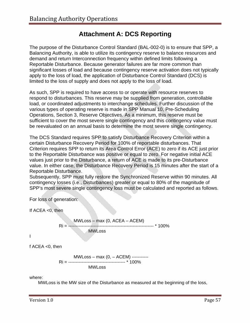
Balancing Authority Operations
Version 1.0 Page 57
Attachment A: DCS Reporting The purpose of the Disturbance Control Standard (BAL-002-0) is to ensure that SPP, a Balancing Authority, is able to utilize its contingency reserve to balance resources and demand and return Interconnection frequency within defined limits following a Reportable Disturbance. Because generator failures are far more common than significant losses of load and because contingency reserve activation does not typically apply to the loss of load, the application of Disturbance Control Standard (DCS) is limited to the loss of supply and does not apply to the loss of load. As such, SPP is required to have access to or operate with resource reserves to respond to disturbances. This reserve may be supplied from generation, controllable load, or coordinated adjustments to interchange schedules. Further discussion of the various types of operating reserve is made in SPP Manual 10, Pre-Scheduling Operations, Section 3, Reserve Objectives. As a minimum, this reserve must be sufficient to cover the most severe single contingency and this contingency value must be reevaluated on an annual basis to determine the most severe single contingency. The DCS Standard requires SPP to satisfy Disturbance Recovery Criterion within a certain Disturbance Recovery Period for 100% of reportable disturbances. That Criterion requires SPP to return its Area Control Error (ACE) to zero if its ACE just prior to the Reportable Disturbance was positive or equal to zero. For negative initial ACE values just prior to the Disturbance, a return of ACE is made to its pre-Disturbance value. In either case, the Disturbance Recovery Period is 15 minutes after the start of a Reportable Disturbance. Subsequently, SPP must fully restore the Synchronized Reserve within 90 minutes. All contingency losses (i.e., Disturbances) greater or equal to 80% of the magnitude of SPP’s most severe single contingency loss must be calculated and reported as follows. For loss of generation: If ACEA <0, then
MWLoss – max (0, ACEA – ACEM) Ri = --------------------------------------------------------- * 100%
MWLoss I f ACEA <0, then
MWLoss – max (0, – ACEM) ----------- Ri = -------------------------------------- * 100%
MWLoss where:
MWLoss is the MW size of the Disturbance as measured at the beginning of the loss,
Balancing Authority Operations
Version 1.0 Page 58
ACE is the pre-disturbance ACE, and ACEM is the maximum algebraic value of ACE measured within 15 minutes following the Disturbance. (Note: ACEM may be set to equal ACE15 min).
The recording of the MW Loss value should be measured at the site of the loss to the extent possible. This value should not be measured as a change in ACE since governor response (and AGC response) may introduce error. The value for ACEA shall be based on the average ACE over the period just prior to the start of the Disturbance (10 and 60 seconds prior and including at least 4 scans of ACE). The average percent recovery is the arithmetic average of all the calculated Ri values for Reportable Disturbances during a given quarter. Average percent recovery is similarly calculated for excludable Disturbances. These Disturbances are reported to NERC on a quarterly basis. Additionally, it is important to note that multiple contingencies occurring within one minute or less of each other are treated as a single contingency. However, if the combined magnitude of the multiple contingencies exceeds the most severe single contingency, the loss shall be reported, but excluded from the compliance evaluation (as described above). Additional contingencies that occur after one minute of the start of a Reportable Disturbance but end prior to the end of the Disturbance Recovery Period can be excluded from evaluation as well. Instead, SPP can determine the DCS compliance of the initial Reportable Disturbance by performing a reasonable estimation of the response that would have occurred had the second and subsequent contingencies not occurred.
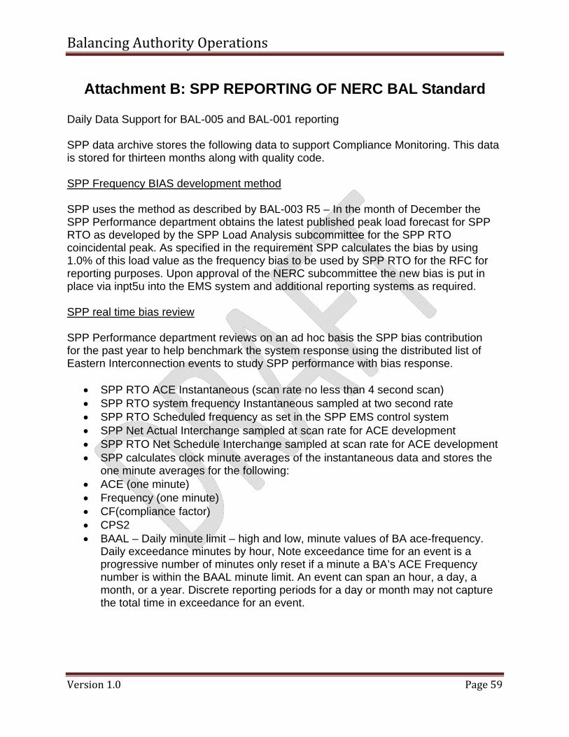
Balancing Authority Operations
Version 1.0 Page 59
Attachment B: SPP REPORTING OF NERC BAL Standard Daily Data Support for BAL-005 and BAL-001 reporting SPP data archive stores the following data to support Compliance Monitoring. This data is stored for thirteen months along with quality code. SPP Frequency BIAS development method SPP uses the method as described by BAL-003 R5 – In the month of December the SPP Performance department obtains the latest published peak load forecast for SPP RTO as developed by the SPP Load Analysis subcommittee for the SPP RTO coincidental peak. As specified in the requirement SPP calculates the bias by using 1.0% of this load value as the frequency bias to be used by SPP RTO for the RFC for reporting purposes. Upon approval of the NERC subcommittee the new bias is put in place via inpt5u into the EMS system and additional reporting systems as required. SPP real time bias review SPP Performance department reviews on an ad hoc basis the SPP bias contribution for the past year to help benchmark the system response using the distributed list of Eastern Interconnection events to study SPP performance with bias response.
• SPP RTO ACE Instantaneous (scan rate no less than 4 second scan) • SPP RTO system frequency Instantaneous sampled at two second rate • SPP RTO Scheduled frequency as set in the SPP EMS control system • SPP Net Actual Interchange sampled at scan rate for ACE development • SPP RTO Net Schedule Interchange sampled at scan rate for ACE development • SPP calculates clock minute averages of the instantaneous data and stores the
one minute averages for the following: • ACE (one minute) • Frequency (one minute) • CF(compliance factor) • CPS2 • BAAL – Daily minute limit – high and low, minute values of BA ace-frequency.
Daily exceedance minutes by hour, Note exceedance time for an event is a progressive number of minutes only reset if a minute a BA’s ACE Frequency number is within the BAAL minute limit. An event can span an hour, a day, a month, or a year. Discrete reporting periods for a day or month may not capture the total time in exceedance for an event.
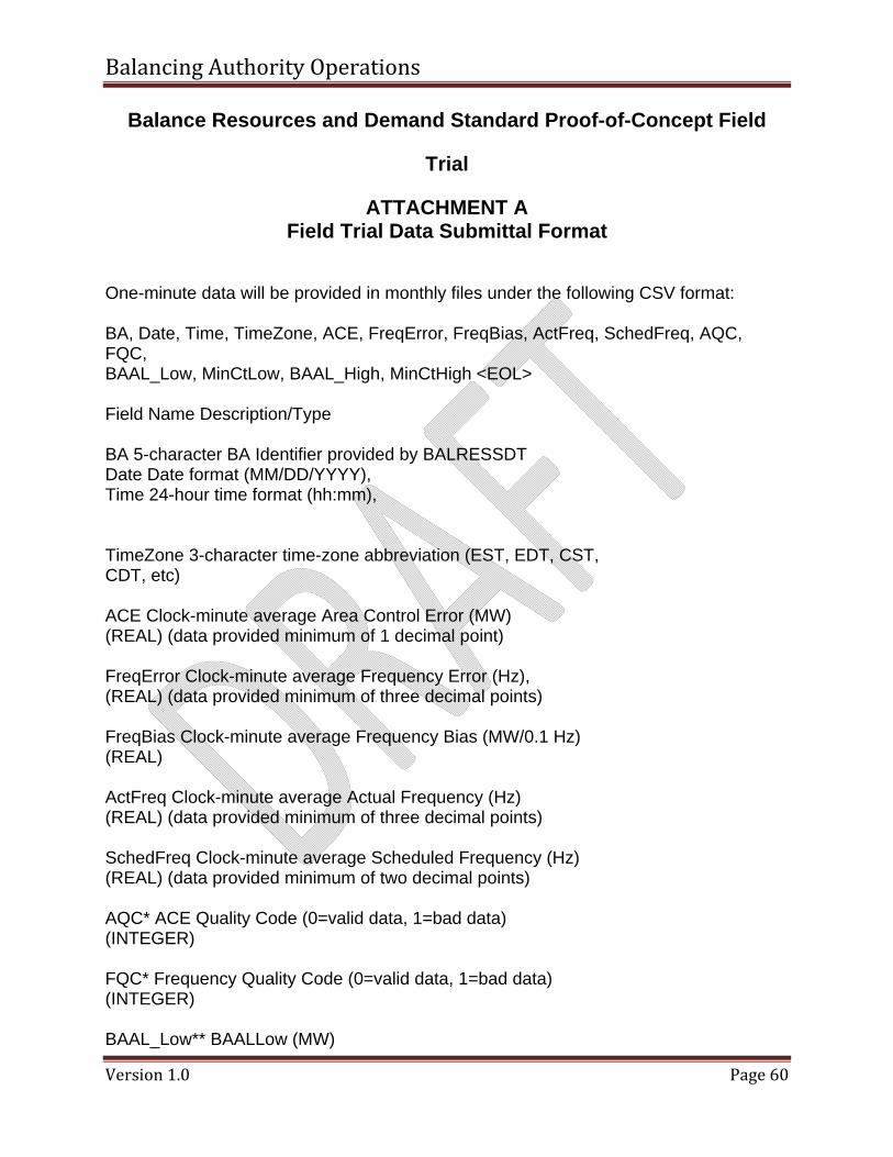
Balancing Authority Operations
Version 1.0 Page 60
Balance Resources and Demand Standard Proof-of-Concept Field
Trial
ATTACHMENT A Field Trial Data Submittal Format
One-minute data will be provided in monthly files under the following CSV format: BA, Date, Time, TimeZone, ACE, FreqError, FreqBias, ActFreq, SchedFreq, AQC, FQC, BAAL_Low, MinCtLow, BAAL_High, MinCtHigh <EOL> Field Name Description/Type BA 5-character BA Identifier provided by BALRESSDT Date Date format (MM/DD/YYYY), Time 24-hour time format (hh:mm), TimeZone 3-character time-zone abbreviation (EST, EDT, CST, CDT, etc) ACE Clock-minute average Area Control Error (MW) (REAL) (data provided minimum of 1 decimal point) FreqError Clock-minute average Frequency Error (Hz), (REAL) (data provided minimum of three decimal points) FreqBias Clock-minute average Frequency Bias (MW/0.1 Hz) (REAL) ActFreq Clock-minute average Actual Frequency (Hz) (REAL) (data provided minimum of three decimal points) SchedFreq Clock-minute average Scheduled Frequency (Hz) (REAL) (data provided minimum of two decimal points) AQC* ACE Quality Code (0=valid data, 1=bad data) (INTEGER) FQC* Frequency Quality Code (0=valid data, 1=bad data) (INTEGER) BAAL_Low** BAALLow (MW)
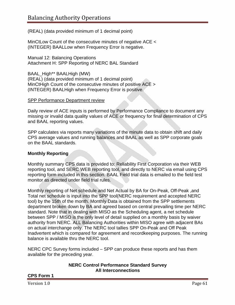
Balancing Authority Operations
Version 1.0 Page 61
(REAL) (data provided minimum of 1 decimal point) MinCtLow Count of the consecutive minutes of negative ACE < (INTEGER) BAALLow when Frequency Error is negative. Manual 12: Balancing Operations Attachment H: SPP Reporting of NERC BAL Standard BAAL_High** BAALHigh (MW) (REAL) (data provided minimum of 1 decimal point) MinCtHigh Count of the consecutive minutes of positive ACE > (INTEGER) BAALHigh when Frequency Error is positive. SPP Performance Department review Daily review of ACE inputs is performed by Performance Compliance to document any missing or invalid data quality values of ACE or frequency for final determination of CPS and BAAL reporting values. SPP calculates via reports many variations of the minute data to obtain shift and daily CPS average values and running balances and BAAL as well as SPP corporate goals on the BAAL standards. Monthly Reporting Monthly summary CPS data is provided to: Reliability First Corporation via their WEB reporting tool, and SERC WEB reporting tool, and directly to NERC via email using CPS reporting form included in this section. BAAL Field trial data is emailed to the field test monitor as directed under field trial rules. Monthly reporting of Net schedule and Net Actual by BA for On-Peak, Off-Peak ,and Total net schedule is input into the SPP tool(NERC requirement and accepted NERC tool) by the 15th of the month. Monthly Data is obtained from the SPP settlements department broken down by BA and agreed based on central prevailing time per NERC standard. Note that in dealing with MISO as the Scheduling agent, a net schedule between SPP / MISO is the only level of detail supplied on a monthly basis by waiver authority from NERC. ALL Balancing Authorities within MISO agree with adjacent BAs on actual interchange only. The NERC tool tallies SPP On-Peak and Off Peak Inadvertent which is compared for agreement and recordkeeping purposes. The running balance is available thru the NERC tool. NERC CPC Survey forms included – SPP can produce these reports and has them available for the preceding year.
NERC Control Performance Standard Survey All Interconnections
CPS Form 1
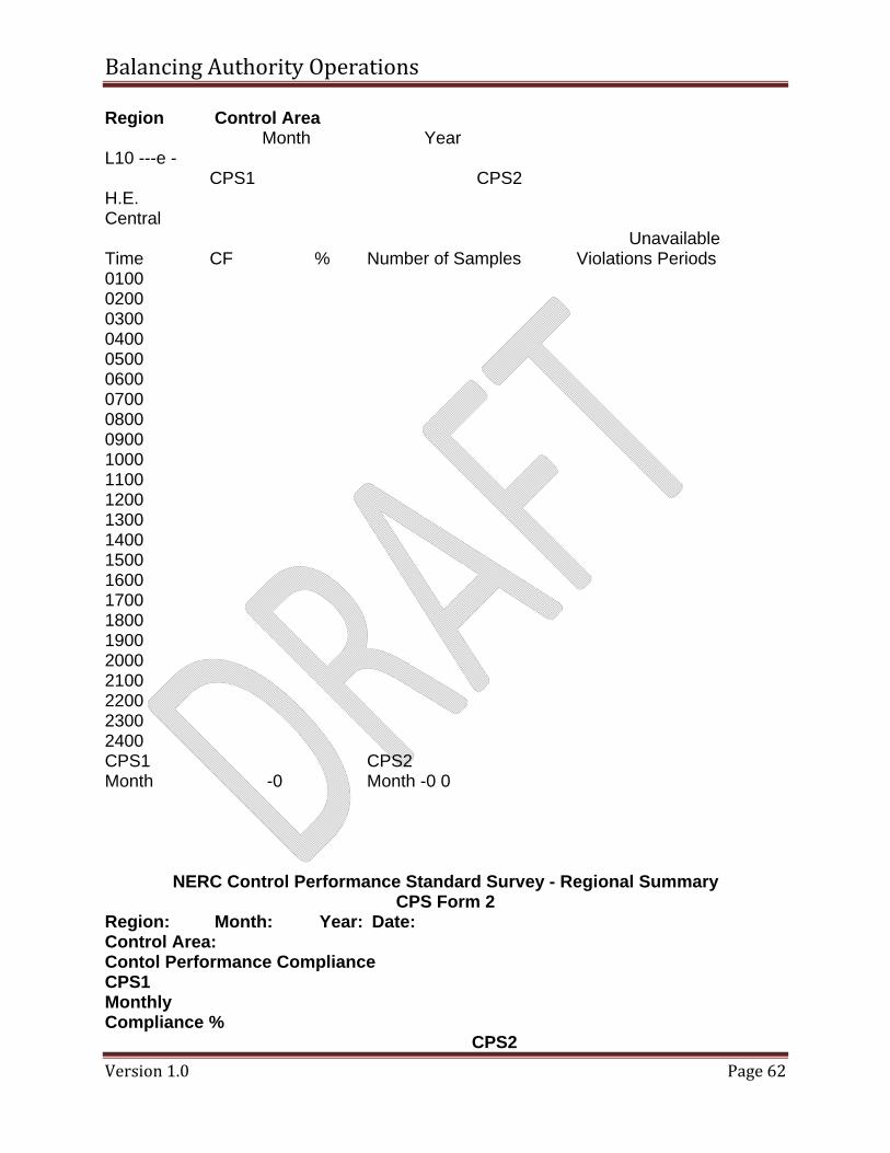
Balancing Authority Operations
Version 1.0 Page 62
Region Control Area Month Year
L10 ---e - CPS1 CPS2
H.E. Central
Unavailable Time CF % Number of Samples Violations Periods 0100 0200 0300 0400 0500 0600 0700 0800 0900 1000 1100 1200 1300 1400 1500 1600 1700 1800 1900 2000 2100 2200 2300 2400 CPS1 CPS2 Month -0 Month -0 0
NERC Control Performance Standard Survey - Regional Summary CPS Form 2
Region: Month: Year: Date: Control Area: Contol Performance Compliance CPS1 Monthly Compliance %
CPS2
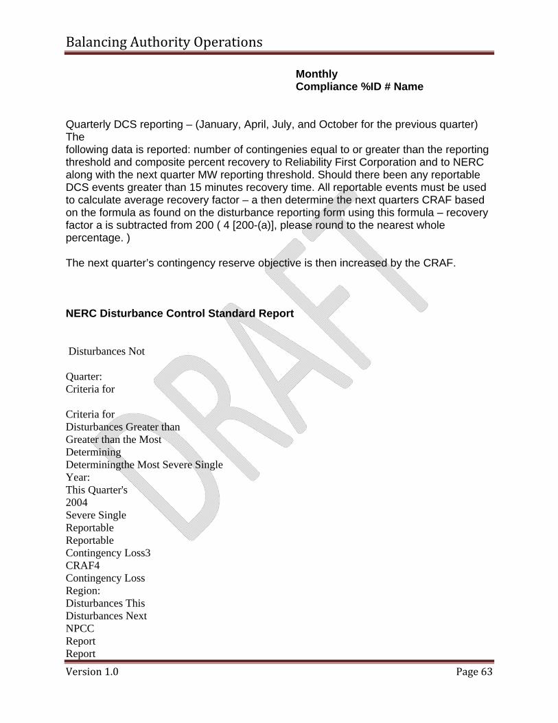
Balancing Authority Operations
Version 1.0 Page 63
Monthly Compliance %ID # Name
Quarterly DCS reporting – (January, April, July, and October for the previous quarter) The following data is reported: number of contingenies equal to or greater than the reporting threshold and composite percent recovery to Reliability First Corporation and to NERC along with the next quarter MW reporting threshold. Should there been any reportable DCS events greater than 15 minutes recovery time. All reportable events must be used to calculate average recovery factor – a then determine the next quarters CRAF based on the formula as found on the disturbance reporting form using this formula – recovery factor a is subtracted from 200 ( 4 [200-(a)], please round to the nearest whole percentage. ) The next quarter’s contingency reserve objective is then increased by the CRAF. NERC Disturbance Control Standard Report Disturbances Not Quarter: Criteria for Criteria for Disturbances Greater than Greater than the Most Determining Determiningthe Most Severe Single Year: This Quarter's 2004 Severe Single Reportable Reportable Contingency Loss3 CRAF4 Contingency Loss Region: Disturbances This Disturbances Next NPCC Report Report
Balancing Authority Operations
Version 1.0 Page 64
Number APR2 (a) Number APR Control Area/RSG1: 100.00 100.00 100.00 0.80 80% When reporting as a Reserve Sharing Group (RSG), submit data for the entire group only and list the Control Areas comprising the RSG.
Balancing Authority Operations
Version 1.0 Page 65
Attachment C: Frequency Survey Form SPP upon request from NERC or RFC and hourly Frequency Survey is filled out following the NERC Frequency Response Characteristic Survey as documented below . Issuance of Survey Instructions for FRC Survey Survey will be submitted to the Region and NERC for review by the committee representatives along with the compiling of report data.
NERC FRC Survey Tool Entry Form
details
Balancing Authority Operations
Version 1.0 Page 66
Attachment D: AIE Survey Form SPP upon request from NERC or RFC and hourly Area Interchange Error Survey is filled out containing information as listed below Requestor determines the Date and Hour(s) and supplied the Frequency Error. SPP will supply the six ten minute samples compute the total ACE, Average ACE, Adjusted AIE and provide the L10 and frequency Bias as used in the system. Compute the Control Error as a percentage of L10. Sample AIE report below – forms sent to BA by requestor.
NERC AIE Survey Tool Entry Form
details
Balancing Authority Operations
Version 1.0 Page 67
Attachment E: NERC Inadvertent Reporting Tool
NERC Tool Entry Form
details
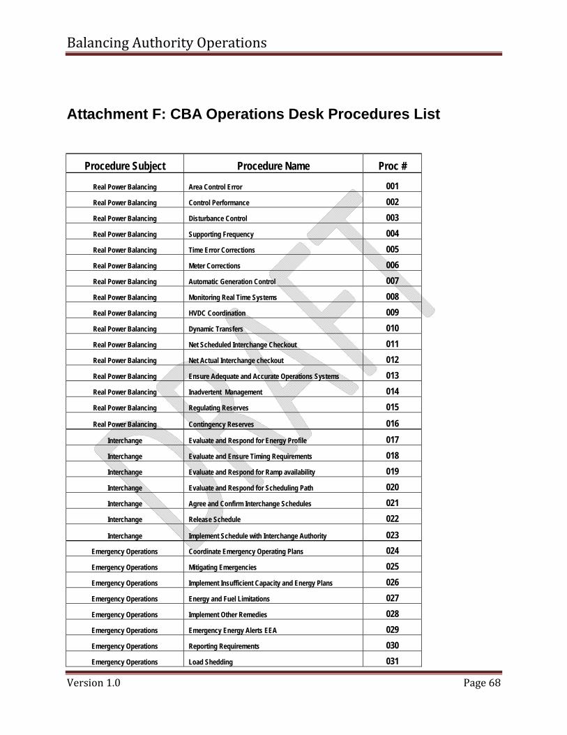
Balancing Authority Operations
Version 1.0 Page 68
Attachment F: CBA Operations Desk Procedures List
Procedure Subject Procedure Name Proc #
Real Power Balancing Area Control Error 001 Real Power Balancing Control Performance 002 Real Power Balancing Disturbance Control 003 Real Power Balancing Supporting Frequency 004 Real Power Balancing Time Error Corrections 005 Real Power Balancing Meter Corrections 006 Real Power Balancing Automatic Generation Control 007 Real Power Balancing Monitoring Real Time Systems 008 Real Power Balancing HVDC Coordination 009 Real Power Balancing Dynamic Transfers 010 Real Power Balancing Net Scheduled Interchange Checkout 011 Real Power Balancing Net Actual Interchange checkout 012 Real Power Balancing Ensure Adequate and Accurate Operations Systems 013 Real Power Balancing Inadvertent Management 014 Real Power Balancing Regulating Reserves 015
Real Power Balancing Contingency Reserves 016
Interchange Evaluate and Respond for Energy Profile 017 Interchange Evaluate and Ensure Timing Requirements 018 Interchange Evaluate and Respond for Ramp availability 019 Interchange Evaluate and Respond for Scheduling Path 020 Interchange Agree and Confirm Interchange Schedules 021 Interchange Release Schedule 022
Interchange Implement Schedule with Interchange Authority 023 Emergency Operations Coordinate Emergency Operating Plans 024 Emergency Operations Mitigating Emergencies 025 Emergency Operations Implement Insufficient Capacity and Energy Plans 026 Emergency Operations Energy and Fuel Limitations 027 Emergency Operations Implement Other Remedies 028 Emergency Operations Emergency Energy Alerts EEA 029 Emergency Operations Reporting Requirements 030 Emergency Operations Load Shedding 031
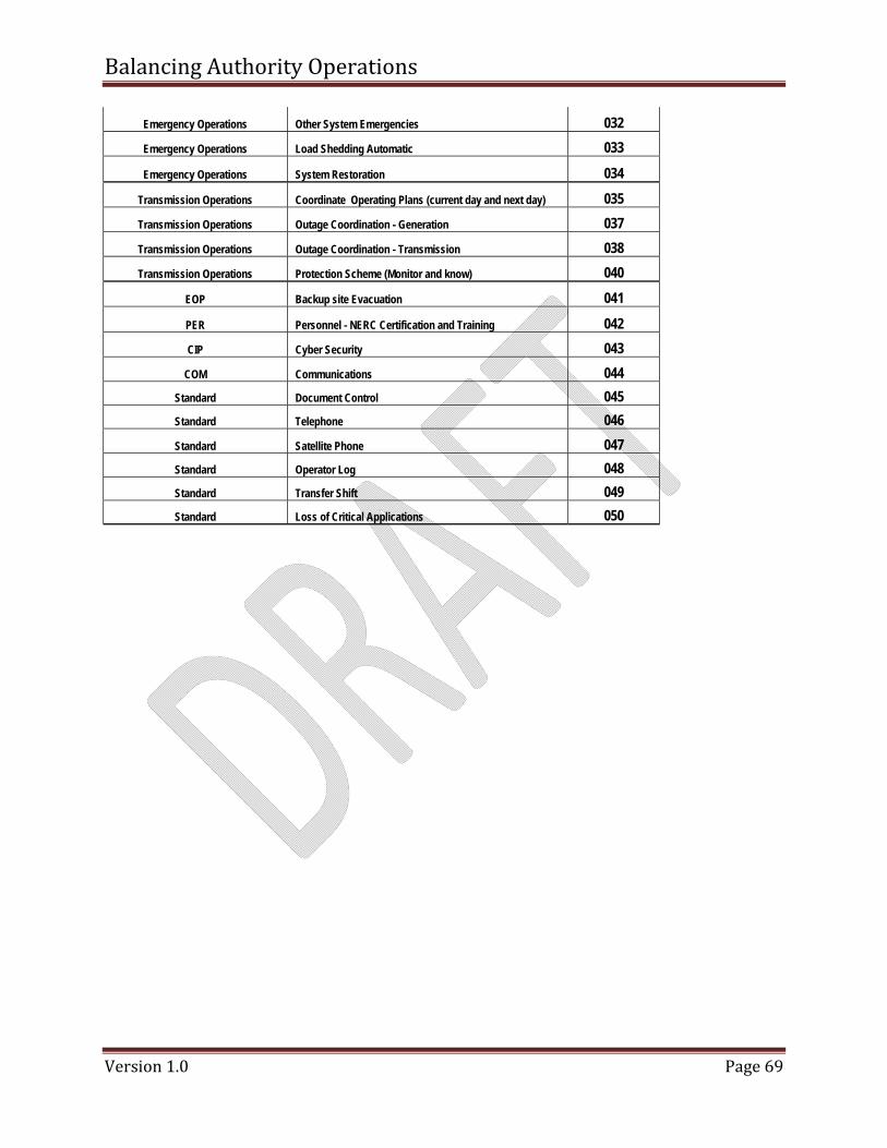
Balancing Authority Operations
Version 1.0 Page 69
Emergency Operations Other System Emergencies 032 Emergency Operations Load Shedding Automatic 033
Emergency Operations System Restoration 034
Transmission Operations Coordinate Operating Plans (current day and next day) 035 Transmission Operations Outage Coordination - Generation 037 Transmission Operations Outage Coordination - Transmission 038 Transmission Operations Protection Scheme (Monitor and know) 040
EOP Backup site Evacuation 041
PER Personnel - NERC Certification and Training 042 CIP Cyber Security 043
COM Communications 044 Standard Document Control 045 Standard Telephone 046 Standard Satellite Phone 047 Standard Operator Log 048 Standard Transfer Shift 049 Standard Loss of Critical Applications 050


![BEN Helps P2P [PROCURE-TO-PAY] Presents “The Procure to Pay Life Cycle” BEN Helps & P2P [PROCURE-TO-PAY] Presents “The Procure to Pay Life Cycle” Last.](https://static.fdocuments.us/doc/165x107/56649d6d5503460f94a4d696/ben-helps-p2p-procure-to-pay-presents-the-procure-to-pay-life-cycle.jpg)


