Balanced Steel Percentage - WEC...
90
Balanced Steel Percentage In this section, an expression is derived for ρb, the percentage of steel required for a balanced design. At ultimate load for such a beam, the concrete will theoretically fail (at a strain of 0.00300), and the steel will simultaneously yield. The neutral axis is located by the triangular strain relationships that follow, noting that Es = 29 × 10⁶ psi for the reinforcing bars: This expression is rearranged and simplified, giving 1
Transcript of Balanced Steel Percentage - WEC...

Balanced Steel PercentageIn this section, an expression is derived for ρb, the percentage of
steel required for a balanced design. At ultimate load for such a beam, the
concrete will theoretically fail (at a strain of 0.00300), and the steel will
simultaneously yield.
The neutral axis is located by the triangular strain relationships
that follow, noting that Es = 29 × 10⁶ psi for the reinforcing bars:
This expression is rearranged and simplified, giving
1

Balanced Steel Percentage
In Section 3.4 of this chapter, an expression was derived for depth
of the compression stress block, a, by equating the values of C and T. This
value can be converted to the neutral axis depth, c, by dividing it by β1:
2

Balanced Steel Percentage
Two expressions are now available for c, and they are equated to
each other and solved for the percentage of steel. This is the balanced
percentage, ρb:
Values of ρb can easily be calculated for different values of f’c and fy and
tabulated for U.S. customary units as shown in Appendix A, Table A.7. For SI
units, it’s Appendix B, Table B.7.
3

Balanced Steel Percentage
Previous codes (1963–1999) limited flexural members to 75% of
the balanced steel ratio, ρb. However, this approach was changed in the
2002 code to the new philosophy explained in Section 3.7, whereby the
member capacity is penalized by reducing the φ factor when the strain in
the reinforcing steel at ultimate is less than 0.005.
4

Example 3.2Determine the ACI design moment capacity, φMn, of the beam shown in Figure 3.8 if f’c = 4000 psi and fy = 60,000 psi.
Solution
5

APPENDIX A
6

Example 3.2Solution
7

Example 3.4Determine the ACI design moment capacity, φMn, for the beam of Figure 3.11 if f’c = 4000 psi and fy = 60,000 psi.
Solution
8

Example 3.4Solution
9

Strength Reduction or φ Factors
10

Load FactorsLoad factors are numbers, almost always larger than 1.0, that are
used to increase the estimated loads applied to structures. They are used
for loads applied to all types of members, not just beams and slabs. The
loads are increased to attempt to account for the uncertainties involved in
estimating their magnitudes. How close can one estimate the largest wind
or seismic loads that will ever be applied to the building that you are now
occupying? How much uncertainty is present in your answer?
it should also be noted that the load factors for dead loads are
much smaller than the ones used for live and environmental loads.
Obviously, the reason is that we can estimate the magnitudes of dead
loads much more accurately than we can the magnitudes of those other
loads.11

Load FactorsIn this regard, you will notice that the magnitudes of loads that
remain in place for long periods of time are much less variable than are
those loads applied for brief periods, such as wind and snow.
Section 9.2 of the code presents the load factors and
combinations that are to be used for reinforced concrete design. The
required strength, U, or the load-carrying ability of a particular reinforced
concrete member, must at least equal the largest value obtained by
substituting into ACI Equations 9-1 to 9-7. The following equations conform
to the requirements of the International Building Code (IBC) as well as to
the values required by ASCE/SEI 7-10.
12

Load FactorsU = 1.4D (ACI Equation 9-1)
U = 1.2D + 1.6L + 0.5(Lr or S or R) (ACI Equation 9-2)
U = 1.2D + 1.6(Lr or S or R) + (L or 0.5W) (ACI Equation 9-3)
U = 1.2D + 1.0W + L + 0.5(Lr or S or R) (ACI Equation 9-4)
U = 1.2D + 1.0E + L + 0.2S (ACI Equation 9-5)
U = 0.9D + 1.0W (ACI Equation 9-6)
U = 0.9D + 1.0E (ACI Equation 9-7)
In the preceding expressions, the following values are used:
U = the design or ultimate load the structure needs to be able to resist
D = dead load
L = live load
13

Load FactorsLr = roof live load
S = snow load
R = rain load
W = wind load
E = seismic or earthquake load effects
When impact effects need to be considered, they should be included
with the live loads as per ACI Section 9.2.2. Such situations occur when those
loads are quickly applied, as they are for parking garages, elevators, loading
docks, cranes, and others.
14

Load FactorsThe load combinations presented in ACI Equations 9-6 and 9-7
contain a 0.9D value. This 0.9 factor accounts for cases where larger dead
loads tend to reduce the effects of other loads. One obvious example of such a
situation may occur in tall buildings that are subject to lateral wind and
seismic forces where overturning may be a possibility. As a result, the dead
loads are reduced by 10% to take into account situations where they may have
been overestimated.The reader must realize that the sizes of the load factors do not vary
in relation to the seriousness of failure. You may think that larger load factors
should be used for hospitals or high rise buildings than for cattle barns, but
such is not the case.
15

Load FactorsThe load factors were developed on the assumption that designers
would consider the seriousness of possible failure in specifying the magnitude
of their service loads. Furthermore, the ACI load factors are minimum values,
and designers are perfectly free to use larger factors as they desire. The
magnitude of wind loads and seismic loads, however, reflects the importance
of the structure. For example, in ASCE-7 a hospital must be designed for an
earthquake load 50% larger than a comparable building with less serious
consequences of failure.For some special situations, ACI Section 9.2 permits reductions in the
specified load factors. These situations are as follows:
a. In ACI Equations 9-3 to 9-5, the factor used for live loads may be
reduced to 0.5 except for garages, areas used for public assembly, and
all areas where the live loads exceed 100 psf.16

Load Factorsb. If the load W is based on service-level wind loads, replace 1.0W in ACI
Equations 9-4 and 9-6 with 1.6W. Also, replace 0.5W with 0.8W in ACI
Equation 9-3.
c. Frequently, building codes and design load references convert seismic
loads to strength level values (i.e., in effect they have already been
multiplied by a load factor). This is the situation assumed in ACI
Equations 9-5 and 9-7. If, however, service-load seismic forces are
specified, it will be necessary to replace 1.0E with 1.4E in these two
equations.
d. Self-restraining effects, T, in reinforced concrete structures include
the effects of temperature, creep, shrinkage, and differential
settlement. In some cases, the effects can be additive. For example,
17

Load Factorscreep, shrinkage, and reduction in temperature all cause a reduction
of concrete volume. Often such effects can be reduced or eliminated
by proper use of control joints.
e. Fluid loads, F, resulting from the weight and pressure of fluids shall
be included with the same load factor as D in ACI Equations 9-5
through 9-7.
f. Where soil loads, H, are present, they must be added to the load
combinations in accordance with one of the following:
• where H acts alone or adds to the effects of other loads, it shall
be included with a load factor of 1.6;
• where the effect of H is permanent and counteracts the effects of
other loads, it shall be included with a load factor of 0.9;18

Load Factors• where the effect of H is not permanent but, when present,
counteracts the effects of other loads, H shall not be included.
Next example presents the calculation of factored loads for a reinforced
concrete column using the ACI load combinations. The largest value obtained
is referred to as the critical or governing load combination and is the value to
be used in design. Notice that the values of the wind and seismic loads can be
different depending on the direction of those forces, and it may be possible for
the sign of those loads to be different (i.e., compression or tension). This is the
situation assumed to exist in the column of this example.
19

Load Factors
The compression gravity axial loads for a building column have been estimated
with the following results: D = 150 k; live load from roof, Lr = 60 k; and live
loads from floors, L = 300 k. Compression wind, W = 70 k; tensile wind, W
= 60 k; seismic compression load = 50 k; and tensile seismic load = 40 k.
Determine the critical design load using the ACI load combinations.
Example 4.1
Solution
20

Load FactorsExample 4.1Solution
For most of the example problems, in the interest of reducing the number
of computations, only dead and live loads are specified. As a result, the only
load factor combination usually applied herein is the one presented by ACI
Equation 9-2. Occasionally, when the dead load is quite large compared to
the live load, it is also necessary to consider Equation 9-1.
21

Τιλλ νεξτ τιµε ωε µεετ!
22

Design of Rectangular BeamsBefore the design of an actual beam is attempted, several miscellaneous
topics need to be discussed. These include the following:
1. Beam proportions. Unless architectural or other requirements dictate
the proportions of reinforced concrete beams, the most economical
beam sections are usually obtained for shorter beams (up to 20 ft or
25 ft in length), when the ratio of d to b is in the range of 1½ to 2. For
longer spans, better economy is usually obtained if deep, narrow
sections are used. The depths may be as large as three or four times
the widths. However, today’s reinforced concrete designer is often
confronted with the need to keep members rather shallow to reduce
floor heights. As a result, wider and shallower beams are used more
frequently than in the past. You will notice that the overall beam
23

Design of Rectangular Beamsdimensions are selected to whole inches. This is done for simplicity in
constructing forms or for the rental of forms, which are usually
available in 1-in. or 2-in. increments. Furthermore, beam widths are
often selected in multiples of 2 in. or 3 in.
2. Deflections. Considerable space is devoted in Chapter 6 to the topic
of deflections in reinforced concrete members subjected to bending.
However, the ACI Code in its Table 9.5(a) provides minimum
thicknesses of beams and one-way slabs for which such deflection
calculations are not required. These values are shown in the next
Table. The purpose of such limitations is to prevent deflections of
such magnitudes as would interfere with the use of or cause injury to
the structure. If deflections are computed for members of lesser
thicknesses than those listed in the table and are found to be24

Design of Rectangular Beamssatisfactory, it is not necessary to abide by the thickness rules. For
simply supported slabs, normal-weight concrete, and Grade 60 steel,
the minimum depth given when deflections are not computed equals
l/20, where l is the span length of the slab. For concrete of other
weights and for steel of different yield strengths, the minimum depths
required by the ACI Code are somewhat revised, as indicated in the
footnotes to Table 4.1. The ACI does not specify changes in the table
for concretes weighing between 120 pcf and 145 pcf because
substitution into the correction expression given yields correction
factors almost equal to 1.0. The minimum thicknesses provided apply
only to members that are not supporting or attached to partitions or
other construction likely to be damaged by large deflections.
25

Design of Rectangular Beams
26

Design of Rectangular Beams3. Estimated beam weight. The weight of the beam to be selected must
be included in the calculation of the bending moment to be resisted,
because the beam must support itself as well as the external loads.
The weight estimates for the beams selected in this text are generally
very close. Following the same procedures, however, you can do a
little figuring on the side and make a very reasonable estimate. For
instance, calculate the moment due to the external loads only, select
a beam size, and calculate its weight. From this beam size, one
should be able to make a very good estimate of the weight of the
final beam section.
27

Design of Rectangular BeamsAnother practical method for estimating beam sizes is to assume a
minimum overall depth, h, equal to the minimum depth specified by Table 4.1
[ACI-318-11, Table 9.5(a)] if deflections are not to be calculated. The ACI
minimum for the beam in question may be determined by referring to Table
4.1. Then the beam width can be roughly estimated equal to about one-half of
the assumed value of h and the weight of this estimated beam calculated=
bh/144 times the concrete weight per cubic foot. Because concrete weighs
approximately 150 pcf (if the weight of steel is included), a quick-and-dirty
calculation of self-weight is simply b × h because the concrete weight
approximately cancels the 144 conversion factor.
28

Design of Rectangular BeamsAfter Mu is determined for all of the loads, including the estimated
beam weight, the section is selected. If the dimensions of this section are
significantly different from those initially assumed, it will be necessary to
recalculate the weight and Mu and repeat the beam selection. At this point you
may very logically ask, “What’s a significant change?” Well, you must realize
that we are not interested academically in how close our estimated weight is
to the final weight, but rather we are extremely interested in how close our
calculated Mu is to the actual Mu. In other words, our estimated weight may be
considerably in error, but if it doesn’t affect Mu by more than say 1% or 1½ %,
forget it.
29

Design of Rectangular Beams4. Selection of bars. After the required reinforcing area is calculated,
Appendix A, Table A.4 is used to select bars that provide the
necessary area. For the usual situations, bars of sizes #11 and smaller
are practical. It is usually convenient to use bars of one size only in a
beam, although occasionally two sizes will be used. Bars for
compression steel and stirrups are usually a different size, however.
Otherwise the ironworkers may become confused.
5. Cover. The reinforcing for concrete members must be protected from
the surrounding environment; that is, fire and corrosion protection
need to be provided. To do this, the reinforcing is located at certain
minimum distances from the surface of the concrete so that a
protective layer of concrete, called cover, is provided. In addition, the
30
Design of Rectangular Beamscover improves the bond between the concrete and the steel. In
Section 7.7 of the ACI Code, specified cover is given for reinforcing
bars under different conditions. Values are given for reinforced
concrete beams, columns, and slabs; for cast-in-place members; for
precast members; for pre-stressed members; for members exposed
to earth and weather; for members not so exposed; and so on. The
concrete for members that are to be exposed to deicing salts,
brackish water, seawater, or spray from these sources must be
especially proportioned to satisfy the exposure requirements of
Chapter 4 of the code. These requirements pertain to air
entrainment, water–cement ratios, cement types, concrete strength,
and so on.
31

Design of Rectangular BeamsThe beams designs in general are assumed to be located inside a
building and thus protected from the weather. For this case, the code requires
a minimum cover of 1½ in. of concrete outside of any reinforcement.
In Chapter 8, vertical stirrups are used in most beams for shear
reinforcing. A sketch of a stirrup is shown in the beam in next figure. The
minimum stirrup diameter (ds) that the code permits us to use is ⅜ in. when
the longitudinal bars are #10 or smaller; for #11 and larger bars, the minimum
stirrup diameter is ½ in. The minimum inside radius of the 90◦ stirrup bent
around the outside longitudinal bars is two times the stirrup diameter (2ds). As
a result, when the longitudinal bars are #14 or smaller, there will be a gap
between the bars and the stirrups, as shown in the figure.
32

Design of Rectangular Beams
33

Design of Rectangular Beams
This is based on the assumption that each outside longitudinal bar is
centered over the horizontal point of tangency of the stirrup corner bend. For
#18 bars, however, the half-bar diameter is larger than 2ds and controls.
For the beam of Figure 4.1 it is assumed that 1.50-in. clear cover, #3
stirrups, and #10 longitudinal bars are used. The minimum horizontal distance
from the center of the outside longitudinal bars to the edge of the concrete
can be determined as follows:
34

Design of Rectangular BeamsThe minimum cover required for concrete cast against earth, as in a
footing, is 3 in., and for concrete not cast against the earth but later exposed
to it, as by backfill, 2 in. Precast and pre-stressed concrete or other concrete
cast under plant control conditions requires less cover, as described in
Sections 7.7.2 and 7.7.3 of the ACI Code.Notice the two #4 bars called hangers placed in the compression side
of this beam. Their purpose is to provide support for the stirrups and to hold
the stirrups in position. If concrete members are exposed to very harsh
surroundings, such as deicing salts, smoke, or acid vapors, the cover should be
increased above these minimums.
35

Design of Rectangular Beams
36
Design of Rectangular Beams6. Minimum spacing of bars. The code (7.6) states that the clear
distance between parallel bars cannot be less than 1 in. or less
than the nominal bar diameter. If the bars are placed in more than
one layer, those in the upper layers are required to be placed directly
over the ones in the lower layers, and the clear distance between the
layers must be not less than 1 in.
A major purpose of these requirements is to enable the concrete to pass
between the bars. The ACI Code further relates the spacing of the bars to the
maximum aggregate sizes for the same purpose. In the code Section 3.3.2,
maximum permissible aggregate sizes are limited to the smallest of
(a) one-fifth of the narrowest distance between side forms,
(b) one-third of slab depths, and
(c) three-fourths of the minimum clear spacing between bars.37

Design of Rectangular BeamsA reinforcing bar must extend an appreciable length in both
directions from its point of highest stress in order to develop its stress by
bonding to the concrete. The shortest length in which a bar’s stress can be
increased from 0 to fy is called its development length.
If the distance from the end of a bar to a point where it theoretically
has a stress equal to fy is less than its required development length, the bar
may very well pull loose from the concrete. Development lengths will be
discussed in detail later. Required development lengths for reinforcing bars
vary appreciably with their spacing and their cover. As a result, it is sometimes
wise to use greater cover and larger bar spacing than the specified minimum
values in order to reduce development lengths.
38

Design of Rectangular BeamsWhen selecting the actual bar spacing, the designer will comply with
the preceding code requirements and, in addition, will give spacing and other
dimensions in inches and fractions, not in decimals. The workers in the field
are accustomed to working with fractions and would be confused by a spacing
of bars such as 3 at 1.45 in. The designer should always strive for simple
spacing, for such dimensions will lead to better economy.
Each time a beam is designed, it is necessary to select the spacing
and arrangement of the bars. To simplify these calculations, Appendix A, Table
A.5 is given. Corresponding information is provided in SI units in Appendix B,
Table B.5. These tables show the minimum beam widths required for different
numbers of bars. The values given are based on the assumptions that ⅜ -in.
39

Design of Rectangular Beamsstirrups and 1½ -in. cover are required except for #18 bars, where the stirrup
diameter is ½ in. If three #10 bars are required, it can be seen from the table
that a minimum beam width of 10.4 in. (say 11 in.) is required.
This value can be checked as follows, noting that 2ds is the radius of
bend of the bar, and the minimum clear spacing between bars in this case is
db:
40

APPENDIX A
41

Beam Design ExamplesNext example illustrates the design of a simple span rectangular beam. For this
introductory example, approximate dimensions are assumed for the beam
cross section. The depth, h, is assumed to equal about one-tenth of the beam
span, while its width, b, is assumed to equal about ½ h. Next the percentage of
reinforcing needed is determined with the equation derived in Section 3.4,
and reinforcing bars are selected to satisfy that percentage. Finally, φMn is
calculated for the final design.
42

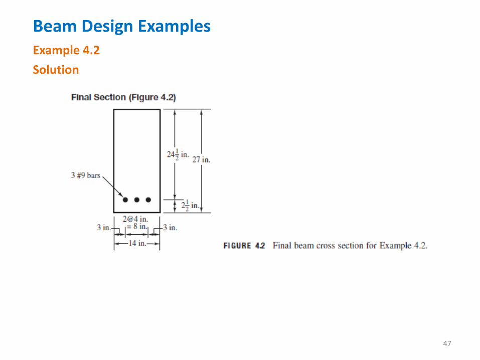
Beam Design ExamplesExample 4.2
Solution
43

Beam Design ExamplesExample 4.2Solution
44

Beam Design ExamplesExample 4.2SolutionAppendix A.5 indicates a minimum beam width of 9.8 in. for interior exposure forthree #9 bars. If five #7 bars had been selected, a minimum width of 12.8 in. wouldbe required. Either choice would be acceptable since the beam width of 14 in.exceeds either requirement. If we had selected a beam width of 12 in. earlier in thedesign process, we might have been limited to the larger #9 bars because of thisminimum beam width requirement.
45

APPENDIX A
46
Beam Design ExamplesExample 4.2Solution
47

Beam Design ExamplesUse of Graphs and Tables
The value of ρ, determined by substituting into that long and
tedious equation, can be directly selected from Appendix A, Table A.13.
We enter that table with the Mu/φbd² value previously calculated in the
example, and we read a value of ρ between 0.0084 and 0.0085.
Interpolation can be used to find the actual value of 0.00842, but such
accuracy is not really necessary. It is conservative to use the higher value
(0.0085) to calculate the steel area.
50

Beam Design ExamplesThrough quite a few decades of reinforced concrete design
experience, it has been found that if steel percentages are kept fairly
small, say roughly 0.18f’c/fy or perhaps 0.375ρb, beam cross sections will
be sufficiently large so that deflections will seldom be a problem. As the
areas of steel required will be fairly small, there will be little problem
fitting them into beams without crowding.If these relatively small percentages of steel are used, there will
be little difficulty in placing the bars and in getting the concrete between
them. Of course, from the standpoint of deflection, higher percentages of
steel, and thus smaller beams, can be used for short spans where
deflections present no problem.
55

Beam Design ExamplesWhatever steel percentages are used, the resulting members will
have to be carefully checked for deflections, particularly for long-span
beams, cantilever beams, and shallow beams and slabs. Of course, such
deflection checks are not required if the minimum depths specified in
Table 4.1 of this chapter are met.
Another reason for using smaller percentages of steel is given in
ACI Section 8.4, where a plastic redistribution of moments (a subject to be
discussed in Chapter 14) is permitted in continuous members whose ϵt
values are 0.0075 or greater. Such tensile strains will occur when smaller
percentages of steel are used. For the several reasons mentioned here,
structural designers believe that keeping steel percentages fairly low will
result in good economy.
56

Beam Design ExamplesExample 4.4
Solution
57

APPENDIX A
Cont… 58

APPENDIX A
59

Beam Design ExamplesExample 4.4Solution
60

Beam Design ExamplesExample 4.4Solution
61

Beam Design ExamplesExample 4.4Solution
62

TABLES A-12fy = 60,000 PSI; f’c = 3000 PSI—U.S. Customary Units

TABLES A-12 (Cont’d)

Τιλλ νεξτ τιµε ωε µεετ!
65

Miscellaneous Beam ConsiderationsThis section introduces two general limitations relating to beam
design: lateral bracing and deep beams.
Lateral Support
It is unlikely that laterally un-braced reinforced concrete beams of any
normal proportions will buckle laterally, even if they are deep and narrow,
unless they are subject to appreciable lateral torsion. As a result, the ACI Code
(10.4.1) states that lateral bracing for a beam is not required closer than 50
times the least width, b, of the compression flange or face. Should appreciable
torsion be present, however, it must be considered in determining the
maximum spacing for lateral support.
66

Miscellaneous Beam ConsiderationsSkin Reinforcement for Deep Beams
Beams with web depths that exceed 3 ft have a tendency to develop
excessively wide cracks in the upper parts of their tension zones. To reduce
these cracks, it is necessary to add some additional longitudinal reinforcing in
the zone of flexural tension near the vertical side faces of their webs, as shown
in Figure 4.4. The code (10.6.7) states that additional skin reinforcement must
be uniformly distributed along both side faces of members with h>36 in. for
distances equal to h/2 nearest the flexural reinforcing.
The spacing, s, between this skin reinforcement shall be as provided
in ACI 10.6.4. These additional bars may be used in computing the bending
strengths of members only if appropriate strains for their positions relative to
neutral axes are used to determine bar stresses.
67

Miscellaneous Beam ConsiderationsSkin Reinforcement for Deep Beams
The total area of the skin reinforcement in both side faces of the
beam does not have to exceed one-half of the required bending tensile
reinforcement in the beam. The ACI does not specify the actual area of skin
reinforcing; it merely states that some additional reinforcement should be
placed near the vertical faces of the tension zone to prevent cracking in the
beam webs.
Some special requirements must be considered relating to shear in
deep beams, as described in the ACI Code (11.7) and in Section 8.14 of this
text. Should these latter provisions require more reinforcing than required by
ACI Section 10.6.7, the larger values will govern.
68

Miscellaneous Beam ConsiderationsSkin Reinforcement for Deep Beams
For a beam designed in SI units with an effective depth > 1 m,
additional skin reinforcement must be determined with the following
expression, in which Ask is the area of skin reinforcement per meter of height
on each side of the beam:
Its maximum spacing may not exceed d/6 on 300 mm or
1000Ab/(d−750).
69

Miscellaneous Beam ConsiderationsOther Items
The next four chapters of this book are devoted to several other
important items relating to beams. These include different shaped beams,
compression reinforcing, cracks, bar development lengths, and shear.
From the standpoints of economy and appearance, only a few
different sizes of beams should be used in a particular floor system. Such a
practice will save appreciable amounts of money by simplifying the formwork
and at the same time will provide a floor system that has a more uniform and
attractive appearance. If a group of college students studying the subject of
reinforced concrete were to design a floor system and then compare their
work with a design of the same floor system made by an experienced
structural designer.
Further Notes on Beam Sizes
70

Miscellaneous Beam Considerations
The odds are that the major difference between the two designs
would be in the number of beam sizes. The practicing designer would probably
use only a few different sizes, whereas the average student would probably
use a larger number.
The designer would probably examine the building layout to decide
where to place the beams and then would make the beam subject to the
largest bending moment as small as practically possible (i.e., with a fairly high
percentage of reinforcing). Then he or she would proportion as many as
possible of the other similar beams with the same outside dimensions. The
reinforcing percentages of these latter beams might vary quite a bit because of
their different moments.
Further Notes on Beam Sizes
71

Determining Steel Area When Beam Dimensions Are PredeterminedSometimes the external dimensions of a beam are predetermined by
factors other than moments and shears. The depth of a member may have
been selected on the basis of the minimum thickness requirements discussed
in Section 4.2 for deflections. The size of a whole group of beams may have
been selected to simplify the formwork, as discussed in Section 4.4. Finally, a
specific size may have been chosen for architectural reasons. Next we briefly
mention three methods for computing the reinforcing required. Example 4.5
illustrates the application of each of these methods.
72

Determining Steel Area When Beam Dimensions Are Predetermined
The value of Mu/φbd² can be computed, and ρ can be selected from
the tables. For most situations this is the quickest and most practical method.
The tables given in Appendices A and B of this text apply only to tensilely
reinforced rectangular sections. Furthermore, we must remember to check φ
values.
Appendix Tables
Use of ρ Formula
The following equation was previously developed in Section 3.4 for
rectangular sections.
73

Determining Steel Area When Beam Dimensions Are Predetermined
A value of a can be assumed, the value of As computed, the value of a
determined for that value of As, another value of a calculated, and so on.
Alternatively, a value of the lever arm from C to T (it’s d−a/2 for rectangular
sections) can be estimated and used in the trial-and error procedure. This
method is a general one that will work for all cross sections with tensile
reinforcing. It is particularly useful for T beams, as will be illustrated in the
next chapter.
Trial-and-Error (Iterative) Method
74

Determining Steel Area When Beam Dimensions Are PredeterminedExample 4.5The dimensions of the beam shown in Figure 4.5 have been selected for architectural
reasons. Determine the reinforcing steel area by each of the methods described in this
section.
Solution
75

Determining Steel Area When Beam Dimensions Are PredeterminedExample 4.5Solution
Trial-and-Error (Iterative) Method
Here it is necessary to estimate the value of a. The student probably has no idea of a
reasonable value for this quantity, but the accuracy of the estimate is not a matter of
importance. He or she can assume some value probably considerably less than d/2
and then compute d−a/2 and As. With this value of As, a new value of a can be
computed and the cycle repeated. After two or three cycles, a very good value of a
will be obtained.
76

Determining Steel Area When Beam Dimensions Are PredeterminedExample 4.5Solution
Trial-and-Error (Iterative) Method
77

Bundled Bars
Sometimes when large amounts of steel reinforcing are required in
a beam or column, it is very difficult to fit all the bars in the cross section. For
such situations, groups of parallel bars may be bundled together. Up to four
bars can be bundled, provided they are enclosed by stirrups or ties. The ACI
Code (7.6.6.3) states that bars larger than #11 shall not be bundled in beams
or girders. This is primarily because of crack control problems, a subject
discussed in Chapter 6 of this text. That is, if the ACI crack control provisions
are to be met, bars larger than #11 cannot practically be used. The AASHTO
permits the use of two-, three-, and four-bar bundles for bars up through the
#11 size. For bars larger than #11, however, AASHTO limits the bundles to
two bars (AASHTO Sections 8.21.5 ASD and 5.10.3.1.5 strength design).
78

Bundled BarsTypical configurations for two-, three-, and four-bar bundles are
shown in Figure 4.6. When bundles of more than one bar deep vertically are
used in the plane of bending, they may not practically be hooked or bent as a
unit. If end hooks are required, it is preferable to stagger the hooks of the
individual bars within the bundle.
Although the ACI permits the use of bundled bars, their use in the
tension areas of beams may very well be counterproductive because of the
other applicable code restrictions that are brought into play as a result of
their use. When spacing limitations and cover requirements are based on bar
sizes, the bundled bars may be treated as a single bar for computation
purposes; the diameter of the fictitious bar is to be calculated from the total
equivalent area of the group.
79

Bundled Bars
When individual bars in a bundle are cut off within the span of
beams or girders, they should terminate at different points. The code
(7.6.6.4) requires that there be a stagger of at least 40 bar diameters.
80

One-Way SlabsReinforced concrete slabs are large flat plates that are supported by
reinforced concrete beams, walls, or columns; by masonry walls; by
structural steel beams or columns; or by the ground. If they are supported on
two opposite sides only, they are referred to as one-way slabs because the
bending is in one direction only—that is, perpendicular to the supported
edges. Should the slab be supported by beams on all four edges, it is referred
to as a two-way slab because the bending is in both directions. Actually, if a
rectangular slab is supported on all four sides, but the long side is two or
more times as long as the short side, the slab will, for all practical purposes,
act as a one-way slab, with bending primarily occurring in the short direction.
Such slabs are designed as one-way slabs. You can easily verify these bending
moment ideas by supporting a sheet of paper on two opposite sides or on
four sides with the support situation described.81

One-Way SlabsThis section is concerned with one-way slabs; two-way slabs are
considered separately. It should be realized that a large percentage of
reinforced concrete slabs fall into the one-way class.
A one-way slab is assumed to be a rectangular beam with a large
ratio of width to depth. Normally, a 12-in.-wide piece of such a slab is
designed as a beam (see Figure 4.7), the slab being assumed to consist of a
series of such beams side by side. The method of analysis is somewhat
conservative because of the lateral restraint provided by the adjacent parts
of the slab. Normally, a beam will tend to expand laterally somewhat as it
bends, but this tendency to expand by each of the 12-in. strips is resisted by
the adjacent 12-in.-wide strips, which tend to expand also. In other words,
Poisson’s ratio is assumed to be zero
82

One-Way SlabsActually, the lateral expansion tendency results in a very slight
stiffening of the beam strips, which is neglected in the design procedure
used here.The 12-in.-wide beam is quite convenient when thinking of the load
calculations because loads are normally specified as so many pounds per
square foot, and thus the load carried per foot of length of the 12-in.-wide
beam is the load supported per square foot by the slab. The load supported
by the one-way slab, including its own weight, is transferred to the members
supporting the edges of the slab. Obviously, the reinforcing for flexure is
placed perpendicular to these supports—that is, parallel to the long
direction of the 12-in.-wide beams. This flexural reinforcing may not be
spaced farther on center than three times the slab thickness, or 18 in.,
according to the ACI Code (7.6.5). Of course, there will be some reinforcing
placed in the other direction to resist shrinkage and temperature stresses.83

One-Way Slabs
The thickness required for a particular one-way slab depends on the
bending, the deflection, and shear requirements. As described in Section 4.2,
the ACI Code (9.5.2.1) provides certain span/depth limitations for concrete
flexural members where deflections are not calculated.
84

One-Way SlabsBecause of the quantities of concrete involved in floor slabs, their
depths are rounded off to closer values than are used for beam depths. Slab
thicknesses are usually rounded off to the nearest ¼ in. on the high side for
slabs of 6 in. or less in thickness and to the nearest ½ in. on the high side for
slabs thicker than 6 in.
As concrete hardens, it shrinks. In addition, temperature changes
occur that cause expansion and contraction of the concrete. When cooling
occurs, the shrinkage effect and the shortening due to cooling add together.
The code (7.12) states that shrinkage and temperature reinforcement must be
provided in a direction perpendicular to the main reinforcement for one-way
slabs. (For two-way slabs, reinforcement is provided in both directions for
bending.)
85

One-Way Slabs
The code states that for Grade 40 or 50 deformed bars, the minimum
percentage of this steel is 0.002 times the gross cross-sectional area of the
slab. Notice that the gross cross-sectional area is bh (where h is the slab
thickness). The code (7.12.2.2) states that shrinkage and temperature
reinforcement may not be spaced farther apart than five times the slab
thickness, or 18 in. When Grade 60 deformed bars or welded wire fabric is
used, the minimum area is 0.0018bh. For slabs with fy > 60,000 psi, the
minimum value is (0.0018 × 60,000)/fy ≥ 0.0014.
86

One-Way Slabs
Should structural walls or large columns provide appreciable
resistance to shrinkage and temperature movements, it may very well be
necessary to increase the minimum amounts listed.Shrinkage and temperature steel serves as mat steel in that it is tied
perpendicular to the main flexural reinforcing and holds it firmly in place as a
mat. This steel also helps to distribute concentrated loads transversely in the
slab. (In a similar manner, the AASHTO gives minimum permissible amounts of
reinforcing in slabs transverse to the main flexural reinforcing for lateral
distribution of wheel loads.)
87

One-Way SlabsAreas of steel are often determined for 1-ft widths of reinforced
concrete slabs, footings, and walls. A table of areas of bars in slabs such as
Appendix A, Table A.6 is very useful in such cases for selecting the specific bars
to be used. A brief explanation of the preparation of this table is provided
here.For a 1 ft width of concrete, the total steel area obviously equals the
total or average number of bars in a 1-ft width times the cross-sectional area
of one bar. This can be expressed as (12 in./bar spacing c. to c.)(area of 1 bar).
Some examples follow, and the values obtained can be checked in the table.
Understanding these calculations enables one to expand the table as desired.
88

One-Way SlabsExample 4.6 illustrates the design of a one-way slab. It will be noted
that the code (7.7.1.c) cover requirement for reinforcement in slabs (#11 and
smaller bars) is ¾ in. clear, unless corrosion or fire protection requirements are
more severe.
89

One-Way Slabs
Design a one-way slab for the inside of a building using the span,loads, and other data given in Figure 4.8. Normal-weight aggregate concrete isspecified with a density of 145 pcf.
Example 4.6
Solution
90

One-Way SlabsExample 4.6
Solution
91

One-Way SlabsExample 4.6
SolutionThe #4 bars are placed below the #3 bars in this case. The #4 bars are the primary
flexural reinforcing, and the value of d is based on this assumption. The #3 bars are for
temperature and shrinkage control, and their depth within the slab is not as critical.
92

One-Way Slabs
The designers of reinforced concrete structures must be very careful
to comply with building code requirements for fire resistance. If the
applicable code requires a certain fire resistance rating for floor systems, that
requirement may very well cause the designer to use thicker slabs than might
otherwise be required to meet the ACI strength design requirements. In other
words, the designer of a building should study carefully the fire resistance
provisions of the governing building code before proceeding with the design.
Section 7.7.8 of ACI 318-11 includes such a requirement.
93

Cantilever Beams and Continuous BeamsCantilever beams supporting gravity loads are subject to negative
moments throughout their lengths. As a result, their reinforcement is placed
in their top or tensile sides, as shown in Figures 4.9 and 4.10(a). The reader
will note that for such members the maximum moments occur at the faces
of the fixed supports. As a result, the largest amounts of reinforcing are
required at those points. You should also note that the bars cannot be
stopped at the support faces. They must be extended or anchored in the
concrete beyond the support face. We will later call this development length.
The development length does not have to be straight as shown in the figure,
because the bars may be hooked at 90◦ or 180◦. Development lengths and
hooked bars are discussed in depth in Chapter 7.
94

Cantilever Beams and Continuous BeamsUp to this point, only statically determinate members have been
considered. The very common situation, however, is for beams and slabs to
be continuous over several supports, as shown in Figure 4.10. Because
reinforcing is needed on the tensile sides of the beams, we will place it in the
bottoms when we have positive moments and in the tops when we have
negative moments. There are several ways in which the reinforcing bars can
be arranged to resist the positive and negative moments in continuous
members. One possible arrangement is shown in Figure 4.10(a). These
members, including bar arrangements, are discussed in detail in Chapter 14.
95

Cantilever Beams and Continuous Beams
96