Baja Saeindia 2011 Rulebook
81
Go Green!!! BAJA SAE® SERIES BAJA SAEINDIA 2011 unleash the spirit Rule Book Version 1_May’2010 C/O SAE‐INDIA, NATRIP
-
Upload
alankrit-shukla -
Category
Documents
-
view
228 -
download
0
description
rulebook
Transcript of Baja Saeindia 2011 Rulebook

Go Green!!!
BAJA SAE® SERIES
BAJA SAEINDIA 2011 unleash the spirit
Rule Book Version 1_May’2010
C/O SAE‐INDIA, NATRIP
2 BAJA SAE INDIA® 2011 Rule Book
www.bajasaeindia.org 2 | P a g e
www.saenis.org/virtualbaja
Index 11.Overview.............................................................................................................................................. 8 11.1 Baja SAE India Program Objective............................................................................................................. 8 11.2 Competition Goals..................................................................................................................................... 8 11.3 The Baja SAE Series................................................................................................................................... 8 11.4 Official Announcements and Competition Information............................................................................ 9 12. Baja SAE Rules and Organizer Authority.............................................................................................. 9 12.1 Rules Authority.......................................................................................................................................... 9 12.2 Rules Validity............................................................................................................................................. 9 12.3 Rules Compliance...................................................................................................................................... 9 12.4 Understanding the Rules........................................................................................................................... 10 12.5 Participating in the Competition............................................................................................................... 10 12.6 Violations of Intent.................................................................................................................................... 10 12.7 Right to Impound....................................................................................................................................... 10 12.8 General Authority...................................................................................................................................... 10 13.Eligibility.............................................................................................................................................. 10 13.1 Individual Participant Requirements......................................................................................................... 10 13.1.1 Student Status........................................................................................................................................ 11 13.1.2 Society Membership............................................................................................................................... 11 13.1.3 Age............................................................................................................................ 11 13.1.4 Driver’s License......................................................................................................................... 11 13.1.5 Liability Waiver and Insurance.................................................................................................... 11 13.1.6 Online Registration Requirements................................................................……………………………………… 11 13.1.7 Onsite Registration – Document Copies required……………………………………………………………………………….11 13.2 Faculty Advisor.......................................................................................................................... 12 14. Eligibility –Vehicles..................................................................................................................... 12 14.1 Student Created................................................................................................................................... 12 14.2 Professional Fabrication Limits.................................................................................. 12 14.3 Kit Vehicles – Prohibited............................................................................................... 12 14.4 Prefabricated Subassemblies................................................................................................................ 12 14.5 Top Ten Teams – Design Comparison Requirement.................................................................................. 12 14.6 Redesign/Design Comparison Document............................................................................. 13 14.7 Duplicate Designs.......................................................................................................... 13 15. Registration..................................................................................................................................... 13 15.1 Maximum Entries per University...................................................................................................... 13 15.2 Registration Deadline............................................................................................................................... 13 20. General Design Requirements.......................................................................................................... 14 20.1 Vehicle Design Objective........................................................................................................................... 14 20.2 Vehicle Configuration................................................................................................................................ 14 20.2.1 Maximum Vehicle Dimensions.............................................................................................................. 14 20.3 All‐Terrain Capability............................................................................................................................... 14 21. Required Engine................................................................................................................................. 14 21.1 Engine Eligibility....................................................................................................................................... 15 21.2 Eligible Teams – Receiving New Engines................................................................................................. 15 21.2.1 Engine Shipment outside the U.S. & Canada........................................................................................ 15 21.3 Purchasing of Additional Briggs & Stratton Engines.............................................................................. 15 21.4 Engine Requirement and Restrictions....................................................................................................... 15 21.4.1 Replacement Parts............................................................................................................................. 15
3 BAJA SAE INDIA® 2011 Rule Book
www.bajasaeindia.org 3 | P a g e
www.saenis.org/virtualbaja
21.4.2 Piston Rings............................................................................................................................................ 15 21.4.3 Intake Ports........................................................................................................................................ 15 21.4.4 Valves..................................................................................................................................................... 16 21.4.5 Shafts and Rods.................................................................................................................................. 16 21.4.6 Spark Plugs........................................................................................................................................... 16 21.4.7 Flywheel Rotation................................................................................................................................ 16 21.4.8 Carburetor............................................................................................................................................. 16 21.4.9 Air Cleaner.......................................................................................................................................... 16 21.4.10 Exhaust System................................................................................................................................. 16 21.4.11 Starter Rope......................................................................................................................................... 17 21.4.12 Engine Governor................................................................................................................................... 17 21.4.13 Fuel System....................................................................................................................................... 17 21.4.14 Onboard Instrumentation/Data Acquisition....................................................................................... 17 21.4.15Battery Requirements....................................................................................................................... 17 21.4.16 Electronic Controls............................................................................................................................ 18 21.4.17 Storage Energy Devices Used for Propulsion..................................................................................... 18 21.5 Component Failure................................................................................................................................... 18 21.6 Engine Inspection.................................................................................................................................. 18 21.7 Engine Use Restriction............................................................................................................................ 18 22. Transmission ………………………………………………………………………………………………………………………………………19 23. Reverse Light and Alarm......................................................................................................................19 24Towing Hitch Point............................................................................................................................ 19 24.1 Front Hitch Point..................................................................................................................................... 19 24.2 Rear Hitch Plate......................................................................................................................................... 20 24.3 Hitch Plate Requirements – Maximum and Minimum............................................................................ 20 25. Vehicle Identification...................................................................................................................... 20 25.1 Number Assignment................................................................................................................................ 20 25.2 Vehicle Number – Primary Cutout........................................................................................................... 21 25.2.1 Number Location................................................................................................................................. 21 25.2.2 Number Size.......................................................................................................................................... 21 25.3 Vehicle Number – Body.............................................................................................................................22 25.4 College Name.............................................................................................................................................22 25.5 Sponsor Logos........................................................................................................................................... 22 25.5.1 Event sponsor Logos......................................................................................................................... 22 25.5.2 SAE INDIA Logo........................................................................................................................................22... 25.5.3 Sponsor Identification........................................................................................................................... 22 26. Transponders...................................................................................................................................... 22 26.1 Transponders –..................................................................................................................................... 22 26.2 Transponder Requirement...................................................................................................................... 23 26.3 Transponder Mounting........................................................................................................................... 23 26.4 Transponder Black Flag.......................................................................................................................... 23 30. Introduction....................................................................................................................................... 24 30.1 Rules Requirements and Restrictions....................................................................................................... 24 30.1.1 Technical Inspection........................................................................................................................... 24 30.1.2 Required Modifications...................................................................................................................... 24 30.1.3 Unstable Vehicles....................................................................................................................... 24 31. Roll Cage............................................................................................................................................. 24 31.1 Objective................................................................................................................................................... 24 31.2 Roll Cage Requirements.......................................................................................................................... 25

4 BAJA SAE INDIA® 2011 Rule Book
www.bajasaeindia.org 4 | P a g e
www.saenis.org/virtualbaja
31.2.1 Elements of the Roll Cage...................................................................................................................... 25 31.2.2 Rear Roll Hoop (RRH)............................................................................................................................. 26 31.2.3 Rear Roll Hoop Lateral Diagonal Bracing (LBD)................................................................................ 26 31.2.4 Roll Hoop Overhead Members (RHO)................................................................................................. 27 31.2.5 Lower Frame Side Members (LFS)...................................................................................................... 27 31.2.6 Side Impact Members (SIM)................................................................................................................ 28 31.2.7 Front Bracing Members (FBM).......................................................................................................... 28 31.2.8 Roll Hoop Bracing (FAB)....................................................................................................................... 28 31.2.9 RHO /FBM Gusseting ………………………………………………………………………………………………………………………...29 31.2.10 Butt Joints........................................................................................................................................... 29 31.2.11 Weld Confirmation Checks.................................................................................................................. 30 31.2.12 Final Judgment.................................................................................................................................. 31 31.3 Head Restraint......................................................................................................................................... 31 31.4 Driver Head Clearance.............................................................................................................................. 32 31.4.1 Head Clearance – Minimum............................................................................................................... 32 31.5 Roll Cage & Bracing Materials............................................................................................................... 32 31.5.1 Roll Cage Specification Sheet – Required........................................................................................... 33 31.6 Roll Cage Padding.................................................................................................................................. 33 31.7 Sharp Edges on Roll Cage – Prohibited.................................................................................................. 33 31.8 Bolted Roll Cages................................................................................................................................... 33 31.9 Driver Seat……………………………………………………………………………………………………………………………………………33 32. Cockpit........................................................................................................................................... 34 32.1 Design Objective........................................................................................................................................ 34 32.2 Driver Exit Time...................................................................................................................................... 34 32.3 Firewall..................................................................................................................................................... 34 32.3.1 Front or Mid‐engine Cars...................................................................................................................... 34 32.4 Body Panels.............................................................................................................................................. 34 32.5 Belly Pan................................................................................................................................................... 35 32.6 Leg and Foot Shielding............................................................................................................................. 35 32.7 Kill Switches............................................................................................................................................. 35 32.7.1 Kill Switch – Type................................................................................................................................. 35 32.7.2 Kill Switch – Locations and Orientation.............................................................................................. 36 32.7.3 Kill Switch – Wiring.............................................................................................................................. 36 32.8 Fire Extinguisher – Size and Location..................................................................................................... 36 32.9 Throttle.................................................................................................................................................. 36 32.9.1 Throttle Extensions.............................................................................................................................. 36 33. Driver Restraint................................................................................................................................ 37 33.1 Minimum Five Strap System Required.................................................................................................. 37 33.1.1 Release Mechanism............................................................................................................................ 37 33.1.2 Safety Harness Expiration.................................................................................................................... 37 33.2 Shoulder Harness..................................................................................................................................... 37 33.2.1 Vertical Location................................................................................................................................... 37 33.2.2 Horizontal Location............................................................................................................................... 37 33.2.3 Harness Attachment Points................................................................................................................. 38 33.2.4 Redirection of Harness Webbing........................................................................................................ 38 33.3 Lap & Anti‐Submarine Belts................................................................................................................... 38 33.3.1 Specified Lap & Anti‐Submarine Belts Mounting................................................................................ 38 33.4 Belts...................................................................................................................................................... 39 33.5 Arm Restraints....................................................................................................................................... 39 33.5.1 Arm Restraint – Installation............................................................................................................... 39
5 BAJA SAE INDIA® 2011 Rule Book
www.bajasaeindia.org 5 | P a g e
www.saenis.org/virtualbaja
33.5.2 Arm Restraint – Expiration.................................................................................................................. 39 33.5.3 Installations – General.......................................................................................................................... 40 34. Braking System................................................................................................................................... 40 34.1 Foot Brake............................................................................................................................................ 40 34.2 Independent Brake Circuits.................................................................................................................... 40 34.3 Brake Light........................................................................................................................................... 40 34.4 Brake(s) Location.......................................................................................................................... 40 34.5 Cutting Brakes....................................................................................................................................... 40 35. Fuel System and Fuel................................................................................................................. 40 35.1 System Location...................................................................................................................................... 40 35.1.1 Removable Fuel Tank.................................................................................................... 41 35.2 Fuel Tank............................................................................................................................................... 41 35.3 Fuel Lines................................................................................................................................................ 41 35.4 Spill Prevention....................................................................................................................................... 41 35.4.1 Spill Prevention Mounting.................................................................................................................. 41 35.4.2 Spill Prevention Draining...................................................................................................................... 41 35.4.3 Spill Prevention Drain Material.......................................................................................................... 41 35.4.4 Filler Cap…………………………………………………………………………………………………………………………………………….42 35.5 Splash Shields......................................................................................................................................... 42 35.6 Fuel............................................................................................................................................................42 36. Steering, Suspension and Floatation Systems.................................................................................. 43 36.1 Wheel stops………………………………………………………………………………………………………………………………………….43 36.2 Tie Rod Protection …………………………………………..........................................................................................43 36.3 Adjustable Rod Ends....................................................................................................................................43 36.4 Handle Bar Steering ……………………………………………………………………………………………………………………………...43 37. Fasteners....................................................................................................................................... 43 37.1 Fasteners............................................................................................................................................... 43 37.1.1 Lock Wire Procedure Detail............................................................................................................. 43 37.2 Fastener Grade Requirements............................................................................................................. 44 37.3 Thread Exposure...................................................................................................................................... 45 37.4 Socket Head Cap Screws...................................................................................................................... 45 37.5 Unmarked Fasteners / Shop Manufactured Fasteners........................................................................... 45 37.6 Single shear connections ……………………………………………………………………………………………………………………..46 37.6.1 Tie Rods ……………………………………………………………………………………………………………………………………………..46 37.6.2 Ball Joints …………………………………………………………………………………………………………………………………………..46 38. Guards......................................................................................................................................... 46 38.1 Powertrain Guards................................................................................................................................. 46 38.1.1 Side Shields........................................................................................................................................ 47 38.2 Factory Stock Guards............................................................................................................................. 48 39. Driver Equipment Requirements........................................................................................................ 48 39.1 Helmet, Neck Support/Collar & Goggles.............................................................................................. 48 39.2 Clothing................................................................................................................................................. 49 40. Rules Clarification and Protests....................................................................................................... 50 40.1 Technical Questions................................................................................................................................. 50 40.2 Protests.............................................................................................................................................. 50 40.2.1 Preliminary Review – Required........................................................................................................... 50 40.2.2 Cause for Protest............................................................................................................................. 50 40.2.3 Protest Format and Forfeit.......................................................................................................... 50 40.2.4 Protest Period............................................................................................................................. 51
6 BAJA SAE INDIA® 2011 Rule Book
www.bajasaeindia.org 6 | P a g e
www.saenis.org/virtualbaja
40.2.5 Decision.................................................................................................................................................. 51 41. Competition Procedures and Regulation – General....................................................................... 51 41.1 Drivers Meetings....................................................................................................................... 51 41.2 Pre‐inspection Operation Prohibited...................................................................................................... 51 41.3 Governor Setting.................................................................................................................................... 51 41.4 Competition Fuel Supply.......................................................................................................................... 51 41.4.1 Refueling.............................................................................................................................................. 51 41.5 Engine and Drivetrain Inspection......................................................................................................... 51 41.6 Engine Recall Option............................................................................................................................... 52 41.7 Pit Rules................................................................................................................................................ 52 41.7.1 Vehicle Movement – Walking Pace Required...................................................................................... 52 41.7.2 Team Work Area................................................................................................................................ 52 41.7.3 Vehicles in the Pits.......................................................................................................................... 52 41.7.4 Occupancy Restrictions......................................................................................................................... 52 41.8 Driving Restrictions................................................................................................................................ 53 41.9 Loopholes............................................................................................................................................ 53 41.10 Penalties............................................................................................................................................ 53 42. Rules of Conduct............................................................................................................................... 53 42.1 Sportsmanship.................................................................................................................................... 53 42.2 Alcohol and Illegal Material................................................................................................................. 53 42.3 Parties................................................................................................................................................ 54 42.4 Trash Clean‐up..................................................................................................................................... 54 42.5 Site Condition.......................................................................................................................................... 54 43. Spectator Rules................................................................................................................................. 54 43.1 General.................................................................................................................................................. 54 43.2 Alcoholic Beverages.............................................................................................................................. 54 43.3 Access Restrictions................................................................................................................................. 54 43.4 Children................................................................................................................................................... 54 43.5 Removal of Spectators........................................................................................................................... 54 44. Unsafe Practices & Conduct.............................................................................................................. 55 45. Miscellaneous.................................................................................................................................. 55 45.1 Driver Equipment................................................................................................................................. 55 45.2 Practice Area....................................................................................................................................... 55 46. Safety – Team Responsibility............................................................................................................ 55 51. Technical Inspection......................................................................................................................... 56 51.1 Technical Inspection – Pass/Fail – 50 Points......................................................................................... 56 51.1.1 Inspection Stickers.............................................................................................................................. 58 51.1.2 Technical Inspection Sheet – Pre‐inspection Required........................................................................ 58 51.1.3 “As‐approved” Condition..................................................................................................................... 58 52. Static events and required reports – total 300 points........................................................................ 59 52.1 Engineering Design............................................................................................................................... 59 52.1.1 Design Report – 100 Points................................................................................................................. 59 52.1.2 Design Report – Format...................................................................................................................... 59 52.1.3 Design Report – Page Limit................................................................................................................. 59 52.1.4 Design Report – Deadline and Submission......................................................................................... 59 52.1.5 Design – 100 Points............................................................................................................................. 60 52.2 Cost Event............................................................................................................................................ 60 52.2.1 Cost Report – 10 Points......................................................................................................................... 60 52.2.2 Cost Report – Electronic Format......................................................................................................... 61 52.2.3 Penalty for Late or Non‐Submission................................................................................................ 61
7 BAJA SAE INDIA® 2011 Rule Book
www.bajasaeindia.org 7 | P a g e
www.saenis.org/virtualbaja
52.2.4 Cost Judges Authority.................................................................................................................... 62 52.2.5 Prototype Cost – 40 points................................................................................................................ 62 52.2.6 Cost Adjustment Form...................................................................................................................... 62 52.3 Presentation –– 50 Points.................................................................................................................... 62 52.3.1 Presentation – Objective..................................................................................................................... 62 52.3.2 Presentation – Format.......................................................................................................................... 62 52.3.2.1 Projection equipments …………………………………………………………………………………………………………………...63 52.3.3 Presentation – Scoring......................................................................................................................... 63 53. Dynamic Events – Total – 700 Points....................................................................................................63 53.1 Acceleration – 100 Points.................................................................................................................. ………63 53.1.1 Acceleration – Objective...................................................................................................................... 63 53.1.2 Acceleration – Procedure................................................................................................................... 63 53.1.3 Acceleration – Penalties.................................................................................................... 63 53.1.4 Acceleration – Scoring......................................................................................................................... 63 53.2 Traction Event – 100 Points............................................................................................................. 64 53.2.1 Hill Climbing – Objective..........................................................................................................................64 53.2.2 Hill Climbing – Procedure.........................................................................................................................64 53.2.3 Hill Climbing Event – Penalties................................................................................................................64 53.2.4 Hill Climbing – Scoring.............................................................................................................................64 53.3 Maneuverability Events –100 points..........................................................................................................66 53.3.1 Maneuverability – Objective................................................................................................................. 66 53.3.2 Maneuverability – Procedure............................................................................................................... 66 53.3.3 Maneuverability – Penalty Default Values.......................................................................................... 66 53.3.4 Maneuverability – Time Limit............................................................................................................ 66 53.3.5 Maneuverability – Scoring..................................................................................................................... 66 53.4 Endurance – 400 Points........................................................................................................................... 67 53.4.1 Endurance – Objective......................................................................................................................... 67 53.4.2 Endurance – General Description......................................................................................................... 67 53.4.3 Endurance – Starting........................................................................................................................... 67 53.4.4 Endurance – Command Flags......................................................................................................... 67 53.4.5 Endurance – Stalled or Disabled Vehicles........................................................................................... 68 53.4.6 Endurance – Repairs............................................................................................................................. 68 53.4.7 Endurance Event – Penalty Default Values........................................................................................... 68 53.4.8 Endurance – Scoring........................................................................................................................... 69 53.5 Tie breakers............................................................................................................................................. 70 APPENDIX: Roll Cage Specification Sheet ………………………………………………………………………………………………………71 Go. Green Evaluation Sheet ……………………………………………………………………………………………………………………………72 CONTACTS……………………………………………………………………………………………………………………………………………………..72 ANNEXURE ‐‐‐CODE OF CONDUCT…………………………………………………………………………………………………………………..73 Virtual BAJA SAEINDIA 2011 guidelines ……………………………………………………………………………………………………………76 Competition Rules & Procedures………..……………………………………………………………………………………………………………77 Rules, Problem Statement …………………………………………………………………………………………………………………………..78 CONTACTS……………………………………………………………………………………………………………………………………………………….81

8 BAJA SAE INDIA® 2011 Rule Book
www.bajasaeindia.org 8 | P a g e
www.saenis.org/virtualbaja
SECTION 1
GENERAL INFORMATION
11. Overview The SAE Mini Baja® Competition originated at the University of South Carolina in 1976, under the direction of Dr. John F. Stevens. Since then the competition has grown to six competitions: three in North America and one each in Brazil, Korea and South Africa with over 500 entries. With the growth of the series, corporations have come to recognize that students with Baja SAE on their resumes are premier candidates for their engineering positions. From the 2007 Collegiate Design Series, SAE announced the name of Mini Baja competitions for rugged, single‐seat, off‐road recreational vehicles as Baja SAE. This change brought the name of the off‐road design events into consistency with that of the well‐known Formula SAE design competitions for autocross vehicles. During the same year, under the direction of Dr. Pawan K. Goenka (former SAE INDIA President) and the convenership of Dr K.C Vora (Secretary, SAE India) BAJA SAEINDIA, the maiden BAJA SAE INDIA Series was conducted at the NATRAX (National Automotive Test Tracks) facility of NATRIP (National Automotive Testing and R&D Infrastructure Project), Pithampur, Madhya Pradesh, in December 2007. The BAJA SAEINDIA 2011 is slated for 27‐30th January 2011 at NATRAX Facilities of NATRiP, Pithampur, under the directions and support of Mr R Dayal, Chiarman, SAEINDIA. 11.1 Baja SAE INDIA Program Objective Baja SAE INDIA is an intercollegiate engineering design competition for undergraduate and graduate engineering students. The object of the competition is to simulate real‐world engineering design projects and their related challenges. Each team is competing to have its design accepted for manufacture by a fictitious firm. The students must function as a team to design, build, test, promote and compete with a vehicle within the limits of the rules, also to generate financial support for their project and manage their educational priorities. 11.2 Competition Goals Each team’s goal is to design and build a prototype of a rugged, single seat, off‐road recreational vehicle intended for sale to the non‐professional weekend off‐road enthusiast. The vehicle must be safe, easily transported, easily maintained and fun to drive. It should be able to negotiate rough terrain in all types of weather without damage. 11.3 The SAE Baja Series The Baja SAE Series consists of seven competitions. Three competitions are held in North America under the sponsorship of SAE: Baja SAE Alabama – Hosted by Auburn University Baja SAE Oregon – Hosted by SAE Oregon Section

9 BAJA SAE INDIA® 2011 Rule Book
www.bajasaeindia.org 9 | P a g e
www.saenis.org/virtualbaja
Baja SAE Wisconsin – Hosted by SAE Milwaukee Section Baja SAE competitions held in Africa, Asia and South America are associated with SAE, but organized and sponsored by their local hosts: Baja SAE Brazil – Sponsored and hosted by SAE Brazil. Baja SAE Korea – Sponsored and hosted by Yeungnam University. Baja SAE South Africa – Sponsored by Sasol and hosted by the University of Pretoria. Baja SAE India – Sponsored and Hosted by SAE INDIA & conducted at NATRAX, Pithampur. Some sections of rules governing Baja SAE events held outside India are specific to those competitions. Such variations are published on the individual websites. 11.4 Official Announcements and Competition Information Teams are required to read the articles posted on the Baja SAE India homepage (http://bajasaeindia.org) published by SAE India and the other organizing bodies. Teams must also be familiar with all official announcements concerning the competitions and rule interpretations released by the Baja SAE India Technical Committee. The official language for the Baja SAE India 2011 Event is Hindi and English. 12. Baja SAE India rules and organizing authority 12.1 Rules Authority The Baja SAE INDIA rules are the responsibility of the Baja SAE INDIA technical committee and are issued under the authority of the SAE India. Official announcements from the Baja SAE INDIA technical committee, SAE India or the other Baja SAE INDIA organizers shall be considered part of and shall have the same validity as these rules. Ambiguities or questions concerning the meaning or intent of these rules will be resolved by the SAE India Technical Committee, SAE India or by the individual competition organizers as appropriate. General queries may be addressed to [email protected]. 12.2 Rules Validity The Baja SAE India Rules posted on the Baja SAE INDIA website and dated for the calendar year of the competition are the rules in effect for the competition. Rule sets dated for other years are invalid. 12.3 Rules Compliance By entering a Baja SAE INDIA competition, the team, members of the team as individuals, faculty advisors and other associated personnel agree to comply with, and be bound by, these rules and all rule interpretations or procedures issued or announced by SAE India, the Baja SAE India Technical Committee and the other concerned organizing bodies. All team members, faculty advisors and other associated representatives are required to cooperate with, and follow all instructions from, competition organizers, officials and judges.

10 BAJA SAE INDIA® 2011 Rule Book
www.bajasaeindia.org 10 | P a g e
www.saenis.org/virtualbaja
12.4 Understanding the Rules Teams are responsible for reading and understanding the rules in effect for the competition in which they are participating. The section and paragraph headings in these rules are provided only to facilitate reading; they do not affect the paragraph contents. 12.5 Participating in the Competition Team members as individuals, faculty advisors and other representatives of a registered college who are present on‐site at a competition are considered to be “participating in the competition” from the time they arrive at the event site until they depart the site at the conclusion of the competition or earlier by withdrawing. 12.6 Violations of Intent The violation of the intent of a rule will be considered a violation of the rule itself. Questions about the intent or meaning of a rule may be addressed to the Baja SAE India Technical Committee, Technical Inspectors or SAE India. 12.7 Right to Impound SAE India and the other competition organizing bodies reserve the right to impound any on‐site registered vehicle at any time during a competition for inspection and examination by the organizers, officials and technical inspectors. 12.8 General Authority SAE India and the competition organizing bodies reserve the right to revise the schedule of any competition and/or interpret or modify the competition rules at any time and in any manner that is, in their sole judgment, required for the efficient operation of the event. 13. Eligibility 13.1 Individual Participant Requirements ‐ Eligibility is limited to undergraduate and graduate students to ensure that this is an engineering competition rather than a race. Individual members of teams participating in this competition must satisfy the following requirements: 13.1.1 Student Status Team members must be enrolled as a degree seeking undergraduate or graduate student in a college or university. Team members who have graduated during the last seven (7) month period prior to the competition remain eligible to participate.
11 BAJA SAE INDIA® 2011 Rule Book
www.bajasaeindia.org 11 | P a g e
www.saenis.org/virtualbaja
13.1.2 Society Membership Team members must be current members of SAE India. Proof of membership, such as membership card, is required at the competition. In addition, the participating teams must have an active SAE Collegiate Club at their school. Note: More information regarding SAE membership and Collegiate clubs can be found at: www.saeindia.org or www.bajasaeindia.org. 13.1.3 Age Team members must be at least eighteen (18) years of age. 13.1.4 Driver’s License Team members who will drive a competition vehicle (3 members) at any time during a competition must hold a valid, government issued driver’s license in original for the duration of the event. 13.1.5 Liability Waiver and Insurance All on‐site participants and faculty are required to sign a liability waiver upon registering on‐site. Individual medical and accident insurance coverage is required and is the sole responsibility of the participant. The insurance should cover any medical attention required by the participant in case of any mishap at the event site. 13.1.6 Online Registration Requirements The teams are required to register themselves online at the BAJA SAE INDIA Website, www.bajasaeindia.org, under the ‘teams’ link. All participating team members and faculty advisors must be sure that they are individually linked to their respective school / university on the BAJA SAE India website. Team captains should ensure that registration forms with relevant details are filled up online. 13.1.7 Onsite Registration – Document Copies required All participating team members must – at the time of onsite registration – submit photocopies of the following documents and emergency contact data to registration officials • Photographic Identification: photographic identification such as a college ID or a passport. • Driver’s license: Drivers must present a valid, government ‐ issued driver’s license containing a
photograph. • Proof of Insurance: Medical insurance card or other proof of medical insurance coverage. • Emergency Contact Information: Each student must include the name and phone number of their
parents/guardians and emergency contact details of their medical insurance company. • Valid SAE INDIA Membership Cards.
12 BAJA SAE INDIA® 2011 Rule Book
www.bajasaeindia.org 12 | P a g e
www.saenis.org/virtualbaja
PLEASE BRING YOUR ORIGINAL DRIVER’S LICENSE, PHOTO I.D./PASSPORT, SAE MEMBERSHIP CARD AS WELL AS YOUR MEDICAL INSURANCE CARD TO ONSITE REGISTRATION. 13.2 Faculty Advisor Each team is expected to have a Faculty Advisor appointed by the university/college. The Faculty Advisor is expected to accompany the team to the competition and will be considered by competition officials to be the official university/college representative. Faculty Advisors may advise their teams on general engineering and engineering project management theory, but may not design any part of the vehicle nor directly participate in the development of any documentation or presentation. Additionally, Faculty Advisors may neither fabricate nor assemble any components nor assist in the preparation, maintenance, testing or operation of the vehicle. Faculty Advisors are not allowed to participate during technical inspection or design presentations. The team captain or other designated members of the team must do all the presenting. In brief – Faculty Advisors may not design, build or repair any part of the vehicle. 14. Eligibility – Vehicles 14.1 Student Created The vehicle and associated documentation must be conceived, designed and fabricated by the team members without direct involvement from professional engineers, faculty or professionals in the off‐road and racing communities. Proof of location of manufacture may be required to be furnished by the teams on‐site upon being so asked for by the officials. 14.2 Professional Fabrication Limits Vehicles, which have been professionally fabricated, may be penalized or even disqualified from the competition. The decision of the organizers in this regard will be final. The registration fee would NOT be returned in such case. Only those teams whose college management gives an undertaking to allow the teams to use the workshop facilities would be allowed to participate, without exception. Technical Inspectors will conduct surprise vigilance checks in various colleges, where the teams are supposed to fabricate their vehicles. Any team, if found to have fabricated their vehicle using professional assistance would be liable for a penalty of 400 points. 14.3 Kit Vehicles – Prohibited Vehicles fabricated from a kit or published designs are ineligible to compete. 14.4 Prefabricated Subassemblies These rules do not exclude the use of prefabricated or modified sub‐assemblies. Extensive use of readymade subassemblies may invoke penalties.
13 BAJA SAE INDIA® 2011 Rule Book
www.bajasaeindia.org 13 | P a g e
www.saenis.org/virtualbaja
14.5 Top 10 Teams – Design Comparison Requirement Teams with vehicles that finished in a top ten position in any of the previous year’s Baja SAE India competitions are classified as having created a “successful design”. Teams that created such successful vehicles are required to provide a comparison of their current design with their previous year’s design even if the current design is entirely new. As part of the design event, the judges will evaluate the comparison documentation of the top ten teams. Team representatives must be present during the comparison to discuss the design changes. If the judges find that the design changes are (A) not significant, (B) not supported by a detailed analysis or (C) have not been sufficiently documented, then a penalty of up to one hundred (100) points may be assessed against the design score. The modifications must, in the opinion of the design judges, represent a rethinking and redesign of one or more significant vehicle systems. Modifications are defined as, but not limited to: New frame and/or roll cage design, new drive train design or arrangement (gear ratio changes are NOT considered as drive train modifications), new suspension design, driver ergonomics and controls.
14.6 Redesign/Design Comparison Document The redesign/design document may be in the form of either, or both, (A) posters or (B) report. The documentation should be a year to year comparison of the major structure and/or systems of the vehicle and may consist of any, or all, of the following, supported by appropriate captions: (1) plans (2) drawings or (3) photographs. Design changes to correct failures of the previous design should be accompanied by a thorough analysis of why the failure occurred and the theoretical data supporting the new design, etc. 14.7 Duplicate Designs Teams are reminded that the objective of Baja SAE India is to provide students with a design challenge that will enhance their engineering and engineering project management skills. Participating teams must be able to demonstrate their engineering knowledge either by designing a vehicle from scratch or by making significant changes to a previously entered vehicle 15. Registration Teams are required to register at the BAJA SAE INDIA Website. All the updates would be put up online and it is the sole responsibility of the team to check for updates. Please refer to the annexure for detailed registration process. 15.1 Maximum Entries per College A college can have any number of teams, subject to approval for final participation from the Baja SAEIndia Secretariat. 15.2 Registration Deadlines and fees Registration fee would be collected in different stages as per the Flow Chart attached. During the first stage, the teams would be required to pay a registration fee of 25,000 INR. On subsequent qualification for main BAJA event, the teams would be required to pay the remaining fee of 25,000 INR. Registration Fees are NOT refundable.

14 BAJA SAE INDIA® 2011 Rule Book
www.bajasaeindia.org 14 | P a g e
www.saenis.org/virtualbaja
Section 2 ‐ Vehicle Requirements and Restrictions 20. General Design Requirements A college can have any number of teams, subject to approval for final participation from the Baja SAE India Secretariat. 20.1 Vehicle Design Objective The vehicle design should be attractive to consumers because of its visual appearance, performance, reliability and ease of operation and maintenance. It should also be manufacturable using predominantly semi‐skilled labor and standard machine tools. Safe operation must be an essential consideration in your design. 20.2 Vehicle Configuration The vehicle must have four (4) or more wheels not in a straight line. Three (3) wheeled vehicles are prohibited from the competition. The vehicle must be capable of carrying one (1) person 190.3 cm (6’3”) tall weighing 113.4 kg (250 lb). 20.2.1 Maximum Vehicle Dimensions Width: 162.56 cm (64 in) at its widest point (the widest point of the vehicle and not necessarily the wheel track width) with the wheels pointing forward at static ride height. Vehicles exceeding this dimension will not be allowed to run in any event. A “Go – no Go” device to check this dimension may be made available by the organizers at the Technical Inspection area on site . Length: The recommended maximum vehicle length should not exceed 108 inches end to end. 20.3 All‐Terrain Capability The vehicle must be capable of safe operation over rough land terrain including obstructions such as rocks, sand, jumps, logs, steep inclines, mud and shallow water in any or all combinations and in any type of weather including rain, snow and ice. The vehicle must have adequate ground clearance and traction. 21. Required Engine Lombardini LGA 340 – 11 hp engine From the beginning of the Baja SAE India series, Lombardini has generously provided engines to participating teams without charge. This competition season as well, Lombardini has agreed to provide engines to the Baja teams. A team however, pays only for shipping & handling of the required engines. The teams may be asked to collect their engines from specified locations. Also, the teams need to arrange all the transit requirements as required by the Transportation Authorities, at their own. All such notifications would be made available on the BAJA Website, www.bajasaeindia.org.

15 BAJA SAE INDIA® 2011 Rule Book
www.bajasaeindia.org 15 | P a g e
www.saenis.org/virtualbaja
21.1 Engine Eligibility Teams will be eligible to receive a new Lombardini engine in every second competition season in which they participate. Engines are allocated on the basis of one engine per vehicle per two seasons of participation. Example 1: Teams that received a new Lombardini engine for the 2007 competition season and competed in Baja event(s) in 2009 and 2010 will be eligible to receive a new engine for the 2010 competition season.
Example 2: A team that received a new engine in 2007, but did not compete in a Baja event until 2009 and does not compete again until 2011, will only become eligible to receive an engine in 2011. 21.2 Eligible Teams ‐ Receiving New Engines Registered & approved teams that are eligible to receive a new engine must complete the engine order form online at www.bajasaeindia.org. Details will be put up online after the final evaluation and selection process. Eligible teams will have to bear the cost of shipping. 21.3 Purchasing of Additional Lombardini Engines Teams may purchase additional Lombardini LGA 340 engines directly from the company. There is no special discount or preset purchase price for additional engines. 21.4 Engine Requirements and Restrictions To provide a uniform basis for the performance events, all vehicles must use the same engine: a stock four stroke, air cooled, 8 kW (11 horsepower), Lombardini LGA 340 engine. The engine must be Lombardini LGA 340 engine. No other model or type of engine may be used. The required engine must remain completely stock in all ways, with the following qualifications: NOTE: Blueprinting (reworking an engine to a manufacturer’s exact specifications) is considered modification. 21.4.1 Replacement Parts Only original equipment Lombardini Replacement Parts will be permitted. 21.4.2 Piston Rings Only standard size original Lombardini piston rings may be used. 21.4.3 Intake Ports No cleaning or removing of aluminum flashing from intake or exhaust ports is allowed. 21.4.4 Valves (a)Valve Clearance ‐ Any valve clearance setting between tappet and valve stem ‐ intake and exhaust ‐ is allowed, however changing the clearance is not recommended.

16 BAJA SAE INDIA® 2011 Rule Book
www.bajasaeindia.org 16 | P a g e
www.saenis.org/virtualbaja
(b)Valve Lapping ‐ Valves may be lapped to ensure proper sealing. 21.4.5 Shafts and Rods Camshaft, crankshaft, connecting rod and flywheel must not be altered or modified. 21.4.6 Spark Plugs Only RC12YC plugs are permitted. Before carrying any welding activity, it is recommended that the spark plug cable is removed and Battery terminal cables disconnected. This will prevent burning of wiring harness and HT Coil. 21.4.7 Flywheel Rotation No flywheel rotation to advance or retard timing is permissible. 21.4.8 Carburetor (a) Carburetor Re‐jetting – Prohibited. This is a fixed carburetor, re‐jetting of the carburetor is prohibited. (b) Idle Speed ‐ Lombardini recommends 1300 +/‐ 100 RPM. (c) Carburetor Float ‐ Carburetor float is non‐adjustable and may not be re‐adjusted. (d) Carburetor Venturi ‐ Modification of carburetor venturi is prohibited.
21.4.9 Air Cleaner The air intake system should use a Filter from Enginetech, Pune. The filter should be located as close as possible to the engine. The Air filter inlet diameter should be 22 mm. The air intake may be relocated, but you must use Lombardini parts to relocate the air filter. A team may also add additional pre‐filters to the top of the air intake. These parts must be included on the cost report. Any changes made to the air filter will have to pass Lombardini inspection. Tampering with the Engine Intake System including Air Filter & its Position is not recommended; it may lead to reduced power and yield in misfiring during vehicle retardation. Also, the intake should comply with the instructions as provided by M/s Lombardini India Pvt Ltd for engine fitment. Any damage on account of failure to comply with the instructions would have to be borne by the team. 21.4.10 Exhaust System (a) Muffler ‐ Any muffler whose back pressure does not exceed 450 mm of Water Column may be used. Other exhaust systems are prohibited. All exhaust gas must pass through a single muffler. Multiple mufflers are not allowed. NOTE: This rule is under review and may be subject to change. (b) Muffler Relocation ‐ If the car design requires an exhaust system reconfiguration to keep it from impinging on part of the car, the re‐routing must be done using tubing having an ID of 32 mm & OD of 35 mm. Any remote mounted exhaust system must be securely mounted so that it does not vibrate loose during the competition. (c) Muffler Support ‐ Support of the exhaust pipe and muffler are strongly recommended. (d) Exhaust Pipe ‐ Exhaust pipe may not protrude inside of exhaust port so as to alter port configuration.
17 BAJA SAE INDIA® 2011 Rule Book
www.bajasaeindia.org 17 | P a g e
www.saenis.org/virtualbaja
(e) Exhaust Pipe – Length ‐ Any exhaust pipe length is allowed, however pipe length cannot be adjustable. (f) Exhaust Pipe – Holes & Tubes ‐ No extra holes or tubes are allowed in the exhaust pipe. (g) Exhaust Pipe – Durability Required ‐ The exhaust pipe and muffler must be completely intact and operational throughout the event, and shall be grounds for penalty or disqualification if not intact at the end of any event, including endurance event. (h) Exhaust system complete – The complete exhaust system shall be located inside the perimeter of the vehicle (perimeter means extremities as viewed from the top) 21.4.11 Starter Rope Recoil starter rope may be extended to accommodate driver starting engine while seated. 21.4.12 Engine Governor Each engine is equipped with a governor. Any attempt to defeat the engine governor so as to increase the engine speed will result in immediate disqualification. Before the performance events, each engine will be set to a maximum speed of 3600 rpm by means of the governor. Random inspection of the governor may be conducted at any time. GOVERNOR SETTING NOT TO EXCEED 3600 RPM! 21.4.13 Fuel System A fuel tank capacity may not exceed 6 litres. Only one fuel tank is allowed to be mounted in the vehicle. Fuel pump supplied with the engine may be used (Refer section 35). In the interest of safety, it is strongly recommended that the team need to drain the fuel during all repair and servicing activities. The fuel tank shall be safely concealed from the exhaust and the electrical systems, failing which the vehicle shall not be allowed to compete in any dynamic events. 21.4.14 Onboard Instrumentation/Data Acquisition Onboard instrumentation/data acquisition is allowed; the power for this instrumentation must be from approved batteries as per 21.4.15. Ensure that the above items/systems, if utilized, are included in your team’s cost report. 21.4.15 Battery Requirements The batteries can only provide power to accessories on the vehicle (starter motor, brake light, reverse light & beeper, data acquisitions, and other instrumentation). It is expressly prohibited to operate the vehicle by using power from an on‐board battery. Multiple batteries may be used but all of them shall be used to power accessories only. The battery/s must be able to provide power to safety items for the duration of the entire event. Cars will be black flagged if safety equipment is not functioning. Batteries must be mounted with sound engineering practice. The mounting must prevent the battery from coming loose during a roll over. Prior

18 BAJA SAE INDIA® 2011 Rule Book
www.bajasaeindia.org 18 | P a g e
www.saenis.org/virtualbaja
approval from the Technical Inspectors on any battery used is recommended to avoid conflicts during the inspection at the competition. The battery must be enclosed from the exhaust and the fuel system. There should not be any positive contact with the exhaust unit of the fuel system. The battery must be safely placed and concealed. Failing this, the technical inspectors may debar the team from the dynamic events. Recommended Battery: 12 V, 44 Ah 21.4.16 Electronic Controls Electronic control of suspension and transmission systems is allowed. All power must come from the engine itself. The power can come from an approved battery (21.4.15) if the battery is being charged by the onboard alternator on the Lombardini engine. 21.4.17 Storage Energy Devices Used for Propulsion Hydraulic accumulators are the only type of stored energy device that may be incorporated into a Baja SAE India vehicle for propulsion purposes. If employed, hydraulic accumulators must be at zero energy at the start of each event. Hydraulic power systems must be properly shielded and mounted, and documentation of the shielding must be made available for review by the Technical Inspectors. NOTE: Hybrid electric power systems are specifically prohibited. 21.5 Component Failure In the event of a major component failure during the course of the event, any modifications must be approved by the Technical Inspectors prior to the vehicle returning to the competition. 21.6 Engine Inspection Lombardini engine service experts will be on‐site during the competition and are empowered to inspect any engine at any time. The Lombardini staff on site is empowered to make final decisions regarding the condition and set‐up of all engines. 21.7 Engine Use Restriction Lombardini generously provides engines to the teams for the exclusive purpose of use on their Baja SAE India vehicle. NOTE from Lombardini: LOMBARDINI will Provide support, however, if it is observed that the damages to the engine are caused due to team’s negligence in handling/ installing/ running the engine as per the specified directions given by Lombardini or as specified in the manual supplied by LOMBARDINI, the teams may be charged for the repairs or for procuring a new engine in place of the damaged engine. No components/spares shall be installed without consulting LOMBARDINI or the organizer. However, changes that are external to the engine unit and are safe from the design and operational point of view are acceptable. These changes may include intermediate drive between the given engine and transmission, etc. Queries regarding the engine and related peripherals may be addressed to [email protected]
19 BAJA SAE INDIA® 2011 Rule Book
www.bajasaeindia.org 19 | P a g e
www.saenis.org/virtualbaja
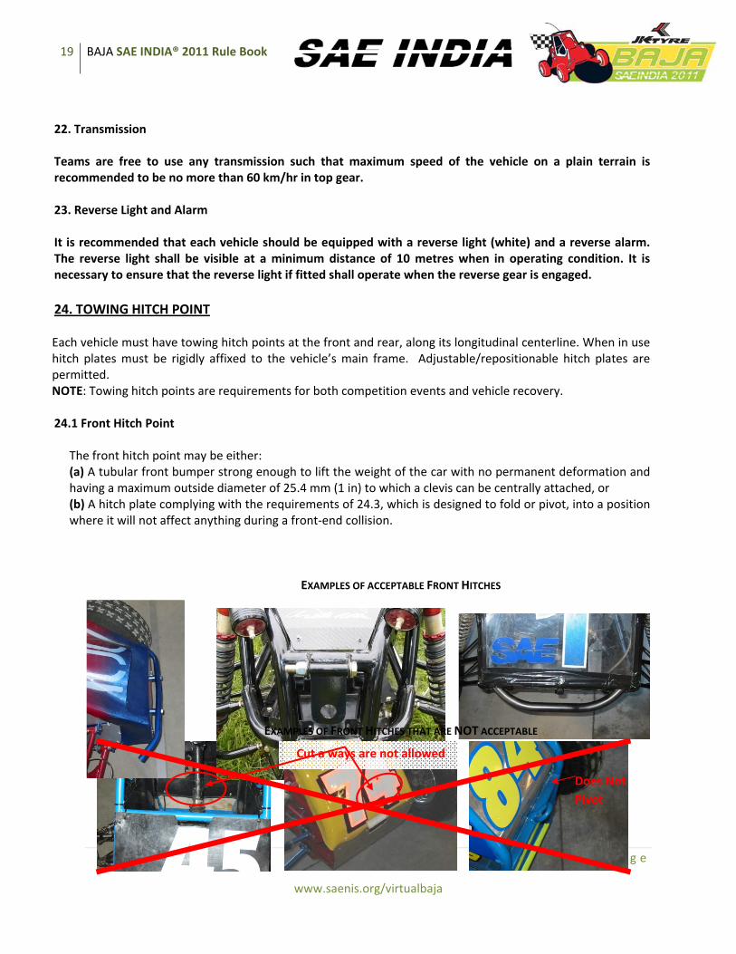
22. Transmission Teams are free to use any transmission such that maximum speed of the vehicle on a plain terrain is recommended to be no more than 60 km/hr in top gear. 23. Reverse Light and Alarm It is recommended that each vehicle should be equipped with a reverse light (white) and a reverse alarm. The reverse light shall be visible at a minimum distance of 10 metres when in operating condition. It is necessary to ensure that the reverse light if fitted shall operate when the reverse gear is engaged. 24. TOWING HITCH POINT Each vehicle must have towing hitch points at the front and rear, along its longitudinal centerline. When in use hitch plates must be rigidly affixed to the vehicle’s main frame. Adjustable/repositionable hitch plates are permitted. NOTE: Towing hitch points are requirements for both competition events and vehicle recovery. 24.1 Front Hitch Point
The front hitch point may be either: (a) A tubular front bumper strong enough to lift the weight of the car with no permanent deformation and having a maximum outside diameter of 25.4 mm (1 in) to which a clevis can be centrally attached, or (b) A hitch plate complying with the requirements of 24.3, which is designed to fold or pivot, into a position where it will not affect anything during a front‐end collision.
EXAMPLES OF ACCEPTABLE FRONT HITCHES
EXAMPLES OF FRONT HITCHES THAT ARE NOT ACCEPTABLE
Cut a ways are not allowed
Does Not Pivot

20 BAJA SAE INDIA® 2011 Rule Book
www.bajasaeindia.org 20 | P a g e
www.saenis.org/virtualbaja
24.2 Rear Hitch Plate
The rear hitch point must be a plate complying with the requirements of 24.3.
24.3 Hitch Plate Requirements – Maximum and Minimum
Towing plate Maximum thickness ‐ 9.5 mm (0.375 in.) Hole diameter Minimum ‐ 25.4 mm (1.0 in.) Radial clearance Maximum from hole ‐ 25.4 mm (1.0in) Hole to tube Minimum clearance – 19.0 mm (.75 in)
25. Vehicle Identification 25.1 Number Assignment
Assigned numbers may be found on the Baja SAE India website in the “registered team list” after final registration. It is each team’s responsibility to provide its vehicle numbers. The numbers must be clearly visible from sides, both the front and rear of the vehicle. Additionally the team must see that the numbers remain readable throughout the competition. If a vehicle’s numbers are illegible then it may not be scored. COMMENT: Schools which are entering more than one vehicle should consider painting them in individually distinctive colors to facilitate in lap counting.
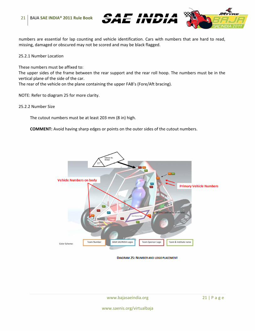
25.2 Vehicle Number – Primary Cutout Each vehicle must prominently display its number as either a silhouette or stencil form cutout. This must form a pyramid shaped plate situated at the top of the vehicle with the number sticker as stated in 25.3 & should be visible when viewed from all 4 sides of the vehicle. Painted‐on numbers or stencils/decals mounted flush to a body panel shall not be allowed. The numbers must allow mud to shed during dynamic events, so that cars can be identified accurately. The number must be a block style letter that is clear and easy to read as these
21 BAJA SAE INDIA® 2011 Rule Book
www.bajasaeindia.org 21 | P a g e
www.saenis.org/virtualbaja
numbers are essential for lap counting and vehicle identification. Cars with numbers that are hard to read, missing, damaged or obscured may not be scored and may be black flagged. 25.2.1 Number Location These numbers must be affixed to: The upper sides of the frame between the rear support and the rear roll hoop. The numbers must be in the vertical plane of the side of the car. The rear of the vehicle on the plane containing the upper FAB’s (Fore/Aft bracing). NOTE: Refer to diagram 25 for more clarity. 25.2.2 Number Size
The cutout numbers must be at least 203 mm (8 in) high. COMMENT: Avoid having sharp edges or points on the outer sides of the cutout numbers.

22 BAJA SAE INDIA® 2011 Rule Book
www.bajasaeindia.org 22 | P a g e
www.saenis.org/virtualbaja
25.3 Vehicle Number – Body
All vehicles must display their assigned number in block numerals on the front and both sides. These numbers must be at least 20.3 cm (8 inches) high, have a minimum line width of 2.54 cm (1 inch) and must strongly contrast with the background vehicle color.
25.4 College Name All vehicles must display their college name or initials, in roman characters, if unique and generally recognized, on each side in characters at least 2.5 cm (1 inch) high. Teams may also display their college name in non‐roman characters provided that the roman character set is highest on the car. 25.5 Sponsor Logos
25.5.1 Event Sponsor Logos Sponsor’s logos must be displayed in a prominent space on each side of the vehicle (as per the diagram 25). These will be distributed during registration at the event site.
25.5.2 SAE India Logo SAE India logos would be provided to the teams at the event site only. These are required to be pasted on both sides of the vehicle, at the centre of the side panels, and above the head of the driver, at the firewall (refer diagram 25). 25.5.3 Sponsor Identification Teams may display advertising from their vehicle’s sponsors, provided it is in good taste and does not conflict with the vehicle’s number. NOTE: Please refer to the paint and logo placement guidelines as annexed. 26. Transponders 26.1 Transponders
Transponders will be used as part of the primary timing system for all closed loop dynamic events. One transponder will be provided to each team free of cost at the time of the event (These will have to be returned at the end of the endurance run). However it is the responsibility of the teams to design a secure and safe mounting for the transponders.
23 BAJA SAE INDIA® 2011 Rule Book
www.bajasaeindia.org 23 | P a g e
www.saenis.org/virtualbaja
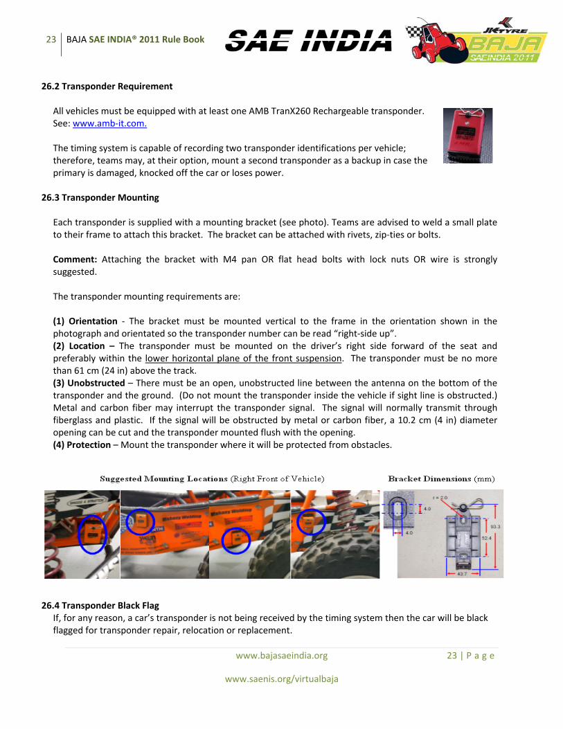
26.2 Transponder Requirement All vehicles must be equipped with at least one AMB TranX260 Rechargeable transponder. See: www.amb‐it.com. The timing system is capable of recording two transponder identifications per vehicle; therefore, teams may, at their option, mount a second transponder as a backup in case the primary is damaged, knocked off the car or loses power.
26.3 Transponder Mounting
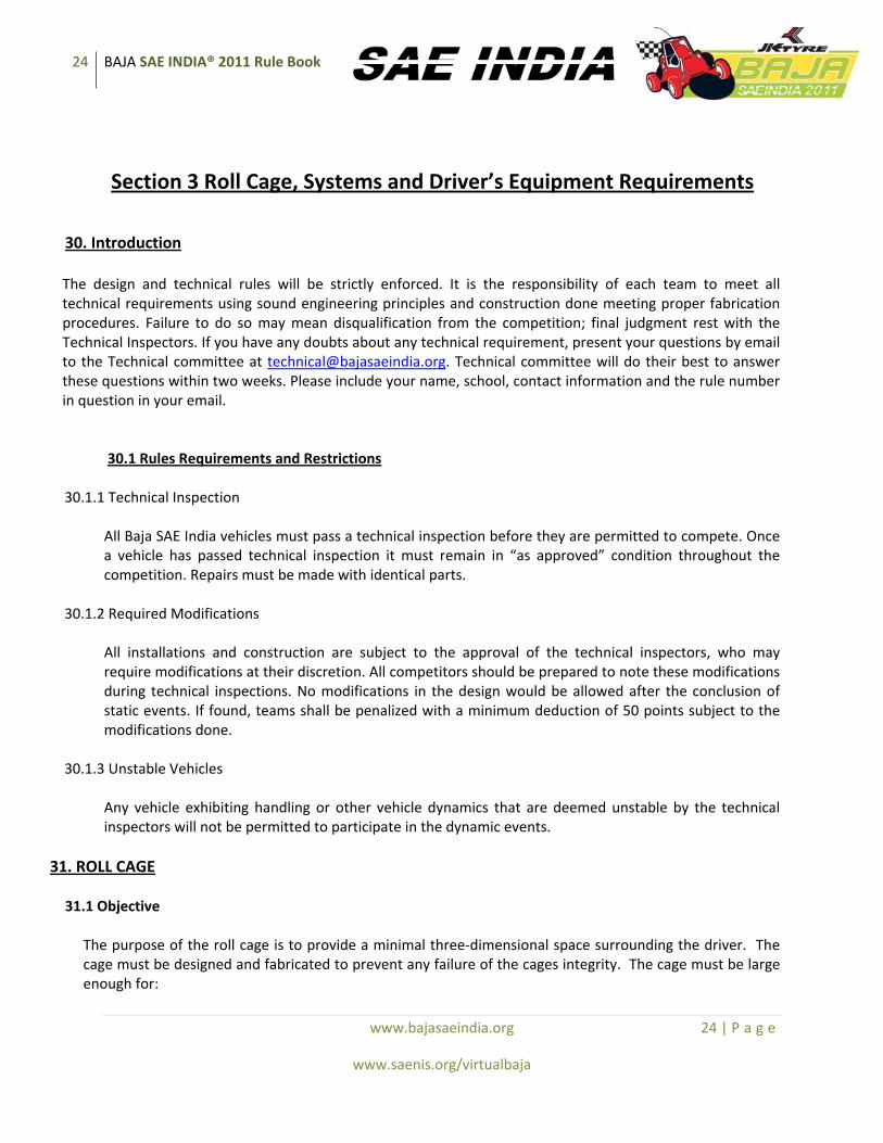
Each transponder is supplied with a mounting bracket (see photo). Teams are advised to weld a small plate to their frame to attach this bracket. The bracket can be attached with rivets, zip‐ties or bolts. Comment: Attaching the bracket with M4 pan OR flat head bolts with lock nuts OR wire is strongly suggested.
The transponder mounting requirements are: (1) Orientation ‐ The bracket must be mounted vertical to the frame in the orientation shown in the photograph and orientated so the transponder number can be read “right‐side up”. (2) Location – The transponder must be mounted on the driver’s right side forward of the seat and preferably within the lower horizontal plane of the front suspension. The transponder must be no more than 61 cm (24 in) above the track. (3) Unobstructed – There must be an open, unobstructed line between the antenna on the bottom of the transponder and the ground. (Do not mount the transponder inside the vehicle if sight line is obstructed.) Metal and carbon fiber may interrupt the transponder signal. The signal will normally transmit through fiberglass and plastic. If the signal will be obstructed by metal or carbon fiber, a 10.2 cm (4 in) diameter opening can be cut and the transponder mounted flush with the opening. (4) Protection – Mount the transponder where it will be protected from obstacles.
26.4 Transponder Black Flag
If, for any reason, a car’s transponder is not being received by the timing system then the car will be black flagged for transponder repair, relocation or replacement.
24 BAJA SAE INDIA® 2011 Rule Book
www.bajasaeindia.org 24 | P a g e
www.saenis.org/virtualbaja
Section 3 Roll Cage, Systems and Driver’s Equipment Requirements
30. Introduction The design and technical rules will be strictly enforced. It is the responsibility of each team to meet all technical requirements using sound engineering principles and construction done meeting proper fabrication procedures. Failure to do so may mean disqualification from the competition; final judgment rest with the Technical Inspectors. If you have any doubts about any technical requirement, present your questions by email to the Technical committee at [email protected]. Technical committee will do their best to answer these questions within two weeks. Please include your name, school, contact information and the rule number in question in your email.
30.1 Rules Requirements and Restrictions 30.1.1 Technical Inspection
All Baja SAE India vehicles must pass a technical inspection before they are permitted to compete. Once a vehicle has passed technical inspection it must remain in “as approved” condition throughout the competition. Repairs must be made with identical parts.
30.1.2 Required Modifications
All installations and construction are subject to the approval of the technical inspectors, who may require modifications at their discretion. All competitors should be prepared to note these modifications during technical inspections. No modifications in the design would be allowed after the conclusion of static events. If found, teams shall be penalized with a minimum deduction of 50 points subject to the modifications done.
30.1.3 Unstable Vehicles
Any vehicle exhibiting handling or other vehicle dynamics that are deemed unstable by the technical inspectors will not be permitted to participate in the dynamic events.
31. ROLL CAGE 31.1 Objective
The purpose of the roll cage is to provide a minimal three‐dimensional space surrounding the driver. The cage must be designed and fabricated to prevent any failure of the cages integrity. The cage must be large enough for:
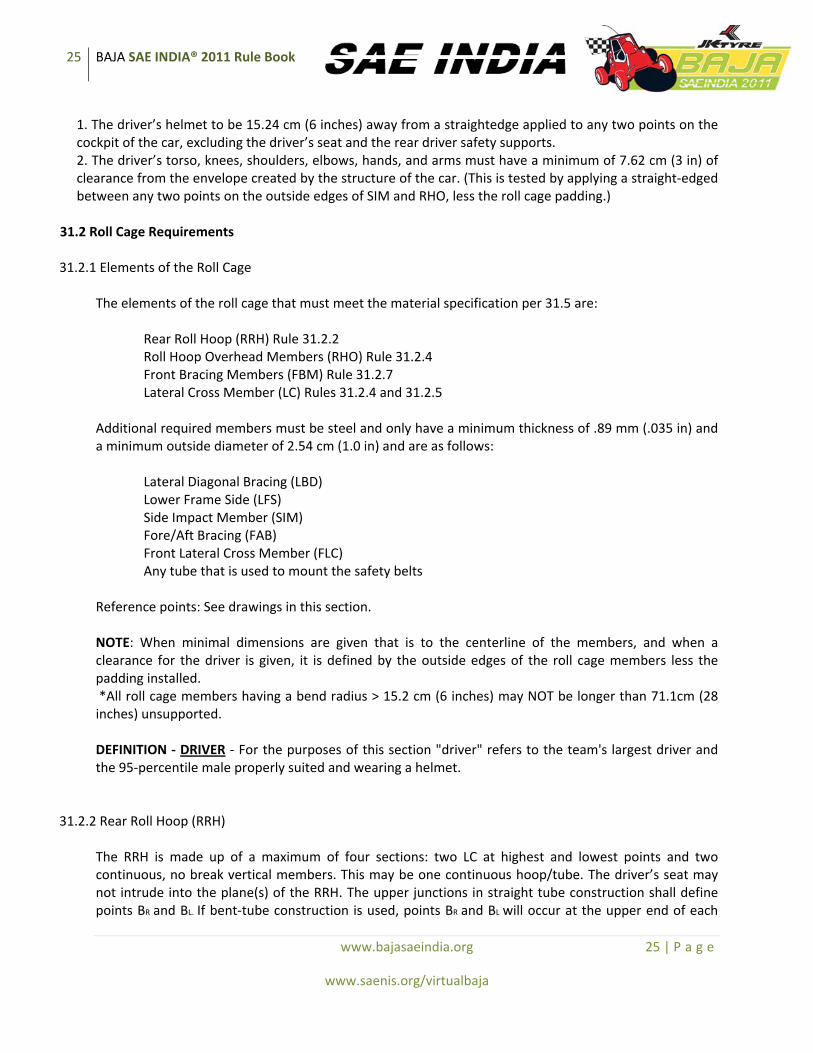
25 BAJA SAE INDIA® 2011 Rule Book
www.bajasaeindia.org 25 | P a g e
www.saenis.org/virtualbaja
1. The driver’s helmet to be 15.24 cm (6 inches) away from a straightedge applied to any two points on the cockpit of the car, excluding the driver’s seat and the rear driver safety supports. 2. The driver’s torso, knees, shoulders, elbows, hands, and arms must have a minimum of 7.62 cm (3 in) of clearance from the envelope created by the structure of the car. (This is tested by applying a straight‐edged between any two points on the outside edges of SIM and RHO, less the roll cage padding.)
31.2 Roll Cage Requirements 31.2.1 Elements of the Roll Cage
The elements of the roll cage that must meet the material specification per 31.5 are:
Rear Roll Hoop (RRH) Rule 31.2.2 Roll Hoop Overhead Members (RHO) Rule 31.2.4 Front Bracing Members (FBM) Rule 31.2.7 Lateral Cross Member (LC) Rules 31.2.4 and 31.2.5
Additional required members must be steel and only have a minimum thickness of .89 mm (.035 in) and a minimum outside diameter of 2.54 cm (1.0 in) and are as follows:
Lateral Diagonal Bracing (LBD) Lower Frame Side (LFS) Side Impact Member (SIM) Fore/Aft Bracing (FAB) Front Lateral Cross Member (FLC) Any tube that is used to mount the safety belts
Reference points: See drawings in this section.
NOTE: When minimal dimensions are given that is to the centerline of the members, and when a clearance for the driver is given, it is defined by the outside edges of the roll cage members less the padding installed. *All roll cage members having a bend radius > 15.2 cm (6 inches) may NOT be longer than 71.1cm (28 inches) unsupported. DEFINITION ‐ DRIVER ‐ For the purposes of this section "driver" refers to the team's largest driver and the 95‐percentile male properly suited and wearing a helmet.
31.2.2 Rear Roll Hoop (RRH)
The RRH is made up of a maximum of four sections: two LC at highest and lowest points and two continuous, no break vertical members. This may be one continuous hoop/tube. The driver’s seat may not intrude into the plane(s) of the RRH. The upper junctions in straight tube construction shall define points BR and BL. If bent‐tube construction is used, points BR and BL will occur at the upper end of each

26 BAJA SAE INDIA® 2011 Rule Book
www.bajasaeindia.org 26 | P a g e
www.saenis.org/virtualbaja
bend (See RC1). The RRH shall extend upward vertically +/‐ 20 degrees from points A to points B. The RRH must also be a minimum of 73.6 cm (29 in) wide at 68.6 cm (27 in) above the driver’s seat (checked by a template).
RC 1 31.2.3 Rear Roll Hoop Lateral Diagonal Bracing (LDB) Lateral bracing for the Rear Roll Hoop shall begin at a point along the vertical portion of the RRH within 12.7 cm (5 inches) vertically of point BL or BR and extend diagonally to a point no farther than 12.7 cm (5 inches) above point AR or AL respectively. (See RC2) The vertical angle between the RRH and the LDB must be no less than 20 degrees. Lateral bracing may consist of two or more members.
RC2 31.2.4 Roll Hoop Overhead members (RHO)
Roll Hoop Overhead members shall join the RRH within 5.1 cm (2 inches) vertically or laterally of points B and extend generally horizontal to point C. The tubes must be continuous and no break members from point B to point C are allowed. The RHO shall be located above the driver’s seat by a minimum of 104.1 cm (41 inches). Points C should be located forward of the driver’s seat by a minimum of 30.5 cm (12
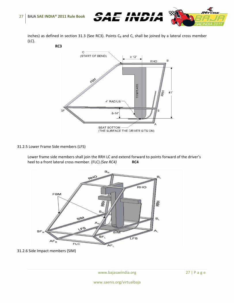
27 BAJA SAE INDIA® 2011 Rule Book
www.bajasaeindia.org 27 | P a g e
www.saenis.org/virtualbaja
inches) as defined in section 31.3 (See RC3). Points CR and CL shall be joined by a lateral cross member (LC).
RC3
31.2.5 Lower Frame Side members (LFS)
Lower frame side members shall join the RRH LC and extend forward to points forward of the driver’s heel to a front lateral cross member. (FLC) (See RC4) RC4
31.2.6 Side Impact members (SIM)

28 BAJA SAE INDIA® 2011 Rule Book
www.bajasaeindia.org 28 | P a g e
www.saenis.org/virtualbaja
Side impact members shall join the RRH at points S and extend horizontally to points SF forward of the driver’s toes. (See RC4) The SIM shall be between 20.3 cm (8 inches) and 35.6 cm (14 inches) (as measured vertically) above the area of the seat in contact with the driver (See RC3). NOTE: The driver’s feet must be behind the plane created by points AFR,L and SFR,L. If the tube between SFR, L is below the driver’s toes then an additional bar will be required above the driver’s toes. (The intent of this is to protect the driver’s feet from a tire intrusion.)
31.2.7 Front Bracing members (FBM)
Front bracing members shall join the RHO, the SIM and the LFS (See RC5). The upper front bracing members (FBMUP) should extend downward and forward and join point C on the RHO to the SIM at or behind points SF. The FBM members must be continuous and no break members from point C to the SIM are allowed. The angle between the FBMUP and the vertical should be less than 45 degrees.
RC5
31.2.8 Roll Hoop Bracing (FAB)
The roll hoop can be braced in the front and/or rear. The hoop must be braced on both right and left sides. From a side view, the bracing must be triangulated, with the maximum length of any member not to exceed 101.6 cm (40 inches) between attachment points. The angles of the triangulation must be no less than 20 degrees. A bent tube cannot exceed 81.3 cm (32 inches) between attachment points.

29 BAJA SAE INDIA® 2011 Rule Book
www.bajasaeindia.org 29 | P a g e
www.saenis.org/virtualbaja
31.2.8.1 Front Bracing If front bracing is used it must connect FBMup, LFS and the SIM. Front bracing must be attached as close as possible to the top of the roll cage (point C).
31.2.8.2 Rear Bracing
If rear bracing is used it must be attached as close as possible to the top of the roll hoop along the outer perimeter. The bracing must be triangulated and connect back to the RRH below the SIM.
31.2.9 RHO/FBM Gusseting If the RHO and FBM are not fabricated from a continuous tube, a gusset is required at point C. Gussets shall be made of steel plate, be triangular from a side view, and have a minimum thickness of 0.065”. The gussets shall be welded to the sides of the tubes and not directly in the plane of the tubes making up each joint (See RC6). The length of the gusset must be at least 3 times the tube diameter.
RC 6 The example on the left shows a design where gusseting is required at point C; the example on the right shows a frame where gusseting would not be required at point C. 31.2.10 Butt Joints All butt joints within any of the elements on the roll cage listed in section 31.2.1 (excluding the required no break members described in 31.2.2, 31.2.4 and 31.2.7) must be reinforced with a welded sleeve. A butt joint is defined as a joint where two tubes come together generally along the same line and are not supported by a third tube at the node. The sleeve must be designed to tightly fit on the inside on the joint being reinforced (i.e. external sleeves are not allowed), must extend into each side of the sleeved joint, a length of at least two times the diameter of the tubes being reinforced, and be made from steel

30 BAJA SAE INDIA® 2011 Rule Book
www.bajasaeindia.org 30 | P a g e
www.saenis.org/virtualbaja
at least as thick as the tubes being reinforced. In addition to meeting basic geometry requirements, the sleeve must be designed and fabricated to both reinforce the joint and to distribute the stress concentrations of the heat affected zone. 31.2.11 Weld Confirmation Checks Teams must conduct weld confirmation testing for each welder that welds their vehicle roll cage. The team must demonstrate its ability to produce welded joints of a known quality with materials, tools and procedures similar to those being used in the fabrication of the chassis The team must conduct destructive testing using the following requirements: The following definitions will apply to the entirety of rule 31.2.11:
‐ As‐Built Vehicle: the vehicle presented at technical inspection ‐ Roll Cage Elements: elements of the roll cage as discussed in rule 31.2.1 ‐ Roll Cage Welds: any weld joining two or more roll cage elements or one or more roll cage elements and one or more gussets as discussed in rule 31.2.9 ‐ Roll Cage Material: tubing of the same geometry and alloy as the roll cage elements of the as‐built vehicle ‐ Roll Cage Welder: any person that performs welding of the roll cage welds of the as‐built
vehicle
Each roll cage welder must demonstrate sufficient welding skill and craftsmanship with the tools, processes and roll cage material. In addition to visual inspection of the as‐built vehicle, the national technical inspectors will collect and inspect welding samples during the technical inspection process to determine dynamic and endurance event competition eligibility. Teams unable to submit welding samples of adequate quality, as defined below, shall not be eligible to compete in any dynamic or endurance event. NOTE: Only students are to perform welding on the as‐built vehicle, and roll cage welders may be asked to demonstrate their welding skills during technical inspection. Each team must submit two (2) samples for each roll cage welder, both of which are constructed of roll cage material which have been welded with the same tools and processes as those of the as‐built vehicle and which have also been subject to the following destructive testing and inspection:
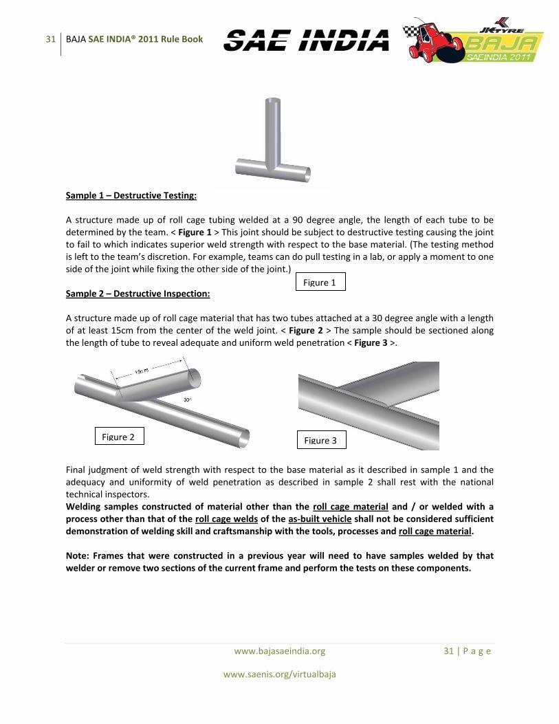
31 BAJA SAE INDIA® 2011 Rule Book
www.bajasaeindia.org 31 | P a g e
www.saenis.org/virtualbaja
Sample 1 – Destructive Testing: A structure made up of roll cage tubing welded at a 90 degree angle, the length of each tube to be determined by the team. < Figure 1 > This joint should be subject to destructive testing causing the joint to fail to which indicates superior weld strength with respect to the base material. (The testing method is left to the team’s discretion. For example, teams can do pull testing in a lab, or apply a moment to one side of the joint while fixing the other side of the joint.) Sample 2 – Destructive Inspection: A structure made up of roll cage material that has two tubes attached at a 30 degree angle with a length of at least 15cm from the center of the weld joint. < Figure 2 > The sample should be sectioned along the length of tube to reveal adequate and uniform weld penetration < Figure 3 >.
Final judgment of weld strength with respect to the base material as it described in sample 1 and the adequacy and uniformity of weld penetration as described in sample 2 shall rest with the national technical inspectors. Welding samples constructed of material other than the roll cage material and / or welded with a process other than that of the roll cage welds of the as‐built vehicle shall not be considered sufficient demonstration of welding skill and craftsmanship with the tools, processes and roll cage material. Note: Frames that were constructed in a previous year will need to have samples welded by that welder or remove two sections of the current frame and perform the tests on these components.
Figure 1
Figure 2 Figure 3

32 BAJA SAE INDIA® 2011 Rule Book
www.bajasaeindia.org 32 | P a g e
www.saenis.org/virtualbaja
31.2.12 Final Judgment
The rules are considered a minimum but the final judgment will rest with the Technical Inspectors. If during the event, any frame shows signs of yield and/or failure the car will be removed from competition until the technical inspectors confirm that the frame complies with the rules again. COMMENT: Note that in all cases, especially bent‐tube construction, technical inspectors may require additional bracing if they feel the roll cage does not offer adequate protection. Any tubes showing cracks and deformation do not comply with the rules. It shall be compulsory that the teams comply with this requirement as and when instructed by the Technical Inspectors.
31.3 Head Restraint
A head restraint must be provided on the car to limit rearward motion of the head in case of an accident. The restraint must have a minimum area of 232 sq. cm (36 sq inches), and be padded with a closed cell foam that has a density of 50‐100 kg/m^3. The restraint must be a minimum thickness of 3.8 cm (1.5 inches), and be located no more than 2.5 cm (1 inch) away from the helmet in the uncompressed state. The head restraint must be securely mounted to the vehicle. The head restraint must meet the above requirements for all drivers. NOTE: If the head restraint is already a part of the seat, then no need to include a separate one.
31.4 Driver Head Clearance
For driver head clearance, the roll cage must extend a minimum of 104.1 cm (41 inches) above the seating surface to the bottom of the upper roll cage tubes measured vertically using the template in RC 3. The template radiused bottom should be placed in the joint of the seat base and the seat backrest and positioned vertically. The template “tee” top describes the projection of the required clearance height forward and rearward. While the template fixes the clearance height forward, the clearance height rearward must be extended in each design over the helmet top of a seated and secured driver. Taller drivers may be accommodated by lengthening the template vertical member and raising the entire clearance height envelope above the 104.1 cm (41 inches) minimum.
31.4.1 Head Clearance – Minimum
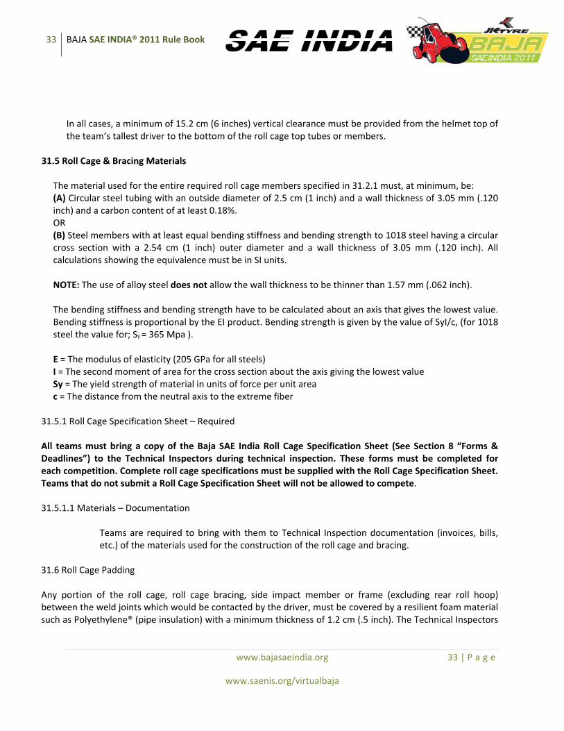
33 BAJA SAE INDIA® 2011 Rule Book
www.bajasaeindia.org 33 | P a g e
www.saenis.org/virtualbaja
In all cases, a minimum of 15.2 cm (6 inches) vertical clearance must be provided from the helmet top of the team’s tallest driver to the bottom of the roll cage top tubes or members.
31.5 Roll Cage & Bracing Materials
The material used for the entire required roll cage members specified in 31.2.1 must, at minimum, be: (A) Circular steel tubing with an outside diameter of 2.5 cm (1 inch) and a wall thickness of 3.05 mm (.120 inch) and a carbon content of at least 0.18%. OR (B) Steel members with at least equal bending stiffness and bending strength to 1018 steel having a circular cross section with a 2.54 cm (1 inch) outer diameter and a wall thickness of 3.05 mm (.120 inch). All calculations showing the equivalence must be in SI units. NOTE: The use of alloy steel does not allow the wall thickness to be thinner than 1.57 mm (.062 inch). The bending stiffness and bending strength have to be calculated about an axis that gives the lowest value. Bending stiffness is proportional by the EI product. Bending strength is given by the value of SyI/c, (for 1018 steel the value for; Sy = 365 Mpa ). E = The modulus of elasticity (205 GPa for all steels) I = The second moment of area for the cross section about the axis giving the lowest value Sy = The yield strength of material in units of force per unit area c = The distance from the neutral axis to the extreme fiber
31.5.1 Roll Cage Specification Sheet – Required All teams must bring a copy of the Baja SAE India Roll Cage Specification Sheet (See Section 8 “Forms & Deadlines”) to the Technical Inspectors during technical inspection. These forms must be completed for each competition. Complete roll cage specifications must be supplied with the Roll Cage Specification Sheet. Teams that do not submit a Roll Cage Specification Sheet will not be allowed to compete. 31.5.1.1 Materials – Documentation
Teams are required to bring with them to Technical Inspection documentation (invoices, bills, etc.) of the materials used for the construction of the roll cage and bracing.
31.6 Roll Cage Padding Any portion of the roll cage, roll cage bracing, side impact member or frame (excluding rear roll hoop) between the weld joints which would be contacted by the driver, must be covered by a resilient foam material such as Polyethylene® (pipe insulation) with a minimum thickness of 1.2 cm (.5 inch). The Technical Inspectors

34 BAJA SAE INDIA® 2011 Rule Book
www.bajasaeindia.org 34 | P a g e
www.saenis.org/virtualbaja
shall measure this dimension as per the Technical Inspection Sheet. Any vehicle not meeting this requirement shall not be allowed to take part in all events. 31.7 Sharp Edges on Roll Cage – Prohibited All sharp edges which might endanger the driver, crew, officials and safety staff must be eliminated by shielding and/or padding. This includes brackets, gussets, sheet stock, fastener ends, clamps, zip ties or other features accessible during servicing, judging or competition impact or roll over. The decision of the Technical Inspectors in this regard is final and shall be binding on all teams to comply. 31.8 Bolted Roll Cages
Bolted Roll cages are acceptable only if the following requirements are met: (A) Flanges or tabs must be twice (2X) the thickness of the tube structures, made of the same material type. They must be properly welded to each tubing part to be joined. (B) Flange mounts must be twice (2X) the diameter of the attached tubing, flush mated, and with no gap between the faces greater than .07 mm (.003) inches. (C) Tab mounts must be dual, parallel and on each side of the tubing to which they are welded, having a welded length of at least twice (2X) the diameter of the adjoined. Tubing held by bolts must be reinforced such that the area through which the bolt passes cannot be compressed from tightening or impact. 31.9 Driver Seat The use of a driver seat is mandatory; cushioning or padding attached to the frame and/or firewall will not be accepted as a seat. The seat shall be fastened to the frame and shall support the entire body of the driver (full torso and head). The load shall not be transferred to the firewall or any other member except those supporting the seat. A clearance of 3” between the firewall, Side Impact Members and the seat must be maintained. The use of commercially available rally seats is highly recommended.
32. COCKPIT 32.1 Design Objective
The cockpit must be designed to (1) protect the driver and (2) permit easy driver exit in an emergency.
32.2 Driver Exit Time
All drivers must be able to exit on either side of the vehicle within five (5) seconds. Exit time begins with the driver in the fully seated position, hands in driving position on the connected steering wheel, and wearing the required driver equipment. Exit time will stop when the driver has both feet on the ground. Driver’s exit time must be demonstrated by a team driver, or drivers selected by the technical inspectors.
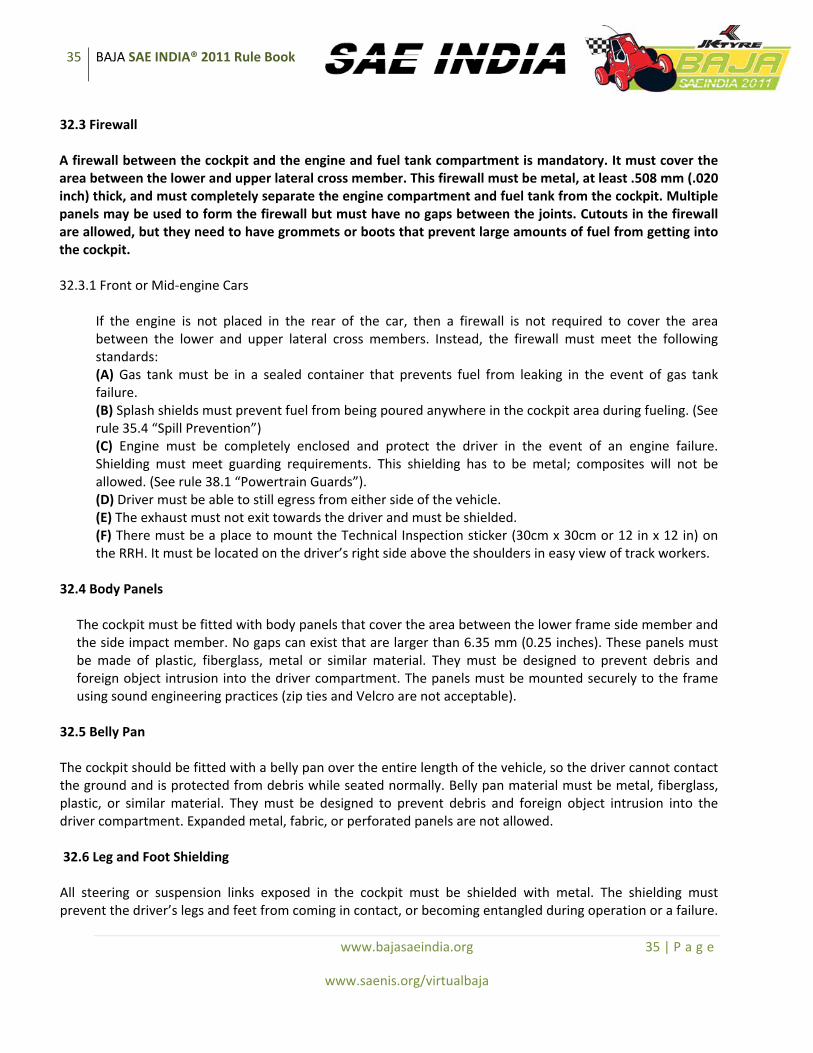
35 BAJA SAE INDIA® 2011 Rule Book
www.bajasaeindia.org 35 | P a g e
www.saenis.org/virtualbaja
32.3 Firewall A firewall between the cockpit and the engine and fuel tank compartment is mandatory. It must cover the area between the lower and upper lateral cross member. This firewall must be metal, at least .508 mm (.020 inch) thick, and must completely separate the engine compartment and fuel tank from the cockpit. Multiple panels may be used to form the firewall but must have no gaps between the joints. Cutouts in the firewall are allowed, but they need to have grommets or boots that prevent large amounts of fuel from getting into the cockpit. 32.3.1 Front or Mid‐engine Cars
If the engine is not placed in the rear of the car, then a firewall is not required to cover the area between the lower and upper lateral cross members. Instead, the firewall must meet the following standards: (A) Gas tank must be in a sealed container that prevents fuel from leaking in the event of gas tank failure. (B) Splash shields must prevent fuel from being poured anywhere in the cockpit area during fueling. (See rule 35.4 “Spill Prevention”) (C) Engine must be completely enclosed and protect the driver in the event of an engine failure. Shielding must meet guarding requirements. This shielding has to be metal; composites will not be allowed. (See rule 38.1 “Powertrain Guards”). (D) Driver must be able to still egress from either side of the vehicle. (E) The exhaust must not exit towards the driver and must be shielded. (F) There must be a place to mount the Technical Inspection sticker (30cm x 30cm or 12 in x 12 in) on the RRH. It must be located on the driver’s right side above the shoulders in easy view of track workers.
32.4 Body Panels
The cockpit must be fitted with body panels that cover the area between the lower frame side member and the side impact member. No gaps can exist that are larger than 6.35 mm (0.25 inches). These panels must be made of plastic, fiberglass, metal or similar material. They must be designed to prevent debris and foreign object intrusion into the driver compartment. The panels must be mounted securely to the frame using sound engineering practices (zip ties and Velcro are not acceptable).
32.5 Belly Pan The cockpit should be fitted with a belly pan over the entire length of the vehicle, so the driver cannot contact the ground and is protected from debris while seated normally. Belly pan material must be metal, fiberglass, plastic, or similar material. They must be designed to prevent debris and foreign object intrusion into the driver compartment. Expanded metal, fabric, or perforated panels are not allowed. 32.6 Leg and Foot Shielding All steering or suspension links exposed in the cockpit must be shielded with metal. The shielding must prevent the driver’s legs and feet from coming in contact, or becoming entangled during operation or a failure.
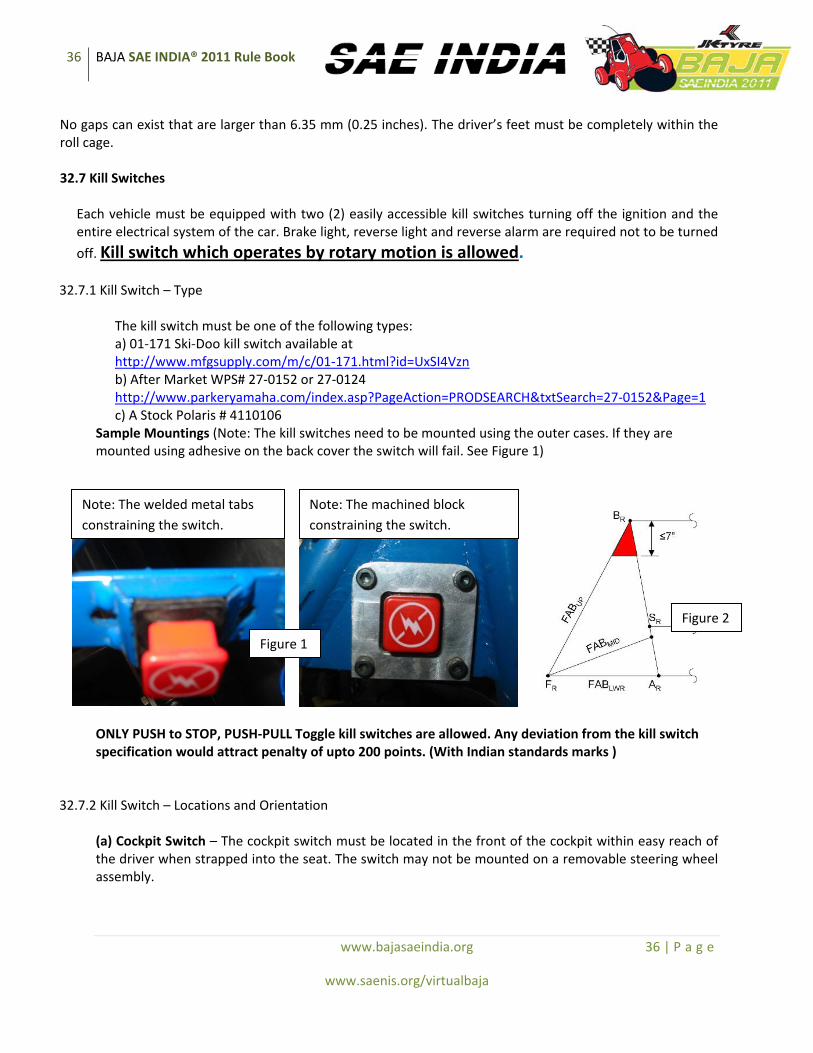
36 BAJA SAE INDIA® 2011 Rule Book
www.bajasaeindia.org 36 | P a g e
www.saenis.org/virtualbaja
No gaps can exist that are larger than 6.35 mm (0.25 inches). The driver’s feet must be completely within the roll cage. 32.7 Kill Switches
Each vehicle must be equipped with two (2) easily accessible kill switches turning off the ignition and the entire electrical system of the car. Brake light, reverse light and reverse alarm are required not to be turned
off. Kill switch which operates by rotary motion is allowed. 32.7.1 Kill Switch – Type
The kill switch must be one of the following types: a) 01‐171 Ski‐Doo kill switch available at http://www.mfgsupply.com/m/c/01‐171.html?id=UxSI4Vzn b) After Market WPS# 27‐0152 or 27‐0124 http://www.parkeryamaha.com/index.asp?PageAction=PRODSEARCH&txtSearch=27‐0152&Page=1 c) A Stock Polaris # 4110106
Sample Mountings (Note: The kill switches need to be mounted using the outer cases. If they are mounted using adhesive on the back cover the switch will fail. See Figure 1)
ONLY PUSH to STOP, PUSH‐PULL Toggle kill switches are allowed. Any deviation from the kill switch specification would attract penalty of upto 200 points. (With Indian standards marks )
32.7.2 Kill Switch – Locations and Orientation
(a) Cockpit Switch – The cockpit switch must be located in the front of the cockpit within easy reach of the driver when strapped into the seat. The switch may not be mounted on a removable steering wheel assembly.
Note: The welded metal tabs constraining the switch.
Note: The machined block constraining the switch.
Figure 1
Figure 2

37 BAJA SAE INDIA® 2011 Rule Book
www.bajasaeindia.org 37 | P a g e
www.saenis.org/virtualbaja
(b) External Switch – The external switch must be mounted on the driver’s right side of the vehicle, on a panel perpendicular to the firewall between RRH and Rear Bracing within the red area, and behind the plane of the main roll hoop (see Figure 2). The switch cannot be more than 177.8 mm (7 inches) vertically below point Br. The switch must be within easy reach of track workers. The switch must be mounted rigidly, with no sharp edges in that area. (C) Note : The final authority of suitability of any kill switch is left to the discretion of the Technical inspectors.
32.7.3 Kill Switch – Wiring
All wiring to kill switches must be sealed, protected or securely attached to the frame to prevent the wires from being entangled with the driver or obstacles. Sound engineering practices must be used.
32.8 Fire Extinguisher – Size and Location
Each vehicle must have two identical fire extinguishers with an ISI rating. Each must have a minimum capacity of 1 litre. One must be mounted in the cockpit below the driver’s head, with the top half above the side impact member on the right side of the firewall and be easily accessible by course workers. The manufacturer mounts must be used; they must be metal and have a metal draw latch. This mount must be securely fastened to the vehicle frame (RRH) and it must resist shaking loose over rough terrain, while allowing the course workers to remove it easily if necessary. The second must be brought to technical inspection with mounting accessories; it will be used as a replacement if needed. All fire extinguishers must be equipped with a 2009 manufacturer installed dial pressure gauge. The gauge must be readable by the Technical Inspectors. Fire extinguishers must be labeled with school name and vehicle number.
32.9 Throttle
Only foot operated throttle controls are allowed. Cars having hand operated throttle will not be allowed to start any event. A wide‐open throttle stop must be mounted at the pedal. Mechanical, hydraulic or other throttle controls must be designed to return to idle‐stop in the event of a failure. Foot pedals must be positioned so as to avoid foot entrapment in any position.
32.9.1 Throttle Extensions
Teams may not add any type of extension to either the control surfaces or to the driver in order to operate the vehicle. For example, drivers may not add blocks of wood to their feet so that they can reach the controls of the vehicle.
33. DRIVER RESTRAINT 33.1 Minimum Four Strap System Required
All drivers must use a minimum of a four (4) strap restraint harness. However, it is strongly recommended to use a 5 point restraint harness meeting the following specifications. A five‐point system consists of a 76

38 BAJA SAE INDIA® 2011 Rule Book
www.bajasaeindia.org 38 | P a g e
www.saenis.org/virtualbaja
mm (3 inch) wide lap belt and approximately 76 mm (3 inch) wide shoulder harness straps, along with a fifth, anti‐submarine belt (vertical strap that goes between the legs), preventing the lap belt from rising along the driver’s waist. The restraint system installation is subject to approval of the Technical Inspector. The restraint system must be worn tightly. No more than a finger width gap between the belts and the driver will be allowed when the belt is pulled.
33.1.1 Release Mechanism
All belts must join with a single metal‐to‐metal quick release lever type buckle. No camlock systems are allowed.
33.1.2 Safety Harness Expiration The material of all straps must be Nylon or Dacron polyester and in new or perfect condition. All driver restraint systems must meet either SFI Specification 16.5/16.1, or FIA specification 8853/98 or ISI marks . The belts must bear the appropriate dated labels, and on Jan 1st of the competition year be no more than three years old.
33.2 Shoulder Harness The shoulder harness must be the over‐the‐shoulder type. Only separate shoulder straps are permitted (i.e. “Y”‐type shoulder straps are not allowed).
33.2.1 Vertical Location
The shoulder belts must NOT be mounted above the shoulder level, and must be protected by the firewall. Shoulder belts must be no more than 102 mm (4 inches) below the perpendicular from the spine to the seat back at the shoulder level.
33.2.2 Horizontal Location The shoulder harness mounting points must be between 178 mm (7 inches) and 229 mm (9 inches) apart (see Figure below ). The straps shall not pass through anything that will cause the center distance to be less than 178 mm (7 inches) from center to center of the strap. The straps shall not pass over anything that causes them to be more than 229 mm (9 inches) apart center to center.
33.2.3 Harness Attachment Points
The shoulder harness must be securely mounted to the primary structure. Shoulder belts must be looped around a frame tube and have something designed to limit the belt movement. The belts may go through the firewall as long as additional firewall material is added to protect that portion of the belt.

39 BAJA SAE INDIA® 2011 Rule Book
www.bajasaeindia.org 39 | P a g e
www.saenis.org/virtualbaja
33.2.4 Redirection of Harness Webbing
The redirection of harness webbing to facilitate stronger and simpler mounting designs shall not be made by any means. Specifically, webbing that is routed such that when tightened will bear a load onto the seat will not be accepted. All harness loads must pass directly onto the frame of the vehicle. (See Figure 4)
33.3 Lap & Anti‐Submarine Belts
The lap belt must pass around the pelvic area below the Anterior Superior Iliac Spines (the hip bones) (Figure 5). Under no condition may the lap belt be worn over the area of the intestines or abdomen. The lap belts should come through the seat at the bottom of the sides of the seat to maximize the wrap of the pelvic surface and continue in a straight line to the anchorage point. In side view, the lap belt must be at an angle of between 45 degrees and 65 degrees to the horizontal. This means that the centerline of the lap belt at the seat bottom should be approximately 76 mm (3 inches) forward of the seat back to seat bottom junction (see Figure 5). To fit drivers of differing statures correctly, in side view, the lap / anti‐submarine belts must be capable of pivoting freely by using either a shouldered bolt or an eye bolt attachment. Mounting lap belts by wrapping them around frame tubes is no longer acceptable. The lap belts should not be routed over the sides of the seat.
Figure 5 Figure 6 33.3.1 Specified Lap & Anti‐Submarine Belts Mounting
The frame tabs which accept the lap belt mounting tabs must meet the following requirements: 1) The lap belt tabs must be mounted in double‐shear. (See Figure 6) 2) The frame tabs that accept the lap belt tabs shall be no less than 2.3mm thick (.090”).
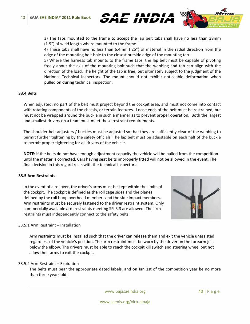
40 BAJA SAE INDIA® 2011 Rule Book
www.bajasaeindia.org 40 | P a g e
www.saenis.org/virtualbaja
3) The tabs mounted to the frame to accept the lap belt tabs shall have no less than 38mm (1.5”) of weld length where mounted to the frame. 4) These tabs shall have no less than 6.4mm (.25”) of material in the radial direction from the edge of the mounting bolt hole to the closest outside edge of the mounting tab. 5) Where the harness tab mounts to the frame tabs, the lap belt must be capable of pivoting freely about the axis of the mounting bolt such that the webbing and tab can align with the direction of the load. The height of the tab is free, but ultimately subject to the judgment of the National Technical Inspectors. The mount should not exhibit noticeable deformation when pulled on during technical inspection.
33.4 Belts
When adjusted, no part of the belt must project beyond the cockpit area, and must not come into contact with rotating components of the chassis, or terrain features. Loose ends of the belt must be restrained, but must not be wrapped around the buckle in such a manner as to prevent proper operation. Both the largest and smallest drivers on a team must meet these restraint requirements. The shoulder belt adjusters / buckles must be adjusted so that they are sufficiently clear of the webbing to permit further tightening by the safety officials. The lap belt must be adjustable on each half of the buckle to permit proper tightening for all drivers of the vehicle. NOTE: If the belts do not have enough adjustment capacity the vehicle will be pulled from the competition until the matter is corrected. Cars having seat belts improperly fitted will not be allowed in the event. The final decision in this regard rests with the technical inspectors.
33.5 Arm Restraints
In the event of a rollover, the driver’s arms must be kept within the limits of the cockpit. The cockpit is defined as the roll cage sides and the planes defined by the roll hoop overhead members and the side impact members. Arm restraints must be securely fastened to the driver restraint system. Only commercially available arm restraints meeting SFI 3.3 are allowed. The arm restraints must independently connect to the safety belts.
33.5.1 Arm Restraint – Installation
Arm restraints must be installed such that the driver can release them and exit the vehicle unassisted regardless of the vehicle’s position. The arm restraint must be worn by the driver on the forearm just below the elbow. The drivers must be able to reach the cockpit kill switch and steering wheel but not allow their arms to exit the cockpit.
33.5.2 Arm Restraint – Expiration
The belts must bear the appropriate dated labels, and on Jan 1st of the competition year be no more than three years old.

41 BAJA SAE INDIA® 2011 Rule Book
www.bajasaeindia.org 41 | P a g e
www.saenis.org/virtualbaja
33.5.3 Installations – General
All installations must prevent accidental unfastening from a direct pull, rollover or slide along the side.
34. BRAKING SYSTEM 34.1 Foot Brake
The vehicle must have at least two (2) independent hydraulic braking systems that act on all wheels and is operated by a single foot. The pedal must directly actuate the master cylinder (no cables are allowed). The brake system must be capable of locking ALL FOUR wheels in a static condition and dynamically on pavement AND an unpaved surface. Both the independent brake systems may be actuated by a tandem master cylinder.
34.2 Independent Brake Circuits
The vehicle must be have at least two (2) independent hydraulic systems such that in case of a leak or failure at any point in the system, effective braking power shall be maintained on at least two wheels. Each hydraulic system shall have its own fluid reserve either through separate reservoirs or by the use of a dammed, OEM‐style reservoir. Note: Plastic brake lines are not allowed.
34.3 Brake Light
The vehicle must be equipped with a red brake light that is mounted such that the light shines parallel to the ground, not up at an angle. The lens must be marked with an SAE “S” or “U” rating (i.e.: SAE IPRSTM) or if it is not rated as per SAE J759, it must be equal to or exceed these standards (Eg: OEM brake light assemblies)/. AIS and ISI rated brake lights are also permitted. The determination of whether or not a brake light meets the required standards rests with the Technical Inspectors.
34.4 Brake(s) Location
The brake(s) on the driven axle must operate through the final drive. Inboard braking through universal joints is permitted. Braking on a jackshaft or through an intermediate reduction stage is prohibited.
34.5 Cutting Brakes
Hand or feet operated “cutting brakes” are permitted provided section 34.1”Foot Brake” is also satisfied.

42 BAJA SAE INDIA® 2011 Rule Book
www.bajasaeindia.org 42 | P a g e
www.saenis.org/virtualbaja
35. FUEL SYSTEM & Fuel 35.1 System Location
The entire fuel system must be located within the roll cage envelope such that it is protected from impact. The tank mountings must be designed to resist shaking loose.
35.2 Fuel Tank Only a single fuel tank is permitted on the vehicle. Fuel tanks are restricted to a maximum capacity of 6 litres. Tanks used on portable genset may be used .No holes are allowed in the tank even if they have been repaired. The technical inspectors may hold back a vehicle from participation in dynamic events if they find the fuel tank or its mounting to be unsafe. The retail price must be included in the cost report. Quality, cleanliness of fuel tanks is important from both safety & engine working point of view Use of small inline fuel filter is a must after the tank to avoid fuel lines getting dirty / choked
35.3 Fuel Lines
All fuel lines must be located away from sharp edges, hot engine components and be protected from chafing. Grommetting is required where the lines pass through any member of the vehicle. Fuel lines are not allowed in the cockpit. All lines must be attached securely and be SAE rated fuel lines. Lines must be tight fitting & not come off due to jerks or vibrations. Fuel filters may be used.
35.4 Spill Prevention The fuel tank must be mounted so if fuel spills it will not come in contact with the driver or the engine. Complying with this rule will require a drip pan that is at least 203.2 mm (8 inches) in diameter or equivalent area and have sides of at least 38 mm (1.5 inches) high above the top edge of the tank.
Fuel spill prevention shall be checked by a 45 degree tilt test at the technical inspection site or any point of time during the event and any vehicle failing to comply shall not be allowed to start any dynamic event. 35.4.1 Spill Prevention Mounting
Mounting the drip pan and/or splash shield(s) directly to the fuel tank with a connection only around the fuel cap is insufficient and shall not be allowed. Drip pans must be mounted using sound engineering practices. Drip pans must be graded or inclined such that all spilled fuel drains from the drip pan – fuel must not pool anywhere in the pan.

43 BAJA SAE INDIA® 2011 Rule Book
www.bajasaeindia.org 43 | P a g e
www.saenis.org/virtualbaja
35.4.2 Spill Prevention Draining The fuel must drain from the drip pan through a drain line composed of pipe or tubing that carries the fuel to the bottom of the car and releases it under the car. (In competitions involving a water hazard, the fuel must not be deposited onto floatation material, but must instead be directed around or through the floatation by the drain line.) At no point in the drain system (the drain lines and any associated fittings) will the inner diameter be constricted to less than 9.53 mm (.375 inch) – this includes bolts with a hole drilled in the center used as a fitting. At least one drain line is required; multiple drain lines are allowed for the purpose of redundancy or to alleviate the pooling of fuel in different parts of the drip pan. Compliance shall be checked and any vehicle failing to comply shall not be allowed to start any dynamic event.
35.4.3 Spill Prevention Drain Material The drains must be either fuel line material, other pipe or tubing suitable for transferring fuel. Tubing, fittings, or sealing materials that are weakened or dissolved by fuel are unsafe for this application and will not be permitted. If tubing is used, it is highly recommended that a threaded and barbed fitting be used at the point where the drain line connects to the drip pan. Compliance shall be checked and any vehicle failing to comply shall not be allowed to start any dynamic event.
35.4.4 Filler Cap The standard filler caps provided with rated fuel tanks may not prevent fuel from leaking in the event of a rollover. Teams must ensure that the filler cap gasket does not breakdown in fuel, does not have any holes and prevents fuel from spilling. The cap must not come loose during dynamic events or allow fuel to spill out. Compliance shall be checked and any vehicle failing to comply shall not be allowed to start any dynamic event.
35.5 Splash Shields Splash shields are required to prevent fuel from accidentally being poured directly on the engine or exhaust while refueling or preparing to refuel the car. The purpose of splash shield is to contain and dispose of the fuel leaked from the tank securely to the ground, avoiding pooling or splashing or fuel on any of the components of the vehicle. The splash shields must be mounted in the correct position at all times. Teams cannot make them adjustable or something the driver must put into the correct position to ensure proper coverage during fueling. Compliance shall be checked and any vehicle failing to comply shall not be allowed to start any dynamic event. A shake resistant Drip pan below the fuel tank is must.
Note: (BELOW) The following are examples of approved spill/splash shields:
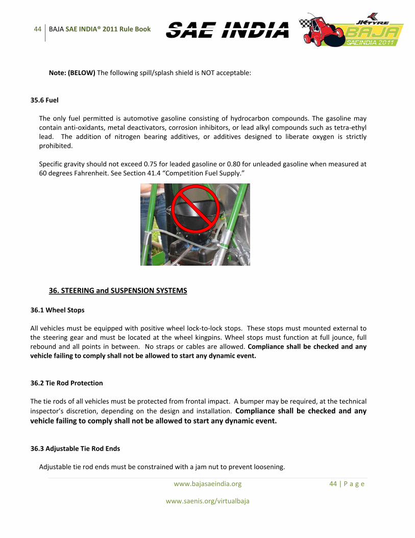
44 BAJA SAE INDIA® 2011 Rule Book
www.bajasaeindia.org 44 | P a g e
www.saenis.org/virtualbaja
Note: (BELOW) The following spill/splash shield is NOT acceptable:
35.6 Fuel
The only fuel permitted is automotive gasoline consisting of hydrocarbon compounds. The gasoline may contain anti‐oxidants, metal deactivators, corrosion inhibitors, or lead alkyl compounds such as tetra‐ethyl lead. The addition of nitrogen bearing additives, or additives designed to liberate oxygen is strictly prohibited. Specific gravity should not exceed 0.75 for leaded gasoline or 0.80 for unleaded gasoline when measured at 60 degrees Fahrenheit. See Section 41.4 “Competition Fuel Supply.”
36. STEERING and SUSPENSION SYSTEMS 36.1 Wheel Stops All vehicles must be equipped with positive wheel lock‐to‐lock stops. These stops must mounted external to the steering gear and must be located at the wheel kingpins. Wheel stops must function at full jounce, full rebound and all points in between. No straps or cables are allowed. Compliance shall be checked and any vehicle failing to comply shall not be allowed to start any dynamic event.
36.2 Tie Rod Protection The tie rods of all vehicles must be protected from frontal impact. A bumper may be required, at the technical inspector’s discretion, depending on the design and installation. Compliance shall be checked and any vehicle failing to comply shall not be allowed to start any dynamic event.
36.3 Adjustable Tie Rod Ends
Adjustable tie rod ends must be constrained with a jam nut to prevent loosening.

45 BAJA SAE INDIA® 2011 Rule Book
www.bajasaeindia.org 45 | P a g e
www.saenis.org/virtualbaja
36.4 Handlebar steering
Handlebar operated steering system is specifically prohibited.
37. Fasteners All fasteners in the engine, steering, suspension, braking (all calipers, all master cylinder mounting, and non OEM rotors & hub systems), throttle pedal and driver restraint systems must meet the following guidelines.
37.1 Fasteners
All fasteners used in the systems designated in Section 37 must be captive; defined as requiring NYLON locknuts, cottered nuts or safety wired bolts (in blind applications). Lock washers or thread sealant do not meet this requirement.
37.1.1 Lock Wire Procedure Detail
EXAMPLE: A team using a custom hub with an OEM rotor must meet the locking requirements, but a team using an OEM hub and OEM rotor would be exempt. The above figure illustrates the procedure for using lock wire: A. Above illustrations assume right hand threads. B. No more than three (3) bolts may be safe‐tied together. C. Bolt heads may be safe‐tied as shown only when the female thread receiver is captive, or the nuts meet previous lock nut requirements. D. Nuts (pre‐drilled) may be safe‐tied in similar fashion to the illustrations with the following conditions:
1. Nuts are heat‐treated. 2. Nuts are “factory drilled” for use with lock wire.
E. Lock wire MUST fill a minimum of 75% of the drilled hole provided for the use of lock wire. F. Lock wire must be aircraft quality stainless steel of .508 mm, .813mm, or 1.067mm diameter (0.020 inches, 0.032 inches, or 0.042 inches diameter). Diameter of lock wire is determined by the thread size of the fastener to be satisfied:
1. Thread sizes of ¼” and smaller use 0.020” wire. 2. Thread sized of ¼” to ½” use 0.032” wire. 3. Thread sizes > ½” use 0.042” wire.
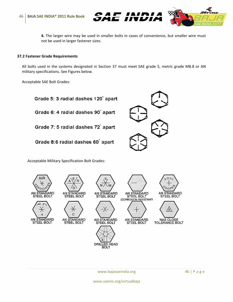
46 BAJA SAE INDIA® 2011 Rule Book
www.bajasaeindia.org 46 | P a g e
www.saenis.org/virtualbaja
4. The larger wire may be used in smaller bolts in cases of convenience, but smaller wire must not be used in larger fastener sizes.
37.2 Fastener Grade Requirements
All bolts used in the systems designated in Section 37 must meet SAE grade 5, metric grade M8.8 or AN military specifications. See Figures below. Acceptable SAE Bolt Grades:
Acceptable Military Specification Bolt Grades:
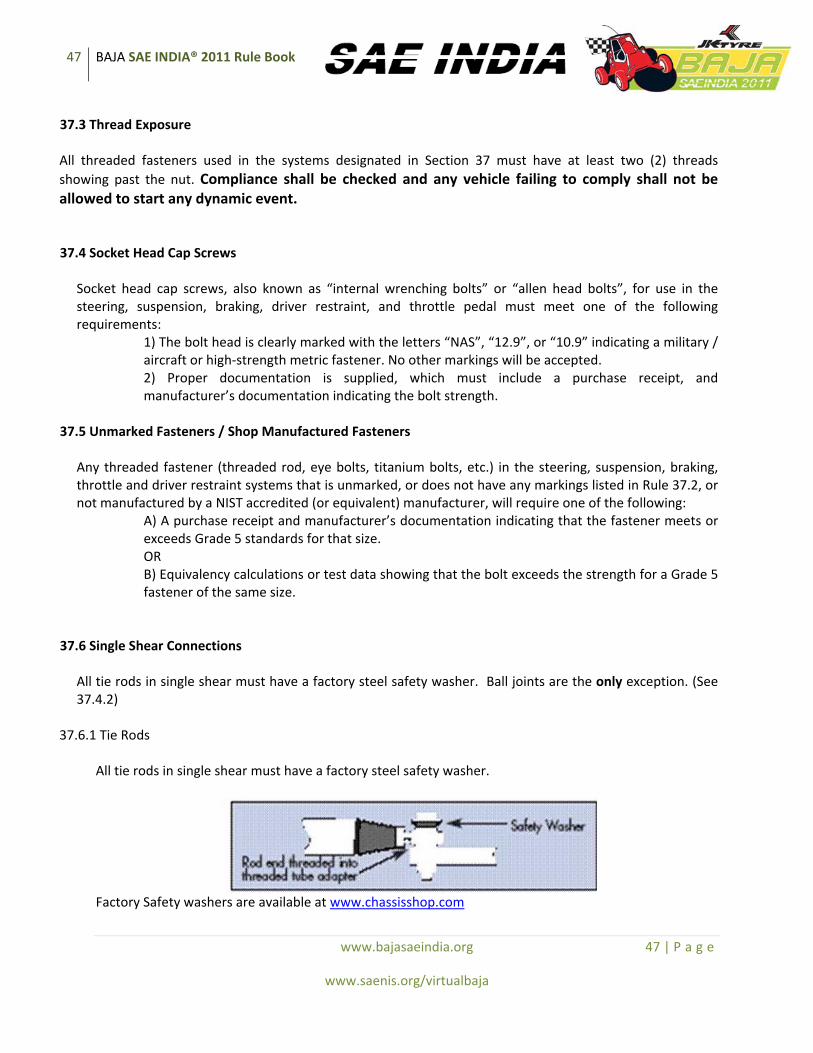
47 BAJA SAE INDIA® 2011 Rule Book
www.bajasaeindia.org 47 | P a g e
www.saenis.org/virtualbaja
37.3 Thread Exposure All threaded fasteners used in the systems designated in Section 37 must have at least two (2) threads showing past the nut. Compliance shall be checked and any vehicle failing to comply shall not be allowed to start any dynamic event.
37.4 Socket Head Cap Screws
Socket head cap screws, also known as “internal wrenching bolts” or “allen head bolts”, for use in the steering, suspension, braking, driver restraint, and throttle pedal must meet one of the following requirements:
1) The bolt head is clearly marked with the letters “NAS”, “12.9”, or “10.9” indicating a military / aircraft or high‐strength metric fastener. No other markings will be accepted. 2) Proper documentation is supplied, which must include a purchase receipt, and manufacturer’s documentation indicating the bolt strength.
37.5 Unmarked Fasteners / Shop Manufactured Fasteners
Any threaded fastener (threaded rod, eye bolts, titanium bolts, etc.) in the steering, suspension, braking, throttle and driver restraint systems that is unmarked, or does not have any markings listed in Rule 37.2, or not manufactured by a NIST accredited (or equivalent) manufacturer, will require one of the following:
A) A purchase receipt and manufacturer’s documentation indicating that the fastener meets or exceeds Grade 5 standards for that size. OR B) Equivalency calculations or test data showing that the bolt exceeds the strength for a Grade 5 fastener of the same size.
37.6 Single Shear Connections
All tie rods in single shear must have a factory steel safety washer. Ball joints are the only exception. (See 37.4.2)
37.6.1 Tie Rods
All tie rods in single shear must have a factory steel safety washer.
Factory Safety washers are available at www.chassisshop.com

48 BAJA SAE INDIA® 2011 Rule Book
www.bajasaeindia.org 48 | P a g e
www.saenis.org/virtualbaja
37.6.2 Ball Joints
Any commercially manufactured ball joints or rod ends with studs are allowed. Student manufactured ball joints or rod ends with studs are specifically prohibited.
38. GUARDS 38.1 Powertrain Guards All rotating parts such as belts, chains, and sprockets that rotate at the rate of the drive axle(s) or faster, must be shielded to prevent injury to the driver or bystanders should the component fly apart due to centrifugal force. These guards/shields must extend around the periphery of the belt or chain. They must be mounted with sound engineering practice, in order to resist vibration. They must be either (a) made of AISI 1010 steel at least 1.524 mm (0.06 inch) thick or (b) a material having equivalent energy absorption at rupture per unit width of shield. Equivalency calculations for the alternative material must meet the following requirements: All calculations must be shown in SI units. Calculations must use the following material properties for the 1010 steel: Yield Strength = 305 MPA, Ultimate Strength = 365 MPA, Elongation at Break = 20.0%, Modulus of Elasticity = 205 GPA. Documentation from the material manufacturer showing the Ultimate Strength, Elongation at Break, and Modulus of Elasticity of the alternative material must be provided. If a stress‐strain curve for the alternative material is not provided then it must be assumed that the stress strain curve is linear to the yield point and linear from the yield point to the ultimate strength, where strain = elongation at break (See Figure10). If a fiber reinforced composite material is used, then a stress strain curve must be provided for worst‐case tensile loading. Additionally, the curve for the composite material must be specific to the matrix and manufacturing methods used. Lastly, the minimum fiber reinforced composite material must be 3.175mm (.125 inch) thick. Compliance shall be checked and any vehicle failing to comply shall not be allowed to start any dynamic event.
In order to show equivalency the calculation must show the following: Area under curve for AISI 1010 Steel x Thickness < or = Area under curve for alternative material x Thickness
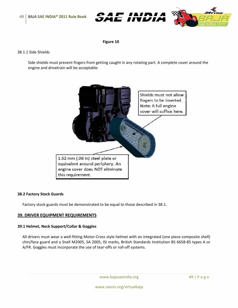
49 BAJA SAE INDIA® 2011 Rule Book
www.bajasaeindia.org 49 | P a g e
www.saenis.org/virtualbaja
Figure 10 38.1.1 Side Shields
Side shields must prevent fingers from getting caught in any rotating part. A complete cover around the engine and drivetrain will be acceptable.
38.2 Factory Stock Guards
Factory stock guards must be demonstrated to be equal to those described in 38.1. 39. DRIVER EQUIPMENT REQUIREMENTS 39.1 Helmet, Neck Support/Collar & Goggles
All drivers must wear a well‐fitting Motor‐Cross style helmet with an integrated (one piece composite shell) chin/face guard and a Snell M2005, SA 2005, ISI marks, British Standards Institution BS 6658‐85 types A or A/FR. Goggles must incorporate the use of tear‐offs or roll‐off systems.
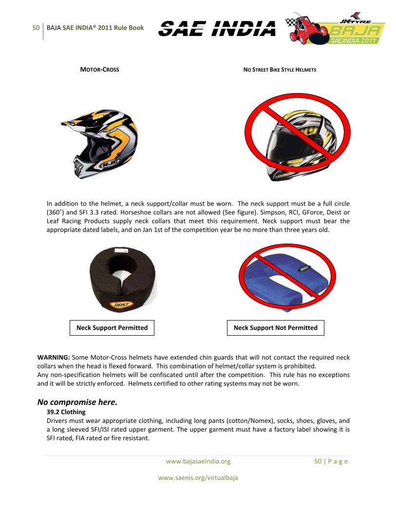
50 BAJA SAE INDIA® 2011 Rule Book
www.bajasaeindia.org 50 | P a g e
www.saenis.org/virtualbaja
MOTOR‐CROSS NO STREET BIKE STYLE HELMETS
In addition to the helmet, a neck support/collar must be worn. The neck support must be a full circle (360˚) and SFI 3.3 rated. Horseshoe collars are not allowed (See figure). Simpson, RCI, GForce, Deist or Leaf Racing Products supply neck collars that meet this requirement. Neck support must bear the appropriate dated labels, and on Jan 1st of the competition year be no more than three years old.
WARNING: Some Motor‐Cross helmets have extended chin guards that will not contact the required neck collars when the head is flexed forward. This combination of helmet/collar system is prohibited. Any non‐specification helmets will be confiscated until after the competition. This rule has no exceptions and it will be strictly enforced. Helmets certified to other rating systems may not be worn.
No compromise here. 39.2 Clothing Drivers must wear appropriate clothing, including long pants (cotton/Nomex), socks, shoes, gloves, and a long sleeved SFI/ISI rated upper garment. The upper garment must have a factory label showing it is SFI rated, FIA rated or fire resistant.
Neck Support Permitted Neck Support Not Permitted
51 BAJA SAE INDIA® 2011 Rule Book
www.bajasaeindia.org 51 | P a g e
www.saenis.org/virtualbaja
SECTION 4 COMPETITION PROCEDURES AND REGULATIONS
40. RULES CLARIFICATION AND PROTESTS 40.1 Technical Questions
Questions about the rules requirements and restrictions must be submitted by e‐mail to the Technical Inspectors of the Baja SAE India for any queries / interpretations. Technical questions are to be emailed to the Technical Committee at: [email protected]. Questions and answers will be posted on the Baja SAE India website at: www.bajasaeindia.org. Teams are advised that the technical inspection / approval of any vehicle, including those constructed based on responses to rules questions, is contingent on the proper fabrication of the vehicle and its design as an integrated unit. NOTE: Please keep in mind that final operating approval of a Baja SAE India vehicle can only be given at the competition venue by the National Technical Inspectors.
40.2 Protests
It is recognized that hundreds of hours of work have gone into fielding a vehicle. In the heat of competition, emotions peak and disputes can arise. The organizers and SAE India staff will make every effort to fully review all questions and resolve problems quickly and equitably.
40.2.1Preliminary Review – Required
If a team has a question about scoring, judging, policies or any official action it must be brought to the notice of the organizers or SAE INDIA staff’s attention for an informal preliminary review before a protest can be filed.
40.2.2 Cause for Protest
A team may protest any rule interpretation, score or official action (unless specifically excluded from protest) which they feel has caused some actual, non‐trivial, harm to their team, or has had a substantive effect on their score. Teams may not protest rule interpretations or actions that have not caused them any substantive damage.
40.2.3 Protest Format and Forfeit
All protests must be filed in writing and presented to the organizer or SAE staff by the faculty advisor or team captain. In order to have a protest considered, a team must post a twenty‐five (25) point protest bond which will be forfeited if their protest is rejected.
40.2.4 Protest Period

52 BAJA SAE INDIA® 2011 Rule Book
www.bajasaeindia.org 52 | P a g e
www.saenis.org/virtualbaja
Protests concerning any aspect of the competition must be filed within one hour (60 minutes) of the end of the event to which the protest relates.
40.2.5 Decision
The decision of the competition protest committee or National Technical Inspectors regarding any protest is final.
41. COMPETITION Procedures and Regulation GENERAL 41.1 Drivers Meetings
All team members identified as drivers and their support personnel MUST attend all drivers meetings. Attendance at drivers meeting is mandatory. Failure to attend drivers meetings can result in disqualification of members or the entire team.
41.2 Pre‐inspection Operation Prohibited
Vehicles may not be started or driven prior to passing technical inspection, except as required as part of the inspection process itself.
41.3 Governor Setting Lombardini Technical Representatives will set the governors of all vehicles. Vehicles must be presented for governor setting with (1) the drivetrain disconnected, (2) the engine shaft clear and (3) the throttle cable unhooked from the engine. Baja SAE India Officials may order a recheck of the governor setting of any vehicle at any time.
41.4 Competition Fuel Supply
Fuel at the competition will either (1) be provided by the organizers or (2) the organizers will specify acceptable fuel providers.
41.4.1 Refuelling
All refueling of the cars done in the pit area or on the course must be done with (1) the engine shut‐off and (2) the driver out of the car. Any violations of this rule will be subjected to severe penalties. A fire extinguisher must be on hand whenever a vehicle is being refueled.
41.5 Engine and Drivetrain Inspection
The Technical Inspectors reserve the right to impound and inspect any vehicle during the dynamic or endurance events. Any vehicle found to have: (1) a drivetrain configuration not matching the Drivetrain Certification Form submitted during technical inspection or (2) an engine in violation of rules sections 21.4 through 21.4.14.4, 21.5, 21.6 shall receive zero (0) for all dynamic competition events completed during the day on which the inspection was performed.

53 BAJA SAE INDIA® 2011 Rule Book
www.bajasaeindia.org 53 | P a g e
www.saenis.org/virtualbaja
At the end of the endurance event, the top ten (10) vehicles will be impounded. Some or all of these vehicles will be inspected. Any vehicle found to have a modified engine or drivetrain will be disqualified from the entire competition. The organizers reserve the right to impound and inspect any vehicle. No one except technical inspectors and officials are permitted in the impound area without specific authorization from the organizers. NO EXCEPTIONS.
41.6 Engine Recall Option
The organizers and SAE India may, at their sole option, recall the engine from any vehicle in the competition in exchange for a new Lombardini engine. Recalled engines will not be returned and will be inspected at Lombardini’s facilities to confirm compliance with the rules.
41.7 Pit Rules 41.7.1 Vehicle Movement – Walking Pace Required
When a vehicle is driven anywhere except the practice area or competition events, it must move at walking speed with a team member walking along side at a normal walking pace. During the performance events when the excitement is high, it is particularly important that vehicles be moved at a walking pace in the pits. The walking speed rule will be strictly enforced and point penalties will be assessed for violations, including impounding the vehicle for a specific period of time, at the discretion of the Technical Inspectors. Under no circumstances may anyone other than the driver ride on a vehicle.
41.7.2 Team’s Work Area
The team’s work area should be clearly defined and should be kept uncluttered at all times. When a team leaves their area, it must be left clean.
41.7.3 Vehicles in the Pits
Only the Baja SAE India vehicles themselves and the teams’ support trucks and trailers are allowed in the pits. Team members may not operate bicycles, skateboards, scooters, motorcycles, quads or other person carrying or motor propelled vehicles in the pits or competition areas.
41.7.4 Occupancy Restrictions
The organizers, at their sole discretion, may limit the pits to team members, faculty advisors and competition officials.
54 BAJA SAE INDIA® 2011 Rule Book
www.bajasaeindia.org 54 | P a g e
www.saenis.org/virtualbaja
41.8 Driving Restrictions
During the competition, Baja SAE India vehicles may only be driven between the pits and an event site, during official practice or in the events themselves. DRIVING OFF‐SITE IS ABSOLUTELY PROHIBITED. TEAMS FOUND TO HAVE DRIVEN THEIR VEHICLE AT AN OFF‐SITE LOCATION MAY BE EXPELLED FROM THE COMPETITION.
41.9 Loopholes
It is virtually impossible for a set of rules to be so comprehensive that it covers all possible questions about the vehicle’s design parameters or the conduct of the competition. Please keep in mind that safety remains paramount during Baja SAE India, so any perceived loopholes should be resolved in the direction of increased safety/ concept of the competition.
41.10 Penalties
Organizers have the right to modify the penalties listed in the various dynamic event descriptions to better reflect the design of their event courses, the course lengths or any special conditions unique to the site. The standard dynamic event penalties in these rules are default values that will be applied unless there is a change by the organizer.
42. Rules of Conduct 42.1 Sportsmanship
All Baja SAE INDIA participants can be proud of the excellent sportsmanship and cooperation among teams that are two of the hallmarks of the series. Good conduct and compliance with the rules and the official instructions are expectations and requirements for every team member. On those extremely rare occasions where there is an incident of unsportsmanlike conduct the organizer is authorized to impose an appropriate penalty. Unsportsmanlike conduct can include arguments with officials, disobedience of official instructions and the use of abusive or threatening language to any official or other participant. Depending on the seriousness of the infraction the penalty for such actions can range from a deduction of up to fifty percent (50%) of the team’s points to expulsion of the entire team. Penalties of this type will only be imposed after a complete review of the incident by the organizer and SAE India staff.
42.2 Alcohol and Illegal Material
Alcoholic beverages, firearms, weapons of any type and illegal materials are prohibited at the Baja SAE India site during the competition. The penalty for violation of this rule is the immediate expulsion of the entire team, not just the individual(s) involved. This rule applies to team members, advisors and any individuals working with the team on‐site.

55 BAJA SAE INDIA® 2011 Rule Book
www.bajasaeindia.org 55 | P a g e
www.saenis.org/virtualbaja
42.3 Parties
Disruptive parties either on or off‐site should be prevented by the faculty advisor.
42.4 Trash Clean‐up
Clean‐up of trash and debris is the responsibility of the teams. Please make an effort to keep your pit area clean and uncluttered. At the end of the day, each team must clean their work area.
42.5 Site Condition
Please help the organizers keep the site clean. The sites used for Baja SAE INDIA are Government property and should be treated as such. Competitors are reminded that they are guests of the owners. All trash should be placed in the receptacles provided. Glass is not allowed on the grounds. Failure to clean the premises will result in an unsportsmanlike conduct penalty. Competitors are encouraged to police their areas after meals.
43. Spectator Rules 43.1 General
The organizers typically do not have a direct line of communication with spectators other than on‐the‐spot at the competition; thus, the competitors, faculty and volunteers are expected to help inform the spectators of the safety rules and help restrict spectators to the spectator areas.
43.2 Alcoholic Beverages
Spectators may not drink alcoholic beverages at any event location.
43.3 Access Restrictions
Spectators must keep well back from the event and practice tracks and from any area where vehicles are operating under power. Motor vehicle competitions are potentially dangerous and safety rules will be strictly enforced.
43.4 Children
A competition site is not a safe place for children and unsupervised young people. Spectators who fail to strictly control their children will be asked to leave the site.
43.5 Removal of Spectators
The course officials and organizers have the absolute right to restrict spectator access to any parts of the site and to eject anyone who violates safety rules or ignores the instructions of officials.

56 BAJA SAE INDIA® 2011 Rule Book
www.bajasaeindia.org 56 | P a g e
www.saenis.org/virtualbaja
44. UNSAFE Practices & CONDUCT
All participants are required to exercise safe practices and avoid unsafe activities at all times during the competition. The event organizer has the discretionary authority to impose a just penalty for any conduct deemed unsafe. All team members will be held to this rule.
45. Miscellaneous 45.1 Driver Equipment
Drivers must wear all of the equipment specified in Section 39 “Driver Equipment Requirements" and a properly fastened restraint system at all times when the vehicle is running in any event or on the test track. Drivers not wearing the proper equipment will not be permitted to drive, and may have their competition driver’s privileges revoked. Seatbelts, helmets, goggles, wrist restraints, and the required clothing must be worn at all times a driver is operating a vehicle
45.2 Practice Area
Practice may only take place in designated areas. Practicing outside of the designated practice area will result in a minimum fifty (50) point penalty and/or the revocation of driving privileges depending on the extent of the infraction.
46. Safety – Team Responsibility
Safety is the primary consideration in the design of Baja SAE India vehicles and the conduct of the competitions. Teams need to include safety considerations in all parts of their program. At all performance events, it is the responsibility of the team to ensure both the vehicle and driver meet and follow all the requirements and restrictions of the rules.
Note: The teams are required to maintain the code of conduct throughout the event, failing which they may have to face point penalties or even disqualification.
Note: All teams, spectators and faculty members are responsible for the safety of their own, their vehicles and belongings. No claims regarding these shall be entertained by the organizers.
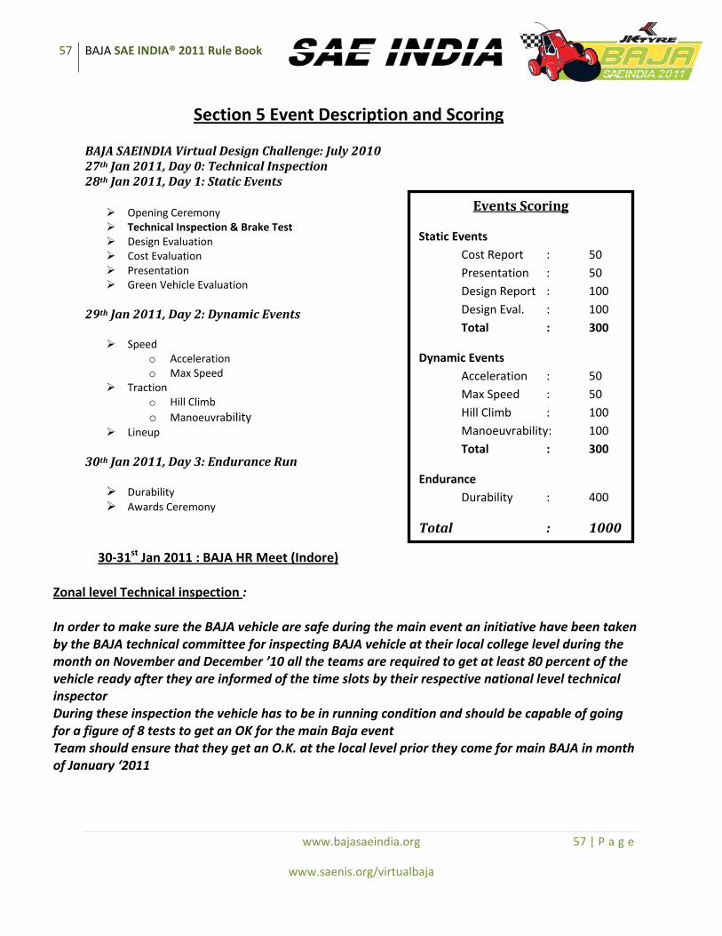
57 BAJA SAE INDIA® 2011 Rule Book
www.bajasaeindia.org 57 | P a g e
www.saenis.org/virtualbaja
Section 5 Event Description and Scoring
BAJA SAEINDIA Virtual Design Challenge: July 2010 27th Jan 2011, Day 0: Technical Inspection 28th Jan 2011, Day 1: Static Events
Opening Ceremony Technical Inspection & Brake Test Design Evaluation Cost Evaluation Presentation Green Vehicle Evaluation
29th Jan 2011, Day 2: Dynamic Events
Speed o Acceleration o Max Speed
Traction o Hill Climb o Manoeuvrability
Lineup
30th Jan 2011, Day 3: Endurance Run
Durability Awards Ceremony
30‐31st Jan 2011 : BAJA HR Meet (Indore) Zonal level Technical inspection : In order to make sure the BAJA vehicle are safe during the main event an initiative have been taken by the BAJA technical committee for inspecting BAJA vehicle at their local college level during the month on November and December ’10 all the teams are required to get at least 80 percent of the vehicle ready after they are informed of the time slots by their respective national level technical inspector During these inspection the vehicle has to be in running condition and should be capable of going for a figure of 8 tests to get an OK for the main Baja event Team should ensure that they get an O.K. at the local level prior they come for main BAJA in month of January ‘2011
Events Scoring
Static Events Cost Report : 50 Presentation : 50 Design Report : 100 Design Eval. : 100 Total : 300
Dynamic Events Acceleration : 50 Max Speed : 50 Hill Climb : 100 Manoeuvrability: 100 Total : 300
Endurance Durability : 400
Total : 1000
58 BAJA SAE INDIA® 2011 Rule Book
www.bajasaeindia.org 58 | P a g e
www.saenis.org/virtualbaja
51. On‐site Technical inspection The objectives of technical inspection are to (1) ensure the safety of the vehicles and therefore the competition as much as humanly possible, (2) teach the participants that they must pay attention to the fine details once they get out into industry to produce a safe, competitive, low cost, and/or quality product, and (3) provide a positive learning experience for all participants. 51.1 Technical Inspection ‐ Pass/Fail – Point Deduction
All Baja SAE India vehicles must pass a technical inspection before they are permitted to operate under power. The inspection will determine if the vehicle satisfies the requirements and restrictions of the Baja SAE India rules. The exact procedures and instruments used for inspection and testing are entirely at the discretion of the Technical Inspectors. Decisions of the technical inspectors concerning vehicle compliance are final and may not be appealed. Vehicles are to arrive at technical inspection in ready to run condition
with all drivers present, safety equipment and documentation. This is compulsory. If vehicles are not ready for technical inspection when they arrive, they may receive a point deduction. Faculty advisors are not allowed to participate during technical inspection. The team captain or other designated members of the team shall do all the presenting. All vehicles that do not pass technical inspection by the end of the Static Events will receive a score of zero (0) points. Vehicles that do not pass Technical Inspection at the first attempt at the site may be penalized.
Note: The teams are required to perform a conformance check on their vehicle. The vehicle must pass the checks stated in the technical inspection data sheet. The teams are required to fabricate their vehicle in accordance with these requirements.
Technical inspection will consist of three (3) separate parts as follows: Part 1 – Engine inspection and governor setting Each vehicle must arrive at Engine inspection with the output shaft bare, and working Kill Switches. Each vehicle engine must be inspected by Lombardini technical staff that will (1) confirm its compliance with the rules and (2) set the governor to the specified rpm. Part 1 must be passed before a team may apply for Part 2 or Part 3 inspection. Part 2 – Technical inspection and scrutinizing Each vehicle will be inspected to determine if it complies with the requirements and restrictions of the Baja SAE India rules. This inspection will include an examination of the driver’s equipment including helmet and arm restraints and a test of driver exit time. Each team must bring the following items to inspection, if they do not have the items at the time of inspection they will receive a 10pt deduction for each item missing or not completely filled out: (a) Frame Material Documentation: Receipts documenting the materials purchased, or otherwise acquired, and used to build the frame.
59 BAJA SAE INDIA® 2011 Rule Book
www.bajasaeindia.org 59 | P a g e
www.saenis.org/virtualbaja
(b) Roll Cage Specification Sheet: A completed copy of the Roll Cage Specification Sheet. (See Section 6 Appendix) (c) Technical Inspection Sheet: A duly filled in completed Technical Inspection Sheet. (See 51.1.2) (d) Drive Train Check Sheet: A properly completed Drive Train Check Sheet is required at technical inspection. (e) Drivers Present: All drivers must be present at technical inspection
Part 2 must be passed before a team may apply for Part 3 inspection.
Part 3 – Kill switch and dynamic brake testing Both the external and cockpit kill switches will be tested for functionality. If both switches pass the test then the vehicle will be dynamically brake tested . Each vehicle must demonstrate its ability to lock all four wheels and come to rest in an approximately straight line after acceleration run specified by the inspectors. If a vehicle fails to pass any part of the inspection it must be corrected/modified and brought into compliance with the rules before it is permitted to operate. The inspectors and officials have the right to re‐inspect any vehicle at any time during the competition and require correction of any non‐compliance.
51.1.1 Inspection Stickers
A multi‐part inspection sticker will be issued in sections to the team as each of the three parts of technical inspection is completed. The inspectors will place the inspection sticker in a prominent location of their choice. The inspection sticker must remain on the vehicle throughout the competition. Vehicles without all parts of the inspection sticker may not be allowed to be operated under power. Technical inspectors and officials may remove any or all parts of the inspection sticker from any vehicle that has been damaged or which they reasonably believe may not comply with the rules.
51.1.2 Technical Inspection Sheet – Pre‐inspection Required
Before bringing their car to technical inspection each team must (1) pre‐inspect the vehicle for compliance with the rules, (2) complete the official technical inspection sheet (available on the Baja SAE India Website) (3) have the completed inspection list signed by the faculty advisor and team captain. Teams should download the most current version of the technical inspection sheet within two weeks of the competition and thoroughly inspect their vehicle in accordance with the sheet. All drivers must be at technical inspection or they will be removed from the list of drivers and a 10 point penalty will be applied to the team. NOTE: Teams presenting Technical Inspection Sheets that are (1) incomplete, (2) inaccurate (i.e. do not correspond to the actual condition of the car) (3) are found to have more than 3 items not in accordance with the rules, or (4) do not represent a serious effort at pre‐inspection will be denied inspection at that
60 BAJA SAE INDIA® 2011 Rule Book
www.bajasaeindia.org 60 | P a g e
www.saenis.org/virtualbaja
time and sent back to the end of the inspection line with a 15 point deduction / other penalties which shall be prominently displayed at the site at least 60minutes before commencement of Technical Inspection of the first vehicle.
51.1.3 “As‐approved” Condition
Once a vehicle has passed technical inspection its configuration may not be modified. Approved vehicles must remain in “as‐approved” condition throughout the competition. Necessary repairs that do not significantly change the configuration of the vehicle are permitted. Minor adjustments permitted by the rules and normal vehicle maintenance and tuning are not considered modifications. Note: It is important for every team to get their vehicle approved by the technical scrutiny during which the safety, integrity of vehicle structure, fabrication processes adopted, etc will be judged. The team shall provide documented proof of fabrication process of every component and the design analysis, failing which they may have to face point penalties or disqualification. THE BAJA SAEINDIA TECHNICAL COMMITTEE RESERVES THE RIGHT TO DISALLOW ANY VEHICLE FAILING TO COMPLY WITH THE REQUIREMENT OF THESE RULES TO TAKE PART IN ANY DYNAMIC EVENT TILL THE VEHICLE IN QUESTION IS RECTIFIED, REPRESENTED AND PASSES THE TECHNICAL INSPECTION. FOR THIS COMPLIANCE, MAXIMUM NUMBER OF RE‐INSPECTIONS PER VEHICLE (BESIDES THE NORMAL INSPECTION AT SITE) SHALL BE 2. THIS REQUIREMENT SHALL BE ENSURED WITHOUT EXCEPTION. THEREFORE, IT IS REQUIRED THAT TEAMS COME WITH THEIR VEHICLES WELL PREPARED FOR THE EVENT, TO AVOID DISAPPOINTMENT.
52. Static events and required reports – total 300 points 52.1 Engineering Design
Engineering design assessment consists of two events: Design Report and Design Evaluation.
52.1.1 Design Report: 100 Points
The design report should clearly explain the engineering and design process that was used in developing each system of the team’s Baja vehicle. The process for each system could include: Objectives, customer requirements, alternatives considered (e.g. independent rear suspension vs. single rear swing arm, manual transmission vs. CVT, etc.), improvements over last year’s design, the result(s) of design calculations, stress analysis, testing, etc. The design analysis and its results should be clearly mentioned in the report and any ambiguity if found may result in penalties.
52.1.2 Design Report – Format
(a) Format – The format for the design report would be made available online at the Baja SAE India Website. Each team shall follow the specified format only

61 BAJA SAE INDIA® 2011 Rule Book
www.bajasaeindia.org 61 | P a g e
www.saenis.org/virtualbaja
(b) Electronic version – The design report must be submitted electronically in Adobe Acrobat Format. The document must be a single file (text, drawings and optional content are all inclusive).The design report file must be named as follows: Car #_college name team name EXAMPLE: Car #18_Netaji Subhas Institute of Technology_NSIT RACERS
52.1.3 Design Report ‐ Page Limit
The technical paper segment of design report is limited to ten (10) pages, including the cover page. Additionally the report may, at the team’s option, include up to four (4) non‐text, pages of plans, graphics, photographs or other data for a maximum of fourteen (14) pages of information. The only text permitted on the four (4) optional pages is captions. All pages must be either 8 ½ “x 11” or A4. NOTE: If your paper exceeds 10 pages of technical report or 4 pages of graphics, then only the first 10 technical and 4 graphic pages will be evaluated.
52.1.4 Design Report – Deadline and Submission
Design reports must be received no later than the due date. Any Design Report not received by the due date will be subject to a penalty of ten (10) points for each day after the deadline. Teams that do not submit a Design Report will not be judged in either part of the Design Event and will receive zero (0) points. Electronic Report: Email the electronic version of the design report to each competition your team has entered by the submission date. Email addresses will be listed in the Baja SAE India website. COMMENT: We recommend that you bring a printed copy of your design report to the competition and proof of submission.
52.1.5 Design Evaluation: 100 Points
Design Evaluation will be conducted at the event site on the first full day of the competition. Cars are expected to be presented for Design Evaluation in essentially finished condition, i.e. fully assembled, complete and ready‐to‐run. Vehicles presented in an unfinished condition may receive lower, or zero points for any incomplete areas that cannot be fully assessed by the design judges. Additionally, the judges have the right to refuse to evaluate incomplete vehicles. Teams that are refused judging because of incompleteness will receive zero points for Design Evaluation.
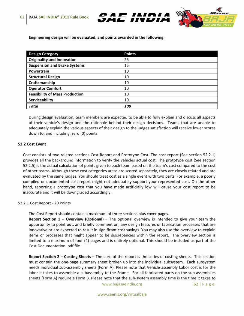
62 BAJA SAE INDIA® 2011 Rule Book
www.bajasaeindia.org 62 | P a g e
www.saenis.org/virtualbaja
Engineering design will be evaluated, and points awarded in the following:
Design Category Points Originality and Innovation 25 Suspension and Brake Systems 15 Powertrain 10 Structural Design 10 Craftsmanship 10 Operator Comfort 10 Feasibility of Mass Production 10 Serviceability 10 Total 100 During design evaluation, team members are expected to be able to fully explain and discuss all aspects of their vehicle’s design and the rationale behind their design decisions. Teams that are unable to adequately explain the various aspects of their design to the judges satisfaction will receive lower scores down to, and including, zero (0) points.
52.2 Cost Event
Cost consists of two related sections Cost Report and Prototype Cost. The cost report (See section 52.2.1) provides all the background information to verify the vehicles actual cost. The prototype cost (See section 52.2.5) is the actual calculation of points given to each team based on the team’s cost compared to the cost of other teams. Although these cost categories areas are scored separately, they are closely related and are evaluated by the same judges. You should treat cost as a single event with two parts. For example, a poorly compiled or documented cost report might not adequately support your represented cost. On the other hand, reporting a prototype cost that you have made artificially low will cause your cost report to be inaccurate and it will be downgraded accordingly.
52.2.1 Cost Report ‐ 20 Points
The Cost Report should contain a maximum of three sections plus cover pages. Report Section 1 – Overview (Optional) – The optional overview is intended to give your team the opportunity to point out, and briefly comment on, any design features or fabrication processes that are innovative or are expected to result in significant cost savings. You may also use the overview to explain items or processes that might appear to be discrepancies within the report. The overview section is limited to a maximum of four (4) pages and is entirely optional. This should be included as part of the Cost Documentation .pdf file. Report Section 2 – Costing Sheets – The core of the report is the series of costing sheets. This section must contain the one‐page summary sheet broken up into the individual subsystem. Each subsystem needs individual sub‐assembly sheets (Form A). Please note that Vehicle assembly Labor cost is for the labor it takes to assemble a subassembly to the Frame. For all fabricated parts on the sub‐assemblies sheets (Form A) require a Form B. Please note that the sub‐system assembly time is the time it takes to

63 BAJA SAE INDIA® 2011 Rule Book
www.bajasaeindia.org 63 | P a g e
www.saenis.org/virtualbaja
assemble all the parts in that assembly together. Report Section 3 – Cost Documentation – Include copies of receipts, invoices, price tags, catalogue pages, on‐line prices, or such other documentation as you choose to substantiate the costs of the parts and material that you included in your costing sheets. This cost documentation must be at full retail Indian prices. The report is expected to be comprehensive, well documented, truthful and accurate.
Note: Each team is required to bring the bills of the manufacturing cost/cost of purchased components at the event. The team leader will be questioned about the costing and the points will be awarded on the basis of accurate reporting of costs. 52.2.2 Cost Report – Electronic Format
Electronic version – The cost report must be submitted electronically in two different documents: 1) The Microsoft Excel format (with the extension .xls), using the supplied template posted on the Baja SAE Important Documents page. This document may not be modified from its current form. This includes password protecting and embedding macros. Teams will receive zero (0) points for Cost if the report is in the incorrect format or the files have been modified 2) A PDF file with all of the cost documentation described above. The cost report file must be named as follows: college name (full name), team name (If more than one vehicle is entered).
52.2.3 Penalty for Late or Non‐Submission
Cost reports arriving after the deadline will be penalized ten (10) points per day up to a maximum of one hundred (100)‐points. Failure to submit a cost report will result in a one hundred (100) point penalty. Also, note that the maximum penalty for late or non‐submission exceeds the total number of points for the event. COMMENT: It is the responsibility of the team to verify when the report was received by SAE, submission time will be the time the report is received at SAE. Teams will be cost audited at competition. If they do not have a hard copy of their cost report, they will receive zero points for the cost of their car. It is recommended that teams bring electronic copies of their cost report and documentation showing submittal date to all competitions.
52.2.4 Cost Judges Authority
The judges have the authority to increase your costs and/or fabrication times if they believe that the figures you have submitted are below current prices for the item, source, or process involved. Prices or times that are higher than the judge would have expected will not be corrected. Mathematical errors will be penalized. Reports that are highly inaccurate, or in which the costs cannot be substantiated, may be rejected in their entirety and zero (0) points awarded for Cost.
52.2.5 Prototype Cost ‐ 30 points
Prototype cost is scored on the cost, as corrected by the judges, to produce the finished vehicle brought to the competition.
64 BAJA SAE INDIA® 2011 Rule Book
www.bajasaeindia.org 64 | P a g e
www.saenis.org/virtualbaja
Your prototype cost score will be calculated as follows: Prototype cost score = 30 x [(Max Cost – Your Cost)/ (Max Cost – Lowest Cost)] Where: “Your Cost” is your the cost as corrected by the cost judges, “Lowest Cost” is the corrected cost of the team producing the lowest cost vehicle and “Max Cost” is the corrected cost of team producing the highest cost vehicle.
52.3 Presentation: 50 Points 52.3.1 Presentation ‐ Objective
The objective of the Presentation is for the team to convince the “executives” of a hypothetical manufacturing company to purchase your team’s Baja vehicle design and put it into production at the rate of 4000 units per year. For the purposes of the presentation you may assume that the judges are a mixed group of corporate executives who may have experience in marketing, production, and finance as well as engineering.
52.3.2 Presentation ‐ Format
One or more team members may make the presentation to the judges. The presentation itself is limited to a maximum of ten (10) minutes. Following the presentation there will be an approximately five (5) minute question period. Only the judges are permitted to ask questions. Any team member on the presentation floor/stage may answer the questions even if that member did not speak during the presentation itself.
52.3.2.1 Projection Equipment
Teams planning to use data projection are responsible for bringing, or otherwise arranging for, their own data projectors. Some data projectors may be provided by the organizers; however teams should not rely on either the availability or functionality of such equipment.
52.3.3 Presentation – Scoring
The presentation event will be scored based on such categories as (1) the content of the presentation, (2) the organization of the presentation, (3) the effectiveness of the visual aids, (4) the speaker’s delivery, and (5) the team’s responses to the judge’s questions. Your score will be the average of your individual judge’s scores. The team that makes the best presentation will receive the highest score regardless of the finished quality of their actual vehicle.
53. Dynamic Events ‐ Total ‐ 700 Points The dynamic events are intended to determine how the Baja SAE India vehicles perform under a variety of conditions. Please note that the organizers have the right to modify the dynamic events to address local conditions, weather or resources.
65 BAJA SAE INDIA® 2011 Rule Book
www.bajasaeindia.org 65 | P a g e
www.saenis.org/virtualbaja
53.1 Speed Events 53.1.1 Acceleration: 100 Points
53.1.1.1 Acceleration ‐ Objective
Acceleration determines the time it takes the vehicle to accelerate along 100 ft (30.48 m) or 150 ft (45.72m) flat course. The choice of course length is at the organizer’s discretion.
53.1.1.2 Acceleration – Procedure
Each team may make two (2) attempts. Scoring will be based on the better of the two attempts. Timing may be done using either electronic systems or stop watches.
53.1.1.3 Acceleration– Penalties
The organizer has the right to modify the penalties imposed for different violations to account for differences in the length or design of specific event courses. False Start or Stall at Start First ‐ Rerun at end Second ‐ Run disqualification Leaving Course Run disqualification
53.1.1.4 Acceleration ‐ Scoring
Teams with Acceleration times that are more than twice that of the fastest car will not receive a score for this event. Teams attempting the event, but exceeding the time limit will be classified as “Excess Time”. The following equation will be used for the acceleration score: Acceleration score = 100 x [(T longest–T yours)/(T longest–T shortest)]
Where: “T shortest” is the fastest time by any team “T longest” is either (a) the slowest time by any team or (b) 2x the fastest time whichever is the shorter interval. “T yours” is your team’s best time
53.2 Traction Event: 100 Points
The traction events are designed to demonstrate the vehicle’s ability to use its traction to accomplish various tasks. At the organizer’s discretion, the traction event will be either the hill climb or a pulling event.
53.2.1 Hill Climb: 100 Points
53.2.1.1 Hill Climb – Objective
Hill climb assesses each vehicle’s ability to ascend a steep grade from a standing start.
53.2.1.2 Hill Climb – Procedure
66 BAJA SAE INDIA® 2011 Rule Book
www.bajasaeindia.org 66 | P a g e
www.saenis.org/virtualbaja
Each vehicle may make two (2) climbing attempts with the best distance or the fastest completion time counting for score. Once the vehicle stops moving forward the attempt is over and the attempt is scored for distance at that point. Vehicles may not continue the attempt after they have stopped on the course. If a vehicle stalls before reaching the top of the hill, or if its wheels are spinning without moving the vehicle forward, the attempt is scored for distance at that point.
53.2.1.3 Hill Climb Event – Penalties
The organizer has the right to modify the penalties imposed for different violations to account for differences in the length or design of specific event courses.
Leaving Course Score as maximum progress in feet at point upon exiting False Start First ‐ Rerun at end
Second ‐ Run disqualification
53.2.1.4 Hill Climb – Scoring
Method A: “Everyone Climbs the Hill”– If all teams succeed in completing a full climb, then the score will be based on the time of the climb and calculated by the following formula: Hill Climb Score = 100 x [(T longest – T yours)/( T longest – T shortest)]
Where: “T longest” is the longest time by any team “T shortest” is the shortest time by any team “T yours” is your team’s best time Method B: “No One Climbs the Hill”‐ If no vehicles succeed in climbing the hill, then the score will be based on the distance each team climbs as determined by the following formula: Hill Climb Score = 100 x [(D yours – D shortest)/(D longest – D shortest)]
Where: “D shortest” is the shortest distance climbed by any team. “D longest” is the longest distance climbed by any team. “D yours” is your team’s best climb.
Method C: “Some Teams Make the Climb” ‐ Where (a) at least one team makes the climb while (b) other teams do not, then the vehicles making the climb (Group I) will be scored based on time and the vehicles that stop on the hill (Group II) will be scored based on distance traveled. Scoring will be by the following formulas:
Group I – Teams that complete the climb will be scored by the following:
Group I Score = 100 x (T fastest/ T yours)
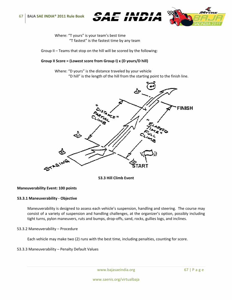
67 BAJA SAE INDIA® 2011 Rule Book
www.bajasaeindia.org 67 | P a g e
www.saenis.org/virtualbaja
Where: “T yours” is your team’s best time “T fastest” is the fastest time by any team
Group II – Teams that stop on the hill will be scored by the following: Group II Score = (Lowest score from Group I) x (D yours/D hill)
Where: “D yours” is the distance traveled by your vehicle “D hill” is the length of the hill from the starting point to the finish line.
53.3 Hill Climb Event Maneuverability Event: 100 points 53.3.1 Maneuverability ‐ Objective
Maneuverability is designed to assess each vehicle’s suspension, handling and steering. The course may consist of a variety of suspension and handling challenges, at the organizer’s option, possibly including tight turns, pylon maneuvers, ruts and bumps, drop‐offs, sand, rocks, gullies logs, and inclines.
53.3.2 Maneuverability – Procedure
Each vehicle may make two (2) runs with the best time, including penalties, counting for score.
53.3.3 Maneuverability – Penalty Default Values
68 BAJA SAE INDIA® 2011 Rule Book
www.bajasaeindia.org 68 | P a g e
www.saenis.org/virtualbaja
The organizer has the right to modify the penalties imposed for different violations to account for differences in the length or design of specific event courses.
Obstacle/Pylon moved 2 seconds Missed gate* 10 seconds Deliberate course violation Run disqualification False Start First ‐ Rerun at end
Second ‐ Run disqualification *Missed gate is when 2 or more wheels are outside the gate
53.3.4 Maneuverability – Time Limit
Only vehicles that complete the maneuverability course within a time not exceeding two and a half times (2.5x) that of the fastest vehicle will receive a score. If a vehicle is on the course for a time that exceeds twice the fastest time recorded to that point then the Event Captain may declare the attempt over, remove the car from the course and score the attempt as “Excess Time”.
53.3.5 Maneuverability – Scoring
Maneuverability scoring is based on the vehicle’s time through the course including any penalties. Maneuverability Score = 100 x [(T longest – T yours)/(T longest – T shortest)]
Where: “T longest” is either (a) the longest time through the course by any team or (b) 2.5 x “T shortest” whichever is the shorter time “T shortest” is the shortest time through the course by any team
“T yours” is your team’s time through the course 53.4 Endurance Event: 400 Points 53.4.1 Endurance – Objective
General: The endurance event assesses each vehicle’s ability to operate continuously and at speed over rough terrain containing obstacles in any weather conditions.
53.4.2 Endurance ‐ General Description
Endurance may be run for either time or distance. Endurance events for time usually run for four (4) hours. Endurance events for distance continue until at least one car has gone the specified distance. Endurance will be run as either (A) a single four (4) hour race, (B) a predetermined and published distance, or as (C) elimination heats followed by a final in which the total time of one elimination heat plus the final is 4 hours. The organizer will announce the structure of the event prior to the start.
69 BAJA SAE INDIA® 2011 Rule Book
www.bajasaeindia.org 69 | P a g e
www.saenis.org/virtualbaja
Determining the winner of the endurance race:
• The team, which completes the distance of the competition first, or the greatest distance in the time set for the competition will be declared the winner.
• In competitions of a given distance, the checkered flag will be given first to the leading car, then to the other finishers as they cross the finish line.
• In competitions of a timed length, the checkered flag will be given first to the leading car as it crosses the finish line at or after the expiration of the specified duration, then to the other finishers as they cross the finish line.If the leading car is not running at the expiration of the time limit, the checkered flag will be given to the next highest running car in the same manner.
53.4.3 Endurance ‐ Starting
The starting grid for endurance will be based on each team’s performance in a previous dynamic competition, or set of dynamic events, to be determined by the organizer. All vehicles will be considered to have begun the race simultaneously at the time when the starter releases the first vehicle onto the course regardless of their actual position in the grid.
53.4.4 Endurance ‐ Command Flags
Command flags are just that – flags that the competitor must immediately obey without question. Green Flag – (1) At a starting line or when reentering the course: Your run, or session, has started;
enter the course under the direction of the starter. (NOTE: If you stall the vehicle, restart and await another green flag as the opening in traffic may have closed.) (2) While running on the course: Course is clear, proceed.
Yellow Flag, Steady – Danger, SLOW DOWN, be prepared to take evasive action, something has happened beyond the flag station. NO PASSING, unless directed by the course workers. Yellow Flag, Waved – Great danger, SLOW DOWN, evasive action is likely to be required, BE PREPARED TO STOP, something has happened beyond the flag station. NO PASSING, unless directed by the course workers. Red Flag – Come to an immediate safe and controlled stop on the course. Pull to the side of the course as much as possible to keep the course open. Follow course worker directions. NO PASSING. Black Flag, Furled and Pointed – Warning, the officials are watching your driving – obey the event rules. Black Flag, Displayed – (1) Pull into the penalty box for a discussion with the Director of Operations or
other official concerning an incident. A time penalty may be assessed for the incident. (2) Pull into the penalty box for a mechanical inspection of your car, something has been observed that needs closer inspection.

70 BAJA SAE INDIA® 2011 Rule Book
www.bajasaeindia.org 70 | P a g e
www.saenis.org/virtualbaja
Checkered Flag – Your run, or session, has been completed, exit the course at the first opportunity. 53.4.5 Endurance ‐ Stalled or Disabled Vehicles
Disabled or stalled vehicles must be immediately removed from the roadway. It is the driver’s responsibility to assist and cooperate with the course marshals in removing the vehicle. Cars may only be started with the driver seated with all belts properly fastened. The driver may not exit the vehicle to execute a restart. Course marshals, volunteers or team members may assist drivers in restarting their vehicles. Officials and course marshals may stop any vehicle, at any time, if they believe it no longer complies with the requirements and restrictions of the rules. If a vehicle is stopped by officials for a mechanical fault, the fault must be corrected/repaired before it may reenter the event.
53.4.6 Endurance – Repairs
The organizer will announce the rules governing repairs that are permitted to be made during the endurance event. If repairs along the course are permitted then vehicles under repair must be removed well off the course, away from the outside of turns and away from any natural run‐off areas.
53.4.7 Endurance Event ‐ Penalty Default Values
The organizer has the right to modify the penalties imposed for different violations to account for differences in the length or design of the course
Failure to stop for Black Flag 10 minutes or 1 lap per flag* Passing under a Yellow Flag 1 lap penalty Deliberate Ramming First time = 10 minutes
Second time = Disqualification Deliberate Forcing another First time = 10 minutes Vehicle Off Course Second time = 20 minutes
Third time = Disqualification Leaving Course and Advancing 5 minutes Driving in an Unauthorized Area 10 minutes Failure to Yield to Traffic on Entering Track 5 minutes Speeding in Pit Area 5 minutes Fueling: 30 minutes Fueling will not be allowed until the engine is turned off, the driver is out of the car, and a fire extinguisher is ready. No work will be done on the car when fueling.
* Whichever the official determines is the greater penalty.
71 BAJA SAE INDIA® 2011 Rule Book
www.bajasaeindia.org 71 | P a g e
www.saenis.org/virtualbaja
53.4.8 Endurance ‐ Scoring (a) General: The endurance event score is determined by (a) the number of laps each team completes during the endurance final and (b) the finish order of teams at the end of the event. “Scored laps” are the number of full laps actually completed during the endurance event final. Only full laps count, partial laps do not count for score. A vehicle must cross the counting/timing line under its own power for a lap to be counted. “Finish order” is the sequence in which vehicles cross the finish line after the lap scoring period has ended. Finish order determines the ranking of teams completing the same number of laps. For example, if the top four teams finish with the same number of laps, then they will be ranked 1st to 4th based on their finish order. “Bonus points” are additional points awarded to the first ten (10) vehicles on the leading (winning) lap, as separated by finish order as required, in part to differentiate teams finishing with the same number of scored laps. Up to 10 bonus points will be awarded in the inverse order of finish. Thus, the first vehicle to cross the finish line in the highest lap group will receive bonus points equal to the number of cars on the lead lap (max of 10); the second vehicle will receive one less bonus point etc. Example:
Position Lap Bonus Points
1 48 42 48 33 48 24 48 15 47 0
Endurance scoring is based on number of laps the vehicle completes in the allowed time: Endurance Score = [400 x (L yours – L lowest)/(L highest – L lowest)] + bonus points
Where: “L highest” is the highest number of laps completed by any team “L lowest” is the lowest number of laps completed by any team “L yours” is the number of laps completed by your team (b) Endurance Heats plus a Final – Point Distribution: When endurance is run as heats plus a final, the points for the event will be distributed between the heats and the final in proportion to the time/distance of each stage. Thus, if endurance is run as one (1) hour eliminations plus a three (3) hour final, the four hundred (400) total points will be allocated as one hundred (100) points to each elimination heat plus three hundred (300) points to the final. 53.5 Tie breakers There will be no tiebreakers for static events. Tiebreakers for dynamic events will be the second best run time or score for the given tied event. If both scores for tied teams in the event are equal then the tie remains. Ties in the endurance race will be judged by the endurance event judge and may remain a tie.
Ties for overall winner will be broken by the following criteria: Endurance score Total dynamic events score Total static events score
If a tie remains after all the above tiebreakers then the tie remains for the overall winner(s).
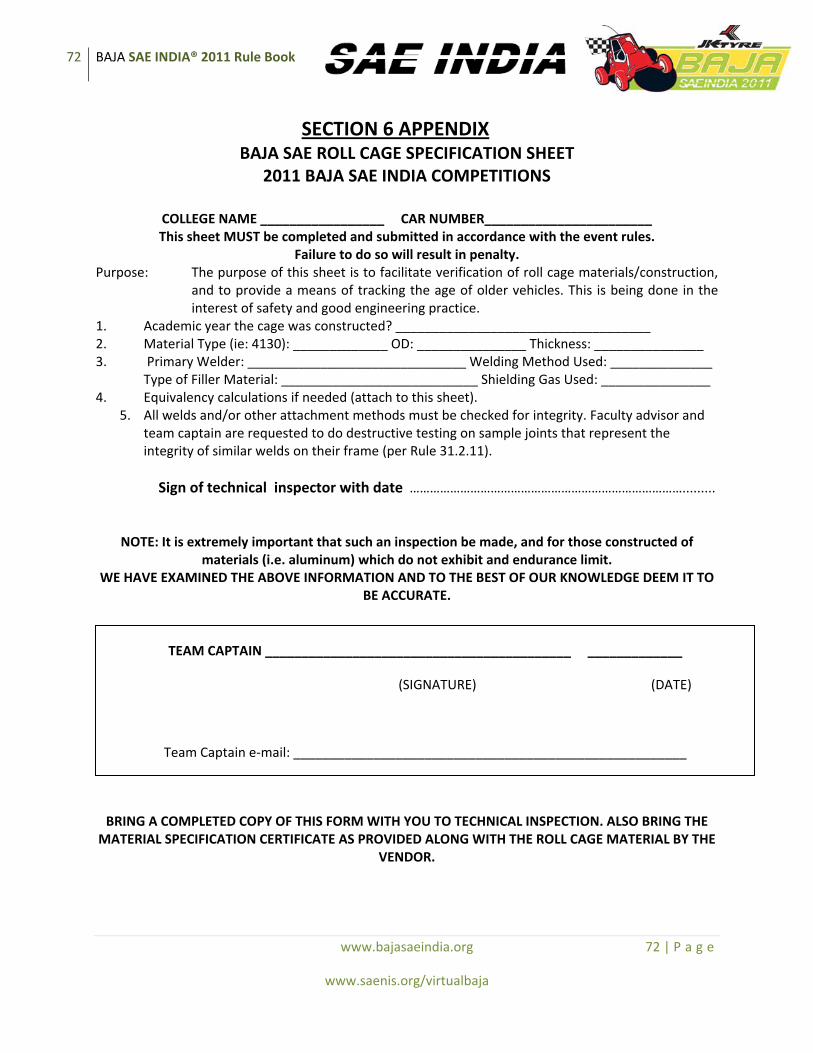
72 BAJA SAE INDIA® 2011 Rule Book
www.bajasaeindia.org 72 | P a g e
www.saenis.org/virtualbaja
SECTION 6 APPENDIX BAJA SAE ROLL CAGE SPECIFICATION SHEET
2011 BAJA SAE INDIA COMPETITIONS
COLLEGE NAME _________________ CAR NUMBER_______________________ This sheet MUST be completed and submitted in accordance with the event rules.
Failure to do so will result in penalty. Purpose: The purpose of this sheet is to facilitate verification of roll cage materials/construction,
and to provide a means of tracking the age of older vehicles. This is being done in the interest of safety and good engineering practice.
1. Academic year the cage was constructed? ___________________________________ 2. Material Type (ie: 4130): _____________ OD: _______________ Thickness: _______________ 3. Primary Welder: ______________________________ Welding Method Used: ______________
Type of Filler Material: ___________________________ Shielding Gas Used: _______________ 4. Equivalency calculations if needed (attach to this sheet).
5. All welds and/or other attachment methods must be checked for integrity. Faculty advisor and team captain are requested to do destructive testing on sample joints that represent the integrity of similar welds on their frame (per Rule 31.2.11).
Sign of technical inspector with date ……………………………………………………………………….........
NOTE: It is extremely important that such an inspection be made, and for those constructed of materials (i.e. aluminum) which do not exhibit and endurance limit.
WE HAVE EXAMINED THE ABOVE INFORMATION AND TO THE BEST OF OUR KNOWLEDGE DEEM IT TO BE ACCURATE.
BRING A COMPLETED COPY OF THIS FORM WITH YOU TO TECHNICAL INSPECTION. ALSO BRING THE MATERIAL SPECIFICATION CERTIFICATE AS PROVIDED ALONG WITH THE ROLL CAGE MATERIAL BY THE
VENDOR.
TEAM CAPTAIN __________________________________________ _____________
(SIGNATURE) (DATE)
Team Captain e‐mail: ______________________________________________________
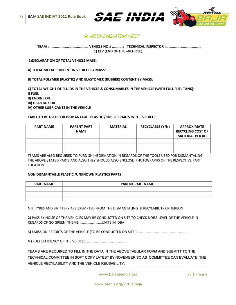
73 BAJA SAE INDIA® 2011 Rule Book
www.bajasaeindia.org 73 | P a g e
www.saenis.org/virtualbaja
GO GREEN EVALUATION SHEET
TEAM : ………………………………….. VEHICLE NO # ………..# TECHNICAL INSPECTOR :……………………………….. 1) ELV (END OF LIFE –VEHICLE)
1)DECLARATION OF TOTAL VEHICLE MASS: A) TOTAL METAL CONTENT IN VEHICLE BY MASS: B) TOTAL POLYMER (PLASTIC) AND ELASTOMER (RUBBER) CONTENT BY MASS: C) TOTAL WEIGHT OF FLUIDS IN THE VEHICLE & CONSUMABLES IN THE VEHICLE (WITH FULL FUEL TANK): I) FUEL II) ENGINE OIL III) GEAR BOX OIL IV) OTHER LUBRICANTS IN THE VEHICLE TABLE TO BE USED FOR DISMANTABLE PLASTIC /RUBBER PARTS IN THE VEHICLE:
PART NAME PARENT PART NAME
MATERIAL RECYCLABLE (Y/N) APPROXIMATE RECYCLING COST OF MATERIAL PER KG
TEAMS ARE ALSO REQUIRED TO FURNISH INFORMATION IN REGARDS OF THE TOOLS USED FOR DISMANTALING THE ABOVE STATED PARTS AND ALSO THEY SHOULD ALSO ENCLOSE PHOTOGRAPHS OF THE RESPECTIVE PART LOCATION. NON DISMANTABLE PLASTIC /UNKNOWN PLASTICS PARTS
PART NAME PARENT PART NAME N.B. TYRES AND BATTTERY ARE EXEMPTED FROM THE DISMANTALING & RECYLABILITY CRITEREON 2) PASS BY NOISE OF THE VEHICLES MAY BE CONDUCTED ON SITE TO CHECK NOISE LEVEL OF THE VEHICLE IN REGARDS OF GO GREEN. THEME …………………….UNITS IN DBA 3) EMISSION REPORTS OF THE VEHICLE (TO BE CONDUCTED ON SITE ) ……………………………………………….. 4 ) FUEL EFFICIENCY OF THE VEHICLE :……………………………………. TEAMS ARE REQUIRED TO FILL IN THE DATA IN THE ABOVE TABULAR FORM AND SUBMITT TO THE TECHNICAL COMMITTEE IN SOFT COPY LATEST BY NOVEMBER SO AS COMMITTEE CAN EVALUATE THE VEHICLE RECYLABILITY AND THE VEHICLE REUSABILITY.
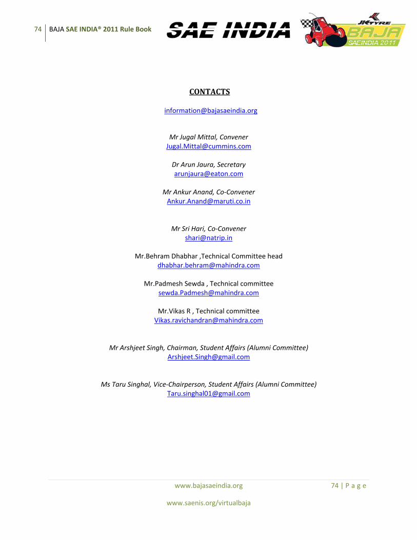
74 BAJA SAE INDIA® 2011 Rule Book
www.bajasaeindia.org 74 | P a g e
www.saenis.org/virtualbaja
CONTACTS
Mr Jugal Mittal, Convener [email protected]
Dr Arun Jaura, Secretary [email protected]
Mr Ankur Anand, Co‐Convener [email protected]
Mr Sri Hari, Co‐Convener [email protected]
Mr.Behram Dhabhar ,Technical Committee head
Mr.Padmesh Sewda , Technical committee [email protected]
Mr.Vikas R , Technical committee [email protected]
Mr Arshjeet Singh, Chairman, Student Affairs (Alumni Committee) [email protected]
Ms Taru Singhal, Vice‐Chairperson, Student Affairs (Alumni Committee) [email protected]

75 BAJA SAE INDIA® 2011 Rule Book
www.bajasaeindia.org 75 | P a g e
www.saenis.org/virtualbaja
Note: Please direct all queries to Alumni Committee Member
ANNEXURE
RECOMMENDATIONS OF CODE OF CONDUCT DURING BAJA SAEINDIA 2011 EVENT
• If a technical inspector at site finds the vehicle incomplete during his/her final technical level vehicle inspection, the team is likely to attract penalty / rejection as deemed fit by the organizers.
• Any team performing any welding operation at site should do it in a defined area preferably with empty fuel tanks.
• Teams which do not pass inspection at the 1st inspection may be penalized as deemed fit by the organizers.
• No one else will be permitted other than team members to work on vehicle if found so, the complete team may be penalized as deemed fit by the organizers, which may include disqualification.
• Team members without authentic ID Cards will be liable for penalty as deemed fit by the organizers.
• Event timings shall be strictly adhered to, including that the organizers reserving the right to refuse re-inspection.
• Team may file a protest against professionally made vehicles with supporting evidence. The decision of the organizers in this regard will be final and binding on all parties.
76 BAJA SAE INDIA® 2011 Rule Book
www.bajasaeindia.org 76 | P a g e
www.saenis.org/virtualbaja
Virtual BAJA SAEINDIA 20110
Event details and guidelines
77 BAJA SAE INDIA® 2011 Rule Book
www.bajasaeindia.org 77 | P a g e
www.saenis.org/virtualbaja
Competition Rules and Procedures
4.1 About
The BAJA SAE INDIA Virtual Design Challenge is an‐inter collegiate competition for undergraduate engineering students. The competition aims at exposing the engineering students to real world problems based on the fields of Computer Aided Engineering and Simulation of products. The students are encouraged to design, analyze and simulate a product for a fictitious firm outsourcing its product development to the students. The event is organized by Society of Automotive Engineers USA’s Indian Chapter, SAE‐INDIA. The event comprises of judging students on their creativity, innovations, designing capabilities and knowledge of the problem statement and its related subjects. The aim is to motivate students to take up challenging and research oriented projects in the fields of automotive industry, through the application of computer aided design softwares and simulation and finite element analysis packages.
4.2 Objectives
Every team shall design, analyze and simulate a virtual prototype of a BAJA vehicle for a fictitious firm to manufacture the product at a rate of 4000 vehicles per year. The students shall design the vehicles with their knowledge of the fields of engineering using standard designing and simulation packages. They are required to keep in mind that the product is to be designed for assembly, thus, the approach of the project include principles for Design For Assembly. The students are required to submit the following reports: Engineering Design Report: giving description of the vehicle assembly and its aggregates.
The teams are required to design each component as used in BAJA Vehicles and give a detailed description of each. The components designed are thus to be assembled in the form of a functional BAJA Vehicle which could thus be manufactured on a fictitious assembly line. All the teams shall give an operation sequence of assembly that would result in production of a sound BAJA vehicle. The teams would also be required to analyze the integrity of their BAJA vehicles using sound practices of CAE and simulate their vehicles using simulation packages. The teams would be required to give a fifteen minute presentation to the manufacturer, about their design and its advantages to the customers as well as the producer.
78 BAJA SAE INDIA® 2011 Rule Book
www.bajasaeindia.org 78 | P a g e
www.saenis.org/virtualbaja
4.3 Rules
The Problem Statement
Every team is required to design, analyze and simulate a virtual prototype of a BAJA vehicle for manufacturing by a fictitious firm at the rate of 4000 units per year.
The prototype should be designed with sound practices of engineering, analyzed for safety and simulated for dynamic performance using standard computer aided designing, analysis and simulation packages available. The participating teams must function as a design team, dealing into designing of various components of the vehicle. The design must include the assembly of all the components required to make a pleasing and satisfying BAJA vehicle e.g, powertrain sub assemblies, steering, braking, wheel assemblies, vehicle ergonomics and aesthetics etc. A suitable explanation of the design of all the components is to be given in the form of a report to the manufacturer along with a brief presentation dealing with the relative advantages of the design, its feasibility etc.
The vehicle must satisfy all the rules concerning safety, roll cage integrity and minimum roll cage specifications as specified in the BAJA SAEINDIA 2011 Rulebook and BAJA SAEINDIA Virtual Design Challenge 2010.
The teams may go to any extent as possible and provide as much detailing in design as is realistic to them. The teams would be required to submit a design report of their vehicle. The report shall be of 14 pages in total, printed back to back. The teams would also be required to present their designs before the judging panel. The presentation should be of 20 slides and 15 minutes maximum. The teams must adhere to the guidelines as mentioned above, else, penalty points may be awarded as per the prudence of the panel. The teams are encouraged to present their case on the following parameters: FEA: description of the finite element study carried out of the aggregates and the complete vehicle Design Optimization: description of the optimization and changes brought into the design on the basis of suitable conceptualizations and on analysis of FEA results
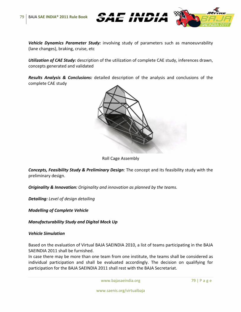
79 BAJA SAE INDIA® 2011 Rule Book
www.bajasaeindia.org 79 | P a g e
www.saenis.org/virtualbaja
Vehicle Dynamics Parameter Study: involving study of parameters such as manoeuvrability (lane changes), braking, cruise, etc Utilization of CAE Study: description of the utilization of complete CAE study, inferences drawn, concepts generated and validated Results Analysis & Conclusions: detailed description of the analysis and conclusions of the complete CAE study
Roll Cage Assembly Concepts, Feasibility Study & Preliminary Design: The concept and its feasibility study with the preliminary design. Originality & Innovation: Originality and innovation as planned by the teams. Detailing: Level of design detailing Modelling of Complete Vehicle Manufacturability Study and Digital Mock Up Vehicle Simulation Based on the evaluation of Virtual BAJA SAEINDIA 2010, a list of teams participating in the BAJA SAEINDIA 2011 shall be furnished. In case there may be more than one team from one institute, the teams shall be considered as individual participation and shall be evaluated accordingly. The decision on qualifying for participation for the BAJA SAEINDIA 2011 shall rest with the BAJA Secretariat.

80 BAJA SAE INDIA® 2011 Rule Book
www.bajasaeindia.org 80 | P a g e
www.saenis.org/virtualbaja
The decision of the BAJA Secretariat / BAJA Organizing Committee / Virtual BAJA Committee shall be final and binding.

81 BAJA SAE INDIA® 2011 Rule Book
www.bajasaeindia.org 81 | P a g e
www.saenis.org/virtualbaja
Contacts
Mr Deepak Sawkar Convener, Virtual BAJA SAEINDIA 2011
Mr Ankur Anand Co‐Convener, BAJA SAEINDIA 2011 & Coordinator, Virtual BAJA SAEINDIA 20110