Backup of 80setmanualTUT
35
HELLO.
Transcript of Backup of 80setmanualTUT

H E L L O .
To begin pick out and unfold the worksheet
Circuits components and wires are most visible on the black side.Light experiments are best done on the white side

Electrical Circuits
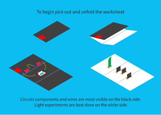
Making Connections
Connections are made easily using the attachments on your connecting wires. Connecting wires come in male and female wires
male
female
Connecting two wires Connecting to othercomponents
All connections are made by gently pushing the cable into the leads on the component that you want to connect to
3
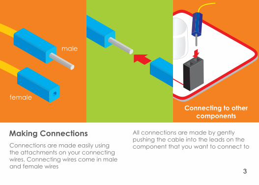
To make connection to your battery, press the negative (flat) end of the battery against the spring and push down until the battery fits snugnly inside the battery case as shown below.
battery holder
Assemble Your First Circuit
You have to take note of the + and - signs indicated on the batteries. They show the direction of flow of current
4
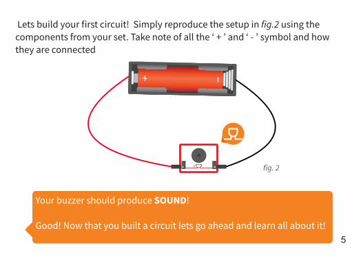
Lets build your first circuit! Simply reproduce the setup in fig.2 using the components from your set. Take note of all the ‘ + ’ and ‘ - ’ symbol and how they are connected
+
Your buzzer should produce SOUND!
Good! Now that you built a circuit lets go ahead and learn all about it!
fig. 2
5
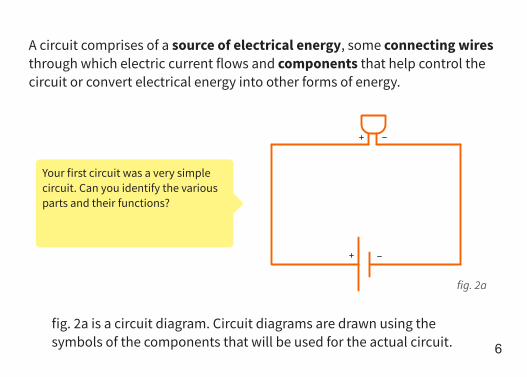
A circuit comprises of a source of electrical energy, some connecting wires through which electric current flows and components that help control the circuit or convert electrical energy into other forms of energy.
Your first circuit was a very simple circuit. Can you identify the various parts and their functions?
fig. 2a
fig. 2a is a circuit diagram. Circuit diagrams are drawn using the symbols of the components that will be used for the actual circuit.
6
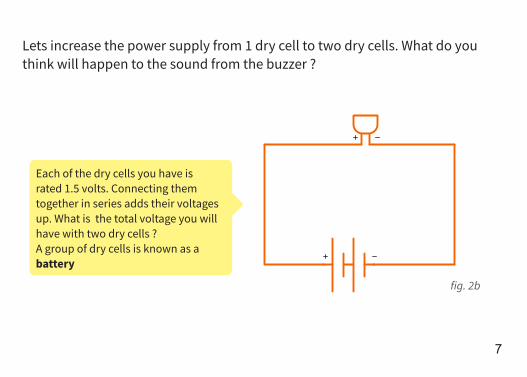
Lets increase the power supply from 1 dry cell to two dry cells. What do you think will happen to the sound from the buzzer ?
Each of the dry cells you have is rated 1.5 volts. Connecting them together in series adds their voltages up. What is the total voltage you will have with two dry cells ? A group of dry cells is known as a battery
fig. 2b
7

Refer to the fig.2b. Connect two(2) battery holders together. Connect the battery to a buzzer using your connecting wires as shown below.
+
Your buzzer will produce a SOUND! loud
We still have to disconnect some wires to open our circuit. How can we turn off our circuit without disconnecting our wires? 8
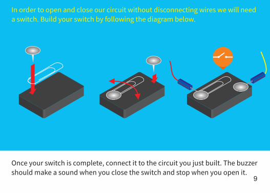
In order to open and close our circuit without disconnecting wires we will need a switch. Build your switch by following the diagram below.
Once your switch is complete, connect it to the circuit you just built. The buzzer should make a sound when you close the switch and stop when you open it.
9
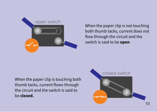
closed switch
open switchWhen the paper clip is not touching both thumb tacks, current does not flow through the circuit and the switch is said to be open
When the paper clip is touching both thumb tacks, current flows through the circuit and the switch is said to be closed.
10

Apart from a switch, there are components that allow current to flow depending on how you connect them. A diode allows current to flow in only one direction.
A diode connected such that current flow through it is said to be forward biased else is said to be reversed biased.Build the circuit above, ensure the diode is forward biased as shown in the diagram and close the switch. The buzzer should sound. Reverse the diode several times and observe.
Diodes
+fig. 4
11

LED (Light Emitting Diode)There is a special kind of diode that emits light when connected in forward bias. Its know as LED(Light Emitting Diode). There are different LEDs in your set.
Use your set to build the circuit described in figure 5a. It consists of a battery with two(2) dry cells, an LED and a 33 If you Ω resistor (which we will look at next).set up your connections correctly, the LED should light up!
33 Ω
fig. 5
fig. 5a
12
33Ω
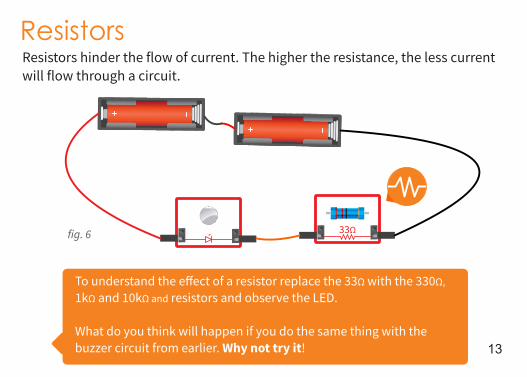
ResistorsResistors hinder the flow of current. The higher the resistance, the less current will flow through a circuit.
To understand the effect of a resistor replace the 33Ω with the 330Ω, 1kΩ and 10kΩ and resistors and observe the LED.
What do you think will happen if you do the same thing with the buzzer circuit from earlier. Why not try it!
fig. 6
13
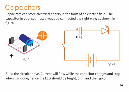
CapacitorsCapacitors can store electrical energy in the form of an electric field. The capacitor in your set must always be connected the right way; as shown in fig.7a.
100 Fµ
Build the circuit above. Current will flow while the capacitor charges and stop when it is done, hence the LED should be bright, dim, and then go off.
+
fig. 7
fig. 7a
14
+

100µF
Next, we will build a circuit that allows us to charge and discharge a capacitor .
+
15

Capacitors charging and discharging circuit
To build our charge-discharge circuit as shown in fig.7a, we will require a two-way switch. Lets modify our previous switch to create the special switch shown below.
16
100µ
F
33Ω
17
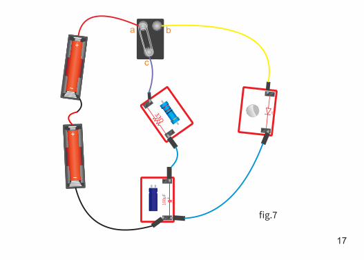
+
fig.7
a b
c

100 Fµ
+
fig. 7b
100 Fµ
+
fig. 7a
a
c
b a b
c
18
Once you have finished building the circuit, close the switch so that the paper clipmakes contact with thumb tack “a” and “c” as shown in figure 7a. Once you do this,the capacitor will start charging. Wait for a few seconds to allow the capacitor to charge and then close the switch so that the thumb tack makes contact between thumb tack “b” and “c”. The led will turn on and go off slowly.
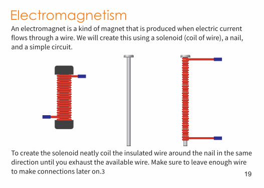
ElectromagnetismAn electromagnet is a kind of magnet that is produced when electric current flows through a wire. We will create this using a solenoid (coil of wire), a nail, and a simple circuit.
To create the solenoid neatly coil the insulated wire around the nail in the same direction until you exhaust the available wire. Make sure to leave enough wire to make connections later on.3 19
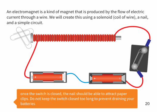
An electromagnet is a kind of magnet that is produced by the flow of electric current through a wire. We will create this using a solenoid (coil of wire), a nail, and a simple circuit.
once the switch is closed, the nail should be able to attract paper clips. Do not keep the switch closed too long to prevent draining your batteries 20

Magnetic FieldThere is a defined area around our electromagnet where the force is felt the strongest. This area is called the magnetic field.
To make a visible magnetic field we will need more current. We need six(6) 1.5 volts dry cells or one 9 volts battery which should be available in your local store. Join with your classmates because it requires at least 4 science sets
Be careful, the electromagnet gets quite warm
21

On the white side of your worksheet sprinkle some iron fillings evenly and place your electromagnet in the center of the iron fillings. Gently tap the worksheet until the iron fillings draw the magnetic field! 22

Light
23

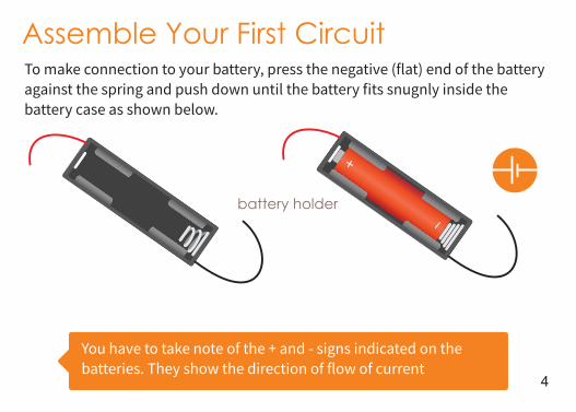
The contraptions in the science set for “Light” experiments require setup with triangle stands as shown below
These are the component we will use for our light source
33Ω24
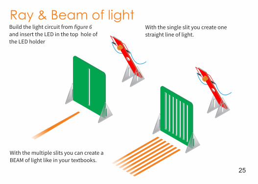
Build the light circuit from figure 6 and insert the LED in the top hole of the LED holder
With the multiple slits you can create a BEAM of light like in your textbooks.
Ray & Beam of lightWith the single slit you create one straight line of light.
25
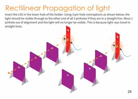
Rectilinear Propagation of lightInsert the LED in the lower hole of the holder. Using 3 pin-hole contraptions as shown below, the light should be visible through to the other end of all 3 pinholes if they are in a straight line. Move 1 pinhole out of alignment and the light will no longer be visible. This is because light rays travel in straight lines.
26
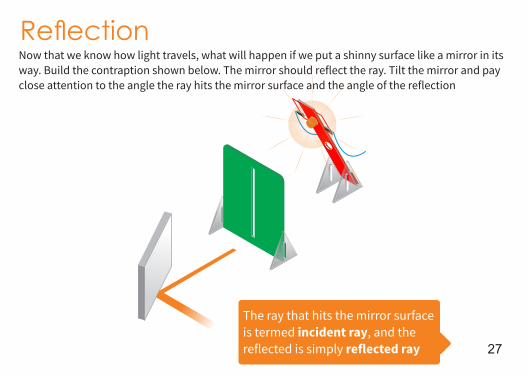
ReectionNow that we know how light travels, what will happen if we put a shinny surface like a mirror in its way. Build the contraption shown below. The mirror should reflect the ray. Tilt the mirror and pay close attention to the angle the ray hits the mirror surface and the angle of the reflection
The ray that hits the mirror surface is termed incident ray, and the reflected is simply reflected ray 27
a b
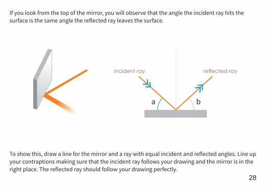
If you look from the top of the mirror, you will observe that the angle the incident ray hits the surface is the same angle the reflected ray leaves the surface.
To show this, draw a line for the mirror and a ray with equal incident and reflected angles. Line up your contraptions making sure that the incident ray follows your drawing and the mirror is in the right place. The reflected ray should follow your drawing perfectly.
incident ray reected ray
28

LDR (Light Dependent Resistor)The LDR is the first interactive component you get to work with under basic electronics. It is a resistor, but its resistance is proportional to the intensity of light that shines on it.
Build the circuit above(figure 10a). When you cover the LDR with your finger the LED should dim slightly. To amplify the effect, we will use a component called a transistor, next.
fig. 10
fig. 10a
29
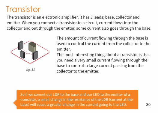
TransistorThe transistor is an electronic amplifier. It has 3 leads; base, collector and emitter. When you connect a transistor to a circuit, current flows into the collector and out through the emitter, some current also goes through the base.
The amount of current flowing through the base is used to control the current from the collector to the emitter.The most interesting thing about a transistor is that you need a very small current flowing through the base to control a large current passing from the collector to the emitter.
So if we connet our LDR to the base and our LED to the emitter of a transistor, a small change in the resistance of the LDR (current at the base) will cause a greater change in the current going to the LED.
fig. 11
30
Light Detector Dark Detector
33Ω
10kΩ 10kΩ
33Ω
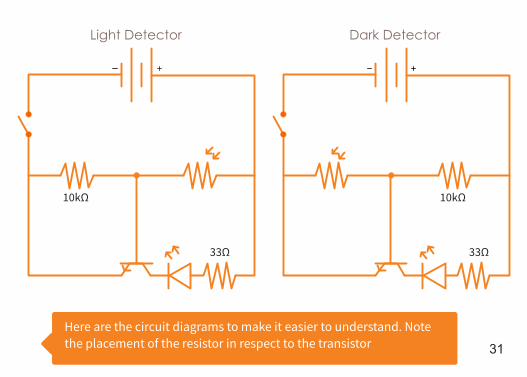
Here are the circuit diagrams to make it easier to understand. Note the placement of the resistor in respect to the transistor 31
33Ω
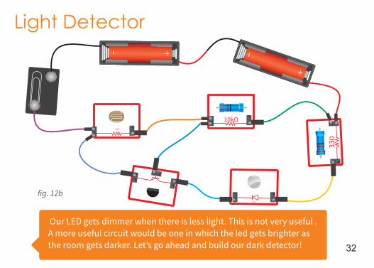
Light Detector
Our LED gets dimmer when there is less light. This is not very useful . A more useful circuit would be one in which the led gets brighter as the room gets darker. Let’s go ahead and build our dark detector!
10kΩ
fig. 12b
32

Dark Detector
If you circuit works, congratulations! You have just created an automatic light system. When it gets dark, your smart circuit will turn on the light automatically!
10kΩ
33Ω
fig. 12c
33

C O N G R A T SExperiment more and continue to live the awesome life of a scientist !
Experiment more and continue to live the awesome life of a scientist !