Background Hurricane Katrina - Missouri S&Tweb.mst.edu/~rogersda/AEG-2008-New...
84
GEOLOGIC INFLUENCE ON FLOOD CONTROL INFRASTRUCTURE DURING HURRICANE KATRINA J. David Rogers, Ph.D., P.E., P.G. Karl F. Hasselmann Chair in Geological Engineering Missouri University of Science & Technology for the Colorado School of Mines Golden, Colorado October 6, 2011
Transcript of Background Hurricane Katrina - Missouri S&Tweb.mst.edu/~rogersda/AEG-2008-New...

GEOLOGIC INFLUENCE ON FLOOD CONTROL
INFRASTRUCTURE DURING HURRICANE KATRINA
J. David Rogers, Ph.D., P.E., P.G. Karl F. Hasselmann Chair in Geological Engineering
Missouri University of Science & Technology
for the
Colorado School of Mines Golden, Colorado
October 6, 2011

Where you build in a river
delta influences future performance
Firm Sand and Gravel
versus
Soft and Mushy
Backswamp Foundations
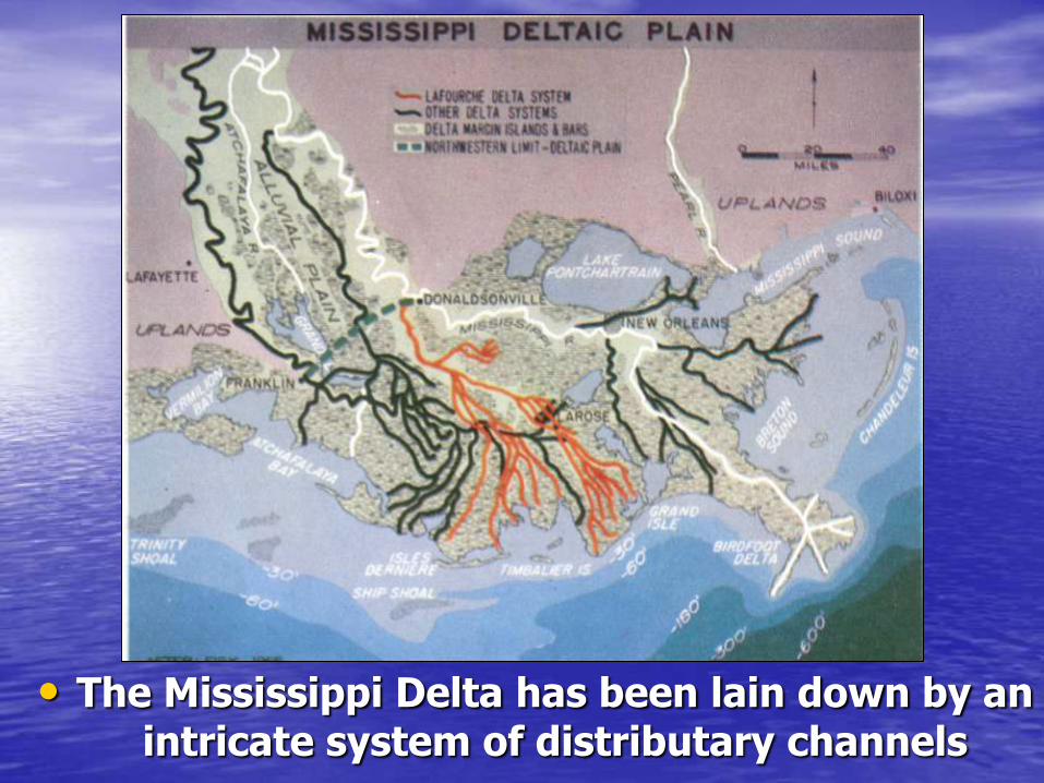
• The Mississippi Delta has been lain down by an intricate system of distributary channels

• Typical cross section through the sandy bank levees of the Mississippi River, illustrating how the river’s main channel lies above the surrounding flood plain, which were poorly drained swamp lands prior to reclamation.
• There is significant hydraulic sorting of materials deposited on either side of these levees, as sketched below.

Some of the most
treacherous and complex
foundation conditions exist
in deltas -
Site characterization
requires considerable
expertise and flexible
budgets
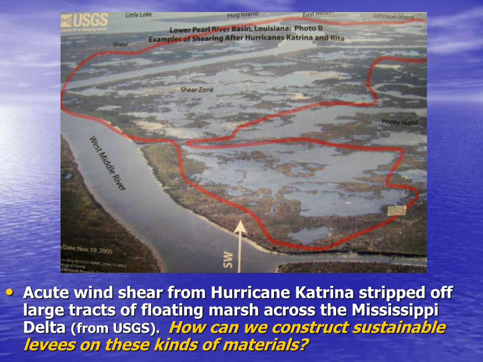
• Acute wind shear from Hurricane Katrina stripped off large tracts of floating marsh across the Mississippi Delta (from USGS). How can we construct sustainable levees on these kinds of materials?

• “Land loss” in Breton Sound (shown in light blue) after Hurricanes Katrina and Rita in 2005 (from USGS-NWRC).

Discontinuous nature of stratigraphy in Mississippi Delta
• The stem channels of the Mississippi and its distributaries leave thick sequences of point bar sands adjacent to the river; then historic marshes (lowland backswamp), distributary ridges, and backswamps, like those on the margins of large shallow bodies of water, like Lake Borgne and Lake Pontchartrain.

• Block diagram illustrating relationships between subaerial and subaqueous deltaic environments in relation to a single distributary lobe.
• Note fresh water cypress and gum swamps, peat, and interdistributary sediments.

• Typical geologic cross section - through New Orleans Inner
Harbor Navigation Channel
• Note how conditions vary on either side of the channel
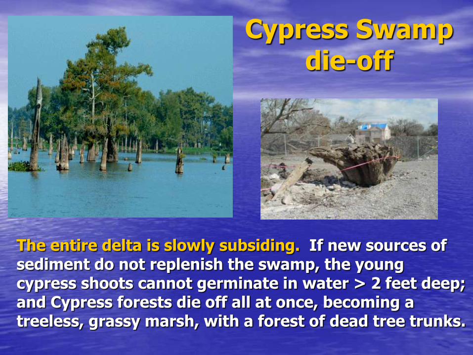
Cypress Swamp die-off
The entire delta is slowly subsiding. If new sources of sediment do not replenish the swamp, the young cypress shoots cannot germinate in water > 2 feet deep; and Cypress forests die off all at once, becoming a treeless, grassy marsh, with a forest of dead tree trunks.
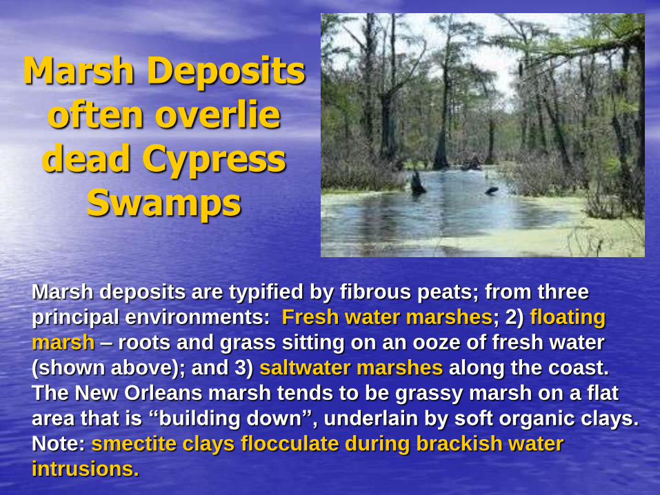
Marsh Deposits often overlie dead Cypress
Swamps
Marsh deposits are typified by fibrous peats; from three
principal environments: Fresh water marshes; 2) floating
marsh – roots and grass sitting on an ooze of fresh water
(shown above); and 3) saltwater marshes along the coast.
The New Orleans marsh tends to be grassy marsh on a flat
area that is “building down”, underlain by soft organic clays.
Note: smectite clays flocculate during brackish water
intrusions.
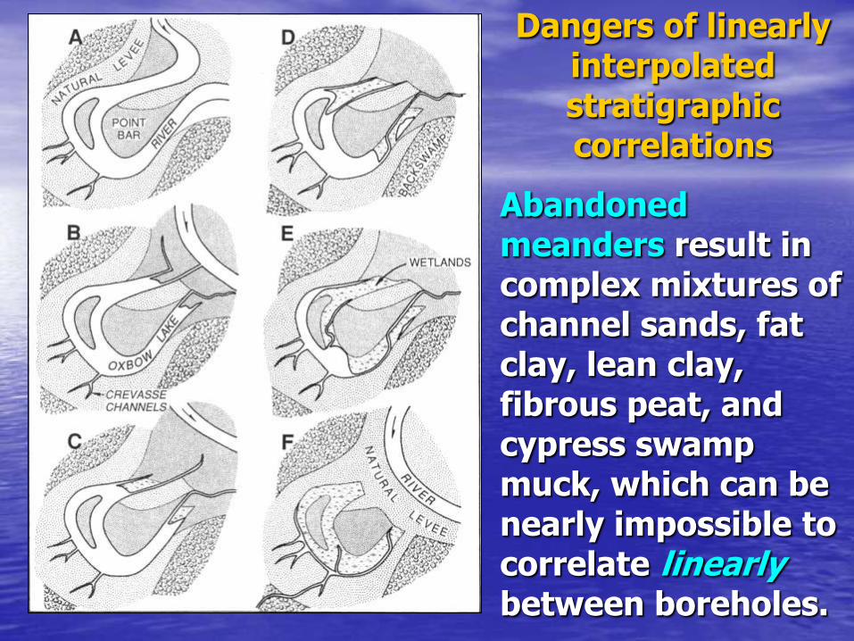
Abandoned meanders result in complex mixtures of channel sands, fat clay, lean clay, fibrous peat, and cypress swamp muck, which can be nearly impossible to correlate linearly between boreholes.
Dangers of linearly interpolated stratigraphic correlations

Clay drapes and pockets
Example showing complex depositional relationships between units in a distibutary meander belt. Note discontinuous nature (from Saucier, 1994).

Depositional Environment Keys developed by the Corps of
Engineers during the late 1950s
• Cypress wood = fresh water swamp
• Fibrous peaty mtls = marshes
• Fat Clays with organics; usually lacustrine. A pure fat clay has high w/c and consistency of peanut butter
• Interdistributary clays; paludal environments; lakes. Silt lenses when water shallow and wind swept waves
• Lean clays CL LL<50, silty and w/c <60%
• Fat clays CH LL>50 no silt and w/c >70%

Geotechnical Problems
Characterizing Levee Foundations

• Backswamp swales are subject to sieving of fines by occasional higher velocity runoff
• This causes hydraulic conductivity to increase along the sinuous runoff path, as opposed to other seepage paths, within the plane of sedimentation
most pervious

• The porous and highly conductive nature of the backswamp deposits was revealed during post-Katrina drilling and sampling operations.
• Highly conductive in horizontal plane
Water squirted up adjacent boreholes when advancing Shelby tubes
Drill rig advancing Shelby tubes in backswamp deposits

Anisotropy of backswamp deposits
• Sudden die-off of organics creates highly anisotropic fabric; preferentially layered

Note infilled meander channel
Geologic section along middle reach of the 17th St. Canal. Note filled meander channel over 50 feet deep.

io= 0.8
Pervious foundation materials most at risk - London Avenue Canal (South Breach)
Very little reliable data exists on horizontal hydraulic
conductivity of foundation soils in the Mississippi Delta

Undrained shear strength vs depth at the East IHNC North Breach
Blue lines shows profile of CPT-1, with NGI tip corrections for the three units encountered
Green line shows strength profile selected by the NSF team
Red lines shows the strength distribution at the toe of the levee calculated by Duncan and Brandon at VPI using an undrained strength ratio of 0.27 and vertical geostatic stresses
Which soil shear strength should we
use?

• Impact of dead load, or the Su versus p’ factor. The strength of clayey soils increases with increasing confinement created by placement of the earthen dike on natural soils.
• Soil is always strongest beneath centerline of levee, where most boreholes get drilled; but weakest beneath flanks. Also, significant dry vs wet side factors.
Strongest soils
Weakest soils
Below sea level, so always saturated
Dry during drought
Water side Land side of levee

17th Street Canal: Soft Gray Clay (CH) Desiccation Horizons Beneath Levee Toe
Group 2 (Toe, outside breach south with CPT data)
-40
-35
-30
-25
-20
-15
-10
-5
0
0 0.1 0.2 0.3 0.4 0.5 0.6 0.7 0.8 0.9 1
Su/s'vo
CPT-2
Group 2 (Toe, outside breach south with CPT data)
-40
-35
-30
-25
-20
-15
-10
-5
0
1 2 3 4 5
OCRE
lev
ati
on
(ft
)
CPT-2 PLAXIS (Soft Soil Model
prediction)
(su/s'v)NC ~ 0.31
(Nk = 12)
Tra
nsitio
n &
Gre
y C
lay (C
H)
Desiccation horizons always stronger

Common Levee Failure
Mechanisms

Levee construction techniques for the MR&T in 1930s
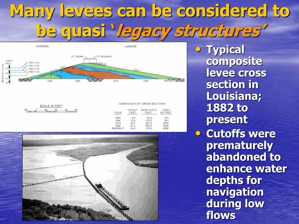
Many levees can be considered to be quasi ‘legacy structures’
• Typical composite levee cross section in Louisiana; 1882 to present
• Cutoffs were prematurely abandoned to enhance water depths for navigation during low flows
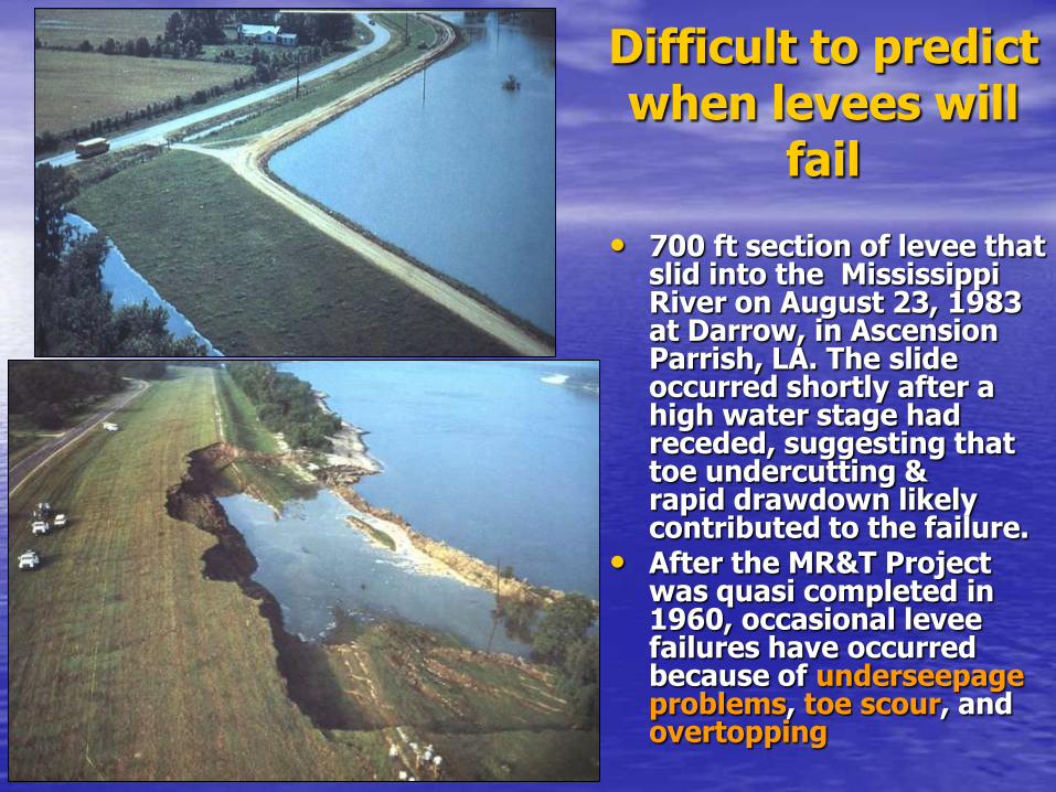
Difficult to predict when levees will
fail
• 700 ft section of levee that slid into the Mississippi River on August 23, 1983 at Darrow, in Ascension Parrish, LA. The slide occurred shortly after a high water stage had receded, suggesting that toe undercutting & rapid drawdown likely contributed to the failure.
• After the MR&T Project was quasi completed in 1960, occasional levee failures have occurred because of underseepage problems, toe scour, and overtopping
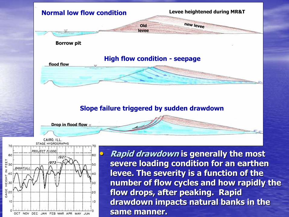
• Rapid drawdown is generally the most severe loading condition for an earthen levee. The severity is a function of the number of flow cycles and how rapidly the flow drops, after peaking. Rapid drawdown impacts natural banks in the same manner.
Normal low flow condition
Slope failure triggered by sudden drawdown
Levee heightened during MR&T
Borrow pit
Old levee
High flow condition - seepage flood flow
Drop in flood flow
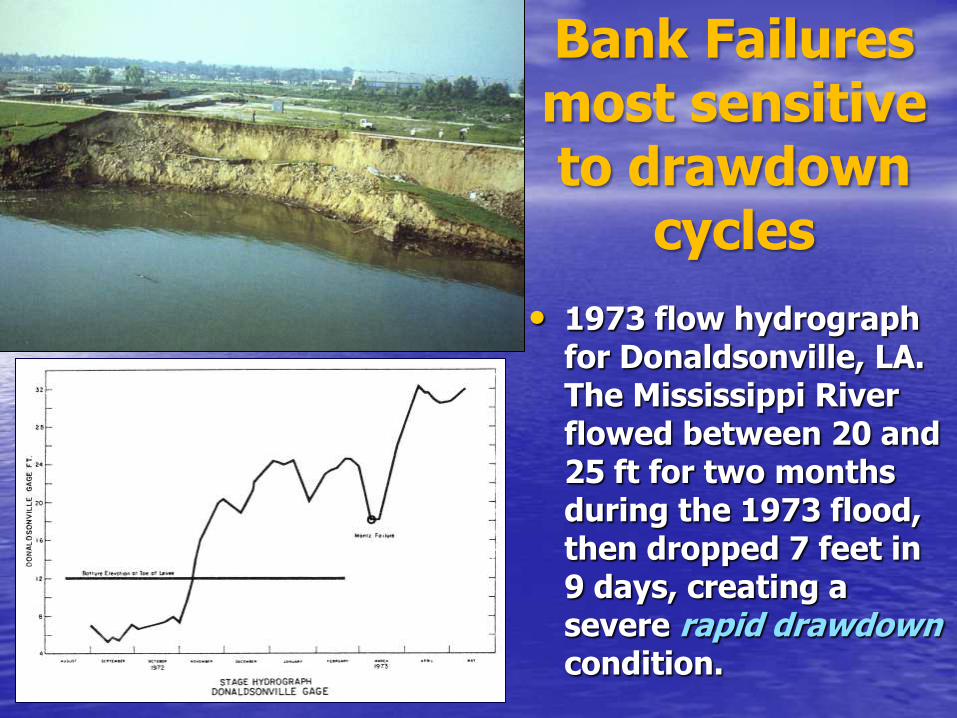
• 1973 flow hydrograph for Donaldsonville, LA. The Mississippi River flowed between 20 and 25 ft for two months during the 1973 flood, then dropped 7 feet in 9 days, creating a severe rapid drawdown condition.
Bank Failures most sensitive to drawdown
cycles

Asymmetric channels
• The Mississippi channel is sinuous; migrating towards the outside of downstream bends through bank undercutting. Levees had to set back from these bends.
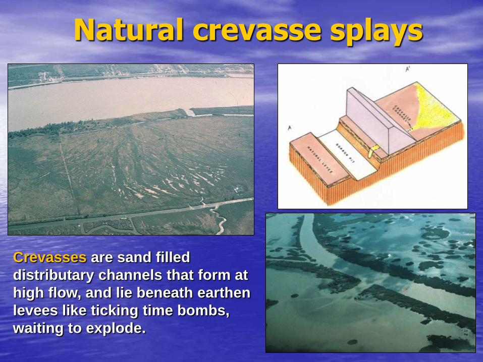
Natural crevasse splays
Crevasses are sand filled
distributary channels that form at
high flow, and lie beneath earthen
levees like ticking time bombs,
waiting to explode.

Hahnville is just upstream
of New Orleans
• Note classic birdfoot pattern of sand-filled distributary channels, shown in yellow
• Note development

Seepage crevasse exposed at the east levee of the IHNC breach after Hurricanes Katrina and Rita

Io: 0.8Io: 1.0 Io: 0.8Io: 1.0
• Hydraulic gradients for the south breach on IHNC east bank; storm surge at 14.4ft (MSL). Maximum exit gradient at the levee toe is io ≈ 0.8 to 1.0, at threshold for hydraulic piping.
• This may help to explain the persistent wet spot noted on the backfill of the Jourdan Avenue conduit backfill for weeks afterward.
Hydraulic gradients for piping and uplift
Same location as runoff induced erosion, on inboard toe
(no gap yet)
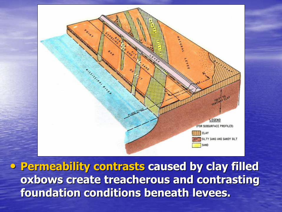
• Permeability contrasts caused by clay filled oxbows create treacherous and contrasting foundation conditions beneath levees.
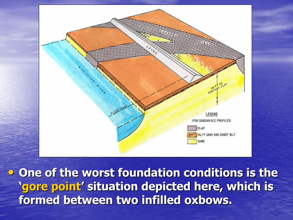
• One of the worst foundation conditions is the ‘gore point’ situation depicted here, which is formed between two infilled oxbows.

• Clay filled oxbows consolidate under the load imposed by the earthen levees, causing these levees to settle and sink.
• Differential settlement is a major obstacle in maintaining levees.

Shallow Seepage through pervious
subsoils can hasten levee failure

Deflected flood wall along the London Avenue Drainage Canal in New Orleans. This failure was driven by excessive transient pore pressures developed in the underlying Pine Island Sands.

Photo by Ivor van Heerden
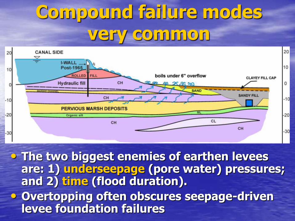
Compound failure modes very common
• The two biggest enemies of earthen levees are: 1) underseepage (pore water) pressures; and 2) time (flood duration).
• Overtopping often obscures seepage-driven levee foundation failures
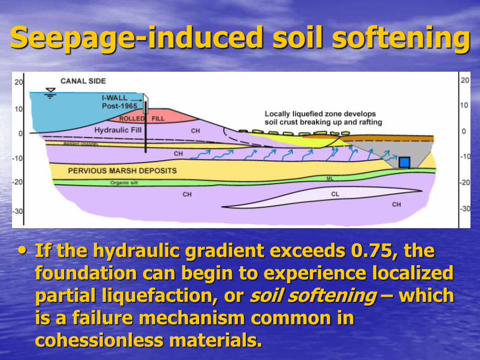
Seepage-induced soil softening
• If the hydraulic gradient exceeds 0.75, the foundation can begin to experience localized partial liquefaction, or soil softening – which is a failure mechanism common in cohessionless materials.

… followed by Local Bearing Capacity Failure
• The loss of soil shear strength in the levee’s land side toe area can trigger a massive slope failure on the outboard side of the levee.
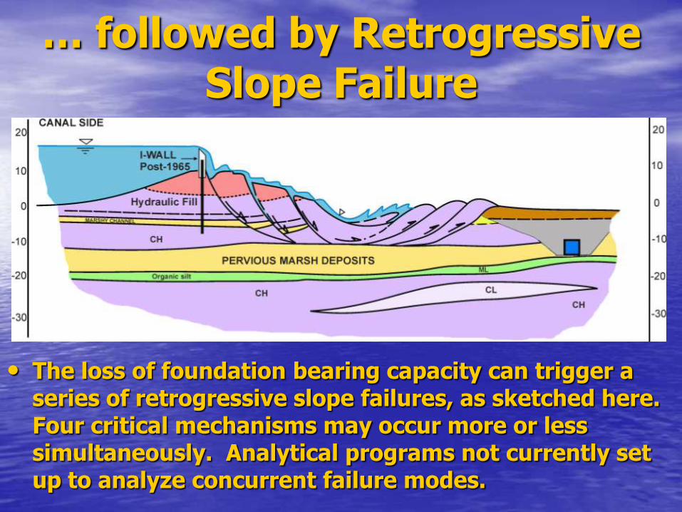
… followed by Retrogressive Slope Failure
• The loss of foundation bearing capacity can trigger a series of retrogressive slope failures, as sketched here. Four critical mechanisms may occur more or less simultaneously. Analytical programs not currently set up to analyze concurrent failure modes.

Overtopping Failures….
appear easy to understand
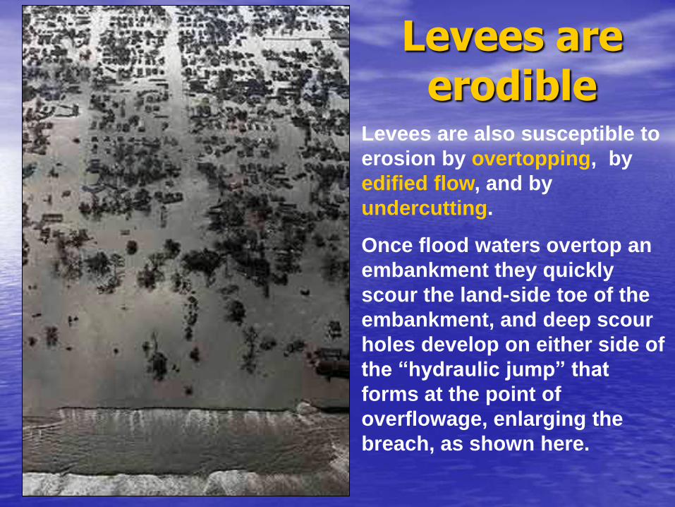
Levees are erodible
Levees are also susceptible to
erosion by overtopping, by
edified flow, and by
undercutting.
Once flood waters overtop an
embankment they quickly
scour the land-side toe of the
embankment, and deep scour
holes develop on either side of
the “hydraulic jump” that
forms at the point of
overflowage, enlarging the
breach, as shown here.

Back-Slope
Critical Erosion
Scalloping
Notching
Through-Flow
Erosion
Two kinds of overtopping-induced damage
Velocity-induced scour at toe of back slope, at flow transition.
Accelerates when vegetation stripped off, depending on cohesion of
embankment materials
Scalloping and notching on the fetch side of the levee, due to wave
pounding; and piping fomented by emergent seepage at the toe of the
back slope
Note: damage at back slope toe looks similar for both modes
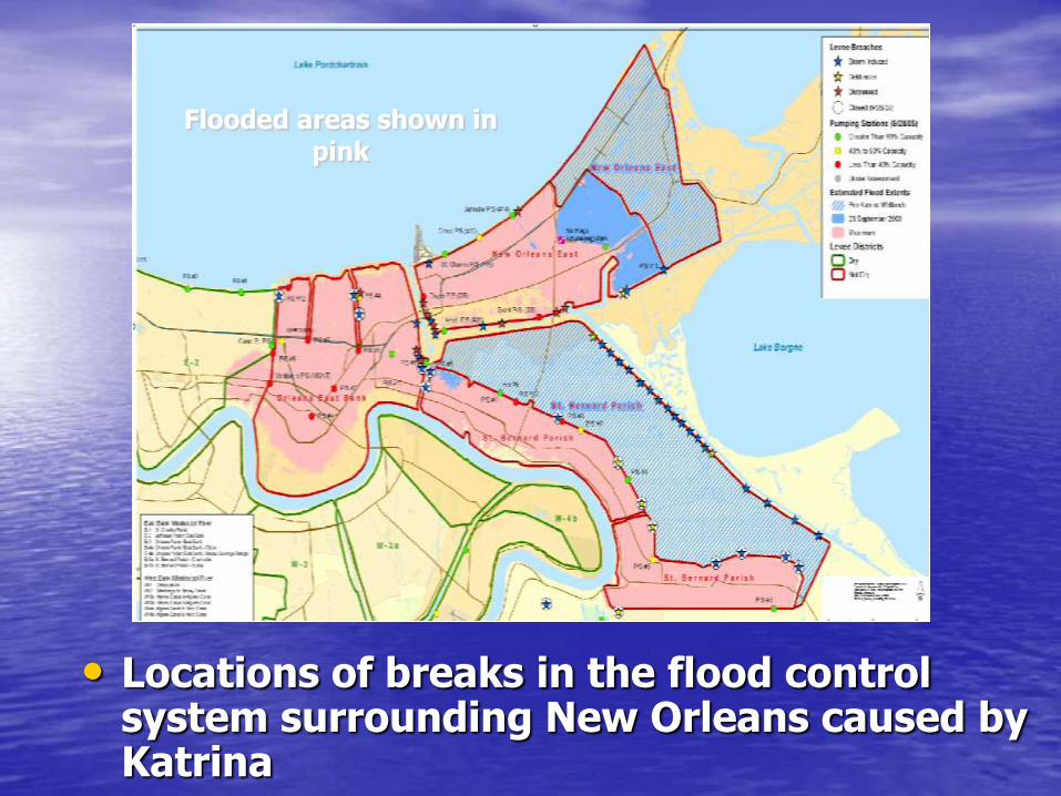
• Locations of breaks in the flood control system surrounding New Orleans caused by Katrina
Flooded areas shown in pink
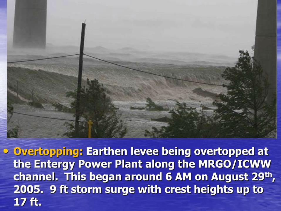
• Overtopping: Earthen levee being overtopped at the Entergy Power Plant along the MRGO/ICWW channel. This began around 6 AM on August 29th, 2005. 9 ft storm surge with crest heights up to 17 ft.

• Resilient structures: The levee protecting the Entergy Power Plant beneath the Route 47/Interstate 310 viaduct over the MRGO/ICWW channel at Michoud survived 8+ hours of overtopping with only moderate erosion.

• Good performance: some portions of the Mississippi River Gulf Outlet (MRGO) Channel survived waves as high as 17 feet, triggered by a 9+ foot storm surge off Lake Borgne (to the right)

• Survivable levees: The storm surge pushed houses up on top of some levees, leaving them scattered about …
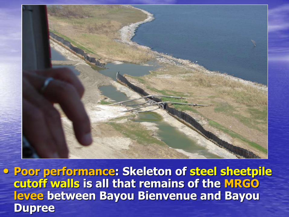
• Poor performance: Skeleton of steel sheetpile cutoff walls is all that remains of the MRGO levee between Bayou Bienvenue and Bayou Dupree

• Poor performance: MRGO levee completely washed away, about two miles southeast of Bayou Dupree.
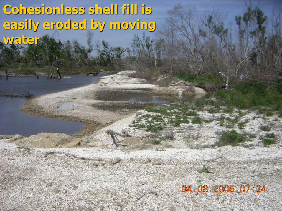
Cohesionless shell fill is easily eroded by moving water

• Surficial erosion of the outboard toe of embankment bordering a borrow area along the western side of the reconstructed MRGO channel; as seen in 2007. This is suggestive of low cohesion fill.

0.1
1
10
100
1000
10000
100000
0.1 1.0 10.0 100.0Velocity (m/s)
S1-B1-(0-2ft)-TW S1-B1-(2-4ft)-SW S2-B1-(0-2ft)-TW
S2-B1-(2-4ft)-SW S3-B1-(2-4ft)-SW S3-B2-(0-2ft)-SW
S3-B3-(0-1ft)-SW S4-(0-0.5ft)-LC-SW S4-(0-0.5ft)-HC-SW
S5-(0-0.5ft)-LT-SW S6-(0-0.5ft)-LC-SW S7-B1-(0-2ft)-TW
S7-B1-(2-4ft)-SW S8-B1-(0-2ft)-TW S8-B1-(2-4ft)-L1-SW
S8-B1-(2-4ft)-L2-SW S11-(0-0.5ft)-LC-TW S11-(0-0.5ft)-HC-TW
S12-B1-(0-2ft)-TW S12-B1-(2-4ft)-SW S15-Canal Side-(0-0.5ft)-LC-SW
S15-CanalSide-(0-0.5ft)-HC-SW S15-Levee Crown-(0-0.5ft)-LT-SW S15-Levee Crown-(0.5-1.0ft)-LT-SW
Very High
Erodibility
I
High
Erodibility
II Medium
Erodibility
III
Low
Erodibility
IV
Very Low
Erodibility
V
Erosion
Rate
(mm/hr)

The key to levees surviving overtopping is the clay content.
Much of the dredged material consisted of organic silt,
which does not have substantive cohesion
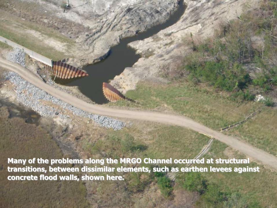
Many of the problems along the MRGO Channel occurred at structural transitions, between dissimilar elements, such as earthen levees against concrete flood walls, shown here.
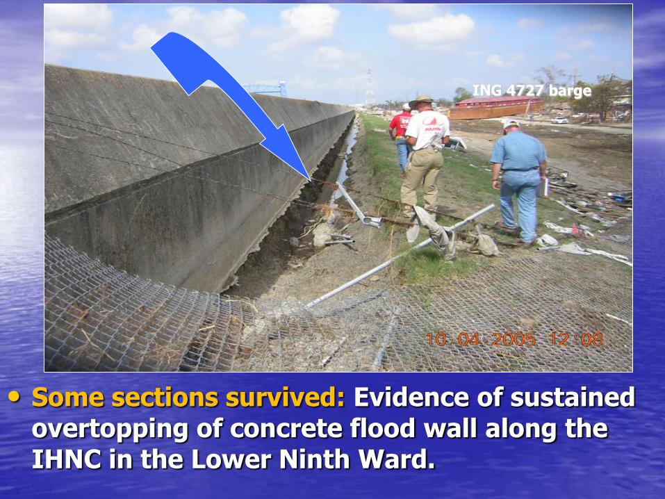
• Some sections survived: Evidence of sustained overtopping of concrete flood wall along the IHNC in the Lower Ninth Ward.
ING 4727 barge

• Overtopping scour holes along landside of flood wall on west side of the IHNC. Note broken wall in background. A splash pad on inboard side could have prevented this undercutting for less than 0.5% of the flood wall cost, making the structure “Class 3 survivable.”
Unraveling the 17th Street Canal
Translational Failure Sequence
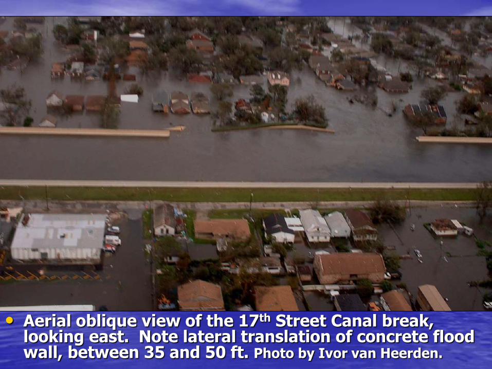
• Aerial oblique view of the 17th Street Canal break, looking east. Note lateral translation of concrete flood wall, between 35 and 50 ft. Photo by Ivor van Heerden.

EPA, 2005
The most recently constructed elements
of the city’s flood control infrastructure,
built in the mid 1990s, performed
miserably.

Geologic profile for the 17th St Canal flood wall prepared by Corps’
New Orleans District office in 1990. Three of four holes in vicinity of
the 2005 failure (spaced 500 ft apart) had zero sample recovery.
These contacts were projected and the sheet pile tips designed,
accordingly.
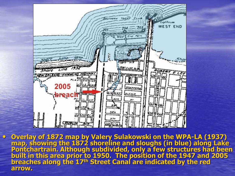
• Overlay of 1872 map by Valery Sulakowski on the WPA-LA (1937) map, showing the 1872 shoreline and sloughs (in blue) along Lake Pontchartrain. Although subdivided, only a few structures had been built in this area prior to 1950. The position of the 1947 and 2005 breaches along the 17th Street Canal are indicated by the red arrow.
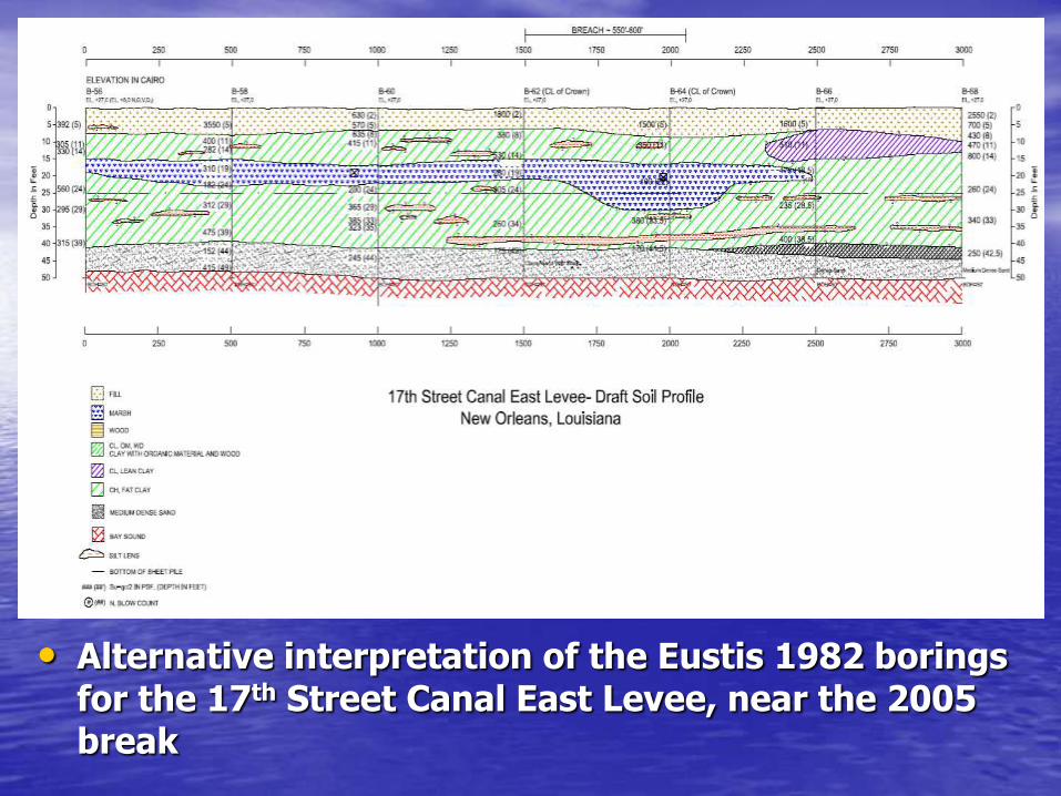
• Alternative interpretation of the Eustis 1982 borings for the 17th Street Canal East Levee, near the 2005 break
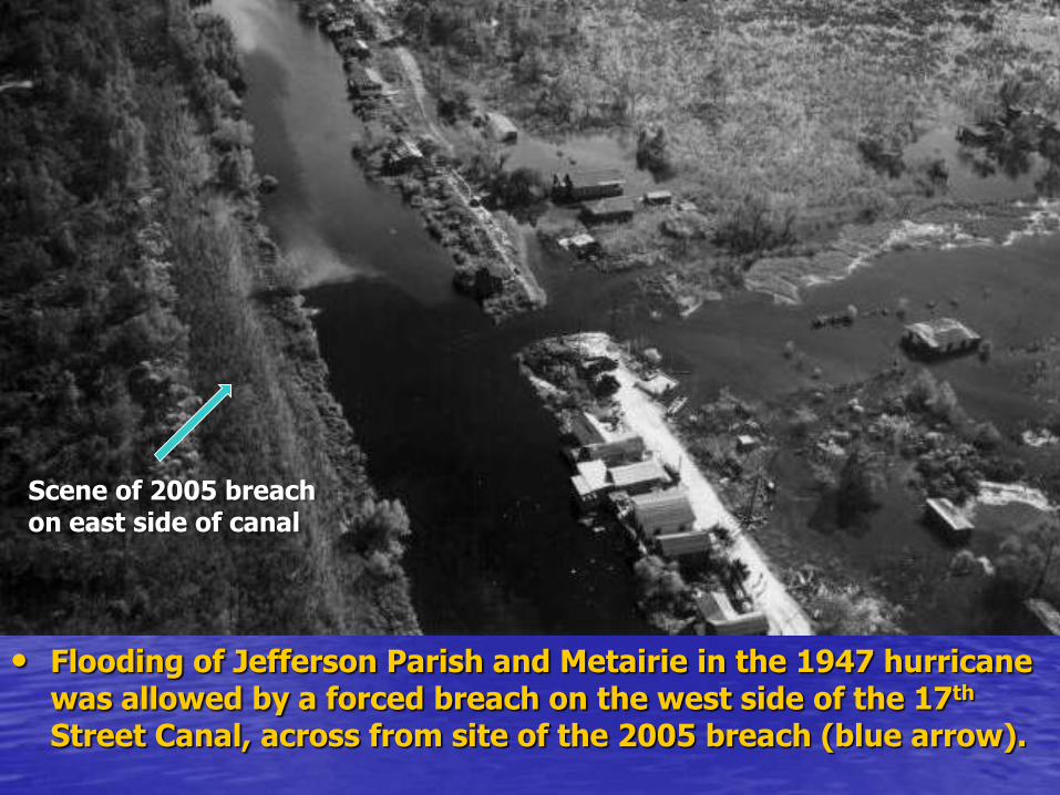
• Flooding of Jefferson Parish and Metairie in the 1947 hurricane was allowed by a forced breach on the west side of the 17th Street Canal, across from site of the 2005 breach (blue arrow).
Scene of 2005 breach on east side of canal
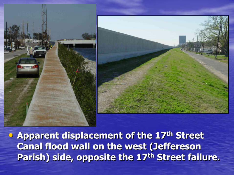
• Apparent displacement of the 17th Street Canal flood wall on the west (Jeffereson Parish) side, opposite the 17th Street failure.

• Stratigraphic interpretations across the 17th Street Canal breach. The swamp much appeared to be thinning northerly, as does the underlying Pine Island Beach Trend. The lacustrine clays appear to thicken southward, as shown.
• The approximate positions of the flood walls (light blue) and canal bottom (dashed green) are based on information provided by the Corps of Engineers.
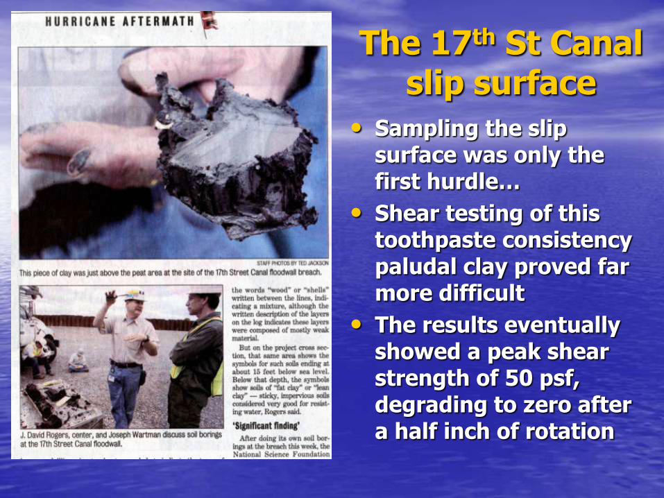
The 17th St Canal slip surface
• Sampling the slip surface was only the first hurdle…
• Shear testing of this toothpaste consistency paludal clay proved far more difficult
• The results eventually showed a peak shear strength of 50 psf, degrading to zero after a half inch of rotation

Lab Vane Test Results
for 17th Str. Canal, East Bank
0.00
0.10
0.20
0.30
0.40
0.50
0.60
0.70
0.80
0.90
1.00
0 1 2 3 4 5 6 7 8 9 10 11 12
Displacement (in)
τ/S
u
CH/OH, OCR=1
CH, OCR= 2 to 3
Marsh, OCR=1
Marsh, OCR=1.5
Lab Vane Test Results
for 17th Str. Canal, East Bank
0
100
200
300
400
500
600
700
800
0 1 2 3 4 5 6 7 8 9 10 11 12
Displacement (in)
Shear
Str
ength
, τ
(psf)
CH/OH, OCR=1 to 3
Marsh, OCR=1
Marsh, OCR=1.5
17th Street Canal: Sensitivity of the Sensitive Organic Clay within the Marsh Stratum vs. Sensitivity of the Deeper Gray Clay (CH)
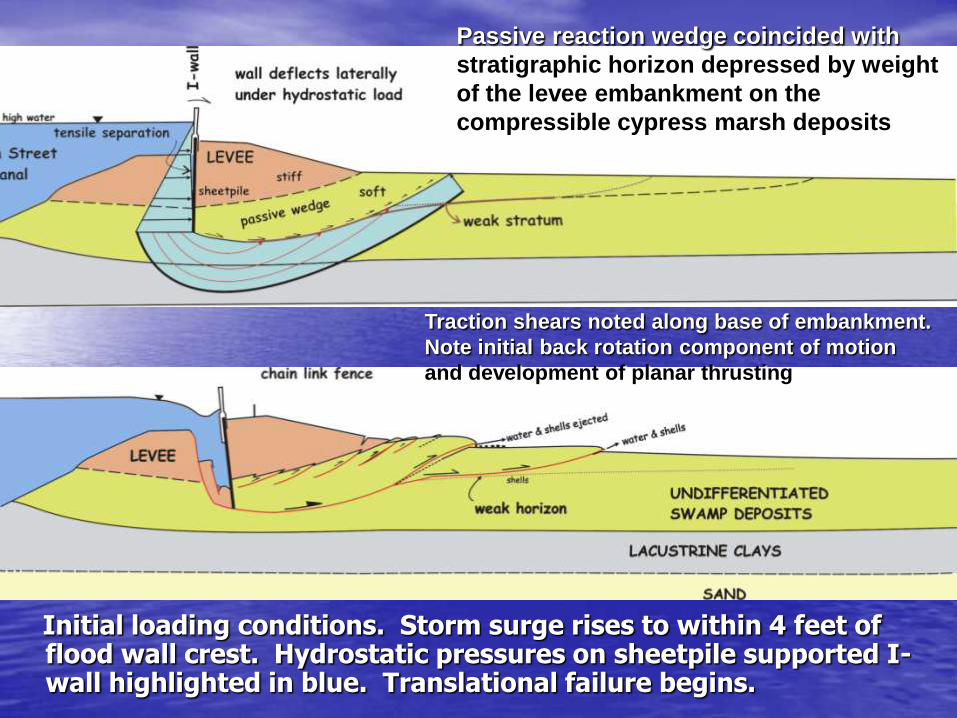
Initial loading conditions. Storm surge rises to within 4 feet of flood wall crest. Hydrostatic pressures on sheetpile supported I-wall highlighted in blue. Translational failure begins.
Traction shears noted along base of embankment.
Note initial back rotation component of motion
and development of planar thrusting
Passive reaction wedge coincided with
stratigraphic horizon depressed by weight
of the levee embankment on the
compressible cypress marsh deposits

Progression of translational failure sequence. Multiple thrust sheets develop in partially saturated crust, comprised of sandy fill over organic cypress swamp deposits. The upper crust buckles like a rug being rolled up.

Final stages of translational failure sequence. Lower section shows failed levee after 51 feet of displacement. The void was quickly backfilled with gravel as part of sealing the breach.
drainage canal
Some sheetpile supported I-walls fell backward; others fell forward
2 3 4
8 7 6 5
9 10 11 12 13
17 16 15 14
1
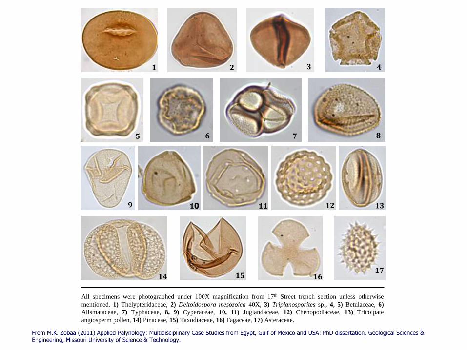
All specimens were photographed under 100X magnification from 17th Street trench section unless otherwise
mentioned. 1) Thelypteridaceae, 2) Deltoidospora mesozoica 40X, 3) Triplanosporites sp., 4, 5) Betulaceae, 6)
Alismataceae, 7) Typhaceae, 8, 9) Cyperaceae, 10, 11) Juglandaceae, 12) Chenopodiaceae, 13) Tricolpate
angiosperm pollen, 14) Pinaceae, 15) Taxodiaceae, 16) Fagaceae, 17) Asteraceae.
From M.K. Zobaa (2011) Applied Palynology: Multidisciplinary Case Studies from Egypt, Gulf of Mexico and USA: PhD dissertation, Geological Sciences & Engineering, Missouri University of Science & Technology.
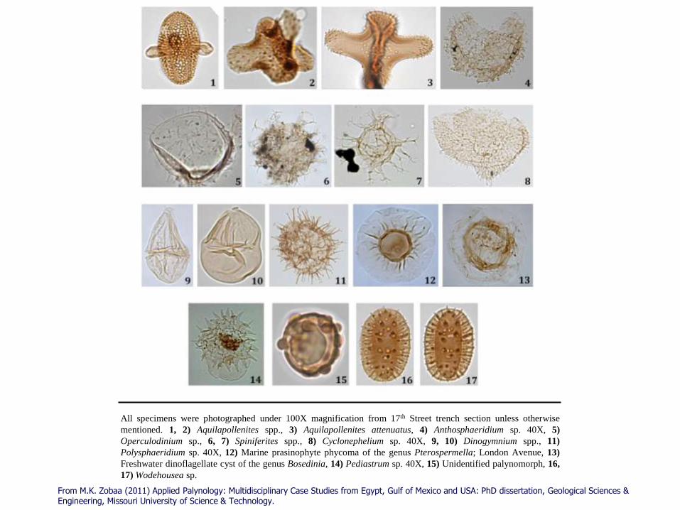
All specimens were photographed under 100X magnification from 17th Street trench section unless otherwise
mentioned. 1, 2) Aquilapollenites spp., 3) Aquilapollenites attenuatus, 4) Anthosphaeridium sp. 40X, 5)
Operculodinium sp., 6, 7) Spiniferites spp., 8) Cyclonephelium sp. 40X, 9, 10) Dinogymnium spp., 11)
Polysphaeridium sp. 40X, 12) Marine prasinophyte phycoma of the genus Pterospermella; London Avenue, 13)
Freshwater dinoflagellate cyst of the genus Bosedinia, 14) Pediastrum sp. 40X, 15) Unidentified palynomorph, 16,
17) Wodehousea sp.
From M.K. Zobaa (2011) Applied Palynology: Multidisciplinary Case Studies from Egypt, Gulf of Mexico and USA: PhD dissertation, Geological Sciences & Engineering, Missouri University of Science & Technology.

Radiocarbon dating data and percentage distribution of selected palynomorph categories recorded from
17th Street Canal section. For better illustration, curves represent freshwater elements, Aquilapollenites spp.
and fern spores are exaggerated 10 times while that of the marine elements is exaggerated 5 times. The
shaded zone represent the proposed period of major devastation as a result of sever marine surge
Palynomorph Analysis and Radiocarbon Dating

A climatic shift from subtropical-temperate to tropical conditions is suggested based on the gradual replacement of Pine forest by Taxodium forest with time in the study area A strong marine surge(s) was/were detected at depths between 18 to 33 ft, based on the presence of exotic older fern spores and Aquilapollenites taxa, commonly associated with marine dinoflagellate cysts
Paleoclimatic deductions
From M.K. Zobaa (2011) Applied Palynology: Multidisciplinary Case Studies from Egypt, Gulf of Mexico and USA: PhD dissertation, Geological Sciences & Engineering, Missouri University of Science & Technology.
CONCLUSIONS
Nothing happened in New Orleans that couldn’t have happened to any of us… working in other parts of
the country…
Rogers Rules of Geoengineering - 1
• Geology is married to geotechnical engineering.
If you miss something in the geologic characterization, your engineering expertise may not save you
• There are no ruler straight lines in geology. If your cross section has ruler straight lines, you probably did a poor job of geologic characterization
•Its what you don’t recover in the borings that’s usually the most important material
• Always re-drill holes bereft of any sample recovery; every assumption you make is fraught with uncertainty

Rogers Rules of Geoengineering - 2
• In areas with complex stratigraphy, it is often
necessary to construct multiple cross sections, especially, along the trend of former flow paths (channels); NOT simply perpendicular to the dike you are analyzing.
• When performing slope stability assessments, never allow yourself to AVERAGE the soil shear strength – you’ll get the wrong answer
• Critical peer review ALWAYS a good idea; fresh look by fresh eyes….
• One geologist on the team may not prevent mis-interpretations of geology; competence depends on training and experience with similar geomorphic settings

This lecture will be posted on my Missouri S&T website as a
pdf file for easy downloading. It is not copyrighted
www.mst.edu/~rogersda/levees/
Mississippi Delta Region