Bachelor Thesis, MdH - Research in Innovation, Design and … · · 2014-11-11Bachelor Thesis...
44
-
Upload
vuongkhuong -
Category
Documents
-
view
222 -
download
4
Transcript of Bachelor Thesis, MdH - Research in Innovation, Design and … · · 2014-11-11Bachelor Thesis...

MdH UniversityIDT
Bachelor Thesis
Mobile Virtual RealityEnvironment in Unity 3D
Patrick Sjöö
Supervisor: Daniel KadeExaminer: Rikard Lindell
Västerås, SwedenNovember, 2014
Abstract I
Abstract
This report is a contribution to an existing research project, which works on supporting mo-tion capture actors by improving their immersion and experiences through an augmentedreality setup. The problem de�nition is that a motion capture studio, up to now, does notprovide a large scenery for an actor. A motion capture scene is made almost entirely out ofprops and actors wearing motion capture (mocap) suits. To set the stage and environmentthere is usually a director explaining what the props are and what the situation is. Therest lies in the hands of the actors to imagine the scene.This project provided the controls for viewing a virtual environment using a smartphone
with an Android operating system. The result was an application containing a virtualworld that the user could look and walk around in using the smartphone's gyroscope andaccelerometer respectively. This shall help the actor to get a better view of the surroundingworld in which he or she is supposed to act in. The phone was connected to a pico projectorand both devices were mounted on the user's head to get all needed input such as turning,tilting and physical movements. The phone can also be mounted in several positions whichcan be changed in real time. Some user testing was made to see how users handled thedevices and what they thought of the application.
Bachelor Thesis Patrick Sjöö

Acknowledgements II
Acknowledgements
There are two people I would like to give thanks to:First of all, Daniel Kade, for answering all my questions I had during the course of thisproject. Also a big thanks for providing me with an awesome level to walk around in andlots of other �xes and advice.Secondly, I would like to give a hearty thanks to So�e Allared for her never ending
support and motivation before, during and surely after this project. I would probablynever have gotten this project if she hadn't motivated me into it. My deepest thanks toyou.I would also like to thank Pepper, the �nest dog I've ever had in my life, for putting
up with me during the long days of coding, testing and problem solving. Always showingconstant love and loyalty, and for getting me out of my chair when things became tiresome.
Västerås, November 2014
Patrick Sjöö
Bachelor Thesis Patrick Sjöö

Table of Contents III
Table of Contents
Abstract I
Acknowledgements II
Table of Contents IV
List of Figures V
1 Introduction 1
2 State-of-the-art 2
3 Research question and problem analysis 7
4 Method 8
5 Terms 10
5.1 Vectors . . . . . . . . . . . . . . . . . . . . . . . . . . . . . . . . . . . . . . 105.2 Quaternions . . . . . . . . . . . . . . . . . . . . . . . . . . . . . . . . . . . . 105.3 Euler angles . . . . . . . . . . . . . . . . . . . . . . . . . . . . . . . . . . . . 105.4 C# . . . . . . . . . . . . . . . . . . . . . . . . . . . . . . . . . . . . . . . . . 115.5 Character controller . . . . . . . . . . . . . . . . . . . . . . . . . . . . . . . 115.6 Blender . . . . . . . . . . . . . . . . . . . . . . . . . . . . . . . . . . . . . . 115.7 Frame rate and frames . . . . . . . . . . . . . . . . . . . . . . . . . . . . . . 115.8 High-pass and low-pass �lters . . . . . . . . . . . . . . . . . . . . . . . . . . 115.9 Gyroscope . . . . . . . . . . . . . . . . . . . . . . . . . . . . . . . . . . . . . 125.10 Accelerometer . . . . . . . . . . . . . . . . . . . . . . . . . . . . . . . . . . . 12
6 Discussion of choices 13
6.1 Phone . . . . . . . . . . . . . . . . . . . . . . . . . . . . . . . . . . . . . . . 136.2 Game engine . . . . . . . . . . . . . . . . . . . . . . . . . . . . . . . . . . . 13
6.2.1 UDK . . . . . . . . . . . . . . . . . . . . . . . . . . . . . . . . . . . . 136.2.2 Unity . . . . . . . . . . . . . . . . . . . . . . . . . . . . . . . . . . . 14
6.3 Mounting the device and projector . . . . . . . . . . . . . . . . . . . . . . . 146.3.1 Position . . . . . . . . . . . . . . . . . . . . . . . . . . . . . . . . . . 146.3.2 Mounting . . . . . . . . . . . . . . . . . . . . . . . . . . . . . . . . . 16
7 Implementation 18
7.1 Setup . . . . . . . . . . . . . . . . . . . . . . . . . . . . . . . . . . . . . . . 187.2 Code design . . . . . . . . . . . . . . . . . . . . . . . . . . . . . . . . . . . . 18
Bachelor Thesis Patrick Sjöö

Table of Contents IV
7.3 Program �ow . . . . . . . . . . . . . . . . . . . . . . . . . . . . . . . . . . . 197.3.1 Initialization . . . . . . . . . . . . . . . . . . . . . . . . . . . . . . . 207.3.2 Input . . . . . . . . . . . . . . . . . . . . . . . . . . . . . . . . . . . 217.3.3 Update . . . . . . . . . . . . . . . . . . . . . . . . . . . . . . . . . . 217.3.4 Draw . . . . . . . . . . . . . . . . . . . . . . . . . . . . . . . . . . . . 21
7.4 Step algorithm . . . . . . . . . . . . . . . . . . . . . . . . . . . . . . . . . . 227.5 Rotation algorithm . . . . . . . . . . . . . . . . . . . . . . . . . . . . . . . . 247.6 Finding phone mounting positions . . . . . . . . . . . . . . . . . . . . . . . 257.7 Interface . . . . . . . . . . . . . . . . . . . . . . . . . . . . . . . . . . . . . . 267.8 Level . . . . . . . . . . . . . . . . . . . . . . . . . . . . . . . . . . . . . . . . 28
8 User tests 30
9 Conclusion 34
10 Future Work 35
Bibliography 36

List of Figures V
List of Figures
2.1 The Oculus VR showing it's capability to separate the user's vision fromeverything else. Source: WikiMedia Commons . . . . . . . . . . . . . . . . . 2
2.2 Picture showing the similarities between the Avegant VR Retinal displayand a regular pair of sunglasses. Source: CNET . . . . . . . . . . . . . . . . 3
2.3 The Durovis Dive mounting device is pictured to show how the phone isbeing mounted and how the lenses are placed. Source: Durovis . . . . . . . 4
5.1 Picture to better visualize how a gyroscope works. All the circles in thepicture represent an axis that you can spin around. Source: WikiMedia
Commons . . . . . . . . . . . . . . . . . . . . . . . . . . . . . . . . . . . . . 12
6.1 Picture showing the phone mounted on the side of the head with the picoprojector on top . . . . . . . . . . . . . . . . . . . . . . . . . . . . . . . . . 15
6.2 One of the ideas on how to mount the device. The picture is showing aheadstrap with two straps for added support. Source: GoPro . . . . . . . . 16
6.3 The �nished version of the prototype to get a better understanding of howit looks. This was used in all tests afterwards. Featuring the creator of thecap as well . . . . . . . . . . . . . . . . . . . . . . . . . . . . . . . . . . . . . 17
7.1 This picture shows a UML (Uni�ed Modeling Language) diagram over howall objects and scripts are connected. It also shows the scripts' variables andmethods with their respective types and return types . . . . . . . . . . . . . 19
7.2 Picture showing how a game loop is built. To break the loop and exit theprogram, the user needs to shut it down - most likely through some kind ofinput. Picture was created with an online UML diagram tool . . . . . . . . 20
7.3 A picture showing the two di�erent algorithms, the arrows shows whichacceleration is being measured. The left side has the regular algorithmactive and the right side has the WIP algorithm active. The gray arearepresents the smartphone . . . . . . . . . . . . . . . . . . . . . . . . . . . . 24
7.4 Picture showing roughly where the positions are in relation to the user'shead. The �rst one shows the user with the phone on the left side. Thesecond shows the right side. The third shows the phone on top of the user'shead (note that the view is slightly tilted). The last picture shows the phoneon the back, close to the neck. . . . . . . . . . . . . . . . . . . . . . . . . . . 26
7.5 The making of the test level to show in more detail how it looks. The tophalf shows the �rst plane created and cut according to the size of an actualshooting �oor. The bottom half shows the �nal level with textures andlighting. . . . . . . . . . . . . . . . . . . . . . . . . . . . . . . . . . . . . . . 28
Bachelor Thesis Patrick Sjöö

List of Figures VI
7.6 A scene from the �nal test map featuring a guard tower with a special setof trees (they have a di�erent kind of foilage) . . . . . . . . . . . . . . . . . 29
7.7 Another scene featuring a car by a small jungle of bamboo trees . . . . . . . 29
8.1 The diagrams are showing what the testers answered to the questions shownabove them to showcase possible connections between them . . . . . . . . . 31
8.2 Picture shows a diagram of how the testers felt about the realism in ourapplication . . . . . . . . . . . . . . . . . . . . . . . . . . . . . . . . . . . . 32
8.3 Picture of a user testing the application in a small conference room . . . . . 33

1 Introduction 1
1 Introduction
Motion capture today makes animation more realistic than ever before, and it's commonlyused in media, on the internet and in video games[18]. Motion capture means that you usereal actors with markers attached to them (usually on a suit similar to wet suits) to tracktheir movements, and sometimes facial expressions, to create animations, which are laterput on something else - like a video game character. One of the problems that comes upduring the acting is the fact that unlike a real movie set, there is usually no real props totell the actors anything about the location or happenings around them, there are only theinstructions from a director. The aim of this project was to contribute to a bigger researchproject, which goal was to create a more immerse environment for motion capture actors.This thesis was made to provide the controls for displaying a virtual scenery for a mo-
tion capture environment and see if it was possible to achieve it using a regular phone. Itdescribes our project in terms of code, design and the development of the resulting appli-cation. It also tells about the algorithms used for both rotation and movement, issues withdesign, discussions and comparisons with other projects and tools, the implementation andeventual cuts of features.We wrote this application to make the whole set very �exible and compact, whilst trying
to have it as powerful as possible, to provide a visual contribution to the bigger project.One requirement for this project was that it had to be made using a game engine. Withthis program, you can take almost any Android phone (not counting those that lack agyroscope), install it and have it up and running in a couple of minutes. Because it allexists on a smartphone, there are nearly no limits for where it can be used. Everything isdone with free software.At the end, we had a working prototype application which could be used to walk and
look around using only the phone. Connected to a pico projector mounted on top of theuser's head, the user could get a bigger picture displayed in front of him or her. The phonecould be mounted on any side of the head, and the application could be adjusted to thenew position whilst running with the push of a button.
Bachelor Thesis Patrick Sjöö

2 State-of-the-art 2
2 State-of-the-art
There exists some technology and products that have similarities with this project. The�eld of virtual and augmented reality evolves all the time, always producing better hard-ware and new technologies[23][24].For instance, there is the Oculus VR[10], which is a virtual reality headset designed for
gaming. It features a screen that is mounted in front of the user's head. It uses severalsensors such as a gyroscope, an accelerometer and a magnetometer to supposedly give itabsolute head tracking relative to earth, without drag. It shuts out the rest of the user'sview so only the device's screen is visible. To date there hasn't been an o�cial release forconsumers, but there exists developer kits and games need to be speci�cally programmedto work with the Oculus VR. When comparing it to this project, it uses similar typesof sensors to achieve it's intense atmosphere, but as mentioned before it lacks an o�cialrelease. Also, the few games it has support for, uses a controller to move around and thedevice is only for looking around in the world. This project wants to be able to movearound using the accelerometer as well, and not depend on a controller. Oculus VR alsohas to be powered by another source than it's own, which a phone solves by having it'sown battery. It was also an inspiration on how to mount the device for our own project.
Figure 2.1: The Oculus VR showing it's capability to separate the user's vision from ev-erything else. Source: WikiMedia Commons
Bachelor Thesis Patrick Sjöö
2 State-of-the-art 3
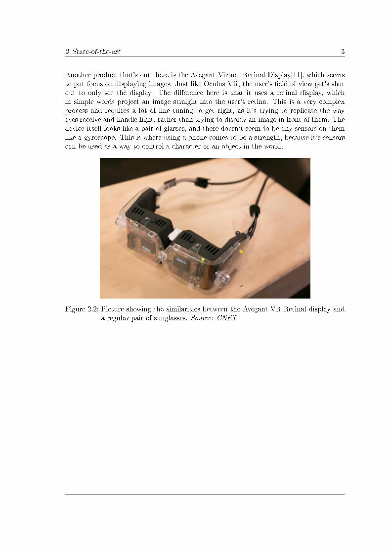
Another product that's out there is the Avegant Virtual Retinal Display[11], which seemsto put focus on displaying images. Just like Oculus VR, the user's �eld of view get's shutout to only see the display. The di�erence here is that it uses a retinal display, whichin simple words project an image straight into the user's retina. This is a very complexprocess and requires a lot of �ne tuning to get right, as it's trying to replicate the wayeyes receive and handle light, rather than trying to display an image in front of them. Thedevice itself looks like a pair of glasses, and there doesn't seem to be any sensors on themlike a gyroscope. This is where using a phone comes to be a strength, because it's sensorscan be used as a way to control a character or an object in the world.
Figure 2.2: Picture showing the similarities between the Avegant VR Retinal display anda regular pair of sunglasses. Source: CNET

2 State-of-the-art 4
Yet another implementation for both Android and iOS is a project called Dive[12]. It usesa regular smartphone and a plastic frame in which you place it. The frame contains twolenses which provide the user with a better �eld of view. It makes use of the phone'ssensors to look around in di�erent worlds. The are even versions that supports phones notequipped with a gyroscope, although those provide a very limited (if any at all) experience.There exists a game for Dive, which describes it as a "Run and Jump"-game. When lookingat how the movement is handled, it's done by looking at a certain object long enough forit to turn green. At that point, the user start moving forward at a constant speed inthe game. Also, Dive can only be played in landscape mode on the phone, given that itattempts to show two separate images to create a 3D-e�ect. In our project, we wanted tobe able to run the application in both landscape and portrait mode.
Figure 2.3: The Durovis Dive mounting device is pictured to show how the phone is beingmounted and how the lenses are placed. Source: Durovis

2 State-of-the-art 5
A project that has a few similarities with this project is a project named "`AR StreetView"'[7], which uses Google Maps's street database matched with a smartphone's GPSand camera to create a live video of the user's surroundings. The phone itself provides theimage, and the data from the database gives information for certain street names and keylocations. This project comes with a positional problem at times, and uses a gyroscopeand accelerometer to create a pedometer to count the user's steps and in what directionthey go. The di�erence between our project and this one that their sensors are not placedin the phone, but at the waist. Also, there are four required components for "`AR streetview"', namely the software, the database server, an external sensor (which most likelyrefers to the gyroscope and accelerometer) and a UMPC (or laptop PC) with a Bluetoothadapter. In comparison, our project only requires you to have our software installed onyour smartphone equipped with an accelerometer and a gyroscope.A project more focused on motion capture is named "`Practical Motion Capture in Ev-
eryday Surroundings"'[16]. Like our project, it uses sensors mounted on the user to tracktheir movements, and it's designed to capture regular everyday motions - from casualwalking to cooking food. It has good replication of movements and uses gyroscopes, ac-celerometers and ultrasonic sources to measure the movements. The �rst two are bundledtogether on a single chip, whilst the ultrasonic source works on it's own. The chips areplaced on the user's joints and the rest is placed on di�erent parts of the upper body. Allof this data is then stored and processed in a backpack containing a driver box with a harddrive attached through a USB port. One of the more interesting aspects of this projectis the amount of sensors needed to obtain a good quality of movements, as nearly everymotion in the user's body has to be tracked. This project gave an idea on some of thecomplexity involved using gyroscopes and accelerometers for tracking movement.The project REFLCT[19] aims to provide training programs using pico projectors and
retrore�ective surfaces to display images. It utilizes a helmet with one or more pico projec-tors, one or more re�ective surface and some form of tracking, to display individual imagesfor the users. The tracking is made by using a motion capture system to get the camera'sposition, which is then fed to a PC, which provides the correct image. REFLCT mentionshaving a version developed for smartphone using Unity, although tracking is still madethrough WiFi and might possibly be the motion capture system as well. Our project doesnot rely on any other system than the phone itself, even for de�ning it's position, whichwould be the major di�erence between the two.Another take on making a cheap and portable solution for the market in motion capture
is the MuVR[25]. It features a mobile augmented experience and aims to create a cheapsolution. The hardware it utilizes includes an Oculus Rift[10], a Raspberry Pi computer,a smartphone, a Razer Hydra tracking system and a battery pack (with some minor con-nection cables and adapters). The Oculus Rift handles all the visuals, sounds and headmovement. The smartphone provides all locomotion for the movement through the virtualworld, and the Razer Hydra uses electromagnetic tracking to keep track of the body. Thesensor's are read via wi� through the Raspberry Pi and it also supports multiple users tojoin the same world. Just like our project, this one used Unity to develop the virtual worldto walk around in, and does so by making it stereoscopic so everything renders in 3D.Another similar thing is the use of the smartphone's accelerometer to determine whetheror not a user is walking, although the actual results are not mentioned - only speculated.

2 State-of-the-art 6
One of the bigger di�erence is notably the amount of equipment (Our project uses two,whilst the MuVR uses more than six including cables), this naturally leads to a higherrange of sensors as both the Oculus Rift and the smartphone provides separate sets ofdata, potentially leading to higher accuracy in movement tracking. One downside to usingan Oculus Rift for translating actual walking to a virtual world is that the user's visionis strictly limited to that on it's screen, which could lead to hardships if you would wantobjects to interact with (like boxes to climb, or other things to go under).

3 Research question and problem analysis 7
3 Research question and problem analysis
Like every other project, this thesis aims to solve a problem, and this section will give amore detailed description of that.The problem at hand for this thesis comes from an already existing research project,
which is trying to create a more immerse environment for motion capture actors to act in,both through graphics and audio. Usually on a motion capture stage, the actors are putin a scene where every day items are used as props. A director tells them the environmentthey're in, what the props are supposed to resemble (if any) and the events that happen(like explosions). The actors have to take these directions and imagine it in front of them,unlike a real movie set where the props are more or less real and look just like they aresupposed to look in the �nal product. In order to try and make the motion capturestage more real, audio and graphics are added to the stage. This project focuses on thegraphics part, and more speci�cally by providing the controls for an application to viewthe environment that the actor is to see. The problem we're facing comes down to thequestion: "Is it possible to make the controls for displaying a virtual scenery used in amotion capture environment?"What we had to create was some kind of application which could be used in motion
capture, possibly something mobile that would provide the actor with something visualwithout interrupting the regular acting.
Bachelor Thesis Patrick Sjöö

4 Method 8
4 Method
When working on this project, we followed a simple pattern of idea gathering - implemen-tation - testing.As for starting out, we needed to see what else was out there. Has anybody done
something just like this or at least close to what we are trying to achieve? There existedsome projects which had some similarities to our own, although in some cases not designedfor our target group. At the same time as we did the search for similar projects, so for the�rst few meetings we sat down and had a few brainstorming sessions. We already knew theproject had to be made for a phone, so we discussed a lot of ideas on how the applicationcould be designed and also how it would be mounted on the user. When we had decided ona design we were happy to make a prototype of, we started implementing the application.The methods used for working with the implementation has mainly been to use agile
project methods. Agile methods are commonly used in project where time is of the essence,and they're often used in computer projects. Right from the start, we decided to go forSCRUM[6], which focuses on getting a working prototype out as fast as possible to enabletesting on users early. As the projects made progress, new features are added with the usertests in mind. This process of constant evaluation keeps the �nal product close to whatthe user wants, although a lot of the time goes to testing. This method suited us the bestas we wanted to get something to use quickly and tests as soon as possible, and by havinga dynamic work method where the essential features were done �rst, we could focus onmaking more fun and experimental ones if there was any time left over. It's important toknow that SCRUM is a work method, and not a scienti�c method of research.At the start of the implementation, it was all about getting familiar with the development
environment, and after a few weeks the actual development began. Because we wereworking with our own version of SCRUM, we had weekly meetings to constantly check upon the progress of the project. As soon as we had a version that we could run properly,we started testing it inside the group to �nd bugs, design �aws and better algorithms.Eventually a �nal prototype had been �nished to be tested by regular users. The test wascarried out at our university, Mälardalens Högskola, with 6 di�erent persons. All of themwere given time to try out the device and were asked to �ll in a form afterward. Theseresults gave us a very clear picture of how users react to the idea of walking around in avirtual world and how people handle the application the �rst time. The users had somesuggestions on some of the areas where they would like to see the application being usedas well. The tests were evaluated on a qualitative grounds. As there unfortunately wasn'tmore time for testing, a quantitative evaluation simply didn't have enough material. Ina research ethical statement, we made sure that the testers understood that the test wasentirely voluntary and that they could, at any time, abort it. We also made sure the testersknew we weren't testing them, but the application itself.The argumentation method used for this project leans towards inductive reasoning,
which means that we worked from a question, and then try various approaches to reach a
Bachelor Thesis Patrick Sjöö

4 Method 9
conclusion in the end. The reason it's an inductive method is because of the exploratorynature of this project. As there indeed exists other projects with their own conclusionsdoesn't necessarily mean that we will reach the same one, if anything like them at all.This is why we conduct the tests and try a lot of algorithms and di�erent things withour application. In our project, the things connected to this type of reasoning has beenbrainstorming, prototype building and testing - both on ourselves in the work group andwith real users. Through brainstorming we got our ideas on how start the project, which webacked up with what we had found on our state-of-the-art section. To approach our ideasat hand, we tried to construct said ideas and tested them ourselves as well as discussing theresults. If the conclusion came to that it was a good idea, we decided to develop it furtheruntil we had a working prototype, continuously testing it and discussing our �ndings. Theprototype gave us a lot of information on what the limits were both for the hardware andsoftware and the user tests provided us with information if the application could preformaccording to our problem at hand - if it is possible to make the controls for displaying avirtual scenery used in a motion capture environment.

5 Terms 10
5 Terms
This section of the report explains some of the terms used in this project in detail toprovide a common understanding of the terms.
5.1 Vectors
A vector is used all over the world of mathematics, physics and video games. It's usuallydescribed as a line between points and can have an in�nite amount of dimensions, butin almost all cases 2- or 3-dimensional vectors are used. They are usually written as acollection of values and also have a direction and length. For instance, the 2-dimensionalvector (1, 1) can describe a vector that goes from point (0, 0) to point (1, 1). To calculatethis, let's call the �rst point A, and the second point B, then to calculate the vector AB,we need to subtract the point in reverse order. Subtracting vectors basically means thatyou subtract the corresponding positions with each other, which leads to AB = (1-0, 1-0)= (1,1). However, a vector does not always start at (0,0), if A = (0, 2) and B = (2, 2),then we get AB = (2-0,2-2) = (2,0) which shows a vector that goes straight to the rightfor two steps along the X-axis. Vectors always show what direction they travel in and forfar they go, but are not de�ned where they, for example, start. For this reason, you cannot rely solely on vectors to acquire a position. However, if you have a point to describe aposition, then a vector can be added (or subtracted) to change said position. This is whyit's important to understand the di�erence between points and vectors. Vectors are usedimmensely in graphics calculations as well, but will not be discussed in this section.
5.2 Quaternions
To describe an orientation in 3D, or a rotation if you will, one way is to use quaternions[1, 2].They are amongst one of the more complex mathematical terms and when it comes to usingthem in this project, the need to know exactly what they are is not as important as theknowledge of how to use them. In order to understand quaternions fully, an extensiveknowledge of complex numbers is needed, but what one needs to know for this project isthat quaternions are used for any kind of rotation done with the camera.
5.3 Euler angles
When speaking of euler angles, the easiest way to think of them is by using them as regulardegrees in geometry. Euler angles are used to keep track of a rotation along the X-, Y-, andZ-axis and just like regular geometry there's 360 degrees to a full lap. So if a model has arotation vector with euler angles (0, 0, 0) it's not rotated at all from it's native or defaultrotation and should it have something in the nature of (90, 0, 180) we can read that it's
Bachelor Thesis Patrick Sjöö

5.4 C# 11
rotated 90 degrees along the X-axis, and 180 degrees along the Z-axis. Euler angles can beused instead of quaternions.
5.4 C#
C# is an object oriented programming language created by Microsoft. It's used in manyprograms, and has it's roots in the C/C++ language. It focuses heavily on object orientedprogramming, which means that the program is structured with classes which acts asmain templates. From those classes, objects are created and interacted with during actualruntime of the program/application. For was the program language used for scripting.
5.5 Character controller
A character controller[4] is a special kind of game object in Unity. It features a collidershaped like a capsule, prede�ned methods for movement and other useful settings likechanging the height of a step, to decide how high an edge has to be in order to step over itwithout having to jump. It doesn't come with a model, but one can be assigned if needed.For this project, a character controller is used to move around in the environment, as asimulated user.
5.6 Blender
Blender[5] is a free, open source 3D-model creator. With Blender you can create 3D-modelswith animations and textures. It has some very powerful features, but has a rumor to havea high learning curve. It has been used in both movie projects and television commercials.This program was used to create the �rst test/debug map.
5.7 Frame rate and frames
Frame rate is the speed in which something is updated (commonly used in games) and ismeasured in frames per second (fps). Most games to date use either 30 or 60 fps.
5.8 High-pass and low-pass �lters
Just as the name tells, a high-pass or low-pass �lter is a �lter that only lets certain valuespass. The reason why something should have a �lter like this is to get a more consistentset of data from a constant streams and are used in the electric and audio industry. Inthis project, a high-pass �lter is used to get rid of jittery shaking when looking around theworld.

5.9 Gyroscope 12
5.9 Gyroscope
A gyroscope is a device that measures orientation. They're used all over the world wherethe need for stability is high and you don't want things to fall over. Trains, planes, rockets,ships, pointing devices and a lot more use them. For this project, it makes the phone awareof how it's turned and that's essential for looking around in the world.
Figure 5.1: Picture to better visualize how a gyroscope works. All the circles in the picturerepresent an axis that you can spin around. Source: WikiMedia Commons
5.10 Accelerometer
An accelerometer[8] is a device that measures force applied to it and is used in lots ofareas, all ranging from vibrations in machines to safety features like airbag deployment.The values it produces can be translated into a vector, which can be used to get a senseof direction and acceleration. The accelerometer is a�ected by g-force and can detect verysmall and big changes in force. For instance, an accelerometer laying on still on a �atsurface will register the earth's gravity pulling it down. Therefore, gravity always have tobe taken into consideration when reading values from the accelerometer. The ones used inmodern phones can pick up extremely small changes (like the small trembles in your handwhen you try to hold the phone perfectly still) to very big ones (like very violent shakes).In this project, the accelerometer is used to get the user's direction.

6 Discussion of choices 13
6 Discussion of choices
In this chapter, discussions about di�erent choices is the topic. Everything from enginesto how to fasten the device on the intended user.
6.1 Phone
When the project started, we were handed a Samsung Galaxy S4 Mini. The reason for thisis the fact that it gives amongst some of the best performance to cost ratio as of writingtime. There are other phones that have the same kind of sensors, and even more to boot,but either they're more expensive or they're bigger in size. The S4 Mini provides us withthe sensors we need, contains the speci�cations needed to run the application, a size thatis very easy to manage and is also very light weight. The S4 Mini also has Android (ver.JB 4.2.2) as an operating system, which was a requirement to begin with.
6.2 Game engine
6.2.1 UDK
UDK[9] (Unreal Development Kit) is a software used to create 3D applications and usesthe Unreal Engine to render it's graphics. The Unreal Engine has received awards for it'sadvanced graphics and can be seen in many video games and movies. It exists for mostavailable platforms and is in many ways similar to Unity. The reason for choosing Unityover UDK is because Unity seemed the easiest to develop in, as the amount of learning waspractically none at all. One of the advantages Unity has is the method of importing models,scripts or basically any asset you want - you simply drag and drop what you want intoyour project and the program refreshes your folders and keeps track of it. Unity also keepstrack of any changes made from outside programs, such as editing a script or texture withanother program. UDK uses it's own packaging type whenever you import your assets,which may not be self explanatory to somebody who is using UDK the �rst times. UDKalso has the disadvantage to not being able to read as many �le formats as Unity. Bothsoftwares have a free license for educational purposes and non-commercial publishing, butif you want to publish your work commercially (i.e make money of it), there are a fewprices to be paid. You are allowed to publish games with Unity's free version, providedthat you are not a commercial entity with an annual gross revenue over a certain limit,although it comes with limited graphics and some limited features. For instance, there isno real time shadows in Unity's free version. The Pro version of Unity provides you withall features, but at a price. UDK requires you to get a license from the start if you want topublish something, then if you make more than a certain amount of money you will haveto pay a royalty fee to them.
Bachelor Thesis Patrick Sjöö

6.3 Mounting the device and projector 14
6.2.2 Unity
Unity[3] is a scene creator. The layout has similarities to some 3D-modeling programs,but the key di�erence is that Unity is mainly used to create and connect environmentsusing models built in a 3D-modeling program, such as Blender[5] och Maya. Unity canimport almost any model of almost any known �le type and features a project viewer thatautomatically refreshes every time something is imported or changed outside the programitself. The program is free for educational and non-commercial purposes, it can develop onPC and Mac and it can publish to almost any known operating system or modern gameplatform. This was the software used to develop the project, mainly for it's easy learningcurve and publishing, but also because it's free in almost every aspect. It has some prettypowerful tools and graphics as well, although it may not always match the cutting edgetechnology as of writing this (which would then be the Unreal Engine). Another thingthat was good about Unity was that the scripts could be written in C#, which was thelanguage the group had the most experience of.
6.3 Mounting the device and projector
There were a few ideas on where and how to place the mobile device and the pico projectoron the head. Naturally, it had to be the head, otherwise the movements of looking aroundwould be impossible to imitate. As for actually getting the devices to stick to their places,there were some ideas as well.
6.3.1 Position
There were three positions in general that had the most sense in terms of performance,the �rst one being �at on top of the head with the screen facing up. This position gives avery good set of data from the user's movements, as the phone clearly follows all the turnsand tilts. The top of the head is also (in most cases) a �at surface to strap the phone to.When we started tests with this position, it quickly became clear that if you wanted tohave a good center of gravity for your head, you would probably have to stack the phoneon top of the projector. The good thing about having them tight together is that you getsomething very compact to use, the downside is that it becomes a bit bulky to look aroundwith (at least with the ways we tested it). Another thing worth noting is that the compassof your device goes haywire due to the very small magnetic �eld the projector produceswhilst running.

6.3 Mounting the device and projector 15
The second position that was thought up was to place the phone on the side of your head,and the projector on the other. This position gives a good translation of tilts and turns,as well as a good weight distribution, as you have one device on either side of the head.Just as with the top of the head, the side is also a �at place where you can secure thephone and projector somewhat easily. The phone is placed in landscape view when in thisposition, and another plus is that the Android OS automatically corrects the axes so theypoint the right way (meaning their default directions).
Figure 6.1: Picture showing the phone mounted on the side of the head with the picoprojector on top
The third position was to place the phone the back of your head, near the neck. Thisposition gives an average reading from tilts and turns, but a very good upside to it is thatyou get a lot of weight of your head. The biggest problem is probably when you want tolook up, because the phone gets stuck and hinders the head from moving freely.

6.3 Mounting the device and projector 16
6.3.2 Mounting
When it comes to mounting the devices, it should sit tight enough so that it doesn't getthrown around too much, but also it shouldn't cause the wearer any harm or discomfortas it could a�ect the performance of the user. We sat down and brainstormed some simpleand di�erent ideas to use. One of the ideas that came up early was to put the phoneunder a cap, or perhaps sew a "pocket" onto a cap where the phone will be placed. Duringtesting with having the phone completely unsecured under a cap showed that it worked,but as a regular cap produce little to no grip for the actual phone. This was expected,but gave a good idea of how using a simple cap could prove to be a simple solution to theproblem of mounting the device.Another idea was to use a simple strap, which usually comes with normal headlamps.
Most of those straps sit on your head using only one band, or two which makes a wire-frame cap. This idea could be extended to secure the device from di�erent directions, forinstance you could have one strap going around the side of your head, and another goingunderneath your chin.Ultimately when deciding position and method of mounting, the decision was made to
put the phone on the side of the head. It yielded better and more stable results in ourtesting, and also because of the ability to put a strap around the head via the chin. Forthe prototype that was used in our tests, we used a wool cap instead of a head strap. Asfor the projector, it had to be on top of the head (like the picture above), this was dueto the projector providing a better image when it was on top. When it was on the side,the eye that had the projector closest had a sharp and clear image, whilst the other had amore faded one. This ultimately lead to a bad image to look at and the decision was madeto always have the projector on top.
Figure 6.2: One of the ideas on how to mount the device. The picture is showing a head-strap with two straps for added support. Source: GoPro
This was because we wanted to try it out and it sounded simple enough enough to eithersew a pocket into, or even use duct tape to hold everything into place. What we ended upwith as a prototype was a regular wool cap that had holes in the folded end to be able toplug cables in easier. The projector was taped to the top of the cap, and the phone wassecured on whatever side was needed using a tiny amount of tape as well.

6.3 Mounting the device and projector 17
The reason to why mounting the device securely (and preferably comfortably) is due toactivity it's supposed to be used as. The user (ultimately motion capture actors) shouldbe able to turn his or her head quickly, or be able to walk/run or even climb without thedevice falling o� or being displaced. The wool cap was created by Daniel Kade, a PhDStudent at Mälardalens Högskola - the university this project was carried out at.
Figure 6.3: The �nished version of the prototype to get a better understanding of how itlooks. This was used in all tests afterwards. Featuring the creator of the capas well

7 Implementation 18
7 Implementation
7.1 Setup
In order to start writing scripts for this, we needed a program to write the code in. Unityhas the comfortable option of having MonoDevelop[13] built into it, and you can writeall the code in three di�erent languages; C#, Java or Boo (which is based on the morepopular language Python). Another feature you can from using the built in version ofMonoDevelop is due to all libraries connected to Unity[3] are at the programmers disposal,through these you can access the phone's sensors and read their values. In layman's terms,the connection between the phone's sensors and the program is all in the code. As fordrawing the world on the phone's screen, that's all done in Unity.When it comes to holding everything together, we have Unity. It uses scenes to hold
everything that is used in an application, everything from models and object and entirelevels to scripts and code. Apart from that, it also handles organization by keeping trackof the objects and their relations. Such a relation can be that one object is a child toanother object. This makes this object keep the same position, scale and other propertiesshould the parent be moved or changed. These relations are viewed as a hierarchy withthe parents always being higher than their children.At the end of it all you want to build the program with levels, models and code into
one big thing, Unity handles that part as well by packaging everything (called assets) andcreating the necessary installation �le needed.
7.2 Code design
The design for the actual code was at �rst to try to take advantage of the strong objectorientation in C#. When later faced with the problem at hand, it turned out that itwould most likely be either illogical, or too much work. Usually when coding with objectorientation, the goal is to have logic objects that contain logical variables. An examplewould be if a class called "Person" was created. Some logical variables could be things like"Name", "Age" and not "Fur color" or "Brand". Also when using object orientation, thestrength lies in being able to create unique objects from that particular class.In this project's case, there's only three things that are worked with; the character
controller[4], the main camera and the environment (or level). As there won't be anycreation of another character controller or camera, the need for speci�c classes doesn'texist because we only want one of each. So to solve the problem at hand of designing thecode, the decision was made to create one script for each one of the controllable objects,which ended up being three; the character controller, the main camera and the menu. Thecharacter controller's script was to handle everything that was connected to movement ofthe character itself using the accelerometer and all the eventual calculations. The camera's
Bachelor Thesis Patrick Sjöö

7.3 Program �ow 19
script had all the code for looking around in the world using the gyroscope, it also does allthe o�set calculations so that the camera is turned right when switching between di�erentviews. The menu's script displays the HUD with all the menus and debug values whentesting is done. One thing of importance with this script is that it doesn't have it's ownobject to be attached to it, but on the other hand it doesn't matter where it's placed,because the script only makes use of the "OnGUI" method, which is a global methodavailable in any script created. As such, the menu's script is attached to the charactercontroller. The menu's script is also responsible for input from the phone's buttons, likeexiting the application was a certain button on the phone is pressed.
Figure 7.1: This picture shows a UML (Uni�ed Modeling Language) diagram over howall objects and scripts are connected. It also shows the scripts' variables andmethods with their respective types and return types
Some other thoughts and ideas that were put into the design of the code was to keep it asclean as possible and to have su�cient commentary in order to make the code understand-able should anyone want to modify it. Optimizing as much as possible for performancereasons was always considered during coding.
7.3 Program �ow
All programs running have a speci�c "�ow" or a certain pattern they follow from startto end. In the gaming industry, most applications have what's called a "game loop" and

7.3 Program �ow 20
refers to when the actual game is running. This process goes in the order; input -> update-> draw -> input -> ... In the input phase, all input from the user is being received, thismeans all values from the accelerometer and the gyroscope are read and stored into thecorrect variables. Any button pressed on the phone itself is being read here as well. Afterall input has been read and stored, the update phase follows. In this part of the loop,any input is used to update values in the game, which can range from changing positionand speed, to making simple choices in a menu. Other things like ongoing animations areadvanced to their next frame, object that already have a velocity applied will be updatedwith their new position and objects that should no longer exist (like defeated enemies) getsdeleted or cleaned up. Now the last phase steps in, where everything gets drawn. Thistakes the newly updated objects in the world and draws them correctly on to the screen.The methods for calculating WHAT to draw di�ers between 2D- and 3D applications.
Figure 7.2: Picture showing how a game loop is built. To break the loop and exit theprogram, the user needs to shut it down - most likely through some kind ofinput. Picture was created with an online UML diagram tool
This application has a program �ow similar to a game loop, which will be explained in thefollowing section:
7.3.1 Initialization
This part is the �rst one that runs when the program starts. It creates all variables used inthe program, and in some cases declares a starting value, in the scripts the initialization of

7.3 Program �ow 21
variables is done either at the moment they're created or in the mandatory Start() method.It only runs once.
7.3.2 Input
The values from the accelerometer[8] and gyroscope are read and stored into variables. Thegyroscope's values are multiplied by a quaternion, which is a rotation o�set to make theview come out correctly. Depending in which orientation is used on the phone, a di�erento�set is used.
7.3.3 Update
Two out of the three active scripts in this application use a method called Update. Thecamera's update script starts by checking the previously stored rotation value to checkhow much it di�ers in comparison, it has to be over a certain limit in able for the camerato apply the new rotation. This is the high-pass �lter for the rotation. The accelerometervalues is read from an internal variable provided by unity called "userAcceleration", whichis part of the gyroscope, but calculates the relative acceleration. That means the actualacceleration the phone has in a direction, and not how much acceleration that is beingapplied. Then it checks if the acceleration upwards is greater than a certain value and if itis, the user is taking a step. Based on the relative acceleration that was stored earlier, thevalue is checked to see if the character controller should be moved forwards or backwards.The character controller is then moved accordingly and a step counter is increased.
7.3.4 Draw
As Unity handles all the drawing automatically, all graphics are displayed correctly fromthe start. Although this project has it's own HUD that is drawn on top of the phone'sscreen. The positions and sizes of the di�erent controllers are read and drawn, some of themenus and options can be hidden, therefore it checks a boolean value to see whether ornot they are supposed to be visible before they get created and ultimately drawn. This isdone as soon as something in the GUI changes. In di�erence to the update method, whichruns every frame, the OnGUI() method can be called several times per frame at times.Only the menu script utilizes the OnGUI() method and the reason for this is because themenu and debug values exists in the HUD.

7.4 Step algorithm 22
7.4 Step algorithm
De�ning a step using an accelerometer is easy in theory. Each axis of the accelerometerhas it's own values displaying how much it's being a�ected by force, including gravity.If you check for a certain di�erence in force between the last check and your currentone, and it's greater than your set limit, you can assume that the phone is shaking ormoving with enough force to count as a step. In this application, the step algorithm isone of the most critical areas, and as such it received the most attention when it cameto solutions and work hours. The actual algorithm grew through several versions, the�rst one was programmed to directly translate the accelerometers values to the charactercontroller. What you get here is easiest described as tilting a platform to make a ball roll,with the character controller being the actual ball. In other words, if you lean forwardthe acceleration will take you forward, if you lean to the side, you move left and right,etc. This �rst idea was implemented as a test to access the phone's sensors, to get afeel for how sensitive they are and, especially, how they are aligned. Starting from thatpoint, we had to keep testing our new implementations to �nd improvements to come upwith a new design to evaluate. Designing our application through testing and evaluationput everything into a chain in the form of: Implementation → Testing → Evaluation →Redesign → Implementation...As we made progress, more emphasis was put on the actual requirements for a step. It
set a limit for how much the acceleration would be in the axis pointing upwards. Whensomebody takes a step, they need to hoist themselves up a little and then shu�e the otherleg in front of them. This creates an acceleration upwards, followed by an accelerationdownwards. If either one of the forces go above or below a certain value, we can assumethe user has either lifted himself up, or stomped his foot on the ground. This version hadsome issues with a multiple registrations, as it could record several steps when actuallyonly one was taken. This was due to the fact that the user might be running. When astep eventually was taken, the formula to produce the actual movement took the currentacceleration the accelerometer showed, multiplied it with a speed and then multiplied thatwith the vector that's pointed forward in relation to the character controller. This meantthat if the user produced a weak force the movement would be very small and a strongforce produces a big movement.Another idea of improving the algorithm was an attempt to get the axis pointing side-
ways to be implemented into the application, using the same principle as before. Althoughit kept the same issues. At this point, we attempted to solve a reoccurring problem - tilt-ing the phone produces false positive values. Tilting the phone a�ects the accelerometer,making the values become very big or very low. This problem made you able to simplytilt the phone and shake it. The shake gets seen as a step, and because you had a greatvalue, you'd move at a very high speed at whatever direction the values pointed to. Itmade the character very hard to control and required a solution that tracked your previ-ous movements. The solution that was thought up and tested was to store the previousacceleration in a variable, then subtract those values from your current acceleration. Thevalue produced will be the direction the character is supposed to travel in.

7.4 Step algorithm 23
An example: Assume our current acceleration in the Z-axes is -0.2, and our previousacceleration was -0.1. The values suggest the phone has gained an acceleration in thenegative direction, as the current acceleration is smaller than the previous one.To get the direction the phone's traveling in, we subtract the current value with the
previous value, which gives -0.2 - (-0.1) = -0.1 The value tells the phone is traveling in anegative direction.Another example, crossing between positive and negative values: Assume our current
acceleration in the X-axes is -0.4, and our previous one was -0.5. The values tell thatthe phone is having a force applied in the positive, because -0.4 is greater than -0.5. Asbefore, we use the same method to calculate the direction, -0.4 - (-0.5) = 0.1 The phone istraveling in a positive direction. Take note that our CURRENT acceleration is negative,which is the reason this problem needed solving.
One aspect we wanted to try was to implement the change of stance, as in crouchingor jumping. The hardest part with those features is in recognizing when they are beingexecuted. At the start, it seemed natural to simply look for a violent movement upwardsand interpret that as a jump, and do the opposite direction for crouching down. Aftersome testing with these ideas, it proved quickly that they would not be able to �t intothe application. The character's movements were extremely unpredictable - many timeswhen a step was expected, the character jumped and when stomping down, the charactersometimes crouched. The reason for this is because of the line between, for instance, run-ning and jumping are to close to each other in terms of upwards force. Therefore there isnot real way to see any di�erence between the two and because the movement became sounstable and unpredictable, the stances were cut out.In another attempt to further extend the accuracy of movement speed and overall
smoothness, we tried to have a large amount of small movements towards the directionthe phone is moving, and the way it was supposed to work was by entering a "walkingstate" through a regular valid step. As long as you remained in this state, the direct inputreceived from the accelerometer moved the character. The movements became very �uid,but had the same fatal �aw as before - having the phone tilted produced for extreme values,which made the character take o�.Getting a consistent set of data to determine which direction the phone was heading
was also a big issue. The reason for this is when the application was tested for the �rstprototype, the output wasn't consistent enough. Many times when the user took a stepforward it was recorded correctly, but the direction appeared random. One of the reasonswhy the values appear to be random could be caused by the nature of a human step whenthe foot stomps down, creating a violent shake. It registers as a valid step, but as it'sviolent (and basically no way to control it), the direction is wherever it points when theuser stomps down. To solve this problem, the algorithm was overlooked from scratch andredesigned. The changes that were made was a set step limit, a more accurate step counter,a time limit between steps and the ability to use the phone �at on the head. The newalgorithm worked as a regular pedometer, which recognizes a shake just like before. Whena step is taken, the character moves the set distance and a timer starts. The user couldn'ttake another step while the timer was below a certain limit. The limits were �ne tunedand after more testing, a good average was found that recorded almost every regular step

7.5 Rotation algorithm 24
taken. Still, the problem with the random directions existed, but this algorithm was stableenough to be �t into the very �rst prototype.After extensive testing and reading, it was discovered that Unity has a built-in support
for the aforementioned calculation to get rid of the problem with tilting. This led to amuch cleaner code, and made the values more readable and accurate. After implementingthe algorithm using the built-in support, more testing began. After more tests had beenperformed, it appeared as if the values produced when actually moving forward didn't goabove a certain limit (give or take a few random ones). After changing the code so itmatched this limit, the results turned out much better than before.As a last addition, we added another function to take steps. This feature was an algo-
rithm that had the user walk on the spot to move forward in the same direction as theuser is looking. The user can switch between the usual walking algorithm and the "Walk-In-Place" algorithm (WIP) with the press of a button on the HUD. At the end of it all wehad two algorithms that could be switched between - one that responds to a motion upand forwards/backwards, and one that only responds to a motion upwards.
Figure 7.3: A picture showing the two di�erent algorithms, the arrows shows which ac-celeration is being measured. The left side has the regular algorithm activeand the right side has the WIP algorithm active. The gray area represents thesmartphone
7.5 Rotation algorithm
The rotation script for the camera was completed fairly quick, mainly due to the factthat once the camera rotated the way it was supposed to, there was not much to actuallychange. The �rst idea that sprung to mind came due to early testing and playing aroundwith Unity. This early in the project, a very simple �rst-person application was createdthrough a tutorial and for turning the character controller and looking around, euler angleswere used. As with the algorithm for the steps, this script followed the same chain ofevaluation

7.6 Finding phone mounting positions 25
So why didn't the project's rotation script use euler angles? Euler angles are easier tounderstand (as you can actually visualize something turned a certain amount of degrees)than quaternions[1] and they CAN be translated to euler angles. There are two reasons whyquaternions were chosen over euler angles. The �rst reason being due to the translationbetween the quaternion and euler angles wouldn't work. It produced a lot of compilationerrors and despite trying to solve the problem using di�erent approaches, none workedproperly. A few solutions made the application run, but produced completely wrong resultssuch as not being able to rotate at all. The second reason is because of the amount ofcode it saves. The gyroscope returns a quaternion when passing it's values, so by nothaving to convert that quaternion to euler angles nearly every single time the applicationupdates (which comes to several times per second), one can save some performance thatway. Also, using quaternions gets rid of a euler angle problem called "Gimbal locking"[14].This problem basically means that two or more axes in a gimbal are parallel to each otherand therefore you get the exact same rotation from two di�erent axes, this means thatyou've lost the ability to rotate around one or more axes.The �rst implementation of the rotation script was more or less a tutorial example
borrowed from Unity's forum[15], the reason for this was to get a better understandingof quaternions and how their values looked. When we had a better understood how touse and work with quaternions, we enhanced the �rst code further by adding a high-pass�lter for smoother camera movements and also made sure the rotation o�set was correct inrelation to the phone. The �rst rotation o�set had the phone laying down with the screenfacing up, but was now con�gured so it worked like looking through a camera. The highpass �lter got rid of some of the jittery movements as well, and works by only allowingvalues over a certain limit to be applied to the camera. The gyroscope picks up nearlyevery single movement made, even the extremely small shakes humans do when keepingtheir head still, therefore the high-pass �lter was implemented. We also implemented amethod called "slerp" to even further smooth out the movements of the camera. Slerpworks by interpolating between two points, meaning it has a start and a destination, thenit calculates small even movements to make a smoother transition.
7.6 Finding phone mounting positions
As the phone was going to be used to support motion capture actors, the application hadto be able to be more dynamic and �t into di�erent locations on the user's head. Thislead to another problem for us to solve. As a start, we wanted something to simply lookat, and the simplest solution was to use the phone as you would when using a regularcamera. As the gyroscope on Android had a di�erent default orientation, an o�set wasfound, and after some tweaking and testing the screen was turned correctly. The screenwas in portrait mode during this version.To further test the application and mounting device, we started making the positions
for where the phone would actually sit, which was the side of the head and on top of thehead. Both of these position required new o�set quaternions, which were found and tested.Only the left side of the head was implemented and it was also the only side to feature thewider landscape mode.

7.7 Interface 26
We later decided to implement two new positions - the right side of the head, and theback of the head. Even though the idea of having the phone on the back of the head wasmore or less scrapped during our discussion on how to mount the devices, we thought itwould be better to have too many positions than too few. Another addition to all positionswas to have them all in landscape mode to get all views in wide screen. To better �t withthe other positions, we decided to always have the top of the phone pointing forward, bothto make it easier to use, but also for the sake of the accelerometer's and the gyroscope'saxes. When all quaternions were found and tested, this was the version used for the usertests.
Figure 7.4: Picture showing roughly where the positions are in relation to the user's head.The �rst one shows the user with the phone on the left side. The second showsthe right side. The third shows the phone on top of the user's head (note thatthe view is slightly tilted). The last picture shows the phone on the back, closeto the neck.
7.7 Interface
When creating the interface, the initial idea was a simple design with a menu containingfeatures. Creating menus in Unity is done by coding the HUD (Heads-Up Display) intoa speci�c GUI method, which is global for all scripts and can therefore be implementedanywhere. In this method, it's speci�ed the type of controller you want, where to place it,what content it should have (like button text) and if you want to apply an optional styleto it. The style can be created in a separate skin �le, which will determine how the menuwill look. Similarities can be drawn towards CSS �les used in HTML websites.The features that were sought after in the GUI (Graphical User Interface) was a way to
change the orientation of the device, a way to exit the application, options that includedbeing able to switch sensors on and o� and some kind of reset button to be able to makea soft restart (meaning you restart the application without turning it o�, having to loadeverything again).The design of the interface went through a lot of changes in design during the course of
the project all according to useability. Every time a new button or feature was introduced,there usually had to be a change to the overall design. One example would be the togglebuttons for enabling and disabling the sensors, they started out as regular radio buttons,but later got changed into buttons acting like radio buttons and they also changed size alot during the course of the project.One of the bigger design issues was to compare the big computer screen to a smartphone's

7.7 Interface 27
very small one. Even though the design looked good on the test run in the computer, theresulting design could be completely unusable on a phone. Similar things would happenwhen running the application on di�erent phones, due to the phones not having the sameresolution. The positions of controls for the GUI is in the code, meaning it can be veryhard to get a menu that it scaled and positioned in relation to the phone's own resolution,including font size.After a lot of time with this HUD design in place, a decision was made to make the
HUD completely responsive. This means that the HUD responds to di�erent screen sizesand makes sure the menu �ts. At a start the buttons and labels all had set sizes, whichcaused the menu to be very small and hard to read on phones that had a high resolution.When the responsive design later was made, all the buttons and labels use values relativeto the screen size to make sure it would look the same on all screens.

7.8 Level 28
7.8 Level
The �rst level created for testing was based on a real motion capture studio and theirshooting �oor. There were very few details all through the project, as it was mainlyused for testing. The main idea was to create the outline of the shooting �oor with themeasurements being as accurate as possible. To make sure the player wasn't able to crossthe outline of the map, it was made into an inescapable pit. This was to prevent thecharacter controller from falling o� the edge. After some testing, some blocks were addedto have a better sense of direction. Later a tall block was added with an attached script,to see how the lights were displayed on the phone and if everything was working correctlywith the collision.
Figure 7.5: The making of the test level to show in more detail how it looks. The top halfshows the �rst plane created and cut according to the size of an actual shooting�oor. The bottom half shows the �nal level with textures and lighting.

7.8 Level 29
A more advanced map was created to see the di�erences between the computer and phoneversions in terms of lighting, shadows and overall performance. It was created by DanielKade.As one might suspect, a computer is a lot more powerful when it comes to processing
power and graphics. Despite of being a superior machine, we were able to produce graphicslike those on PC and also managed to maintain a playable framerate (which lies somewhereabove 30 frames per second). The new level that grew started out as a golf course, but waslater turned into a piece of land with di�erent areas to walk around in. We used this mapto see if all components would �t together and to see if the code would work correctly whenput in something a bit more demanding. This map had a di�erent set of cameras as well,which we had to see if the scripts would work with. The menu had locations programmedinto it for easy access without any need for walking, as a mean to show some nice scenery.Another reason to make a bigger and more detailed map was to see if there would be anyreason to be able to scale the user in relation to the environment.
Figure 7.6: A scene from the �nal test map featuring a guard tower with a special set oftrees (they have a di�erent kind of foilage)
Figure 7.7: Another scene featuring a car by a small jungle of bamboo trees

8 User tests 30
8 User tests
To make the application better and more understandable to real users, we had the programtested with 6 people, and had them complete 3 simple tasks and later �ll out a form with acouple of questions. The testers were taken into a room and were told to put on a modi�edwool cap, which had a pico projector taped on to the top and a compartment for the phoneon the side of it (as seen in Figure 5.3). They were given a very brief description of how theapplication works, and after the correct settings had been set, they were told to performsimple tasks like exploring the world. As mentioned earlier, we made sure to the testersthat we were testing the application, and not them.The �rst task had the users to just look around and familiarize themselves with the
application. By focusing only on the looking part, there was no chance of accidental stepsbeing taken. The second task they were told to do was to try and walk around in the worldusing the regular stepping algorithm where the ability to walk in both directions. Lastly,the third task the user did was to use the Walk-In-Place algorithm whilst exploring moreof the world. After all the tasks were done, the users were handed a form with questionsto �ll in.The questions that were asked in the form �rst had the user �ll in their gender and age.
After that, the questions became more focused on the device and the mounting of it andhow well it was attached to them. The users were asked to answer these questions usinga scale of 1 to 5, other had a scale with text instead. Just like the regular scale of 1 to 5,but without the numbers.An example question with a scale: "On a scale of 1 to 5, how realistic was the envi-
ronment?" 1 - Not realistic at all 2 - Not realistic 3 - Somewhat realistic 4 - Realistic 5 -Highly realisticLastly, the users had some space where they could �ll in their own comments on how
they would use the device and program or if there was anything else that wasn't questionedin the form or during the test.The questions that were asked during the test were mainly connected to how the user felt
using the program, those in the nature of: "Is there any problem you're experiencing?","Does the walking and looking feel natural to you?" and "Does the environment look goodto you?".
Bachelor Thesis Patrick Sjöö

8 User tests 31
After the tests were made, the results were evaluated and studied to see if the testersfelt the application was working in the intended way, or that there perhaps were someconnections between the questions. Because of the limited amount of tests made, we madesure that the results we had were thoroughly studied, making the evaluation a qualitativeone rather than quantitative. After putting the results into diagrams, we could see apossible connection between three of our questions presented in our form. Those threewere about whether the equipment was disturbing, if the equipment was noticed, and ifthe tester experienced nausea. In the cases where the user didn't take too much notice ofit (in this case either "sometimes" or "rarely"), they didn't feel like the equipment wasdisturbing, nor did they experience nausea.
Figure 8.1: The diagrams are showing what the testers answered to the questions shownabove them to showcase possible connections between them

8 User tests 32
Another question that was on the form was how the testers saw the world realistically.As we wanted to try and immerse the tester as much as possible, this question felt like itweighed pretty heavily. As �gure 7.2 shows, the testers rated the application's graphics"Somewhat realistic" or higher, which in this case means average or above average. As forthe result of the realism, it's possible that the testers rate the graphics as average realismdue to the fact that they are fully aware of the kind of application they're using, but mayalso be due to the colorful landscape or perhaps the lack of sounds. Despite the averageresult (and in one instance higher than that), the graphics are a secondary thing for thisproject, but could possibly be tweaked for increased realism by adding more detail to theenvironment.
Figure 8.2: Picture shows a diagram of how the testers felt about the realism in our appli-cation

8 User tests 33
The conclusions that could be drawn from the tests were that the device seemed to be inthe way. This is most likely due to the fact that a wool cap doesn't sit as tight on thehead as one would want to. With some weight attached to it, it can be hard to controlthe movements of the head in a comfortable matter when the equipment goes out fromit's designated spot, which happened quite often. This was expected though due to verysimplistic nature of the headgear, a wool cap with duct tape is certain to have �aws when itcomes to keeping things in their places. During the tests we could clearly see that all usershad issues with the cap, as they either had to make some adjustments to it during testing,or that they even had to hold it in place as they went. Two questions were especiallyinteresting in the questionnaire, those two were if the user experienced any nausea duringthe test and if the equipment disturbed or hindered them in any way. Half of the people whosaid they had experience nausea also wrote that they felt the equipment was restrictingor disturbing. Judging by those results it would seem like it's very important that thedevice sits comfortably on the user, as it could be a cause for nausea whilst using thedevice. Another interesting thing was that the Walk-In-Place algorithm generated a muchbetter response than the regular step algorithm. When asked how they liked the regularalgorithm, the answer almost always included the fact that as they moved closer to orfurther away from a wall, the image of the projector shrank and grew accordingly.
Figure 8.3: Picture of a user testing the application in a small conference room

9 Conclusion 34
9 Conclusion
This project showed us that it is possible to make an application to display a virtual worldusing a smartphone. A user can look and walk around in the virtual world using only thephone as the controlling device, which was the problem we started to work against from thebeginning. Although we wanted to be able to use a wide range of moves, like jumping andcrouching, our hardware unfortunately limited us to just having the essential movements.The reason behind this was because of the phone itself and it's internal sensors producingvery uncontrollable values, even when it was laying still, making it extremely tough todetermine actual movement from the "noise". We made the application able to be placedin several positions to better �t into our intended target group of motion capture actors.The user tests that were conducted showed that it seems to be very important how well
the smartphone is mounted on the user, as those who felt the devices being poorly �ttedalso experienced nausea. This may be due to our own way of mounting the device on theuser, but it might have been worth looking into the fastening of the device further. Therest of the test produced above average results, so it would seem that the users were prettypleased with the usability of the program itself, as they didn't handle any of the settingsand menus themselves. They all showed positive feedback on the general idea of using thiskind of approach for viewing a 3-dimensional world.
Bachelor Thesis Patrick Sjöö

10 Future Work 35
10 Future Work
This project, like many others, could be improved, given either the right amount of time to�gure out new and more e�ective algorithms, or to simply upgrade the hardware[21][22] tohave more stable sensors and more advanced functions. One of the bigger things regardingthis project would be to further increase the accuracy of the phone's position in the world,as in where it's position in a room or area is. This would not only improve the position inthe virtual world that exists on the phone, but it would also help to give the user a widerarray of movements. If there was a way to achieve calculations from absolute positions,things like lying down or crouching under objects could easily be implemented. Even moreadvanced moves like leaning could be a possibility. In comparison to the current program,which gets the position by calculating the user's relative acceleration in a certain direction,it's impossible to determine an actual position. For all the phone knows, the user could bestanding in the same place and fake the values.Further enhancement of the existing sensors would help improve this application as well.
Currently both the accelerometer and gyroscope experience a lot of "noisy" values[20] (asin, a lot of fast and large gaps between values), in particular the accelerometer. As men-tioned before, if an algorithm was going to be made to get an actual position of the phoneitself, the accelerometer could be used, but it would be required to be a lot more stable init's values.
Bachelor Thesis Patrick Sjöö

Bibliography 36
Bibliography
[1] "Quaternion in Unity" https://docs.unity3d.com/Documentation/
ScriptReference/Quaternion.html, 2014-03-24 10, 25
[2] Andrew J. Hanson, Visualizing quaternions, ACM SIGGRAPH 2005 Courses, July 31- August 4, 2005, Los Angeles, California 10
[3] "Unity" http://unity3d.com/unity, 2014-03-24 14, 18
[4] "CharacterController" https://docs.unity3d.com/Documentation/
ScriptReference/CharacterController.html, 2014-03-24 11, 18
[5] "Blender" http://www.blender.org, 2014-03-24 11, 14
[6] Henrik Kniberg, Scrum and XP from the Trenches, 2007-10, Lulu.com, ISBN:9781430322641 8
[7] Tokusho, Yoshitaka and Feiner, Steven, Prototyping an Outdoor Mobile Aug-mented Reality Street View Application https://www.icg.tugraz.at/~reitmayr/
lgo/yt-skf-position-final.pdf, 2014-05-05 5
[8] "Accelerometer values in Unity" https://docs.unity3d.com/Documentation/
ScriptReference/Input-acceleration.html, 2014-03-24 12, 21
[9] "Unreal Development Kit" https://www.unrealengine.com/products/udk, 2014-03-24 13
[10] "Oculus VR" http://www.oculusvr.com, 2014-03-24 2, 5
[11] "Avegant Virtual Retina Display" http://www.avegant.com/about, 2014-03-24 3
[12] "Durovis Dive" http://www.durovis.com/dive.html, 2014-03-24 4
[13] "MonoDevelop" http://en.wikipedia.org/wiki/MonoDevelop, 2014-03-24 18
[14] Spencer Kellogg, Gyroscopic �ight instrument, Google Patents, October 26, 1948http://www.google.com/patents/US2452473 25
[15] "Forum thread discussing camera rotation with a gyroscope" http://answers.
unity3d.com/questions/533944/is-it-possible-to-control-gyroscope.html,2014-03-24 25
[16] Daniel Vlasic, Rolf Adelsberger, Giovanni Vannucci, John Barnwell, Markus Gross,Wojciech Matusik, and Jovan PopoviÄ. 2007. Practical motion capture in everydaysurroundings. In ACM SIGGRAPH 2007 papers (SIGGRAPH '07). ACM, New York,NY, USA, , Article 35. 5
Bachelor Thesis Patrick Sjöö

Bibliography 37
[17] Gleicher, M. and Ferrier, N., Proceedings of Computer Animation 2002(pp. 75-80), Evaluating video-based motion capture, http://dx.doi.org.ep.bib.mdh.se/10.1109/CA.2002.1017510, ISSN 1087-4844, 2002
[18] "`Description of motion capture and it's �elds where it is used"' http://www.
organicmotion.com/motion-capture/, 2014-05-11 1
[19] Krum, DavidM. and Suma, EvanA. and Bolas, Mark, Personal and Ubiquitous Com-puting (Volume 16, Number 1, pp. 17-26), Augmented reality using personal pro-jection and retrore�ection, http://dx.doi.org/10.1007/s00779-011-0374-4, ISSN1617-4909, 2012 5
[20] Barthold, C. and Subbu, K.P. and Dantu, R., Systems, Man, and Cybernet-ics (SMC), 2011 IEEE International Conference on (pp. 1632-1638), Evaluation ofgyroscope-embedded mobile phones, http://dx.doi.org.ep.bib.mdh.se/10.1109/ICSMC.2011.6083905, ISSN 1062-922X, 2011-10 35
[21] Arth, C. and Schmalstieg, D., Challenges of Large-Scale Augmented Reality on Smart-phones (pp. 1-4), Graz University of Technology, Graz, http://data.icg.tugraz.at/~dieter/publications/Schmalstieg_224.pdf, 2011 35
[22] Kurkovsky, S. and Koshy, R. and Novak, V. and Szul, P., 2012 International Con-ference on Communications and Information Technology (ICCIT), Current issues inhandheld augmented reality, 2012-06 35
[23] Feng Zhou and Duh, Henry Been-Lirn and Billinghurst, Mark, Proceedings of the7th IEEE/ACM International Symposium on Mixed and Augmented Reality, Trendsin Augmented Reality Tracking, Interaction and Display: A Review of Ten Years ofISMAR, 2008 2
[24] Tobias H. Höllerer and Steven K. Feiner, Telegeoinformatics: Location-Based Com-puting and Services. Taylor and Francis Books Ltd., Mobile Augmented Real-ity, http://web.cs.wpi.edu/~gogo/courses/cs525H_2010f/papers/Hollerer_AR_2004.pdf, 2004 2
[25] Thomas, J. and Bashyal, R. and Goldstein, S. and Suma, E., Virtual Reality (VR)2014 iEEE (pp. 115-116), MuVR: A Multi-User Virtual Reality platform, http://dx.doi.org.ep.bib.mdh.se/10.1109/VR.2014.6802078, 2014-03 5