€¦ · c O c o C c o O 10 z ¥ 2 z a: z o c o o c C o o . o o o c c C o

Clo
sedC
ircuit
Co
olin
gT
ow
ersFXVClosed Circuit Cooling Towers
ProductDetailProduct Introduction . . . . . . . . . . . . . . . . . . . . . . . . . . . . . . . . . . .E11
Benefits . . . . . . . . . . . . . . . . . . . . . . . . . . . . . . . . . . . . . . . . . . . . . . .E13
Construction Details . . . . . . . . . . . . . . . . . . . . . . . . . . . . . . . . . . .E15
Custom Features & Options . . . . . . . . . . . . . . . . . . . . . . . . . . . . .E19
Accessories . . . . . . . . . . . . . . . . . . . . . . . . . . . . . . . . . . . . . . . . . . . .E23
Structural Support . . . . . . . . . . . . . . . . . . . . . . . . . . . . . . . . . . . . .E26
Engineering Data . . . . . . . . . . . . . . . . . . . . . . . . . . . . . . . . . . . . . .E27
Engineering Specifications . . . . . . . . . . . . . . . . . . . . . . . . . . . . .E31
Engineering Considerations . . . . . . . . . . . . . . . . . . . . . . . . . . . .E77
E10

Spotlight
E11

E12
Advanced Coil TechnologyIdeal Replacement UnitEasy MaintenanceSound Sensitive ApplicationsIndependent Fans

FX
V
E13 Baltimore Aircoil Company
Benefits
Low Energy Consumption• Evaporative cooled equipment minimizes the energy consumption of the entire system because itprovides lower operating temperatures. Owners save money while conserving natural resourcesand reducing environmental impact.
• The FXV provides heat rejection at the lowest possible energy input and maintenancerequirements via:
• High efficiency, low horsepower axial fans
• Closed loop cooling, which minimizes process fouling
• Patented combined flow technology, which reduces evaporation directly off the coil,minimizing the potential for scaling and fouling (see page E11)
• Premium efficient/VFD duty fan motors are standard
• Variable Frequency Drives (optional) (see page K1 for details)
• BALTIGUARD™ Fan System (optional) (see page E20 for details)
• BALTIGUARD PLUS™ Fan System (optional) (see page K1 for details)
Low Installed Cost• Support — All models mount directly on parallelI-beams and ship complete with motors and drivesfactory-installed and aligned.
• Modular Design — Units ship in multiple sections tominimize the size and weight of the heaviest lift,allowing for the use of smaller, less costly cranes.
Easy Maintenance• Access — Hinged access doors on each end walland a standard internal walkway provide easyaccess to the unit interior.
• Spacious Interio r — Provides easy access to thecold water basin, drift eliminators, fan drive systemand heat transfer coil.
The Unit Shown Ships in Two Pieces toMinimize Shipping and Rigging Costs
Oversized, Hinged Access Door

Clo
sedC
ircuit
Co
olin
gT
ow
ers
E14...because temperature matters™
• Access to Spray Distri bution — Parallel flow of airand spray water over the coil allows for inspection andaccess to the top of the coil during full operation.
Application Flexibility
• Difficu lt Thermal Dutie s — The combined flow design is ideal for applications requiring a closeapproach and/or large range.
• Replacement App licati ons — Single air inlet models are designed to mount directly on existingsupport steel of both crossflow and counterflow units.
• Coi l Conf igu rat ions — Alternate coil configurations and materials are available. ASME “U” StampCoils are available (see page E20 for details).
• Highest Capacit y In The Industry — Dual air inlet models offer the highest single cell capacity ofany closed circuit cooling tower in the industry. Projects benefit from fewer required cells, lower
overall fan horsepower, and fewer piping connections.
Reliable Year-Round Operation
• BALTIDRIVE® Power Train — Backed by a 5-year fan motor anddrive warranty, the BALTIDRIVE® Power Train utilizes specialcorrosion-resistant materials of construction and state-of-the-arttechnology to ensure ease of maintenance and reliableyear-round performance.
• Separate Air Inlet Louve rs — Reduce the potential for scale build-upand damaging ice formations at the air/water interface by providing aline of sight from the outside of the unit into the fill.
Long Service Life
Materials of Construction — Various materials are available to meet the corrosion resistance, unitoperating life, and budgetary requirements of any project (see page E19 for construction options).
Spray Distribution System
Air Inlet Louvers

FX
V
E15 Baltimore Aircoil Company
Construction DetailsSingle Air Inlet Models
1
2
3
4
7
8
9
10

Clo
sedC
ircuit
Co
olin
gT
ow
ers
E16...because temperature matters™
Heavy-Duty Construction
• G-235 (Z700 metric) hot-dipgalvanized steel panels
BALTIDRIVE® Power Train
• Premium quality, solid-backed,multi-groove belt
• Corrosion resistant cast aluminum sheaves
• Heavy-duty bearings L10 40,000 hours(280,000 hour average life)
• Premium efficient/VFD dutymotors are standard
• 5-year motor and drive warranty
Low HP Axial Fan(s)
• High efficiency
• Quiet operation
• Corrosion resistant aluminum
Water Distribution System
• Visible and accessible during operation
• Overlapping spray patterns ensure properwater coverage
• Large orifice, 360˚, non-clog nozzles
Coil Section (Not Shown)
• Continuous serpentine, steel tubing
• Hot-dip galvanized after fabrication (HDGAF)
• Pneumatically tested at 375 psig
• Sloped tubes for free drainage of fluid
• ASME B31.5 compliant
• When required, orders shipping intoCanada are supplied with a CRN
BACross® Fill with IntegralDrift Eliminators (Not Shown)
• High efficiency heat transfer surface
• Polyvinyl chloride (PVC)
• Impervious to rot, decay andbiological attack
• Flame spread rating of 5 perASTM E84
FRP Air Inlet Louvers
• Corrosion resistant
• UV-resistant finish
• Maintenance free
ColdWater Basin
• Sloped cold water basin for easy cleaning
• Suction strainer with anti-vortex hoodaccessible from louver face
• Adjustable water make-up assembly
• Integral internal walkway
Recirculating SprayWaterPump
• Close coupled, bronze fittedcentrifugal pump
• Totally enclosed fan cooled (TEFC) motor
• Bleed line with metering valve installedfrom pump discharge to overflow
Hinged Access Doors
• Inward swinging door on each end wall
1
2
3
4
5
6
7
8
9
10

FX
V
E17 Baltimore Aircoil Company
Construction DetailsDual Air Inlet Models
1
2
3
4
5
67
8
9

Clo
sedC
ircuit
Co
olin
gT
ow
ers
E18...because temperature matters™
Heavy-Duty Construction
• G-235 (Z700 metric) hot-dipgalvanized steel frame
FRP Casing Panels
• Corrosion resistant
• Maintenance free
• UV-resistant finish
BALTIDRIVE® Power Train
• Premium quality, solid backed, multi-groove belt
• Corrosion resistant cast aluminum sheaves
• Heavy-duty bearings L10 80,000 hours
• Premium efficient/VFD dutymotors are standard
• 5-year motor and drive warranty
Low HP Axial Fan
• High efficiency
• Quiet operation
• Corrosion resistant
Water Distribution System
• Visible and accessible during operation
• Overlapping spray patterns ensure properwater coverage
• Large orifice, 360˚ non-clog nozzles
Coil Sections
• Continuous serpentine, steel tubing
• Hot-dip galvanized after fabrication (HDGAF)
• Pneumatically tested at 375 psig
• Sloped tubes for free drainage of fluid
• ASME B31.5 compliant
• When required, orders shipping into Canadaare supplied with a CRN
BACross® Fill with Integral DriftEliminators
• High efficiency heat transfer surface
• Polyvinyl chloride (PVC)
• Impervious to rot, decay andbiological attack
• Flame spread rating of 5 per ASTM E84
FRP Air Inlet Louvers
• Corrosion resistant
• UV-resistant finish
• Maintenance free
ColdWater Basin
• Sloped cold water basin for easy cleaning
• Suction strainer with anti-vortex hood
• Adjustable water make-up assembly
Integral Recirculating SprayWater Pumps (Not Shown)
• Close coupled, bronze fitted centrifugal pumps
• Totally enclosed fan cooled(TEFC) motors
• Bleed line with metering valve installed frompump discharge to overflow
Hinged Access Doors(Not Shown)
• Inward swinging door on each end wall
1
2
3
4
5
6
7
8
9
10
11

FX
V
E19 Baltimore Aircoil Company
Construction Options
• Standard Construc tion:Models 421 - 661: All steel panels and structural elements are constructed of heavy-gauge G-235(Z700 metric) hot-dip galvanized steel. Air inlet louvers are constructed of UV-resistant, fiberglassreinforced polyester (FRP).
Models FXV-288 and 364: Casing panels and air inlet louvers are constructed of UV-resistant,fiberglass reinforced polyester (FRP).
• Opti onal Thermosetting Hybrid Polymer:A thermosetting hybrid polymer coating used to extend equipment life, is applied to select hot-dipgalvanized steel components of the cooling tower. The thermosetting hybrid polymer has beentested to withstand 6000 hours in a 5% salt spray without blistering, chipping, or loss of adhesion.
• Opti onal Stain less Steel Cold Water Basin:A Type 304 stainless steel cold water basin is available. Seams between panels inside the coldwater basin are welded. The basin is leak tested at the factory and welded seams are provided witha 5-year leak-proof warranty.
• Opti onal Stain less Steel Cons truct ion:Steel panels and structural elements are constructed of Type 304 stainless steel. Seams betweenpanels inside the cold water basin are welded. The basin is leak tested at the factory and weldedseams are provided with a five-year leak-proof warranty.
Coil Configurations• Standard Serpentine Coil :The standard cooling coil is constructed of continuous lengths of all prime surface steel, hot-dipgalvanized after fabrication (HDGAF). The galvanizing is on the outside surface. The coil isdesigned for low pressure drop with sloping tubes for free drainage of fluid. Each coil ispneumatically tested at 375 psig (2586 kPa) and is ASME B31.5 compliant.
• Opti onal Cleanable Header Coil :(available on Single Ai r Inle t Models)The cleanable header tube bundle provides removablecover plates on the inlet and outlet header boxes to permitaccess to each serpentine tube circuit for solvent orair-pressure cleaning. Tubes are all prime surface steeltubing formed into a serpentine shape and welded into anassembly. Coil material options include carbon steel coils(hot-dip galvanized outside surface) or stainless steel coils.Each coil is pneumatically tested at 125 psig (860 kPa).
Custom Features and Options
Serpentine Coil

Clo
sedC
ircuit
Co
olin
gT
ow
ers
E20...because temperature matters™
• Optional Stainles s Steel Coil :Coils are available in Type 304 stainless steel for specialized applications. The coil is designed forlow pressure drop with sloping tubes for free drainage of fluid. Each coil is pneumatically tested at375 psig (2586 kPa) and is ASME B31.5 compliant.
• Optional Straight-Throu gh Cleanable Coil: (Available on Single Air Inlet Models)A header box with a removable cover plate at each end of the coil allows access to every tube end formechanical cleaning or plugging. It is available in carbon steel (hot-dip galvanized inside and out) orstainless steel. Each coil is pneumatically tested at 125 psig (860 kPa).
• Optional ASME “U” Stamp Coil :The ASME coils are requested for heavy industrial or process applications. This serpentine coil ismanufactured and tested in accordance with the ASME Boiler and Pressure Vessel Code, Section VIII,Division 1, and bears the ASME “U” stamp. ASME coils are hot-dip galvanized (outside surface) afterfabrication (HDGAF). The coil is designed for low pressure drop with sloping tubes for free drainage offluid. Each coil is pneumatically tested at 375 psig (2586 kPa).
When required, coils shipping into Canada are supplied with a CRN. Other coil configurations areavailable for specific applications. Contact your local BAC Representative for details.
Fan Drive System
The fan drive system provides the cooling air necessary to reject unwanted heat from the system to theatmosphere. The standard fan drive system on all models is the BALTIDRIVE® Power Train. This BACengineered drive system consists of a specially designed powerband and cast aluminum sheaveslocated on minimum shaft centerline distances to maximize belt life. A premium efficient fan motorprovides maximum performance and is backed by BAC’s comprehensive 5-year motor and fan drivewarranty.
BALTIGUARD™ Fan SystemThe BALTIGUARD™Fan Systemconsists of two standard single-speed fan motors and driveassemblies. One drive assembly is sized for full speed and load, and the other is sized forapproximately 2/3 speed and consumes only 1/3 the design horsepower. This configuration allows thereserve capacity of a standby motor in the event of failure. As a minimum, approximately 70% capacitywill be available from the low horsepower motor, even on a design wet-bulb day. Controls and wiring arethe same as those required for a two-speed, two-winding motor. On some units the standby fan motorcan be increased to the size of the main motor for 100% redundancy.
BALTIGUARD PLUSTM Fan SystemThe BALTIGUARD PLUSTM Fan System builds on the advantages of the BALTIGUARD™ Fan System byadding a VFD to one of the motors. For more information on the BALTIGUARD PLUSTM Fan Systemrefer to page K1.

FX
V
E21 Baltimore Aircoil Company
Independent Fan Operation
Models FXV-43X, 44X, Q44X, 64X, T64X and Q64X are provided with one fan motor driving two fansas standard. Models FXV-66X, T66X and Q66X are provided with two fan motors driving three fans asstandard. The independent fan option consists of one fan motor and drive assembly for each fan toallow independent operation, adding an additional step of fan cycling and capacity control.
Gear Drive System,Close-Coupled Motor
Models FXV-288 and 364 are availablewith a close-coupled gear drive system.Both the gear drive and couplings areselected with a 2.0 service factor. Gearconstruction includes a nickel-alloy steelshaft, casehardened gears, selflubrication, and a single piece, gray ironhousing. This drive system shipscompletely installed and aligned.
Gear Drive System,Externally Mounted Motor
Models FXV-288 and 364 are available witha gear drive system with an external(TEFC) motor. A non-corrosive carbon-fibercomposite drive shaft with stainless steelhubs is selected with a 2.0 service factor.The motor and drive shaft ship separatelyfor easy field installation.
Equipment ControlsBAC control panels are specificallydesigned to work seamlessly with all BACunits and engineered to meet yourparticular application. For more on BACEquipment Controls, see section K.
Custom Features and Options
Gear Drive System, Close-Coupled Motor
VFD

Clo
sedC
ircuit
Co
olin
gT
ow
ers
E22...because temperature matters™
Low Sound Operation
The low sound levels generated by FXVClosed Circuit Cooling Towers makethem suitable for installation in mostenvironments. For very sound sensitiveinstallations, a low sound fan option isavailable to reduce the sound levelsgenerated from the tower with minimalimpact on thermal performance. The FXVthermal performance with the low soundfan has been certified in accordance withCTI Standard STD-201.
For extremely sound sensitiveinstallations, factory designed, tested andrated sound attenuation is available forboth the air intake and discharge.
Whisper Quiet Fans
FXV single air inlet models (FXV-42X through FXV-Q66X) areavailable with a Whisper Quiet Fan that significantly reducesthe sound levels generated from the unit with minimal impacton thermal performance.
Basinless Unit Construction(FXV-288 and 364 Models Only)
The basinless unit construction option enables units to bedirectly installed on new or existing concrete cold waterbasins. This custom feature, reduces maintenance costs byeliminating the integral basin from traditional units. Itsimplifies piping and pumping requirements of multi-cellinstallations and provides a cost-effective solution for manyfield-erected replacement projects.
.Installation on a Concrete Basin
UnitWith Intake and Discharge Sound Attenuation

FX
V
E23 Baltimore Aircoil Company
AccessoriesExternal Service Platforms
For external service, louver face and access door platforms can beadded to the unit, when purchased or as an aftermarket item. Safetycages and safety gates are also available. All components aredesigned to meet OSHA requirements.
Ladder, Safety Cage, Gate and Handrails(FXV-288 and 364 Models Only)
In the event the end-user elects to provide access to the fan deck,models FXV-288 and 364 can be furnished with ladders extending from the top of the unit to the base,as well as safety cages, safety gates, fan deck extensions and handrail packages. All components aredesigned to meet OSHA requirements.
Note: Partial or fu ll grating abov e the coil air intake is recommended with this opt ion.
Internal Ladder
For access to the motor and drive assemblies on single air inlet models, a moveable internal ladder isavailable.
Internal Service Platforms
For access to the motor and drive assemblies onsingle air inlet models FXV-L641 through FXV-Q661and all dual air inlet models, an internal ladder andupper service platform with handrails is available.Safety gates are available for all handrail openings.All components are designed to meet OSHArequirements.
Vibration Cutout Switch
A factory mounted vibration cutout switch is availableto effectively protect against equipment failure due toexcessive vibration of the mechanical equipment system. BAC can provide either a mechanical orsolid-state electronic vibration cutout switch in a NEMA 4 enclosure to ensure reliable protection.Additional contacts can be provided on either switch type to activate an alarm.
External Platformat Louver Face
Internal Ladder and Service Platform

Clo
sedC
ircuit
Co
olin
gT
ow
ers
E24...because temperature matters™
Positive Closure Damper (PCD) Hoods
The FXV’s innovative design results in a low heat loss when the unit is idle. When additional heat lossprevention is desired, coil air intake hoods with factory mounted PCDs and damper actuators can beprovided. The addition of factory mounted insulation to the hood and casing further reduces the heatloss by minimizing losses due to conduction. See page E30 for heat loss data on all FXV models.
Basin Heaters
Closed circuit cooling towers exposed to belowfreezing ambient temperatures require protectionto prevent freezing of the water in the cold waterbasin when the unit is idle. Factory-installedelectric immersion heaters, which maintain +40°F(4.4°C) water temperature, are a simple andinexpensive way of providing such protection.
Heater kW Data
ElectricWater Level Control Package
The electric water level control replaces the standard mechanicalmake-up valve when a more precise water level control isrequired. This package consists of a conductance-actuated levelcontrol mounted in the basin and a solenoid activated valve in themake-up water line. The valve is slow closing to minimizewater hammer.
ElectricWater LevelControl Package
Basin Heater
Model Numbers
0˚F (-17.8˚C) Ambient Heaters -20˚F (-28.9˚C) Ambient Heaters
Number of Heaters kW per Heater Number of Heaters kW per Heater
FXV - 42X 1 4 1 6
FXV - 43X 1 6 1 8
FXV - 44X 1 8 1 12
FXV - 64X 1 12 1 16
FXV - 66X 1 16 1 21
FXV - 288 2 12 2 15
FXV - 364 2 14 2 20
FX
V
E25 Baltimore Aircoil Company
Accessories
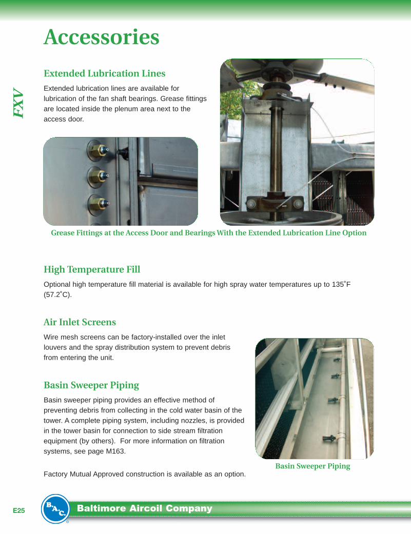
Extended Lubrication Lines
Extended lubrication lines are available forlubrication of the fan shaft bearings. Grease fittingsare located inside the plenum area next to theaccess door.
High Temperature Fill
Optional high temperature fill material is available for high spray water temperatures up to 135˚F(57.2˚C).
Air Inlet Screens
Wire mesh screens can be factory-installed over the inletlouvers and the spray distribution system to prevent debrisfrom entering the unit.
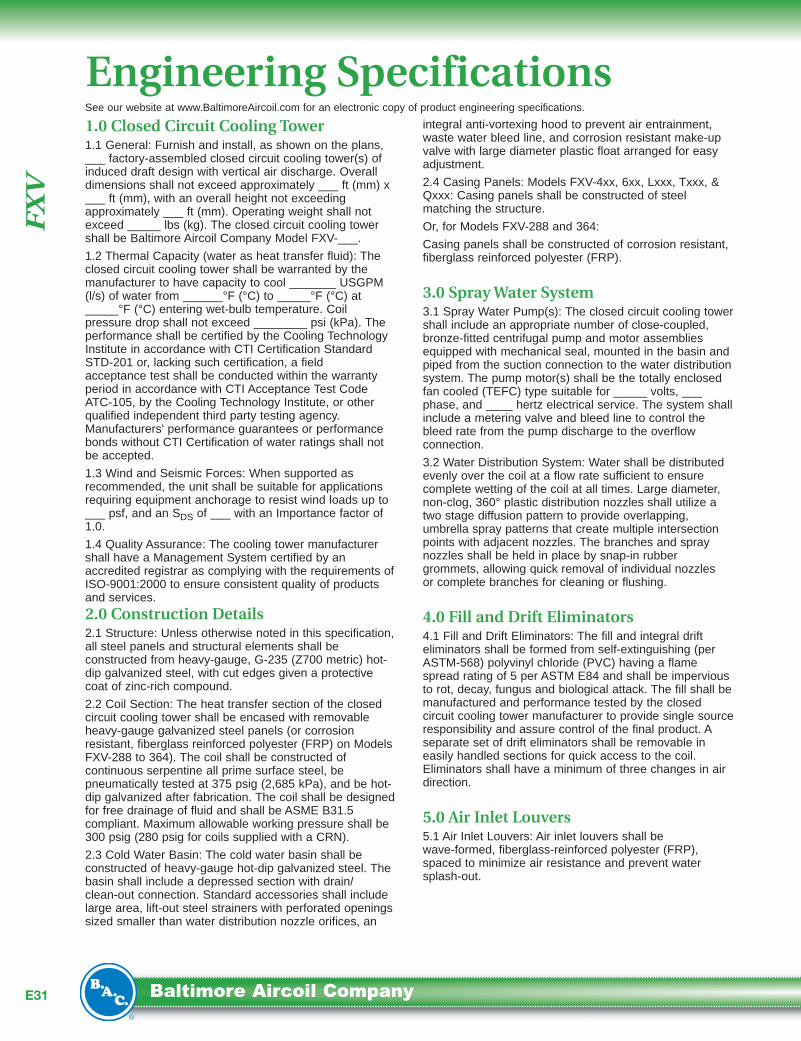
Basin Sweeper Piping
Basin sweeper piping provides an effective method ofpreventing debris from collecting in the cold water basin of thetower. A complete piping system, including nozzles, is providedin the tower basin for connection to side stream filtrationequipment (by others). For more information on filtrationsystems, see page M163.
Factory Mutual Approved construction is available as an option.
Grease Fittings at the Access Door and BearingsWith the Extended Lubrication Line Option
Basin Sweeper Piping

Clo
sedC
ircuit
Co
olin
gT
ow
ers
E26...because temperature matters™
Notes:1. Support steel and anchor bolts to be designed and furnishedby others.
2. All support steel must be level at the top.
3. Beams must be selected in accordance with accepted structuralpractice. Maximum deflection of beam under unit to be 1/360of span, not to exceed 1/2 inch.
4. If vibration isolation rails are to be used between the unit andsupporting steel, be certain to allow for the length of the vibrationrails when determining the length of the supporting steel, asvibration rail length and mounting hole locations may differ fromthose of the unit.
5. If point vibration isolation is used with multi-cell units, the isolatorsmust be located under the support steel, not between the supportsteel and the closed circuit cooling towers.
Single Air Inlet
Dual Air Inlet
The recommended support arrangement for FXV Closed Circuit Cooling Towers consists of parallelI-beams positioned as shown on the drawings. Besides providing adequate support, the steel alsoserves to raise the unit above any solid foundation to assure access to the bottom of the tower.Alternate steel support designs include a cantilevered plan as indicated by the optional minimum “D”dimension in the table below. To support an FXV on columns or in an alternate arrangement not shownhere, consult your local BAC Representative.
Structural Support
Model Number DOptional
Minimum D*MaximumDeflection
FXV - 42x 8’ 3” 5’ 9” 3/16”
FXV - 43x 8’ 3” 5’ 9” 5/16”
FXV - 44x 8’ 3” 5’ 9” 3/8”
FXV - 64x 11’ 7-3/4” 8’ 0” 3/8”
FXV - 66x 11’ 7-3/4” 8’ 0” 1/2”
Model Number DMaximumDeflection
FXV-288-xxx 23’ 9-1/8” 1/2”
FXV-364-xxx 26’ 0-5/8” 1/2”
*When unit is supported with a cantilever plan, the sideopposite the air inlet shall be cantilevered.
AirInlet
AirInlet
AirInlet

FX
V
E27 Baltimore Aircoil Company
Do not use for constructi on. Refer to factory certified dimensions. This handbook includes data currentat the time of publication, which should be reconfirmed at the time of purchase. Up-to-date engineeringdata, free product selection software, and more can be found at www.Balt imoreAirc oil.com .
Engineering Data
Single Air Inlet Models
ModelNumber
NominalTons5
Motor HP Weights (lbs) Dimensions Connection Sizes2,3
SprayPump(GPM)
InternalCoil
Volume(GAL)Fan Pump Operating1 Shipping
HeaviestSection L W H A P
Make-UpWater Coil
FXV-L421 30 5
1.5
7,730 5,050 2,900
6’ 1-1/4” 8’ 5-1/4” 13’ 2-3/4” 6’ 3/4” 1’ 3-3/4” 1-1/2” 4” 190
46FXV-L422 41 5 8,190 5,370 3,220 60FXV-L423 46 5 8,680 5,710 3,560 74FXV-L424 55 7.5 9,160 6,050 3,900 88FXV-421 33 7.5 7,730 5,050 2,900 46FXV-422 46 7.5 8,190 5,370 3,220 60FXV-423 52 7.5 8,680 5,710 3,560 74FXV-424 59 10 9,160 6,050 3,900 88FXV-L431 53 7.5
2
11,230 7,160 4,240
9’ 1-1/4” 8’ 5-1/4” 13’ 2-3/4” 6’ 3/4” 1’ 4-1/4” 1-1/2” 4” 290
69FXV-L432 68 7.5 11,930 7,650 4,730 90FXV-L433 75 7.5 12,630 8,140 5,220 112FXV-L434 86 10 13,380 8,680 5,760 133FXV-431 57 10 11,230 7,160 4,240 69FXV-432 73 10 11,930 7,650 4,730 90FXV-433 81 10 12,630 8,140 5,220 112FXV-434 95 15 13,380 8,680 5,760 133FXV-L441 83 10
3
14,200 8,760 5,120
12’ 1-1/4” 8’ 5-1/4” 13’ 2-3/4” 6’ 3/4” 1’ 8-1/4”
1-1/2” 4”
500
91FXV-L442 100 10 15,150 9,410 5,770 120FXV-L443 110 10 16,080 10,060 6,420 149FXV-L444 130 15 17,070 10,770 7,130 178FXV-441 92 15 14,200 8,760 5,120 91FXV-442 111 15 15,150 9,410 5,770 120FXV-443 122 15 16,080 10,060 6,420 149FXV-444 140 20 17,070 10,770 7,130 178FXV-LQ440 79 10 15,150 9,410 5,770
1-1/2” 6”
124FXV-LQ441 116 15 17,070 10,770 7,130 182FXV-Q440 88 15 15,150 9,410 5,770 124FXV-Q441 125 20 17,070 10,770 7,130 182FXV-L641 126 15
5
18,560 10,890 6,730
12’ 1-1/4” 11’ 10” 15’ 10-3/4” 8’ 8-3/4” 1’ 8-3/4”
1-1/2” 4”
715
146FXV-L642 154 15 20,050 11,930 7,770 192FXV-L643 169 15 21,550 12,980 8,820 238FXV-L644 193 20 23,050 14,040 9,880 284FXV-641 144 25 18,560 10,890 6,730 146FXV-642 175 25 20,050 11,930 7,770 192FXV-643 193 25 21,550 12,980 8,820 238FXV-644 215 30 23,050 14,040 9,880 284FXV-LT642 169 15 21,550 12,980 8,820
1-1/2” 6”
284FXV-T642 192 25 21,650 13,080 8,920 284FXV-LQ640 118 15 20,050 11,930 7,770 194FXV-LQ641 168 20 23,050 14,040 9,880 286FXV-Q640 134 25 20,050 11,930 7,770 194FXV-Q641 186 30 23,050 14,040 9, 880 286FXV-L661 202 22.5
7.5
27,070 15,510 9,690
18’ 1-1/4” 11’ 10” 16’ 4-1/4” 9’ 2-1/4” 2’ 3/8”
1-1/2” 4”
900
218FXV-L662 234 22.5 29,290 17,070 11,250 288FXV-L663 257 22.5 31,570 18,670 12,850 358FXV-L664 297 30 33,810 20,280 14,460 429FXV-661 231 40 27,070 15,510 9,690 218FXV-662 267 40 29,290 17,070 11,250 288FXV-663 295 40 31,570 18,670 12,850 358FXV-664 331 45 33,810 20,280 14,460 429FXV-LT662 263 22.5 33,790 20,260 14,440
1-1/2” 8”
429FXV-T662 297 40 33,810 20,280 14,460 429FXV-LQ660 189 22.5 29,290 17,070 11,250 299FXV-LQ661 269 30 33,810 20,280 14,460 439FXV-Q660 215 40 29,290 17,070 11,250 299FXV-Q661 299 45 33,810 20,280 14,460 439

Clo
sedC
ircuit
Co
olin
gT
ow
ers
E28...because temperature matters™
Dual Air Inlet Models
Notes:1. Operating weight is for the tower with the water level in the coldwater basin at the overflow.
2. The actual size of the inlet and outlet connection may vary withthe design flow rate. Consult unit print for dimensions.
3. Inlet and outlet connections are beveled for welding.
4. Standard make-up, drain and overflow connections are locatedon the bottom of the unit. Make-up connection is 1-1/2” MPTstandpipe, drain is 2” FPT and overflow is 3” FPT. On single air-inlet models, standard make-up, drain and overflow connectionsare MPT.
5. Models shipped with an optional gear drive or low sound fanmay have heights up to 10.5" greater than shown. Models withWhisper Quiet Fans may have heights up to 5-1/2” greater thanshown.
6. Nominal tons of cooling represents the capability to cool 3 GPM ofwater from a 95ºF entering water temperature to an 85ºF leavingwater temperature at a 78ºF entering wet-bulb temperature.
7. For FXV-44xx, the riser pipe diameter is 4”. For FXV-6xx and alldual air inlet models, the riser pipe is 6”.
See page E77for Engineerin gConsi deratio ns.
Model NumberNominalTons6
Motor HP Weights (lbs) DimensionsSprayPump(GPM)
Internal CoilVolume(GAL)Fan Pump Operating1 Shipping
HeaviestSection L W H
FXV-288-31M 344 20
15
46,000 27,680 8,050
11’ 11” 24’ 1/2” 18’ 10-3/8” 1,720
600FXV-288-31N 367 25 46,030 27,710 8,050 600FXV-288-31O 386 30 46,080 27,760 8,050 600FXV-288-31P 419 40 46,240 27,920 8,050 600FXV-288-31Q 445 50 46,250 27,930 8,050 600FXV-288-31R 468 60 46,465 28,145 8,050 600FXV-288-41M 364 20 49,690 30,440 9,430 712FXV-288-41N 389 25 49,720 30,470 9,430 712FXV-288-41O 412 30 49,770 30,520 9,430 712FXV-288-41P 448 40 49,930 30,680 9,430 712FXV-288-41Q 478 50 49,940 30,690 9,430 712FXV-288-41R 502 60 50,155 30,905 9,430 712FXV-288-2TM 349 20 49,690 30,440 9,430 712FXV-288-2TN 372 25 49,720 30,470 9,430 712FXV-288-2TO 392 30 49,770 30,520 9,430 712FXV-288-2TP 424 40 49,930 30,680 9,430 712FXV-288-2TQ 449 50 49,940 30,690 9,430 712FXV-288-2TR 470 60 50,155 30,905 9,430 712FXV-288-1QM 325 20 49,690 30,440 9,430 706FXV-288-1QN 347 25 49,720 30,470 9,430 706FXV-288-1QO 365 30 49,770 30,520 9,430 706FXV-288-1QP 394 40 49,930 30,680 9,430 706FXV-288-1QQ 418 50 49,940 30,690 9,430 706FXV-288-1QR 439 60 50,160 30,910 9,430 706FXV-364-31N 442 25
15
53,900 31,630 9,390
13’ 11-1/8” 26’ 3-1/2” 19’ 0-3/8” 1,720
696FXV-364-31O 463 30 53,950 31,680 9,390 696FXV-364-31P 496 40 54,110 31,840 9,390 696FXV-364-31Q 525 50 54,120 31,850 9,390 696FXV-364-31R 550 60 54,335 32,065 9,390 696FXV-364-31S 579 75 54,435 32,165 9,390 696FXV-364-41N 464 25 58,260 34,910 11,030 828FXV-364-41O 489 30 58,310 34,960 11,030 828FXV-364-41P 530 40 58,470 35,120 11,030 828FXV-364-41Q 561 50 58,480 35,130 11,030 828FXV-364-41R 589 60 58,695 35,345 11,030 828FXV-364-41S 624 75 58,795 35,445 11,030 828FXV-364-2TN 443 25 58,260 34,910 11,030 828FXV-364-2TO 463 30 58,310 34,960 11,030 828FXV-364-2TP 498 40 58,470 35,120 11,030 828FXV-364-2TQ 526 50 58,480 35,130 11,030 828FXV-364-2TR 549 60 58,695 35,345 11,030 828FXV-364-2TS 574 75 58,795 35,445 11,030 828FXV-364-1QN 420 25 58,260 34,910 11,030 862FXV-364-1QO 442 30 58,310 34,960 11,030 862FXV-364-1QP 472 40 58,470 35,120 11,030 862FXV-364-1QQ 499 50 58,480 35,130 11,030 862FXV-364-1QR 522 60 58,700 35,350 11,030 862FXV-364-1QS 550 70 58,800 35,450 11,030 862

FX
V
E29 Baltimore Aircoil Company
3" OVERFLOW
2" DRAIN
Single Air Inlet Models
Dual Air Inlet Models
6" FLUID OUT
6" FLUID IN

Clo
sedC
ircuit
Co
olin
gT
ow
ers
E30...because temperature matters™
Engineering Data:ColdWeather Operation
Notes:1 Heat loss based on 50ºF entering coil water and -10ºF ambientwith 45 MPH wind (fans and pump off).
2. One inch thick PVC nitrite rubber blend thermal insulation on boththe PCD hood and the casing panels surrounding the coil.
Notes:1. Hood shipping weightincludes shipping skidweight.
FXV Heat Loss Data (BTUH)
Dimensional Data of Positive Closure Damper Hood
ModelNumber
StandardUnit
Unit w/PCD Hood
Unit w/ PCDHood & Insulation
FXV-421FXV-422FXV-423FXV-424
68,40087,100105,200122,400
43,50047,10050,50054,000
30,10032,30034,70037,000
FXV-431FXV-432FXV-433FXV-434
102,800131,200158,000183,000
60,80065,60070,60074,900
43,20046,50049,60052,800
FXV-441FXV-442FXV-443FXV-444FXV-Q440FXV-Q441
135,700172,900208,000241,000172,900241,000
76,70082,10087,60092,90082,10092,900
55,20059,10062,90066,50059,10066,500
FXV-641FXV-642FXV-643FXV-644FXV-T642FXV-Q640FXV-Q641
203,400259,800313,100362,900362,900259,800362,900
103,800109,700115,600121,300121,300109,700121,300
75,30079,30083,20086,90086,90079,30086,900
FXV-661FXV-662FXV-663FXV-664FXV-T662FXV-Q660FXV-Q661
304,500387,500404,700536,900536,900387,500536,900
158,200165,500172,400179,100179,100165,500179,100
118,000123,000127,600132,200132,200123,000132,200
FXV-288-31xFXV-288-41xFXV-288-2TXFXV-288-1Qx
760,200881,100881,100881,100
280,700294,500294,500294,500
202,000211,000211,000211,000
FXV-364-31xFXV-364-41xFXV-364-2TXFXV-364-1Qx
894,0001,036,2001,036,2001,036,200
330,100346,400346,400346,400
237,600248,100248,100248,100
ModelNumber
Hood Ship.Weight (lbs.)
Operating Weight Add(lbs.)
Length(L) Width (W)
Hood Height(Y)
Unit Height(H)
FXV-42x 390 320 5’ 11-7/8” 3’ 5-1/4” 2’ 5-1/8” 15’ 1-3/4”
FXV-43x 540 430 8’ 11-7/8” 3’ 5-1/4” 2’ 5-1/8” 15’ 1-3/4”
FXV-44x 720 570 11’ 11-7/8” 3’ 5-1/4” 2’ 5-1/8” 15’ 1-3/4”
FXV-64x 1,160 920 11’ 11-7/8” 5’ 3-1/2” 2’ 5-1/8” 17’ 9-3/4”
FXV-66x 1,650 1,300 17’ 11-7/8” 5’ 3-1/2” 2’ 5-1/8” 17’ 9-3/4”
FXV-288-xxx 1,300 1,040 11’ 11” 6’ 3-3/8” 2’ 5-1/8” 20’ 2-5/8”
FXV-364-xxx 1,500 1,200 13’ 11-1/8” 6’ 3-3/8” 2’ 5-1/8” 20’ 2-5/8”
FX
V
E31 Baltimore Aircoil Company
1.0 Closed Circuit Cooling Tower1.1 General: Furnish and install, as shown on the plans,___ factory-assembled closed circuit cooling tower(s) ofinduced draft design with vertical air discharge. Overalldimensions shall not exceed approximately ___ ft (mm) x___ ft (mm), with an overall height not exceedingapproximately ___ ft (mm). Operating weight shall notexceed _____ lbs (kg). The closed circuit cooling towershall be Baltimore Aircoil Company Model FXV-___.
1.2 Thermal Capacity (water as heat transfer fluid): Theclosed circuit cooling tower shall be warranted by themanufacturer to have capacity to cool _______ USGPM(l/s) of water from ______°F (°C) to _____°F (°C) at_____°F (°C) entering wet-bulb temperature. Coilpressure drop shall not exceed ________ psi (kPa). Theperformance shall be certified by the Cooling TechnologyInstitute in accordance with CTI Certification StandardSTD-201 or, lacking such certification, a fieldacceptance test shall be conducted within the warrantyperiod in accordance with CTI Acceptance Test CodeATC-105, by the Cooling Technology Institute, or otherqualified independent third party testing agency.Manufacturers' performance guarantees or performancebonds without CTI Certification of water ratings shall notbe accepted.
1.3 Wind and Seismic Forces: When supported asrecommended, the unit shall be suitable for applicationsrequiring equipment anchorage to resist wind loads up to___ psf, and an SDS of ___ with an Importance factor of1.0.
1.4 Quality Assurance: The cooling tower manufacturershall have a Management System certified by anaccredited registrar as complying with the requirements ofISO-9001:2000 to ensure consistent quality of productsand services.
2.0 Construction Details2.1 Structure: Unless otherwise noted in this specification,all steel panels and structural elements shall beconstructed from heavy-gauge, G-235 (Z700 metric) hot-dip galvanized steel, with cut edges given a protectivecoat of zinc-rich compound.
2.2 Coil Section: The heat transfer section of the closedcircuit cooling tower shall be encased with removableheavy-gauge galvanized steel panels (or corrosionresistant, fiberglass reinforced polyester (FRP) on ModelsFXV-288 to 364). The coil shall be constructed ofcontinuous serpentine all prime surface steel, bepneumatically tested at 375 psig (2,685 kPa), and be hot-dip galvanized after fabrication. The coil shall be designedfor free drainage of fluid and shall be ASME B31.5compliant. Maximum allowable working pressure shall be300 psig (280 psig for coils supplied with a CRN).
2.3 Cold Water Basin: The cold water basin shall beconstructed of heavy-gauge hot-dip galvanized steel. Thebasin shall include a depressed section with drain/clean-out connection. Standard accessories shall includelarge area, lift-out steel strainers with perforated openingssized smaller than water distribution nozzle orifices, an
integral anti-vortexing hood to prevent air entrainment,waste water bleed line, and corrosion resistant make-upvalve with large diameter plastic float arranged for easyadjustment.
2.4 Casing Panels: Models FXV-4xx, 6xx, Lxxx, Txxx, &Qxxx: Casing panels shall be constructed of steelmatching the structure.
Or, for Models FXV-288 and 364:
Casing panels shall be constructed of corrosion resistant,fiberglass reinforced polyester (FRP).
3.0 SprayWater System3.1 Spray Water Pump(s): The closed circuit cooling towershall include an appropriate number of close-coupled,bronze-fitted centrifugal pump and motor assembliesequipped with mechanical seal, mounted in the basin andpiped from the suction connection to the water distributionsystem. The pump motor(s) shall be the totally enclosedfan cooled (TEFC) type suitable for _____ volts, ___phase, and ____ hertz electrical service. The system shallinclude a metering valve and bleed line to control thebleed rate from the pump discharge to the overflowconnection.
3.2 Water Distribution System: Water shall be distributedevenly over the coil at a flow rate sufficient to ensurecomplete wetting of the coil at all times. Large diameter,non-clog, 360° plastic distribution nozzles shall utilize atwo stage diffusion pattern to provide overlapping,umbrella spray patterns that create multiple intersectionpoints with adjacent nozzles. The branches and spraynozzles shall be held in place by snap-in rubbergrommets, allowing quick removal of individual nozzlesor complete branches for cleaning or flushing.
4.0 Fill and Drift Eliminators4.1 Fill and Drift Eliminators: The fill and integral drifteliminators shall be formed from self-extinguishing (perASTM-568) polyvinyl chloride (PVC) having a flamespread rating of 5 per ASTM E84 and shall be imperviousto rot, decay, fungus and biological attack. The fill shall bemanufactured and performance tested by the closedcircuit cooling tower manufacturer to provide single sourceresponsibility and assure control of the final product. Aseparate set of drift eliminators shall be removable ineasily handled sections for quick access to the coil.Eliminators shall have a minimum of three changes in airdirection.
5.0 Air Inlet Louvers5.1 Air Inlet Louvers: Air inlet louvers shall bewave-formed, fiberglass-reinforced polyester (FRP),spaced to minimize air resistance and prevent watersplash-out.
Engineering SpecificationsSee our website at www.BaltimoreAircoil.com for an electronic copy of product engineering specifications.

Clo
sedC
ircuit
Co
olin
gT
ow
ers
E32...because temperature matters™
6.0 Mechanical Equipment6.1 Fan(s): Fan(s) shall be heavy-duty, axial flow, withaluminum alloy blades. Air shall discharge through a fancylinder designed for streamlined air entry and minimumfan blade tip clearance for maximum fan efficiency. Fan(s)and shaft(s) shall be supported by heavy-duty, self-aligning, grease-packed ball bearings with moisture-proofseals and integral slinger rings, designed for minimum L10life of 40,000 hours. Fan(s) shall be drive by a one-piece,multi-groove neoprene/polyester belt designed specificallyfor evaporative cooling service. Fan and motor sheave(s)shall be fabricated from cast aluminum.
6.2 Fan Motor: Fan motor(s) shall be totally enclosedreversible, squirrel cage, ball bearing type designedspecifically for evaporative cooling duty on ____ volt/ ___hertz/ ____ phase electrical service. The motor shall befurnished with special moisture protection on windings,shafts, and bearings. Fan motors shall be premiumefficient/inverter duty type designed per NEMA StandardMG1, Section IV, Part 31.
6.3 Mechanical Equipment Warranty: The fan(s), fanshaft(s), sheaves, bearings, mechanical equipmentsupport and fan motor shall be warranted against defectsin materials and workmanship for a period of five (5)years from date of shipment.
7.0 Access7.1 Plenum Access: A large, hinged access door shall beprovided on each end wall for access to the coil, drifteliminators, and fan plenum section. The water make-upvalve, float ball, and suction strainer shall be easilyaccessible. On single side air inlet units, the access doorshall open to an internal walkway.
8.0 Sound8.1 Sound Level: To maintain the quality of the localenvironment, the maximum sound pressure levels (dB)measured 50 ft (15,240 mm) from the closed circuitcooling tower operating at full fan speed shall not exceedthe sound levels detailed below.
9.0 Accessories9.1 Basin Heater(s): The cooling tower cold water basinshall be provided with electric heater(s) to preventfreezing in low ambient conditions. The heater(s) shall beselected to maintain 40°F (4.4˚C) pan water temperaturesat ____° F(˚C) ambient. The heater(s) shall be______V/____ phase/___Hz electric and shall be provided with lowwater cutout and thermostat.
9.2 Vibration Cutout Switch: Provide mechanical localreset vibration switch. The mechanical vibration cutoutswitch will be guaranteed to trip at a point so as not to
cause damage to the cooling tower. To ensure this, thetrip point will be a frequency range of 0 to 3,600 RPMand a trip point of 0.2 to 2.0 g’s.
9.3 Heat loss: The heat loss for the FXV shall be equalto or less than __________ BTUH using either astandard unit, a unit with a hood, positive closuredampers, insulation or a combination.
Loc ation 63 125 250 500 1000 2000 4000 8000 dB(A)
Discharge
Air Inlet
Cased Face

E33 Baltimore Aircoil Company
Pro
du
ctR
epo
rt
The BAC 360™ Spray Nozzle
Standard on BAC CoilProducts:FXV,VFL,VF1, CXV, CXV-T,VC1,VCA, andVCLReduce maintenance costs and ensure efficientequipment operation with BAC’s latest non-clognozzle that combines scatter diffusion technologywith BAC’s largest nozzle orifice yet, to create themost technologically advanced spray nozzle in theindustry!
The nozzles are designed in concert with BACspray distribution systems to optimize theperformance of your BAC equipment. Thesenozzles are an easy retrofit for many units fromother manufacturers too! Contact BAC forcompetitive cross reference assistance.
Spray patterns overlap,eliminating dryspots on the coils
No alignment needed
2 stagediffusion cones
Large orifice,360o spray
Water in
Features and Benefits
• Ease of Maintenance- Easy snap in/out grommet design- Large non-clog orifice
• Robust, durable construction
• Universal alignment
• Anti-scale design
• No moving parts
• Eliminates dry spots inherent in otherdesigns
A complete list of BAC Representatives is available atwww.BaltimoreAircoil.com. Call yours and ask to see aBAC 360™ Spray Nozzle today!