Ba2503 3703us4 3 - Allwest · PDF fileThe model 2503/3003/3503/3703 excavators are...
21
Track Excavator 2503, 3003 3503, 3703 OPERATOR’S MANUAL 1000183730 4.3 0309 1 0 0 0 1 8 3 7 3 0
Transcript of Ba2503 3703us4 3 - Allwest · PDF fileThe model 2503/3003/3503/3703 excavators are...

Track Excavator
2503, 30033503, 3703
OPERATOR’S MANUAL
1000183730 4.3
0309
1 0 0 0 1 8 3 7 3 0

OM 25-3703 US – Edition 4.2 * 2503_3703b110.fm 1-1
Introduction
1 Introduction1.1 Important operator information
Store the Operator's Manual in the storage compartment at the rear of the seat.This Operator's Manual contains important information on how to work safely, correctly and economically with the machine. It provides information and instruction for all operators regardless of experience. It helps to avoid dangerous situations and reduce repair costs and downtimes. Furthermore, the reliability and the service life of the machine will be increased by following the instructions in the Operator's Manual. This is why the Operator's Manual must always be kept at hand in the machine.Your own safety, as well as the safety of others, depends to a great extent on how the machine is moved and operated. Thoroughly read and understand the information in this Operator's Manual before operating the machine for the first time. This Operator's Manual will help to familiarize yourself more easily with the machine, thereby enabling you to use it more safely and efficiently.Before operating this machine for the first time, carefully read the section "Safety Instruc-tions" to learn how to operate the machine safely. As a rule, keep the following in mind:Careful and prudent working is the best way to avoid accidents!Special Instructions• Instructions are provided for bucket attachments. No instructions are provided for other
attachments. Refer to the specific attachment operator's manual for safe operation.• Wacker Neuson reserves the right to make product improvement changes during the
course of series production of this machine.• Modifying the manufacturer specification and configuration of this machine, or using
unapproved attachments, can cause personal hazards and damage the machine. Contact your Wacker Neuson dealer for additional information and clarification regarding modifications.
Operational safety and readiness of the machine do not only depend on your skill, but also on maintenance and servicing of the machine. This is why regular maintenance and ser-vice work is absolutely necessary. Extensive maintenance and repair work must always be performed by an expert with appropriate training. Insist on using original spare parts when performing maintenance and repair work. This ensures operational safety and readiness of your machine, and maintains its value.• Special equipment and superstructures are not described in this Operator's Manual.• We reserve the right to improve the technical standard of our machines.• Modifying Wacker Neuson products and fitting them with additional equipment and
tools not included in our delivery program requires Wacker Neuson's written authori-zation, otherwise warranty and product liability for possible damage caused by these modifications shall not be applicable.
Your Wacker Neuson dealer will be pleased to answer any further questions regarding the machine or the Operator's Manual.Abbreviations/symbols • This symbol stands for a list.
• Subdivision within lists or an activity. Follow the steps in the recommended sequence.
☞This symbol requires you to perform the activity described.This symbol requires you to perform the activity described.
➥Description of the effects or results of an activity.n. s. = not shown “Opt” = option Stated whenever controls or other components of the machine are installed as an option.
This symbol shows the driving direction – for better orientation in figures and graphics.

1-2 OM 25-3703 US – Edition 4.2 * * 2503_3703b110.fm
Introduction
1.2 Machine overview
1 Boom light2 Boom3 Stick4 Rubber tracks5 Undercarriage6 Stabilizer blade7 Cab8 Valve cover9 Handle
Fig. 1: Machine outside views
6
9
14
13
13
15
8
7
1
14
13 Muffler pipe
14 Lifting and tie down point15 Lubrication point for track tension16 Engine cover
2
3
4
5
5
7
16

OM 25-3703 US – Edition 4.2 * 2503_3703b110.fm 1-3
Introduction
1.3 Brief descriptionThe model 2503/3003/3503/3703 excavators are self-propelled work machines.Get informed on and follow the legal regulations of your country.This machine is a versatile and powerful tool for moving earth, gravel and debris onconstruction sites and elsewhere. A wide range of attachments accounts for the numerous applications of the machine, among others hammer and grab applications. See chapter Chapter “Fields of application, attachments” on page 1-4.The main components of the machine are:• FOPS (Falling Object Protective Structure), TOPS (Tip Over Protective Structure) and
ROPS (Roll Over Protected Strucute) tested closed cab (standard)• FOPS (Falling Object Protective Structure), TOPS (Tip Over Protective Structure) and
ROPS (Roll Over Protected Strucute) tested open cab (option)• Water-cooled Yanmar four cylinder diesel engine • Sturdy steel sheet chassis; rubber-mounted engine
Travelling driveThe diesel engine permanently drives the twin axial variable displacement pump whose oil flow is sent to a hydraulic motor for each track drive.
Work hydraulics The diesel engine also drives the joint gear pump for the work hydraulics. The oil flow of this pump depends on the diesel engine speed only.
Cooling systemCoolant temperature is monitored on the machine's instrument panel.
CabDo not modify or attempt to repair the ROPS cab or ROPS structure. A bent or damaged ROPS will no longer protect the operator in the event of a tipping incident and must be replaced. Contact your Wacker Neuson dealer for instructions or clarification. The ROPS is a special safety device designed and produced to exacting material and assembly standards for certification. Bending, heating, welding, cutting, or drilling holes in the ROPS will reduce the protection performance in a tipping incident.Fasten your seatbelt, otherwise you can be thrown around or even outside the cab and crushed. Therefore always fasten your seatbelt as you drive and work with the machine. Tighten the seatbelt before taking up work with the machine.

1-4 OM 25-3703 US – Edition 4.2 * * 2503_3703b110.fm
Introduction
1.4 Fields of application, attachmentsThe attachments installed determine the intended use of this machine.
NOTICEIn order to avoid damage to the machine, only the attachments listed below have been certified for installation on the machine.
Contact your Wacker Neuson dealer if you wish to use other attachments.
Using tools of other manufacturers, or tools which have been released for other excavator types, can reduce the machine's output and stability considerably, and can also cause damage to the machine and injuries to the operator or the staff.Always compare the weight of the tool and its maximum payload with the indications in the lift capacity table. Never exceed the maximum payload stated in the lift capacity table.
Use: attachmentThe measurements are Metric (Imperial).Possible attachments
Description of attachment Capacity Item no.: Excavator Remarks
Complete quickhitch- 1000004049 2503 Required for operation of
WackerNeuson quickhitch systems- 1000018479 3503
Bucket B=260 mm (10.2’’)36 l (1.3 ft3) 1000093539 2503
36 l (1.3 ft3) 1000093543 2503 For quickhitch
Bucket B=300 mm (11.8’’)
43 l (1.5 ft3) 1000093534 2503
43 l (1.5 ft3) 1000017122 2503 For quickhitch
50 l (1.8 ft3) 1000093755 3503
50 l (1.8 ft3) 1000017130 3503 For quickhitch
Bucket B=400 mm (1’4’’)
59 l (2.1 ft3) 1000093536 2503
59 l (2.1 ft3) 1000093542 2503 For quickhitch
69 l (2.4 ft3) 1000093756 3503
69 l (2.4 ft3) 1000017125 3503 For quickhitch
Bucket B=500 mm (1’8’’)
75 l (2.6 ft3) 1000093535 2503
75 l (2.6 ft3) 1000093541 2503 For quickhitch
88 l (3.1 ft3) 1000093757 3503
88 l (3.1 ft3) 1000017127 3503 For quickhitch

OM 25-3703 US – Edition 4.2 * 2503_3703b110.fm 1-5
Introduction
Bucket B=600 mm (2’)
91 l (3.2 ft3) 1000093537 2503
91 l (3.2 ft3) 1000017121 2503 For quickhitch
107 l (3.8 ft3) 1000093758 3503
107 l (3.8 ft3) 1000017134 3503 For quickhitch
Bucket B=700 mm (2’4’’)
107 l (3.8 ft3) 1000093538 2503
107 l (3.8 ft3) 1000093540 2503 For quickhitch
127 l (4.5 ft3) 1000093759 3503
127 l (4.5 ft3) 1000017128 3503 For quickhitch
Offset bucket B=850 mm (2’9’’) short stick73 l (2.6 ft3) 1000093462 2503
73 l (2.6 ft3) 1000017105 2503 For quickhitch
Offset bucket B=1000 mm (3’4’’) short stick
87 l (3.1 ft3) 1000096529 2503
87 l (3.1 ft3) 1000017106 2503 For quickhitch
111 l (3.9 ft3) 1000096567 3503
111 l (3.9 ft3) 1000017131 3503 For quickhitch
Offset bucket B=1400 mm (4’7’’) short stick158 l (5.6 ft3) 1000096568 3503
158 l (5.6 ft3) 1000017132 3503 For quickhitch
Offset bucket B=850 mm (2’9’’) long stick73 l (2.6 ft3) 1000093546 2503
73 l (2.6 ft3) 1000093548 2503 For quickhitch
Offset bucket B=1000 mm (3’4’’) long stick
87 l (3.1 ft3) 1000096541 2503
87 l (3.1 ft3) 1000096542 2503 For quickhitch
111 l (3.9 ft3) 1000096569 3503
111 l (3.9 ft3) 1000096571 3503 For quickhitch
Offset bucket B=1400 mm (4’7’’) long stick158 l (5.6 ft3) 1000096570 3503
158 l (5.6 ft3) 1000096572 3503 For quickhitch
Grabenräumlöffel B=850 (2’9’’) mm69 l (2.4 ft3) 1000093460 2503
69 l (2.4 ft3) 1000093335 2503 For quickhitch
Ditch cleaning Bucket B=1000 mm (3’4’’)82 l (2.9 ft3) 1000096528 2503
82 l (2.9 ft3) 1000096518 2503 For quickhitch
Description of attachment Capacity Item no.: Excavator Remarks

1-6 OM 25-3703 US – Edition 4.2 * * 2503_3703b110.fm
Introduction
1.5 Operator QualificationsRequirements to be met by the driverEarth moving machines may be driven and serviced only by persons who meet thefollowing requirements:• 18 years or older• Physically and mentally suited for this work• Persons have been instructed in driving and servicing the earth moving machine and
have proven their qualifications to the contractor• Persons are expected to perform work reliably.They have been appointed by the contractor for driving and servicing the earth moving machine.Get informed on and follow the legal regulations of your country.
Ditch cleaning Bucket B=1000 mm (3’4’’)117 l (4.1 ft3) 1000096563 3503
116 l (4.1 ft3) 1000096549 3503 For quickhitch
Ditch cleaning Bucket B=1200 mm (3’11’’)98 l (3.5 ft3) 1000096540 2503
98 l (3.5 ft3) 1000096539 2503 For quickhitch
Ditch cleaning Bucket B=1400 mm (4’7’’)166 l (5.9 ft3) 1000096564 3503
164 l (5.8 ft3) 1000096550 3503 For quickhitch
Hammer mount console- 1000020344 2503
- 1000070743 3503
Description of attachment Capacity Item no.: Excavator Remarks

OM 25-3703 US – Edition 4.2 * 2503_3703b110.fm 1-7
Introduction
1.6 EC declaration of conformity (Kubota engine)EC Declaration of Conformity
According to Machine Directive 98/37/EC, appendix II A
Wacker Neuson Linz GmbHHaidfeldstr. 37
A-4060 Linz-Leondingcertifies that the construction machine
Type Track excavatorMake Wacker NeusonModels 2503/3703Number within the machine's series - - - - - - - - - - -
corresponds to the following pertinent guidelines98/37/EC89/336/EC00/14/EC
Applied harmonised standardsEN 292-1:1991, EN 292-2:1995EN 474-1:1994, EN 474-5:1996EN 982:1996
National standards and technical specifications
Inspection body involved (German Industrial Supervisory Board for Technical Facilities and Environmental Issues)TÜV Anlagen und Umwelt GmbH
Westendstr. 199D-80686 Munich
The registered body according to appendix VIITechnical construction engineering committeeLandsberger Str. 309D-80687 Munich
has been consulted for a voluntary design test Type-examination certificate no.: 00198-E
00199-E00200-E00201-E
Linz-Leonding, (date) _ _ . _ _ . _ _ _ _
Josef ErlingerWacker Neuson Linz GmbH
Type Measured sound power level Guaranteed sound power level
Certificate no.:
2503 92.7 94.0 OR/01513/013003 95.1 96.0 OR/01514/013503 95.5 97.0 OR/01515/013703 95.5 97.0 OR/01515/01

1-8 OM 25-3703 US – Edition 4.2 * * 2503_3703b110.fm
Introduction
1.7 EC declaration of conformity (Yanmar engine up to serial number AG00579) EC Declaration of Conformity
According to Machine Directive 98/37/EC, appendix II A
Wacker Neuson Linz GmbHHaidfeldstr. 37
A-4060 Linz-Leondingcertifies that the construction machine
Type Track excavatorMake Wacker NeusonModels 2503/3703Number within the machine's series - - - - - - - - - - -
corresponds to the following pertinent guidelines98/37/EC89/336/EC00/14/EC
Applied harmonised standardsEN 292-1:1991, EN 292-2:1995EN 474-1:1994, EN 474-5:1996EN 982:1996
National standards and technical specifications
Inspection body involved (German Industrial Supervisory Board for Technical Facilities and Environmental Issues)TÜV Anlagen und Umwelt GmbH
Westendstr. 199D-80686 Munich
The registered body according to appendix VIITechnical construction engineering committeeLandsberger Str. 309D-80687 Munich
has been consulted for a voluntary design test Type-examination certificate no.: 00198-E
00199-E00200-E00201-E
Linz-Leonding, (date) _ _ . _ _ . _ _ _ _
Josef ErlingerWacker Neuson Linz GmbH
Type Measured sound power level Guaranteed sound power level
Certificate no.:
2503 94.2 94.0 OR/015903003 95.3 95.0 OR/015913503 95.4 95.0 OR/015923703 95.4 95.0 OR/01592

OM 25-3703 US – Edition 4.2 * 2503_3703b110.fm 1-9
Introduction
1.8 EC declaration of conformity (Yanmar engine from serial number AG00580)
EC Declaration of Conformityaccording to EC Directive 98/37/EC, 2000/14/EC Appendix 6
Wacker Neuson Linz GmbHHaidfeldstr. 37
A-4060 Linz-Leonding
declare, under their own responsibility, that the product
Product name Wacker Neuson track excavators 25-3703Models 25-3703Versions 25-3703Serial no. - - - - - - - - - - -
to which this declaration refers, corresponds to the pertinent fundamental requirements regarding safety and health of
EC Directive 98/37/EC,and the requirements of further pertinent EC Directives and standards.
The following standards and/or technical specifications have been used for the proper application of the requirements regarding safety and health stated in the EC Directives:EN 474-1, EN 474-3, EN292-1, EN 292-2, ISO 3471, EN 13510;
Place of storage of technical documentation:Wacker Neuson Linz GmbHDepartment: R & DHaidfeldstr. 37A-4060 Linz-Leonding
Linz-Leonding, (date) _ _ . _ _ . _ _ _ _
Josef ErlingerWacker Neuson Linz GmbH
ISO 3471 and EN 13510
Tested Administrative unit reported according to Appendix 6
2000/14/EC
information Noise level dBA
TÜV München(Munich/Germany Industrial Supervisory Board) Westendstr. 199D-80686 Munich
Measured value
Guaranteed value

1-10 OM 25-3703 US – Edition 4.2 * * 2503_3703b110.fm
Introduction
1.9 Type labels and component numbersSerial number AG00580The serial number is stamped on the machine chassis. It is also located on the Product Identification Number plate riveted to the front left chassis of the machine.Type label informationExample: 3703
Model: 3703Year: 2007PIN: AG00580Power, SAE: 23.7 kW (31.8 hp)Mass: 3726 kg (8214 lbs)Load: ---------------Max. gross mass: ---------------Max. axle load: ---------------
---------------Other information – see chapter 6 Specifications on page 6-1
Cab certification numberThe certification label (arrow) is located on the chassis of the cab, at the upper left beside the door.
Fig. 1: Type label: location
Fig. 2: Type label
Fig. 3: Cab type label

OM 25-3703 US – Edition 4.2 * 2503_3703b110.fm 1-11
Introduction
Engine serial numberThe type label (arrow) is located on the cylinder-head cover (engine).
Example: Yanmar 46557
Fig. 4: Diesel engine type label from serial number AG00580
Fig. 4: Diesel engine type label up to serial number AG00579

1-12 OM 25-3703 US – Edition 4.2 * * 2503_3703b110.fm
Introduction
Label overview

OM 25-3703 US – Edition 4.2 * 2503_3703b110.fm 1-13
Introduction
1.10 SymbolsThe following symbols are displayed on the machine to provide pictorial information to the user. The information and explanations are provided to avoid misinterpretation by the user. The symbols have been chosen to provide important information to those involved with operating, adjusting, maintaining, and repairing this machine.
DescriptionLocates the lifting points for hoisting the excavator with lifting devices (slings, tracks, or cables).LocationOn either side of the stabilizer blade, and on either side of the boom near the cylinder end of the stick hydraulic cylinder mounting.
DescriptionTie down points.Location points designated for tie down of the machine during transport to prevent movement during transport. LocationOn either side of the stabilizer blade, and on either side of the undercarriage.
DescriptionNoise levels produced by the machine.LWA = sound power levelLocationCabin: On left window.Canopy: On the left side of the seat console.
DescriptionThis label shows the forward driving direction.LocationOn each undercarriage at the idler end of the structure.
DescriptionFill location for diesel fuel only.LocationOn the fuel filler neck in engine room.
Fig. 5: Eye hook label
Fig. 6: Label for points used for strapping down the machine
Fig. 7: Noise level label
Fig. 8: Direction arrows
Fig. 9: Diesel

1-14 OM 25-3703 US – Edition 4.2 * * 2503_3703b110.fm
Introduction
DescriptionHydraulic oil reservoir. Use hydraulic fluid only.LocationOn the hydraulic oil reservoir.
DescriptionIndicate the cable control to open the engine cover. LocationOn the front side of the seat console.
DescriptionIndicate the cable control to open the valve cover. LocationOn the front side of the seat console.
DescriptionExplains the functions of the joysticks (control pattern "A") and of other controls. If the machine is fitted with the "selection valve" check before starting the machine which control pattern you have chosen!LocationOn the cabin roof.
DescriptionExplains the position of the ball valve for different attachments.LocationOn the hydraulic oil tank.
DescriptionShows the interval for greasing. LocationOn the front of the upper carriage.
Fig. 10: Hydraulic oil
Fig. 11: Cable control engine hot
Fig. 12: Cable control valve cover
Fig. 13: Functions of joysticks
Fig. 14: Position of the ball valve
Fig. 15: Interval for greasing

OM 25-3703 US – Edition 4.2 * 2503_3703b110.fm 1-15
Introduction
Description (Opt.)Explains the functions of the joysticks (control pattern "B"). Check before starting the machine which control pattern you have chosen!LocationOn the cab roof.
Safety Labels Always follow the instructions on the safety labels!
DescriptionThe label means the following:• Potential high pressure grease discharge from the track tension adjustment fitting.• Read the Operator’s Manual before releasing or tightening the tracks to avoid potential
injury from ejected grease.LocationOn the undercarriage near the opening or dismounting to insert the grease fitting.
DescriptionStop the engine before opening the safety devices ( like engine hoot, fan guard,..)LocationOn the engine hood.
DescriptionThis safety label warns of the following hazards:Cutting hazard. Cooling fan can cut when rotating. Stop engine before working on the engine or cooling system.
Entanglement hazard. You can be pinched or entangled in the engine V-belt when the engine is running. Stop engine before working on the engine.
Hot surface and burn hazards. Do not touch. Contents are under pressure. Do not remove cap.
LocationIn the engine compartment.
Fig. 16: (Opt.) Functions of the joysticks
Fig. 17: Tighten tracks
Fig. 18: Prohibitory label
Fig. 19: Rotating V-belt

1-16 OM 25-3703 US – Edition 4.2 * * 2503_3703b110.fm
Introduction
DescriptionHot surface! Do not touch.LocationEngine compartment near muffler system.
DescriptionThe tank is hot and under pressure!• Allow the fluids to cool down!
Carefully and slowly open the cover only after the cooler fluids has cooled down, to allow the pressure to escape.
LocationOn the top of the hydraulic tank.
DescriptionPinch point hazard. Always use the handles to open and close the front window.Always fasten the front window with both locks.LocationOn the front window.
DescriptionAttention! Read and understand the Operator's Manual before starting, operating, adjusting, maintaining, or repairing the machine.LocationOn the b-pillar in the cabin.
DescriptionCrushing hazard. Bystanders must stay clear of the machine when it is being operated.LocationOn either side of the boom structure.
DescriptionAccumulator is under high pressure. Always read Service Manual before maintaining or repairing the machine.LocationOn the bracket near to the accumulator.
Fig. 20: Hot surfaces
Fig. 21: Hydraulic oil tank under pressure
Fig. 22: Front window
Fig. 23: Read the operator’s manual
Fig. 24: Keep distance 1
Fig. 25: Under pressure

OM 25-3703 US – Edition 4.2 * 2503_3703b110.fm 1-17
Introduction
DescriptionCrushing hazard. Bystanders must stay clear of the machine when it is being operated.LocationOn the left and right side of the boom swing console on the chassis.
DescriptionCollision hazard. Bystanders must stay clear of the machine when it is being operated.LocationOn the rear window.
DescriptionCrushing hazard. Do not lose this bolt!Read and understand the operator’s and service manual.LocationOn the rear of chassis on both sides of the machine.
Description
Before performing maintenance or repairs on the machine, stop the engine, remove the starter key, and read and understand the Operator's Manual and the service manual.
Before leaving the machine lower all equipment to the ground, remove the starter key and lock the controls.
LocationOn the B pillar in the cab.
Fig. 26: Keep distance 2
Fig. 27: Keep distance 3
Fig. 28: Read and understand
Fig. 29: Read manual before maintaining or repairing
1-18 OM 25-3703 US – Edition 4.2 * * 2503_3703b110.fm
Introduction
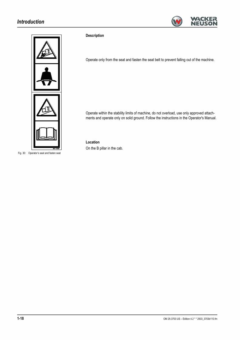
Description
Operate only from the seat and fasten the seat belt to prevent falling out of the machine.
Operate within the stability limits of machine, do not overload, use only approved attach-ments and operate only on solid ground. Follow the instructions in the Operator's Manual.
LocationOn the B pillar in the cab.
Fig. 30: Operator’s seat and fasten seat

OM 25-3703 US – Edition 4.2 * 2503_3703b110.fm 1-19
Introduction
1.11 Fire extinguisherThe fire extinguisher is not supplied with the machine.☞Retrofitting a fire extinguisher according to NFPA must be performed by an authorized
Wacker Neuson service center.☞Location:
➥ In the cab, on the left in driving direction behind the seat.☞ Installation:
• Mount the fire extinguisher on the cab profile according to the manufacturer’s instruc-tions.
• The maximum hole diamenter is 6mm (0.24’’)• The maximum number of holes is two.
Important!Check the fire extinguisher at regular intervals, also make sure it is safely mounted.

1-20 OM 25-3703 US – Edition 4.2 * * 2503_3703b110.fm
Introduction


![EC-Declaration of Conformity (No: DECL EC Accessories) · EC-Declaration of Conformity (No: DECL EC Accessories) [EN] Product model/product: See annex Name and address of the manufacturer](https://static.fdocuments.us/doc/165x107/5fbb98d10e2e8b16775d0667/ec-declaration-of-conformity-no-decl-ec-accessories-ec-declaration-of-conformity.jpg)