ba ks90-1 e 2011-07 - docs-apac.rs-online.com · 7.2 O 2 measurement ... para func Ada Err 4 1200...
84
PMA Prozeß- und Maschinen-Automation GmbH Industrial and process controller KS 90-1and KS 92-1 advanced line Operating manual English 9499-040-62911 Valid from: 8499 KS90-1 KS90-1 KS92-1 KS92-1
Transcript of ba ks90-1 e 2011-07 - docs-apac.rs-online.com · 7.2 O 2 measurement ... para func Ada Err 4 1200...

PMA Prozeß- und Maschinen-Automation GmbH
Industrial and process controllerKS 90-1and KS 92-1
advanced line
Operating manual
English
9499-040-62911
Valid from: 8499
KS90-1
KS90-1KS92-1
KS92-1

© PMA Prozeß- und Maschinen-Automation GmbH • Printed in Germany
All rights reserved. No part of this document may bereproduced or published in any form
or by any means without prior written permission from the copyright owner.
A publication of PMA Prozeß- und Maschinen Automation
P.O.Box 310229
D-34058 Kassel
Germany
û BlueControl
More efficiency in engineering,more overview in operating:
The projecting environment for the BluePort® controllers
ATTENTION!
Mini V
ersion
andUpdate
s on
or onPM
A-CD
www.pm
a-onlin
e.de
Description of symbolsin the text: on the device:
g General information a Follow the operating instructions
a General warning
l Attention: ESD-sensitive devices

KS 90-1 / KS 92-1 3
Contents
1 Mounting . . . . . . . . . . . . . . . . . . . . . . . . . . . . . . 5
2 Electrical connections . . . . . . . . . . . . . . . . . . . . . . . 6
2.1 Connecting diagram . . . . . . . . . . . . . . . . . . . . . . . 6
2.2 Terminal connection . . . . . . . . . . . . . . . . . . . . . . . . 7
3 Operation . . . . . . . . . . . . . . . . . . . . . . . . . . . . . 11
3.1 Front view . . . . . . . . . . . . . . . . . . . . . . . . . . . . 11
3.2 Behaviour after power-on . . . . . . . . . . . . . . . . . . . . . 12
3.3 Operating level . . . . . . . . . . . . . . . . . . . . . . . . . . 12
3.4 Error list / Maintenance manager . . . . . . . . . . . . . . . . . 13
3.5 Self-tuning . . . . . . . . . . . . . . . . . . . . . . . . . . . . . 16
3.5.1 Preparation for self-tuning . . . . . . . . . . . . . . . . . . . 16
3.5.2 Optimization after start-up or at the set-point . . . . . . . . . 17
3.5.3 Selecting the method ( ConF/ Cntr/ tunE). . . . . . . . . 17
3.5.4 Step attempt after start-up . . . . . . . . . . . . . . . . . . 18
3.5.5 Pulse attempt after start-up . . . . . . . . . . . . . . . . . . . 18
3.5.6 Optimization at the set-point . . . . . . . . . . . . . . . . . . 18
3.5.7 Optimization at the set-point for 3-point stepping controller. . 20
3.5.8 Self-tuning start . . . . . . . . . . . . . . . . . . . . . . . . . 21
3.5.9 Self-tuning cancellation . . . . . . . . . . . . . . . . . . . . . 21
3.5.10 Acknowledgement procedures in case ofunsuccessful self-tuning . . . . . . . . . . . . . . . . . . . . 22
3.5.11 Examples for self-tuning attempts . . . . . . . . . . . . . . . 23
3.6 Manual self-tuning. . . . . . . . . . . . . . . . . . . . . . . . . 24
3.7 Second PID parameter set . . . . . . . . . . . . . . . . . . . . . 25
3.8 Alarm handling . . . . . . . . . . . . . . . . . . . . . . . . . . 26
3.9 Operating structure . . . . . . . . . . . . . . . . . . . . . . . . 28
4 Configuration level . . . . . . . . . . . . . . . . . . . . . . . . 29
4.1 Configuration survey . . . . . . . . . . . . . . . . . . . 29
4.2 Configuration parameters . . . . . . . . . . . . . . . . . . . 30
4.3 Set-point processing . . . . . . . . . . . . . . . . . . . . . . . . 44
4.3.1 Set-point gradient / ramp . . . . . . . . . . . . . . . . . . . . 44
4.4 Switching behaviuor . . . . . . . . . . . . . . . . . . . . . . . . 45
4.4.1 Standard ( CyCl= 0 ) . . . . . . . . . . . . . . . . . . . . . 45
4 KS 90-1 / KS 92-1
4.4.2 Switching attitude linear ( CyCl= 1 ) . . . . . . . . . . . . . 45
4.4.3 Switching attitude non-linear ( CyCl= 2 ) . . . . . . . . . . 46
4.4.4 Heating and cooling with constant period ( CyCl= 3 ) . . . . 47
4.5 Configuration examples . . . . . . . . . . . . . . . . . . . . . . 48
4.5.1 On-Off controller / Signaller (inverse) . . . . . . . . . . . . . 48
4.5.2 2-point controller (inverse) . . . . . . . . . . . . . . . . . . . 49
4.5.3 3-point controller (relay & relay) . . . . . . . . . . . . . . . . 50
4.5.4 3-point stepping controller (relay & relay) . . . . . . . . . . . 51
4.5.5 Continuous controller (inverse) . . . . . . . . . . . . . . . . . 52
4.5.6 � � Y - Off controller / 2-point controller with pre-contact . 53
4.5.7 Continuous controller with position controller . . . . . . . . 54
4.5.8 Measured value output . . . . . . . . . . . . . . . . . . . . . 55
5 Parameter setting level . . . . . . . . . . . . . . . . . . . . . . 56
5.1 Parameter survey . . . . . . . . . . . . . . . . . . . . . . . 56
5.2 Parameters . . . . . . . . . . . . . . . . . . . . . . . . . . . . . 57
5.3 Input scaling . . . . . . . . . . . . . . . . . . . . . . . . . . . . 60
5.3.1 Input Inp.1 and InP.3 . . . . . . . . . . . 60
5.3.2 Input InP.2 . . . . . . . . . . . . . . . . . . . . . . . . . . 60
6 Calibration level . . . . . . . . . . . . . . . . . . . . . . . . . 61
7 Special functions . . . . . . . . . . . . . . . . . . . . . . . . . 64
7.1 DAC®– motor actuator monitoring . . . . . . . . . . . . . . . 64
7.2 O2 measurement . . . . . . . . . . . . . . . . . . . . . . . . . . 66
7.2.1 Connection . . . . . . . . . . . . . . . . . . . . . . . . . . . 66
7.2.2 Configuration:. . . . . . . . . . . . . . . . . . . . . . . . . . 67
7.3 Linearization. . . . . . . . . . . . . . . . . . . . . . . . . . . . 68
7.4 Loop alarm. . . . . . . . . . . . . . . . . . . . . . . . . . . . . 69
7.5 Heating current input / heating current alarm . . . . . . . . . . . 69
7.6 KS9x-1 as Modbus master. . . . . . . . . . . . . . . . . . . . . 70
7.7 Back-up controller (PROFIBUS) . . . . . . . . . . . . . . . . . 70
8 BlueControl . . . . . . . . . . . . . . . . . . . . . . . . . . . . 71
9 Versions . . . . . . . . . . . . . . . . . . . . . . . . . . . . . . 72
10 Technical data . . . . . . . . . . . . . . . . . . . . . . . . . . 74
11 Safety hints . . . . . . . . . . . . . . . . . . . . . . . . . . . . 78
11.1 Resetting to factory setting, . . . . . . . . . . . . . . . . . . . . 80
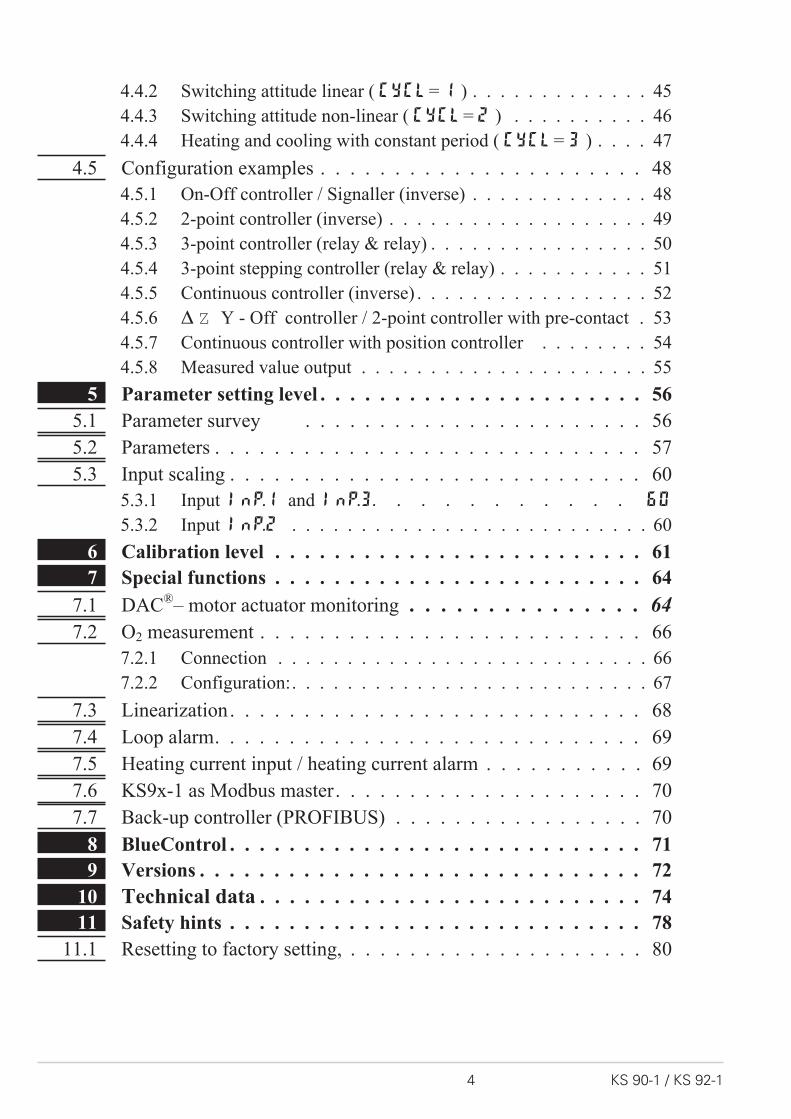
1 Mounting
a Fix the instrument only at top and bottom to avoid damaging it.
Safety switch:For access to the safety switch, the controller must be withdrawn from the hou-sing. Squeeze the top and bottom of the front bezel between thumb and forefingerand pull the controller firmly from the housing.
1 Factory setting 2 Default setting: display of all levelssuppressed, password PASS = OFF
l Caution! The unit contains ESD-sensitive components.
Mounting
KS 90-1 / KS 92-1 5
%max.95% rel.
max. 60°C
0°Cmin.
96(3
.78")
48 (1.89")
Loc
min.48 (1.89")
10 (0.4
")
1..10
(0.04..0.4")
118 (4.6
5")
45 +0,6
(1.77" )+0.02
92+
0,8
(3.6
2"
)+
0.0
3
Ü *
KS 90-1 advanced
1 2 3
è
12001199°C°F
SP.2SP.E
parafuncAda
Err
4
12001199°C°F
SP.2SP.E
parafuncAda
Err
1 2 3 4
F
KS 92-1 advanced
F
92+0,8
92+
0,8
9696
10118
1 2 3 4
KS 92-1 advanced
F
SP.
E
SP.
2
run
920.1921.2C
parafunc
AdaErr
SP.
E
SP.
2
run
o
locking switch
Loc open Access to the levels is as adjusted by means of BlueControl�
(engineering tool) 2
closed 1 all levels accessible wihout restriction
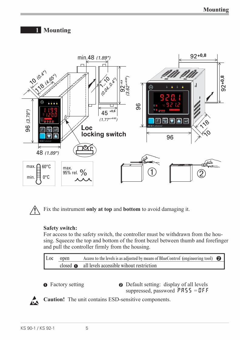
2 Electrical connections
2.1 Connecting diagram
g Dependent of order, the controller is fitted with :
w flat-pin terminals 1 x 6,3mm or 2 x 2,8mm to DIN 46 244 or
w screw terminals for 0,5 to 2,5mm²On instruments with screw terminals, the insulation must be stripped by min.12 mm. Choose end crimps accordingly!
Electrical connections
Connecting diagram 6 KS 90-1 / KS 92-1
1
3
4
5
6
7
8
9
10
11
12
13
14
15
17
(2)
(16)
mA
(mV)
(mV)
Volt
mA
INP2
INP3
INP1
di2
di1123
456
789
101112
131415
Op
tio
n
1
2
3
4
5
6
7
8
9
10
11
12
13
14
15
17(16)
OUT1
OUT2
OUT3
OUT4
90...250V
24 V UC
0%
100%
V
V
mAHC
KS90-1. -2
5
...
KS90-1. -4 ...
KS90-1. -5 ...
KS90-1..-.1...
di2
di3
UT
RXD-B
GND
RXD-A
TXD-B
TXD-A
RS485 RS422
Modbus RTU
RGND
DATA B
DATA A
9
0
8
3
2
17
6
5
4
a b c d e
f
g
ab cd
e
+24V DC
24V GND
OUT5OUT6
!
VP (5V)
DGND
RxD/TxD-N
RxD/TxD-P
PR
OF
IBU
S-D
PSchirm/Screen
59
48
37
26
1
59
48
37
26
1
390 [
390 [
220 [
DGND
VP (5V)
max.1200m
Ad
ap
ter
Profibus DP
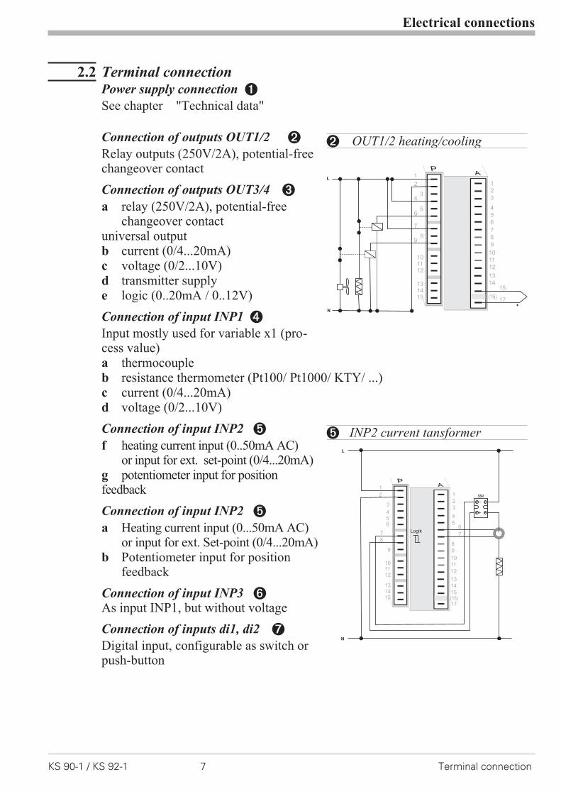
2.2 Terminal connectionPower supply connection 1
See chapter "Technical data"
Connection of outputs OUT1/2 2
Relay outputs (250V/2A), potential-freechangeover contact
Connection of outputs OUT3/4 3
a relay (250V/2A), potential-freechangeover contact
universal outputb current (0/4...20mA)c voltage (0/2...10V)d transmitter supplye logic (0..20mA / 0..12V)
Connection of input INP1 4
Input mostly used for variable x1 (pro-cess value)a thermocoupleb resistance thermometer (Pt100/ Pt1000/ KTY/ ...)c current (0/4...20mA)d voltage (0/2...10V)
Connection of input INP2 5
f heating current input (0..50mA AC)or input for ext. set-point (0/4...20mA)
g potentiometer input for positionfeedback
Connection of input INP2 5
a Heating current input (0...50mA AC)or input for ext. Set-point (0/4...20mA)
b Potentiometer input for positionfeedback
Connection of input INP3 6As input INP1, but without voltage
Connection of inputs di1, di2 7
Digital input, configurable as switch orpush-button
Electrical connections
KS 90-1 / KS 92-1 7 Terminal connection
6
9
101112
131415
1
2
3
4
5
6
7
8
9
10
11
12
13
14
17(16)
L
N
+
5
43
2
1
8
7
15
2 OUT1/2 heating/cooling
L
N
+
_SSR
3
456
9
101112
131415
1
2
3
4
5
8
9
10
11
12
13
14
15
17(16)
2
1
8
76
7Logik
5 INP2 current tansformer

Connection of inputs di2/3 8 (option)
Digital inputs (24VDC external), galvanically isolated, configurable as switch orpush-button
Connection of output UT 9 (option)
Supply voltage connection for external energization
Connection of outputs OUT5/6 0 (option)
Digital outputs (opto-coupler), galvanic isolated, common positive control volta-ge, output rating: 18...32VDC
Connection of bus interface ! (option)
PROFIBUS DP or RS422/485 interface with Modbus RTU protocol
g Analog outputs OUT3 or OUT4 and transmitter supply UT are connected todifferent voltage potentials. Therefore, take care not to make an external galvanicconnection between OUT3/4 and UT with analog outputs!
Electrical connections
Terminal connection 8 KS 90-1 / KS 92-1
131415
Op
tio
n
17(16)
1
3
4
5
6
7
8
9
10
11
12
13
14
15
17
(2)
(16)
+24VDC
5mA
5mA
0V
1
2
3
K
+
-
+-17,5V
22mA
14
13+
-15
OUT3
10
11
12
J
J
89 di2/3, 2-wire transmitter supply

* Interface description Modbus RTU in separate manual: see page 72.
Electrical connections
KS 90-1 / KS 92-1 9 Terminal connection
1
2
3
K
+
-
+
-
13V22mA
131415
11
1213
17(16)
1415
12
11
10
3 OUT3 transmitter supply
1
3
4
5
6
7
8
9
10
11
12
13
14
15
17
(2)
(16)
op
tio
n
1
3
4
5
6
7
8
9
10
11
12
13
14
15
17
(2)
(16)
op
tio
n
1
3
4
5
6
7
8
9
10
11
12
13
14
15
17
(2)
(16)
op
tio
n
11
12
13
14
15
10
11
12
13
14
15
10
11
12
13
14
15
RGND RGND RGND
RT
RS485-RS232converter
PC
DATA A
DATA B
DATA A
DATA B
DATA A
DATA B
J
max. 1000m"Twisted Pair” cable
10
RT
R=100 Ohm
RGND connection optional
R = 120...200 OhmT
R = 120...200 OhmT
9 RS485 interface (with RS232-RS485 interface converter) *
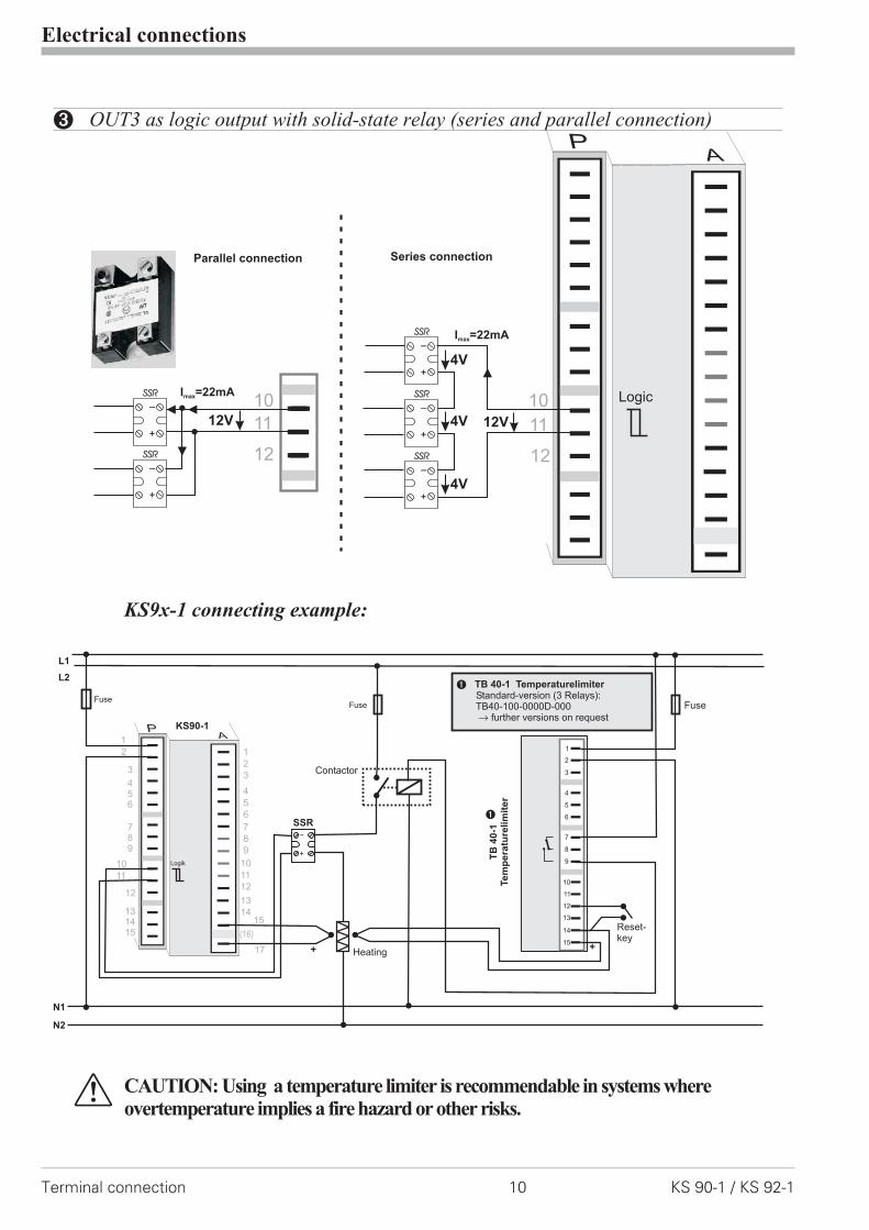
KS9x-1 connecting example:
a CAUTION: Using a temperature limiter is recommendable in systems whereovertemperature implies a fire hazard or other risks.
Electrical connections
Terminal connection 10 KS 90-1 / KS 92-1
12
+
_SSR
+
_SSR
+
_SSR
Series connectionParallel connection
+
_SSR
+
_SSR
4V
4V
4V 12V
I =22mAmax
I =22mAmax
12V 11
1010
11
12
Logic
3 OUT3 as logic output with solid-state relay (series and parallel connection)
+
_
L1
L2
N1
N2
Fuse
1
2
3
4
7
5
8
6
9
10
11
12
13
14
15
Fuse
1
Fuse
SSR
Reset-key
Contactor
Heating
1 TB 40-1 TemperaturelimiterStandard-version (3 Relays):TB40-100-0000D-000
further versions on requestr
+ +
3
456
789
11
131415
1
2
3
4
5
6
7
8
9
10
11
12
13
14
17
(16)
15
2
1
12
10 Logik
KS90-1
TB
40-1
Te
mp
era
ture
lim
ite
r
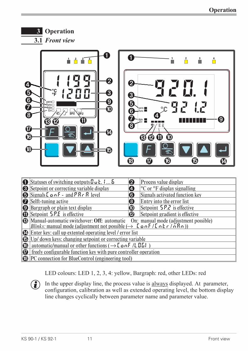
3 Operation
3.1 Front view
1 Statuses of switching outputsOuT.1...6 2 Process value display3 Setpoint or correcting variable display 4 °C or °F display signalling5 SignalsConF- andPArA level 6 Signals activated function key7 Selft-tuning active 8 Entry into the error list9 Bargraph or plain text display 0 Setpoint SP.2 is effective! Setpoint SP.E is effective " Setpoint gradient is effective§ Manual-automatic switchover: Off: automatic On: manual mode (adjustment possible)
Blinks: manual mode (adjustment not possible (r ConF/Cntr/MAn))$ Enter key: call up extented operating level / error list% Up/ down keys: changing setpoint or correcting variable& automatic/manual or other functions (rConF /LOGI)/ freely configurable function key with pure controller operation( PC connection for BlueControl (engineering tool)
LED colours: LED 1, 2, 3, 4: yellow, Bargraph: red, other LEDs: red
g In the upper display line, the process value is always displayed. At parameter,configuration, calibration as well as extended operating level, the bottom displayline changes cyclically between parameter name and parameter value.
Operation
KS 90-1 / KS 92-1 11 Front view
1 2 3 4
FS
P.E
SP.
2
920.1921.2C
parafunc
AdaErr
SP.
E
SP.
2
o
12001199°C°F
SP.2SP.E
parafuncAda
Err
F
1 2 3 4 1 2 3 4
SP.
E
SP.
2
Cparafunc
AdaErr
SP.
E
SP.
2
o
12001199°C°F
parafuncAdaA
Err
1 2 3 4 1 2 3 4
SP.
E
SP.
2
Cparafunc
AdaErr
SP.
E
SP.
2
o
12001199°C°F
parafuncAda
Err
1 2 3 4
(
1
2
3
456
$
78
%
&
(
1 2 3 4
SP.
E
SP.
2
Cparafunc
AdaErr
SP.
E
SP.
2
o
12001199°C°F
parafuncAda
Err
1 2 3 4 1 2 3 4
SP.
E
SP.
2
Cparafunc
AdaErr
SP.
E
SP.
2
o
12001199°C°F
parafuncAda
Err
1 2 3 4 1 2 3 4
SP.
E
SP.
2
Cparafunc
AdaErr
SP.
E
SP.
2
o
12001199°C°F
parafuncAda
Err
1 2 3 4 1 2 3 4
SP.
E
SP.
2
Cparafunc
AdaErr
SP.
E
SP.
2
o
12001199°C°F
parafuncAda
Err
1 2 3 4 1 2 3 4
SP.
E
SP.
2
Cparafunc
AdaErr
SP.
E
SP.
2
o
12001199°C°F
parafuncAda
Err
1 2 3 4
/
1 2 3 4
SP.
E
SP.
2
Cparafunc
AdaErr
SP.
E
SP.
2
o
12001199°C°F
parapfuncfAda
Err
1 2 3 4 1 2 3 4
SP.
E
SP.
2
Cparafunc
AdaErr
SP.
E
SP.
2
o
12001199°C°F
parafuncAda
Err
1 2 3 4 1 2 3 4
SP.
E
SP.
2
Cparafunc
AdaErr
SP.
E
SP.
2
o
12001199°C°F
parafuncAda
Err
1 2 3 4 1 2 3 4
SP.
E
SP.
2
Cparafunc
AdaErr
SP.
E
SP.
2
o
12001199°C°F
parafuncAda
Err
1 2 3 4 1 2 3 4
SP.
E
SP.
2
Cparafunc
AdaErr
SP.
E
SP.
2
o
12001199°C°F
parafuncAda
Err
1 2 3 4 1 2 3 4
SP.
E
SP.
2
Cparafunc
AdaErr
SP.
E
SP.
2
o
12001199°C°F
parafuncAda
Err
1 2 3 4
9
1 2 3 4
SP.
E
SP.
2
Cparafunc
AdaErr
SP.
E
SP.
2
o
12001199°C°F
parafuncAda
Err
1 2 3 4
0
1 2 3 4
SP.
E
SP.
2
Cparafunc
AdaErr
SP.
E
SP.
2
o
12001199°C°F
parafuncAda
Err
1 2 3 4
!
§"
!
1 2 3 4
SP.
E
SP.
2
Cparafunc
AdaErr
SP.
E
SP.
2
o
12001199°C°F
parafuncAda
Err
1 2 3 4 1 2 3 4
SP.
E
SP.
2
Cparafunc
AdaErr
SP.
E
SP.
2
o
12001199°C°F
parafuncAda
Err
1 2 3 4 1 2 3 4
SP.
E
SP.
2
Cparafunc
AdaErr
SP.
E
SP.
2
o
12001199°C°F
parafuncAda
Err
1 2 3 4
2
1 2 3 4
SP.
E
SP.
2
Cparafunc
AdaErr
SP.
E
SP.
2
o
12001199°C°F
parafuncAda
Err
1 2 3 4
5
3
4
1 2 3 4
SP.
E
SP.
2
Cparafunc
AdaErr
SP.
E
SP.
2
o
12001199°C°F
parafuncAda
Err
1 2 3 4 1 2 3 4
SP.
E
SP.
2
Cparafunc
AdaErr
SP.
E
SP.
2
o
12001199°C°F
parafuncAda
Err
1 2 3 4
9
0
1 2 3 4
SP.
E
SP.
2
Cparafunc
AdaErr
SP.
E
SP.
2
o
12001199°C°F
parafuncAda
Err
1 2 3 4 1 2 3 4
SP.
E
SP.
2
Cparafunc
AdaErr
SP.
E
SP.
2
o
12001199°C°F
parafuncAda
Err
1 2 3 4
!!
§"
1 2 3 4
SP.
E
SP.
2
Cparafunc
AdaErr
SP.
E
SP.
2
o
12001199°C°F
parafuncAda
Err
1 2 3 4 1 2 3 4
SP.
E
SP.
2
Cparafunc
AdaErr
SP.
E
SP.
2
o
12001199°C°F
parafuncAda
Err
1 2 3 4
78
1 2 3 4
SP.
E
SP.
2
Cparafunc
AdaErr
SP.
E
SP.
2
o
12001199°C°F
parafuncAda
Err
1 2 3 4
$%&/(
1 2 3 4
SP.
E
SP.
2
Cparafunc
AdaErr
SP.
E
SP.
2
o
12001199°C°F
parafuncAda
Err
1 2 3 4 1 2 3 4
SP.
E
SP.
2
Cparafunc
AdaErr
SP.
E
SP.
2
o
12001199°C°F
parafuncAda
Err
1 2 3 4
6
1 2 3 4
SP.
E
SP.
2
Cparafunc
AdaErr
SP.
E
SP.
2
o
12001199°C°F
parafuncAda
Err
1 2 3 4
556
1
2
3
1 2 3 4
SP.
E
SP.
2
Cparafunc
AdaErr
SP.
E
SP.
2
o
12001199°C°F
parafuncAda
Err
1 2 3 4
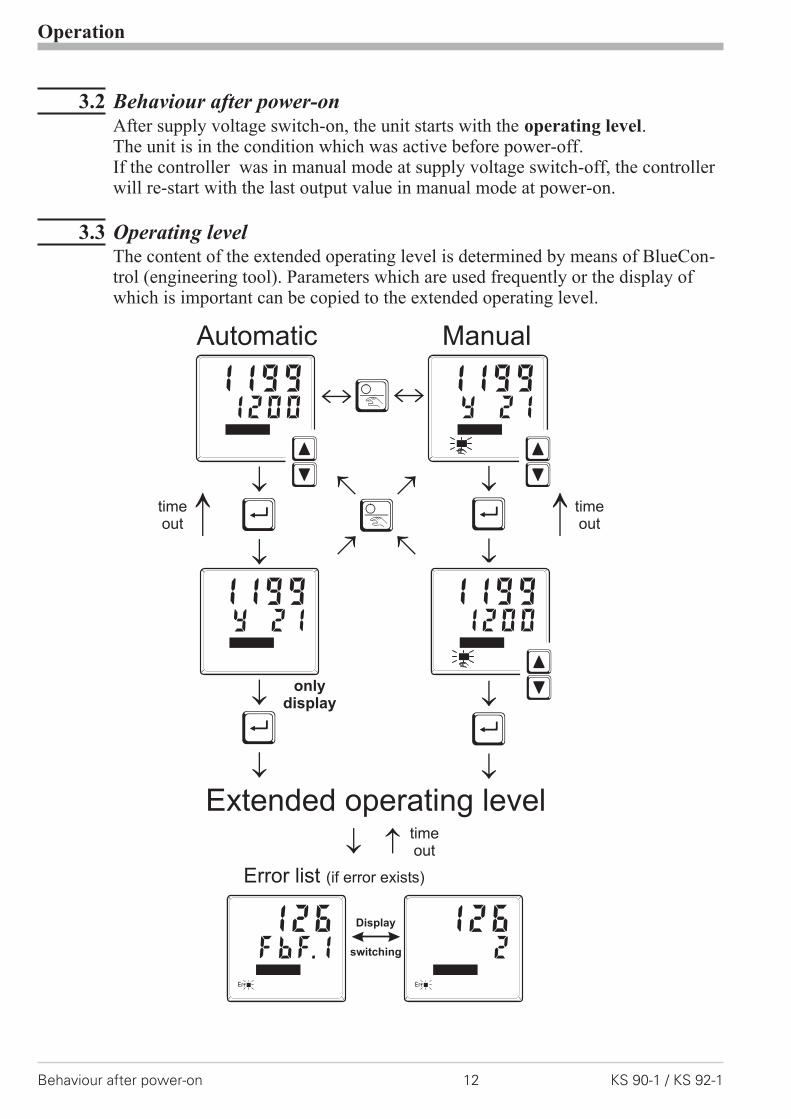
3.2 Behaviour after power-onAfter supply voltage switch-on, the unit starts with the operating level.The unit is in the condition which was active before power-off.If the controller was in manual mode at supply voltage switch-off, the controllerwill re-start with the last output value in manual mode at power-on.
3.3 Operating levelThe content of the extended operating level is determined by means of BlueCon-trol (engineering tool). Parameters which are used frequently or the display ofwhich is important can be copied to the extended operating level.
Operation
Behaviour after power-on 12 KS 90-1 / KS 92-1
Ò
ÒÙ
Ù
Ù
Ù
Automatic
Extended operating level
Manual
ii
onlydisplay
switching
Display
Error list (if error exists)
Y 211199
12001199
ÈÌ
ÈÌ
Y 211199
12001199
ÈÌ
FbF.1126
Err
2126
Err
timeout
timeout
timeout
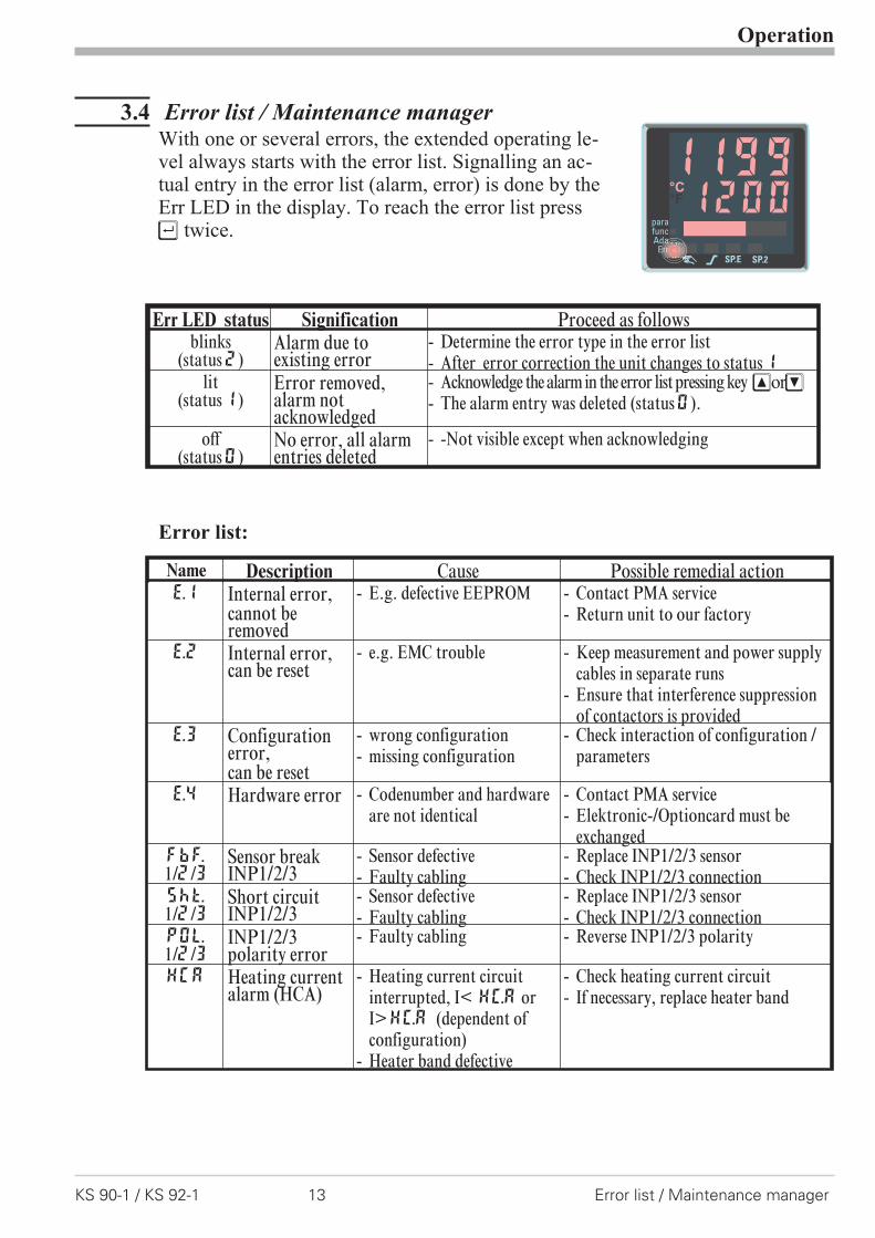
3.4 Error list / Maintenance managerWith one or several errors, the extended operating le-vel always starts with the error list. Signalling an ac-tual entry in the error list (alarm, error) is done by theErr LED in the display. To reach the error list pressÙ twice.
Error list:
Operation
KS 90-1 / KS 92-1 13 Error list / Maintenance manager
12001199°C°F
SP.2SP.E
parafuncAda
Err
Err LED status Signification Proceed as followsblinks
(status2)Alarm due toexisting error
- Determine the error type in the error list- After error correction the unit changes to status1
lit(status1)
Error removed,alarm notacknowledged
- Acknowledge the alarm in the error list pressing key ÈorÌ- The alarm entry was deleted (status0).
off(status0)
No error, all alarmentries deleted
- -Not visible except when acknowledging
Name Description Cause Possible remedial actionE.1 Internal error,
cannot beremoved
- E.g. defective EEPROM - Contact PMA service- Return unit to our factory
E.2 Internal error,can be reset
- e.g. EMC trouble - Keep measurement and power supplycables in separate runs
- Ensure that interference suppressionof contactors is provided
E.3 Configurationerror,can be reset
- wrong configuration- missing configuration
- Check interaction of configuration /parameters
E.4 Hardware error - Codenumber and hardwareare not identical
- Contact PMA service- Elektronic-/Optioncard must be
exchangedFbF.1/2/3
Sensor breakINP1/2/3
- Sensor defective- Faulty cabling
- Replace INP1/2/3 sensor- Check INP1/2/3 connection
Sht.1/2/3
Short circuitINP1/2/3
- Sensor defective- Faulty cabling
- Replace INP1/2/3 sensor- Check INP1/2/3 connection
POL.1/2/3
INP1/2/3polarity error
- Faulty cabling - Reverse INP1/2/3 polarity
HCA Heating currentalarm (HCA)
- Heating current circuitinterrupted, I< HC.A orI>HC.A (dependent ofconfiguration)
- Heater band defective
- Check heating current circuit- If necessary, replace heater band
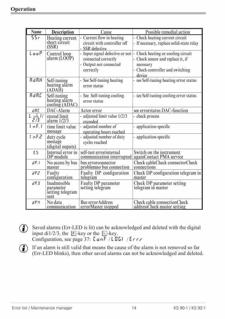
g Saved alarms (Err-LED is lit) can be acknowledged and deleted with the digitalinput di1/2/3, the è-key or the Ò-key.Configuration, see page 37: ConF / LOGI / Err.r
g If an alarm is still valid that means the cause of the alarm is not removed so far(Err-LED blinks), then other saved alarms can not be acknowledged and deleted.
Operation
Error list / Maintenance manager 14 KS 90-1 / KS 92-1
Name Description Cause Possible remedial actionSSr Heating current
short circuit(SSR)
- Current flow in heatingcircuit with controller off
- SSR defective
- Check heating current circuit- If necessary, replace solid-state relay
LooP Control loopalarm (LOOP)
- Input signal defective or notconnected correctly
- Output not connectedcorrectly
- Check heating or cooling circuit- Check sensor and replace it, if
necessary- Check controller and switching
deviceAdA.H Self-tuning
heating alarm(ADAH)
- See Self-tuning heatingerror status
- see Self-tuning heating error status
AdA.C Self-tuningheating alarmcooling (ADAC)
- See Self-tuning coolingerror status
- see Self-tuning cooling error status
dAC DAC-Alarm Actor error see errorstatus DAC-functionLiM.1/2/3
stored limitalarm 1/2/3
- adjusted limit value 1/2/3exceeded
- check process
Inf.1 time limit valuemessage
- adjusted number ofoperating hours reached
- application-specific
Inf.2 duty cyclemessage(digital ouputs)
- adjusted number of dutycycles reached
- application-specific
E.5 Internal error inDP module
self-test errorinternalcommunication interrupted
Switch on the instrumentagainContact PMA service
dp.1 No access by busmaster
bus errorconnectorproblemno bus connection
Check cableCheck connectorCheckconnections
dp.2 Faultyconfiguration
Faulty DP configurationtelegram
Check DP configuration telegram inmaster
dp.3 Inadmissibleparametersetting telegramsent
Faulty DP parametersetting telegram
Check DP parameter settingtelegram in master
dp.4 No datacommunication
Bus errorAddresserrorMaster stopped
Check cable connectionCheckaddressCheck master setting
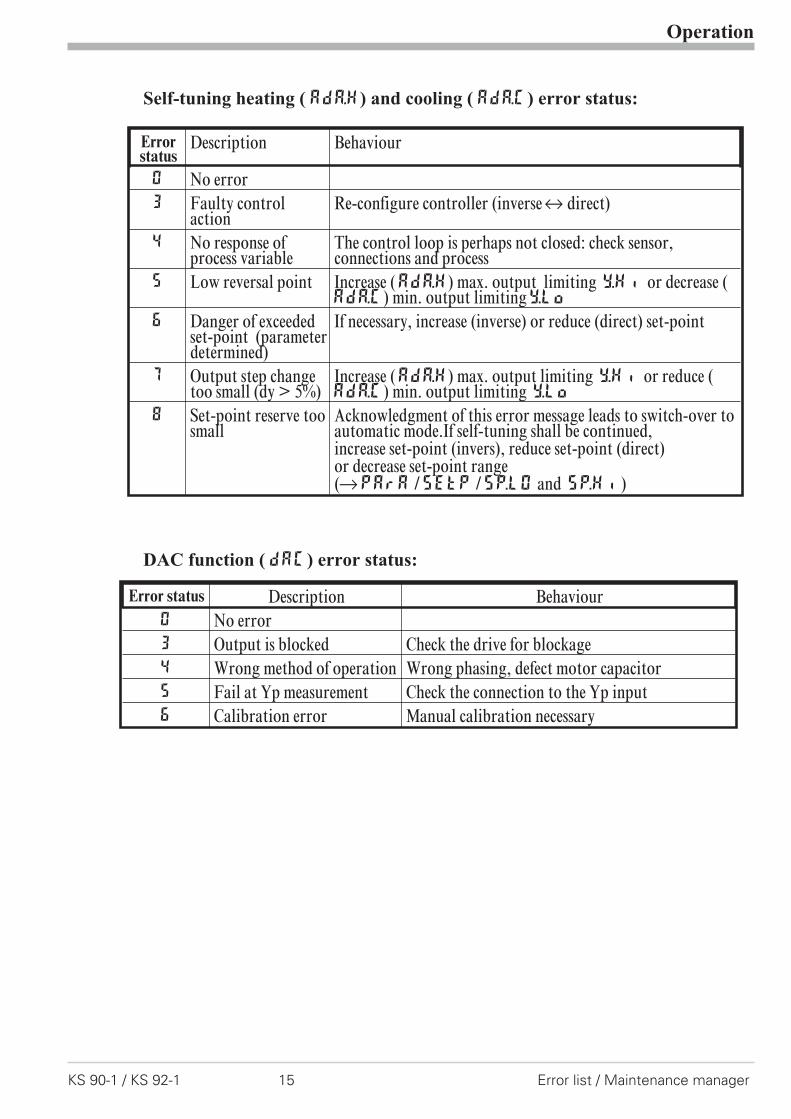
Self-tuning heating ( ADA.H) and cooling ( ADA.C) error status:
DAC function ( DAC) error status:
Operation
KS 90-1 / KS 92-1 15 Error list / Maintenance manager
Error status Description Behaviour0 No error3 Output is blocked Check the drive for blockage4 Wrong method of operation Wrong phasing, defect motor capacitor5 Fail at Yp measurement Check the connection to the Yp input6 Calibration error Manual calibration necessary
Errorstatus
Description Behaviour
0 No error3 Faulty control
actionRe-configure controller (inversei direct)
4 No response ofprocess variable
The control loop is perhaps not closed: check sensor,connections and process
5 Low reversal point Increase (ADA.H) max. output limiting Y.Hi or decrease (ADA.C) min. output limitingY.Lo
6 Danger of exceededset-point (parameterdetermined)
If necessary, increase (inverse) or reduce (direct) set-point
7 Output step changetoo small (dy > 5%)
Increase (ADA.H) max. output limiting Y.Hi or reduce (ADA.C) min. output limiting Y.Lo
8 Set-point reserve toosmall
Acknowledgment of this error message leads to switch-over toautomatic mode.If self-tuning shall be continued,increase set-point (invers), reduce set-point (direct)or decrease set-point range(rPArA /SEtp /SP.LO and SP.Hi )

3.5 Self-tuningFor determination of optimum process parameters, self-tuning is possible.
After starting by the operator, the controller makes an adaptation attempt, where-by the process characteristics are used to calculate the parameters for fast line-outto the set-point without overshoot.
The following parameters are optimized when self-tuning:
Parameter set 1:
Pb1 - Proportional band 1 (heating) in engineering units [e.g. °C]ti1 - Integral time 1 (heating) in [s]r only, unless set to OFF
td1 - Derivative time 1 (heating) in [s]r only, unless set to OFF
t1 - Minimum cycle time 1 (heating) in [s]r only, unless Adt0 wasset to “no self-tuning” during configuration by means ofBlueControl®.
Pb2 - Proportional band 2 (cooling) in engineering units [e.g. °C]ti2 - Integral time 2 (cooling) in [s]r only, unless set to OFFtd2 - Derivative time 2 (cooling) in [s]r only, unless set to OFF
t2 - Minimum cycle time 2 (cooling) in [s] r only, unless Adt0was set to “no self-tuning” during configuration by means ofBlueControl® .
Parameter set 2: analogous to parameter set 1 (see page 25)
3.5.1 Preparation for self-tuning
w Adjust the controller measuring range as control range limits. Set valuesrnG.L and rnG.H to the limits of subsequent control.(ConfigurationrControllerrlower and upper control range limits)ConFrCntrr rnG.L and rnG.H
w Determine which parameter set shall be optimized.-The instantaneously effective parameter set is optimized.r Activate the relevant parameter set (1 or 2).
w Determine which parameter set shall be optimized (see tables above).
w Select the self-tuning methodsee chapter 3.5.3-Step attempt after start-up-Pulse attempt after start-up-Optimization at the set-point
Operation
Self-tuning 16 KS 90-1 / KS 92-1
3.5.2 Optimization after start-up or at the set-point
The two methods are optimization after start-up and at the set-point.As control parameters are always optimal only for a limited process range, vari-ous methods can be selected dependent of requirements. If the process behaviouris very different after start-up and directly at the set-point, parameter sets 1 and 2can be optimized using different methods. Switch-over between parameter setsdependent of process status is possible (see page ).
Optimization after start-up: (see page 4)Optimization after start-up requires a certain separation between process valueand set-point. This separation enables the controller to determine the control pa-rameters by evaluation of the process when lining out to the set-point.This method optimizes the control loop from the start conditions to the set-point,whereby a wide control range is covered.We recommend selecting optimization method “Step attempt after start-up”
with tunE = 0 first. Unless this attempt is completed successfully, we recom-mend a “Pulse attempt after start-up”.
Optimization at the set-point: (see page 18)For optimizing at the set-point, the controller outputs a disturbance variable to theprocess. This is done by changing the output variable shortly. The process valuechanged by this pulse is evaluated. The detected process parameters are conver-ted into control parameters and saved in the controller.This procedure optimizes the control loop directly at the set-point. The advantageis in the small control deviation during optimization.
3.5.3 Selecting the method ( ConF/ Cntr/ tunE)
Selection criteria for the optimization method:
Step attempt after start-up Pulse attempt afterstart-up
Optimization at theset-point
tunE= 0 sufficient set-point reserveis provided
sufficient set-point reserve isnot provided
tunE= 1 sufficient set-pointreserve is provided
sufficient set-point reserve isnot provided
tunE= 2 always step attempt afterstart-up
Sufficient set-point reserve:inverse controller:(with process value < set-point- (10% of rnGH - rnGL)direct controller: (with process value > set-point + (10% of rnGH - rnGL)
Operation
KS 90-1 / KS 92-1 17 Self-tuning
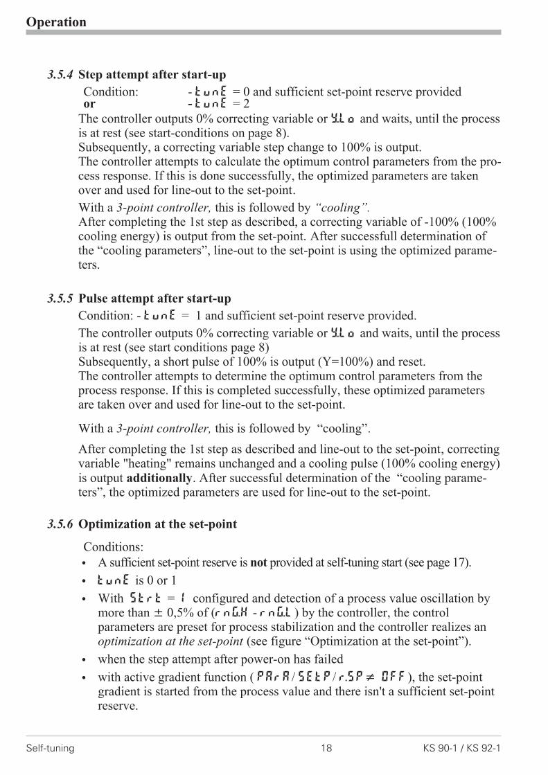
3.5.4 Step attempt after start-up
Condition: - tunE = 0 and sufficient set-point reserve providedor - tunE = 2
The controller outputs 0% correcting variable or Y.Lo and waits, until the processis at rest (see start-conditions on page 8).Subsequently, a correcting variable step change to 100% is output.The controller attempts to calculate the optimum control parameters from the pro-cess response. If this is done successfully, the optimized parameters are takenover and used for line-out to the set-point.
With a 3-point controller, this is followed by “cooling”.After completing the 1st step as described, a correcting variable of -100% (100%cooling energy) is output from the set-point. After successfull determination ofthe “cooling parameters”, line-out to the set-point is using the optimized parame-ters.
3.5.5 Pulse attempt after start-up
Condition: - tunE = 1 and sufficient set-point reserve provided.
The controller outputs 0% correcting variable or Y.Lo and waits, until the processis at rest (see start conditions page 8)Subsequently, a short pulse of 100% is output (Y=100%) and reset.The controller attempts to determine the optimum control parameters from theprocess response. If this is completed successfully, these optimized parametersare taken over and used for line-out to the set-point.
With a 3-point controller, this is followed by “cooling”.
After completing the 1st step as described and line-out to the set-point, correctingvariable "heating" remains unchanged and a cooling pulse (100% cooling energy)is output additionally. After successful determination of the “cooling parame-ters”, the optimized parameters are used for line-out to the set-point.
3.5.6 Optimization at the set-point
Conditions:
w A sufficient set-point reserve is not provided at self-tuning start (see page 17).
w tunE is 0 or 1
w With Strt = 1 configured and detection of a process value oscillation bymore than � 0,5% of (rnG.H - rnG.L) by the controller, the controlparameters are preset for process stabilization and the controller realizes anoptimization at the set-point (see figure “Optimization at the set-point”).
w when the step attempt after power-on has failed
w with active gradient function ( PArA/ SETP/ r.SP� OFF), the set-pointgradient is started from the process value and there isn't a sufficient set-pointreserve.
Operation
Self-tuning 18 KS 90-1 / KS 92-1

Optimization-at-the-set-point procedure:The controller uses its instantaneous parameters for control to the set-point. In li-ned out condition, the controller makes a pulse attempt. This pulse reduces thecorrecting variable by max. 20% 1, to generate a slight process value unders-hoot. The changing process is analyzed and the parameters thus calculated are re-corded in the controller. The optimized parameters are used for line-out totheset-point.
With a 3-point controller, optimization for the “heating“ or “cooling” parametersoccurs dependent of the instantaneous condition.These two optimizations must be started separately.
1 If the correcting variable is too low for reduction in lined out condition it isincreased by max. 20%.
Operation
KS 90-1 / KS 92-1 19 Self-tuning
set-point
process value
correctingvariable
Optimization at the set-point
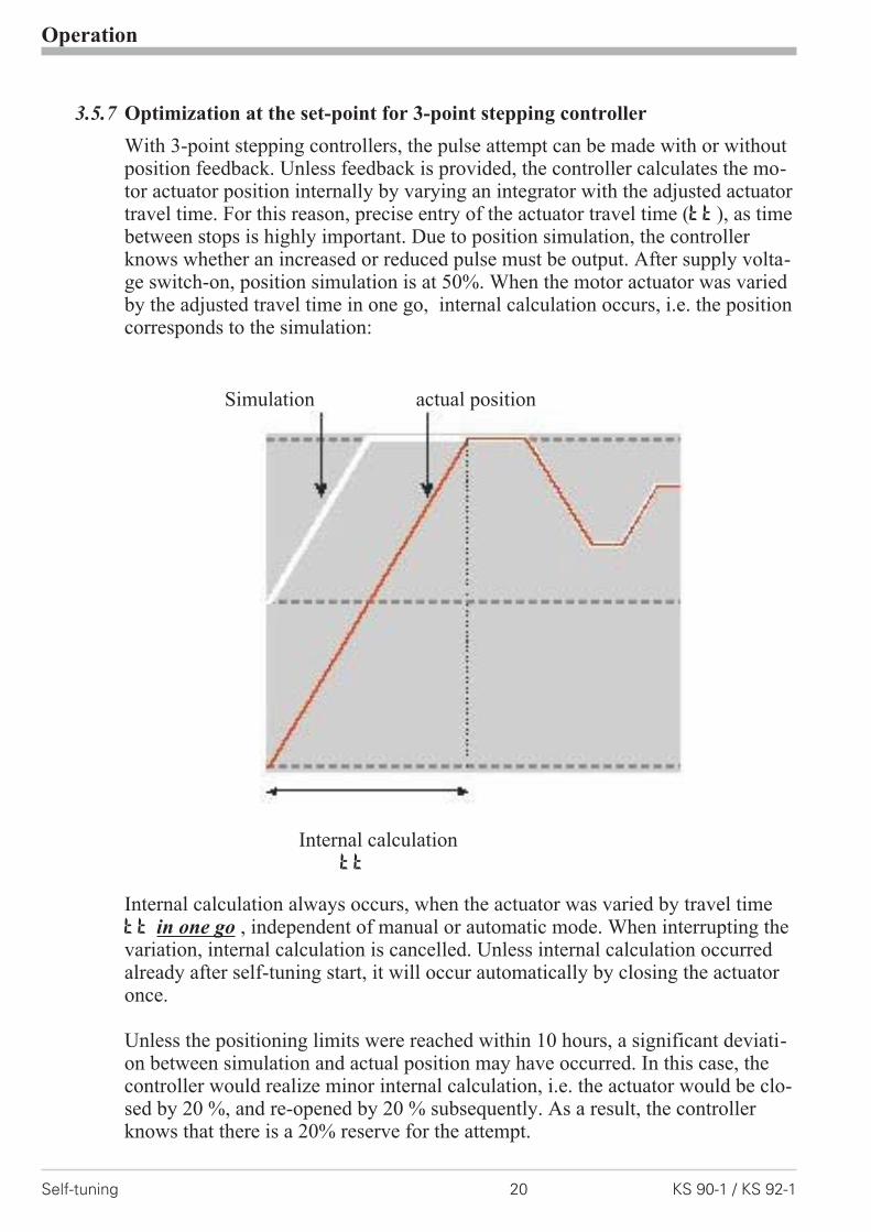
3.5.7 Optimization at the set-point for 3-point stepping controller
With 3-point stepping controllers, the pulse attempt can be made with or withoutposition feedback. Unless feedback is provided, the controller calculates the mo-tor actuator position internally by varying an integrator with the adjusted actuatortravel time. For this reason, precise entry of the actuator travel time (tt), as timebetween stops is highly important. Due to position simulation, the controllerknows whether an increased or reduced pulse must be output. After supply volta-ge switch-on, position simulation is at 50%. When the motor actuator was variedby the adjusted travel time in one go, internal calculation occurs, i.e. the positioncorresponds to the simulation:
Simulation actual position
Internal calculationtt
Internal calculation always occurs, when the actuator was varied by travel timett in one go , independent of manual or automatic mode. When interrupting thevariation, internal calculation is cancelled. Unless internal calculation occurredalready after self-tuning start, it will occur automatically by closing the actuatoronce.
Unless the positioning limits were reached within 10 hours, a significant deviati-on between simulation and actual position may have occurred. In this case, thecontroller would realize minor internal calculation, i.e. the actuator would be clo-sed by 20 %, and re-opened by 20 % subsequently. As a result, the controllerknows that there is a 20% reserve for the attempt.
Operation
Self-tuning 20 KS 90-1 / KS 92-1
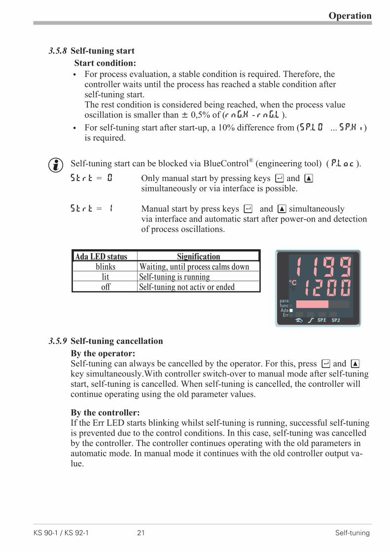
3.5.8 Self-tuning start
Start condition:
w For process evaluation, a stable condition is required. Therefore, thecontroller waits until the process has reached a stable condition afterself-tuning start.The rest condition is considered being reached, when the process valueoscillation is smaller than � 0,5% of (rnG.H - rnG.L).
w For self-tuning start after start-up, a 10% difference from (SP.LO ... SP.Hi)is required.
g Self-tuning start can be blocked via BlueControl® (engineering tool) ( P.Loc).
Strt = 0 Only manual start by pressing keys Ù and Èsimultaneously or via interface is possible.
Strt = 1 Manual start by press keys Ù and È simultaneouslyvia interface and automatic start after power-on and detectionof process oscillations.
3.5.9 Self-tuning cancellation
By the operator:Self-tuning can always be cancelled by the operator. For this, press Ù and Èkey simultaneously.With controller switch-over to manual mode after self-tuningstart, self-tuning is cancelled. When self-tuning is cancelled, the controller willcontinue operating using the old parameter values.
By the controller:If the Err LED starts blinking whilst self-tuning is running, successful self-tuningis prevented due to the control conditions. In this case, self-tuning was cancelledby the controller. The controller continues operating with the old parameters inautomatic mode. In manual mode it continues with the old controller output va-lue.
Operation
KS 90-1 / KS 92-1 21 Self-tuning
Ada LED status Significationblinks Waiting, until process calms down
lit Self-tuning is runningoff Self-tuning not activ or ended 1200
1199°C°F
SP.2SP.E
parafuncAda
Err

3.5.10 Acknowledgement procedures in case of unsuccessful self-tuning
1. Press keys Ù and È simultaneously:The controller continues controlling using the old parameters in automaticmode. The Err LED continues blinking, until the self-tuning error wasacknowledged in the error list.
2. Press key Ò (if configured):The controller goes to manual mode. The Err LED continues blinking,until the self-tuning error was acknowleged in the error list.
3. Press key Ù :Display of error list at extended operating level. After acknowledgementof the error message, the controller continues control in automatic mode usingthe old parameters.
Cancellation causes:r page 15: "Error status self-tuning heating ( ADA.H) and cooling ( ADA.C)"
Operation
Self-tuning 22 KS 90-1 / KS 92-1

3.5.11 Examples for self-tuning attempts
(controller inverse, heating or heating/cooling)
Start: heating power switched onHeating power Y is switched off (1).When the change of process value Xwas constant during one minute (2),the power is switched on (3).At the reversal point, the self-tuning at-tempt is finished and the new parameterare used for controlling to set-point W.
Start: heating power switched offThe controller waits 1,5 minutes (1).Heating power Y is switched on (2).At the reversal point, the self-tuningattempt is finished and control to theset-point is using the new parameters.
Self-tuning at the set-point aThe process is controlled to theset-point. With the control deviationconstant during a defined time (1)(i.e. constant separation of process valueand set-point), the controller outputs areduced correcting variable pulse (max.20%) (2). After determination of thecontrol parameters using the processcharacteristic (3), control is startedusing the new parameters (4).
Three-point controller aThe parameter for heating and cooling aredetermined in two attempts. The heatingpower is switched on (1). Heating para-meters Pb1, ti1, td1 and t1 are de-termined at the reversal point. Control tothe set-point occurs(2). With constantcontrol deviation, the controller provides acooling correcting variable pulse (3). Af-ter determining its cooling parametersPb2, ti2, td2 and t2 (4) from theprocess characteristics , control operation is started using the new parameters (5).
a During phase 3, heating and cooling are done simultaneously!
Operation
KS 90-1 / KS 92-1 23 Self-tuning
t+100%Y 0%-100%
XW
t reversalpoint
Start r 1 2
3
4 5
r t
t
2
100%Y
0%
XW
1 3
blinks
4
r t
Start r
t
2
100%Y
0%
XW
Start r 1 3 t reversal point
blinks
t100%
Y0%
XW
start r 1 2 t reversal point
blinks
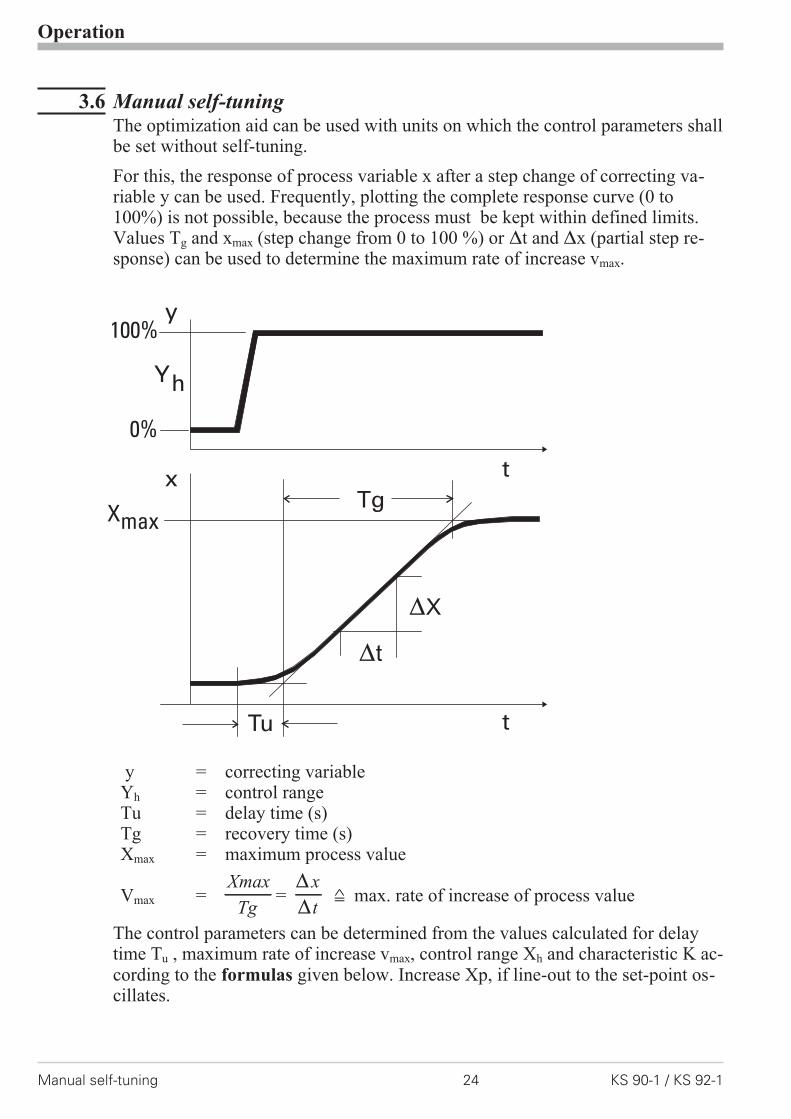
3.6 Manual self-tuningThe optimization aid can be used with units on which the control parameters shallbe set without self-tuning.
For this, the response of process variable x after a step change of correcting va-riable y can be used. Frequently, plotting the complete response curve (0 to100%) is not possible, because the process must be kept within defined limits.Values Tg and xmax (step change from 0 to 100 %) or �t and �x (partial step re-sponse) can be used to determine the maximum rate of increase vmax.
y = correcting variableYh = control rangeTu = delay time (s)Tg = recovery time (s)Xmax = maximum process value
Vmax =Xmax
Tg={
{
x
t= max. rate of increase of process value
The control parameters can be determined from the values calculated for delaytime Tu , maximum rate of increase vmax, control range Xh and characteristic K ac-cording to the formulas given below. Increase Xp, if line-out to the set-point os-cillates.
Operation
Manual self-tuning 24 KS 90-1 / KS 92-1
Tu
Tg
t
x
y100%
0%
t
Yh
Xmax
{X
{t

3.7 Second PID parameter setThe process characteristic is frequently affected by various factors such as pro-cess value, correcting variable and material differences.To comply with these requirements, KS 9x-1 can be switched over between twoparameter sets.Parameter sets PArA and PAr.2 are provided for heating and cooling.
Dependent of configuration ( ConF/LOG/Pid.2), switch-over to the second pa-rameter set ( ConF/LOG/Pid.2) is via one of digital inputs di1, di2, di3,key è or interface (OPTION).
g Self-tuning is always done using the active parameter set, i.e. the secondparameter set must be active for optimizing.
Operation
KS 90-1 / KS 92-1 25 Second PID parameter set
FormulasK = Vmax *Tu
controller behavior Pb1 [phy. units] td1 [s] ti1 [s]
With 2-point and 3-pointcontrollers, the cycle timemust be adjusted tot1 /t2 � 0,25 * Tu
PID 1,7 * K 2 * Tu 2 * TuPD 0,5 * K Tu OFF
PI 2,6 * K OFF 6 * TuP K OFF OFF
3-point-stepping 1,7 * K Tu 2 * Tu
Parameter adjustment effectsParameter Control Line-out of
disturbancesStart-up behaviour
Pb1 higher increased damping slower line-out slower reduction of duty cyclelower reduced damping faster line-out faster reduction of duty cycle
td1 higher reduced damping faster response todisturbances
faster reduction of duty cycle
lower increased damping slower response todisturbances
slower reduction of duty cycle
ti1 higher increased damping slower line-out slower reduction of duty cyclelower reduced damping faster line-out faster reduction of duty cycle

3.8 Alarm handlingMax. three alarms can be configured and assigned to the individual outputs. Ge-nerally, outputs OuT.1... OuT.6 can be used each for alarm signalling. If morethan one signal is linked to one output the signals are OR linked. Each of the 3 li-mit values Lim.1 … Lim.3 has 2 trigger points H.x (Max) and L.x (Min), whichcan be switched off individually (parameter = “OFF”). Switching differenceHYS.x and delay dEl.x of each limit value is adjustable.
1: normally closed ( ConF/Out.x /O.Act=1 ) (see examples in the drawing)2: normally open ( ConF/Out.x /O.Act=0 )(inverted output relay action)
Operation
Alarm handling 26 KS 90-1 / KS 92-1
H.1
LED
HYS.1
InL.1 InH.1
Ü Operaing principle absolut alarm
L.1 = OFF
LED
HYS.1
H.1
InL.1 InH.1
SP
* Operating principle relative alarm
L.1 = OFF
L.1
LED
HYS.1
InL.1 InH.1
H.1 = OFF
L.1
LED
HYS.1
InL.1 InH.1
SP
H.1 = OFF
L.1
LED LED
HYS.1 HYS.1
H.1
InL.1 InH.1
L.1
LED LED
HYS.1 HYS.1
H.1
InL.1 InH.1
SP
2 2
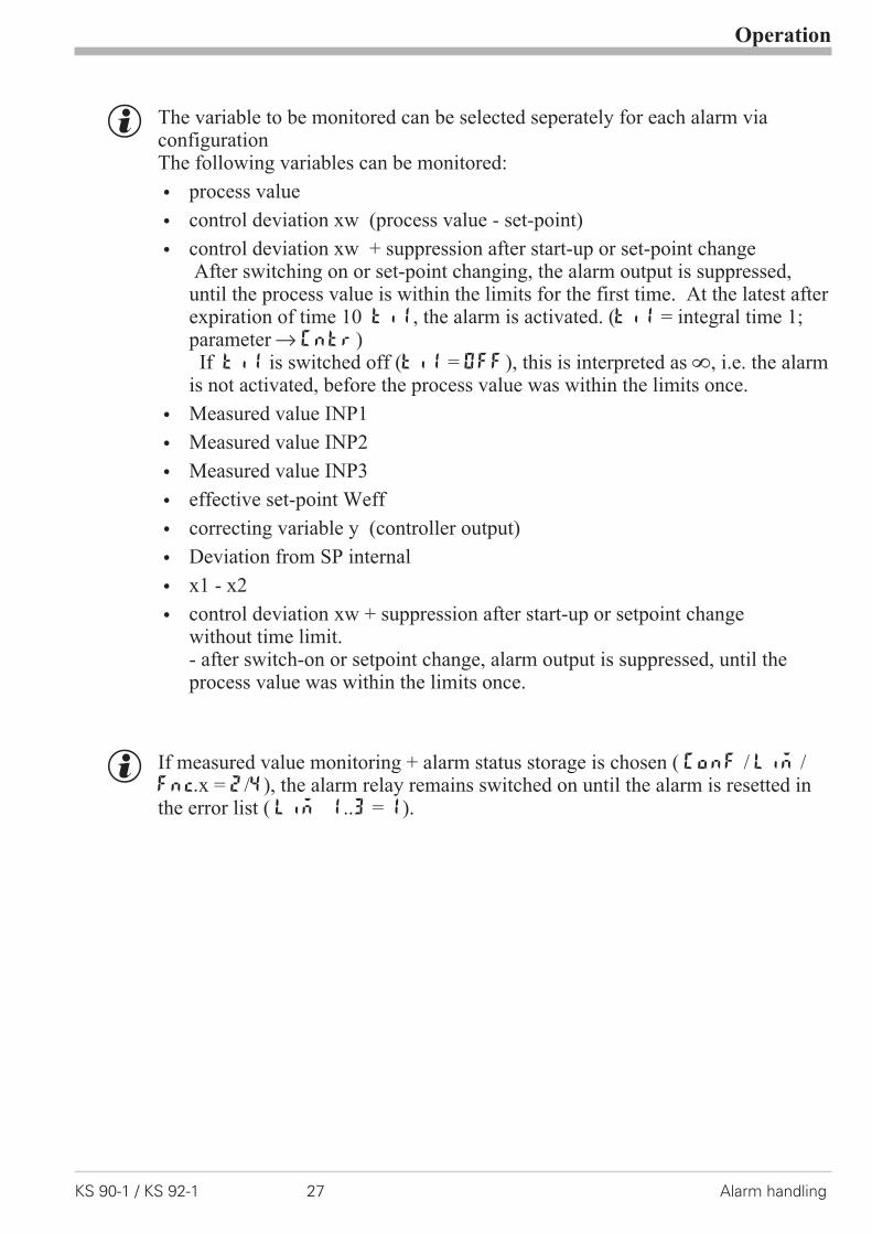
g The variable to be monitored can be selected seperately for each alarm viaconfigurationThe following variables can be monitored:
w process value
w control deviation xw (process value - set-point)
w control deviation xw + suppression after start-up or set-point changeAfter switching on or set-point changing, the alarm output is suppressed,until the process value is within the limits for the first time. At the latest afterexpiration of time 10 ti1, the alarm is activated. (ti1 = integral time 1;parameter r Cntr)If ti1 is switched off (ti1 = OFF), this is interpreted as Î, i.e. the alarm
is not activated, before the process value was within the limits once.
w Measured value INP1
w Measured value INP2
w Measured value INP3
w effective set-point Weff
w correcting variable y (controller output)
w Deviation from SP internal
w x1 - x2
w control deviation xw + suppression after start-up or setpoint changewithout time limit.- after switch-on or setpoint change, alarm output is suppressed, until theprocess value was within the limits once.
g If measured value monitoring + alarm status storage is chosen ( ConF / Lim /Fnc.x = 2/4), the alarm relay remains switched on until the alarm is resetted inthe error list ( Lim 1..3 = 1).
Operation
KS 90-1 / KS 92-1 27 Alarm handling
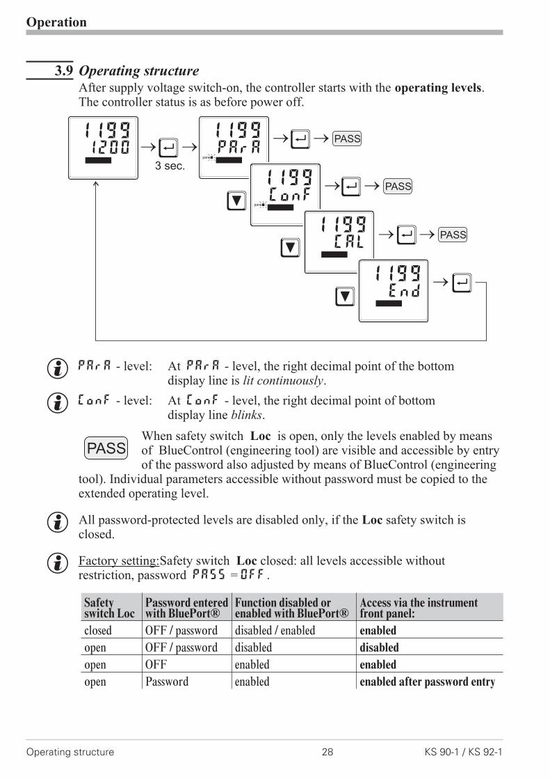
3.9 Operating structureAfter supply voltage switch-on, the controller starts with the operating levels.The controller status is as before power off.
g PArA - level: At PArA - level, the right decimal point of the bottomdisplay line is lit continuously.
g ConF - level: At ConF - level, the right decimal point of bottomdisplay line blinks.
When safety switch Loc is open, only the levels enabled by meansof BlueControl (engineering tool) are visible and accessible by entryof the password also adjusted by means of BlueControl (engineering
tool). Individual parameters accessible without password must be copied to theextended operating level.
g All password-protected levels are disabled only, if the Loc safety switch isclosed.
g Factory setting:Safety switch Loc closed: all levels accessible withoutrestriction, password PASS = OFF.
Safetyswitch Loc
Password enteredwith BluePort®
Function disabled orenabled with BluePort®
Access via the instrumentfront panel:
closed OFF / password disabled / enabled enabled
open OFF / password disabled disabled
open OFF enabled enabled
open Password enabled enabled after password entry
Operation
Operating structure 28 KS 90-1 / KS 92-1
Ù
Ù
Ù
Ù
Ù
Ì
Ì
Ì
3 sec.
PASS12001199
PArA1199
para
ConF1199
para
CAL1199
End1199
PASS
PASS
PASS
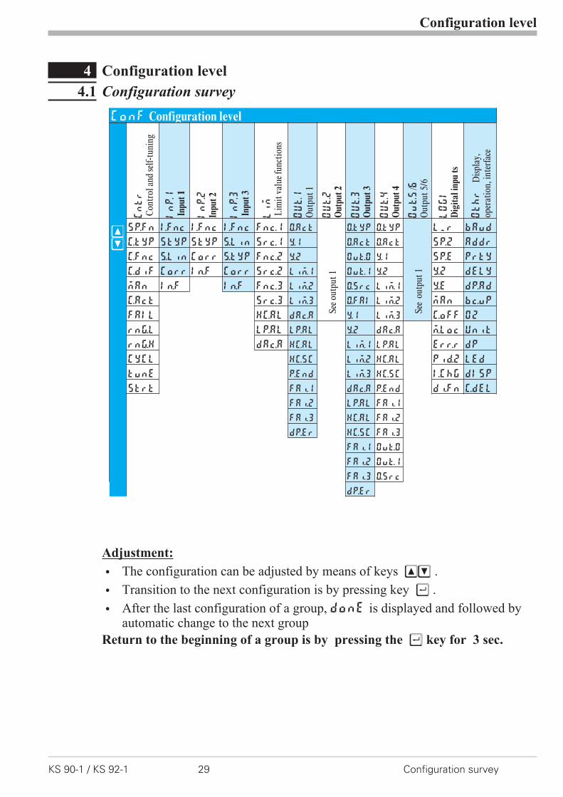
4 Configuration level
4.1 Configuration survey
Adjustment:
w The configuration can be adjusted by means of keys ÈÌ .
w Transition to the next configuration is by pressing key Ù .
w After the last configuration of a group, donE is displayed and followed byautomatic change to the next group
Return to the beginning of a group is by pressing the Ù key for 3 sec.
Configuration level
KS 90-1 / KS 92-1 29 Configuration survey
ConF Configuration level
ÈÌ
Cntr
Con
trol
and
self-
tuni
ng
InP.1
Inpu
t1
InP.2
Inpu
t2
InP.3
Inpu
t3
Lim
Lim
itva
luef
unct
ions
OUt.1
Out
put1
OUt.2
Out
put
2
OUt.3
Out
put
3
OUt.4
Out
put
4
Out.5
/6O
utpu
t5/6
LOGI
Dig
ital
inpu
ts
Othr
Disp
lay,
oper
atio
n,in
terf
ace
SP.Fn I.Fnc I.Fnc I.Fnc Fnc.1 O.Act
Seeo
utpu
t1
O.tYP O.tYP
See
outp
ut1
L_r bAud
C.tYP StYP StYP S.Lin Src.1 Y.1 O.Act O.Act SP.2 Addr
C.Fnc S.Lin Corr S.Typ Fnc.2 Y.2 OuT.0 Y.1 SP.E PrtY
C.dif Corr In.F Corr Src.2 Lim.1 Out.1 Y.2 Y.2 dELY
mAn In.F In.F Fnc.3 Lim.2 O.Src Lim.1 Y.E dp.Ad
C.Act Src.3 Lim.3 O.FAI Lim.2 mAn bc.up
FAIL HC.AL dAc.A Y.1 Lim.3 C.oFF O2
rnG.L LP.AL LP.AL Y.2 dAc.A m.Loc Unit
rnG.H dAc.A HC.AL Lim.1 LP.AL Err.r dP
CYCL HC.SC Lim.2 HC.AL Pid.2 LEd
tunE P.End Lim.3 HC.SC I.Chg dISP
Strt FAi.1 dAc.A P.End di.Fn C.dEl
FAi.2 LP.AL FAi.1
FAi.3 HC.AL FAi.2
dP.Er HC.SC FAi.3
FAi.1 OuT.0
FAi.2 Out.1
FAi.3 O.Src
dP.Er
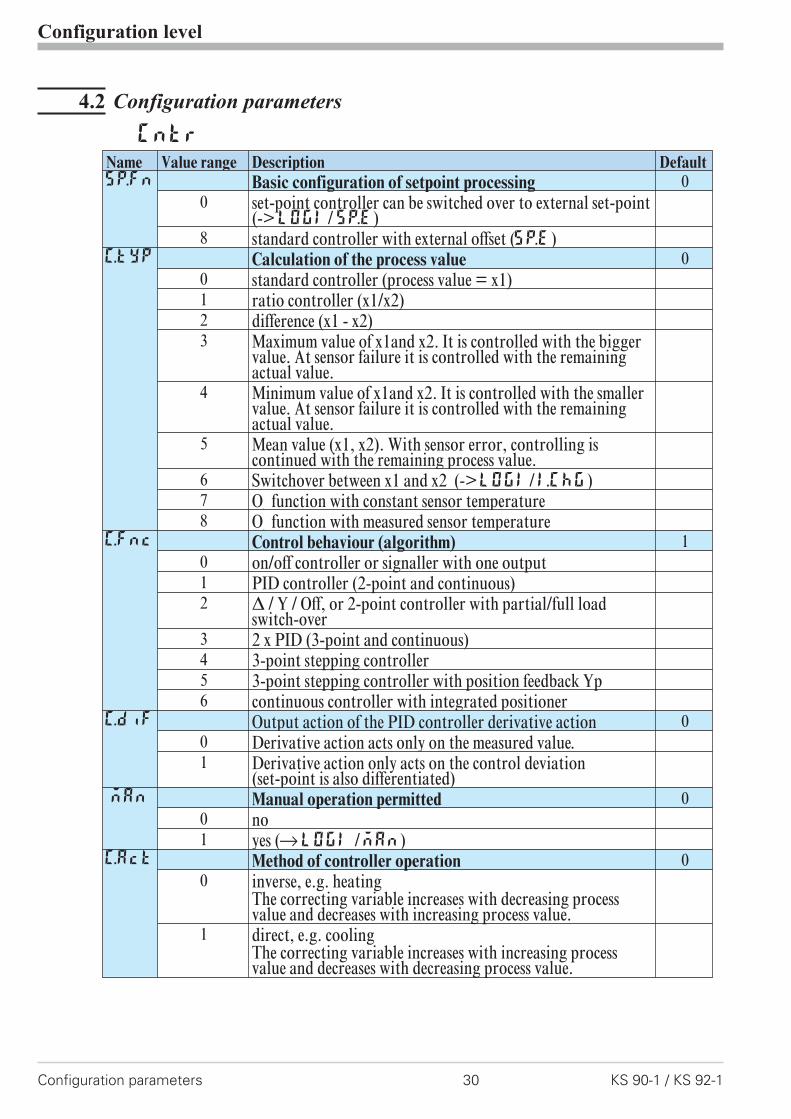
4.2 Configuration parameters
Configuration level
Configuration parameters 30 KS 90-1 / KS 92-1
Cntr
Name Value range Description DefaultSP.Fn Basic configuration of setpoint processing 0
0 set-point controller can be switched over to external set-point(->LOGI/SP.E)
8 standard controller with external offset (SP.E)C.tYP Calculation of the process value 0
0 standard controller (process value = x1)1 ratio controller (x1/x2)2 difference (x1 - x2)3 Maximum value of x1and x2. It is controlled with the bigger
value. At sensor failure it is controlled with the remainingactual value.
4 Minimum value of x1and x2. It is controlled with the smallervalue. At sensor failure it is controlled with the remainingactual value.
5 Mean value (x1, x2). With sensor error, controlling iscontinued with the remaining process value.
6 Switchover between x1 and x2 (->LOGI/I.ChG)7 O
2function with constant sensor temperature
8 O2
function with measured sensor temperatureC.Fnc Control behaviour (algorithm) 1
0 on/off controller or signaller with one output1 PID controller (2-point and continuous)2 � / Y / Off, or 2-point controller with partial/full load
switch-over3 2 x PID (3-point and continuous)4 3-point stepping controller5 3-point stepping controller with position feedback Yp6 continuous controller with integrated positioner
C.dif Output action of the PID controller derivative action 00 Derivative action acts only on the measured value.1 Derivative action only acts on the control deviation
(set-point is also differentiated)mAn Manual operation permitted 0
0 no1 yes (rLOGI /mAn)
C.Act Method of controller operation 00 inverse, e.g. heating
The correcting variable increases with decreasing processvalue and decreases with increasing process value.
1 direct, e.g. coolingThe correcting variable increases with increasing processvalue and decreases with decreasing process value.
Configuration level
KS 90-1 / KS 92-1 31 Configuration parameters
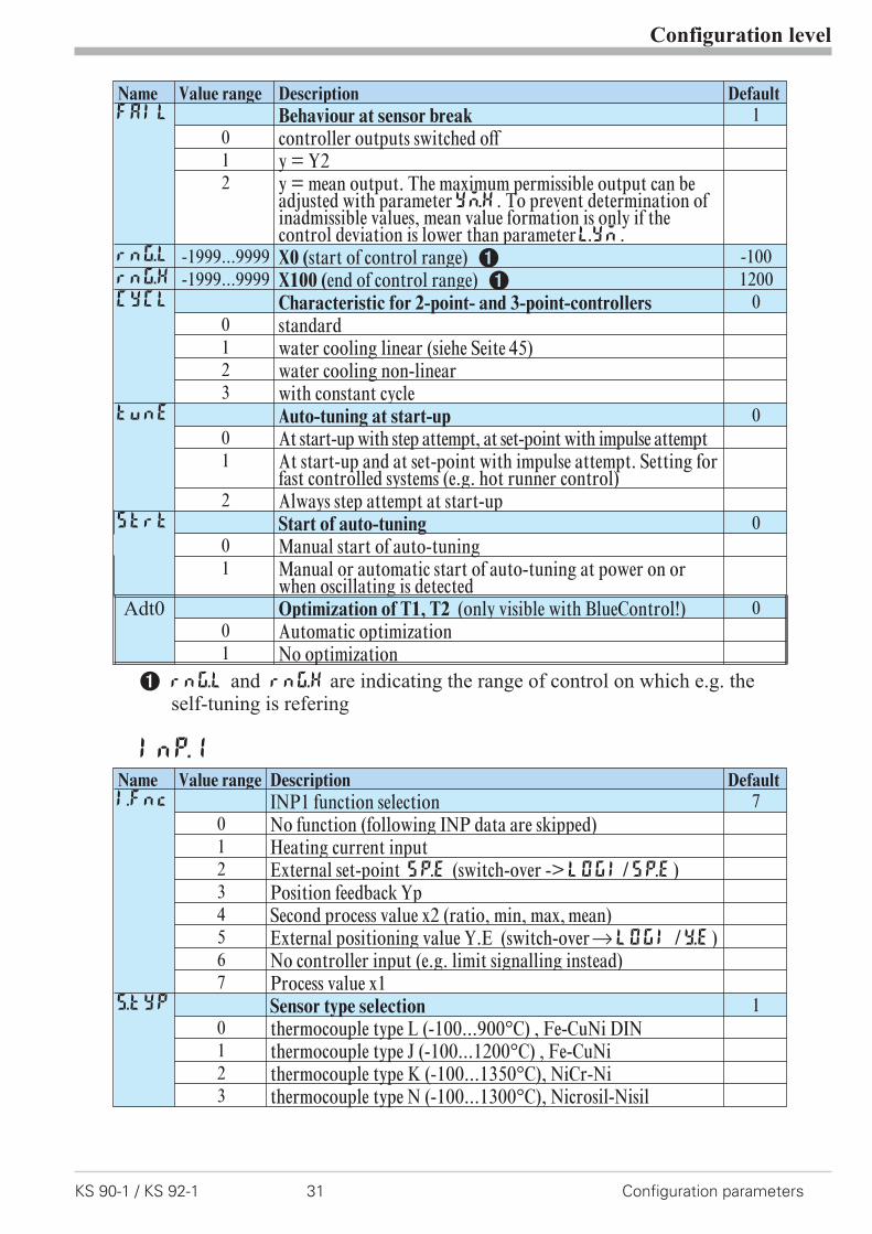
Name Value range Description DefaultFAIL Behaviour at sensor break 1
0 controller outputs switched off1 y = Y22 y = mean output. The maximum permissible output can be
adjusted with parameterYm.H. To prevent determination ofinadmissible values, mean value formation is only if thecontrol deviation is lower than parameterL.Ym.
rnG.L -1999...9999 X0 (start of control range) 1 -100rnG.H -1999...9999 X100 (end of control range) 1 1200CYCL Characteristic for 2-point- and 3-point-controllers 0
0 standard1 water cooling linear (siehe Seite 45)2 water cooling non-linear3 with constant cycle
tunE Auto-tuning at start-up 00 At start-up with step attempt, at set-point with impulse attempt1 At start-up and at set-point with impulse attempt. Setting for
fast controlled systems (e.g. hot runner control)2 Always step attempt at start-up
Strt Start of auto-tuning 00 Manual start of auto-tuning1 Manual or automatic start of auto-tuning at power on or
when oscillating is detectedAdt0 Optimization of T1, T2 (only visible with BlueControl!) 0
0 Automatic optimization1 No optimization
1 rnG.L and rnG.H are indicating the range of control on which e.g. theself-tuning is refering
InP.1
Name Value range Description DefaultI.fnc INP1 function selection 7
0 No function (following INP data are skipped)1 Heating current input2 External set-point SP.E (switch-over ->LOGI/SP.E)3 Position feedback Yp4 Second process value x2 (ratio, min, max, mean)5 External positioning value Y.E (switch-overrLOGI /Y.E)6 No controller input (e.g. limit signalling instead)7 Process value x1
S.tYP Sensor type selection 10 thermocouple type L (-100...900°C) , Fe-CuNi DIN1 thermocouple type J (-100...1200°C) , Fe-CuNi2 thermocouple type K (-100...1350°C), NiCr-Ni3 thermocouple type N (-100...1300°C), Nicrosil-Nisil
Configuration level
Configuration parameters 32 KS 90-1 / KS 92-1
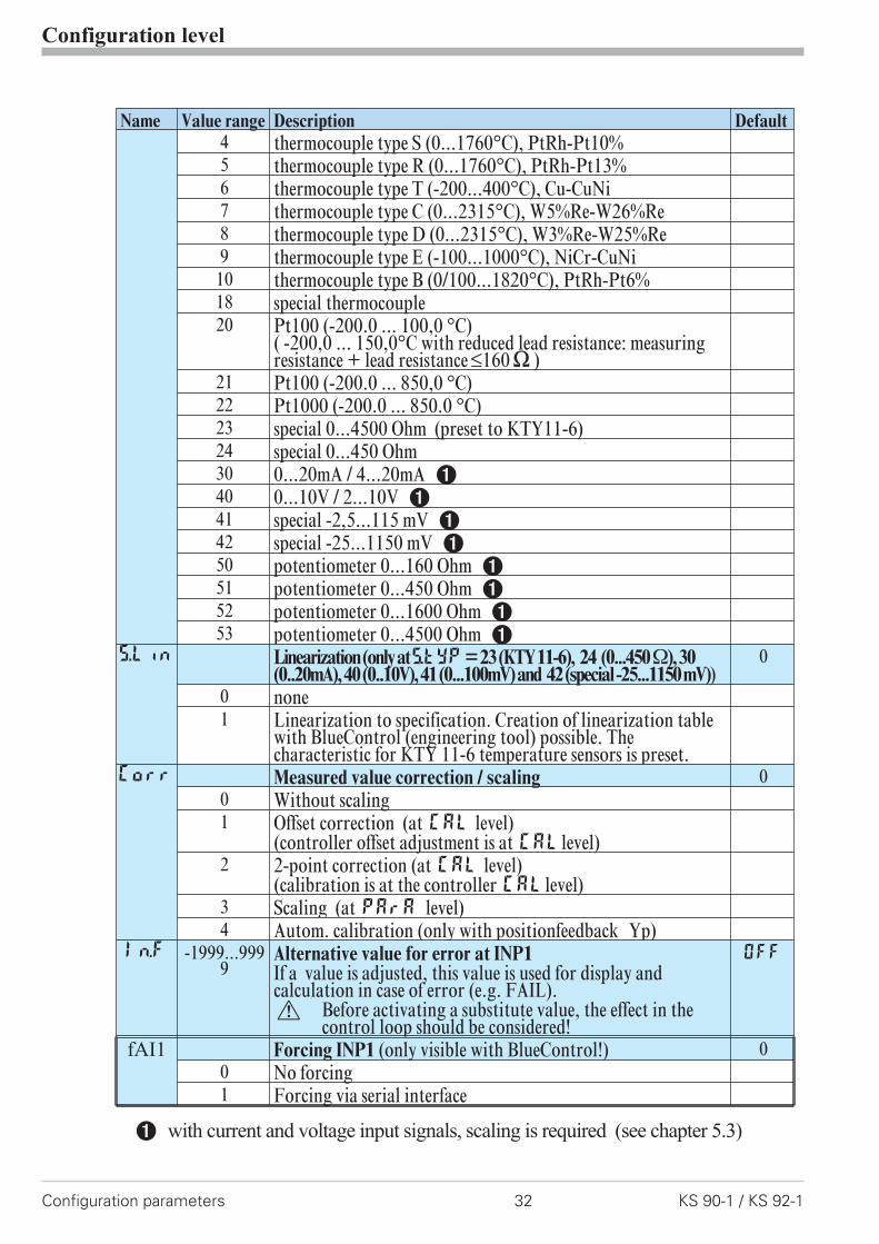
Name Value range Description Default4 thermocouple type S (0...1760°C), PtRh-Pt10%5 thermocouple type R (0...1760°C), PtRh-Pt13%6 thermocouple type T (-200...400°C), Cu-CuNi7 thermocouple type C (0...2315°C), W5%Re-W26%Re8 thermocouple type D (0...2315°C), W3%Re-W25%Re9 thermocouple type E (-100...1000°C), NiCr-CuNi
10 thermocouple type B (0/100...1820°C), PtRh-Pt6%18 special thermocouple20 Pt100 (-200.0 ... 100,0 °C)
( -200,0 ... 150,0°C with reduced lead resistance: measuringresistance + lead resistance ß160[ )
21 Pt100 (-200.0 ... 850,0 °C)22 Pt1000 (-200.0 ... 850.0 °C)23 special 0...4500 Ohm (preset to KTY11-6)24 special 0...450 Ohm30 0...20mA / 4...20mA 140 0...10V / 2...10V 141 special -2,5...115 mV 142 special -25...1150 mV 150 potentiometer 0...160 Ohm 151 potentiometer 0...450 Ohm 152 potentiometer 0...1600 Ohm 153 potentiometer 0...4500 Ohm 1
S.Lin Linearization(onlyatS.tYP=23(KTY11-6), 24 (0...450�),30(0..20mA),40(0..10V),41(0...100mV)and 42(special-25...1150mV))
0
0 none1 Linearization to specification. Creation of linearization table
with BlueControl (engineering tool) possible. Thecharacteristic for KTY 11-6 temperature sensors is preset.
Corr Measured value correction / scaling 00 Without scaling1 Offset correction (at CAL level)
(controller offset adjustment is at CALlevel)2 2-point correction (at CAL level)
(calibration is at the controller CALlevel)3 Scaling (at PArA level)4 Autom. calibration (only with positionfeedback Yp)
In.f -1999...9999
Alternative value for error at INP1If a value is adjusted, this value is used for display andcalculation in case of error (e.g. FAIL).a Before activating a substitute value, the effect in the
control loop should be considered!
OFF
fAI1 Forcing INP1 (only visible with BlueControl!) 00 No forcing1 Forcing via serial interface
1 with current and voltage input signals, scaling is required (see chapter 5.3)

Configuration level
KS 90-1 / KS 92-1 33 Configuration parameters
InP.2
Name Value range Description DefaultI.Fnc Function selection of INP2 1
0 no function (subsequent input data are skipped)1 heating current input2 external set-point (SP.E)3 Yp input4 Second process value X25 External positioning value Y.E (switch-overrLOGI /Y.E)6 no controller input (e.g. transmitter input instead)7 Process value x1
S.tYP Sensor type selection 3030 0...20mA / 4...20mA 131 0...50mA AC 150 Potentiometer ( 0...160 Ohm) 151 Potentiometer ( 0...450 Ohm) 152 Potentiometer ( 0...1600 Ohm) 153 Potentiometer ( 0...4500 Ohm) 1
Corr Measured value correction / scaling 00 Without scaling1 Offset correction (at CAL level)
(offset entry is at controller CALlevel)2 2-point correction (at CALlevel)
(calibration is at controller CALlevel)3 Scaling (at PArA level)
In.F -1999...9999
Alternative value for error at INP2If a value is adjusted, this value is used for display andcalculation in case of error (e.g. FAIL).a Before activating a substitute value, the effect in the
control loop should be considered!
OFF
fAI2 Forcing INP2 (only visible with BlueControl!) 00 No forcing1 Forcing via serial interface
1 with current and voltage input signals, scaling is required (see chapter 5.3)
InP.3
Name Value range Description DefaultI.Fnc Function selection of INP3 1
0 no function (subsequent input data are skipped)1 heating current input2 External set-point SP.E (switch-over ->LOGI/SP.E)3 Yp input4 Second process value X25 External positioning value Y.E (switch-overrLOGI /Y.E)6 no controller input (e.g. transmitter input instead)7 Process value x1

Configuration level
Configuration parameters 34 KS 90-1 / KS 92-1
Name Value range Description DefaultS.Lin Linearization (onlyatS.tYP=30(0..20mA)and40(0..10V)adjustable) 0
0 none1 Linearization to specification. Creation of linearization table
with BlueControl (engineering tool) possible. Thecharacteristic for KTY 11-6 temperature sensors is preset.
S.tYP Sensor type selection 300 thermocouple type L (-100...900°C) , Fe-CuNi DIN1 thermocouple type J (-100...1200°C) , Fe-CuNi2 thermocouple type K (-100...1350°C), NiCr-Ni3 thermocouple type N (-100...1300°C), Nicrosil-Nisil4 thermocouple type S (0...1760°C), PtRh-Pt10%5 thermocouple type R (0...1760°C), PtRh-Pt13%6 thermocouple type T (-200...400°C), Cu-CuNi7 thermocouple type C (0...2315°C), W5%Re-W26%Re8 thermocouple type D (0...2315°C), W3%Re-W25%Re9 thermocouple type E (-100...1000°C), NiCr-CuNi
10 thermocouple type B (0/100...1820°C), PtRh-Pt6%18 special thermocouple20 Pt100 (-200.0 ... 100,0 °C)
( -200,0 ... 150,0°C with reduced lead resistance: measuringresistance + lead resistance ß160[ )
21 Pt100 (-200.0 ... 850,0 °C)22 Pt1000 (-200.0 ... 850.0 °C)23 special 0...4500 Ohm (preset to KTY11-6)24 special 0...450 Ohm30 0...20mA / 4...20mA 141 special -2,5...115 mV 142 special -25...115 0mV 150 potentiometer 0...160 Ohm 151 potentiometer 0...450 Ohm 152 potentiometer 0...1600 Ohm 153 potentiometer 0...4500 Ohm 1
Corr Measured value correction / scaling 00 Without scaling1 Offset correction (at CAL level)
(offset entry is at controller CALlevel)2 2-point correction (at CAL level)
(calibration is at controller CALlevel)3 Scaling (at PArA level)4 Automatic calibration (DAC)
In.F -1999...9999
Alternative value for error at INP3If a value is adjusted, this value is used for display andcalculation in case of error (e.g. FAIL).a Before activating a substitute value, the effect in the
control loop should be considered!
OFF
fAI3 Forcing INP3 (only visible with BlueControl!) 00 No forcing1 Forcing via serial interface
1 with current and voltage input signals, scaling is required (see chapter 5.3)
Configuration level
KS 90-1 / KS 92-1 35 Configuration parameters
Lim
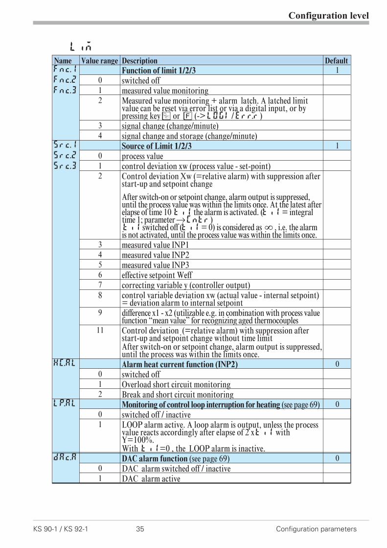
Name Value range Description DefaultFnc.1
Fnc.2
Fnc.3
Function of limit 1/2/3 10 switched off1 measured value monitoring2 Measured value monitoring + alarm latch. A latched limit
value can be reset via error list or via a digital input, or bypressing keyÒ or è (->LOGI/Err.r)
3 signal change (change/minute)4 signal change and storage (change/minute)
Src.1
Src.2
Src.3
Source of Limit 1/2/3 10 process value1 control deviation xw (process value - set-point)2 Control deviation Xw (=relative alarm) with suppression after
start-up and setpoint change
After switch-on or setpoint change, alarm output is suppressed,until the process value was within the limits once. At the latest afterelapse of time 10 ti1 the alarm is activated. (ti1= integraltime 1; parameterrCntr)ti1 switched off (ti1= 0) is considered as Î , i.e. the alarmis not activated, until the process value was within the limits once.
3 measured value INP14 measured value INP25 measured value INP36 effective setpoint Weff7 correcting variable y (controller output)8 control variable deviation xw (actual value - internal setpoint)
= deviation alarm to internal setpoint9 difference x1 - x2 (utilizable e.g. in combination with process value
function “mean value” for recognizing aged thermocouples11 Control deviation (=relative alarm) with suppression after
start-up and setpoint change without time limitAfter switch-on or setpoint change, alarm output is suppressed,until the process was within the limits once.
HC.AL Alarm heat current function (INP2) 00 switched off1 Overload short circuit monitoring2 Break and short circuit monitoring
LP.AL Monitoring of control loop interruption for heating (see page 69) 00 switched off / inactive1 LOOP alarm active. A loop alarm is output, unless the process
value reacts accordingly after elapse of 2 xti1 withY=100%.With ti1=0 , the LOOP alarm is inactive.
dAc.A DAC alarm function (see page 69) 00 DAC alarm switched off / inactive1 DAC alarm active
Configuration level
Configuration parameters 36 KS 90-1 / KS 92-1
Name Value range Description Default
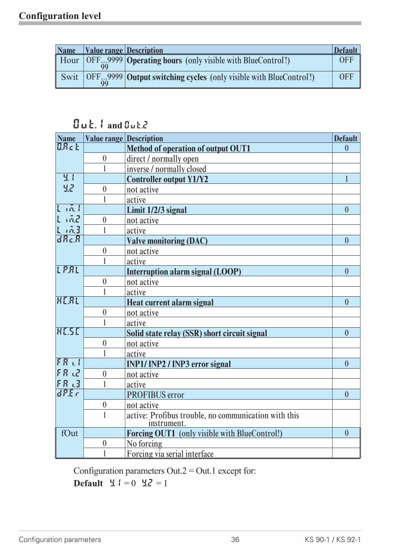
Hour OFF...999999
Operating hours (only visible with BlueControl�
!) OFF
Swit OFF...999999
Output switching cycles (only visible with BlueControl�
!) OFF
Out.1 and Out.2
Name Value range Description DefaultO.Act Method of operation of output OUT1 0
0 direct / normally open1 inverse / normally closed
Y.1
Y.2
Controller output Y1/Y2 10 not active1 active
Lim.1
Lim.2
Lim.3
Limit 1/2/3 signal 00 not active1 active
dAc.A Valve monitoring (DAC) 00 not active1 active
LP.AL Interruption alarm signal (LOOP) 00 not active1 active
HC.AL Heat current alarm signal 00 not active1 active
HC.SC Solid state relay (SSR) short circuit signal 00 not active1 active
FAi.1
FAi.2
FAi.3
INP1/ INP2 / INP3 error signal 00 not active1 active
dP.Er PROFIBUS error 00 not active1 active: Profibus trouble, no communication with this
instrument.fOut Forcing OUT1 (only visible with BlueControl!) 0
0 No forcing1 Forcing via serial interface
Configuration parameters Out.2 = Out.1 except for:
Default Y.1 = 0 Y.2 = 1

Configuration level
KS 90-1 / KS 92-1 37 Configuration parameters
Out.3 and Out4
Name Value range Description DefaultO.tYP Signal type selection OUT3 0
0 relay / logic (only visible with current/logic voltage)1 0 ... 20 mA continuous (only visible with current/logic/voltage)2 4 ... 20 mA continuous (only visible with current/logic/voltage)3 0...10 V continuous (only visible with current/logic/voltage)4 2...10 V continuous (only visible with current/logic/voltage)5 transmitter supply (only visible without OPTION)
O.Act MethodofoperationofoutputOUT3(onlyvisiblewhenO.TYP=0) 10 direct / normally open1 inverse / normally closed
Out.0 -1999...9999 Scaling of the analog output for 0% (0/4mA or 0/2V, onlyvisible when O.TYP=1..5)
0
Out.1 -1999...9999 Scaling of the analog output for 100% (20mA or 10V, onlyvisible when O.TYP=1..5)
100
O.Src Signal source of the analog output OUT3 (only visiblewhen O.TYP=1..5)
1
0 not used1 controller output y1 (continuous)2 controller output y2 (continuous)3 process value4 effective set-point Weff5 control deviation xw (process value - set-point)6 measured value position feedback Yp7 measured value INP18 measured value INP29 measured value INP3
O.FAI Failbehaviour, behaviour of the analog output, if the signalsource (O.Src) is disturbed.
0
0 upscale1 downscale
Y.1
Y.2
Controller output Y1/Y2 (only visible when O.TYP=0) 00 not active1 active
Lim.1
Lim.2
Lim.3
Limit 1/2/3 signal (only visible when O.TYP=0) 10 not active1 active
dAc.A Valve monitoring (DAC) (only visible when O.TYP=0) 00 not active1 active
LP.AL Interruption alarm signal (LOOP) (only visible whenO.TYP=0) (Loop-Alarm)
0
0 not active1 active

Configuration level
Configuration parameters 38 KS 90-1 / KS 92-1
Name Value range Description DefaultHC.AL Heating current alarm signal (only visible when O.TYP=0) 0
0 not active1 active
HC.SC Solid state relay (SSR) short circuit signal (only visible whenO.TYP=0)
0
0 not active1 active
FAi.1
FAi.2
FAi.3
INP1/ INP2 / INP3 error (only visible when O.TYP=0) 10 not active1 active
dP.Er PROFIBUS error 00 not active1 active: Profibus trouble, no communication with this
instrument.fOut Forcing OUT3 (only visible with BlueControl!) 0
0 No forcing1 Forcing via serial interface
Out.5/Out.6
Configuration parameters Out.2 = Out.1 except for: Default Y.1 = 0 Y.2 = 0
g Method of operation and usage of output Out.1 to Out.6:
Is more than one signal chosen active as source, those signals are OR-linked.
LOGI
Name Value range Description DefaultL_r Local / Remote switching (Remote: adjusting of all values by
front keys is blocked)0
0 no function (switch-over via interface is possible)1 always active2 DI1 switches3 DI2 switches (basic instrument or OPTION)4 DI3 switches (only visible with OPTION)5 è - key switches
SP.2 Switching to second setpointSP.2 00 no function (switch-over via interface is possible)2 DI1 switches3 DI2 switches (only visible with OPTION)4 DI3 switches (only visible with OPTION)5 è - key switches
Configuration level
KS 90-1 / KS 92-1 39 Configuration parameters
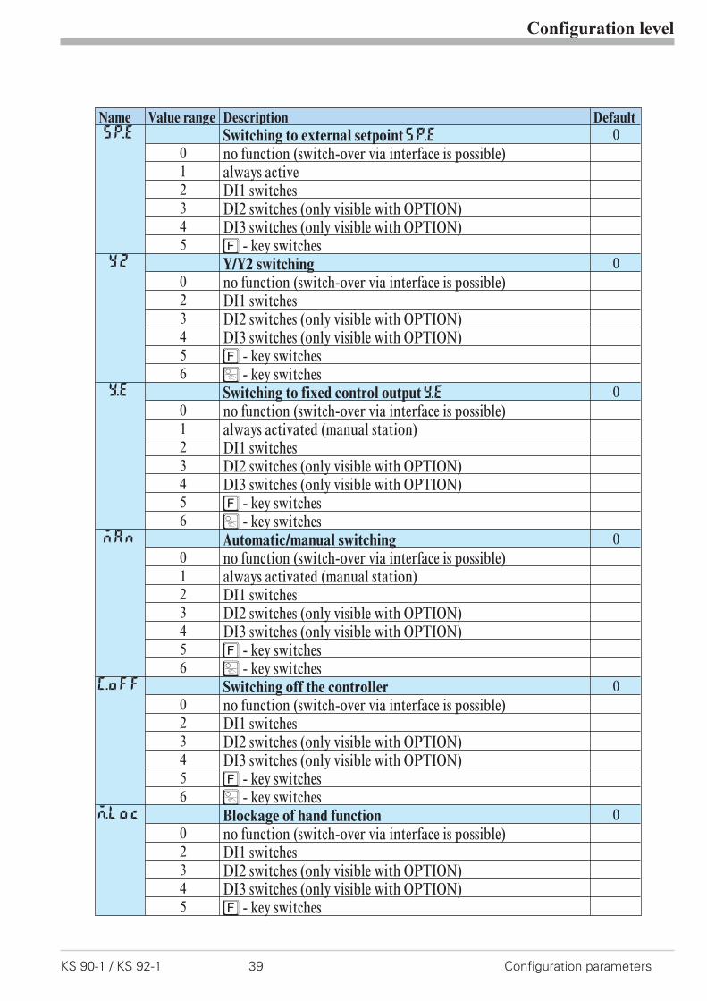
Name Value range Description DefaultSP.E Switching to external setpointSP.E 0
0 no function (switch-over via interface is possible)1 always active2 DI1 switches3 DI2 switches (only visible with OPTION)4 DI3 switches (only visible with OPTION)5 è - key switches
Y2 Y/Y2 switching 00 no function (switch-over via interface is possible)2 DI1 switches3 DI2 switches (only visible with OPTION)4 DI3 switches (only visible with OPTION)5 è - key switches6 Ò - key switches
Y.E Switching to fixed control outputY.E 00 no function (switch-over via interface is possible)1 always activated (manual station)2 DI1 switches3 DI2 switches (only visible with OPTION)4 DI3 switches (only visible with OPTION)5 è - key switches6 Ò - key switches
mAn Automatic/manual switching 00 no function (switch-over via interface is possible)1 always activated (manual station)2 DI1 switches3 DI2 switches (only visible with OPTION)4 DI3 switches (only visible with OPTION)5 è - key switches6 Ò - key switches
C.oFF Switching off the controller 00 no function (switch-over via interface is possible)2 DI1 switches3 DI2 switches (only visible with OPTION)4 DI3 switches (only visible with OPTION)5 è - key switches6 Ò - key switches
m.Loc Blockage of hand function 00 no function (switch-over via interface is possible)2 DI1 switches3 DI2 switches (only visible with OPTION)4 DI3 switches (only visible with OPTION)5 è - key switches

Configuration level
Configuration parameters 40 KS 90-1 / KS 92-1
Name Value range Description DefaultErr.r Reset of all error list entries 0
0 no function (switch-over via interface is possible)2 DI1 switches3 DI2 switches (only visible with OPTION)4 DI3 switches (only visible with OPTION)5 è - key switches6 Ò - key switches
Pid.2 Switching of parameter set (Pb, ti, td) 00 no function (switch-over via interface is possible)2 DI1 switches3 DI2 switches (only visible with OPTION)4 DI3 switches (only visible with OPTION)5 è - key switches
I.Chg Switching of the actual process value between Inp1 and X2 00 no function (switch-over via interface is possible)2 DI1 switches3 DI2 switches (only visible with OPTION)4 DI3 switches (only visible with OPTION)5 è - key switches
di.Fn Function of digital inputs (valid for all inputs) 00 direct1 inverse2 toggle key function
fDI1
fDI2
fDI3
Forcing di1/2/3 (only visible with BlueControl!) 00 No forcing1 Forcing via serial interface
othr
Name Value range Description DefaultbAud Baudrate of the interface (only visible with OPTION) 2
0 2400 Baud1 4800 Baud2 9600 Baud3 19200 Baud
Addr 1...247 Address on the interace (only visible with OPTION) 1PrtY Data parity on the interface (only visible with OPTION) 1
0 no parity (2 stop bits)1 even parity2 odd parity3 no parity (1 stopbit)
dELY 0...200 Delay of response signal [ms] (only visible with OPTION) 0
Configuration level
KS 90-1 / KS 92-1 41 Configuration parameters
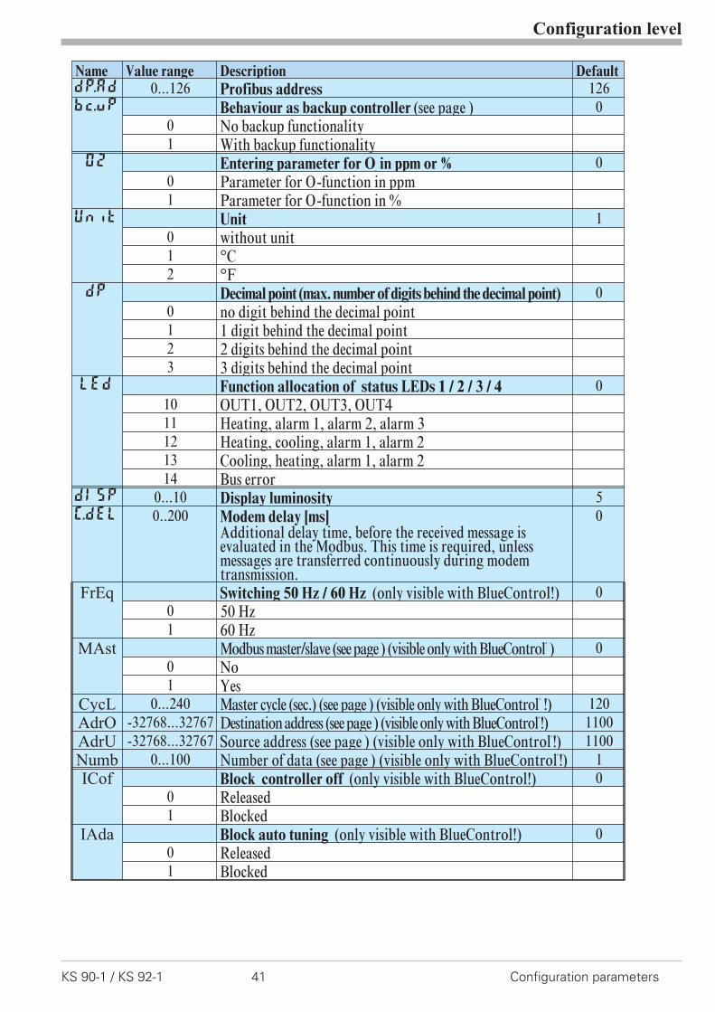
Name Value range Description DefaultdP.AD 0...126 Profibus address 126bc.up Behaviour as backup controller (see page ) 0
0 No backup functionality1 With backup functionality
O2 Entering parameter for O2
in ppm or % 00 Parameter for O
2-function in ppm
1 Parameter for O2-function in %
Unit Unit 10 without unit1 °C2 °F
dP Decimal point (max. number of digits behind the decimal point) 00 no digit behind the decimal point1 1 digit behind the decimal point2 2 digits behind the decimal point3 3 digits behind the decimal point
LED Function allocation of status LEDs 1 / 2 / 3 / 4 010 OUT1, OUT2, OUT3, OUT411 Heating, alarm 1, alarm 2, alarm 312 Heating, cooling, alarm 1, alarm 213 Cooling, heating, alarm 1, alarm 214 Bus error
dISP 0...10 Display luminosity 5C.dEl 0..200 Modem delay [ms]
Additional delay time, before the received message isevaluated in the Modbus. This time is required, unlessmessages are transferred continuously during modemtransmission.
0
FrEq Switching 50 Hz / 60 Hz (only visible with BlueControl!) 00 50 Hz1 60 Hz
MAst Modbus master/slave (see page ) (visible only with BlueControl®
) 00 No1 Yes
CycL 0...240 Master cycle (sec.) (see page ) (visible only with BlueControl®
!) 120AdrO -32768...32767 Destination address (see page ) (visible only with BlueControl
®
!) 1100AdrU -32768...32767 Source address (see page ) (visible only with BlueControl
®
!) 1100Numb 0...100 Number of data (see page ) (visible only with BlueControl
®
!) 1ICof Block controller off (only visible with BlueControl!) 0
0 Released1 Blocked
IAda Block auto tuning (only visible with BlueControl!) 00 Released1 Blocked
Configuration level
Configuration parameters 42 KS 90-1 / KS 92-1
Name Value range Description Default
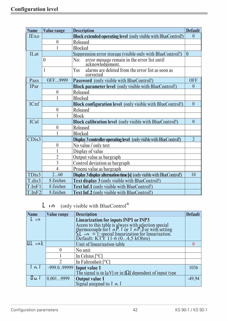
IExo Block extended operating level (only visible with BlueControl!) 00 Released1 Blocked
ILat Suppression error storage (visible only with BlueControl®
!) 00 No: error message remain in the error list until
acknowledgement.1 Yes alarms are deleted from the error list as soon as
correctedPass OFF...9999 Password (only visible with BlueControl!) OFFIPar Block parameter level (only visible with BlueControl!) 0
0 Released1 Blocked
ICnf Block configuration level (only visible with BlueControl!) 00 Released1 Block
ICal Block calibration level (only visible with BlueControl!) 00 Released1 Blocked
CDis3 Display3controlleroperatinglevel (onlyvisiblewithBlueControl!) 20 No value / only text1 Display of value2 Output value as bargraph3 Control deviation as bargraph4 Process value as bargraph
TDis3 2...60 Display3displayalternationtime[s] (onlyvisiblewithBlueControl!) 10T.dis3 8 Zeichen Text display 3 (only visible with BlueControl!)T.InF1 8 Zeichen Text Inf.1 (only visible with BlueControl!)T.InF2 8 Zeichen Text Inf.2 (only visible with BlueControl!)
Lin (only visible with BlueControl�
Name Value range Description DefaultLin Linearization for inputs INP1 or INP3
Access to this table is always with selection specialthermocouple forInP.1 or InP.3or with settingS.Lin = 1: special linearization for linearization.Default: KTY 11-6 (0...4,5 kOhm)
U.LinT Unit of linearization table 00 No unit1 In Celsius [°C]2 In Fahrenheit [°C]
In.1 -999.0..99999 Input value 1The signal is in [µV] or in [[] dependent of input type
1036
Ou.1 0,001...9999 Output value 1Signal assigned to In.1
-49,94
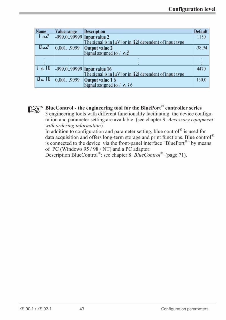
+ BlueControl - the engineering tool for the BluePort�
controller series3 engineering tools with different functionality facilitating the device configu-ration and parameter setting are available (see chapter 9: Accessory equipmentwith ordering information).In addition to configuration and parameter setting, blue control� is used fordata acquisition and offers long-term storage and print functions. Blue control�
is connected to the device via the front-panel interface "BluePort�" by meansof PC (Windows 95 / 98 / NT) and a PC adaptor.Description BlueControl�: see chapter 8: BlueControl� (page 71).
Configuration level
KS 90-1 / KS 92-1 43 Configuration parameters
Name Value range Description DefaultIn.2 -999.0..99999 Input value 2
The signal is in [µV] or in [[] dependent of input type1150
Ou.2 0,001...9999 Output value 2Signal assigned to In.2
-38,94
::
::
::
::
In.16 -999.0..99999 Input value 16The signal is in [µV] or in [[] dependent of input type
4470
Ou.16 0,001...9999 Output value 1 6Signal assigned to In.16
150,0
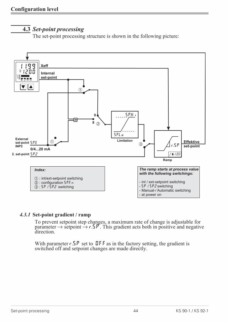
4.3 Set-point processingThe set-point processing structure is shown in the following picture:
4.3.1 Set-point gradient / ramp
To prevent setpoint step changes, a maximum rate of change is adjustable forparameter r setpoint r r.SP. This gradient acts both in positive and negativedirection.
With parameter r.SP set to OFFas in the factory setting, the gradient isswitched off and setpoint changes are made directly.
Configuration level
Set-point processing 44 KS 90-1 / KS 92-1
0
Ü
Xeff
SP.2
SP.E
0/4...20 mA
Internalset-point
*
Ö
SP.Hi
SP.Lo
r.SP
- LED
Externalset-pointINP2
Limitation
Ramp
2. set-point
Effektiveset-point
Ü
+8
The ramp starts at process valuewith the following switchings:
- int / ext-setpoint switching- / switching- Manual-/ Automatic switching- at power on
SP SP.2
Index:
Ü*Ö
: int/ext-setpoint switching: configuration: / switching
SP.Fn
SP SP.2
12001199°C°F
SP.2SP.E
parafuncAda
Err

4.4 Switching behaviuorWith these controllers, configuration parameter CYCL (ConF/ Cntr/ CYCL)can be used for matching the cycle time of 2-point and 3-point controllers. Thiscan be done using the following 4 methods.
4.4.1 Standard ( CyCl= 0 )
The adjusted cycle times t1 and t2 are valid for 50% or -50% correcting varia-ble. With very small or very high values, the effective cycle time is extended toprevent unreasonably short on and off pulses. The shortest pulses result from ¼x t1 or ¼ x t2. The characteristic curve is also called “bath tub curve”
Parameters to be adjusted: t1 : min. cycle time 1 (heating) [s]( PArA/ Cntr) t2 : min. cycle time 2 (cooling) [s]
4.4.2 Switching attitude linear ( CyCl= 1 )
For heating (Y1), the standard method (see chapter 4.4.1) is used. For cooling(Y2), a special algorithm for cooling with water is used. Generally, cooling is en-abled only at an adjustable process temperature (E.H2O), because low temperatu-res prevent evaporation with related cooling, whereby damage to the plant isavoided. The cooling pulse length is adjustable using parameter t.on and is fi-xed for all output values.The “off” time is varied dependent of output value. Parameter t.off is used fordetermining the min “off” time. For output of a shorter off pulse, this pulse issuppressed, i.e. the max. effective cooling output value is calculated according toformula t.on / ( t.on + t.off) w 100%.
Parameters to be adjusted: E.H2O: minimum temperature for water cooling( PArA / Cntr) t.on: pulse duration water cooling
t.off: minimum pause water cooling
Configuration level
KS 90-1 / KS 92-1 45 Switching behaviuor
0,0
1,0
2,0
3,0
4,0
5,0
6,0
5 10 15 20 25 30 35 40 45 50 55 60 65 70 75 80 85 90 95
Controller output [%]
rela
tive
cycle
du
rati
on
T / T1
t1
2 x t1
3 x t1
4 x t1
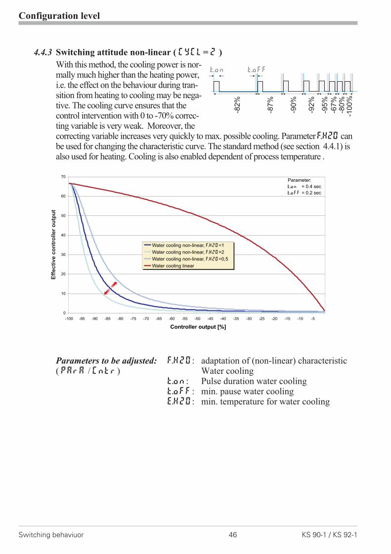
4.4.3 Switching attitude non-linear ( CyCl= 2 )
With this method, the cooling power is nor-mally much higher than the heating power,i.e. the effect on the behaviour during tran-sition from heating to cooling may be nega-tive. The cooling curve ensures that thecontrol intervention with 0 to -70% correc-ting variable is very weak. Moreover, thecorrecting variable increases very quickly to max. possible cooling. ParameterF.H2Ocanbe used for changing the characteristic curve. The standard method (see section 4.4.1) isalso used for heating. Cooling is also enabled dependent of process temperature .
Parameters to be adjusted: F.H2O: adaptation of (non-linear) characteristic( PArA / Cntr) Water cooling
t.on: Pulse duration water coolingt.off: min. pause water coolingE.H2O: min. temperature for water cooling
Configuration level
Switching behaviuor 46 KS 90-1 / KS 92-1
-95
%
-67
%-8
0%
-10
0%
-92
%
-90
%
-87
%
-82
%
t.offt.on
0
10
20
30
40
50
60
70
-100 -95 -90 -85 -80 -75 -70 -65 -60 -55 -50 -45 -40 -35 -30 -25 -20 -15 -10 -5
Controller output [%]
Water cooling non-linear, =1F.H2O
Water cooling non-linear, =2F.H2O
Water cooling non-linear, =0,5F.H2O
Water cooling linear
Parameter:
t.on = 0.4 sec
t.off = 0.2 sec
Eff
ecti
ve
co
ntr
oller
ou
tpu
t

4.4.4 Heating and cooling with constant period ( CyCl= 3 )
1 and t2 are met in the overall outputrange . To prevent unreasonably shortpulses, parameter tp is used for adju-sting the shortest pulse duration. Withsmall correcting values which require apulse shorter than the value adjusted intp, this pulse is suppressed. However,the controller stores the pulse and totali-zes further pulses, until a pulse of dura-tion tp can be output.
Parameters to be adjusted: t1 : Min. cycle time 1 (heating) [s]( PArA/ Cntr) t2 : min. cycle time 2 (cooling) [s]
tp: min. pulse length [s]
Configuration level
KS 90-1 / KS 92-1 47 Switching behaviuor
50%
50%
t1 t2/
tp
tp
30%
70%
20%
80%
10%
90%
t1 t2/
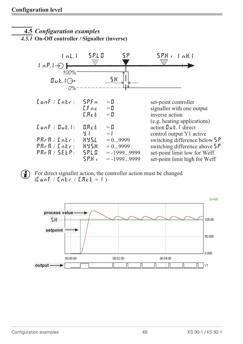
4.5 Configuration examples4.5.1 On-Off controller / Signaller (inverse)
ConF / Cntr: SP.Fn = 0 set-point controllerC.Fnc = 0 signaller with one outputC.Act = 0 inverse action
(e.g. heating applications)ConF / Out.1: O.Act = 0 action Out.1 direct
Y.1 =1 control output Y1 activePArA / Cntr: Hys.l = 0...9999 switching difference below SP
PArA / Cntr: Hys.H = 0...9999 switching difference above SPPArA / SEtP: SP.LO = -1999...9999 set-point limit low for Weff
SP.Hi = -1999...9999 set-point limit high for Weff
g For direct signaller action, the controller action must be changed(ConF / Cntr / C.Act = 1 )
Configuration level
Configuration examples 48 KS 90-1 / KS 92-1
InH.1InL.1 SP.LO SP SP.Hi
100%
0%
SHOut.1Â
InP.1Ê
setpoint
output
process value
SH
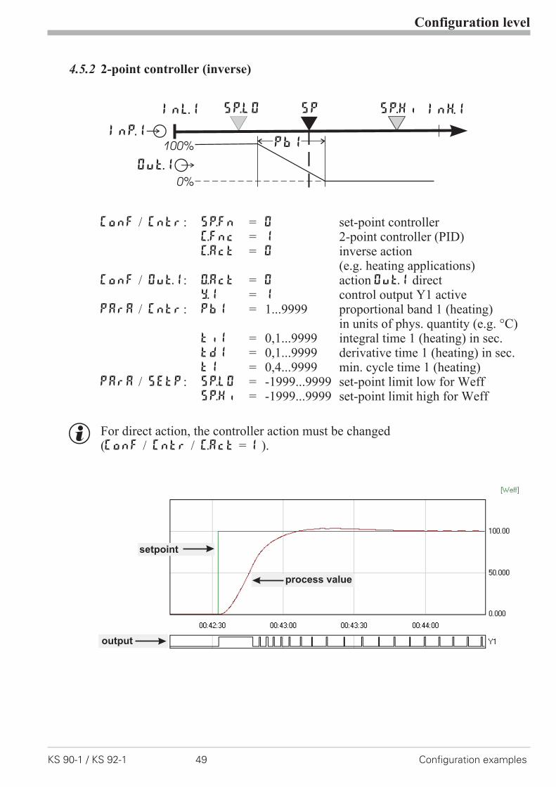
4.5.2 2-point controller (inverse)
ConF / Cntr: SP.Fn = 0 set-point controllerC.Fnc = 1 2-point controller (PID)C.Act = 0 inverse action
(e.g. heating applications)ConF / Out.1: O.Act = 0 action Out.1 direct
Y.1 = 1 control output Y1 activePArA / Cntr: Pb1 = 1...9999 proportional band 1 (heating)
in units of phys. quantity (e.g. °C)ti1 = 0,1...9999 integral time 1 (heating) in sec.td1 = 0,1...9999 derivative time 1 (heating) in sec.t1 = 0,4...9999 min. cycle time 1 (heating)
PArA / SEtP: SP.LO = -1999...9999 set-point limit low for WeffSP.Hi = -1999...9999 set-point limit high for Weff
g For direct action, the controller action must be changed(ConF / Cntr / C.Act = 1 ).
Configuration level
KS 90-1 / KS 92-1 49 Configuration examples
InH.1InL.1 SP.LO SP SP.Hi
Out.1Â
InP.1Ê100%
0%
PB1
setpoint
output
process value

4.5.3 3-point controller (relay & relay)
ConF / Cntr: SP.Fn = 0 set-point controllerC.Fnc = 3 3-point controller (2xPID)C.Act = 0 action inverse
(e.g. heating applications)ConF / Out.1: O.Act = 0 action Out.1 direct
Y.1 = 1 control output Y1 activeY.2 = 0 control output Y2 not active
ConF / Out.2: O.Act = 0 action Out.2 directY.1 = 0 control output Y1 not activeY.2 = 1 control output Y2 active
PArA / Cntr: Pb1 = 1...9999 proportional band 1 (heating)in units of phys. quantity (e.g. °C)
Pb2 = 1...9999 proportional band 2 (cooling)in units of phys. quantity (e.g. °C)
ti1 = 0,1...9999 integral time 1 (heating) in sec.ti2 = 0,1...9999 derivative time 2 (cooling) in sec.td1 = 0,1...9999 integral time 1 (heating) in sec.td2 = 0,1...9999 derivative time 2 (cooling) in sec.t1 = 0,4...9999 min. cycle time 1 (heating)t2 = 0,4...9999 min. cycle time 2 (cooling)SH = 0...9999 neutr. zone in units of phys.quantity
PArA / SEtP: SP.LO = -1999...9999 set-point limit low for WeffSP.Hi = -1999...9999 set-point limit high for Weff
Configuration level
Configuration examples 50 KS 90-1 / KS 92-1
InH.1InL.1 SP.LO SP SP.Hi
Out.1Â
InP.1Ê100%
0%
100%
0%
PB1 PB2
Out.2Â

4.5.4 3-point stepping controller (relay & relay)
ConF / Cntr: SP.Fn = 0 set-point controllerC.Fnc = 4 3-point stepping controllerC.Act = 0 inverse action
(e.g. heating applications)ConF / Out.1: O.Act = 0 action Out.1 direct
Y.1 = 1 control output Y1 activeY.2 = 0 control output Y2 not active
ConF / Out.2: O.Act = 0 action Out.2 directY.1 = 0 control output Y1 not activeY.2 = 1 control output Y2 active
PArA / Cntr: Pb1 = 1...9999 proportional band 1 (heating)in units of phys. quantity (e.g. °C)
ti1 = 0,1...9999 integral time 1 (heating) in sec.td1 = 0,1...9999 derivative time 1 (heating) in sec.t1 = 0,4...9999 min. cycle time 1 (heating)SH = 0...9999 neutral zone in units of phy. quantitytP = 0,1...9999 min. pulse length in sec.tt = 3...9999 actuator travel time in sec.
PArA / SEtP: SP.LO = -1999...9999 set-point limit low for WeffSP.Hi = -1999...9999 set-point limit high for Weff
g For direct action of the 3-point stepping controller, the controller output actionmust be changed ( ConF / Cntr / C.Act = 1 ).
Configuration level
KS 90-1 / KS 92-1 51 Configuration examples
InH.1InL.1 SP.LO SP SP.Hi
Out.1Â
InP.1Ê
Out.2Â
100%
0%
100%
0%
PB1
SH
setpoint
output 1
process value
output 2

4.5.5 Continuous controller (inverse)
ConF / Cntr: SP.Fn = 0 set-point controllerC.Fnc = 1 continuous controller (PID)C.Act = 0 inverse action
(e.g. heating applications)ConF / Out.3: O.tYP = 1 / 2 Out.3 type ( 0/4 … 20mA )
Out.0 = -1999...9999 scaling analog output 0/4mAOut.1 = -1999...9999 scaling analog output 20mA
PArA / Cntr: Pb1 = 1...9999 proportional band 1 (heating)in units of phys. quantity (e.g. °C)
ti1 = 0,1...9999 integral time 1 (heating) in sec.td1 = 0,1...9999 derivative time 1 (heating) in sec.t1 = 0,4...9999 min. cycle time 1 (heating)
PArA / SEtP: SP.LO = -1999...9999 set-point limit low for WeffSP.Hi = -1999...9999 set-point limit high for Weff
g For direct action of the continuous controller, the controller action must bechanged ( ConF / Cntr / C.Act = 1 ).
g To prevent control outputs Out.1 and Out.2 of the continuous controller fromswitching simultaneously, the control function of outputs Out.1 and Out.2
must be switched off ( ConF / Out.1 and Out.2 / Y.1 and Y.2 = 0 ).
Configuration level
Configuration examples 52 KS 90-1 / KS 92-1
InH.1InL.1 SP.LO SP SP.Hi
Out.3Â
InP.1Ê
20 mA
0/4 mA
PB1
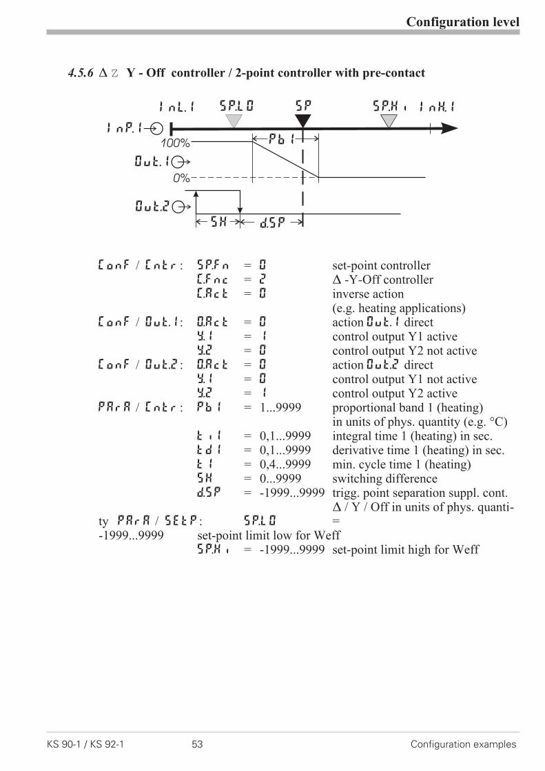
4.5.6 � � Y - Off controller / 2-point controller with pre-contact
ConF / Cntr: SP.Fn = 0 set-point controllerC.Fnc = 2 � -Y-Off controllerC.Act = 0 inverse action
(e.g. heating applications)ConF / Out.1: O.Act = 0 action Out.1 direct
Y.1 = 1 control output Y1 activeY.2 = 0 control output Y2 not active
ConF / Out.2: O.Act = 0 action Out.2 directY.1 = 0 control output Y1 not activeY.2 = 1 control output Y2 active
PArA / Cntr: Pb1 = 1...9999 proportional band 1 (heating)in units of phys. quantity (e.g. °C)
ti1 = 0,1...9999 integral time 1 (heating) in sec.td1 = 0,1...9999 derivative time 1 (heating) in sec.t1 = 0,4...9999 min. cycle time 1 (heating)SH = 0...9999 switching differenced.SP = -1999...9999 trigg. point separation suppl. cont.
� / Y / Off in units of phys. quanti-ty PArA / SEtP: SP.LO =-1999...9999 set-point limit low for Weff
SP.Hi = -1999...9999 set-point limit high for Weff
Configuration level
KS 90-1 / KS 92-1 53 Configuration examples
InH.1InL.1 SP.LO SP SP.Hi
Out.1Â
InP.1Ê100%
0%
PB1
Out.2Â
d.SPSH
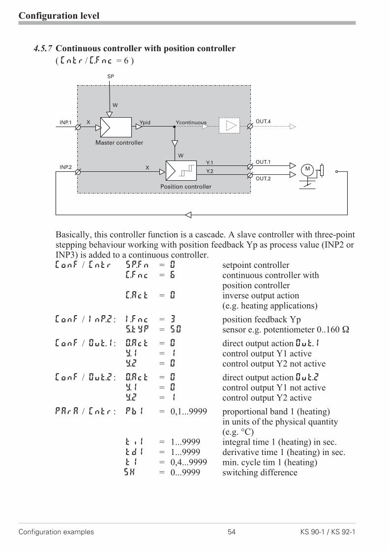
4.5.7 Continuous controller with position controller
( Cntr/ C.Fnc = 6 )
Basically, this controller function is a cascade. A slave controller with three-pointstepping behaviour working with position feedback Yp as process value (INP2 orINP3) is added to a continuous controller.ConF / Cntr SP.Fn = 0 setpoint controller
C.Fnc = 6 continuous controller withposition controller
C.Act = 0 inverse output action(e.g. heating applications)
ConF / InP.2: I.Fnc = 3 position feedback YpS.typ = 50 sensor e.g. potentiometer 0..160 �
ConF / Out.1: O.Act = 0 direct output action Out.1Y.1 = 1 control output Y1 activeY.2 = 0 control output Y2 not active
ConF / Out.2: O.Act = 0 direct output action Out.2Y.1 = 0 control output Y1 not activeY.2 = 1 control output Y2 active
PArA / Cntr: Pb1 = 0,1...9999 proportional band 1 (heating)in units of the physical quantity(e.g. °C)
ti1 = 1...9999 integral time 1 (heating) in sec.td1 = 1...9999 derivative time 1 (heating) in sec.t1 = 0,4...9999 min. cycle tim 1 (heating)SH = 0...9999 switching difference
Configuration level
Configuration examples 54 KS 90-1 / KS 92-1
W
X M
OUT.4
OUT.1
OUT.2
INP.2
Ypid
Position controller
INP.1
Y.1
Y.2
Master controller
YcontinuousX
W
SP

4.5.8 Measured value output
ConF / Out.3 / 4: O.tYP = 1 Out.3/ 4 0...20mA continuous= 2 Out.3/ 4 4...20mA continuous= 3 Out.3/ 4 0...10V continuous= 4 Out.3/ 4 2...10V continuous
Out.0 = -1999...9999 scaling Out.3/ 4for 0/4mA or 0/2V
Out.1 = -1999...9999 scaling Out.3/ 4for 20mA or 10V
O.Src = 3 signal source for Out.3/ 4 isthe process value
Configuration level
KS 90-1 / KS 92-1 55 Configuration examples
phys.quantity
mA / Vphys. quantity
Out.1
Out.0
0/4mA0/2V
20mA10V
1
456
789
10
1
2
3
4
5
6
7
8
9
10
11
12
13
14
17
(16)
+
L
N2
3
}90...250VAC24VUC
U
U
11
12
13
14
15
OUT3
OUT4INP1
15

5 Parameter setting level
5.1 Parameter survey
Adjustment:
w The parameters can be adjusted by means of keys ÈÌ
w Transition to the next parameter is by pressing key Ù
w After the last parameter of a group, donE is displayed, followed byautomatic change to the next group.
Parameter setting level
Parameter survey 56 KS 90-1 / KS 92-1
PArA Parameter setting level
È
Ì
Cntr
Con
trol
and
self
-tun
ing
PAr.2
2.se
tof
para
met
ers
SEtP
Set-
poin
tan
dpr
oces
sva
lue
InP.1
Inpu
t1
InP.2
Inpu
t2
InP.3
Inpu
t3
Lim
Lim
itva
lue
func
tion
s
End
Pb1 Pb12 SP.Lo InL.1 Inl.2 InL.3 L.1
Pb2 Pb22 SP.Hi OuL.1 OuL.2 OuL.3 H.1
ti1 ti12 SP.2 InH.1 InH.2 InH.3 HYS.1
ti2 ti22 r.SP OuH.1 OuH.2 OuH.3 dEl.1
td1 td12 tF.1 tF.2 tF.3 L.2
td2 td22 E.tc E.tc H.2
t1 HYS.2
t2 dEl.2
SH L.3
Hys.l H.3
Hys.H HYS.3
d.SP dEl.3
tP HC.A
tt
Y.Lo
Y.Hi
Y2
Y0
Ym.H
L.Ym
E.H2O
t.on
t.off
FH2
oFFS
tEmp
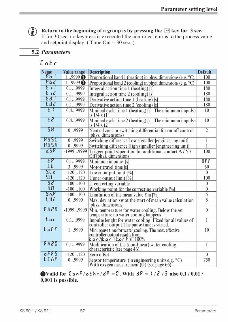
g Return to the beginning of a group is by pressing the Ù key for 3 sec.If for 30 sec. no keypress is excecuted the controler returns to the process valueand setpoint display ( Time Out = 30 sec. )
5.2 Parameters
Parameter setting level
KS 90-1 / KS 92-1 57 Parameters
Cntr
Name Value range Description DefaultPb1 1...99991 Proportional band 1 (heating) in phys. dimensions (e.g. °C) 100Pb2 1...99991 Proportional band 2 (cooling) in phys. dimensions (e.g. °C) 100ti1 0,1...9999 Integral action time 1 (heating) [s] 180ti2 0,1...9999 Integral action time 2 (cooling) [s] 180td1 0,1...9999 Derivative action time 1 (heating) [s] 180td2 0,1...9999 Derivative action time 2 (cooling) [s] 180t1 0,4...9999 Minimal cycle time 1 (heating) [s]. The minimum impulse
is 1/4 x t110
t2 0,4...9999 Minimal cycle time 2 (heating) [s]. The minimum impulseis 1/4 x t2
10
SH 0...9999 Neutral zone or switching differential for on-off control[phys. dimensions)
2
Hys.l 0...9999 Switching difference Low signaller [engineering unit] 1Hys.H 0...9999 Switching difference High signaller [engineering unit] 1d.SP -1999...9999 Trigger point seperation for additional contact � / Y /
Off [phys. dimensions]100
tP 0,1...9999 Minimum impulse [s] OFF
tt 3...9999 Motor travel time [s] 60Y.Lo -120...120 Lower output limit [%] 0Y.Hi -120...120 Upper output limit [%] 100Y2 -100...100 2. correcting variable 0Y.0 -100...100 Working point for the correcting variable [%] 0Ym.H -100...100 Limitation of the mean value Ym [%] 5L.Ym 0...9999 Max. deviation xw at the start of mean value calculation
[phys. dimensions]8
E.H2O -1999...9999 Min. temperature for water cooling. Below the settemperature no water cooling happens
0
t.on 0,1...9999 Impulse lenght for water cooling. Fixed for all values ofcontroller output.The pause time is varied.
1
t.oFF 1...9999 Min. pause time for water cooling. The max. effectivecontroller output results fromt.on/(t.on+t.off)·100%
10
F.H2O 0,1...9999 Modification of the (non-linear) water coolingcharacteristic (see page 46)
1
oFFS -120...120 Zero offset 0tEmp 0...9999 Sensor temperature (in engineering units e.g. °C)
With oxygen measurement (O2) (see page 66)
750
1Valid for ConF/ othr/ dP = 0. With dP = 1 / 2 / 3 also 0,1 / 0,01 /
0,001 is possible.

Parameter setting level
Parameters 58 KS 90-1 / KS 92-1
PAr.2
Name Value range Description DefaultPb12 1...9999 1 Proportional band 1 (heating) in phys. dimensions (e.g.
°C), 2. parameter set100
Pb22 1...9999 1 Proportional band 2 (cooling) in phys. dimensions (e.g.°C), 2. parameter set
100
Ti22 0,1...9999 Integral action time 2 (cooling) [s], 2. parameter set 10Ti12 0,1...9999 Integral action time 1 (heating) [s], 2. parameter set 10Td12 0,1...9999 Derivative action time 1 (heating) [s], 2. parameter set 10Td22 0,1...9999 Derivative action time 2 (cooling) [s], 2. parameter set 10
SEtP
Name Value range Description DefaultSP.LO -1999...9999 Set-point limit low for Weff 0SP.Hi -1999...9999 Set-point limit high for Weff 900SP.2 -1999...9999 Set-point 2. 0r.SP 0...9999 Set-point gradient [/min] OFF
SP -1999...9999 Set-point (only visible with BlueControl!) 0
g SP.LO and SP.Hi should be within the limits of rnGH and rnGL seeconfiguration r Controller page
InP.1
Name Value range Description DefaultInL.1 -1999...9999 Input value for the lower scaling point 0OuL.1 -1999...9999 Displayed value for the lower scaling point 0InH.1 -1999...9999 Input value for the upper scaling point 20OuH.1 -1999...9999 Displayed value for the lower scaling point 20t.F1 0,0...9999 Filter time constant [s] 0,5Etc.1 0...100 (°C)
32...212 (°F)External cold-junction reference temperature (externalTC)
OFF
InP.2
Name Value range Description DefaultInL.2 -1999...9999 Input value for the lower scaling point 0OuL.2 -1999...9999 Displayed value for the lower scaling point 0InH.2 -1999...9999 Input value for the upper scaling point 50OuH.2 -1999...9999 Displayed value for the upper scaling point 50t.F2 0,0...9999 Filter time constant [s] 0,5
InP.3
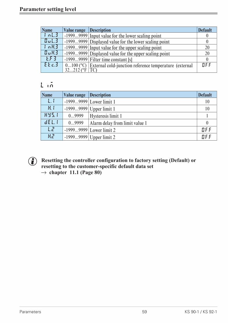
g Resetting the controller configuration to factory setting (Default) or
resetting to the customer-specific default data set
r chapter 11.1 (Page 80)
Parameter setting level
Parameters 59 KS 90-1 / KS 92-1
Name Value range Description DefaultInL.3 -1999...9999 Input value for the lower scaling point 0OuL.3 -1999...9999 Displayed value for the lower scaling point 0InH.3 -1999...9999 Input value for the upper scaling point 20OuH.3 -1999...9999 Displayed value for the upper scaling point 20t.F3 -1999...9999 Filter time constant [s] 0Etc.3 0...100 (°C)
32...212 (°FExternal cold-junction reference temperature (externalTC)
OFF
Lim
Name Value range Description Default
L.1 -1999...9999 Lower limit 1 10H.1 -1999...9999 Upper limit 1 10
HYS.1 0...9999 Hysteresis limit 1 1dEl.1 0...9999 Alarm delay from limit value 1 0L.2 -1999...9999 Lower limit 2 OFF
H.2 -1999...9999 Upper limit 2 OFF
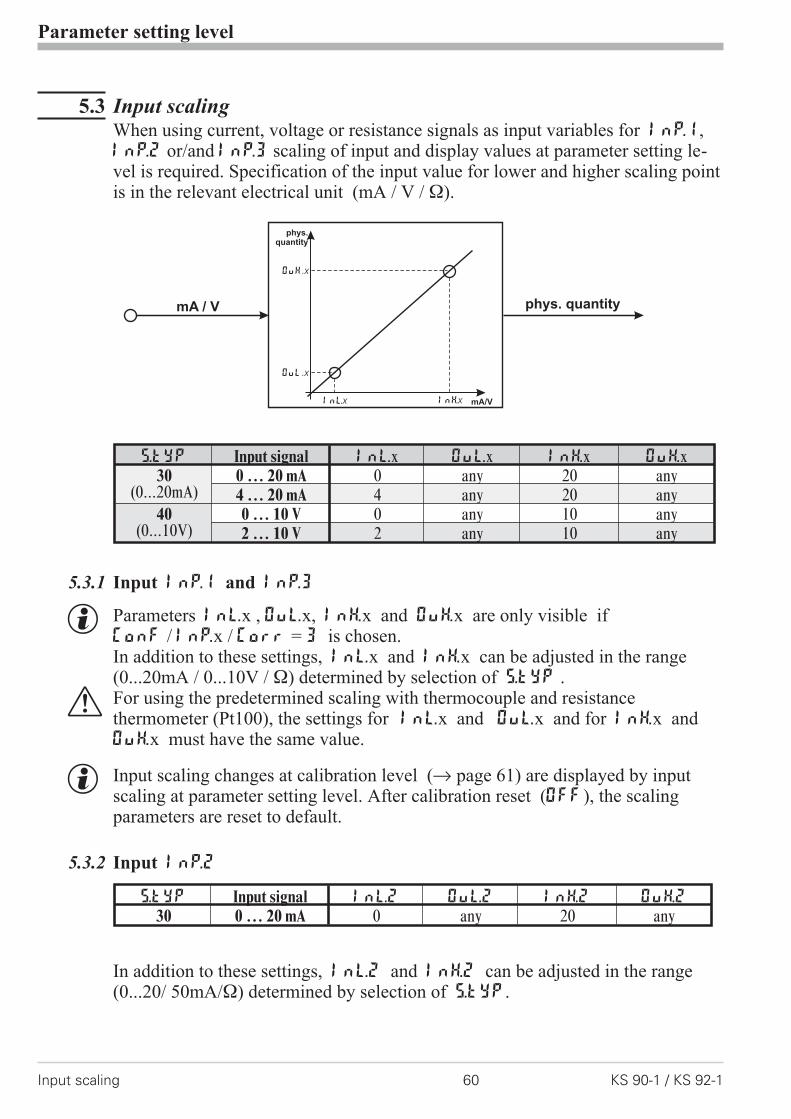
5.3 Input scalingWhen using current, voltage or resistance signals as input variables for InP.1,InP.2 or/and InP.3 scaling of input and display values at parameter setting le-vel is required. Specification of the input value for lower and higher scaling pointis in the relevant electrical unit (mA / V / �).
5.3.1 Input Inp.1 and InP.3
g Parameters InL.x , OuL.x, InH.x and OuH.x are only visible ifConF / InP.x / Corr = 3 is chosen.In addition to these settings, InL.x and InH.x can be adjusted in the range(0...20mA / 0...10V / �) determined by selection of S.tYP .
a For using the predetermined scaling with thermocouple and resistancethermometer (Pt100), the settings for InL.x and OuL.x and for InH.x andOuH.x must have the same value.
g Input scaling changes at calibration level (r page 61) are displayed by inputscaling at parameter setting level. After calibration reset (OFF), the scalingparameters are reset to default.
5.3.2 Input InP.2
In addition to these settings, InL.2 and InH.2 can be adjusted in the range(0...20/ 50mA/�) determined by selection of S.tYP.
Parameter setting level
Input scaling 60 KS 90-1 / KS 92-1
mA/V
phys.quantity
mA / V phys. quantity
OuH.x
OuL.x
InH.xInL.x
S.tYP Input signal InL.x OuL.x InH.x OuH.x30
(0...20mA)0 … 20 mA 0 any 20 any4 … 20 mA 4 any 20 any
40(0...10V)
0 … 10 V 0 any 10 any2 … 10 V 2 any 10 any
S.tYP Input signal InL.2 OuL.2 InH.2 OuH.2
30 0 … 20 mA 0 any 20 any
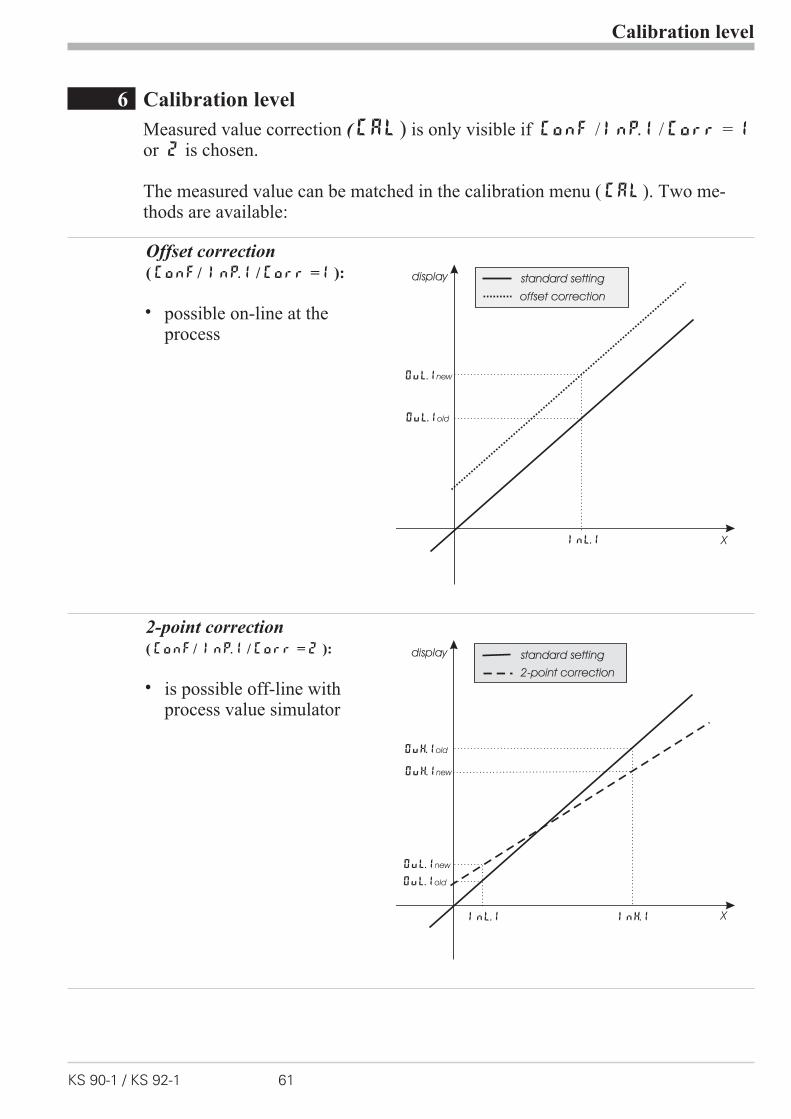
6 Calibration level
Measured value correction ( CAL) is only visible if ConF / InP.1 / Corr = 1or 2 is chosen.
The measured value can be matched in the calibration menu ( CAL). Two me-thods are available:
Offset correction
( ConF/ InP.1 / Corr =1 ):
w possible on-line at theprocess
2-point correction( ConF/ InP.1 / Corr = 2 ):
w is possible off-line withprocess value simulator
Calibration level
KS 90-1 / KS 92-1 61
X
standard setting
offset correction
InL.1
OuL.1new
display
OuL.1old
X
standard setting
2-point correction
InL.1 InH.1
OuL.1new
OuH.1new
display
OuH.1old
OuL.1old

Offset correction ( ConF/ InP.1 / Corr =1 ):
InL.1: The input value of the scaling point is displayed.The operator must wait, until the process is at rest.Subsequently, the operator acknowledges the input value by pressingkey Ù.
OuL.1: The display value of the scaling point is displayed.Before calibration, OuL.1 is equal to InL.1.The operator can correct the display value by pressing keys ÈÌ .Subsequently, he confirms the display value by pressing key Ù.
Calibration level
62 KS 90-1 / KS 92-1
r
Ì
Ù3 sec.
r PArA
CALrÙr InP.1 Ùr InL.1r r Ù
r
:
OuL.1r r Ù
Endr r Ù
ÌÈ
12001199°C°F
SP.2SP.E
parafuncAda
Err
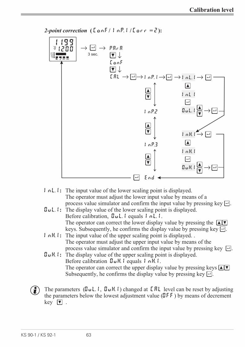
2-point correction ( ConF/ InP.1 / Corr = 2):
InL.1: The input value of the lower scaling point is displayed.The operator must adjust the lower input value by means of aprocess value simulator and confirm the input value by pressing key Ù.
OuL.1: The display value of the lower scaling point is displayed.Before calibration, OuL.1 equals InL.1.The operator can correct the lower display value by pressing the ÈÌkeys. Subsequently, he confirms the display value by pressing key Ù.
InH.1: The input value of the upper scaling point is displayed. .The operator must adjust the upper input value by means of theprocess value simulator and confirm the input value by pressing key Ù.
OuH.1: The display value of the upper scaling point is displayed.Before calibration OuH.1 equals InH.1.The operator can correct the upper display value by pressing keys ÈÌSubsequently, he confirms the display value by pressing key Ù.
g The parameters (OuL.1, OuH.1) changed at CAL level can be reset by adjustingthe parameters below the lowest adjustment value (OFF) by means of decrementkey Ì .
Calibration level
KS 90-1 / KS 92-1 63
12001199°C°F
SP.2SP.E
parafuncAda
Err
r
Ì
Ù3 sec.
r PArA
CALrÙr InP.1 Ùr r r Ù
Ù
InL.1
È
InL1
Ù
OuL.1 rÙÌÈ
r ÙInH.1
È
InH.1
Ù
OuH.1 rÙÌÈ
ConFr
Ì
r
ÌÈ
InP.2
InP.3
ÌÈ
End
ÌÈ

7 Special functions
7.1 DAC®– motor actuator monitoring
(Digital Actor Control DAC®)
With all controllers with position feedback Yp, the motor actuator can be monito-red for functional troubles. The DAC® function can be started by chosing the pa-rameter C.Fnc = 5 or 6 at the configuration level ( ConF):
w ConF / Cntr / C.Fnc = 5 3-point-stepping controller withposition feedback Yp as potentiometer
w ConF / Cntr / C.Fnc = 6 Continuous controller with integratedpositioner and position feedback Yp aspotentiometer
If an error occures, the controller switches to manual operation (ò - LED blinks)and no impulses are given out any longer. If one of the relays shall switch when a
DAC® error occures, parameter dAC.A = 1 and inverse action O.Act = 1 mustbe selected for the relevant output OUT.1 … OUT.4 in the ConF menu
( OUt.3 and 4 only possible if O.tYP = 0 [relay/logic]):
w ConF / OUt.x / dAc.A = 1 Motor actuator monitoring (DAC) aktive
The system detects the following stepping controller errors:
w defective motor
w defective capacitor (wrong rotating direction)
w wrong phase followers (wrong rotating direction)
w defective force transmission at spindle or drive
w excessive backlash due to wear
w jamming of the control valve e.g. due to foreign body
In these cases the controller will change to manual operation and the outputs willbe switched off. Is the controller switched to automatic operation again or anymodification is done the controller activates the DAC function again and the out-puts will be setted.
Resetting of a DAC error:After solving the technical problem the DAC errror can be acknowledged in theerror list. Thereafter the controller works again in normal operation mode.
See also chapter 3.4 "Mainenance manager / Error list", page 12 ff.
Special functions
DAC®
– motor actuator monitoring 64 KS 90-1 / KS 92-1
Functioning of the DAC functionNo input filter should be defined for the Yp input ( PArA / InP.x / t.Fx = 0 ).Therewith no wrong detection of blocking or wrong method of operation can berecognized.The automatic calibration can be used with drives outfitted with spring assembly.
Execution of the calibration:It is controlled if the mean alteration between two messurements is enough forthe DAC monitoring. The calibration will be stopped if the alteration betweentwo messurements is too small.The position of 0% is searched. Therefor the drive will be closed until there is nochanging of the input signal for 0,5 sec.Assuming that the drive is outfitted with spring assembly, the drive is opened for2,8 sec. The drive should then still be within the spring assembly. This position isallocated and stored as 0%.With the same procedure the position for 100% is allocated and stored.Simultaneously the motor running time is determined and saved as parameter tt.Afterwards the controller sets the drive in the position before calibration.Was the controller in automatic mode before calibration it will be set to automa-tic mode again otherwise it remains in manual mode.
The following errors can be occure during calibration:
w the change of the Yp input is to small, no monitoring is possible
w the motion is in wrong direction
w the Yp input is broken
In these cases the automatic calibration will be stopped and the controller remainsin manual mode.
g If the automatic calibration leads to no resonable results the calibration of the Ypinput can be done manual.
g If the conroller reaches the positions of 0% or 100% the outputs will be switchedoff. Also in manual mode it is not possible to exceed these limits.
g Because no controller with continuouse output and Yp input is defined there
won't be the DAC function for this controlling type.
Special functions
KS 90-1 / KS 92-1 65 DAC®
– motor actuator monitoring
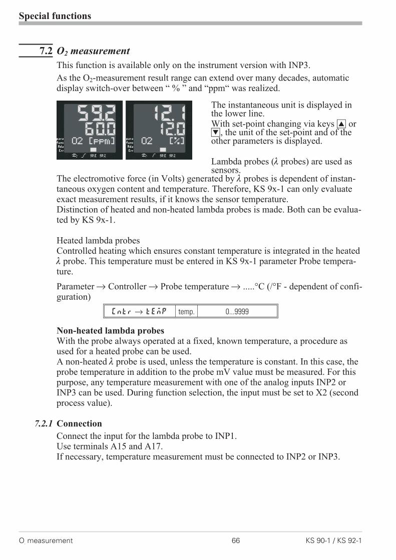
7.2 O2 measurement
This function is available only on the instrument version with INP3.
As the O2-measurement result range can extend over many decades, automaticdisplay switch-over between “ % ” and “ppm“ was realized.
The instantaneous unit is displayed inthe lower line.With set-point changing via keys I orD, the unit of the set-point and of theother parameters is displayed.
Lambda probes ( probes) are used assensors.
The electromotive force (in Volts) generated by probes is dependent of instan-taneous oxygen content and temperature. Therefore, KS 9x-1 can only evaluateexact measurement results, if it knows the sensor temperature.Distinction of heated and non-heated lambda probes is made. Both can be evalua-ted by KS 9x-1.
Heated lambda probesControlled heating which ensures constant temperature is integrated in the heated probe. This temperature must be entered in KS 9x-1 parameter Probe tempera-ture.
Parameter r Controller r Probe temperature r .....°C (/°F - dependent of confi-guration)
Cntrr tEmP temp. 0...9999
Non-heated lambda probesWith the probe always operated at a fixed, known temperature, a procedure asused for a heated probe can be used.A non-heated probe is used, unless the temperature is constant. In this case, theprobe temperature in addition to the probe mV value must be measured. For thispurpose, any temperature measurement with one of the analog inputs INP2 orINP3 can be used. During function selection, the input must be set to X2 (secondprocess value).
7.2.1 Connection
Connect the input for the lambda probe to INP1.Use terminals A15 and A17.If necessary, temperature measurement must be connected to INP2 or INP3.
Special functions
O2measurement 66 KS 90-1 / KS 92-1
7.2.2 Configuration:
Oxygen measurement
Oxygen measurement with heated lambda probeController r Process value processing r 7: O2 functions with constant probetemperature
Cntrr C.tYP 7 O2-const
Oxygen measurement with non-heated lambda probeController r Process value processing r O2 functions with measured probetemperature
Cntrr C.tYP 8 O2+temp
Input 1 r Function INP1 r 7: process value X1
InP.1 r 1.Fnc 7 X1-Input
In input 1, the sensor type is set for one of the high-impedance voltage inputs:Input 1 r Sensor type r 42: special (-25...1150 mV) or
41: special (-2,5...115 mV)
InP.1 r S.tyP 41 115 mV
InP.1 r S.tyP 42 1150 mV
Input 1 r meas. value correction r 0: no correction
InP.1 r S.Lin 0 no
Temperature measurement (required with non-heated lambda probe)Any temperature measurement with one of analog inputs INP2 or INP3 can beused. Select input X2 during function selection (second set-point).
g With O2 measurement, evaluation in ppm or % must be specified for allparameters related to the process value.This is done centrally during configuration.
Other r Parameter unit for O2r 0: parameter for O2 function in ppm1: parameter for O2 function in %
othrr O2 0 unit : ppm
othrr O2 1 unit : %
g Whether the temperature of the non-heated probe is specified in °C or °F canbe selected during configuration.Other r Unit r 1: in Celsius
2: in Fahrenheit
othrr Unit 1 °C
othrr Unit 2 °F
Special functions
KS 90-1 / KS 92-1 67 O2measurement
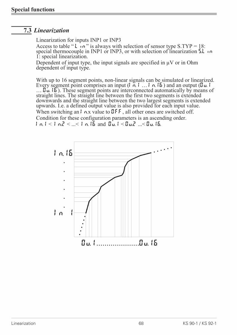
7.3 Linearization
Linearization for inputs INP1 or INP3Access to table “ Lin” is always with selection of sensor type S.TYP = 18:special thermocouple in INP1 or INP3, or with selection of linearization S.Lin1: special linearization.Dependent of input type, the input signals are specified in µV or in Ohmdependent of input type.
With up to 16 segment points, non-linear signals can be simulated or linearized.Every segment point comprises an input (In.1 … In.16) and an output (Ou.1… Ou.16). These segment points are interconnected automatically by means ofstraight lines. The straight line between the first two segments is extendeddownwards and the straight line between the two largest segments is extendedupwards. I.e. a defined output value is also provided for each input value.When switching an In.x value to OFF, all other ones are switched off.Condition for these configuration parameters is an ascending order.In.1 < In.2 < ...< In.16 and Ou.1 < Ou.2 ...< Ou.16.
Special functions
Linearization 68 KS 90-1 / KS 92-1
In.16
In 1
.
.
.
.
.
.
Ou.1 Ou.16.....................
7.4 Loop alarmThe loop alarm monitors the control loop for interruption(not with three-point stepping controller and not with signallers.)With parameter LP.AL switched to 1(= loop alarm active), an interruption ofthe control loop is detected, unless the process value reacts accordingly withY=100% after elapse of 2xTi.The loop alarm shows that the control loop is interrupted. You should check hea-ting or cooling circuit, sensor, controller and motor actuator.During self-tuning, the control loop is not monitored (loop alarm is not active).
7.5 Heating current input / heating current alarmThe heating current alarm monitors the heating current.In addition to short circuit monitoring, checking either for overload (current >heating current limit value) or for interruption (current < heating current limit va-lue) is done.Each of the analog inputs can be used as measurement input.If electrical heating is concerned, INP2 which is always provided can be configu-red for measuring range 0...50mA AC and connected directly using a heating cur-rent transformer.
a With t1 < 400 ms or tp < 200 ms (effective time!), heating current monitoringis ineffective.
Special functions
KS 90-1 / KS 92-1 69 Loop alarm

7.6 KS9x-1 as Modbus master
a This function is only selectable with BlueControl (engineering tool)!
The KS9x-1 can be used as Modbus master ( ConF / othr / MASt = 1 ). TheModbus master sends ist data to all slaves (Broadcast message, controller adress0). It transmits its data (modbus adress AdrU) cyclic with the cycle time Cycl tothe bus. The slave controller receives the data transmitted by the masters and al-locates it to the modbus target adress AdrO. If more than one data should betransmitted by the master controller ( Numb > 1) , the modbus adress AdrU in-dicates the start adress of the data that should be transmitted and AdrO indicatesthe first target adress where the received data should be stored. The followingdata will be stored at the logically following modbus target adresses.With this it is possible e.g. to specify the process value of the master controller asset-point for the slave controllers.
7.7 Back-up controller (PROFIBUS)Back-up operation: calculation of the control outputs is in the master. The con-troller is used for process value measurement, correcting variable output and fordisplay.With master or communication failure, control is taken over independently andbumplessly by the controller.
Special functions
KS9x-1 as Modbus master 70 KS 90-1 / KS 92-1
Additions othr (only visible with BlueControl!)
Name Value range Description Default
MASt Controller is used as Modbus master 0
0 Slave1 Master
Cycl 0...200 Cycle time [ms] for the Modbus master to transmit itsdata to the bus.
60
AdrO 1...65535 Target address to which the with AdrU specified datais given out on the bus.
1
AdrU 1...65535 Modbus address of the data that Modbus master givesto the bus.
1

8 BlueControl
BlueControl is the projecting environment for the BluePort� controller series ofPMA. The following 3 versions with graded functionality are available:
The mini version is - free of charge - at your disposal as download at PMA home-page www.pma-online.de or on the PMA-CD (please ask for).
At the end of theinstallation the li-cence number hasto be stated orDEMO modemust be chosen.
At DEMO modethe licence num-ber can be statedsubsequently un-der Help r Li-cence r Change.
BlueControl
KS 90-1 / KS 92-1 71
Functionality Mini Basic Expert
Parameter and configuration setting yes yes yes
Controller and loop simulation yes yes yes
Download: transfer of an engineering to the controller yes yes yes
Online mode / visualization SIM only yes yes
Defining an application specific linearization yes yes yes
Configuration in the extended operating level yes yes yes
Upload: reading an engineering from the controller SIM only yes yes
Basic diagnostic functions no no yes
Saving data file and engineering no yes yes
Printer function no yes yes
Online documentation, help yes yes yes
Implementation of measurement value correction yes yes yes
Data acquisition and trend display SIM only yes yes
Wizard function yes yes yes
Extended simulation no no yes
Customer-specific default data-set no no yes
Programeditor (KS 90-1programmer only) no no yes
Support for the "railline"-system no no yes
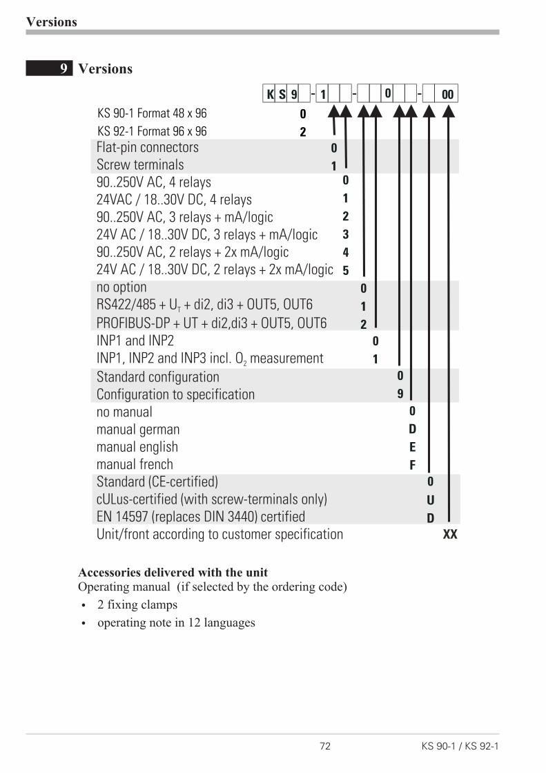
9 Versions
Accessories delivered with the unitOperating manual (if selected by the ordering code)
w 2 fixing clamps
w operating note in 12 languages
Versions
72 KS 90-1 / KS 92-1
XX
2
Flat-pin connectors
Screw terminals
90..250V AC, 4 relays
24VAC / 18..30V DC, 4 relays
90..250V AC, 3 relays + mA/logic
24V AC / 18..30V DC, 3 relays + mA/logic
90..250V AC, 2 relays + 2x mA/logic
24V AC / 18..30V DC, 2 relays + 2x mA/logic
no option
RS422/485 + U + di2, di3 + OUT5, OUT6
PROFIBUS-DP + UT + di2,di3 + OUT5, OUT6
INP1 and INP2
INP1, INP2 and INP3 incl. O measurement
Standard configuration
Configuration to specification
no manual
manual german
manual english
manual french
Standard (CE-certified)
cULus-certified (with screw-terminals only)
EN 14597 (replaces DIN 3440) certified
Unit/front according to customer specification
T
2
KS 92-1 Format 96 x 96
KS 90-1 Format 48 x 96 0

Accessory equipment with ordering information
Versions
KS 90-1 / KS 92-1 73
Description Order no.Heating current transformer 50A AC 9404-407-50001PC-adaptor for the front-panel interface 9407-998-00001Standard rail adaptor 9407-998-00061Operating manual German 9499-040-62918Operating manual English 9499-040-62911Operating manual French 9499-040-62932Operating manual Russian 9499-040-62965Interface description Modbus RTU German 9499-040-63718Interface description Modbus RTU English 9499-040-63711BlueControl (engineering tool) Mini Download www.pma-online.deBlueControl (engineering tool) Basic 9407-999-11001BlueControl (engineering tool) Expert 9407-999-11011

10 Technical data
INPUTS
PROCESS VALUE INPUT INP1
Resolution: > 14 bits
Decimal point: 0 to 3 digits behind the decimalpoint
Dig. input filter: adjustable 0,000...9999 s
Scanning cycle: 100 ms
Measured valuecorrection:
2-point or offset correction
Thermocouplesr Table 1 (page 77 )
Internal and external temperature compensation
Input resistance: 1 M�
Effect of source resistance: 1 �V/�
Internal temperature compensation
Maximal additional error: � 0.5 K
Sensor break monitoring
Sensor current: � 1 �A
Configurable output action
Thermocouple to specificationMeasuring range -25...75mV in conjunction with
the linearization can be used for connecting
thermocouples which are not included in Table 1.
Resistance thermometerr Table 2 (page 77 )
Connection: 3-wire
Lead resistance: max. 30 Ohm
Input circuit monitor: break and short circuit
Special measuring range
BlueControl (engineering tool) can be used to
match the input to sensor KTY 11-6 (character-
istic is stored in the controller).
Physical measuring range: 0...4500 Ohm
Linearization segments 16
Current and voltage signalsr Table 3 (page 77 )
Span start, end of span: anywhere within measuring range
Scaling: selectable -1999...9999
Linearization: 16 segments, adaptable withBlueControl
Decimal point: adjustable
Input circuit monitor: 12.5% below span start (2mA, 1V)
SUPPLEMENTARY INPUT INP2
Resolution: > 14 bits
Scanning cycle: 100 ms
Heating current measurementvia current transformer (� Accessory equipment)
Measuring range: 0...50mA AC
Scaling: adjustable -1999...0.000...9999 A
Current measuring rangeTechnical data as for INP1
Potentiometerr Table 2 (page 77 )
Connection: 2-wire
Lead resistance: max. 30 Ohm
Input circuit monitor: Break
SUPPLEMENTARY INPUT INP3 (OPTION)
Resolution: > 14 bits
Scanning cycle: 100 ms
Technical data as for INP1 except 10V range.
CONTROL INPUTS DI1, DI2
Configurable as switch or push-button!
Connection of a potential-free contact suitable
for switching “dry” circuits.
Switched voltage: 5 V
Current: 100 �A
CONTROL INPUTS DI2, DI3 (OPTION)
The functions of control input di2 on the analog
card and of di2 on the options card are logically
ORed.
Configurable as direct or inverse switches or keys.
Optocoupler input for active triggering.
Technical data
74 KS 90-1 / KS 92-1
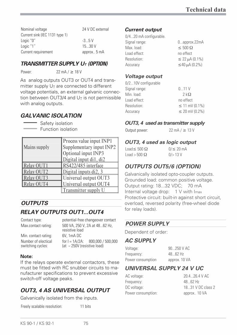
Nominal voltage 24 V DC external
Current sink (IEC 1131 type 1)
Logic “0” -3...5 V
Logic “1” 15...30 V
Current requirement approx.. 5 mA
TRANSMITTER SUPPLY UT (OPTION)
Power: 22 mA / � 18 V
As analog outputs OUT3 or OUT4 and trans-
mitter supply UT are connected to different
voltage potentials, an external galvanic connec-
tion between OUT3/4 and UT is not permissible
with analog outputs.
GALVANIC ISOLATION
Safety isolation
Function isolation
OUTPUTS
RELAY OUTPUTS OUT1...OUT4
Contact type: potential-free changeover contact
Max.contact rating: 500 VA, 250 V, 2A at 48...62 Hz,resistive load
Min. contact rating: 6V, 1mA DC
Number of electicalswitching cycles:
for I = 1A/2A: 800,000 / 500,000(at ~ 250V (resistive load)
Note:
If the relays operate external contactors, thesemust be fitted with RC snubber circuits to ma-nufacturer specifications to prevent excessiveswitch-off voltage peaks.
OUT3, 4 AS UNIVERSAL OUTPUT
Galvanically isolated from the inputs.
Freely scalable resolution: 11 bits
Current output
0/4...20 mA configurable.
Signal range: 0...approx.22mA
Max. load: � 500 �
Load effect: no effect
Resolution: � 22 �A (0.1%)
Accuracy �40 �A (0.2%)
Voltage output
0/2...10V configurable
Signal range: 0...11 V
Min. load: 2 k�
Load effect: no effect
Resolution: � 11 mV (0.1%)
Accuracy � 20 mV (0.2%)
OUT3, 4 used as transmitter supply
Output power: 22 mA / � 13 V
OUT3, 4 used as logic output
Load� 500 � 0/� 20 mA
Load > 500 � 0/> 13 V
OUTPUTS OUT5/6 (OPTION)
Galvanically isolated opto-coupler outputs.
Grounded load: common positive voltage.
Output rating: 18...32 VDC; 70 mA
Internal voltage drop: 1 V with Imax
Protective circuit: built-in against short circuit,
overload, reversed polarity (free-wheel diode
for relay loads).
POWER SUPPLY
Dependent of order:
AC SUPPLY
Voltage: 90...250 V AC
Frequency: 48...62 Hz
Power consumption approx. 10 VA
UNIVERSAL SUPPLY 24 V UC
AC voltage: 20.4...26.4 V AC
Frequency: 48...62 Hz
DC voltage: 18...31 V DC class 2
Power consumption: approx.. 10 VA
Technical data
KS 90-1 / KS 92-1 75
Process value input INP1Mains supply Supplementary input INP2
Optional input INP3Digital input di1, di2
Relay OUT1 RS422/485 interfaceRelay OUT2 Digital inputs di2, 3Relay OUT3 Universal output OUT3Relay OUT4 Universal output OUT4
Transmitter supply UT
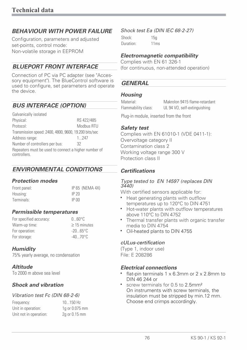
BEHAVIOUR WITH POWER FAILURE
Configuration, parameters and adjusted
set-points, control mode:
Non-volatile storage in EEPROM
BLUEPORT FRONT INTERFACE
Connection of PC via PC adapter (see "Acces-sory equipment"). The BlueControl software isused to configure, set parameters and operatethe device.
BUS INTERFACE (OPTION)
Galvanically isolated
Physical: RS 422/485
Protocol: Modbus RTU
Transmission speed: 2400, 4800, 9600, 19.200 bits/sec
Address range: 1...247
Number of controllers per bus: 32
Repeaters must be used to connect a higher number ofcontrollers.
ENVIRONMENTAL CONDITIONS
Protection modes
Front panel: IP 65 (NEMA 4X)
Housing: IP 20
Terminals: IP 00
Permissible temperatures
For specified accuracy: 0...60°C
Warm-up time: ≥ 15 minutes
For operation: -20...65°C
For storage: -40...70°C
Humidity75% yearly average, no condensation
AltitudeTo 2000 m above sea level
Shock and vibration
Vibration test Fc (DIN 68-2-6)
Frequency: 10...150 Hz
Unit in operation: 1g or 0.075 mm
Unit not in operation: 2g or 0.15 mm
Shock test Ea (DIN IEC 68-2-27)
Shock: 15g
Duration: 11ms
Electromagnetic compatibilityComplies with EN 61 326-1
(for continuous, non-attended operation)
GENERAL
Housing
Material: Makrolon 9415 flame-retardant
Flammability class: UL 94 VO, self-extinguishing
Plug-in module, inserted from the front
Safety testComplies with EN 61010-1 (VDE 0411-1):
Overvoltage category II
Contamination class 2
Working voltage range 300 V
Protection class II
Certifications
Type tested to EN 14597 (replaces DIN3440)
With certified sensors applicable for:
w Heat generating plants with outflowtemperatures up to 120°C to DIN 4751
w Hot-water plants with outflow temperaturesabove 110°C to DIN 4752
w Thermal transfer plants with organic transfermedia to DIN 4754
w Oil-heated plants to DIN 4755
cULus-certification
(Type 1, indoor use)
File: E 208286
Electrical connectionsw flat-pin terminals 1 x 6.3mm or 2 x 2.8mm to
DIN 46 244 orw screw terminals for 0.5 to 2.5mm²
On instruments with screw terminals, theinsulation must be stripped by min.12 mm.Choose end crimps accordingly.
Technical data
76 KS 90-1 / KS 92-1

MountingPanel mounting with two fixing clamps at top/ bot-
tom or right/left, high-density mounting possible
Mounting position: uncritical
Weight: 0.27kg
Accessories delivered with the unitOperating manual
Fixing clamps
Technical data
KS 90-1 / KS 92-1 77
Thermoelementtype Measuring range Accuracy Resolution (Ô)L Fe-CuNi (DIN) -100...900°C -148...1652°F ß 2K 0.1 KJ Fe-CuNi -100...1200°C -148...2192°F ß 2K 0.1 KK NiCr-Ni -100...1350°C -148...2462°F ß 2K 0.2 KN Nicrosil/Nisil -100...1300°C -148...2372°F ß 2K 0.2 KS PtRh-Pt 10% 0...1760°C 32...3200°F ß 2K 0.2 KR PtRh-Pt 13% 0...1760°C 32...3200°F ß 2K 0.2 KT Cu-CuNi -200...400°C -328...752°F ß 2K 0.05 KC W5%Re-W26%Re 0...2315°C 32...4199°F ß 2K 0.4 KD W3%Re-W25%Re 0...2315°C 32...4199°F ß 2K 0.4 KE NiCr-CuNi -100...1000°C -148...1832°F ß 2K 0.1 KB * PtRh-Pt6% 0(100)...1820°C 32(212)...3308°F ß 2K 0.3 K
* Specifications valid for 400°C
Table 1 Thermocouples measuring ranges
Type Signal Current Measuring range Accuracy Resolution (Ô)Pt100
0,2mA
-200...100°C (150**) -140...212°F ß 1K 0.1KPt100 -200...850°C -140...1,562°F ß 1K 0.1KPt1000 -200...850°C -140...1562°F ß 2K 0.1KKTY 11-6 * -50...150°C -58...302°F ß 2K 0.05KSpezial 0...4,500
ß 0.1 % 0.01 %
Spezial 0...450Poti 0...160Poti 0...450Poti 0...1,600Poti 0...4,500
* Or special
**Measuring range 150°C with reduced lead resistance. Max. 160 [ for meas. and lead
resistances (150°C = 157,33 [).
Table 2 Resistance transducer measuring ranges
Measuring range Input impedance Accuracy Resolution (Ô)0-10 Volt ~ 110 k� ß 0.1 % 0.6 mV-2,5-115 mV ? 1M� ß 0.1 % 6 �V-25-1,150 mV ? 1M� ß 0.1 % 60 �V
Table 3 Current and voltage measuring ranges
11 Safety hints
This unit was
– built and tested in compliance with VDE 0411-1 / EN 61010-1 and
– delivered in safe condition.
– complies European guideline 89/336/EWG (EMC) and is provided with CE marking.
– tested before delivery and passed the tests required by test schedule.
– To maintain this condition and to ensure safe operation, the user must follow
the hints and warnings given in this operating manual.
– The unit is intended exclusively for use as a measurement and control instru-
ment in technical installations.
a WarningIf the unit is damaged to an extent that safe operation seems impossible, the unitmust not be taken into operation.
ELECTRICAL CONNECTIONS
– The electrical wiring must conform to local standards (e.g. VDE 0100).
– The input measurement and control leads must be kept separate from signal
and power supply leads.
– In the installation of the controller a switch or a circuit-breaker must be used
and signified.
– The switch or circuit-breaker must be installed near by the controller and the
user must have easy access to the controller.
COMMISSIONINGBefore instrument switch-on, check that the following information is taken intoaccount:
w Ensure that the supply voltage corresponds to the specifications on the type label.
w All covers required for contact protection must be fitted.
w If the controller is connected with other units in the same signal loop, checkthat the equipment in the output circuit is not affected before switch-on. Ifnecessary, suitable protective measures must be taken.
w The unit may be operated only in installed condition.
w Before and during operation, the temperature restrictions specified forcontroller operation must be met.
Safety hints
78 KS 90-1 / KS 92-1
SHUT-DOWNFor taking the unit out of operation, disconnect it from all voltage sources andprotect it against accidental operation.If the controller is connected with other equipment in the same signal loop, checkthat other equipment in the output circuit is not affected before switch-off. If ne-cessary, suitable protective measures must be taken.
MAINTENANCE, REPAIR AND MODIFICATIONThe units do not need particular maintenance.
a WarningWhen opening the units, or when removing covers or components, live parts andterminals may be exposed.
Before starting this work, the unit must be disconnected completely.
After completing this work, re-shut the unit and re-fit all covers and components. Checkif specifications on the type label must be changed and correct them, if necessary.
l CautionWhen opening the units, components which are sensitive to electrostatic dischar-ge (ESD) can be exposed. The following work may be done only at workstationswith suitable ESD protection.
Modification, maintenance and repair work may be done only by trained and aut-horized personnel. For this purpose, the PMA service should be contacted.
a The cleaning of the front of the controller should be done with a dry or a wetted(spirit, water) handkerchief.
Safety hints
KS 90-1 / KS 92-1 79
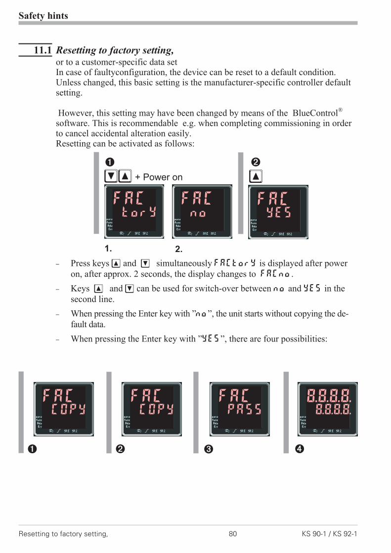
11.1 Resetting to factory setting,or to a customer-specific data setIn case of faultyconfiguration, the device can be reset to a default condition.Unless changed, this basic setting is the manufacturer-specific controller defaultsetting.
However, this setting may have been changed by means of the BlueControl®
software. This is recommendable e.g. when completing commissioning in orderto cancel accidental alteration easily.Resetting can be activated as follows:
– Press keys È and Ì simultaneously FACtory is displayed after power
on, after approx. 2 seconds, the display changes to FACno.
– Keys È and Ì can be used for switch-over between no and yEs in the
second line.
– When pressing the Enter key with ”no”, the unit starts without copying the de-
fault data.
– When pressing the Enter key with ”yEs”, there are four possibilities:
Safety hints
Resetting to factory setting, 80 KS 90-1 / KS 92-1
ÌÈ + Power on
1 2
È
1. 2.
FACTory
FACno
FACYEs
1 2 3 4
FACCOPY
FACCOPY
FACPASS
8.8.8.8.8.8.8.8.

Safetyswitches
Levels Password Instrument reaction after confirming”YES” by pressingÙ
1 closed any any always factory reset2 open free none Factory reset without prompt for the password3 open free defined Factory reset after entry of the correct pass
number4 open min. 1
disabledany Factory reset is omitted
g TimeoutUnless a key is pressed during 10 seconds, a timeout occurs and the instrumentsstarts without copying the default data.
g The process COPY can take several seconds.Subsequently, the instrument changes to normal operation.
Safety hints
KS 90-1 / KS 92-1 81 Resetting to factory setting,

Index
0-9
2-point correction. . . . . . . . . . . . 61
A
Alarm handling . . . . . . . . . . 26 - 27
B
Bargraph . . . . . . . . . . . . . . . . 11
BlueControl. . . . . . . . . . . . . . . 71
Bus interface
- Technical Data . . . . . . . . . . 76
C
Calibration level (CAL) . . . . . . 61 - 63
Certifications . . . . . . . . . . . . . . 76
Configuration examples
- 2-point controller . . . . . . . . . 49- 3-point controller . . . . . . . . . 50- 3-point stepping controller . . . . 51- Continuous controller . . . . . . . 52- D - Y -Off controller . . . . . . . 53- Measured value output . . . . . . 55- Signaller . . . . . . . . . . . . . . 48
Configuration level
- Configuration parameters . . 30 - 43- Parameter survey . . . . . . . . . 29
Connecting diagram . . . . . . . . . . . 6
Connecting examples
- di2/3, 2-wire transmitter supply . . 8- INP2 current transformer . . . . . . 7- OUT1/2 heating/cooling . . . . . . 7- OUT3 as logic output . . . . . . . 10- OUT3 transmitter supply . . . . . . 9- RS485 interface. . . . . . . . . . . 9
Control inputs di1, di2, di3
- Technical data . . . . . . . . . . . 74
Cooling functions
- Constant period . . . . . . . . . . 47- Standard . . . . . . . . . . . . . . 45- Water cooling non-linear . . . . . 46
Current signal measuring range . . . . 74
D
DAC . . . . . . . . . . . . . . . . 64 - 65
Digital inputs di1, di2, di3
- Configuration . . . . . . . . . . . 38- Technical data . . . . . . . . . . . 74
E
Environmental conditions . . . . . . . 76
Equipment . . . . . . . . . . . . . . . 73
Error list . . . . . . . . . . . . . . . . 13
F
Front view . . . . . . . . . . . . . . . 11
I
Input INP1
- Configuration . . . . . . . . . . . 31- Parameters. . . . . . . . . . . . . 58- Technical data . . . . . . . . . . . 74
Input INP2
- Configuration . . . . . . . . . . . 33- Parameters. . . . . . . . . . . . . 58- Technical data . . . . . . . . . . . 74
Input INP3
- Configuration . . . . . . . . . . . 33- Parameters. . . . . . . . . . . . . 59- Technical data . . . . . . . . . . . 74
Input scaling . . . . . . . . . . . . . . 60
L
LED
- Ada - LED. . . . . . . . . . . . . 11- Err - LED . . . . . . . . . . . . . 11- func - LED . . . . . . . . . . . . 11- ì - LED . . . . . . . . . . . . . 11- LED colours. . . . . . . . . . . . 11- ò - LED . . . . . . . . . . . . . 11- para - LED . . . . . . . . . . . . 11- SP.2 - LED . . . . . . . . . . . . 11- SP.x - LED . . . . . . . . . . . . 11
82 KS 90-1 / KS 92-1

Linearization . . . . . . . . . . . . . . 68
M
Mainenance manager . . . . . . . 13 - 15
Manual tuning . . . . . . . . . . . . . 24
Modbus master . . . . . . . . . . . . . 70
Mounting. . . . . . . . . . . . . . . . . 5
O
O2-measurement . . . . . . . . . . . . 66
Offset correction . . . . . . . . . . . . 61
Optimization at the setpoint . . . . . . 18
Output OUT1
- Configuration . . . . . . . . . . . 36- Technical data . . . . . . . . . . . 75
Output OUT2
- Technical data . . . . . . . . . . . 75
Output OUT3
- Configuration . . . . . . . . . . . 37- Technical data . . . . . . . . . . . 75
Output OUT4
- Technical data . . . . . . . . . . . 75
Output OUT5
- Configuration . . . . . . . . . . . 38- Technical data . . . . . . . . . . . 75
Output OUT6
- Configuration . . . . . . . . . . . 38- Technical data . . . . . . . . . . . 75
Oxygen measurement . . . . . . . . . 66
P
Parameter setting level
- Parameter survey . . . . . . . . . 56- Parameters . . . . . . . . . . 57 - 59
Power supply . . . . . . . . . . . . . . 75
R
Ramp . . . . . . . . . . . . . . . . . . 44
Resetting to factory setting . . . . 80 - 81
Resistance thermometer measuring range. . . . . . . . . . . . . . . . . . . . . 74
S
Safety hints . . . . . . . . . . . . 78 - 81
Safety switch. . . . . . . . . . . . . . . 5
Safety test. . . . . . . . . . . . . . . . 76
Self-tuning
- Cancelation . . . . . . . . . . . . 21- Cancelation causes . . . . . . . . 22
SEtP. . . . . . . . . . . . . . . . . . . 58
Set-point . . . . . . . . . . . . . . . . 58
Set-point gradient. . . . . . . . . . . . 44
Set-point processing . . . . . . . . . . 44
T
Thermocouple measuring range . . . . 74
V
Versions . . . . . . . . . . . . . . 72 - 73
Voltage signal measuring range . . . . 74
KS 90-1 / KS 92-1 83

9499-040-62911
A5
aufA
6ge
falt
et,2
-fac
hge
heft
et,S
W-D
ruck
Nor
mal
papi
erw
eiß
80g/
m2
Subject to alterations without notice © PMA Prozeß- und Maschinen-Automation GmbHÄnderungen vorbehalten P.O.B. 310 229, D-34058 Kassel, GermanySous réserve de toutes modifications Printed in Germany 9499-040-62911 (08/2013)