![Section 6 High Pressure Fittings - aapindustries.com.au · HIGH PRESSURE FITTINGS [6] High Pressure 3000lb Threaded 90 degree Elbow High Pressure Asme B16.11-2009 90 Degree Threaded](https://static.fdocuments.us/doc/165x107/5e66e44c39bca404a7661857/section-6-high-pressure-fittings-high-pressure-fittings-6-high-pressure-3000lb.jpg)
B16.11
27
. ASME-B16.11 ADOPTION NOTICE ASME-B16.11, "Fittings, Steel Forged, Socket-Welding and Threaded," was adopted on October 3, 1994 for use by the Department of Defense (DoD). Proposed changes by DoD activities must be submitted to the DoD Adopting Activity: Commanding Officer, Naval Construction Battalion Center, Code 156, 1000 23rd Avenue, Port Hueneme, CA 93043-4301. DoD activities may obtain copies of this standard from the Standardization Document Order Desk, 700 Robbins Avenue, Building 4D, Philadelphia, PA 19111-5094. The private sector and other Government agencies may purchase copies from the American Society of Mechanical Engineers, 345 East 47th Street, New York, NY 10017. Custodians: Army - ME Navy - YD-1 Air Force - 99 Adopting Activity Navy - YD-1 FSC 4730 DISTRIBUTION STATEMENT A. Approved for public release; distribution is unlimited. COPYRIGHT American Society of Mechanical Engineers Licensed by Information Handling Services COPYRIGHT American Society of Mechanical Engineers Licensed by Information Handling Services
-
Upload
doniafrizal -
Category
Documents
-
view
18 -
download
0
Transcript of B16.11

.
ASME-B16.11
ADOPTION NOTICE
ASME-B16.11, "Fittings, Steel Forged, Socket-Welding and Threaded," was adopted on October 3 , 1994 for use by the Department of Defense (DoD). Proposed changes by DoD activities must be submitted to the DoD Adopting Activity: Commanding Officer, Naval Construction Battalion Center, Code 156, 1000 23rd Avenue, Port Hueneme, CA 93043-4301. DoD activities may obtain copies of this standard from the Standardization Document Order Desk, 700 Robbins Avenue, Building 4D, Philadelphia, PA 19111-5094. The private sector and other Government agencies may purchase copies from the American Society of Mechanical Engineers, 345 East 47th Street, New York, NY 10017.
Custodians: Army - ME Navy - YD-1 Air Force - 99
Adopting Activity Navy - YD-1
FSC 4730
DISTRIBUTION STATEMENT A. Approved for public release; distribution is unlimited.
COPYRIGHT American Society of Mechanical EngineersLicensed by Information Handling ServicesCOPYRIGHT American Society of Mechanical EngineersLicensed by Information Handling Services
COPYRIGHT American Society of Mechanical EngineersLicensed by Information Handling ServicesCOPYRIGHT American Society of Mechanical EngineersLicensed by Information Handling Services

A N A M E R I C A N N A T I O N A L S T A N D A R D
FORGED FITTINGS SOCKET-WELOIN~
AND THREADED
ASME B1 6.1 1-1 NUB (Revision of ASME B1 8.1 1-1 991)
COPYRIGHT American Society of Mechanical EngineersLicensed by Information Handling ServicesCOPYRIGHT American Society of Mechanical EngineersLicensed by Information Handling Services

Date of Issuance: April 16, 1997
The 1996 edition of this Standard is being issued with an automatic addenda subscription service. The use of an addenda allows revisions made in response to public review comments or committee actions to be published as necessary; revisions published in addenda will become effective 6 months after the Date of Issuance of the addenda. The next edition of this Standard is scheduled for publication in 2001.
ASME issues written replies to inquiries concerning interpretations of technical aspects of this Standard. The interpretations will be included with the above addenda service. Interpretations are not part of the addenda to the Standard.
ASME is the registered trademark of The American Society of Mechanical Engineers.
This code or standard was developed under procedures accredited as meeting the criteria for American National Standards. The Consensus Committee that approved the code or standard was balanced to assure that individuals from competent and concerned interests have had an opportunity to participate. The proposed code or standard was made available for public review and comment which provides an opportunity for additional public input from industry, academia, regulatory agencies, and the public-at-large.
ASME does not "approve," "rate," or "endorse" any item, construction, proprietary device, or activity.
ASME does not take any position with respect to the validity of any patent rights asserted in connection with any items mentioned in this document, and does not undertake to insure anyone utilizing a standard against liability for infringement of any applicable Letters Patent, nor assume any such liability. Users of a code or standard are expressly advised that determination of the validity of any such patent rights, and the risk of infringement of such rights, is entirely their own responsibility.
Participation by federal agency representative(s) or person(s) affiliated with industry is not to be interpreted as government or industry endorsement of this code or standard.
ASME accepts responsibility for only those interpretations issued in accordance with governing ASME procedures and policies which preclude the issuance of interpretations by individual volunteers.
No part of this document may be reproduced in any form, in an electronic retrieval system or otherwise,
without the prior written permission of the publisher.
The American Society of Mechanical Engineers 345 East 47th Street, New York, NY 10017
Copyright Q 1997 by THE AMERICAN SOCIETY OF MECHANICAL ENGINEERS
All Rights Reserved Printed in U.S.A.
COPYRIGHT American Society of Mechanical EngineersLicensed by Information Handling ServicesCOPYRIGHT American Society of Mechanical EngineersLicensed by Information Handling Services

FOREWORD
(This Foreword is not part of ASME 616.11-1996.)
The Sectional Committee on the Standardization of Pipe Flanges and Fittings, B16, organized in 1920 under the procedure of the American Standards Association (ASA) appointed a subgroup of Subcommittee No. 3 (now Subcommittee F) to initiate the standardization of welding fittings in May, 1937. The first meeting of this group was held later that month, and at its meeting in December, 1938, in New York, it was agreed to undertake the standardization of dimensions of socket-welding fittings and to refer this project to a new drafting subgroup. One of the most important dimensions of this type of fitting requiring standardization was considered to be the dimension from the centerline of the fitting to the bottom of the socket, since from the stand-point of the designing engineer, this dimension governs the location of adjacent pipe with reference to the entire piping layout. Another important item for consideration was the welding fillet dimensions.
The drafting subgroup held meetings in Chicago, Detroit, and New York in March, 1939, and May and October, 1940, respectively, and at the last named meeting the completed draft of the proposed standard was discussed and further revisions were suggested. When applied to the September, 1940, draft, these changes produced the May, 1941, draft which was prepared for distribution to industry for criticism and comment.
This distribution resulted in a number of helpful comments. The members of the subgroup agreed by mail that many of the changes suggested should be incorporated in the revised draft (December, 1941). Progress on the approval of the standard was delayed by the war after which a few more changes were added to make the proposal acceptable to all concerned. The revised draft (April, 1946) was then submitted to the members of the sectional committee for letter ballot vote.
Following the approval of the sectional committee, the proposed standard was next approved by the sponsor bodies, and presented to the ASA with recommendation for approval as an American Standard. This designation was given on December 9, 1946.
In 1960, it was agreed that the standard needed a complete revision and simultaneously that it should be expanded to cover threaded fittings and plugs, then covered by MSS SP- 49 and SP-50. A Task Force worked diligently for four years before aniving at a draft which it felt was acceptable. They also found that ratings were outdated and eliminated the 4000 lb classes of threaded fittings, assigned pressure-temperature ratings for a number of materials, and converted the socket weld fitting ratings to 3000 and 6000 lb. Following approval by the Sectional Committee and Sponsors, ASA approval was granted on January 28, 1966.
Following designation changes of ASA to ANSI and Sectional Committee to Standards Committee, Subcommittee No. 6 began consideration of changes in 1969. Early in 1972, changes in the pressure class designations, materials, and clarification of wording were agreed upon and submitted for approval. This approach was granted on June 20, 1973.
The work of development of the 1980 edition of B16.11 began in 1975 when the committee began consideration of comments and proposals for change, which had been received. The development procedure was arduous in that a number of ballots were taken which elicited many additional comments and counter proposals. The major changes included
iii
COPYRIGHT American Society of Mechanical EngineersLicensed by Information Handling ServicesCOPYRIGHT American Society of Mechanical EngineersLicensed by Information Handling Services

an expanded scope for better definition, requirements for conformance marking, a nonmanda- tory annex with provisions for proof or burst testing and the inclusion of metric equivalents. Following approval by the Standards Committee and Co-Secretariat, final approval by ANSI was granted on October 6, 1980.
In 1982, American National Standards Committee B16 was reorganized as an ASME Committee operating under procedures accredited by ANSI. The 1991 edition of the standard, re-titled ‘‘Forged Fittings, Socket-Welding and Threaded,” incorporated forging material listed in Table 1 of ASME/ANSI B16.34-1988, including Group 3 material which was not previously covered in B16.11. The 1991 edition established U.S. customary units as the standard. Other clarifying and editorial revisions were made in order to improve the text. Following approval by the Standards Committee and ASME, final approval by ANSI was granted on March 4, 1991.
In this 1996 Edition, metric dimensions were added as an independent but equal standard to the inch units. Following approval by the Standards Committee and ASME, this revision to the 1991 edition of this Standard was approved as an American National Standard by ANSI on December 16, 1996, with the new designation ASME B16.11-1996.
All requests for interpretations or suggestions for revisions should be sent to the Secretary, B16 Committee, The American Society of Mechanical Engineers, United Engineering Center, 345 East 47th Street, New York, NY 10017.
iv
COPYRIGHT American Society of Mechanical EngineersLicensed by Information Handling ServicesCOPYRIGHT American Society of Mechanical EngineersLicensed by Information Handling Services

ASME B16 COMMITTEE Standardization of Valves, Flanges, Fittings, Gaskets, and Valve Actuators
(The following is a roster of the Committee at the time of approval of this Standard.)
OFFICERS
W. N. McLean, Chair R. A. Schmidt, Vice Chair K. M. Ciciora, Secretary
COMMITTEE PERSONNEL
W. L. Ballis, Columbia Gas Distribution Co., Columbus, Ohio R. R. Brodin, Fisher Controls International, Inc., Marshalltown, Iowa M. A. Clark, Nibco Inc., Elkhart, Indiana A. Cohen, Copper Development Association, Inc., New York, New York W. C. Farrell, Jr., Consultant, Birmingham, Alabama C. E. Floren, Mueller Co., Decatur, Illinois D. R. Frikken, Monsanto Co., St. Louis, Missouri M. W. Garland, Frick Co., Waynesboro, Pennsylvania J. C. Inch, Mueller Refrigeration Products Co., Hartsville, Tennessee G. A. Jolly, Vogt Valve Co., Louisville, Kentucky W. G. Knecht, Consultant, Williamsport, Pennsylvania R. A. Koester, The William Powell Co., Cincinnati, Ohio W. N. McLean, Newco Valve Co., Palos Park, Illinois M. L. NaWar, Bechtel Corp., Gaithersburg, Maryland R. A. Schmidt, Ladish Co., Russellville, Arkansas W. M. Stephan, Flexitallic, Inc., Pennsauken, New Jersey T. F. Stroud, Ductile Iron Research Association, Birmingham, Alabama M. D. Wasicek, ABS Americas, Houston, Texas R. E. White, Richard E. White Er Associates, South Bend, Indiana D. A. Williams, Southern Company Services, Birmingham, Illinois L. A. Willis, Dow Chemical Co., Freeport, Texas W. R. Worley, Union Carbide Corp., South Charleston, West Virginia
PERSONNEL OF SUBCOMMITTEE F - STEEL THREADED AND WELDING FITTINGS
G. A. Jolly, Chair, Vogt Valve Co., Louisville, Kentucky Umberto D'Urso, Secretary, ASME, New York, New York P. R. Benavides, Tube Forgings of America, Portland, Oregon G. A. Cuccio, Capitol Manufacturing Co., Crowley, Louisiana D. R. Frikken, Monsanto Co., St. Louis, Missouri R. E. Johnson, Consultant, Gibsonia, Pennsylvania R. C. Lafferty, Pennsylvania Machine Works, Aston, Pennsylvania D. H. Monroe, Consultant, Birmingham, Alabama D. W. Muir, Canvil Limited, Simcoe, Ontario, Canada R. A. Schmidt, Ladish Co., Russellville, Arkansas L. A. Willis, Dow Chemical Co., Freeport, Texas
COPYRIGHT American Society of Mechanical EngineersLicensed by Information Handling ServicesCOPYRIGHT American Society of Mechanical EngineersLicensed by Information Handling Services

CONTENTS
Foreword ....................................................................... Standard Committee Roster ......................................................
1 Scope ................................................................. 2 Pressure Ratings ....................................................... 3 Size and Type ........................................................ 4 Marking .............................................................. 5 .............................................................. 6
Material
7 Dimensions Tolerances ............................................................
8 Testing ...............................................................
...........................................................
Figures 1 Method of Designating Outlets of Reducing Tees and Crosses ........... 2 Welding Gap and Minimum Flat Dimensions for Socket-Welding
Fittings .............................................................
Tables 1A
1B 2
3
Types of Fittings by Class Designation and DN (Nominal Size) Range ..............................................................
Types of Fittings by Class Designation and NPS Size Range . . . . . . . . . . . . Correlation of Fittings Class With Schedule Number or Wall
Designation of Pipe for Calculation of Ratings ........................ Nominal Wall Thickness of Schedule 160 and Double Extra
Strong Pipe ......................................................... Socket-Welding Fittings ................................................ Forged Threaded Fittings .............................................. Threaded Fittings . . . . . . . . . . . . . . . . . . . . . . . . . . . . . . . . . . . . . . . . . . . . . . . . . . . . . . Plugs and Bushings . . . . . . . . . . . . . . . . . . . . . . . . . . . . . . . . . . . . . . . . . . . . . . . . . . . .
Annexes A Inch Tables . . . . . . . . . . . . . . . . . . . . . . . . . . . . . . . . . . . . . . . . . . . . . . . . . . . . . . . . . . . B Method for Burst Testing Fittings . . . . . . . . . . . . . . . . . . . . . . . . . . . . . . . . . . . . . . C Quality System Program . . . . . . . . . . . . . . . . . . . . . . . . . . . . . . . . . . . . . . . . . . . . . . . D References . . . . . . . . . . . . . . . . . . . . . . . . . . . . . . . . . . . . . . . . . . . . . . . . . . . . . . . . . . . .
iii V
3
5
2 2
3
1 1 17 19 21
vii
COPYRIGHT American Society of Mechanical EngineersLicensed by Information Handling ServicesCOPYRIGHT American Society of Mechanical EngineersLicensed by Information Handling Services

STD-ASME BLb-13-ENGL 377b m C1757b70 0580327 733 m
ASME 616.11-1996
FORGED FITTINGS, SOCKET-WELDING AND THREADED
1 SCOPE
1.1 General
This Standard covers ratings, dimensions, tolerances, marking and material requirements for forged fittings, both socket-welding and threaded, as illustrated in Tables 4 through 7 and A4 through A7, inclusive.
1.1.1 Fitting TypesKonfiguration. Types of fit- tings covered by this Standard are shown in Tables 1A and lB , by class and size range. Fittings shown in Tables 4 through 7 and A4 through A7 may also be made with combinations of socket-welding and threaded ends.
1.1.2 Partial Compliance Fittings. Fittings with special dimensions, threads or counterbores, and fittings made from nonstandard materials may be made by agreement between the manufacturer and the purchaser (see para. 5.2). When such fittings meet all other stipulations of this Standard, they shall be considered in partial compliance therewith, provided they are appro- priately marked (see para. 4).
1.1.3 Quality Systems. Nonmandatory require- ments relating to the product manufacturer’s Quality System Program are described in Annex C.
1.2 References
1.2.1 Referenced Standards. Standards and spec- ifications adopted by reference in this Standard are shown in Annex D, which is part of this Standard. It is not considered practical to identify the specific edition of each standard and specification in the individual references. Instead, the specific edition reference is identified in Annex D. A fitting made in conformance and conforming to this Standard, in all other respects, will be considered to be in conformance to the Standard, even though the edition reference may be changed in a subsequent addendum to or revision of the Standard.
1.2.2 Codes and Regulations. A fitting used un- der the jurisdiction of the ASME Boiler and Pressure Vessel Code, the ASME Code for Pressure Piping, or a governmental regulation is subject to any limitation of that code or regulation. This includes any maximum temperature limitation, or rule governing the use of a
material at low temperature, or provisions for operation at a pressure exceeding the ratings in this Standard.
1.3 Service Conditions
Criteria for selection of fitting types and materials suitable for particular fluid service are not within the scope of this Standard.
1.4 Welding
Installation welding requirements are not within the scope of this Standard. Installation welding shall be done in accordance with q e applicable piping Code or regulation covering the piping system into which the fittings are installed.
1.5 Standard Units
The values stated in either metric units or inch units are to be regarded separately as standard. Within the text, the inch units are shown in parentheses. The values stated in each system are not exact equivalents; therefore, each system must be used independently of the other. Combining values from the two systems may result in nonconformance with the standard.
Tables 4 through 7 show fittings dimensional require- ments in millimeters. Tables A4 through A7 show the dimensional requirements for inch dimensioned fittings.
2 PRESSURE RATINGS
2.1 General
These fittings shall be designated as Class 2000, 3000, and 6000 for threaded end fittings and Class 3000, 6000, and 9000 for socket-weld end fittings.
2.1.1 Basis of Rating. The schedule of pipe corres- ponding to each Class of fitting for rating purposes is shown in Table 2. Design temperature and other service conditions shall be limited as provided by the applicable piping code or regulation for the material of construction of the fitting. Within these limits the maximum allow- able pressure of a fitting shall be that computed for straight seamless pipe of equivalent material (as shown by comparison of composition and mechanical proper- ties in the respective material specifications). The wall thickness used in such computation shall be that tabu-
COPYRIGHT American Society of Mechanical EngineersLicensed by Information Handling ServicesCOPYRIGHT American Society of Mechanical EngineersLicensed by Information Handling Services

STD-ASME BLb.3L-ENGL 379b m 0759670 0580330 435 m
ASME 916.11-1996 FORGED FIlTINGS,
SOCKET-WELDING AND THREADED
TABLE 1A TYPES OF FITTINGS BY CLASS DESIGNATION AND DN (NOMINAL SIZE) RANGE Socket-Weld
Class Designation Class Designation
Threaded
Description 6Ooo 3000 2000 9000 6000 3000
45 deg., 90 deg. Elbows
DN6-DN100 DN6-DN100 . . . DN15-DN50 DN6-DNIOO DN6-DN100 Cap DN6-DN100 DN6-DN100 . . . DN15-DN50 DN6-DN50 DN6-DN100 Coupling, Half-Coupling DN6-DNIDO DN6-DN100 DN6-DN100 DN15-ON50 DN6-DN50 DN6-DNlOO Tees, Crosses DN6-DN100 DN6-DN100 DN6-DN100 DN15-DN50 DN6-DN50 DN6-DN100
Square, Hex, Round Plug DN6-DN100 [See Note (I)] . . . . . . . . . Hex and Flush Bushing DN6-DNIOO [See Note (I)] . . . . . . . . .
NOTE: (1) Plugs and bushings are not identified by Class Designation. They may be used for ratings up through Class 6000 designation.
TABLE 18 TYPES OF FITTINGS BY CLASS DESIGNATION AND NPS SIZE RANGE
I Socket-Weld I Threaded Class Designation Class Designation
Description 6000 3000 2000 9000 6000 3000
45 deg., 90 deg. Elbows 78-4
78-4 78-4 . . . 1/2-2 v8-2 y0-4 Coupling, Half-Coupling Va-4 '/8-4 '/S-4 72-2 y8-2 1/84 Tees, Crosses Y04 1/84 5/84 1/24! '18-2
Square, Hex, Round Plug . . . . . . . . . '/S-4 [See Note (I)] Hex and Flush Bushing '/S-4 [See Note (I)] . . . . . . a . .
Cap Va-4 '/a-4 . . . 1/22 78-4 78-4
NOTE: (1) Plugs and bushings are not identified by Class Designation. They may be used for ratings up
through Class 6000 designation.
lated in ANSUASME B36.10M for the size and applica- ble schedule of pipe reduced by applicable manufactur- ing tolerances and other allowances (e.g., threaded allowances).
Any corrosion allowance and any variation in allow- able stress due to temperature or other design shall be applied to the pipe and fitting alike.
2.1.2 Nonstandard Pipe Wall Thickness. Since ANSUASME B36.10M does not include Schedule 160 nor Double Extra Strong thickness for DN6, 8, and 10 (NPS 98, x, and 3/8), the values in Table 3 may be used as the nominal wall thicknesses of the pipe for rating purposes.
2.1.3 Combination End Fittings. The Class for fittings made with combinations of socket-welding and threaded ends shall be based on the end configuration that has the lowest rating from Table 2.
2.2 Pressure Test Capability
Pressure testing is not required by this Standard but the fittings shall be capable of withstanding a hydrostatic test pressure required by the applicable piping code for seamless pipe of material equivalent to the fitting forging and of the schedule or wall thickness correlated with the fitting Class and end connection of Table 2.
3 SIZE AND TYPE
3.1 General
The following table shows nominal pipe size ( W S ) used for inch dimensioned fittings versus nominal diam- eter (DN), used for millimeter dimensioned fittings.
2
COPYRIGHT American Society of Mechanical EngineersLicensed by Information Handling ServicesCOPYRIGHT American Society of Mechanical EngineersLicensed by Information Handling Services

FORGED FITTINGS, SOCKET-WELDING AND THREADED
NPS VERSUS DN
I I I
W S 4 3 292 2 15; 194 DN 100 80 65 50 40 32
3.2 Reducing Fitting Size
In the case of reducing tees and crosses, the size of the largest run opening shall be given first, followed by the size of the opening at the opposite end of the run. Where the fitting is a tee, the size of the branch is given last. Where the fitting is a cross, the largest side-outlet is the third dimension given, followed by the opening opposite. The line sketches, Fig. 1, illustrate how the reducing fittings are read.
4 MARKING
4.1 General
ASME 816.11-1996
TABLE 2 CORRELATION OF FllTlNGS CLASS WITH SCHEDULE NUMBER OR WALL DESIGNATION OF PIPE FOR CALCULATION
OF RATINGS Pipe Used For Rating
Basis [Note (I)]
Designation Wall Schedule Class
of Fitting Designation No. Type of Fitting
2000
xxs . . . Threaded 6000 160 Threaded 3000
xs 80 Threaded
3000 Socket-Welding 80 xs 6000 Socket-Welding
xxs . . , Socket-Welding 9000 ... 160
. . .
NOTE: (1) This table is not intended to restrict the use of pipe of thinner
or thicker wall with fittings. Pipe actually used may be thin- ner or thicker in nominal wall than that shown in Table 2. When thinner pipe is used, its strength may govern the rating. When thicker pipe is used (e.g., for mechanical strength), the strength of the fitting governs the rating.
TABLE 3 NOMINAL WALL THICKNESS OF SCHEDULE 160 AND DOUBLE EXTRA
STRONG PIPE
Each fitting shall be permanently marked with the xxs Schedule 160
required identification by raised lettering and/or by stamping, electro-etching, or vibro-to01 marking on the
DN in. mm in. mm NPS I I
collar portion, raised pad or raised boss portion of the 6
O.D. or on the end of the fitting in a location such 0.238 6.05 0.145 3.68 ‘14 forging. Cylindrical fittings shall be marked on the 8
0.190 4.83 0.124 3.15 18
10 18 4.01 0.158 6.40
that the marking will not be obliterated as a result of
0.252
1
3
t 32 (1114)
40 (1112 J
FIG. 1 METHOD OF DESIGNATING OUTLETS OF REDUCING TEES AND CROSSES
(See para. 3.2)
welding installation. The marking of bushings and plugs is not required by this Standard.
4.1.1 Specific Marking. The marking shall include
(a) Manufacturer’s Name or Trademark (b) Material Zdentrjîcarion. Material shall be identi-
fied in accordance with the marking requirements of either the appropriate ASTM Fittings Specifications A 234, A 403, A 420, or B 366, or the appropriate ASTM Forging Specifications A 105, A 182, A 350 B 160, B 164, or other applicable forging Specification of Table I , ASME/ANSI B 16.34 (see para. 5.1).
(c) Product Cotzfonncrnce. Fittings covered under para. 1 . l . 1 shall be marked with either the ASTM Fittings Specification material identification (e.g.,
(but is not limited to) the following:
3
COPYRIGHT American Society of Mechanical EngineersLicensed by Information Handling ServicesCOPYRIGHT American Society of Mechanical EngineersLicensed by Information Handling Services

STD-ASME BL b = L L - E N G L 377b H 0759b70 0580332 208 W
ASME B16.11-1996 FORGED FIlTlNGS,
SOCKET-WELDING AND THREADED
“W-”) or the symbol “B16” to denote confor- 6.2 Socket Fittings mance to this Standard.
Partial compliance fittings covered in para. 1.1.2 6.2.1 Body Wall Thickness. The body wall thick-
greater than the values, G, shown in Tables 4 and A4. marked with ASTM forging identification (A 105, ness Of socket-welding be equal Or
A 182, A 350, etc.) shall not be marked B16. Partial compliance fittings covered in para, 1.1.2
marked with ASTM Fitting Specification (A 234, A 403, A 420, and B 366) shall be marked with the number of the applicable ASTM Specification Supplementary Requirement covering special or nonstandard fittings.
(d) Class Designation. 2000, 3000, 6000, or 9O00, as applicable. Alternatively, the designation 2M, 3M, 6M, or 9M, as applicable, may be used where M stands for 1000.
(e) Size. The nominal pipe size related to the end
6.2.2 Socket Wall Thickness. The socket wall average thickness and minimum thickness shall be no less than the corresponding values, C, shown in Tables 4 and A4.
6.2.3 Socket Position. The fixed position for the bottom of the socket with reference to the centerline of the socket-welding fitting shall be maintained as required by the dimensions, A, of Tables 4 and A4. For reducing fittings, see para. 6.5.
connections. 6.2.4 Socket Depth. The socket depth shall be no
less than the minimum values, J, shown in Tables 4 and A4.
4.1.2 Omission of Markings. Where size and shape of fittings do not permit all of the above markings, they may be omitted in the reverse order given above. 6.2.5 Socket Bore. The inside surface of the socket
bore shall present a good workmanlike finish that is free of burrs.
5 MATERIAL 6.2.6 Perpendicularity. The end flats of socket-
welding fittings shall be at right angles to the socket axis. 5.1 Standard Materials 6.2.7 Width. The forging radius shall not reduce
The material for fittings shall consist of forgings, the width of the flat welding surface to leSS than the bars, seamless pipe, or tubular products which conform value shown in Kg. 2. to the requirements for melting process, chemical com- position requirements, and mechanical property require- 6.3 Threaded Fittings ments of the forging product form listed in Table 1, ASME B 16.34, including notes. 6.3.1 Wall Thickness. The body or end wall thick-
ness of threaded fittings shall be equal to or greater than the minimum values, G, as shown in Tables 5,
5.2 Nonstandard Materials A5, or A6.
When fittings made of other materials reference this 6.3.2 Internal Threading. All fittings with internal Standard for nonstandard coverage, they should be threads shall be threaded with American National Stan- marked as agreed upon by manufacturer and purchaser, dard Taper Pipe Threads (ANSUASME B1.20.1). Varía- and shall not include the identification specified in paras. tiens in threading shall be limited to one turn large 4.1.l(b) and 4.1.1(c) of this Standard (see Annex B). or one turn small from the gaging notch when using
working gages. The reference point for gaging is the starting end of the fitting, providing the chamfer does not exceed the major diameter of the internal thread. When a chamfer on the internal thread exceeds this limit, the reference point becomes the last thread scratch 6 DIMENSIONS
6.1 General on the chamfer cone.
Unless otherwise noted, the dimensions for socket- 6.3.3 External Threads. All externally threaded welding fittings given in Tables 4 and A4 and the fittings shall be threaded with American National Stan- dimensions for threaded fittings given in Tables 5, 6, dard Taper Pipe Threads (ANWASME B1.20.1) and 7, A5, A6, and A7 are nominal values and subject to the variation in threading shall be limited to one turn the designated manufacturing tolerance. large or one turn small from the gage face of ring
4
COPYRIGHT American Society of Mechanical EngineersLicensed by Information Handling ServicesCOPYRIGHT American Society of Mechanical EngineersLicensed by Information Handling Services
FORGED FITTINGS, SOCKET-WELDING AND THREADED
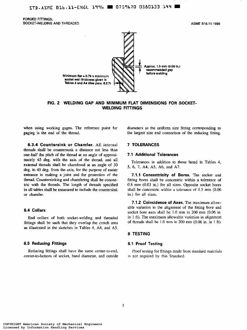
Minimum flat = 0.75 x minimum socket wail thickness given ln Tables 4 and A4 (See para. 6.2.7)
ASME 816.11-1996
Approx. 1.5 mm (0.06 in.) recommended gap before welding
FIG. 2 WELDING GAP AND MINIMUM FLAT DIMENSIONS FOR SOCKET- WELDING FllTlNGS
when using working gages. The reference point for gaging is the end of the thread.
6.3.4 Countersink or Chamfer. All internal threads shall be countersunk a distance not less than one-half the pitch of the thread at an angle of approxi- mately 45 deg. with the axis of the thread, and all external threads shall be chamfered at an angle of 30 deg. to 45 deg. from the axis, for the purpose of easier entrance in making a joint and for protection of the thread. Countersinking and chamfering shall be concen- tric with the threads. The length of threads specified in all tables shall be measured to include the countersink or chamfer.
6.4 Collars
End collars of both socket-welding and threaded fittings shall be such that they overlap the crotch area as illustrated in the sketches in Tables 4, A4, and A5.
6.5 Reducing Fittings
Reducing fittings shall have the same center-to-end, center-to-bottom of socket, band diameter, and outside
diameters as the uniform size fitting corresponding to the largest size end connection of the reducing fitting.
7 TOLERANCES
7.1 Additional Tolerances
Tolerances in addition to those listed in Tables 4, 5 , 6, 7, A4, A5, A6, and AÍ’.
7.1.1 Concentricity of Bores. The socket and fitting bores shall be concentric within a tolerance of 0.8 mm (0.03 in.) for all sizes. Opposite socket bores shall be concentric within a tolerance of 1.5 mm (0.06 in.) for all sizes.
7.1.2 Coincidence of Axes. The maximum allow- able variation in the alignment of the fitting bore and socket bore axes shall be 1.0 mm in 200 mm (0.06 in. in 1 ft). The maximum allowable variation in alignment of threads shall be 1.0 mm in 200 mm (0.06 in. in 1 ft).
8 TESTING
8.1 Proof Testing
Proof testing for fittings made from standard materials is not required by this Standard.
5
COPYRIGHT American Society of Mechanical EngineersLicensed by Information Handling ServicesCOPYRIGHT American Society of Mechanical EngineersLicensed by Information Handling Services

99
deg.
Elbo
w Cr
OSt
Tee
45
deg.
Elbo
w Co
uplin
g Hs
lf-Co
uplin
g
TABL
E 4
SOCK
ET-W
ELDI
NG
FITT
ING
S -
- Bo
re
Dia
met
er
d
F Fitti
ngs
(2)
D
CIW
S
Sock
et
Wal
l Th
ickne
ss
(1)
C
Cla
ss
Des
igna
tion
ChS
S D
esig
nstim
La
yinn
Le
ngtk
s
T
Cen
ter
to
Botto
m
of S
ocke
t -
A
v
6000
t
l- D
N
-
6
- bm.
- 3.96
iock
et
Des
igna
tion
- -
- U
om.
Bore
T t
3000
l-
Pip
e G
o. (
2)
- -
Size
q
IWO
6o
oo
8606
be
. M
in.
- -
- -
- -
‘/a
11.2
7.
6 4.
8 10
.8
6.1
3.2
3.18
3.
18
‘4
14.6
10
.0
7.1
14.2
8.
5 5.
6 3.
78
3.30
%
18.0
13
.3
9.9
17.6
11
.6
6.4
4.01
3.
50
‘/2
22.2
16
.6
12.5
7.
2 21
.8
15.0
11
.0
5.6
4.67
4.
09
- Min
. - 3.
43
Ave.
M
in.
3ow
- M
in.
- 2.41
8ow
Min
. - 3.
15
+ 8600
- M
in.
-
Dep
th
of
Sock
et
J M
in.
- mw
- 8.0
M)w
I - 8.
0
hupl
ingr
E
Hal
l Zo
uplin
gs
F
9.5
6.5
16.0
m
8 10
4.60
4.
01
3.02
3.
68
9.5
11.0
13
.5
8.0
8.0
8.5
16.0
1.
0
5.03
5.97
6.96
7.92
7.92
8.92
0.92
-
4.37
3.
20
4.01
9.
5 13
.5
15.5
8.
0 11
.0
6.5
17.5
1.
5
15
5.16
9.
35
8.18
3.
73
4.78
7.
47
9.5
15.5
19
.0
25.5
11
.0
12.5
15
.5
9.5
22.5
1.
5
20
25
%
27.6
21
.7
16.3
11
.8
27.2
20
.2
14.6
10
.3
4.90
4.
27
1 34
.3
27.4
21
.5
16.0
33
.9
25.9
19
.9
14.4
5.
69
4.98
1v4
43.1
35
.6
30.2
23
.5
42.7
34
.3
28.7
22
.0
6.07
5.
28
l'/?
49.2
41
.6
34.7
28
.7
48.8
40
.1
33.2
27
.2
6.35
5.
54
6.04
9.
78
8.56
3.
91
5.56
7.
82
12.5
19
.0
22.5
28
.5
13.0
14
.0
19.0
9.
5 24
.0
1.5
6.93
11
.38
9.96
4.
55
6.35
12
.5
22.5
27
.0
32.0
14
.0
17.5
20
.5
12.5
26
.5
2.0
32
6.93
12
.14
10.6
2 4.
85
6.35
12
.5
27.0
32
.0
35.0
17
.5
20.5
22
.5
12.5
30
.0
2.0
40
12.7
0 5.
08
12.5
32
.0
38.0
38
.0
20.5
25
.5
25.5
12
.5
32.0
2.
0
50
5.54
16
.0
38.0
25
.5
28.5
28
.5
41.0
2.
0
65
7.01
16
.0
41.0
28
.5
43.0
2.
5
60
100
-
2 61
.7
53.3
43
.6
38.9
61
.2
51.7
42
.1
37.4
6.
93
6.04
2'/2
74
.4
64.2
73
.9
61.2
6.
76
7.67
3 90
.3
79.4
89
.8
76.4
9.
52
8.30
4 11
5.7
03.8
11
5.2
00.7
IO
.69
9.35
-
- -
- -
- GE
NERA
L NO
TE:
Dime
nsion
s ar
e in
millim
eter
s.
NOTE
S:
7.80
9.50
-
13.8
4
-
11.1
2
12.1
2
-
7.62
6.56
-
7.14
8.74
-
9.09
9.70
10.1
5
11.0
7
-
16.0
57
.0
19.0
66
.5
41.0
-
54.0
-
32.0
41.0
-
19.0
19.0
19.0
19.0
44.5
2.
5
48.0
2.
5 -
- -
-
End
Wal
l Th
ickne
ss
&A
l.
3lar
rDes
ia
1.0
4.8
1.5
4.8
6.4
1.5
6.4
7.9
11.2
1.5
6.4
7.9
12.7
2.0
9.6
11.2
14
.2
2.0
9.6
11.2
14
.2
2.0
11.2
2.0
12.7
15
.7
2.5
2.5
2.5
-
15.7
19.0
22.4
-
22.4
28.4
-
(1)
Aver
age
of So
cket
Wall
Th
ickne
ss
arou
nd
perip
hery
shall
be
no
les
s tha
n lis
ted
value
s. Th
e mi
nimum
va
lues
are
perm
itted
in loc
alize
d ar
eas.
(2)
Uppe
r an
d low
er
value
s for
ea
ch
size
are
the
respe
ctive
ma
ximum
an
d mi
nimum
dim
ensio
ns.
COPYRIGHT American Society of Mechanical EngineersLicensed by Information Handling ServicesCOPYRIGHT American Society of Mechanical EngineersLicensed by Information Handling Services

FORGED FITTINGS, SOCKET-WELDING AND THREADED
90 deg. Elbow TOO Crors 41 deg. Elbow
TABLE 5 FORGED THREADED FITTINGS Center to End Elbows, Tees, I I Crosses
Nom. Pipe
DN 2000 Size
6 21 51, 8 l 14 21
15 12
44 174 32 38 1 25 33 14 20 28
10 25
40 51 15; 50 65
60 2
106 4 100 86 3 80 76 272
A
3000 21 25 28 33 38 44 51 60 64 83 95 114
-
-
6000
25 28 33 38 44 51 60 64 83 95 106 114
-
-
Center to End 45" Elbow
2000
17 17 19 22 25 28 33 35 43 52 64 79 -
GENERAL NOTE: Dimensions are in millimeters.
NOTES:
C
3000
17 19 22 25 28 33 35 43 44 52 64 79
-
-
- 6000
19 22 25 28 33 35 43 44 52 64 79 79
-
-
Outside Diameter of
- 2000
22 22 25 33 38 46 56 62 75 92
1 o9 146
-
-
Band H
3000
22 25 33 38 46 56 62 75 84 102 121 152
-
-
6000
25 33 38 46 56 62 75 84 102 121 146 152
-
-
ASME 816.11-1996
Minimum Wall Thickness
- 2000
3.18 3.18 3.18 3.18 3.18 3.68 3.89 4.01 4.27 5.61 5.99 6.55
-
-
G
3000
3.18 3.30 3.51 4.09 4.32 4.98 5.28 5.56 7.14 7.65 8.84 11.18
-
-
6000
6.35 6.60 6.98 8.15 8.53 9.93 10.59 11 .O7 12.09 15.29 16.64 18.67
-
-
Length of Thread Min. (1) - B
6.4 8.1 9.1 10.9 12.7 14.7 17.0 17.8 19.0 23.6 25.9 27.7
-
~
- 12 6.7 10.2 10.4 13.6 13.9 17.3 18.0 18.4 19.2 28.9 30.5 33.0 -
(1) Dimension B is minimum length of perfect thread. The length of useful thread (B plus threads with fully formed roots and flat crests) shall not be less than L2 (effective length of external thread) required by American National Standard for Pipe Threads (ANSUASME 81.20.1). See Section 6.3
COPYRIGHT American Society of Mechanical EngineersLicensed by Information Handling ServicesCOPYRIGHT American Society of Mechanical EngineersLicensed by Information Handling Services
ASME 816.11-1996
T i
FORGED FITTINGS, SOCKET-WELDING AND THREADED
Coupling Half-Coupling COP
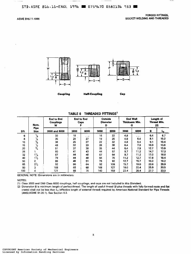
TABLE 6 THREADED FITTINGS' End to End
Thread Min. Thickness Min. Diameter Caps Couplings Length of End Wall Outside End to End
Nom. r Pipe
(21 G D P W
DN 4 B 6000 3000 6000 3000 6000 3000 3000 and 6000 Size
6
30.5 25.9 22.4 19.0 127 108 68 65 108 3 80 28.9 23.6 19.0 15.7 108 92 64 60 92 2'/2 65 19.2 19.0 15.7 12.7 92 76 51 48 86 2 50 18.4 17.8 12.7 11.2 76 64 48 44 79 1 Y* 40 18.0 17.0 11.2 9.7 64 57 46 44 67 1 '/4 32 17.3 14.7 11.2 9.7 57 44 43 41 60 1 25
20 13.6 10.9 7.9 6.4 38 28 33 32 48 '12 15
10 8
6.7 6.4 . . . 4.8 22 16 . . . 19 32 '/a
1 O0 4 121 68 75 140 159 22.4 28.4 27.7 33.0
1
3 14
13.9 12.7 7.9 6.4 44 35 38 37 51 14
10.4 9.1 6.4 4.8 32 22 27 25 38 /a 10.2 8.1 6.4 4.8 25 19 27 25 ' 35
3
GENERAL NOTE: Dimensions are in millimeters.
NOTES: (1) Class 2000 and DN6 Class 6000 couplings, half couplings, and caps are not included in this Standard. (2) Dimension B is minimum length of perfect thread. The length of useful thread (B plus threads with fully formed roots and flat
crests) shall not be less than L2 (effective length of external thread) required by American National Standard for Pipe Threads (ANWASME BI .20.1). See Section 6.3.
8
COPYRIGHT American Society of Mechanical EngineersLicensed by Information Handling ServicesCOPYRIGHT American Society of Mechanical EngineersLicensed by Information Handling Services

FORGED FITTINGS, SOCKET-WELDING AND THREADED
DN
6 8
10 15 20 25 32 40 50 65 80
1 O0
-f i
Square Heed Hex Head Round Head Plug Plug Plug
Nominal
A Size (Minimum) Pipe
Length
'18
'12
13 "/B 11 '14
10
21 1 5; 21 1 '14 19 1 16 14
14
2 ?; 27
3
2
32 4 28 3
22
ASME 816.11-1996
TABLE 7 PLUGS AND BUSHINGS
Hex Head Flush Bushing Bushing
[See Note (la
Plugs Square Head
Height of Width Square
C B (Minimum) (Minimum)
Flats
6 7 6 10 8 11
10 14 11 16 13
65 25 41 21 36 19 32 18 28 16 24 14 21
Plugs Round Head
Nominal Diameter
(Minimum) of Head Length
E D
10 35 14 41 18 41 21 44 27
76 114 70 89 70 73 64 60 51 ' 48 51 43 51 33 44
Width Flats
(Nominal) F
11 16 18 22 27 36 46 50 65 75 90
115
Hex Plugs and Bushings I
Hex Height (Min.)
Bushing Plug G H
. . . 6 3
25 13 21 10 19 10 18 9 16 8 14 7 10 6 10 6 8 5 8 4 6
GENERAL NOTE: Dimensions are in millimeters.
NOTE: (1) Cautionary Note Regarding Hex Bushings. Hex Head Bushings of one-size reduction should not be used in services wherein
they might be subject to harmful loads and forces other than internal pressures.
9
COPYRIGHT American Society of Mechanical EngineersLicensed by Information Handling ServicesCOPYRIGHT American Society of Mechanical EngineersLicensed by Information Handling Services

ASME 816.11-1996
ANNEX A INCH TABLES
(This Annex is an integral part of ASME 616.11-1996 and is placed after the main text for convenience. See para. 1.5.)
This Annex provides tables of the standard inch dimensions for fittings.
11
COPYRIGHT American Society of Mechanical EngineersLicensed by Information Handling ServicesCOPYRIGHT American Society of Mechanical EngineersLicensed by Information Handling Services

‘90
deg.
Elbo
w Cr
oar
’ Te
e ’
45
deg.
Elbo
w Co
uplin
g Ha
lf-Co
uplin
g Ca
p
TABL
E A4
SO
CKE
T-W
ELD
ING
FI
TTIN
GS
Body
W
all
G
End
Wal
l Th
ickne
ss
klh.
Cen
ter
to
Botto
m
of
Sock
et
-A
90"
Elbo
ws.
Te
es,s
ndC
ross
er
45*E
lbow
s Cl
sss
Des
igna
tion
Dep
th
of
iOOk
U J M
in.
Sock
e Bo
re
Dia
. (2
a
6ooo
- M
in.
Cla
ss
Des
igne
tion
Hal
f Zo
uplin
g:
F P
ipe
Size
90
00
Ave.
0.12
5
t
0.14
6
0.15
6
- Min
. - 0.
125
- Min
. - 0.
13:
Min
. -
Min
. M
in.
A
E
0.44
0 0.
299
0.16
! 0.
420
0.23
9 0.
121
0.57
5 0.
394
0.26
1 0.
555
0.33
4 0.
221
0.71
0 0.
523
0.W
0.
690
0.46
3 0.
32:
0.67
5 0.
652
0.49
d 0.
655
0.59
2 0.
4%
0.09
5 0.
124
0.36
0.
25
0.62
0.
03
0.06
0.13
c 0.
161
0.15
t 0.
119
0.14
5 0.
36
0.44
0.
52
0.31
0.
25
0.62
0.
03
0.05
0.13
8 0.
19E
0.17
2 0.
126
0.15
6 0.
36
0.53
0.
62
0.31
0.
25
0.69
0.
05
0.12
;:z;
0.16
4 0.
161
0.23
5 0.
204
0.36
8 1.
322
0.14
7 0.
166
0.29
4
0.30
6
0.35
6
0.36
2
0.40
0
0.43
6
0.36
0.
62
0.75
1.
00
0.44
0.
62
0.36
0.
66
0.06
0.
12
1.06
5 0.
654
0.64
; 1.
065
0.79
4 0.
56;
1.35
0 1.
079
0.64
I 1.
330
1.01
9 0.
76E
1.69
5 1.
410
1.19
L 1.
675
1.35
0 1.
131
1.93
5 1.
640
1.36
E 1.
915
1.56
0 1.
308
0.16
6 0.
274
0.36
5 I.3
37
0.15
4 0.
219
0.50
0.
75
0.66
1.
12
0.54
0.
56
0.75
0.69
0.
61
0.61
0.
66
1.00
1.
00
0.36
0.50
0.50
0.50
0.75
0.75
0.75
0.75
0.94
0.
06
0.12
0.19
6 0.
312
0.31
2
0.35
1
0.27
3 0.
448
I.392
0.
179
0.26
0 0.
50
0.66
1.
06
1.25
0.
56
1.12
0.
06
0.16
0.20
8 0.
273
0.47
6 I.4
16
0.19
1 0.
250
0.50
1.
06
1.25
0.21
6 0.
500
0.54
5
I.436
I.477
-
0.20
0 0.
261
0.50
1.
25
1.50
2.42
6 2.
097
1.71
7 2.
406
2.03
7 1.
657
2.93
1 2.
529
2.90
6 2.
409
3.56
0 3.
126
3.53
5 3.
006
4.57
0 4.
066
4.64
6 3.
986
0.23
6
0.30
2
0.32
7
0.36
6 -
0.43
0 0.
216
0.34
4 0.
62
1.50
1.
62
1.36
1.50
2.12
0.69
1.
19
0.61
1.
25
0.06
0.
16
0.06
0.
16
i.m
1.12
1.
62
3.27
6 0.
62
1.12
0.37
5 1.
300
I.337
-
0.62
1.62
2.25
1.
25
IO.4
21
0.75
2.
62
- 1.
62
1.12
-
1.69
1.75
1.66
0.06
0.
16
0.06
0.
50
0.62
0.10
0.
20
0.10
0.
62
0.75
0.10
0.
20
0.10
0.
75
0.66
0.10
0.
20
0.10
0.
86
1.12
GENE
RAL
NOTE
: Di
men
sions
ar
e in
inch
es.
NOTE
S:
(1)
Aver
age
of S
ocke
t W
all T
hick
ness
ar
ound
pe
riphe
ry
shall
be
no l
ess
than
lis
ted
valu
es.
The
min
imum
va
lues
ar
e pe
rmitt
ed
in loc
alize
d ar
eas.
(2
) Up
per
and
lower
va
lues
fo
r ea
ch s
ize a
re t
he r
espe
ctive
m
axim
um
and
min
imum
di
men
sions
.
0.25
0.25
0.25
0.06
0.
25
0.31
0.06
0.
36
0.44
0.06
0.
38
0.44
0.06
0.
44
0.50
0.
62
COPYRIGHT American Society of Mechanical EngineersLicensed by Information Handling ServicesCOPYRIGHT American Society of Mechanical EngineersLicensed by Information Handling Services
STD-ASME B L b * L L - E N G L 377b W 0757b70 0580340 384 m
FORGED FITTINGS, SOCKET-WELDING AND THREADED
Nom. Pipe Size
'18 '14
3/8 5;
14
1 '14
1 5;
2 72
3
1
2
3 4
- 2000
0.81 0.81 0.97 1.12
1.31 1.50 1.75 2.00
2.38 3.00 3.38 4.19
L A 4 \
BO dog. Elbow T- Cross 45 dog. Elbow
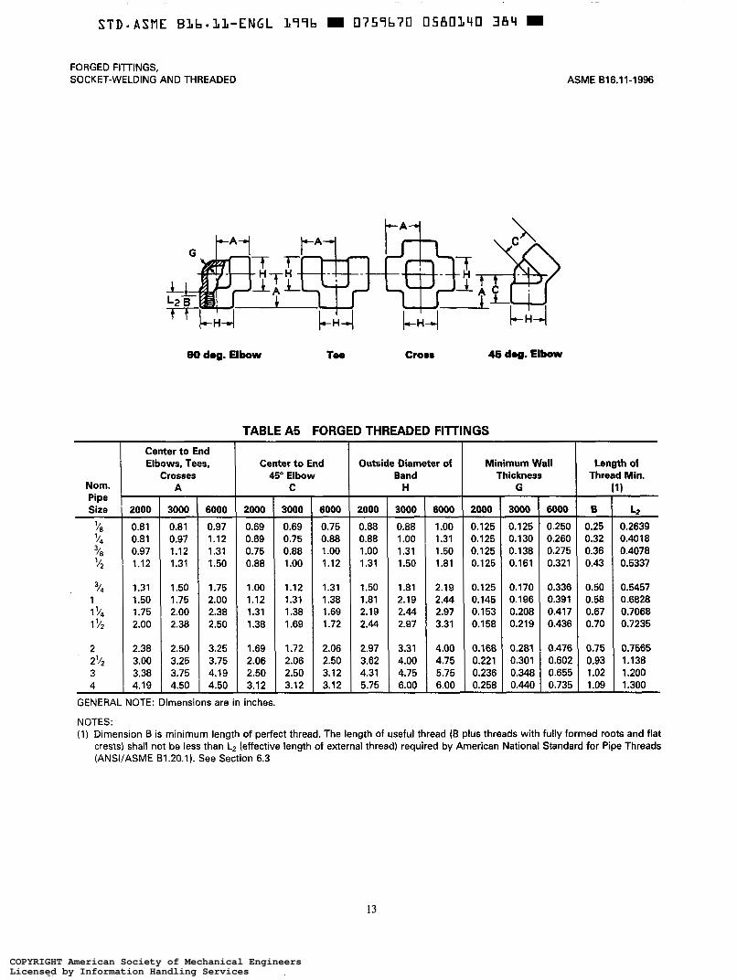
TABLE A5 FORGED THREADED FllTlNGS Center to End Elbows, Tees,
Crosses A
3000 6000
0.81 0.97 0.97
1.50 1.31 1.31 1.12 1.12
1.50 1.75 1.75 2.00 2.00 2.38 2.38 2.50
2.50 3.25 3.25 3.75 3.75 4.19 4.50 4.50
Center t o End Outside Diameter of
2000
0.69 0.69 0.75 0.88
1 .o0 1.12 1.31 1.38
1.69 2.06 2.50 3.12
45" Elbow I C
3000
0.69 0.75 0.88 1 .o0
1.12 1.31 1.38 1.69
1.72 2.06 2.50 3.1 2
6000 2000
0.75 0.88 0.88
1.31 1.12 1.00 1.00 0.88
1.31
2.44 1.72 2.19 1.69 1.81 1.38 1.50
2.06 2.97 2.50 3.62 3.12 4.31 3.12 5.75
Band H
3000 0.88 1 .o0 1.31 1.50
1 .a1 2.19 2.44 2.97
3.31 4.00 4.75 6.00
- 6ooo 1 .o0 1.31 1.50 1.81
2.19 2.44 2.97 3.31
4.00 4.75 5.75 6.00
ASME 816.11-1996
Minimum Wall Thickness
2000
0.125 0.1 25 0.125 0.125
O. 125 0.145 0.153 0.1 58
0.168 0.221 0.236 0.258
G
3000 6000
0.125 ' 0.250 0.130
0.321 0.161 0.275 0.138 0.260
0.170 0.336 O. 196 0.391 0.208 0.417 0.2 19 0.436
0.281 0.476 0.301 0.602 0.348 0.655 0.440 0.735
Length of Thread Min.
- B
0.25 0.32 0.36 0.43
0.50 0.58 0.67 0.70
0.75 0.93 1 .o2 1 .o9 -
1
L2 0.2639 0.40 18 0.4078 0.5337
0.5457 0.6828 0.7068 0.7235
0.7565 1.138 1.200 1.300
GENERAL NOTE: Dimensions are in inches.
NOTES: (1) Dimension B is minimum length of perfect thread. The length of useful thread (B plus threads with fully formed roots and flat
crests) shall not be less than L2 (effective length of external thread) required by American National Standard for Pipe Threads (ANWASME 81.20.1). See Section 6.3
13
COPYRIGHT American Society of Mechanical EngineersLicensed by Information Handling ServicesCOPYRIGHT American Society of Mechanical EngineersLicensed by Information Handling Services

ASME B16.11-1996
Nom. Pipe Size
10 94 /a '/2
4
1 Y4 1 '/2
292
1
3
3
1
2
3 4
FORGED FITTINGS, SOCKET-WELDING AND THREADED
Coupling Half-Coupling COP
TABLE A6 THREADED FllTlNGS (1)
End t o End Couplings
W
3000 and 6000
1.25 1.38 1.50 1.88
2.00 2.38 2.62 3.1 2
3.38 3.62 4.25 4.75
End to End Caps
P
3000 6000
0.75 1 .o0 1 .O6 1 .o0 1 .O6 1.25 1.31
1.44 1.50 1.62 1.69 1.75 1.81 1.75 1.88
1 .88 2.00 2.38 2.50 2.56 2.69 2.69 2.94
. . .
~~
Outside End Wall Diameter I T h i c k n y Min. D
3000 0.62 0.75 0.88 1.12
1.38 1.75 2.25 2.50
3.00 3.62 4.25 5.50
6000 3000
0.88 0.19 1 .o0
0.25 1.50 0.19 1.25 0.19
1.75 0.25 2.25 0.38 2.50 0.38 3.00 0.44
3.62 0.50 4.25 0.62 5.00 0.75 6.25 0.88
6000
. . . 0.25 0.25 0.31
0.31 0.44 0.44 0.50
0.62 0.75 0.88 1.12
T Length of Thread Min. (21
B
0.25 0.32 0.36 0.43
0.50 0.58 0.67 0.70
0.75 0.93 1 .o2 1 .o9
. .
12 0.2639 0.40 18 0.4078 0.5337
0.5457 0.6828 0.7068 0.7235
0.7565 1.138 1.200 1.300
GENERAL NOTE: Dimensions are in inches.
NOTES: (1) Class 2000 and DN6 Class 6000 couplings, half couplings, and caps are not included in this Standard. (2) Dimension B is minimum length of perfect thread. The length of useful thread (B plus threads with fully formed roots and flat
crests) shall not be less than L2 (effective length of external thread) required by American National Standard for Pipe Threads (ANSVASME 81.20.1). See Section 6.3
14
COPYRIGHT American Society of Mechanical EngineersLicensed by Information Handling ServicesCOPYRIGHT American Society of Mechanical EngineersLicensed by Information Handling Services

FORGED FITTINGS, SOCKET-WELDING AND THREADED ASME 616.11-1996
Square Head Hex Head Round Head Hex Heed Plug Plug Plug Bushing Bushing
Fluah
@o0 Note clfl
TABLE A7 PLUGS AND BUSHINGS
Nominal Pipe Size
Length (Minimum)
A
0.38 0.44 0.50 0.56
0.62 0.75 0.81 0.81
0.88 1 .O6 1.12 1.25
Plugs Square Head Hex Plugs and Bushings Plugs Round Head
Height of Square
(Minimum) B
0.25 0.25 0.31 0.38
0.44 0.50 0.56 0.62
0.69 0.75 0.81 1 .o0 L
GENERAL NOTE: Dimensions are in inches.
I Width
(Minimum) Diameter Flats Nominal
of Head C E
0.28 0.41 0.38 0.53 O .44 O .69 0.56 0.84
0.62 1 .O6 0.81 1.31 0.94 1.69 1.12 1.91
1.31 2.38 1.50 2.88 1.69 3.50 2.50 4.50
(Minimum) 1 (Nominal) 1 Buzing D F
1.38 1.62 1.62 1.75
1.75 2.00 2.00 2.00
0.44 0.62 0.12 0.69
0.19 0.88 0.16
1 .O6 0.22 1.38 0.25 1.75 0.28 2.00 0.31
. . .
(Min.)
Plug H
0.25 0.25 0.31 0.31
0.38 0.38 0.56 0.62
0.69 0.75 0.81 1 .o0
NOTE: (1) Cautionary Note Regarding Hex Bushings. Hex Head Bushings of one-size reduction should not be used in services wherein
they might be subject to harmful loads and forces other than internal pressures.
15
COPYRIGHT American Society of Mechanical EngineersLicensed by Information Handling ServicesCOPYRIGHT American Society of Mechanical EngineersLicensed by Information Handling Services

ANNEX B METHOD FOR BURST TESTING FlITlNGS
(This Annex is an integral part of ASME 816.11-1996 and is placed after the main text for convenience. See para. 5.2.)
B1 This Annex is included to provide documentation of design requirements for nonstandard materials as a service to users of this Standard (see para. 5.2).
B2 Such fittings whose design cannot be established by mathematical analyses contained in nationally recog- nized pressure vessel or piping codes may be established by proof testing in accordance with Section B3.
B3 To insure adequacy of fittings design, the actual bursting strength of fittings shall not be less than the computed bursting strength of the pipe of the designated schedule number and material. To determine the relative strength of the fitting, straight pipe of the designated wall thickness and material shall be welded to each end of the socket-welding fitting or threaded into each end of the threaded end fitting, 153 mm (6.0 in.) in length but not less than twice the outside diameter of the pipe, and with proper end closures applied beyond the minimum length of straight pipe. Hydrostatic pres- sure shall be applied until at least the computer bursting pressure is achieved.
The computed bursting strength of pipe shall be determined on the basis of the following formula:
2SFt p z - D
where P = computed bursting strength of pipe gage
pressure S = specification minimum ultimate tensile strength
of pipe material F = 1.125, which is a factor to adjust test pressure
for the actual tensile strength of the test piece
= 0.90 x nominal thickness in sizes DN 32 (1 '/4 = 0.93 x nominal thickness in sizes DN 40 (l'/z
t = pipe wall thickness
in.) and less
in.) and larger D = outside diameter of pipe
(NOTE Any dimensionally consistent system may be used.)
Since the above formula is applicable only to straight pipe it cannot be used for a direct computation of the bursting strength of fittings. The fittings ability to withstand bursting shall be gaged only by comparing their behavior on test with the calculated bursting strength of straight pipe of the designated wall thickness and material.
17
COPYRIGHT American Society of Mechanical EngineersLicensed by Information Handling ServicesCOPYRIGHT American Society of Mechanical EngineersLicensed by Information Handling Services

STD-ASME BLb=LL-ENGL L97b m 0757b70 0580344 T Z T m
ANNEX C QUALITY SYSTEM PROGRAM
(This Annex is not a part of ASME 616.11-1996 and is included for information purposes only.)
The products manufactured in accordance with this Standard shall be produced under a quality system program following the principles of an appropriate standard from the IS0 9000 series’. A determination of the need for registration andor certification of the product manufacturer’s quality system program by an independent organization shall be the responsibility of the manufacturer. The detailed documentation demon- strating program compliance shall be available to the purchaser at the manufacturer’s facility. A written sum- mary description of the program utilized by the product manufacturer shall be available to the purchaser upon request. The product manufacturer is defined as the entity whose name or trademark appears on the product in accordance with the marking or identification require- ments of this Standard.
The series is also available from the American National Standards Institute (ANSI) and the American Society for Quality Control (ASQC) as American National Standards that are identified by a prefix “Q” replacing the prefix “ISO’. Each standard of the series is listed under references.
19
COPYRIGHT American Society of Mechanical EngineersLicensed by Information Handling ServicesCOPYRIGHT American Society of Mechanical EngineersLicensed by Information Handling Services
ASME Bl6.11-1996
ANNEX D REFERENCES
(This Annex is an integral part of ASME 816.11-1996 and is placed after the main text for convenience.)
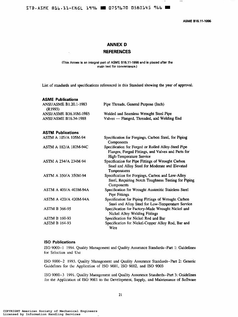
List of standards and specifications referenced in this Standard showing the year of approval.
ASME Publications ANSUASME B1.20.1-1983
(R1993) ANSUASME B36.10M-1985 ANSVASME B16.34-1988
ASTM Publications ASTM A 105/A 105M-94
ASTM A 182/A 182M-94C
ASTM A 234/A 234M-94
ASTM A 350/A 350M-94
ASTM A 403/A 403M-94A
ASTM A 420lA 420M-94A
ASTM B 366-95
ASTM B 160-93 ASTM B 164-93
Pipe Threads, General Purpose (Inch)
Welded and Seamless Wrought Steel Pipe Valves - Flanged, Threaded, and Welding End
Specification for Forgings, Carbon Steel, for Piping
Specification for Forged or Rolled Alloy-Steel Pipe Components
Flanges, Forged Fittings, and Valves and Parts for High-Temperature Service
Steel and Alloy Steel for Moderate and Elevated Temperatures
Specification for Forgings, Carbon and Low-Alloy Steel, Requiring Notch Toughness Testing for Piping Components
Pipe Fittings
Steel and Alloy Steel for Low-Temperature Service
Nickel Alloy Welding Fittings
Specification for Pipe Fittings of Wrought Carbon
Specification for Wrought Austenitic Stainless Steel
Specification for Piping Fittings of Wrought Carbon
Specification for Factory-Made Wrought Nickel and
Specification for Nickel Rod and Bar Specification for Nickel-Copper Alloy Rod, Bar and
Wire
IS0 Publications IS0 9000-1 1994. Quality Management and Quality Assurance Standards-Part 1: Guidelines for Selection and Use
I S 0 9000-2 1993. Quality Management and Quality Assurance Standards-Part 2: Generic Guidelines for the Application of I S 0 9001, IS0 9002, and IS0 9003
IS0 9000-3 1991. Quality Management and Quality Assurance Standards-Part 3: Guidelines for the Application of IS0 9001 to the Development, Supply, and Maintenance of Software
COPYRIGHT American Society of Mechanical EngineersLicensed by Information Handling ServicesCOPYRIGHT American Society of Mechanical EngineersLicensed by Information Handling Services

ASME 618.11-1996 FORGED FIlTINGS,
SOCKET-WELDING AND THREADED
IS0 9001 -1994. Quality Systems: Model for Quality Assurance in Design, Development, Production, Installation, and Servicing
IS0 9002-1994. Quality Systems: Model for Quality Assurance in Production and Servicing
IS0 9003- 1994. Quality Systems: Model for Quality Assurance in Final Inspection and Test
Publications of the following organizations appear on the above list:
ASME
ASTM
IS0
The American Society of Mechanical Engineers 345 East 47th Street, New York, NY 10017 American Society for Testing and Materials 100 Barr Harbor Drive, West Conshohocken, PA 19428 IS0 Central Secretariat Case Postale 56 CH-121 1 Geneva 20 Switzerland/Suisse
Publications appearing above which have been approved as American National Standards may also be obtained from:
ANSI American National Standards Institute, Inc. 11 West 42nd Street, New York, NY 10036
22
COPYRIGHT American Society of Mechanical EngineersLicensed by Information Handling ServicesCOPYRIGHT American Society of Mechanical EngineersLicensed by Information Handling Services
STD-ASME B L b = L L - E N G L L99b D 0759b70 0580147 739 m
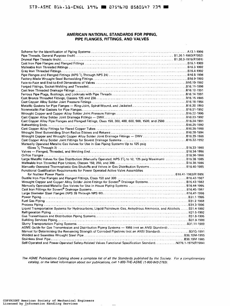
AMERICAN NATIONAL STANDARDS FOR PIPING, PIPE FLANGES, FITTINGS, AND VALVES
The ASME Publications Catalog shows a complete list of all the Standards published by the Society. For a complimentary catalog, or the latest information about our publications, call 1-800-THE-ASME (1-800-843-2763).
COPYRIGHT American Society of Mechanical EngineersLicensed by Information Handling ServicesCOPYRIGHT American Society of Mechanical EngineersLicensed by Information Handling Services