azur 840A V2 - EXCELIA HIFI · PDF fileAmplifier. We hope that you ... Cambridge Audio...
16
Class XD integrated amplifier User’s manual 2 840A V2 azur ENGLISH
Transcript of azur 840A V2 - EXCELIA HIFI · PDF fileAmplifier. We hope that you ... Cambridge Audio...
Class XD integrated amplifierUser’s manual
2
840A V2azur
ENG
LIS
H

Thank you for purchasing this Azur 840A V2 Class XD IntegratedAmplifier. We hope that you will enjoy many years of listening pleasurefrom it.
The 840A V2 features our unique proprietary amplifier topology; ClassXD™ , designed to eliminate crossover distortion at low signal levels.
By actively displacing the crossover point this technology creates aregion of pure Class-A operation where the crossover zone wouldotherwise be before moving into an enhanced form of Class B at higherlevels. It should not be confused with Class AB, which gives a small areaof Class A, but at the cost of higher distortion as soon as the signal levelmoves outside the AB area. Class XD circuitry not only removescrossover distortion from the zero-crossing point but also reducesdistortion in the other parts of the amplifier's output range.
This V2 version of the 840A features our latest development of Class XDwith many tweaks and enhancements from our on-going researchresulting in our best sounding implementation to date.
A white paper on this patent pending technology is available on ourwebsite: www.cambridge-audio.com
Please note that because of the Class XD technology the 840A V2 runsslightly warmer than a conventional Class B/AB amplifier and theventilation slots on the top of the unit must not be obstructed.
Other features include the use of precision resistor ladders switched bygold plated relay contacts for the volume and balance controls ratherthan the more common solid-state or volume potentiometer schemes.Volume is controllable in 1 dB steps over most of the range, giving veryfine control, an accurate logarithmic law and superbly accurate channelbalance. Input switching is also by high quality gold contact relays.
The 840A V2 features separate transformer secondaries for left andright channels, twin rectifiers and separate PSU's for dual monooperation of the left and right power amplifiers. A separate transformersupplies the preamp making the 840A V2 effectively a Pre and Poweramp combination in one box.
Input 1 features a balanced input using XLRs giving optimalperformance with equipment such as the matching 840C UpsamplingCD player which features balanced outputs.
The casework combines massive structural rigidity with careful dampingand control of acoustic resonance. An Azur Navigator remote control isalso provided, giving full remote control of your amplifier in an attractiveand easy to use handset.
We have also included support for multi-room use. By plugging in one ortwo external Cambridge Audio Incognito keypads and a power supplyunit your amplifier can become the hub of a simple multi-room system.In addition, Control Bus Input/Output, IR Emitter Input and RS232control are featured making it easy to integrate the 840A V2 into aCustom Installation system if desired.
Your amplifier can only be as good as the system it is connected to.Please do not compromise on your source equipment, speakers orcabling. Naturally we particularly recommend models from theCambridge Audio Azur range. These have been designed to the sameexacting standards as this amplifier. Your dealer can also supplyexcellent quality Cambridge Audio interconnects to ensure your systemrealises its full potential.
Thank you for taking the time to read this manual; we do recommendyou keep it for future reference.
Matthew Bramble,Cambridge Audio Technical Director and the Amplifier design team
2
Contents Introduction
Introduction .................................................................................................2
Limited warranty..........................................................................................3
Safety precautions ......................................................................................3
Important safety instructions .....................................................................4
Rear panel connections..............................................................................5
Front panel controls ...................................................................................6
Remote control ............................................................................................7
iPod compatibility........................................................................................7
Connections ................................................................................................8
Operating instructions ..............................................................................10
Amplifier setup ..........................................................................................10
Multi-Room connections ..........................................................................12
Custom installation use............................................................................13
CAP5 protection system ...........................................................................14
Troubleshooting.........................................................................................15
Technical Specifications...........................................................................15

3
840A V2azur
ENG
LIS
HCambridge Audio warrants this product to be free from defects inmaterials and workmanship (subject to the terms set forth below).Cambridge Audio will repair or replace (at Cambridge Audio's option) thisproduct or any defective parts in this product. Warranty periods may varyfrom country to country. If in doubt consult your dealer and ensure thatyou retain proof of purchase.
To obtain warranty service, please contact the Cambridge Audio authoriseddealer from which you purchased this product. If your dealer is notequipped to perform the repair of your Cambridge Audio product, it can bereturned by your dealer to Cambridge Audio or an authorised CambridgeAudio service agent. You will need to ship this product in either its originalpackaging or packaging affording an equal degree of protection.
Proof of purchase in the form of a bill of sale or receipted invoice, whichis evidence that this product is within the warranty period, must bepresented to obtain warranty service.
This Warranty is invalid if (a) the factory-applied serial number has beenaltered or removed from this product or (b) this product was notpurchased from a Cambridge Audio authorised dealer. You may callCambridge Audio or your local country Cambridge Audio distributor toconfirm that you have an unaltered serial number and/or you purchasedfrom a Cambridge Audio authorised dealer.
This Warranty does not cover cosmetic damage or damage due to acts ofGod, accident, misuse, abuse, negligence, commercial use, or modificationof, or to any part of, the product. This Warranty does not cover damage dueto improper operation, maintenance or installation, or attempted repair byanyone other than Cambridge Audio or a Cambridge Audio dealer, orauthorised service agent which is authorised to do Cambridge Audiowarranty work. Any unauthorised repairs will void this Warranty. ThisWarranty does not cover products sold AS IS or WITH ALL FAULTS.
REPAIRS OR REPLACEMENTS AS PROVIDED UNDER THIS WARRANTY ARETHE EXCLUSIVE REMEDY OF THE CONSUMER. CAMBRIDGE AUDIO SHALLNOT BE LIABLE FOR ANY INCIDENTAL OR CONSEQUENTIAL DAMAGES FORBREACH OF ANY EXPRESS OR IMPLIED WARRANTY IN THIS PRODUCT.EXCEPT TO THE EXTENT PROHIBITED BY LAW, THIS WARRANTY IS EXCLUSIVEAND IN LIEU OF ALL OTHER EXPRESS AND IMPLIED WARRANTIESWHATSOEVER INCLUDING, BUT NOT LIMITED TO, THE WARRANTY OFMERCHANTABILITY AND FITNESS FOR A PRACTICAL PURPOSE.
Some countries and US states do not allow the exclusion or limitation ofincidental or consequential damages or implied warranties so the aboveexclusions may not apply to you. This Warranty gives you specific legalrights, and you may have other statutory rights, which vary from state tostate or country to country.
Plug Fitting Instructions (UK Only)
The cord supplied with this appliance is factory fitted with a UK mains plug fittedwith a 5 amp fuse inside. If it is necessary to change the fuse, it is important thata 5 amp one is used. If the plug needs to be changed because it is not suitable foryour socket, or becomes damaged, it should be cut off and an appropriate plugfitted following the wiring instructions below. The plug must then be disposed ofsafely, as insertion into a mains socket is likely to cause an electrical hazard.Should it be necessary to fit a 3-pin BS mains plug to the power cord the wiresshould be fitted as shown in this diagram. The colours of the wires in the mainslead of this appliance may not correspond with the coloured markings identifyingthe terminals in your plug. Connect them as follows:
The wire which is coloured BLUE must beconnected to the terminal which is markedwith the letter ‘N’ or coloured BLACK.
The wire which is coloured BROWN must beconnected to the terminal which is markedwith the letter ‘L’ or coloured RED.
The wire which is coloured GREEN/YELLOWmust be connected to the terminal which ismarked with the letter ‘E’ or coloured GREEN.
If your model does not have an earth wire,then disregard this instruction.
If a standard 13 amp (BS 1363) plug is used, a 5 amp fuse must be fitted, or if anyother type of plug is used a 5 amp fuse must be fitted, either in the plug or adaptor,or on the distribution board.
Checking the Power Supply RatingFor your own safety please read the following instructions carefully beforeattempting to connect this unit to the mains.
Check that the rear of your unit indicates the correct supply voltage. If your mainssupply voltage is different, consult your dealer.
This unit is designed to operate only on the supply voltage and type that isindicated on the rear panel of the unit. Connecting to other power sources maydamage the unit.
This equipment must be switched off when not in use and must not be used unlesscorrectly earthed. To reduce the risk of electric shock, do not remove the unit's cover(or back). There are no user serviceable parts inside. Refer servicing to qualifiedservice personnel. If the power cord is fitted with a moulded mains plug the unit mustnot be used if the plastic fuse carrier is not in place. Should you lose the fuse carrierthe correct part must be reordered from your Cambridge Audio dealer.
The lightning flash with the arrowhead symbol within an equilateral triangleis intended to alert the user to the presence of un-insulated ‘dangerousvoltage’ within the product’s enclosure that may be of sufficientmagnitude to constitute a risk of electric shock to persons.
The exclamation point within an equilateral triangle is intended to alertthe user to the presence of important operating and maintenanceinstructions in the service literature relevant to this appliance.
The crossed-out wheeled bin is the European Union symbol forindicating separate collection for electrical and electronicequipment. This product contains electrical and electronicequipment which should be reused, recycled or recovered andshould not be disposed of with unsorted regular waste. Pleasereturn the unit or contact the authorised dealer from whom youpurchased this product for more information.
ApprovalsThis product complies with European Low Voltage (73/23/EEC)and Electromagnetic Compatibility (89/336/EEC) Directiveswhen used and installed according to this instruction manual.For continued compliance only Cambridge Audio accessoriesshould be used with this product and servicing must be referredto qualified service personnel.
NOTE: THE MANUFACTURER IS NOT RESPONSIBLE FOR ANY RADIO OR TVINTERFERENCE CAUSED BY UNAUTHORIZED MODIFICATIONS TO THISEQUIPMENT. SUCH MODIFICATIONS COULD VOID THE USER AUTHORITY TOOPERATE THE EQUIPMENT.
This equipment has been tested and found to comply with the limits for a Class Bdigital device, pursuant to Part 15 of the FCC Rules. These limits are designed toprovide reasonable protection against harmful interference in a residentialinstallation. This equipment generates, uses and can radiate radio frequencyenergy and, if not installed and used in accordance with the instructions, maycause harmful interference to radio communications. However, there is noguarantee that interference will not occur in a particular installation.
If this equipment does cause harmful interference to radio or television reception,which can be determined by turning the equipment off and on, the user isencouraged to try to correct the interference by one or more of the followingmeasures:
- Re-orient or relocate the receiving antenna.
- Increase the separation between the equipment and receiver.
- Connect the equipment into an outlet on a circuit different from that to which thereceiver is connected.
- Consult the dealer or an experienced radio/TV technician for help.
Safety precautionsLimited warranty
4
Important safety instructions
Please take a moment to read these notes before installing your 840AV2, as they will enable you to get the best performance and prolong thelife of the unit. We advise you follow all instructions, heed all warningsand keep the instructions for future reference.
VentilationIMPORTANT - The unit will become hot when in use.
Please ensure there is ample ventilation (at least 10cm clearance allround). Do not put any objects on top of this unit. Do not situate it on arug or other soft surface and do not obstruct any air inlets or outletgrilles. Do not install near any heat sources such as radiators, heatregisters, stoves, or other apparatus (including amplifiers) that produceheat. Do not stack multiple units on top of each other. Do not place inan enclosed area such as a bookcase or in a cabinet without sufficientventilation.
Ensure that small objects do not fall through any ventilation grille. If thishappens, switch off immediately, disconnect from the mains supply andcontact your dealer for advice.
PositioningChoose the installation location carefully. Avoid placing it in directsunlight or close to a source of heat. Also avoid locations subject tovibration and excessive dust, cold or moisture. Do not place the unit onan unstable surface or shelf. The unit may fall, causing serious injury toa child or adult as well as serious damage to the product. Do not placeother equipment on top of the unit.
This unit must be installed on a sturdy, level surface. Do notplace in a sealed area such as a bookcase or in a cabinet. Anyspace open at the back (such as a dedicated equipment rack)is fine however. When a cart is used, use caution when movingthe cart to avoid injury from tip-over.
Due to stray magnetic fields turntables or CRT TV’s should not belocated nearby due to possible interference.
WARNING - To reduce the risk of fire or electric shock, do not expose thisunit to rain or moisture. This unit must not be used near water orexposed to dripping or splashing water or other liquids. No objects filledwith liquid, such as vases, shall be placed on the unit. In the event,switch off immediately, disconnect from the mains supply and contactyour dealer for advice.
Electronic audio components have a running in period of around a week(if used several hours per day). This will allow the new components tosettle down, the sonic properties will improve over this time.
Grounding and polarisationDo not defeat the safety purpose of the polarized or grounding type plug.A polarized plug has two blades with one wider than the other. Agrounding type plug has two blades and a third grounding prong. Thewide blade or third prong are provided for your safety. If the providedplug does not fit your outlet, consult an electrician for replacement ofthe obsolete outlet.
Power sources The unit is of Class 1 construction and must be connected to a Mainssocket outlet with a protective earthing connection.
The unit should be operated only from the type of power sourceindicated on the marking label. If you are not sure of the type of power-supply to your home, consult your product dealer or local PowerCompany.
This unit has been designed to be left in Standby mode when not in use,this will increase the life of the amplifier (this is true with all electronicequipment). To turn the unit off completely switch off on the rear panel.If you do not intend to use this unit for a long period of time, unplug itfrom the mains socket.
Power cord protectionThe unit must be installed in a manner that makes disconnection of themains plug from the mains socket outlet (or appliance connector from therear of the unit) possible. Where the mains plug is used as the disconnectdevice, the disconnect device shall remain readily operable. Protect thepower cord from being walked on or pinched particularly at plugs,convenience receptacles, and the point where they exit from the unit.
Be sure to insert each power cord securely. To prevent hum and noise, donot bundle the interconnect leads with the power cord or speaker leads.
Overloading Do not overload wall outlets or extension cord as this can result in a riskof fire or electric shock. Overloaded AC outlets, extension cords, frayedpower cords, damaged or cracked wire insulation, and broken plugs aredangerous. They may result in a shock or fire hazard.
Lightning For added protection during a thunderstorm, or when it is leftunattended and unused for long period of time, unplug the unit from thewall outlet and disconnect the antenna or cable system. This will preventdamage to the unit from lightning and power-line surges.
CleaningTo clean the unit, wipe its case with a dry, lint-free cloth. Do not use anycleaning fluids containing alcohol, ammonia or abrasives. Do not sprayan aerosol at or near the amplifier.
AttachmentsDo not use attachments not recommended by your dealer as they maycause harm to the unit. Only use the specified attachments/accessorieswith this unit.
Servicing These units are not user serviceable, never attempt to repair,disassemble or reconstruct the unit if there seems to be a problem. Aserious electric shock could result if this precautionary measure isignored. In the event of a problem or failure, please contact your dealer.
Contact the service department should any of these conditions occur:
- When the power-supply cord or plug is damaged.
- If liquid has been spilled, or objects have fallen into the unit.
- If the unit has been exposed to rain or water.
- If the unit does not operate normally after following the operationinstructions, adjust only those controls that are covered by theoperation instructions.
- If the unit has been dropped or damaged in any way.
- When the unit exhibits a distinct negative change in performance.

R
L
R
L
Input 1(Unbalanced)
Input 1 Balanced Audio
GND
5
840A V2azur
ENG
LIS
H
Rear panel connections
Power On/OffSwitches the unit on and off.
AC power socketOnce you have completed all connections to the amplifier, plug the ACpower cable into an appropriate mains socket then switch on. Youramplifier is now ready for use.
Loudspeaker terminalsTwo sets of loudspeaker terminals are available, A (main loudspeakerterminals) and B (secondary loudspeaker terminals). Both sets ofspeakers can be turned on and off independently. Connect the wiresfrom your left channel loudspeaker to the LEFT + & - terminals, and thewires from the right channel loudspeaker to the RIGHT + & - terminals.In each case, the red terminal is the positive output and the blackterminal is the negative output.
Care should be taken to ensure no stray strands of wire short thespeaker outputs together. Please ensure that the loudspeaker terminalshave been tightened completely to provide a good electrical connection.It is possible for the sound quality to be affected if the screw terminalsare loose.
Note: When using one pair of speakers, use speakers with a nominalimpedance of between 4-8 ohms. When using two pairs of speakers,use speakers with a nominal impedance of between 6-8 ohms. Pleasealso note that when multiple speakers are connected across theamplifier’s outputs, the load (as seen by the amplifier) is reduced. Thiswill make the amplifier work harder, and hotter!
IR (Infrared) Emitter InAllows modulated IR commands from multi-room systems to be receivedby the amplifier. Commands received here are not looped out of theControl Bus. Refer to the ‘Custom installation’ section for moreinformation.
Control BusIn - Allows un-modulated commands from multi-rooms systems or othercomponents to be received by the unit.
Out - Loop out for control bus commands to another unit. Also allows the840A V2 to control some Cambridge Audio units.
RS232CThe RS232C port allows external serial control of the 840A V2 forcustom install use. A full command set is available on the CambridgeAudio website at www.cambridge-audio.com. This port can also be usedby Cambridge Audio service personnel for software updates.
A-BUS™ Ready / Incognito Ready™multi-room outputs
PSU - Connect an Incognito PS5 to supply power to the connected multi-room keypads/speakers.
Keypad 1/2 - Connect one or two Incognito A-BUS KP10 keypads (orother A-BUS compatible keypads) using CAT5/5e cable. Incognito AS10Active Ceiling Speakers can also be connected here.
IR - Four IR outputs for remote control of source equipment.
Please refer to the ‘Multi-Room’ section of this manual for moreinformation on connections and set-ups.
Input 1 Balanced AudioInput 1 features either unbalanced (phono/RCA) or balanced (XLR)connections. Either type may be used but not both at the same time. Thebalanced connection is the higher quality option and can reject noiseand interference in the cable when used with other equipment thatsupports this function. An XLR connector is wired Pin 1 - Ground; Pin 2 -Hot (in-phase); Pin 3 - Cold (phase-inverted).
Use the Balanced/Unbalanced switch (Item 9) to select the connectiontype you wish to use. When using either the balanced or unbalancedinput, make sure that no cables or equipment are connected to theunused input, as this may degrade operation. The unused input doesnot require to be terminated and this should not be done.
Input 1 Balanced/Unbalanced switchUse to select the connection type for Input 1.
Inputs 1-7These inputs are suitable for any 'line level' source equipment such asCD players, DAB or FM/AM tuners etc.
Note: These inputs are for analog audio signals only. They should not beconnected to the digital output of a CD player or any other digital device.
Tape/Rec In/OutConnect to a tape deck or to the analog output sockets on a MiniDisc,portable digital music player or CD recorder using an interconnect cablefrom the recorder's Line Out sockets to the amplifier's Tape In sockets.
The Tape Input circuit of the 840A V2 is a "monitor" type, different fromthe other 7 inputs. For the 7 normal inputs, the source selected forlistening to will be sent out of the Tape Out for recording. The sourcecurrently being listened to and (optionally) recorded is then shown onthe front panel display.
However, when the Tape Input is selected a solid circle will appearbeside TAPE MON indicating that the Tape Input is now being listened towith a different source being sent out of the Tape Out for recording. Therecording source is also shown by a solid circle by the selected input andcan be changed by pressing the other source buttons. To switch TapeMonitor off, simply press the Tape Mon input select button again,toggling this function off.
This feature is most useful when using 3-head analog cassette deckswhich allow the signal being recorded to be played back live off tape (viaa 3rd head) whilst it is simultaneously recorded. It is then possible bytoggling the Tape Monitor input on and off to compare directly in realtime the original and recorded signal so that adjustments to therecording parameters of the tape machine can be made (consult themanual of your 3-head analog cassette deck for full details).
Preamp OutConnect these sockets to the inputs on an external power amplifier(s) oractive subwoofers etc.
1
1
2
3
4 658
101112
2
3
7
5
6
8
9
114
10
9
7
12

Volume
Bass Treble DirectModeSpeaker A/BPhonesStandby / On
azur 840AClass XD Integrated Amplifier
6
Front panel controls
Standby/OnSwitches the unit between Standby mode (indicated by dim power LED)and On (indicated by bright power LED). Standby is a low power modewhere the power consumption is less than 10 Watts. The unit should beleft in Standby mode when not in use.
Note: As default the 840A V2 ramps the volume up or down whenswitched on and when going into Standby mode. This feature can beturned off if desired; please refer to the ‘Amplifier setup’ section of thismanual for more information.
PhonesAllows for the connection of stereo headphones with a ¼" Jack plug.Headphones with an impedance of between 32 and 600 ohms arerecommended. When the headphones are connected, the loudspeakerrelays are released switching off the output to the loudspeakers(speakers A and B).
Speaker A/BPress to scroll through the speaker sets connected to the loudspeakerterminals on the back panel (speaker sets A, B or A and B). This can beused for listening to an extra set of loudspeakers in another room.
Please note that care should be taken when choosing speakers if twoloudspeakers are going to be used on each channel. If the combinedresistance measured on the loudspeaker terminals is too low theamplifier may not switch out of Standby mode until a suitable loadresistance is detected. For more information refer to the CAP5 section ofthis manual.
Note: When using one pair of speakers, use speakers with a nominalimpedance of between 4-8 ohms. When using two pairs of speakers,use speakers with a nominal impedance of between 6-8 ohms each.
ModePress to switch between Volume and Balance modes. Press and hold toto enter the 840A V2 System Configure menu.
Infrared sensorReceives IR commands from the supplied Azur remote control. A clearunobstructed line of sight between the remote control and the sensor isrequired.
& Input select buttonsPush the appropriate input selection button to select the sourcecomponent that you wish to listen to (highlighted by a solid circle on thedisplay). The signal selected is also fed to the Tape Out sockets so thatit may be recorded. The input should not be changed whilst recording(but the recorded signal can be checked using the tape input TapeMonitor).
DisplayLCD used to control the 840A V2. Please refer to the ‘Operatinginstructions’ and ‘Amplifier setup’ section of this manual for moreinformation.
Bass and TreblePress to release and rotate to allow subtle adjustments to the tonalbalance of the sound.
DirectThis control gives the audio signal a more direct path to the poweramplifier stage of your amplifier, bypassing the tone control circuits forthe purest possible sound quality.
The Bass/Treble icon ( ) appears in the display when the bass andtreble circuit is active (in circuit) and is not present when they arebypassed.
Note: Direct can be set on or off individually for each input. This setttingis recalled each time a source is selected.
VolumeUse to increase/decrease the level of the sound from the outputs of theamplifier. This control affects the level of the loudspeaker output, thepre-amp output and the headphone output. It does not affect the TapeOut connections.
As the 840A V2 uses a very high quality passive resistor ladder switchedby relays to achieve volume and balance, audible control clicks can beheard from the unit when the volume or balance is adjusted.
The Volume control is also used in navigating the 840A V2 SystemConfigure menus on the front panel display.
Please refer to the ‘Operating instructions’ section of thismanual for more information on some functions of thesebuttons.
1
2
3
1 2 3 4 5
8
9
11
9
76
4
5
6 7
8
10
10
11

The 840A V2 is supplied with an Azur Navigator remote control thatoperates both this amplifier and Cambridge Audio Azur CD players.Insert the supplied AAA batteries to activate.
The functions relevant to the amplifier are as follows:
Standby/OnSwitches the amplifier between On and Standby mode.
Numerical buttons 1-8Press to change the input source to the amplifier. Button 8 toggles TapeMonitor on/off.
BrightAdjust the backlight of the front paneldisplay; bright, dim or off.
ModePress to switch between Volume andBalance modes.
MuteMutes the audio on the amplifier. Themute mode is indicated by MUTEappearing and the volume level beingreplaced by two flashing dashes in thedisplay. Press again to cancel mute.
VolumeIncrease or decrease the volume of theamplifier output.
The functions relevant to a connectedAzur CD player are as follows:
Open/CloseOpens and closes the disc tray.
Play / Stop / PausePress the relevant button to play, stop orpause the CD.
SkipRight Skip - Press once to skip forwardby one track on the CD. Press and holdto skip forwards through tracks.
Left Skip - Press once to skip backwardby one track on the CD. Press and holdto skip backwards through tracks.
SearchPress and hold to search within theselected track. Right button to fastforward, left button to rewind.
Repeat, Random, RemainRefer to the ‘Operating instructions’section of your CD player manual forinformation on the functions of thesebuttons.
7
840A V2azur
ENG
LIS
H
Remote control
Vol
Vol
RandomRepeat Remain
Mode
Input Input
Input
Input
Input
Input
Input Input
Mode
The 840A V2 remote can also control the basic functions of Apple iPod’swhen mounted in Cambridge Audio’s iPod docks, Apple’s Universal Dockor other docks compatible with the Apple Remote. Refer to your dock’sinstruction manual on how to connect it to your amplifier.
To use the Azur remote to control the docked iPod, hold down theInput 7 button whilst pressing one of the following buttons:
Play/PausePress to play the iPod, press again to pause play.
SkipPress once to skip forwards or backwards one track.
MenuPress to return to the iPod main menu.
iPodTM compatibility

When designing our amplifiers we have tried to include features thatallow you to connect your system in various ways. The inclusion offeatures such as Pre-Out and Speaker B connections mean that you canflexibly configure your system depending on your requirements.
Basic connectionsThe diagram below shows the basic connection of your amplifier to a CDplayer and a pair of loudspeakers.
Note: If using Input 1 (Unbalanced), the Input 1 switch must be in the‘Unbalanced’ position.
Tape connectionsThe diagram below shows how to connect the amplifier to a taperecorder or other source with a record and monitor connection.
Please note that either of the tape loop outputs can be used (as they areboth the same signal in parallel).
8
Speaker B connectionsThe Speaker B connections on the back of the amplifier allow for asecond set of speakers to be used (i.e. speakers located in anotherroom). The Speaker A/B button on the front panel allows this second setof speakers to be switched on and off.
Note: When using two pairs of speakers, use speakers with a nominalimpedance of between 6-8 ohms each minimum.
Preamp Out connectionsThe Preamp Out sockets are for connecting to the input sockets of apower amplifier or active subwoofer. The diagram below shows how toconnect the amplifier to an active subwoofer via the Line In inputs on thesubwoofer.
Connections
840C
840A V2
LineIn
Active subwoofer
840C
840A V2
RecIn
RecOut
Tape / MD player
840A V2
840A V2
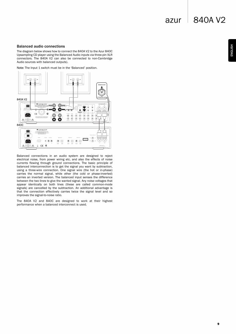
Balanced audio connectionsThe diagram below shows how to connect the 840A V2 to the Azur 840CUpsampling CD player using the Balanced Audio inputs via three-pin XLRconnectors. The 840A V2 can also be connected to non-CambridgeAudio sources with balanced outputs).
Note: The Input 1 switch must be in the ‘Balanced’ position.
Balanced connections in an audio system are designed to rejectelectrical noise, from power wiring etc, and also the effects of noisecurrents flowing through ground connections. The basic principle ofbalanced interconnection is to get the signal you want by subtraction,using a three-wire connection. One signal wire (the hot or in-phase)carries the normal signal, while other (the cold or phase-inverted)carries an inverted version. The balanced input senses the differencebetween the two lines to give the wanted signal. Any noise voltages thatappear identically on both lines (these are called common-modesignals) are cancelled by the subtraction. An additional advantage isthat the connection effectively carries twice the signal level and soimproves the signal-to-noise ratio.
The 840A V2 and 840C are designed to work at their highestperformance when a balanced interconnect is used.
9
840A V2azur
ENG
LIS
H
840C
840A V2

10
Operating instructions
The 840A V2 has a custom-made display on the front of the unit showingthe current status and allowing you to access the 840A V2 SystemConfigure menus. Here you can adjust the listening settings of theamplifier to personal preference. The menu system is easy to navigateand control, simply by using the input select buttons to turn a feature on(solid circle) or off (no circle) and the volume control knob toincrease/decrease settings.
Volume
Adjust the volume control knob on the front panel (or using the remotecontrol). The display will show the change in volume in decibels (dB).‘OdB’ indicates maximum volume while lower volume settings progressinto the negative range. This can also be changed to volume units (0-96)in the System Configure menu.
Speaker A/B
Press the Speaker A/B button to scroll through the speaker setsconnected via the rear panel: speakers A, B or A and B.
Balance
Press the Mode button to enter Balance mode. BALANCE will appear onthe display and can be adjusted using the volume control. Press theMode button again to return to Volume mode or wait 5 seconds for the840A V2 to automatically exit Balance mode.
Bass and TrebleThese controls allow subtle adjustments to the tonal balance of thesound. Modify the sound through your loudspeakers and the Pre-Outsockets only; they do not affect the signals sent through the Tape Outconnections. With a well produced CD and a good system the tonecontrols are unnecessary and can be switched out by pressing theDirect button:
This completely removes them from the signal path for maximumfidelity. If the musical recording is of poor quality or other factors areaffecting the sound quality, if desired you can adjust the tone controls tocompensate. To use the tone controls press the Direct button so that theBass/Treble icon ( ) lights in the display indicating that they areactive and direct mode is Off. Now press the Bass or Treble controlsthemselves to release them and allow adjustment; push them back inwhen finished:
The 840A V2 stores whether direct mode is on or off for each inputindividually, for example it is possible to have the tone controlsautomatically active for the Tuner source but not the CD source.
Amplifier setup
The 840A V2 features many advanced settings that allow it’s use to becustomised to user preference. The inputs can be named to reflect theactual source units you have, each input can be trimmed so that eachsounds the same in terms of loudness when you switch between themand other options.
Changing input names / source namingPress and hold the relevant input select button for four seconds to
change its name. For example, if Input 1 is a CD player, name it “CD” etc.Letters are selected by turning the volume control to scroll through theavailable characters. Press LEFT or RIGHT to select which character youwish to edit. Press EXT CHAR to access an extended character set. PressOK to confirm and exit the input name change menu.
System Configure menu
Press and hold the Mode button to access the System Configure menu.The menu options are Clip detector, LCD brightness, Speaker shortdetector, Input gain trim, Volume ramp, Volume display, Front IR andFixed input gain.
To exit the System Configure menu and its sub-menus, press the Modebutton again.
Clip detector / Speaker short detectorRefer to the ‘CAP5’ section of this manual for more information on theClip and Short detection features of the 840A V2, as both can beenabled (default) or disabled.
LCD brightness
In the System Configure menu press the LCD input select button to scrollthrough bright/dim/off settings for the front panel display. Press theMode button to exit.
Volume ramp
The 840A V2 automatically ramps the volume down when going intoStandby mode and up when coming out of Standby mode. To turn thisfeature off, press the VOL RAMP input select button in the SystemConfigure menu and set to off. Press the Mode button to exit.
Mode
Volume
Speaker A/B
Volume
Mode
Volume
Bass Treble Direct
Mode
Volume
Mode
Volume
Mode
Volume
Mode
Volume
Bass Treble Direct

11
840A V2azur
ENG
LIS
HVolume display
To change the volume display from decibels (-95 to 0dB) to arbitraryvolume units (0 to 96 units) select VOL DB in the System Configuremenu. Press the input select button to turn off the volume in decibels.Press the Mode button to exit.
Front IR
Used in conjunction with Custom Installation (C.I.) systems or IRrepeater systems, it may be desirable to disable the front panel IR bysetting FRONT IR to off (press the input select button to turn off). Pressthe Mode button to exit.
Input gain trim
The relative levels of the inputs can be adjusted by gain trim. This allowseach to be adjusted so that each sounds the same in terms of averageloudness when you switch between them. Pick the loudest soundingsource and trim its level until it matches the average perceived level ofthe others. Repeat this process if other sources also stand out as louderthan the average.
To set the input gain trim for each source, select INP TRIM in the SystemConfigure menu. Select the input required and use the volume control toset the gain between 0 and -12 dB (the available range is restricted ifthe volume is set very low). Press the Mode button to exit.
Fixed level inputsAny input of the 840A V2 is able to be set for fixed gain. Whenever thisinput is selected the gain will automatically go to this value and will not beadjustable by the volume control. This feature allows the 840A V2 to beeffectively used as a stereo power amplifier (for that selected input only).For example, as well as operating as a pure stereo amplifier, the 840A V2can provide the amplification for the front left and right channels of asurround sound setup with an AV receiver providing amplification for theother channels and controlling the overall system volume.
When listening in stereo use the 840A V2 and connected stereo sourcesas normal for best possible sound quality. For surround sound, selectthe fixed level input you have chosen on the 840A V2 and now use theAV receiver to control the volume, select connected surround soundsources etc. You may wish to re-name the fixed level input as “A/Vmode” or similar on the 840A V2. Make connections as below, the leftand right preamp outputs of the AV receiver connect to the fixed gaininput chosen on the 840A V2. As the gain can be fixed to any value it iseasy to match the level of the 840A V2 to that of the other AV channels.
To set a fixed volume for a source, select FIXED INP in the SystemConfigure menu:
Select the input required and set the fixed gain using the volume control(the OFF setting does not disable the input but leaves the input gainsubject to the volume control which is the default setting). When asource has a fixed input, the balance is always set to neutral. Press theMode button to exit.
On/Off control menuWhen going in/out of Standby mode the 840A V2 can automatically turnon and off other connected Cambridge Audio Azur models that havecontrol bus sockets. For this feature to work the units must beconnected together (see diagram) by RCA/phono leads. The sockets arecolour-coded orange on the rear panels of compatible Azur models.Loop out from the 840A V2 Control Bus Out to the Control Bus In onanother Azur model (e.g. 840C). Continue the chain to other Azurmodels if required.
Now while the 840A V2 is on press and hold the Standby/On buttonuntil ON/OFF CTR appears on the display:
Select the connected Azur models by pressing the appropriate inputselect button. For example, CA XXXC for an Azur CD player (540C V2,640C V2), CA XXXD for an Azur DVD player, CA DAB T for an Azur DABtuner etc.
Press ON & OFF to scroll through the options of ON (turns all Azur unitson only), OFF (turns all Azur units into Standby only) or ON & OFF (turnsall Azur units on and into Standby mode).
Press OK to confirm and exit.
840A V2
AV receiver
L R
SL SR
C
SB
SW
L R
Surroundsound
sources
Stereosources
Mode
Volume
Volume
Standby / On
AerialInput
50 OhmsF-Type
AerialInput
50 OhmsF-Type
Line Output
Line Output
Right
Right
Left
Left
IR Emitter
In InOut
Control Bus
ToslinkOptical
Digital OutputsOn OffPower
Manufactured in an ISO9002 approved facility
S/P DIFCo-axial
CautionRisk of electric shock.
Do not open.
AvisRisque de choc electrique.
Ne pas ouvrir.
AchtungVorm öffnen des gerätes.
Netzstecker ziehen.
Power Rating: 230V AC ~ 50Hz
www.cambridge-audio.com
Designed in London, England
azur 640T DAB/FM Tuner V2.0
Max Power Consumption: 15W
N1863
840C
840A V2
640T V2.0
Mode
Volume
Mode
Volume
Mode
Volume

12
The 840A V2 features Incognito Ready/A-BUS Ready outputs, allowing multi-roomcapability. One or two amplified keypadscan be plugged into the 840A V2 (usingCat5/5e cable and RJ45 plugs) to providemulti-room audio in one or two secondaryrooms or zones. The keypads are powered by an external PSU (alsorequired) through the Cat5/5e cables and no mains connection isrequired in the secondary rooms.
The 840A V2 is Incognito Ready Type II, which means the keypads canoperate independently of the amplifier in terms of volume/bass/trebleetc, be independently turned on and off, and can also listen to adifferent source from that which is currently selected on the amplifier.However, both keypads can only listen to the same source.
A-BUS is a standard that allows compatibility between differentmanufacturers equipment, so A-BUS compatible keypads from othermanufacturers can also be used. If used with our own Incognito KP10keypads, there are some extra features such as the ability to changesource on the 840A V2 from the keypad (EU model shown here):
Connections to the 840A V2’s Incognito Ready / A-BUS Ready outputsare made by Cat-5 cable (terminated with an RJ45 jack plug). The RJ45plug must be wired to the EIA/TIA 568A wiring standard:
To allow control of your source equipment from the remote rooms an IRemitter (IR10) is plugged into one of the IR outputs on the rear of theunit and then attached over the IR window of the source unit.Alternatively, on our own products that feature IR emitter Inputs, a mini-jack to mini-jack lead can be used. Commands received by the keypadscan now be sent back to the source equipment via the 840A V2.
It is then possible to control the source equipment from the remoterooms by using the source equipment's own remote controls or througha learning remote. The Incognito LR10 Learning Remote can fully controlthe keypads, “learn” the source's remote control codes (including thosefrom other manufacturers) and change source input on the 840A V2 etc.
On the front panel display of the 840A V2 the extra multi-room zones areindicated by a circle outline next to the input source (see Fig. 1). Whenlistening to the same source, the circle outline and solid circle overlap(see Fig. 2).
Fig. 1 - One or both keypads are listening to a different source (Input 2)to the amplifier (Input 1).
Fig. 2 - One or both keypads are listening to the same source (Input 2)as the amplifier (Input 2).
For further details on the Incognito multi-room system please contactyour local Cambridge Audio dealer or visit: www.cambridge-audio.com
Multi-room connections
Order of selection:
1. Input 1
2. Input 2
3. Input 3
4. Input 4
5. Input 5
6. Input 6 (Tape)
6 5 4 3 2 178
Plug view fromcontact end
3 4 5 6 7 821
View intosocket
Gather pairs, trimand insert into
RJ45 plug
Crimp wiressecurely in place
Wire colours:1. Green/White2. Green
3. Orange/White4. Blue5. Blue/White
6. Orange7. Brown/White8. Brown
Standby / On StopPlay
PauseOpenCloseSelectMenu
SkipScan
azur 840CUpsampling Compact Disc Player
PROGRAM
PS5
LR10
Cat5/5e (up to 30m / 100ft)
IR10
Mini-jack lead
Speakers (e.g. SS10)connected viaspeaker cable
KP10-EU keypad
840C
840A V2
AS10Active
Speaker
AS10PassiveSpeaker
Mode
Volume
Mode
Volume

13
840A V2azur
The 840A V2 features a Control Bus input/outputthat allow un-modulated remote controlcommands (positive logic, TTL level) to be receivedelectrically by the unit and looped to another unitif desired. These control commands are typicallygenerated by custom installation (multi-room) systems or remote IRreceiver systems. The Control Bus sockets are colour-coded orange.
An IR Emitter Input is also provided that allows modulated IR remotecontrol commands to be received electrically by the unit. Commands onthis input operate the unit only and are not looped out demodulated onthe Control Bus Output.
An RS232C port is also featured which allows the 840A V2 tobe controlled by C.I. systems.
In addition the units feature ‘direct’ IR/Control codes as well as togglecodes for some of their features to simplify programming custominstallation systems. Special direct On/Off and Mute commands can beaccessed on the supplied remote control for teaching into C.I. systemsas follows:
1. Press and hold the Standby/On button. The remote first generates it'sstandby (toggle) command. Keep the button held down, after 12seconds an amplifier “On” command will be generated. If the buttonis kept held down for a further 12 seconds, an amplifier player “Off”command is generated.
2. Press and hold the Mute button. The remote first generates it's mute(toggle) command. Keep the button held down, after 12 seconds a“Mute on” command will be generated. If the button is kept helddown for a further 12 seconds, a “Mute off” command is generated.
A full code table and RS232 protocol for this product is available on theCambridge Audio website: www.cambridge-audio.com
Custom installation (C.I.) use
IR EmitterIn In Out
Control Bus
ENG
LIS
H

14
CAP5 - Fiveway protection system
Cambridge Audio has developed a proprietary protection system toensure reliability and a long life for its amplifiers and the speakers theyare connected to. Note: Due to the required sensitivity of the CAP5system, it is possible that mains power disturbances can falsely triggerCAP5 in extreme situations. This protection system comprises of fivemain protection methods:
1. DC detectionIndication - Unit has switched off during operation, display flashes “DCERROR”. Press the INFO input select button for a brief on-screendescription and remedy, or read below for more information.
Description - CAP5 offers loudspeaker protection if the output of theamplifier goes to a high constant voltage (DC) because of some internalfault. This is a rare fault although detecting it could just save thoseexpensive loudspeakers.
Remedy - Due to the necessary sensitivity of the DC protection circuit,extremely hard clipping of the amplifier may cause DC protection to betriggered. If this fault occurs press the RESET input select button, thenpress the Standby/On button to power up again and check operationwith a reduced volume level. If the DC fault occurs again please contactyour dealer for service.
2. Over temperature detectionIndication - Unit has switched off during operation, display flashes“OVER TEMP”. Press the INFO input select button for a brief on-screendescription and remedy, or read below for more information.
Description - Over temperature is caused by a combination of highlistening levels and low impedance speakers. CAP5 includestemperature detection which constantly monitors the heat generated bythe output transistors. If the monitored temperature reaches a high level(suitably within the limits of the output devices) the amplifier willautomatically switch into a fault mode. The unit should ideally be left for15 minutes in this state to cool down adequately. If the unit has not fullycooled down then the temperature may reach the limit soon after theamplifier is powered up. If the loudspeaker impedance is low thetemperature of the amplifier may rise faster as the amplifier is workingharder. If the amplifier is mounted in a cabinet or the ventilation slotsare obstructed the over temperature detection may activate/reactivateafter a short listening time.
Remedy - User related fault. The internal temperature of the outputtransistors has reached the over temperature limit. Press the RESETinput select button and leave the unit for 15 minutes to cool downbefore pressing the Standby button to resume normal operation.
3. Overvoltage/overcurrent detectionDescription - CAP5 offers V/I (voltage/current) protection by constantlymonitoring the output transistors to keep them working inside their SafeOperating Area (SOA). The SOA is a set of limits given by the outputtransistor manufacturer to ensure reliability. The V/I protection has beenincorporated within the amplifier circuitry to provide a fast response totemporary overload conditions. When the V/I protection is triggered theunit will continue to operate but distortion may be heard as the unitprotects the output transistors.
Remedy - Reduce the volume. If distortion is still present, check thespeaker connections and ratings.
4. Short circuit detectionIndication - Unit has not come out of Standby, display flashes “SPKRSHORT”. Press the INFO input select button for a brief on-screendescription and remedy, or read below for more information.
Description - During power up from Standby CAP5 performs a check onthe loudspeaker terminals to see if a short across the terminals hasbeen accidentally introduced (display flashes “SPKR CHECK”). If theresistance measured across the loudspeaker terminals is too low theunit will stay in Standby mode until the fault has been removed andPower up is re-attempted (display flashes “SPKR SHORT”).
Remedy - User related fault. There may be a short circuit between theloudspeaker terminals. Press the RESET input select button and checkall loudspeaker connections before attempting to switch the unit out ofStandby (display will flash “SPKR CHECK” then “SPKR OK” when shortcircuit fixed).
It is possible to disable the short circuit detection feature by pressing theSHORT DT button to off when in the 840A V2 System Configure menu,but it is not recommended. This would only be required if theloudspeakers have very low DC resistance.
5. Intelligent clipping detectionIndication - Volume is reduced automatically, “CLIPPING” appears onthe front panel display.
Description - CAP5 has the ability to detect when the amplifier starts toclip or overdrive at its output, which can damage loudspeakers, anddegrade the sound. Clipping distortionis caused at high volume levels whenthe output signal attempts to gooutside the maximum voltage that theamplifier can provide, causing the topsof the signal to flatten off. When CAP5detects clipping the volume will beautomatically reduced down until CAP5detects an undistorted output.
It is possible to disable the clipping detection feature by pressing theCLIP DT button to off when in the 840A V2 System Configure menu.
Note: Disabling the clipping detection is not advised as this feature hasbeen added deliberately to protect the amplifier and loudspeakers.
Clipping
Mode
Volume
Mode
Volume
Mode
Volume
Mode
Volume

15
840A V2azur
Power Output 120W RMS into 8 Ohms200W RMS into 4 Ohms
THD (unweighted) < 0.001% 1 kHz at 80% of rated power
< 0.01% 20 Hz - 20 kHz at 80% of rated power
Frequency Response 10 Hz - 50 kHz +/- 1 dB
S/N ratio (ref 1W/8 Ohm) > 93 dB
Input impedances Input 1 (balanced) 20 kOhmInputs 2-7 20 kOhmTape Input 20 kOhm
Power Amp damping factor > 110 at 1 kHz
Max power consumption 800W
Minimum power consumption Active (no signal) 70WStandby 7W
Bass & Treble controls Shelving typeMax bass boost/cut +/- 10 dB at 10 HzMax treble boost/cut +/- 7.5 dB at 20 kHz
Dimensions (H x W x D) 115 x 430 x 385mm (4.5 x 16.9 x 15.2”)
Weight 15.0kg (33Lbs)
Technical specifications
There is no powerEnsure the AC power cord is connected securely.
Ensure the plug is fully inserted into the wall socket and is switched on.
Check fuse in the mains plug or adaptor.
There is no soundMake sure the unit is not in Standby mode.
Check that source component is properly connected.
Check that TAPE MON is not switched on (unless tape input is required).
Check that your speakers are properly connected.
If using Speaker B terminals check they are switched on.
Make sure unit is not in mute mode.
There is no sound on one channelEnsure that balance control is in the correct position.
Check speaker connections.
Check interconnects.
There is a loud buzz or humCheck turntable or tone arm for ground and connection lead fault.
Ensure no interconnects are loose or defective.
Ensure that your tape deck/turntable is not too close to the amplifier.
Unable to make or play tape recordingsCheck that TAPE MON and TAPE OUT have been connected correctly.
There is weak bass or diffused stereo imaging Ensure that speakers are not wired out of phase.
Message on display flashingSee section on CAP5 protection system.
The remote handset will not function Check that the batteries have not expired.
Ensure that nothing is blocking the remote sensor.
For more frequently asked questions (FAQ’s), technical advice andinformation on getting the most out of your 840A V2, please visit theSupport section on Cambridge Audio’s website:
www.cambridgeaudio.com/support.php
Troubleshooting
Visit www.cambridge-audio.com and register to receive notification of futurehardware and software releases.
This guide is designed to make installing and using this product as easy aspossible. Information in this document has been carefully checked for accuracy atthe time of printing; however, Cambridge Audio's policy is one of continuousimprovement, therefore design and specifications are subject to change withoutprior notice. If you notice any errors please feel free to email us at:[email protected]
This document contains proprietary information protected by copyright. All rightsare reserved. No part of this manual may be reproduced by any mechanical,electronic or other means, in any form, without prior written permission of themanufacturer. All trademarks and registered trademarks are the property of theirrespective owners.
Incognito and Incognito Ready are trademarks of Cambridge Audio Ltd. All rightsreserved.
Class XD Technology International Patent Pending Cambridge Audio Ltd.
© Copyright Cambridge Audio Ltd 2007
A-BUS and A-BUS Ready are registered trademarks of LeisureTech Electronics PtyLtd Australia. This product may be covered by one of more of the following patentsUS 7,181,023, 6,389,139, EP 1004222, AU 739808, NZ 502982, MexicoZ41196, Canada CA2301062.
iPod is a registered trademark of Apple Computer, Inc. All rights reserved.
ENG
LIS
H

AP21
393/
1
Cambridge Audio
Gallery Court
Hankey Place
London SE1 4BB
England
www.cambridge-audio.com
© 2007 Cambridge Audio Ltd