2012 SunSpec Alliance Members Meeting John Nunneley, Executive Director.

AXS Port SunSpec Modbus Interface
Owner’s Manual

About OutBack Power Technologies OutBack Power Technologies is a leader in advanced energy conversion technology. OutBack products include true sine wave inverter/chargers, maximum power point tracking charge controllers, and system communication components, as well as circuit breakers, batteries, accessories, and assembled systems.
Grid/Hybrid™ As a leader in off-grid energy systems designed around energy storage, OutBack Power is an innovator in Grid/Hybrid system technology, providing the best of both worlds: grid-tied system savings during normal or daylight operation, and off-grid independence during peak energy times or in the event of a power outage or an emergency. Grid/Hybrid systems have the intelligence, agility and interoperability to operate in multiple energy modes quickly, efficiently, and seamlessly, in order to deliver clean, continuous and reliable power to residential and commercial users while maintaining grid stability.
Contact Information Address: Corporate Headquarters
17825 – 59th Avenue N.E. Suite B Arlington, WA 98223 USA
European Office Hansastrasse 8 D-91126 Schwabach, Germany
Telephone:
+1.360.435.6030 +1.360.618.4363 (Technical Support) +1.360.435.6019 (Fax)
+49.9122.79889.0 +49.9122.79889.21 (Fax)
Email: [email protected]
Website: http://www.outbackpower.com
Disclaimer UNLESS SPECIFICALLY AGREED TO IN WRITING, OUTBACK POWER TECHNOLOGIES:
(a) MAKES NO WARRANTY AS TO THE ACCURACY, SUFFICIENCY OR SUITABILITY OF ANY TECHNICAL OR OTHER INFORMATION PROVIDED IN ITS MANUALS OR OTHER DOCUMENTATION.
(b) ASSUMES NO RESPONSIBILITY OR LIABILITY FOR LOSS OR DAMAGE, WHETHER DIRECT, INDIRECT, CONSEQUENTIAL OR INCIDENTAL, WHICH MIGHT ARISE OUT OF THE USE OF SUCH INFORMATION. THE USE OF ANY SUCH INFORMATION WILL BE ENTIRELY AT THE USER’S RISK.
OutBack Power Technologies cannot be responsible for system failure, damages, or injury resulting from improper installation of their products.
Notice of Copyright AXS Port Owner’s Manual © 2012 by OutBack Power Technologies. All Rights Reserved.
Trademarks OutBack Power is a registered trademark of OutBack Power Technologies.
Date and Revision April 2016, Revision C
Part Number 900-0138-01-00 Rev C
900-0138-01-00 Rev C 3
Table of Contents Introduction ................................................................................................. 5
Welcome to OutBack Power Systems ........................................................................................................................... 5 Audience ................................................................................................................................................................................. 5 AXS Port Features ................................................................................................................................................................. 5
Dimensions ........................................................................................................................................................................................ 6 Accessories ......................................................................................................................................................................................... 6
Operation .................................................................................................... 7
Installation Instructions...................................................................................................................................................... 7 Mounting ............................................................................................................................................................................................ 7 Networking ........................................................................................................................................................................................ 8
LED Indicators ........................................................................................................................................................................ 9 Reset Switch ........................................................................................................................................................................... 9
Security Protection ........................................................................................................................................................................ 10 SunSpec Blocks .................................................................................................................................................................. 10
Columns ............................................................................................................................................................................................ 10 SunSpec Block Structure.............................................................................................................................................................. 10 Device-Specific Blocks .................................................................................................................................................................. 11
SD Card Logging ................................................................................................................................................................ 15 Datalogging with OPTICS RE ...................................................................................................................................................... 15 Data Log File Format ..................................................................................................................................................................... 15
FTP Access to Logs ............................................................................................................................................................ 16 Firmware Updates ............................................................................................................................................................. 16 Email Functions .................................................................................................................................................................. 17
Troubleshooting ......................................................................................... 19
Basic Troubleshooting ..................................................................................................................................................... 19 Error Codes ....................................................................................................................................................................................... 19
Specifications ............................................................................................. 21
Regulatory Specifications ............................................................................................................................................... 21 Device Specifications ....................................................................................................................................................... 21 Factory Default Settings ................................................................................................................................................. 21
List of Tables Table 1 OutBack Block .................................................................................................................................. 11 Table 2 Charge Controller Block ............................................................................................................... 12 Table 3 Charge Controller Configuration Block .................................................................................. 13 Table 4 Email Setup ....................................................................................................................................... 17 Table 5 Basic Troubleshooting .................................................................................................................. 19 Table 6 Error Codes ........................................................................................................................................ 19 Table 7 Regulatory Specifications ............................................................................................................ 21 Table 8 Device Specifications .................................................................................................................... 21
Table of Contents
4 900-0138-01-00 Rev C
List of Figures Figure 1 Features ................................................................................................................................................ 5 Figure 2 Dimensions .......................................................................................................................................... 6 Figure 3 Wall Mount .......................................................................................................................................... 7 Figure 4 DIN Rail Mount ................................................................................................................................... 7 Figure 5 Networking .......................................................................................................................................... 8 Figure 6 Accessories .......................................................................................................................................... 9 Figure 7 LED Indicators ..................................................................................................................................... 9 Figure 8 Reset Switch ........................................................................................................................................ 9 Figure 9 Data Log Example for the FX (E series) Inverter ................................................................... 15 Figure 10 Data Log Example for the Charge Controller ....................................................................... 15 Figure 11 Firmware Update ............................................................................................................................. 16

900-0138-01-00 Rev C 5
Introduction Welcome to OutBack Power Systems Thank you for purchasing the OutBack AXS Port. This product provides communication with other OutBack devices. The device uses Ethernet access implemented by the Modbus Transmission Control Protocol. The SunSpec protocol enables sending and receiving of remote commands, control settings, and status information.
The AXS Port is enabled for OPTICS RE. OPTICS RE is the web-based remote monitoring and control application for OutBack devices.
NOTE: This product is for use in place of a system display such as the MATE3. OutBack does not support the use of the AXS Port and a system display at the same time.
Audience This manual is intended for use by anyone required to install and operate this equipment. Operators must have software engineering knowledge and must be conversant in ANSI C programming and the Modbus protocol. SunSpec client software is required for operation.
AXS Port Features
Figure 1 Features
HUB/Device Port
Network Port
Temp Sensor
Port
Mounting Tab
DIN Rail Mount
MicroSD Card Slot
OutBack Device Communications
LED
Modbus Activity
LED
Power LED
Ethernet Activity
LED
SD Card LED
Fault LED
Reset Switch
Ethernet Link LED
Introduction
6 900-0138-01-00 Rev C
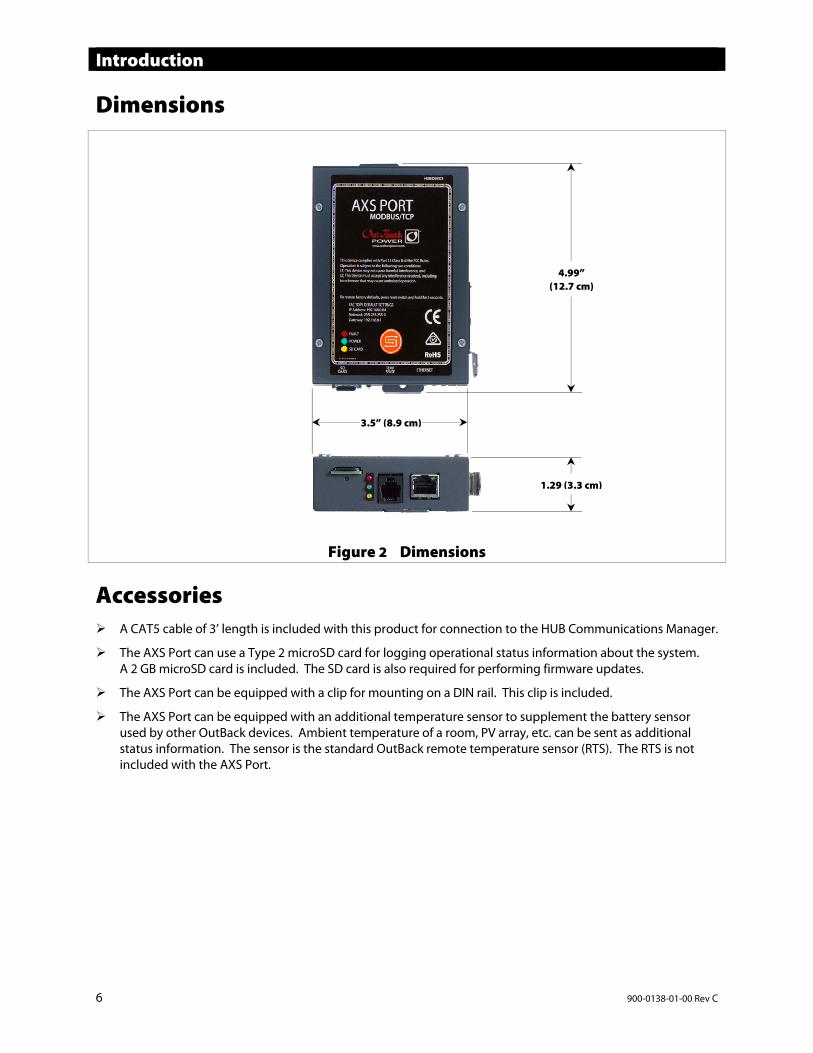
Dimensions
Figure 2 Dimensions
Accessories A CAT5 cable of 3’ length is included with this product for connection to the HUB Communications Manager.
The AXS Port can use a Type 2 microSD card for logging operational status information about the system. A 2 GB microSD card is included. The SD card is also required for performing firmware updates.
The AXS Port can be equipped with a clip for mounting on a DIN rail. This clip is included.
The AXS Port can be equipped with an additional temperature sensor to supplement the battery sensor used by other OutBack devices. Ambient temperature of a room, PV array, etc. can be sent as additional status information. The sensor is the standard OutBack remote temperature sensor (RTS). The RTS is not included with the AXS Port.
4.99” (12.7 cm)
3.5” (8.9 cm)
1.29 (3.3 cm)
900-0138-01-00 Rev C 7
Operation Installation Instructions
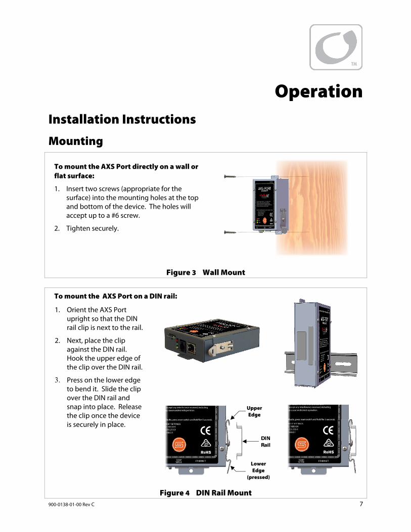
Mounting
Figure 3 Wall Mount
Figure 4 DIN Rail Mount
To mount the AXS Port directly on a wall or flat surface:
1. Insert two screws (appropriate for the surface) into the mounting holes at the top and bottom of the device. The holes will accept up to a #6 screw.
2. Tighten securely.
To mount the AXS Port on a DIN rail:
1. Orient the AXS Port upright so that the DIN rail clip is next to the rail.
2. Next, place the clip against the DIN rail. Hook the upper edge of the clip over the DIN rail.
3. Press on the lower edge to bend it. Slide the clip over the DIN rail and snap into place. Release the clip once the device is securely in place.
Upper Edge
DIN Rail
Lower Edge
(pressed)
Operation
8 900-0138-01-00 Rev C
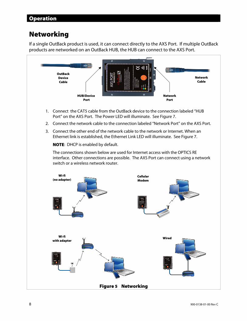
Networking If a single OutBack product is used, it can connect directly to the AXS Port. If multiple OutBack products are networked on an OutBack HUB, the HUB can connect to the AXS Port.
Figure 5 Networking
OutBack Device Cable
Network Cable
1. Connect the CAT5 cable from the OutBack device to the connection labeled “HUB Port” on the AXS Port. The Power LED will illuminate. See Figure 7.
2. Connect the network cable to the connection labeled “Network Port” on the AXS Port.
3. Connect the other end of the network cable to the network or Internet. When an Ethernet link is established, the Ethernet Link LED will illuminate. See Figure 7.
NOTE: DHCP is enabled by default.
The connections shown below are used for Internet access with the OPTICS RE interface. Other connections are possible. The AXS Port can connect using a network switch or a wireless network router.
HUB/Device Port
Network Port
Wi-fi (no adapter)
Cellular Modem
Wi-fi with adapter
Wired
Operation
900-0138-01-00 Rev C 9
Figure 6 Accessories
LED Indicators
Figure 7 LED Indicators
Reset Switch
Figure 8 Reset Switch
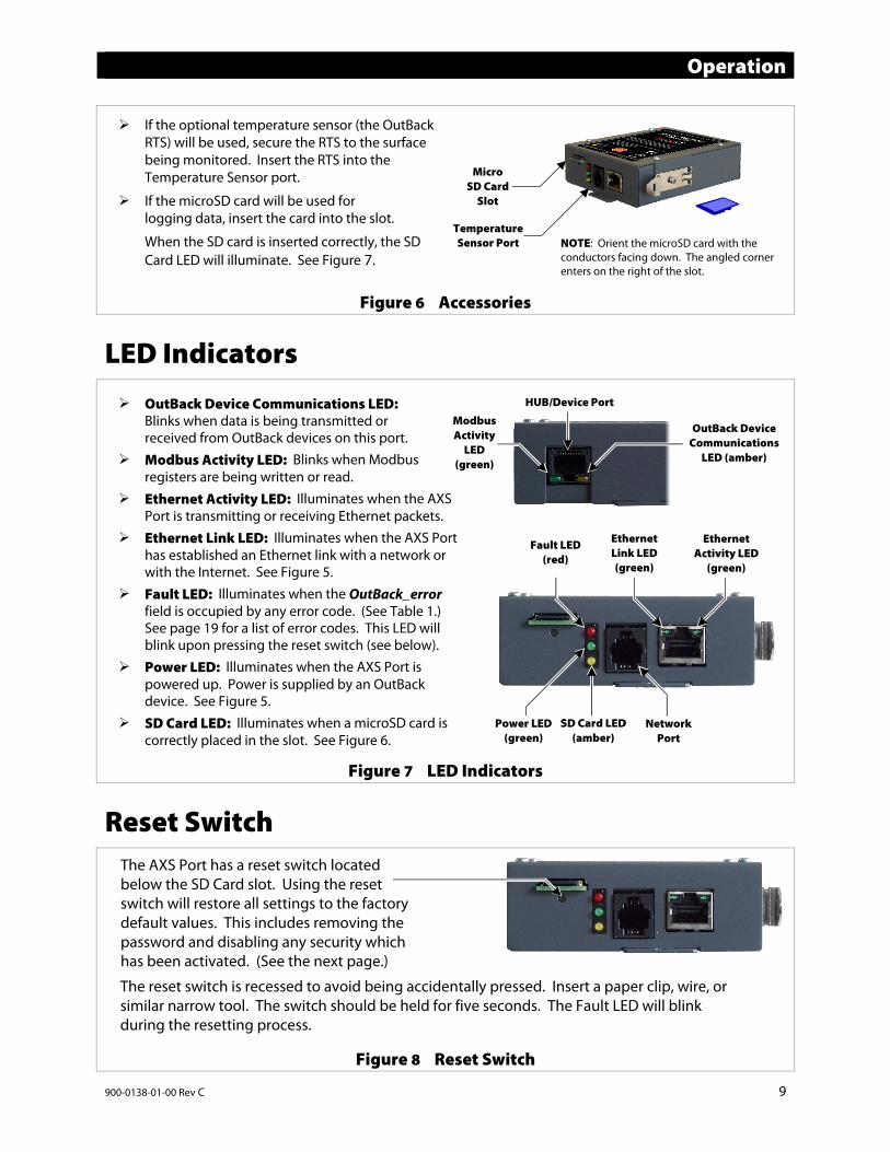
If the optional temperature sensor (the OutBackRTS) will be used, secure the RTS to the surface being monitored. Insert the RTS into the Temperature Sensor port.
If the microSD card will be used for logging data, insert the card into the slot.
When the SD card is inserted correctly, the SD Card LED will illuminate. See Figure 7.
Micro SD Card
Slot
Temperature Sensor Port NOTE: Orient the microSD card with the
conductors facing down. The angled corner enters on the right of the slot.
OutBack Device Communications LED: Blinks when data is being transmitted or received from OutBack devices on this port.
Modbus Activity LED: Blinks when Modbus registers are being written or read.
Ethernet Activity LED: Illuminates when the AXS Port is transmitting or receiving Ethernet packets.
Ethernet Link LED: Illuminates when the AXS Port has established an Ethernet link with a network or with the Internet. See Figure 5.
Fault LED: Illuminates when the OutBack_error field is occupied by any error code. (See Table 1.) See page 19 for a list of error codes. This LED will blink upon pressing the reset switch (see below).
Power LED: Illuminates when the AXS Port is powered up. Power is supplied by an OutBack device. See Figure 5.
SD Card LED: Illuminates when a microSD card is correctly placed in the slot. See Figure 6.
Modbus Activity
LED (green)
HUB/Device Port
Fault LED (red)
Ethernet Activity LED
(green)
Ethernet Link LED (green)
SD Card LED (amber)
Power LED (green)
Network Port
The AXS Port has a reset switch located below the SD Card slot. Using the reset switch will restore all settings to the factory default values. This includes removing the password and disabling any security which has been activated. (See the next page.)
The reset switch is recessed to avoid being accidentally pressed. Insert a paper clip, wire, or similar narrow tool. The switch should be held for five seconds. The Fault LED will blink during the resetting process.
OutBack Device Communications
LED (amber)
Operation
10 900-0138-01-00 Rev C
Security Protection To enhance security, the AXS Port has been designed to enable a basic form of encryption. To enable it, the user must contact OutBack Power Technologies. A non-disclosure agreement must be signed.
Resetting the AXS Port with the reset switch will restore all values to the factory default settings. This includes removing the password and disabling the security features.
Using the AXS Port with the security features disabled is not recommended when communicating over the Internet. Since the initial password state is unsecured, it is recommended that the password is set over a secure local area network before connecting to the Internet.
SunSpec Blocks The AXS Port uses the SunSpec protocol to assemble blocks of data on each connected product. The SunSpec client software can read or write to each field in a data block on the AXS Port. The fields are used for remote commands, control settings, or status information on the OutBack product.
A user with SunSpec client software can use the following tables to interpret these data blocks. Samples of the SunSpec client software are available on the OutBack website’s AXS Port page at www.outbackpower.com/outback-products/communications/item/axs-port?category_id=440. For more information on the SunSpec protocol, go to www.sunspec.org.
Columns DID: A unique identifier for a device type within the system.
Start and End: The register addresses for the beginning and end of each field, offset from the beginning of the block.
Size: The number of registers occupied by each field.
R/W: Indicates this field’s permissions.
Field name: The name and function of each field.
Type: Explains how the field’s data is formatted.
Units: The units of measure for each field, if applicable.
Scale Factor: Indicates scaling a measurement value.
Contents: Classification of field data (or a fixed value, where applicable).
Description: Describes the field data.
SunSpec Block Structure The first block is the Common Block, which supplies vendor and model information for the device.
The second (and subsequent) blocks will be device-specific, such as a block for charge controllers. NOTE: OutBack charge controllers have a separate block for status fields and a separate block for command and control fields. See page 12.
The final End Block formally marks the end of the block structure.
Operation
900-0138-01-00 Rev C 11
Device-Specific Blocks The following blocks show an example of devices supported by OutBack Power.
NOTE: The blocks depicted here may be subject to change without notice and should be used as examples only. For current blocks, go to the AXS Port page on www.outbackpower.com. An application note is available displaying all device blocks.
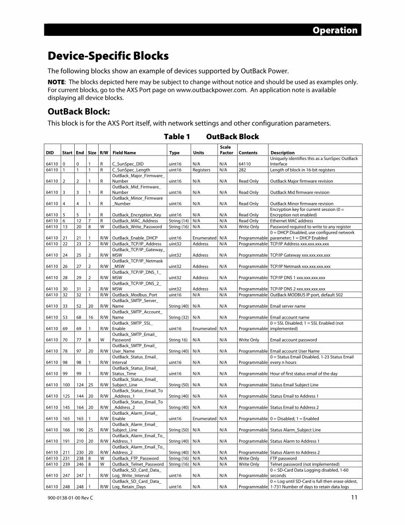
OutBack Block: This block is for the AXS Port itself, with network settings and other configuration parameters.
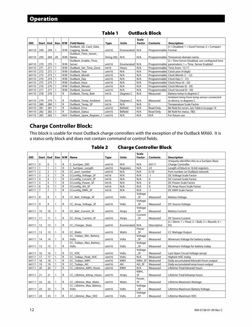
Table 1 OutBack Block
DID Start End Size R/W Field Name Type UnitsScale Factor Contents Description
64110 0 0 1 R C_SunSpec_DID uint16 N/A N/A 64110 Uniquely identifies this as a SunSpec OutBack Interface
64110 1 1 1 R C_SunSpec_Length uint16 Registers N/A 282 Length of block in 16-bit registers
64110 2 2 1 R OutBack_Major_Firmware_Number uint16 N/A N/A Read Only OutBack Major firmware revision
64110 3 3 1 R OutBack_Mid_Firmware_ Number uint16 N/A N/A Read Only OutBack Mid firmware revision
64110 4 4 1 R OutBack_Minor_Firmware_Number uint16 N/A N/A Read Only OutBack Minor firmware revision
64110 5 5 1 R OutBack_Encryption_Key uint16 N/A N/A Read OnlyEncryption key for current session (0 = Encryption not enabled)
64110 6 12 7 R OutBack_MAC_Address String (14) N/A N/A Read Only Ethernet MAC address 64110 13 20 8 W OutBack_Write_Password String (16) N/A N/A Write Only Password required to write to any register
64110 21 21 1 R/W OutBack_Enable_DHCP uint16 Enumerated N/A Programmable0 = DHCP Disabled, use configured network parameter; 1 = DHCP Enabled
64110 22 23 2 R/W OutBack_TCP/IP_Address uint32 Address N/A Programmable TCP/IP Address xxx.xxx.xxx.xxx
64110 24 25 2 R/W OutBack_TCP/IP_Gateway_MSW uint32 Address N/A Programmable TCP/IP Gateway xxx.xxx.xxx.xxx
64110 26 27 2 R/W OutBack_TCP/IP_Netmask_MSW uint32 Address N/A Programmable TCP/IP Netmask xxx.xxx.xxx.xxx
64110 28 29 2 R/W OutBack_TCP/IP_DNS_1_ MSW uint32 Address N/A Programmable TCP/IP DNS 1 xxx.xxx.xxx.xxx
64110 30 31 2 R/W OutBack_TCP/IP_DNS_2_ MSW uint32 Address N/A Programmable TCP/IP DNS 2 xxx.xxx.xxx.xxx
64110 32 32 1 R/W OutBack_Modbus_Port uint16 N/A N/A Programmable OutBack MODBUS IP port, default 502
64110 33 52 20 R/W OutBack_SMTP_Server_ Name String (40) N/A N/A Programmable Email server name
64110 53 68 16 R/W OutBack_SMTP_Account_Name String (32) N/A N/A Programmable Email account name
64110 69 69 1 R/W OutBack_SMTP_SSL_ Enable uint16 Enumerated N/A Programmable
0 = SSL Disabled; 1 = SSL Enabled (not implemented)
64110 70 77 8 W OutBack_SMTP_Email_ Password String 16) N/A N/A Write Only Email account password
64110 78 97 20 R/W OutBack_SMTP_Email_ User_Name String (40) N/A N/A Programmable Email account User Name
64110 98 98 1 R/W OutBack_Status_Email_ Interval uint16 N/A N/A Programmable
0 = Status Email Disabled, 1-23 Status Email every n hours
64110 99 99 1 R/W OutBack_Status_Email_ Status_Time uint16 N/A N/A Programmable Hour of first status email of the day
64110 100 124 25 R/W OutBack_Status_Email_ Subject_Line String (50) N/A N/A Programmable Status Email Subject Line
64110 125 144 20 R/W OutBack_Status_Email_To_Address_1 String (40) N/A N/A Programmable Status Email to Address 1
64110 145 164 20 R/W OutBack_Status_Email_To_Address_2 String (40) N/A N/A Programmable Status Email to Address 2
64110 165 165 1 R/W OutBack_Alarm_Email_ Enable uint16 Enumerated N/A Programmable 0 = Disabled; 1 = Enabled
64110 166 190 25 R/W OutBack_Alarm_Email_ Subject_Line String (50) N/A N/A Programmable Status Alarm_Subject Line
64110 191 210 20 R/W OutBack_Alarm_Email_To_Address_1 String (40) N/A N/A Programmable Status Alarm to Address 1
64110 211 230 20 R/W OutBack_Alarm_Email_To_Address_2 String (40) N/A N/A Programmable Status Alarm to Address 2
64110 231 238 8 W OutBack_FTP_Password String (16) N/A N/A Write Only FTP password 64110 239 246 8 W OutBack_Telnet_Password String (16) N/A N/A Write Only Telnet password (not implemented)
64110 247 247 1 R/W OutBack_SD_Card_Data_ Log_Write_Interval uint16 N/A N/A Programmable
0 = SD-Card Data Logging disabled, 1-60 seconds
64110 248 248 1 R/W OutBack_SD_Card_Data_ Log_Retain_Days uint16 N/A N/A Programmable
0 = Log until SD-Card is full then erase oldest, 1-731 Number of days to retain data logs
Operation
12 900-0138-01-00 Rev C
Table 1 OutBack Block
DID Start End Size R/W Field Name Type UnitsScale Factor Contents Description
64110 249 249 1 R/W OutBack_SD_Card_Data_ Logging_Mode uint16 Enumerated N/A Programmable
0 = Disabled; 1 = Excel Format; 2 = Compact Format
64110 250 269 20 R/W OutBack_Time_Server_ Name String (40) N/A N/A Programmable Timeserver domain name
64110 270 270 1 R/W OutBack_Enable_Time_ Server uint16 Enumerated N/A Programmable
0 = Time Server Disabled, use configured time parameters; 1 = Time Server Enabled
64110 271 271 1 R/W OutBack_Set_Time_Zone int16 Hours N/A Programmable Time Zone -12-11 64110 272 272 1 R/W OutBack_Year uint16 N/A N/A Programmable Clock year (4 digit) 64110 273 273 1 R/W OutBack_Month uint16 N/A N/A Programmable Clock Month (1 - 12) 64110 274 274 1 R/W OutBack_Day uint16 N/A N/A Programmable Clock Day (1 - 31) 64110 275 275 1 R/W OutBack_Hour uint16 N/A N/A Programmable Clock Hour (0 - 23) 64110 276 276 1 R/W OutBack_Minute uint16 N/A N/A Programmable Clock Minute (0 - 59) 64110 277 277 1 R/W OutBack_Second uint16 N/A N/A Programmable Clock Second (0 - 59) 64110 278 278 1 R OutBack_Temp_Batt int16 Degrees C N/A Measured Battery temp in degrees C
64110 279 279 1 R OutBack_Temp_Ambient int16 Degrees C N/A MeasuredAmbient temp from temp sensor connected to device, in degrees C
64110 280 280 1 R OutBack_Temp_SF int16 N/A N/A 0 Temperature Scale Factor 64110 281 281 1 R OutBack_Error uint16 Bitfield N/A Read Only Bit field for errors. See Table 6 on page 19. 64110 282 282 1 R OutBack_Status uint16 Bitfield N/A Read Only Bit field for status. TBD. 64110 283 283 1 N/A OutBack_Spare_Register_1 uint16 N/A N/A N/A For future use
Charge Controller Block: This block is usable for most OutBack charge controllers with the exception of the OutBack MX60. It is a status-only block and does not contain command or control fields.
Table 2 Charge Controller Block
DID Start End Size R/W Name Type UnitsScale Factor Contents Description
64111 0 0 1 R C_SunSpec_DID uint16 N/A N/A 64111Uniquely identifies this as a SunSpec Basic Charge Controller
64111 1 1 1 R C_SunSpec_Length uint16 Registers N/A 23 Length of block in 16-bit registers64111 2 2 1 R CC_port_number uint16 N/A N/A 0-10 Port number on OutBack network 64111 3 3 1 R CCconfig_Voltage_SF int16 N/A N/A -1 DC Voltage Scale Factor 64111 4 4 1 R CCconfig_Current_SF int16 N/A N/A 0 DC Current Scale Factor 64111 5 5 1 R CCconfig_Power_SF int16 N/A N/A 0 DC Power Scale Factor 64111 6 6 1 R CCconfig_AH_SF int16 N/A N/A 0 DC Amp Hours Scale Factor 64111 7 7 1 R CCconfig_KWH_SF int16 N/A N/A -1 DC kWH Scale Factor
64111 8 8 1 R CC_Batt_Voltage_SF uint16 VoltsVoltage_SF Measured Battery Voltage
64111 9 9 1 R CC_Array_Voltage_SF uint16 VoltsVoltage_SF Measured DC Source Voltage
64111 10 10 1 R CC_Batt_Current_SF uint16 AmpsVoltage_SF Measured Battery Current
64111 11 11 1 R CC_Array_Current_SF uint16 AmpsCurrent_SF Measured DC Source Current
64111 12 12 1 R CC_Charger_State uint16 Enumerated N/A Descriptive0 = Silent; 1 = Float; 2 = Bulk; 3 = Absorb; 4 = EQ
64111 13 13 1 R CC_Watts uint16 WattsPower _SF Measured CC Wattage Output
64111 14 14 1 R CC_Todays_Min_Battery_ Volts uint16 Volts
Voltage_SF Measured Minimum Voltage for battery today
64111 15 15 1 R CC_Todays_Max_Battery_ Volts uint16 Volts
Voltage_SF Measured Maximum Voltage for battery today
64111 16 16 1 R CC_VOC uint16 VoltsVoltage_SF Measured Last Open Circuit Voltage (array)
64111 17 17 1 R CC_Todays_Peak_VOC uint16 Volts N/A Measured Highest VOC today 64111 18 18 1 R CC_Todays_kWH uint16 KWH KWH_SF Measured Daily accumulated kilowatt-hours output64111 19 19 1 R CC_Todays_AH uint16 AH AH_SF Measured Daily accumulated amp-hours output 64111 20 20 1 R CC_Lifetime_kWH_Hours uint16 KWH N/A Measured Lifetime Total kilowatt hours
64111 21 21 1 R CC_Lifetime_kAmp_Hours uint16 AmpsKWH_SF Measured Lifetime Total kiloamp-hours
64111 22 22 1 R CC_Lifetime_Max_Watts uint16 WattsPower_SF Measured Lifetime Maximum Wattage
64111 23 23 1 R CC_Lifetime_Max_Battery_Volts uint16 Volts
Voltage_SF Measured Lifetime Maximum Battery Voltage
64111 24 24 1 R CC_Lifetime_Max_VOC uint16 VoltsVoltage_SF Measured Lifetime Maximum VOC

Operation
900-0138-01-00 Rev C 13
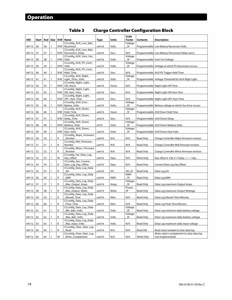
Charge Controller Configuration Block: This block always accompanies the Charge Controller Block. It is usable for most OutBack charge controllers with the exception of the OutBack MX60. It contains command and control fields for the charge controller, as well as vendor-specific status fields.
Table 3 Charge Controller Configuration Block
DID Start End Size R/W Name Type Units Scale Factor Contents Description
64112 0 0 1 R C_SunSpec_DID uint16 N/A N/A 64112 Vendor Extension for OutBack Charge Controllers
64112 1 1 1 R C_SunSpec_Length uint16 Registers N/A 64 Length of block in 16-bit registers64112 2 2 1 R CCconfig_port_number uint16 N/A N/A 0-10 Port number on OutBack network64112 3 3 1 R CCconfig_Voltage_SF int16 N/A N/A -1 DC Voltage Scale Factor 64112 4 4 1 R CCconfig_Current_SF int16 N/A N/A 0 DC Current Scale Factor 64112 5 5 1 R CCconfig_Hours_SF int16 N/A N/A -1 Time in Hours Scale Factor 64112 6 6 1 R CCconfig_Power_SF int16 N/A N/A 0 Power Scale Factor 64112 7 7 1 R CCconfig_AH_SF int16 N/A N/A 0 Amp Hours Scale Factor 64112 8 8 1 R CCconfig_KWH_SF int16 N/A N/A -1 DC kWH Scale Factor
64112 9 9 1 R CCconfig_Faults uint16 Bitfield N/A Descriptive CC Error Flags: High VOC, Over temp, Shorted Battery Temp Sensor
64112 10 10 1 R/W CCconfig_Absorb_Volts uint16 Volts Voltage_SF Programmable Absorb Voltage Target
64112 11 11 1 R/W CCconfig_Absorb_Time_ Hours uint16 Hours
Hours _SF Programmable Absorb Time Hours
64112 12 12 1 R/W CCconfig_Absorb_End_ Amps uint16 Amps
Voltage_SF Programmable Amperage to end Absorbing
64112 13 13 1 R/W CCconfig_Rebulk_Volts uint16 Volts Voltage_SF Programmable Voltage to re-initiate Bulk charge
64112 14 14 1 R/W CCconfig_Float_Volts uint16 Volts Voltage_SF Programmable Float Voltage Target
64112 15 15 1 R/W CCconfig_Bulk_Current uint16 Amps Voltage_SF Programmable Max Output Current Limit
64112 16 16 1 R/W CCconfig_EQ_Volts uint16 Volts Voltage_SF Programmable Target Voltage for Equalize
64112 17 17 1 R/W CCconfig_EQ_Time_Hours uint16 Hours N/A Programmable EQ Time Hours 64112 18 18 1 R/W CCconfig_Auto_EQ_Days uint16 Days N/A Programmable Auto EQ Interval Days
64112 19 19 1 R/W CCconfig_MPPT_Mode uint16 EnumeratedDescriptive Programmable 0 = Auto; 1 = U-Pick
64112 20 20 1 R/W CCconfig_Sweep_Width uint16 EnumeratedDescriptive Programmable 0 = Full; 1 = Half
64112 21 21 1 R/W CCconfig_Sweep_Max_ Percentage uint16 Enumerated
Descriptive Programmable 0 = 80; 1 = 85; 2 = 90; 3 = 99
64112 22 22 1 R/W CCconfig_U_Pick_PWM_ Duty_Cycle uint16 Percentage
Voltage_SF Programmable Park Duty Cycle (%)
64112 23 23 1 R/W CCconfig_Grid_Tie_Mode uint16 EnumeratedDescriptive Programmable
0 = Grid Tie Mode disabled; 1 = Grid Tie Mode enabled
64112 24 24 1 R/W CCconfig_Temp_Comp_ Mode uint16 Enumerated
Descriptive Programmable 0 = Wide; 1 = User Limited
64112 25 25 1 R/W CCconfig_Temp_Comp_ Lower_Limit_Volts uint16 Volts
Voltage_SF Programmable RTS compensation lower voltage limit
64112 26 26 1 R/W CCconfig_Temp_Comp_ Upper_Limit_Volts uint16 Volts
Voltage_SF Programmable RTS compensation upper voltage limit
64112 27 27 1 R/W CCconfig_Auto_Restart_ Mode uint16 Enumerated
Descriptive Programmable
0 = Off; 1 = Restart every 90 minutes; 2 = Restart every 90 minutes if absorb charging or float charging
64112 28 28 1 R/W CCconfig_Wakeup_VOC uint16 Volts Voltage_SF Programmable Voc change which causes Wakeup occurs
64112 29 29 1 R/W CCconfig_Snooze_Mode_ Amps uint16 Amps
Voltage_SF Programmable Snooze Mode Amps
64112 30 30 1 R/W CCconfig_Wakeup_Interval uint16 Mins N/A Programmable How often to check for Wakeup condition
64112 31 31 1 R/W CCconfig_AUX_Mode uint16 EnumeratedDescriptive Programmable
0 = Float; 1 = Diversion: Relay; 2 = Diversion: Solid St; 3 = Low Batt Disconnect; 4 = Remote; 5 = Vent Fan; 6 = PV Trigger; 7 = Error Output; 8 = Night Light
64112 32 32 1 R/W CCconfig_AUX_Control uint16 EnumeratedDescriptive Programmable 0 = Off; 1 = On; 2 = Auto
64112 33 33 1 R CCconfig_AUX_State uint16 EnumeratedDescriptive Read Only 0 = Disabled; 1 = Enabled
64112 34 34 1 R/W CCconfig_AUX_Polarity uint16 EnumeratedDescriptive Programmable 0 = Low; 1 = High
64112 35 35 1 R/W CCconfig_AUX_Low_Batt_Disconnect uint16 Volts
Voltage_SF Programmable Low Battery Disconnect Voltage
Operation
14 900-0138-01-00 Rev C
Table 3 Charge Controller Configuration Block
DID Start End Size R/W Name Type Units Scale Factor Contents Description
64112 36 36 1 R/W CCconfig_AUX_Low_Batt_Reconnect uint16 Volts
Voltage_SF Programmable Low Battery Reconnect Volts
64112 37 37 1 R/W CCconfig_AUX_Low_Batt_Disconnect_Delay uint16 Secs N/A Programmable Low Battery Disconnect Delay (secs)
64112 38 38 1 R/W CCconfig_AUX_Vent_Fan_Volts uint16 Volts
Voltage_SF Programmable Vent Fan Voltage
64112 39 39 1 R/W CCconfig_AUX_PV_Limit_ Volts uint16 Volts
Voltage_SF Programmable Voltage at which PV disconnect occurs
64112 40 40 1 R/W CCconfig_AUX_PV_Limit_ Hold_Time uint16 Secs N/A Programmable AUX PV Trigger Hold Time
64112 41 41 1 R/W CCconfig_AUX_Night_ Light_Thres_Volts uint16 Volts
Voltage_SF Programmable Voltage Threshold for AUX Night Light
64112 42 42 1 R/W CCconfig_Night_Light_ ON_Hours uint16 Hours N/A Programmable Night Light ON Time
64112 43 43 1 R/W CCconfig_Night_Light_ ON_Hyst_Time uint16 Secs N/A Programmable Night Light ON Hyst Time
64112 44 44 1 R/W CCconfig_Night_Light_ OFF_Hyst_Time uint16 Secs N/A Programmable Night Light OFF Hyst Time
64112 45 45 1 R/W CCconfig_AUX_Error_ Battery_Volts uint16 Volts
Voltage_SF Programmable Battery voltage at which Aux Error occurs
64112 46 46 1 R/W CCconfig_AUX_Divert_ Hold_Time uint16 Hours
Voltage _SF Programmable AUX Diver Hold Time
64112 47 47 1 R/W CCconfig_AUX_Divert_ Delay_Time uint16 Secs N/A Programmable AUX Divert Delay
64112 48 48 1 R/W CCconfig_AUX_Divert_ Relative_Volts int16 Volts
Voltage_SF Programmable AUX Divert Relative Volts
64112 49 49 1 R/W CCconfig_AUX_Divert_ Hyst_Volts uint16 Volts
Voltage_SF Programmable AUX Divert Hyst Volts
64112 50 50 1 R CCconfig_Major_Firmware_Number uint16 N/A N/A Read Only Charge Controller Major firmware revision
64112 51 51 1 R CCconfig_Mid_Firmware_ Number uint16 N/A N/A Read Only Charge Controller Mid firmware revision
64112 52 52 1 R CCconfig_Minor_Firmware_Number uint16 N/A N/A Read Only Charge Controller Minor firmware revision
64112 53 53 1 W CCconfig_Set_Data_Log_ Day_Offset uint16 Days N/A Write Only Day offset 0-128, 0 =Today, 1 = -1 day …
64112 54 54 1 R CCconfig_Get_Current_ Data_Log_Day_Offset uint16 Days N/A Read Only Current Data Log Day Offset
64112 55 55 1 R CCconfig_Data_Log_Daily_AH uint16 AH AH_SF Read Only Data Log AH
64112 56 56 1 R CCconfig_Data_Log_Daily_kWH uint16 KWH
KWH _SF Read Only Data Log kWH
64112 57 57 1 R CCconfig_Data_Log_Daily_Max_Output_Amps uint16 Amps
Voltage_SF Read Only Data Log maximum Output Amps
64112 58 58 1 R CCconfig_Data_Log_Daily_Max_Output_Watts uint16 Watts
Power_SF Read Only Data Log maximum Output Wattage
64112 59 59 1 R CCconfig_Data_Log_Daily_Absorb_Time uint16 Mins N/A Read Only Data Log Absorb Time Minutes
64112 60 60 1 R CCconfig_Data_Log_Daily_Float_Time uint16 Mins N/A Read Only Data Log Float Time Minutes
64112 61 61 1 R CCconfig_Data_Log_Daily_Min_Batt_Volts uint16 Volts
Voltage_SF Read Only Data Log minimum daily battery voltage
64112 62 62 1 R CCconfig_Data_Log_Daily_Max_Batt_Volts uint16 Volts
Voltage _SF Read Only Data Log maximum daily battery voltage
64112 63 63 1 R CCconfig_Data_Log_Daily_Max_Input_Volts uint16 Volts N/A Read Only Data Log maximum daily input voltage
64112 64 64 1 R CCconfig_Clear_Data_Log_Read uint16 N/A N/A Read Old Read value needed to clear data log
64112 65 65 1 W CCconfig_Clear_Data_Log_Write_Complement uint16 N/A N/A Write Only
Write value's complement to clear data log (not Implemented)
Operation
900-0138-01-00 Rev C 15
SD Card Logging When enabled, the microSD card inserted in the slot will record operational status data about the system. The AXS Port will record data to the microSD card up to the limit of the card. (It has been tested with microSD cards up to 8 GB.) The interval for automatic downloading to the microSD card can be set at intervals from 1 to 60 seconds. This setting is made in the field titled Outback_SD_Card_Data_ Log_Write_Interval. The default setting is 0 (disabled).
If the card’s capacity is exceeded, the data will begin to be overwritten starting with the oldest first.
Datalogging with OPTICS RE If the AXS Port is disconnected from OPTICS RE (through loss of the internet connection), the OPTICS Replay function will be used. During the connection loss, the AXS Port will continue logging data to the SD card. Upon reconnection, the AXS Port will begin uploading the Replay file from the SD card to OPTICS RE. If the upload is successful, this will prevent gaps in OPTICS RE datalogging.
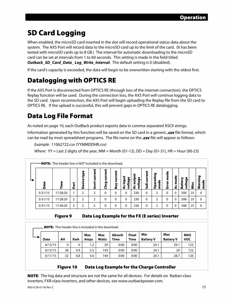
Data Log File Format As noted on page 10, each OutBack product exports data in comma-separated ASCII strings.
Information generated by this function will be saved on the SD card in a generic .csv file format, which can be read by most spreadsheet programs. The file name on the .csv file will appear as follows:
Example: 11062722.csv (YYMMDDHR.csv)
Where: YY = Last 2 digits of the year, MM = Month (01-12), DD = Day (01-31), HR = Hour (00-23)
Figure 9 Data Log Example for the FX (E series) Inverter
Figure 10 Data Log Example for the Charge Controller
NOTE: The log data and structure are not the same for all devices. For details on Radian-class inverters, FXR-class inverters, and other devices, see www.outbackpower.com.
Dat
e
Tim
e
Port
Dev
ice
type
Invr
t cur
rent
Chrg
cur
rent
Buy
cur
rent
Ac
inpu
t vo
ltag
e
Ac
outp
ut
volt
age
Sell
curr
ent
Ope
rati
ng
mod
e
Erro
r mod
e
Ac
mod
e
Bat
tery
vo
ltag
e
Mis
c
War
ning
m
ode
5/31/15 17:28:20 1 2 2 0 0 0 230 0 2 0 0 500 25 0
5/31/15 17:28:20 2 2 2 0 0 0 230 0 2 0 0 508 25 0
5/31/15 17:28:20 3 2 2 0 0 0 230 0 2 0 0 508 25 0
NOTE: This header line is NOT included in the download.
Date AH Kwh Max Amps
Max Watts
Absorb Time
Float Time
Min Battery V
Max Battery V
MAX VOC
6/13/15 0 0 1.2 29 0:00 0:00 24.1 29.1 122
6/12/15 38 0.9 5.5 143 0:00 0:00 24.1 29 122
6/11/15 32 0.8 5.6 144 0:00 0:00 24.1 28.7 120
NOTE: This header line is included in the download.
Operation
16 900-0138-01-00 Rev C
FTP Access to Logs A file transfer protocol (FTP) site such as FileZilla may be used to connect to the AXS Port. The FTP client presents a normal file explorer display of the files stored on the microSD card.
The log files are stored under the LOGFILES directory. The naming convention of the log files is the same as noted above.
NOTE: FTP access should not be used while using OPTICS RE. The AXS Card does not have enough memory to support both protocols at the same time.
Firmware Updates The firmware revision of the AXS Port can be updated directly using a microSD card, or it can be updated using an FTP site and the microSD card.
To update the firmware directly:
1. If necessary, load a firmware update to the microSD card. These updates are available at the OutBack website, www.outbackpower.com.
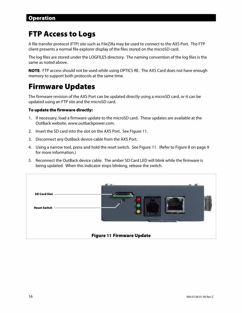
2. Insert the SD card into the slot on the AXS Port. See Figure 11.
3. Disconnect any OutBack device cable from the AXS Port.
4. Using a narrow tool, press and hold the reset switch. See Figure 11. (Refer to Figure 8 on page 9 for more information.)
5. Reconnect the OutBack device cable. The amber SD Card LED will blink while the firmware is being updated. When this indicator stops blinking, release the switch.
Figure 11 Firmware Update
Reset Switch
SD Card Slot
Operation
900-0138-01-00 Rev C 17
To update the firmware using an FTP site and the SD Card:
1. Connect to the AXS Port using the FTP site.
2. Copy the update file from the OutBack website to the UPDATEFW directory on the microSD card. NOTE: It may be necessary to create this directory on the SD card first, using the FTP client.
3. Once the update file is copied, disconnect the FTP client from the AXS Port.
4. The AXS Port will detect the disconnection of the FTP client and will automatically update the firmware if the correctly named file is found in the UPDATEFW directory. After a successful firmware update, the update file will be erased from the UPDATEFW directory.
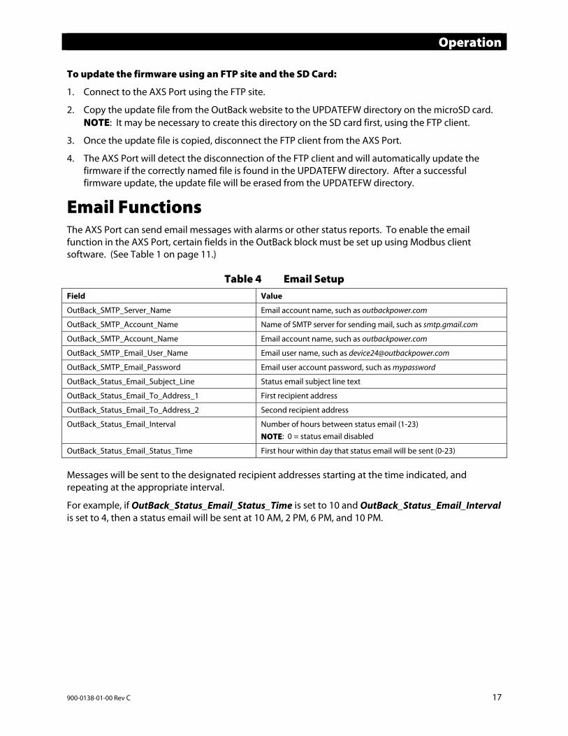
Email Functions The AXS Port can send email messages with alarms or other status reports. To enable the email function in the AXS Port, certain fields in the OutBack block must be set up using Modbus client software. (See Table 1 on page 11.)
Table 4 Email Setup
Field Value
OutBack_SMTP_Server_Name Email account name, such as outbackpower.com
OutBack_SMTP_Account_Name Name of SMTP server for sending mail, such as smtp.gmail.com
OutBack_SMTP_Account_Name Email account name, such as outbackpower.com
OutBack_SMTP_Email_User_Name Email user name, such as [email protected]
OutBack_SMTP_Email_Password Email user account password, such as mypassword
OutBack_Status_Email_Subject_Line Status email subject line text
OutBack_Status_Email_To_Address_1 First recipient address
OutBack_Status_Email_To_Address_2 Second recipient address
OutBack_Status_Email_Interval Number of hours between status email (1-23) NOTE: 0 = status email disabled
OutBack_Status_Email_Status_Time First hour within day that status email will be sent (0-23) Messages will be sent to the designated recipient addresses starting at the time indicated, and repeating at the appropriate interval.
For example, if OutBack_Status_Email_Status_Time is set to 10 and OutBack_Status_Email_Interval is set to 4, then a status email will be sent at 10 AM, 2 PM, 6 PM, and 10 PM.
Operation
18 900-0138-01-00 Rev C
NOTES:
900-0138-01-00 Rev C 19
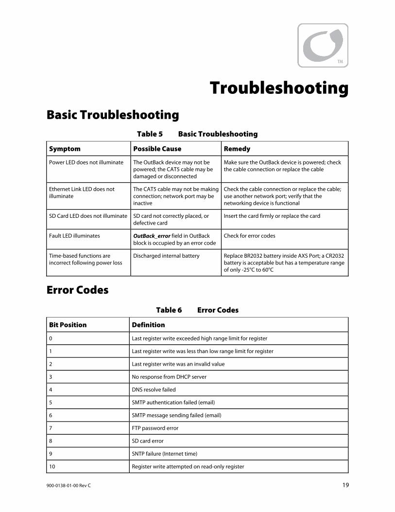
Troubleshooting Basic Troubleshooting
Table 5 Basic Troubleshooting
Symptom Possible Cause Remedy
Power LED does not illuminate The OutBack device may not be powered; the CAT5 cable may be damaged or disconnected
Make sure the OutBack device is powered; check the cable connection or replace the cable
Ethernet Link LED does not illuminate
The CAT5 cable may not be making connection; network port may be inactive
Check the cable connection or replace the cable; use another network port; verify that the networking device is functional
SD Card LED does not illuminate SD card not correctly placed, or defective card
Insert the card firmly or replace the card
Fault LED illuminates OutBack_error field in OutBack block is occupied by an error code
Check for error codes
Time-based functions are incorrect following power loss
Discharged internal battery Replace BR2032 battery inside AXS Port; a CR2032 battery is acceptable but has a temperature range of only -25°C to 60°C
Error Codes
Table 6 Error Codes
Bit Position Definition
0 Last register write exceeded high range limit for register
1 Last register write was less than low range limit for register
2 Last register write was an invalid value
3 No response from DHCP server
4 DNS resolve failed
5 SMTP authentication failed (email)
6 SMTP message sending failed (email)
7 FTP password error
8 SD card error
9 SNTP failure (Internet time)
10 Register write attempted on read-only register

Troubleshooting
20 900-0138-01-00 Rev C
This page intentionally left blank.
900-0138-01-00 Rev C 21
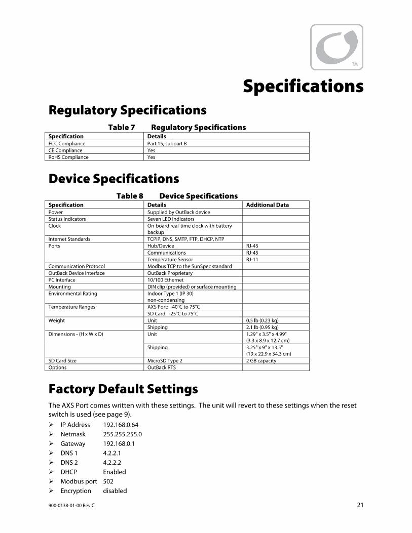
Specifications Regulatory Specifications
Table 7 Regulatory Specifications Specification DetailsFCC Compliance Part 15, subpart B CE Compliance Yes RoHS Compliance Yes
Device Specifications Table 8 Device Specifications
Specification Details Additional DataPower Supplied by OutBack device Status Indicators Seven LED indicators Clock On-board real-time clock with battery
backup
Internet Standards TCPIP, DNS, SMTP, FTP, DHCP, NTP Ports Hub/Device RJ-45
Communications RJ-45 Temperature Sensor RJ-11
Communication Protocol Modbus TCP to the SunSpec standard OutBack Device Interface OutBack Proprietary PC Interface 10/100 Ethernet Mounting DIN clip (provided) or surface mounting Environmental Rating Indoor Type 1 (IP 30)
non-condensing
Temperature Ranges AXS Port: -40°C to 75°C SD Card: -25°C to 75°C
Weight
Unit 0.5 lb (0.23 kg) Shipping 2.1 lb (0.95 kg)
Dimensions - (H x W x D)
Unit 1.29" x 3.5" x 4.99" (3.3 x 8.9 x 12.7 cm)
Shipping 3.25" x 9" x 13.5" (19 x 22.9 x 34.3 cm)
SD Card Size MicroSD Type 2 2 GB capacity Options OutBack RTS
Factory Default Settings The AXS Port comes written with these settings. The unit will revert to these settings when the reset switch is used (see page 9). IP Address 192.168.0.64 Netmask 255.255.255.0 Gateway 192.168.0.1 DNS 1 4.2.2.1 DNS 2 4.2.2.2 DHCP Enabled Modbus port 502 Encryption disabled

Specifications
22 900-0138-01-00 Rev C
This page intentionally left blank.

900-0138-01-00 Rev C 23
This page intentionally left blank.

900-0138-01-00 Rev C
Masters of the Off-Grid.™ First Choice for the New Grid.
Corporate Headquarters 17825 – 59th Avenue N.E. Suite B Arlington, WA 98223 USA +1.360.435.6030
European Office Hansastrasse 8 D-91126 Schwabach, Germany +49.9122.79889.0