
AXLT
53
AXLT155 Linear tables Linear table with screw-type drive and rail guide
-
Upload
leonardo-alex -
Category
Documents
-
view
5 -
download
0
description
bbbbbbbbbbb bbbbbbbb
Transcript of AXLT

AXLT155
Linear tables
Linear table with screw-type drive and rail guide

Basic massMass per 100 mm strokeSled mass
Ball screw Trapezoidal screw thread
Movement speedRepeat accuracyDyn. load rating ball screwNo-load torqueMoments of inertia:
Lead 5 mmLead 20 mmLead 50 mm
Max. overall length
Loads [N]PR
PL
PT
Load torques [Nm]MA
MB
MC
I N D U S T R Y
SNR Industry
45
PRPT
PL
MA
MC
MB
AXLT155
Linear table with screw-type drive and rail guide
max. 2 m/s0,03 mm
9,1 bis 17,5 kN 1)
0,6 - 0,8 Nm
0,84 kgcm2/m0,81 kgcm2/m0,79 kgcm2/m
3,5 m
Technical data Drive elementsDiameter20 mm20 mm
Lead5, 20 mm4, 8 mm
dyn.690069006900
280280340
stat190001900019000
790790950
dyn.690069006900
420420340
stat190001900019000
11001100950
Rail guideH15 H15*
Loads and load torques*
H15*
6,2 kg1,2 kg2,3 kg
H155,5 kg1,2 kg2 kg
MassSchienenführung
* Table length: 220 mm
* Table length: 220 mm* Max. permitted loads in accordance with definition on page 17.See from page 9 onwards for load ratings for individual lifetime calculation.
1) Depending on the design of the screw-type drive.
0
1000
2000
3000
4000
5000
6000
7000
500 1000 1500 2000 2500
Spee
d[1
/min
.]
Stroke length [mm]
Subject to technical changes.

AXLT225
Linear tables
Linear table with screw-type drive and rail guide

Basic massMass per 100 mm strokeSled mass
Ball screwTrapezoidal screw thread
Movement speedRepeat accuracyDyn. load rating ball screwNo-load torqueMoments of inertia:
Lead 5 mmLead 10 mmLead 25 mm
Max. overall length
Loads [N]PR
PL
PT
Load torques [Nm]MA
MB
MC
I N D U S T R Y
SNR Industry
47
PRPT
PL
MA
MC
MB
H20 *
15,8 kg1,8 kg6,0 kg
H2013,0 kg1,8 kg5,0 kg
MassRail guide
Diameter25 mm24 mm
Drive elementsLead
5, 10, 25 mm5, 10 mm
max. 2 m/s0,03 mm
14,7 bis 15,9 kN 1)
0,7 - 1,2 Nm
2,22 kgcm2/m2,39 kgcm2/m2,15 kgcm2/m
3,5 m
Technical data
AXLT225
Linear table with screw-type drive and rail guide
dyn.109001090010900
720720810
stat300003000030000
200020002250
dyn.109001090010900
930930810
stat300003000030000
260026002250
Rail guideH20 H20 *
Loads and load torques*
* Table length: 320 mm* Max. permitted loads in accordance with definition on page 17.See from page 9 onwards for load ratings for individual lifetime calculation.
1) Depending on the design of the screw-type drive.
0
500
1000
1500
2000
2500
3000
3500
4000
4500
5000
Spee
d[1
/min
.]
500 1000 1500 2000 2500
Stroke length [mm]
* Table length: 320 mm
Subject to technical changes.

AXLT325
Linear tables
Linear table with screw-type drive and rail guide

Basic massMass per 100 mm strokeSled mass
Ball screwTrapezoidal screw thread
Movement speedRepeat accuracyDyn. load rating ball screwNo-load torqueMoments of inertia:
Lead 5 mmLead 10/20 mm
Lead 32 mmMax. overall length
Loads [N]PR
PL
PT
Load torques [Nm]MA
MB
MC
I N D U S T R Y
SNR Industry
49
PRPT
PL
MA
MC
MB
H30 *38,7 kg3,5 kg14,6 kg
Linear table with screw-type drive and rail guide
AXLT325
dyn.220002200022000
200020002250
stat530005300053000
490049005500
dyn.220002200022000
270027002250
stat530005300053000
650065005500
Rail guideH30 H30 *
Loads and load torques*
max. 2 m/s0,03 mm
19,5 bis 31,7 kN 1)
1,1 - 1,5 Nm
6,05 kgcm2/m6,40 kgcm2/m6,17 kgcm2/m
3,2 m
Technical data Drive elementsDiameter32 mm36 mm
Lead5, 10, 20, 32
6, 12 mm
H3031,5 kg3,5 kg12,0 kg
MassRail guide
* Table length: 450 mm
* Table length: 450 mm* Max. permitted loads in accordance with definition on page 17.See from page 9 onwards for load ratings for individual lifetime calculation.
0
500
1000
1500
2000
2500
3000
3500
4000
750 1250 1750 2250 2750
Stroke length [mm]
Spee
d[1
/min
.]
1) Depending on the design of the screw-type drive.
Subject to technical changes.

AXLT455
Linear tables
Linear table with screw-type drive and rail guide

Basic massMass per 100 mm strokeSled mass
Ball screwTrapezoidal screw thread
Movement speedRepeat accuracyDyn. load rating ball screwNo-load torqueMoments of inertia:
Lead 5 mmLead 10 mmLead 20 mmLead 40 mm
Max. overall length
Loads [N]PR
PL
PT
Load torques [Nm]MA
MB
MC
I N D U S T R Y
SNR Industry
51
Linear table with screw-type drive and rail guide
AXLT455
dyn.300003000030000
370037003950
stat770007700077000
9500950010000
Rail guideH35
Loads and load torques*
max. 2 m/s0,03 mm
29,1 bis 54,3 kN 1)
1,7 - 2,8 Nm
15,64 kgcm2/m13,55 kgcm2/m13,52 kgcm2/m13,42 kgcm2/m
3,2 m
Technical data
Mass74 kg6,3 kg29 kg
0
500
1000
1500
2000
2500
3000
3500
750 1250 1750 2250 2750
Stroke length [mm]
Spee
d[1
/min
.]
1) Depending on the design of the screw-type drive.
Drive elementsDiameter40 mm40 mm
Lead5, 10, 20, 40 mm
7 mm
PRPT
PL
MA
MC
MB
* Max. permitted loads in accordance with definition on page 17.See from page 9 onwards for load ratings for individual lifetime calculation.
Subject to technical changes.

Basic massMass per 100 mm strokeSled mass
Movement speed Repeat accuracy Drive elements Stroke per revolution:Permitted dyn. operating forceOverall lengthGeometrical moment of inertia IxGeometrical moment of inertia Iy
Loads [N]PR
PL
PT
Load torques [Nm]MA
MB
MC
I N D U S T R Y
SNR Industry
63
max. 3,3 m/s0,05 mm
rack, module 5400 mm16240 N
10 m14645 cm4
7958 cm4
PR
PT
IXIY
PL
MA
MC
MB
Lifting axis with rack drive and rail guide
AXS280-M400
Technical data
Mass*96,0 kg5,9 kg54,5 kg
* Masses without gearbox
dyn.280002800028000
430043003000
stat100000100000100000
155001550010500
Rail guideH35
Loads and load torques*
* Max. permitted loads in accordance with definition on page 17.See from page 9 onwards for load ratings for individual lifetime calculation.
Subject to technical changes.

AXS280-Z
Gantry axes
Gantry axis with toothed belt drive and rail guide

Rail guide Rail guide Rail guideS/H 30 S/H 35
Basic mass 73 kg 78 kgMass per 100 mm stroke 4,3 kg 4,6 kgSled mass 19 kg 19 kg
Movement speedRepeat accuracyDrive elementsStroke per revolution:Permitted dyn. operating forceNo-load torqueMoment of inertia Overall lengthGeometrical moment of inertia IXGeometrical moment of inertia IY
Loads [N]PR
PL
PT
Load torques [Nm]MA
MB
MC
I N D U S T R Y
SNR Industry
65
PR
PT
IXIY
PL
MA
MC
MB
Gantry axis with toothed belt drive and rail guide
AXS280-Z
max. 6 m/s
0,05 mm
Toothed belt 75 AT10
4000 N
480 mm
9 Nm
227,6 kgcm2
10 m (one-piece)1)
14.645 cm4
7.958 cm4
Technical data
1) Greater length on request
Mass
dyn. 18000110009900
175012001150
stat. 420002100018000
340022002200
dyn.174001740017400
210021001850
stat.53000
53000
53000
650065005700
Rail guide
S30
dyn. 250001530013800
245016501600
stat. 570002850024500
460030003000
Rail guide
S35dyn.
240002400024000
295029502600
stat. 770007700077000
940094008300
Rail guide
H35Rail guide
H30
Loads and load torques*
* Max. permitted loads in accordance with definition on page 17. See from page 9 onwards for load ratings for individual lifetime calculation.
Subject to technical changes.

AXS280-M200
Gantry axes
Gantry axis with rack drive and rail guide

Basic massMass per 100 mm strokeSled mass
Movement speed Repeat accuracy Drive elements Stroke per revolution:Permitted dyn. operating forceOverall lengthGeometrical moment of inertia IxGeometrical moment of inertia Iy
Loads [N]PR
PL
PT
Load torques [Nm]MA
MB
MC
PR
PT
IXIY
PL
MA
MC
MB
Gantry axis with rack drive and rail guide
I N D U S T R Y
SNR Industry
67
AXS280-M200
max. 3,3 m/s0,05 mm
rack, module 2
200 mm3190 N
10 m 1)
14645 cm4
7958 cm4
Technical data
1) Greater length on request.
dyn.250001530013800
310020001600
stat570002850024500
580035003000
dyn.240002400024000
350035002600
stat770007700077000
11200112008300
Rail guideS35 H35
Loads and load torques*
Mass*52,0 kg4,9 kg16,5 kg
* Masses without gearbox
* Max. permitted loads in accordance with definition on page 17.See from page 9 onwards for load ratings for individual lifetime calculation.
Subject to technical changes.

AXS460-M250
Gantry axes
Gantry axis with rack drive and rail guide

Basic massMass per 100 mm strokeSled mass
Movement speed Repeat accuracy Drive elements Stroke per revolution:Permitted dyn. operating forceOverall lengthGeometrical moment of inertia IxGeometrical moment of inertia Iy
Loads [N]PR
PL
PT
Load torques [Nm]MA
MB
MC
PR
PT
IXIY
PL
MA
MC
MB
Gantry axis with rack drive and rail guide
AXS460-M250
I N D U S T R Y
SNR Industry
69
max. 6 m/s0,05 mm
rack, module 3
250 mm5860 N10 m 1)
88490 cm4
54170 cm4
Technical data
1) GrGreater length on request.
dyn.280002800028000
580058004500
stat100000100000100000
210002100016000
Rail guideH35
Loads and load torques*
Mass*139,5 kg
8,9 kg46,5 kg
* Masses without gearbox
* Max. permitted loads in accordance with definition on page 17.See from page 9 onwards for load ratings for individual lifetime calculation.
Subject to technical changes.

Integrated planetary gears
AXC/AXLT drive adaptation
To meet the highest demands in terms of accuracy and dynamics, our AXC line with inte-grated planetary gears is available. In the 60 size, the planetary gear is integrated directly inthe belt pulley of the toothed belt drive. In the 80 and 120 sizes, a belt pulley mounted onthe output shaft of the gear ensures torque transmission free from backlash actuated byadherence. Direct assembly removes the need for a coupling box and coupling, giving ourlinear axes extremely compact dimensions.
With particularly high positioning demands, the gears in sizes AXC80 and AXC120 are available with a reduced circumferential backlash of 3 or 5 angular minutes.
AXC 60 AXC40, 80 and 120
AXC40, 80 and 120AXC60

AXC40 AXC60
Single stage 5 10 4 9Two stage 25; 50 100 20; 40
Rated output torque [Nm] 6 5,5 6 5,5Accelerated output torque [Nm]1) 12 11 12 11Rated input speed [min-1] 4000 4000Max. input speed [min-1] 8000 8000
Single stage 12 6Two stage 15 9
Single stage 0,06 0,06Two stage 0,052 0,09
Single stage 0,75 0,45Two stage 0,92 0,62
Shaft height H [mm] 24,9 32,5Flange diameter D [mm] 55 70 65 85Reference circle e1 [mm] 55-63 63-75 63 - 75 85 - 100Motor shaft d (max.) [mm] 11 14 11 14
Single stage 74 79 23,5 29,5Two stage 90 95 43 50
AXC80 AXC120
Single stage 3 4; 5; 7 10 3 4; 5; 7 10Two stage
Rated output torque [Nm] 56 70 45 135 170 110Accelerated output torque [Nm]1)
Rated input speed [min-1] 2300 2900-4500 3100 2000 2500-4200 2500Max. input speed [min-1] 6000 4800
Single stage 6 (reduced 3) 6 (reduced 3)Two stage 8 (reduced 5) 8 (reduced 5)
Single stage 0,34 - 0,94 1,15 - 3,75Two stage 0,11 - 0,48 0,33 - 1,79
Single stage 3,8 7,8Two stage 4,2 8,3
Shaft height H [mm] 43,5 62,5Single stage 95 125 125Two stage 75 95 115
Reference circle e1 [mm] 70-100 115 130 165 70-100 115 130 165 215Motor shaft d (max.) [mm] 14 19 24 19 24 32
Single stage 110 110 120 119 119 129Two stage 122 137 147 136 240 162
I N D U S T R Y
SNR Industry
71
Circumferential backlash [arcmin]
Mass moment of inertia [kgcm2]
Mass [kg]
Overall length L [mm]
12; 16; 20; 28; 35; 50; 70
12; 16; 20; 28; 35; 50; 70
1) Note permissible operating load of the linear axis!
1) Note permissible operating load of the linear axis!
115 130
80 100 80
100 100
200 250 200
140 140130 200
Multiplication
Multiplication
Mass moment of inertia [kgcm2]
Mass [kg]
Flange diameter D [mm]
Overall length L [mm]
Circumferential backlash [arcmin]

The drives are directly connected via a coupling with the journal of the screw-type drive.
The drive is fixed via a separate coupling box.
AXC40 – 120 drive adaptation
AXLT155-455 drive adaptation
AXC/AXLT drive adaptation
Coupling box for screw-type drive

Linear axis Motor e1 e1 b1 b1 j d d i2 i2-l k L1 Torquedesign min. max. min. max. min. max. max. max.
AXC40-S B5 / B14 45 63 35* 50 - 5 14 30 7 55 47 7,5 NmB5 (B14) 63 (75) 100 50* 80 - 9 19** 40 3 82 71 10 Nm
B5 115 130 95 95 - 19 20 40 15 110 84 10 NmB5 130 130 110 110 - 24 24 50 25 120 93 10 Nm
B5 / B14 63 100 50 80 > 40 9 19** 40 0 82 73 17 NmB5 115 130 95 95 > 40 19 20 40 15 110 88 17 NmB5 130 130 110 110 - 24 24 50 25 120 98 17 Nm
AXC120-S B5 / B14 75 130 60* 110 - 14 24** 50 3 112 89 60 NmAXLT155 B5 / B14 55 100 34* 80 - 5 14 30 7 85 71 10 Nm
B5 / B14 63 100 50 80 > 40 9 19** 40 0 82 73 17 NmB5 115 130 95 95 - 19 20 40 15 110 88 17 NmB5 130 130 110 110 - 24 24 50 25 120 98 17 Nm
AXLT325 B5 / B14 75 130 60* 110 - 14 24** 50 3 112 89 60 NmB5 / B14 100 165 80* 130 - 19 25 50 8 140 105 160 NmB5 / B14 130 165 110 130 - 28 32 60 23 155 120 160 NmB5 / B14 215 215 180 180 - 38 38 80 45 192 142 160 Nm
I N D U S T R Y
SNR Industry
73
AXC60-S
AXC80-S
AXLT225
AXLT455
* Motors with smaller centring can also be used. Centring then takes place via the coupling.** For motors with feather key with maximum shaft length a shorter feather key will be supplied for exchange.

In order also to be able to optimally utilise the available room in tight spaces, we also offerdeflection belt drives for the linear axes with screw-type drive as well as for the linear tables.This makes it possible to adjust the installation position of the drive to suit the environmentalconditions.
AXLT with deflection belt drive
AXC with deflection belt drive
AXC/AXLT drive adaptation
Deflection belt drive for screw-type drive

AXC60 / AXLT155 1 1,5 1,8 2,2514 - - - 14 14 - 11 14 - 9 9
AXC80 / AXLT225 1 1,25 1,5 2 2,516 24 24 14 19 19 10 16 16 - 12 12 - 9 9
AXC120 / AXLT325 1 1,2 1,5 2 2,4 324 - - 19 24 24 14 24 24 9 19 19 - 14 19 - 9 14
AXLT455 1 1,25 1,6 228 - - 28 - - 28 - - 19 28 28
AXC60 50* 60 63 75 20 30 B5 106 ± 6 35 60 197 40 45AXLT155 50* 60 63 75 20 30 B5 140,5 ± 2 31,5 60 216 40 45AXC80 / AXLT225 50* 80 63 100 20 50 B5 185 ± 2,5 39 80 267 60 67AXC120 / AXLT325 60* 110 75 130 30 50 B5 / B14 249,5 ± 5,5 57 100 407 60 67AXLT455 80* 130 100 165 30 60 B5 / B14 354 ± 5 89 180 565 80 89
Linear axis Available ratios with the relevant maximum possible motor shaft diameters (Ø d) for the following fixing variants:
Clamping set / feather key / adhesive joint
I N D U S T R Y
SNR Industry
75
Linear axis Motor limiting dimensions (min/max) DimensionsØ b1 Ø e1 i2 Design a a1 b h t t1
* Motors with smaller centring (Ø b1) can also be used. Centring via the motor adapter is not required in this case.

AXC/AXLT drive adaptation
Adapter/coupling box for toothed belt driveWith the simplest form of connection, the output shaft of the gearbox or motor is inserteddirectly into the hollow shaft of the drive belt pulley. The drive is bolted to the linear axis viaa flat adapter plate. The force transmission takes place positively via the feather key. Theprerequisite here is that the output shaft diameter corresponds to the respective hollow shaftdiameter of the axis (see axis datasheet).
Adaptation via the integrated coupling in combination with a coupling box is however universal. The coupling on the axis side is bolted to the drive belt pulley and offers optimaloperational reliability, even at high dynamic performance, through its torque transmissionactuated by adherence. A wide selection of coupling boxes are available for commercial drives with a standardised B5 flange.

AXC40-Z B5 63 45° 4 x M4x8 40 6 10 23 7 54 72 37,5B14 52 45° 4 x Ø5,5 40 14 14 47 5 60 - 5B14 54 0° 4 x Ø6,5 44 14 14 60 18 70 80 18B14 65 0° 4 x Ø6,5 44 15 18 52 21 - 80 71B14 70 45° 4 x Ø5,5 60 14 24 40 15 64 80 65
B5 / B14 80 0° 4 x M6x15 60 12 18 34 3 - 100 53B14 80 0° 4 x Ø6,5 68 20 24 46 21 - 90 71
B5 C120 100 45° 4 x M6x8 80 14 14 50 8 100 120 8B14 61 90° 6 x Ø5,5 48 20 20 71 12 80 - 12B14 65 0° 4 x Ø6,5 44 15 25 50 16 80 100 74,5B14 70 0° 4 x Ø6,5 55 (invers) 20 20 69 10 82 100 10B14 80 0° 4 x Ø6,5 68 22 25 52 22 80 90 81B14 99 45° 4 x Ø8,5 60 10 28 44 7 85 115 66
B5 C120 100 45° 4 x M6x15 80 14 19 40 3 83 110 62B5 C120 100 45° 4 x M6x12 80 20 20 72 12,5 - 120 12,5
B5 115 45° 4 x M8x15 95 19 25 53 16 105 140 75B5 C160 / B14 130 45° 4 x M8x16 110 19 25 52 15 120 150 74
B14 90 0° / 90° 6 x Ø9 70 30 30 108 14 120 150 14B5 C120 100 45° 4 x M6x18 80 19 25 50 7 120 150 72B5 C120 100 45° 4 x M6x12 80 30 30 107 13 120 - 13
B14 100 0° / 90° 6 x Ø9 80 (invers) 30 30 106 12 120 150 11,5B5 C160 130 0° / 30° 12 x M8x12 110 30 30 107 13 - 160 13B5 C200 165 45° 4 x M10x20 130 30 30 119 25 - 200 25
Linear axis Design e2 α s1 b2 d d i2 . i2-l k2 a2 L2min. max. max max
I N D U S T R Y
SNR Industry
77
AXC60-Z / -A
AXC80-Z / -A
AXC120-Z / -A

Linear axis a b c d h6 d2 e f g i l s
AXC40-Z 23 26H7 x 1 1 10 M4 x 7 34 9,9 8,1 29,5 30 M3 x 5AXC60-Z / -A 34 47H7 x 1 1 14 M5 x 8 54 22,5 17,5 30 30 M5 x 6AXC80-Z / -A 42 68H7x 2 2 20 M6 x 10 72 23 20,5 39,3 40 M5 x 9AXC120-Z / -A 61 102H8 x 2 104 42,5 42,5 M8 x 12AXC120-A * Ø162 110H8x3,5 Ø130 - - M8 x 13
AXC/AXLT drive adaptation
Fixing dimensions/plug-in shaft for toothed belt driveIf the user is carrying out drive adaptation, the intended mounting site must be specifiedwith the order as the axis profile is machined to provide an optimal seat for the drive adapter.The appropriate sliding blocks for drive fixing are included in the scope of delivery.
M10 x 172 30 59,5 60
* Illustration see dimension sheet page 40.

Linear axis Dimensions Clamping hub Tension hubdw Lw A min.1) A DKM 2) D LK l1 d d TA d d TA
min. max. [Nm] min. max. [Nm]
31 11 8 14 1,34 - - -38 19 - - - 10 14 1,34
AXC60-..K 22x2 A - 110 188 120+2 40 50 25 12 24 10,5 10 20 3AXC80-..K 28x2,5 A - 137 230 154(160)+3 55 59 30 12 28 10,5 15 28 6AXC120-..K A - 180 285 198+3 65 35 18 38 6AXC120-..P..K A - 140 245 158+3 25 - - - -
I N D U S T R Y
SNR Industry
79
38x4 65 20 38 25
Axes configured in parallel may be coupled via a connecting shaft in order to transfer thetorque from the axis driven by the motor to the second axis.
AXC40-ZK 14x2 A - 79 125 87+2 30
1) with option of removal without disassembling the linear axes2) DKM= Special design with double-gimballed centre
Coupling and connecting shaft

Switches
Switch attachment on AXC/AXLTDepending on the requirement, mechanical switches with various IP protection ratings andinductive proximity switches with conventional output circuits are available.
The mechanically activated switches are usedin all cases to switch off the drive in an emer-gency, before the mechanical end stop shockabsorbers are reached. These can also becombined with external inductive proximityswitches to set additional switching pointsfor reference runs for example.
Our inductive proximity switches for slot installation are the most compact variants.They finish flush with the surface of the aluminium profile of the axis and form almostno interference contours. The switches areavailable as PNP NC/NO contacts or NPNNC/NO contacts.
Professional cabling can be simply carriedout with the sensor boxes available as standard. All switching signals are consoli-dated here.With the aid of conventional pre-assembledcables, the connection to the signal-processing controller can be established very quickly.

M2 22 19,5 25 11,5 -M3 20 12,5 18 19 -
AXC60-A M1 30 9,5 18 55 -AXC80 M1 30 25,5 26 11 -AXC120 M1 30 64,5 26 20 -AXLT155 M3 25 1 - - -AXLT225 M3 25 11 - - 5AXLT325 M3 35 26 - - 10AXLT455 M3 34 39,5 - - 14
Linear axis Switches A B C D E
I N D U S T R Y
SNR Industry
81
Mechanical switches AXC60-120/AXLT155-455
AXC60-S / -Z

Switches
Switch attachment on AXC/AXLT
Inductive proximity switch AXC40 (externally mounted)
Inductive proximity switches AXC60-120 (externally mounted)

I N D U S T R Y
SNR Industry
83
Switch attachment on AXSAll AXS linear axis are available as standard with mechanical switches.Inductive proximity switches are also available for the AXS280-Z gantry axis.
Lifting axes AXS160-M to AXS280-M and telescopic axis AXS120
Gantry axis AXS280-Z
Gantry axes AXS280-M and AXS460

Depending on the number of switches required, either a 2-part distributor can be used or asensor box to which four or more switches can be connected. Both designs have an IP67protection rating and are supplied completely wired as shown in the illustration.A 14-pin connector with M16 thread for the sensor box or a 5-pin connector with M8 threadfor the 2-part distribution block are available for connection to signal-processing control.
To avoid interference contours, the sensor box on the AXC120-S and AXLT325 can also bemounted under the motor adapter to save space.
Switches
Switches
Sensor box on AXC/AXLT
2-part distribution block Sensor box for 4 switches

Switch M1/M4/M5AXC60-A M20 x 1,5AXC80/120 Conductor cross section: AXS 0,5…2,5 mm2
3 x 10⁶ Screw connection 4 x M3,5Switching Conductor cross section:
cycles 0,5…1,5 mm2
Switch M3 10 x 106 Screw connectionAXC60-S/Z Switching Conductor cross section: AXLT155 – AXLT455 cycles max. 1,5 mm2
Switch M3.1 10 x 106 Soldered joint(Löt-Anschluß) Switching Conductor cross section: AXLT325 cycles max. 1,5 mm2
Service Housing Connection Protection life material class
Input supply Max. load Indexing Cable Protectionvoltage current precision length class
Switch I1NPN- /PNP- NO or NC contactAXC40 10...30 V DC 100 mA 2 M IP67AXLT155 – AXLT325AXSAXC-Initiator1)
PNP- Öffner / Schließer 3 u.NPN-Öffner 10 MAXC60-S/Z – AXC120-S/ZSwitch I2 ≤ 5% AXC60 – AXC120 Switch intervalSwitch I3 ≤ 5% boltingAXLT455 Switch interval wie M3
I N D U S T R Y
SNR Industry
85
Technical data for switchesMechanical switches
Inductive proximity switch
≤ 10%Switch interval
IP67
IP67
IP6710...30 V DC 130 mA
100 mA≤ 2%
Switch interval
1) With AXC60 max. 2 switches per sideWith AXC80 max. 3 switches per side
Control element: Jump feed switch (forced separation)/1x NC contact and 1x NO contact
Plastic
Plastic
Metal
Metal
30 x 106
Switchingcycles
Switch M2AXC60-S/Z
10...35 V DC
12...30 V DC 100 mA 3M
IP67
IP30
IP67
IP67

AXC40 AXC40-Fixing strip 55 - 28 40 5,5 10 7 - - - 13 382) 66AXC60 3) AXC60-Fixing strip 80 74 28 40 5,5 10 5 6,6 11 4 10 48 94AXC80 AXC80-Fixing strip 94 - 50 70 6,6 11 14 - - - 20 76 108
AXC120-Fixing strip 136 - 60 78 9 15 11,5 - - - 22 105 160Fixing strip 2 140 - 40 80 9 15 13 - - - 22 105 160Fixing strip 3 140 140 80 120 9 15 13 9 15 13 22 105 160
Linear axis Article description a1 a2 b c d1 D1 e1 d2 D2 e2 f g1) h
Fixing and connection elements
Fixing strips
AXC120 4)
1) Please note dimension K2 from the drive adapter or gearbox (see page 77) or dimension a of the drive-side machining (see page 78).2) with mounted coupling3) suitable for standard MB profiles in grid dimension 204) suitable for standard MB profiles in grid dimension 40
The number of fixing strips is dependent on the load and the length of the linear axis.
There is a range of optimally coordinated fixing elements available for the fixing of the different linear modules. Sliding blocks, fixing strips and adapters offer the broadest rangeof options for bolting our modules to mounting surfaces or to each other. The range is completed by gantry supports coordinated to the linear axes and axis systems.

Linear Article description Design s L L11) TA max. tensile
axis [Nm] load [N]
Sliding block 5 ST M3 E M3 12 3 1,5 500Sliding block 5 ST M4 E M4 12 4 3,0 500Sliding block 5 ST M5 E M5 12 4 4,5 500Sliding block 5 Zn M3 R M3 5 2,5 1,0 50Sliding block 6 ST M4 E M4 17 5 4,0 1750Sliding block 6 ST M5 E M5 17 5 8,02) 1750Sliding block 6 ST M6 E M6 17 5,5 142) 1750Sliding block 6 Zn M4 R M4 15 7,5 1,5 150Sliding block 8 ST M4 E M4 22 9 4,0 2500Sliding block 8 ST M6 E M6 22 9 142) 3500Sliding block 8 ST M8 E M8 22 9 25 5000Sliding block 8 Zn M4 R M4 19 9,5 1,5 250Sliding block 8 Zn M5 R M5 19 9,5 1,5 250Sliding block 8 ST M5 trafficking cash S M5 22 9 8,02) 2500Sliding block 8 ST M6 trafficking cash S M6 22 7 142) 3500Sliding block 8 ST M8 trafficking cash S M8 20 7 342) 5000Sliding block 12 ST M6 S M6 20 10 142) 3500Sliding block 12 ST M8 S M8 20 10 342) 6000Sliding block 12 ST M10 S M10 35 11,5 46 10000Sliding block DIN508-14 M8 S M8 22 11 342) 6000Sliding block DIN508-14 M12 S M12 22 11 85 10000
Design E• Standard sliding block• St galvanised• Can be swivelled into any position• Fixed via resilient ball
Design R• For efficient component mounting• Zn galvanised• Premounted on the component
and used in any position• Locked by turning the screw
Design S• Heavy duty sliding block• St galvanised• Insertion of profile end• Up to slot width 8.2 fixed
via resilient ball
I N D U S T R Y
SNR Industry
87
AXC120 AXLT155AXLT225AXS120T AXS160AXS200
AXS230AXS460
AXS280
AXC40AXC60
AXC80
1) Maximum values, deviating dimensions possible2) When utilising the maximum tightening torque, strength category 10.9 is necessary
Sliding blocks

X axis Y axisAXC40 AXC60 AXC80 AXC120
AXC-Direct- AXC-Direct-connection-40-40 connection-40-60
2x AXC-Direct- AXC-Direct- AXC-Direct-connection-60-60 connection-60-80 connection-60-120
AXC-Direct-connection-80-120
AXC-Direct-connection-120-120
AXC-Direct- 2 x fixing strip 2 (3)connection-60-60 + 4 (6) x M8x25 DIN912
2x sliding block.8 ST M6 4 (6) x sliding block.8 ST M8AXC-Direkt-
connection-60-80 +4x sliding block.8 ST M6
Fixing and connection elements
AXC direct connectionWe offer our users the ultimate in flexibility for the configuration of the axes in a multi-axissystem. A wide range of adapters in different designs are available for this. The connectionsets include all other necessary connection elements (e.g. adapter plates, screws etc.).
Y axis
X axis
See page 86 for fixing strip dimensions.
AXC60
AXC40
AXC80
AXC120
MB-ProfileRaster 40
MB-Profile Raster 50

AXC60 AXC40 90 90 58 10 AXC-Cross connection-60-40AXC60 AXC60 90 90 58 12 AXC-Cross connection-60-60AXC80 AXC60 190 180 47 11 AXC-Cross connection-80-60AXC80 AXC80 220 220 77 15 AXC-Cross connection-80-80AXC120 AXC80 280 220 116 20 AXC-Cross connection-120-80AXC120 AXC120 280 280 116 20 AXC-Cross connection-120-120
Y axis Z axis Ly Lz R T Order code
I N D U S T R Y
SNR Industry
89
AXC cross connection
Y axis
Alignment using parallel pinsor limit stop flange
Axis middle axis = centreSled plate
Note the mounting sides of the switches for the Y axis with AXC60 type
Z axis

X axis Y axis T1 U V X2 X3 Y3 Article description
AXC40 AXC60 8 20 -11 98 19 59 AXC gantry connection 40-60AXC80-Z 10 180 39 100AXC80-S / -A 22AXC80-Z 0 155 19 80AXC80-S / -A 10AXC120-Z -201)/ 10 194 16 140AXC120-S / -A -201)/ 25
AXS120 AXS280 30 - -401) 170 0 200 AXC gantry connection 80-120
Fixing and connection elements
AXC gantry connection
AXC60
AXC80
AXC80
1) Position on X-axis fixed with parallel pins.
Y axis
X axis
10
10
AXC gantry connection 120-280
AXC gantry connection 60-80
AXC gantry connection 80-80
40
-
615

AXC80 AXC60-A 78 45 130 64AXC80-A AXC60-A 78 20 130 64AXC120 AXC80-A 92 59 150 87,5AXC120-A AXC80-A 92 0 / 55 150 87,5
Y axis Z axis X1 Y1 Y2 Z1
I N D U S T R Y
SNR Industry
91
AXC-A standard connection
Z axis
Optionally fixed position coordinated on mounting as 3-axis system with direct connection to the X axis.
Y axis

X axis Y axisAXLT155 AXLT225 AXLT325 AXLT455
AXLT-direct connection-155-155
AXLT-direct connection- AXLT-direct connection-225-155 225-225
AXLT-direct connection- AXLT-direct connection-325-225 325-325
AXLT-direct connection- AXLT-direct connection-455-325 455-455
Fixing and connection elements
AXLT direct connectionThe AXLT linear tables are designed in such a way that they can be mounted as cross tablesin the simplest way. Depending on the size, an adapter may not be required.
Cross table variant in the base plate configuration on table top.
Linear tables of the same size or the next smallest size can be mounted on the table top inthis configuration. An adapter plate is not required in both cases.
Combination of identical sizes
Combination with next smaller size
AXLT155
AXLT225
AXLT325
AXLT455

AXLT crossconnection 155-155AXLT cross AXLT crossconnection 225-155 connection 225-155
AXLT cross AXLT cross AXLT crossconnection 325-225 connection 325-325 connection 325-325
AXLT cross AXLT crossconnection 455-325 connection 455-455
X axis Y axisAXLT155 (LT=220) AXLT225 (LT=320) AXLT325 (LT=320) AXLT325 (LT=450) AXLT455
I N D U S T R Y
SNR Industry
93
Cross table variant in the configuration table top on table top
The linear tables (X axis) can also either be combined with the identical or the next smallestsize in this configuration. From size 325 (X axis) an adapter plate is no longer required.
Combination of identical sizes
Combination with next smaller size
AXLT cross connection
AXLT155
AXLT225
AXLT325
AXLT455
LT = Table length in mm

Fixing and connection elements
SNR gantry supportThe SNR gantry supports can be used both with the AXC and the AXS lines.

AXC40 AXC60AXC80 PP Cover profile6.PP.black.2000L
PP Cover profile8.PP.black.2000LAl Cover profile8.3000L plain
PP Cover profil5.PP.black.2000L
Linear axis Material Article description
I N D U S T R Y
SNR Industry
95
Cover profileIn order to facilitate the cleaning of the linear axis or to prevent heavy soiling, the slots ofthe profile body can be closed with appropriate cover profiles.
AXC120
Channel cover for AXC
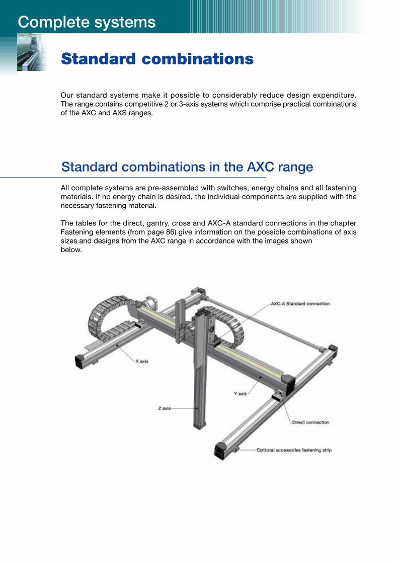
Standard combinations
Complete systems
Standard combinations in the AXC range
Our standard systems make it possible to considerably reduce design expenditure. The range contains competitive 2 or 3-axis systems which comprise practical combinationsof the AXC and AXS ranges.
All complete systems are pre-assembled with switches, energy chains and all fasteningmaterials. If no energy chain is desired, the individual components are supplied with the necessary fastening material.
The tables for the direct, gantry, cross and AXC-A standard connections in the chapterFastening elements (from page 86) give information on the possible combinations of axissizes and designs from the AXC range in accordance with the images shown below.

I N D U S T R Y
SNR Industry
97
Standard combinations in the AXC and AXS rangeWith large stroke lengths and increasing requirements for load capacity and stiffness, weoffer the optimum alternative with a standard combination from the AXC and AXS program.

Complete systems
Standard combination in the AXS rangeIn the upper load area, our standard systems from the AXS range are available.
Standard layout with gantry axis driven by toothed belt
Standard layout with gantry axis with rack drive

AXS160-M160-G30 •AXS200-M200-x30 •AXS200-M250-x30 •AXS230-M320-H30 • • •AXS280-M400-H35 •AXS120T-M400-H25 • •
Z axis
AXS280-ZGxx-x30 AXS280-ZGxx-x35 AXS280-M200-x3x AXS460-M250-H35
AXS280-ZGx-x30 AXS160-M160-G30 657 550 620 215 46 342 445 160 160AXS200-M200-x30 725 610 680 215 51 382 520 200 200AXS230-M320-H30 515 312 420 215 70 442 581 350 350AXS200-M250-x30 490 375 445 215 82,5 375 528 283 295AXS230-M320-H30 515 312 420 215 70 442 581 350 350AXS230-M320-H30 695 492 600 210 70 598 737 350 350AXS280-M400-H35 690 493 600 210 70 612 752 355 355
Y axis Z axis K L L1 L2 L3 L4 L5 L6 L7
I N D U S T R Y
SNR Industry
99
AXS280-ZGx-x35
AXS280-M200-x35
AXS460-M250-H35
Limit stop can bedropped if the functionis fulfilled by customerapplication (J=0).
Rac
kdr
ive
Overview of AXS combinations
Y axis
Toothed belt drive Rack drive

B15i.038.075 75 • 38 17 1500 1 •B15.5.110 110 • 63 17 1500 1 • • •B15i.5.110 110 • 63 17 1500 1 •240.07.75 75 • 77 25 3000 2 •240.07.100 100 • 77 25 3000 2 • •240.07.125 125 • 77 25 3000 2 • • • • •250.07.125 125 • 77 25 3000 2 • • •240.10.125 125 • 103 25 3000 2 • • • •250.12.125 125 • 125 25 3000 2 • •27.12.175 175 • 125 32 3500 3 • •1)
27i.12.125 125 • 125 32 3500 3 • • •27i.12.200 200 • 125 32 3500 3 •350.125.125 125 • 125 42 4000 3,5 • •1)
390.12.150 150 • • 125 38 5000 6 • •1) •410.11.135 135 • • 112 50 7000 12 • •1) •
medium Open Internal
radius dimension
[mm] [mm]
Complete systems
Overview of energy chains
Des
ign
inte
rnal
aex
tern
al
B H max
.str
oke
horiz
onta
lca
ntile
ver
[mm
]
Filli
ngm
ass
horiz
onta
lmax
.st
roke
kg/m
AX
C40
AX
C60
AX
C80
AX
C12
0
AX
S12
0T
AX
C60
AX
C80
AX
C12
0
AX
S28
0
AX
S46
0
AX
C60
-A
AX
C80
-A
AX
C12
0-A
AX
S12
0T
AX
S16
0
AX
S20
0
AX
S23
0
AX
S28
01) not for combination with Z axis AXS160.
Depending on the requirement, various designs of energy chains are available for the linearaxis systems.
X axis Y axis Z axis
Up to design 250.07 with internal dimension B=77 mm, a separating web is mounted every2nd link. From design 240.10 with internal dimension B=103 mm, two separating webs aremounted every 2nd link.
Up to design 350, the connection elements are prepared for fixing the cables using cableties. A C rail is mounted from design 390.

I N D U S T R Y
SNR Industry
101
Design examplesThe following design examples once again clarify the flexibility of our linear axis systems.

Size code for drive version
For toothed belt drive
– Shaft or hollow shaft diameter (HW, WL, WR, WD, FL, FR)
– Bore diameter of the coupling (KL, KR, GL, GR)
– Gear ratio (PL, PR)
– With the PLK or PRK design, only the gear ratio is specified.
For screw-type drive
Spindle diameter and lead
For rack drive
Feed constants: 160/200/250/320/400
Type code for SNR linear axes
Designation scheme
Type designationas specified in catalogue
Drive design
For toothed belt drive
HW: Hollow shaft
WL (WR): Free shaft end left (right)
WD: Free shaft end both sides
KL (KR): Integrated coupling drive side left (right)
PL (PR): Integrated planetary gears left (right)
PLK (PRK): Integrated planetary gears left
+ integrated coupling right
(Planetary gears right + coupling left)
GL (GR): Coupling and coupling box left (right)
FL (FR): Drive adapter flange (direct connection output shaft/
hollow shaft) left (right)
For spindle drive
G: Coupling box + coupling
U: Deflection belt drive
Not specified: free drive shaft
Subject to technical changes.
Ordering example AXC 60 – Z HW 14 – LR 24 – 1000 – 1278 – 00
Linear motion system
H: THK linear motion guide type SHS
S: THK linear motion guide type SSR
W: THK linear motion guide type SHW
S: THK linear motion guide type SRS
G: THK linear motion guide type GSR
R: THK linear motion guide type HR
Size of the linear motion systemas specified in catalogue
Stroke length
Overall length(stroke + additional length specified in catalogue)
Option codeIs assigned internally and is used toidentify options, attachments and anyspecial designs specified in plain text.
Drive typeZ: Toothed belt drive
A: Driven sleds
S: Screw-type drive
T: Trapezoidal screw thread
M: Rack drive
O: No drive

Axis designation X Y Z
Single axis / parallel (centre distance)
Installation position: horizontal/vertical
Effective stroke [mm]
Load capacity [kg]
Travel speed [m/s]
Acceleration [m/s2]
Optional travel time [sec]
Repeat accuracy mm
Desired service life strokes or hours
Cycle time sec
For larger loads and torque loads, please enclose a sketch!
I N D U S T R Y
SNR Industry
103
Your enquiry form
Central coordinates:
XYZ
Company
Street address
Contact Function/Department
Telephone Fax
Project designation
One-off requirement Quantity New design
Desired deadline CW Technical improvements
Series requirement Quantity/year Cost reduction – Price previously EUR
Desired deadline for Quantity CW
Application parameters
With drive, selection by SNRPlease enclose detailed specifications for the cyclic process.
Existing drive, make/type
Connecting cable length m (Please specify length)
Inductive proximity switch quantity
Mechanical limit stop quantity
Drive / Control
Date
Quotation by

Attachment for linear axis: AXplease check/enter as appropriate
Left-side attachments Right-side attachments
mechanical limit switch
IP30
IP67
inductive limit switch
NC contact (standard)
NO contact
NO reference switch
PNP (standard)
NPN
Switch mounting
Enquiry form
Mounting position angular gear Installation position linear axis Position motor connection
H
E
F
B
A VU
VO
KOKU
G
D
H
C

L I N E A R M O T I O N
SNR Industry
105
Notes

Notes


