
Axial Piston Variable Pump RE 92800/03.10 1 - Gerex · Axial Piston Variable Pump RE 92800/03.10...
32
Linear Motion and Assembly Technologies Service Pneumatics Hydraulics Electric Drives and Controls RE 92800/03.10 1/32 Axial Piston Variable Pump A15VSO Data sheet Series 10 Size 280 Nominal pressure 350 bar Peak pressure 420 bar Open circuit Features Axial piston pump in swashplate design for industrial hydro- – static drives in open circuit operation The flow is proportional to the input drive speed and dis- – placement. By adjusting the swashplate angle it is possible to infinitely – vary the the output flow from 0 its maximum value. With the specific control, 100% Mooring function (over – centre, operation as a motor) is possible. A wide range of suitable control options with various control – and regulating functions for all important applications. The universal through drive is suitable for mounting of gear – or axial piston pumps up to the same displacement size i.e. 100 %-through drive capability. Compact design – High efficiency – High power density – Low noise level – Contents Type code for standard program 2 Technical data 5 Power control 10 Displacement control 12 Pressure control 14 Dimensions size 280 18 Dimensions through drive 22 Summary through drive mounting options 27 Combination pumps A15VSO + A15VSO 28 Plugs for solenoids 29 Installation notes 30 General instructions 32
Transcript of Axial Piston Variable Pump RE 92800/03.10 1 - Gerex · Axial Piston Variable Pump RE 92800/03.10...

Linear Motion andAssembly Technologies ServicePneumaticsHydraulics
Electric Drives and Controls
Datenblatt
RE 92800/03.10 1/32Axial Piston Variable Pump A15VSO
Data sheet
Series 10Size 280Nominal pressure 350 barPeak pressure 420 barOpen circuit
FeaturesAxial piston pump in swashplate design for industrial hydro- –static drives in open circuit operation
The flow is proportional to the input drive speed and dis- –placement.
By adjusting the swashplate angle it is possible to infinitely –vary the the output flow from 0 its maximum value.
With the specific control, 100% Mooring function (over –centre, operation as a motor) is possible.
A wide range of suitable control options with various control –and regulating functions for all important applications.
The universal through drive is suitable for mounting of gear –or axial piston pumps up to the same displacement size i.e. 100 %-through drive capability.
Compact design –
High efficiency –
High power density –
Low noise level –
ContentsType code for standard program 2
Technical data 5
Power control 10
Displacement control 12
Pressure control 14
Dimensions size 280 18
Dimensions through drive 22
Summary through drive mounting options 27
Combination pumps A15VSO + A15VSO 28
Plugs for solenoids 29
Installation notes 30
General instructions 32

2/32 Bosch Rexroth AG A15VSO Series 10 RE 92800/03.10
Axial piston unit01 Swash plate design, variable, nominal pressure 350 bar, peak pressure 420 bar A15VS
Type of operation 28002 Pump, open circuit l O
Size (NG)03 ≈ Displacement Vg max in cm3 280
Control devices: Basis control1) 280
04
Power control fixed setting l LR
Override electro-proportional inverse proportional
U = 24 Vm L4
Displacement control electro-proportional U = 24 V l E2
pilot pressure inverse proportional
∆p = 35 bar m H5
Pressure control for one side of centre
fixed setting l DR
hydraulic remotely operated l DG
Pressure control with moor-ing function2)
fixed settingm MD
Additional control: Pressure control1)
(cannot be combined with Basis-pressure control)3) 280
05
Without additional control (no code) l
Pressure control for one side of centre
fixed setting l DR
hydraulic remotely operated l DG
Additional control: displacement control or unloading1)
(can be combined with Basis-power control only) 280
06
Without additional displacement control (no code) l
Displacement control electro- proportional U = 24 V l E2
pilot pressure inverse proportional ∆p = 35 bar m H5
Additional control: Load-Sensing1) 3) 280
07
Without additional Load-Sensing control (no code) l
Load-Sensing internal pump pressure
fixed setting l S0
1) The Basis control (04) can be combined with at most two additional controls (05, 06, 07)
2) Cannot be combined with E2 and H5 of Additional control: displacement control or unloading (06) 3) Cannot be combined with additional control DR and DG
Type code for standard program
A15VS O / 10 –01 02 03 04 05 06 07 08 09 10 11 12 13 14 15 16 17 18 19 20 21
= Available m = On request – = Not available = Preferred program

RE 92800/03.10 A15VSO Series 10 Bosch Rexroth AG 3/32
Pressureless initial position and external control pressure supply4) 280
08
Maximum swivel angle (Vg max), without external control pressure supply (standard for power and pressure control) l A
Maximum swivel angle (Vg max), with external control pressure supply (integrated shuttle valve) (standard for inverse proportional displacement control) l B
Minimum swivel angle (Vg min), with external control pressure supply (integrated shuttle valve) (standard for proportional displacement control) l C
Plug for solenoids5) 280
09Without l 0
HIRSCHMANN-plug l H
Swivel angle indicator 28010 With optical swivel angle indicator l V
Series11 Series 1, index 0 10
Threads for ports and flange connections 28012 Metric l M
Direction of rotation 280
13With view on drive shaft clockwise l R
counter clockwise m L
Seals 28014 FKM (fluor-caoutchouc) l V
Mounting flange 28015 SAE J744 165-4 (E) l E4
Drive shaft 280
16
Parallel keyed shaft to DIN 6885
Ø60l B4
Splined shaft to DIN 5480
W60x2x28x9l A4
Service line connections 28017 SAE-flange connection A on right side (45°) l 1
Execution of rotary group 28018 Optimized for low noise n = 1500 / 1800 rpm (standard) l E
4) For description see control devices 5) Plugs for other electric components can deviate
Type code for standard program
A15VS O / 10 –01 02 03 04 05 06 07 08 09 10 11 12 13 14 15 16 17 18 19 20 21
= Available m = On request – = Not available = Preferred program

4/32 Bosch Rexroth AG A15VSO Series 10 RE 92800/03.10
Through drive
19
Flange ISO 3019-1 (SAE J744) Splined shaft coupler
Mounting version
Diameter Symbol6) Designation Diameter Designation 280Prepared for through drive, closed with pressure tight cover l U000
82-2 (A)A1 5/8 in 9T 16/32DP S2 l A1S2
A2 5/8 in 9T 16/32DP S2 m A2S2
101-2 (B)
B1 7/8 in 13T 16/32DP S4 l B1S4
B2 7/8 in 13T 16/32DP S4 m B2S4
B57/8 in 13T 16/32DP S4 m B5S4
1 in 15T 16/32DP S5 m B5S5
127-2 (C)
C11 1/4 in 14T 12/24DP S7 m C1S7
1 1/2 in 17T 12/24DP S9 m C1S9
C21 1/4 in 14T 12/24DP S7 l C2S7
1 1/2 in 17T 12/24DP S9 m C2S9
152-4 (D) D4 1 3/4 in 13T 8/16DP T1 m D4T1
165-4 (E) E42 1/4 in 17T 8/16DP T3 m E4T3
W60x2x28x9 A4 l E4A4
Flange ISO 3019-2 (metric) Splined shaft coupler
Mounting version
Diameter Symbol6) Designation Diameter Designation 280
100-2 L5 1 in 15T 16/32DP S5 m L5S5
160-4 P4 1 1/4 in 14T 12/24DP S7 m P4S7
180-4 R41 1/2 in 17T 12/24DP S9 m R4S9
1 3/4 in 13T 8/16 DP T1 m R4T1
Pressure sensors and other sensors 28020 Without l 0
Standard-/special version
21
Standard version 0combined with attachment part or mounted pump K
Special version S
Note Short designation X refers to a special version not covered by the ordering code.
6) Layout of threaded bolt holes viewing on through drive end
Type code for standard program
A15VS O / 10 –01 02 03 04 05 06 07 08 09 10 11 12 13 14 15 16 17 18 19 20 21
= Available m = On request – = Not available = Preferred program

RE 92800/03.10 A15VSO Series 10 Bosch Rexroth AG 5/32
Technical dataHydraulic fluidFor extensive information on the selection of hydraulic fluids and application conditions consult our data sheet RE 90220 (mineral oil).
The variable pump A15VSO has been released for operation on mineral oils.
For operation on ecologically acceptable fluids or HF-fluids please consult us. When ordering please state the fluid to be used.
Selection diagram
tmin = -40 °C tmax = +115 °C
-40° -25° -10° 10° 30° 50° 90° 115°70°0°5
10
4060
20
100
200
400600
10001600
-40° 0° 20° 40° 60° 80° 100° -20°1600
νopt
16
36
VG 22
VG 32
VG 46
VG 68
VG 100
5
Fluid temperature range
Temperature t in °C
Visc
osity
ν in
mm
2 /s
Notes on the selection of hydraulic fluids
In order to select the correct fluid, it is necessary to know the operating temperature in relation to the ambient temperature: in an open circuit the tank temperature.
The hydraulic fluid should be selected so that within the operat-ing temperature range, the viscosity lies within the optimum range (νopt); see shaded section in the selection diagram. We recommend, that the higher viscosity grade is selected in each case.
Example: at an ambient temperature of X° C the operating temperature in the tank is 60° C. In the optimum viscosity range (νopt ; shaded area), this corresponds to grades VG 46 or VG 68; select: VG 68.
ImportantThe case drain temperature is influenced by pressure and speed, and is always higher than the tank temperature. At no point in the system may the temperature be higher than 110 °C, however. For the viscosity conditions in the bearing area, the temperature difference as stated below must be observed.
If the above conditions, due to extreme operating parameters cannot be met, please consult us.
Viscosity and temperatue
Viscosity [mm2/s] Temperature RemarkTransport + storage
Tmin ≥ -50 °C Topt = +5 °C to +20 °C
to 12 months with factory made preservation to 24 months with factory made long-time preservation
(Cold) Start1) νmax = 1600 TSt ≥ -40 °C t ≤ 3 min, light load (20 bar ≤ 50 bar), n ≤ 1000 rpmpermissible tempera-ture difference
∆T ≤ 25 K between axial piston unit and fluid
Warm-up phase ν = 1600 to 400 T = -40 °C to -25 °C at pnom, 0.5 • nnom and t ≤ 15 min
Operating phaseTemperature differ-ence
∆T = ca. 5 K The fluid temperature in the bearing area (influenced by pressure and speed) is approx. 5 K higher than the case drain fluid at port T.
Continuous operation ν = 400 to 10 νopt = 16 to 36
T = -25 °C to + 90 °C no restriction within the permissible data
Short-time operation νmin = 5 Tmax = +115 °C t < 3 min, p < 0.3 • pnom
Shaft seal FKM 1) T ≤ +115 °C see page 61) At temperatures below -25 °C a NBR shaft seal is necessary (permissible temperature range: -40 °C to +90 °C)

6/32 Bosch Rexroth AG A15VSO Series 10 RE 92800/03.10
Technical dataFiltrationThe finer the filtration, the better the achieved cleanliness of the fluid and the longer the life of the axial piston unit.
In order to guarantee a reliable function of the axial piston unit it is necessary to carry out a gravimetric evaluation of the fluid to determine the particle contamination and the cleanliness class to ISO 4406. A minimum cleanliness class of 20/18/15 is necessary.
At very high fluid temperatures (90 °C to maximum 115 °C) a cleanliness class of at least 19/17/14 to ISO 4406 is required.
Case drain pressureThe case drain pressure at ports T1 to T3 may not be higher than max. 1.2 bar above the inlet pressure at port S, however in any case not higher than
pL abs. max 4 bar.
A case drain line to the tank is required.
Temperature range of the shaft sealThe FKM (fluor-caoutchouc) shaft seal is permissible for fluid temperatures of -25 °C to +115 °C.
NoteFor applications below -25 °C a NBR (nitrile rubber) shaft seal is required (permissible temperature range: -40 °C to +90 °C). Please state in clear text NBR shaft seal when ordering. Please consult us.

RE 92800/03.10 A15VSO Series 10 Bosch Rexroth AG 7/32
Technical dataOperating pressure range
Pressure at port A for service line
Nominal pressure pnom _________________ 350 bar absolute
Peak pressure pmax ____________________ 420 bar absolute Individual operating period __________________________ 10 s Total operating period _____________________________ 300 h
Minimum pressure (at outlet pressure side) 15 bar absolute For lower pressures please consult us.
Rate of pressure change RA ________________ 16000 bar/s
pnom
∆t
∆p
Time t
Pre
ssur
e p
Pressure at port S (inflow)
Minimum inlet pressure pS min _____________≥ 0.8 bar absolute Maximum inlet pressure pS max ____________ ≤ 30 bar absolute
Maximum permissible speed (speed limit)
Permissible speed through increase of inlet pressure pabs at the inlet port S or through Vg ≤ Vg max
1.2
0.6 0.7 0.8 0.9 1.00.9
1.0
1.11.2
1.0
0.8
Spe
ed n
/ n
nom
Inle
t pre
ssur
e p a
bs [
bar]
Displacement Vg / Vg max
Minimum inlet pressure
In order to avoid damage to the axial piston pump, it must be assured, that there is a minimum inlet pressure at the suction port S. This minimum inlet pressure depends on the displace-ment and drive speed of the axial piston pump.
Definition
Nominal pressure pnom
The nominal pressure corresponds to the maximum design pressure.
Peak pressure pmax
The peak pressure corresponds to the maximum operating pressure within the individual operating periods. The sum of all individual operating periods may not exceed the total operating period.
Minimum pressure (outlet pressure side)Minimum pressure at pressure port A , necessary to avoid damage to the axial piston unit.
Rate of pressure change RA
Maximum permissible rate of pressure increase and decrease during a change of pressure over the total pressure range (RA = ∆p / ∆t)
Pre
ssur
e p t1
t2 tnIndividual operating period
Minimum pressure (at outlet pressure side)
Peak pressure pmax
Nominal pressure pnom
Time t
Total operating period = t1 + t2 + ... + tn

8/32 Bosch Rexroth AG A15VSO Series 10 RE 92800/03.10
Table of values (theoretical values, without considering efficiencies and tolerances; values rounded)
Size NG 280
Displacement Vg max cm3 280.0
Vg min cm3 01)
Speed
maximum at Vg max2) nnom rpm 1800
maximum at Vg ≤ Vg max3) nmax rpm 2300
Flow
at nnom and Vg max qv max L/min 504
Power
at n nom, Vg max and ∆p = 350 bar Pmax kW 294
Torque
at Vg max and ∆p = 350 bar Tmax Nm 1560
Torsional stiffness Drive shaft A4 c kNm/rad 664
Drive Shaft B4 c kNm/rad 620
Moment of inertia rotary group JTW kgm2 0.097
Angular acceleration maximum4) a rad/s2 4200
Case volume V L 6.5
Weight (approx.) m kg 1431) Mooring function (over centre operation) is possible up to -100% of Vg max
2) Nominal speed in self priming condition at an absolute pressure (pabs) of 1.0 bar at inlet port S and mineral operating medium with a density of 0.88 kg/L.
3) The values are valid for Vg ≤ Vg max or increase of inlet pressure pabs at the inlet port S (see diagram page 7)
4) The range of validity lies between the minimum required and the maximum permissible drive speed. Valid for external excitation (eg. 2- to 8-fold rotary frequency, cardan shaft 2-fold rotary frequency). The limiting value is only valid for a single pump. The loading capacity of the connecting parts must be considered.
NoteExceeding the maximum values or falling below the minimum permissible values can lead to a loss of function, a reduction in operational service life or total destruction of the axial piston unit. We recommend to check the loads through tests or calculation / simulation and comparison with the permissible values.
Determination of operating characteristics
Flow qv =Vg • n • ηv [L/min]
1000
Torque T = Vg • ∆p [Nm]
20 • π • ηmh
Power P =2 π • T • n = qv • ∆p
[kW]60000 600 • ηt
Vg = Displacement per revolution in cm3
∆p = Differential pressure in bar
n = Speed in rpm
ηv = Volumetric efficiency
ηmh = Mechanical-hydraulic efficiency
ηt = Overall efficiency (nt = nv • nmh)
Technical data

RE 92800/03.10 A15VSO Series 10 Bosch Rexroth AG 9/32
Technical dataPermissible radial and axial forces on the drive shaftThe stated values represent the maximum forces and are not permitted for a continuous operation
Size NG 280 280
Drive shaft ø60 W60
Radial force, max. at distance a (from shaft collar)
a
Fq Fq max N 20000 17500
a mm 52.5 29
Axial force max.-
+Fax
+ Fax max N± 1000
– Fax max N
Please note:Driving the pump with a belt requires special conditions. Please consult us.
The influence of the direction of the force:
+ Fax max = Increase of bearing life
– Fax max = Decrease of bearing life (avoid)
Permissible input and through drive torques
Size NG 280
Torque at Vg max and ∆p = 350 bar)1) TMax Nm 1560
Input torque for drive shaft, maximum2)
B4 ø60 TE Max Nm 2800
A4 W60x2x28x9 TE Max Nm 3500
Through drive torque maximum TD Max Nm 19501) Without considering efficiency 2) For drive shafts without radial load
Distribution of torques
TE
TD
TA1 TA2
1st pump 2nd pump

10/32 Bosch Rexroth AG A15VSO Series 10 RE 92800/03.10
Power controlLR – Power controlThe power control adjusts the pump displacement in relation to the operating pressure in such a manner, that a given drive power at constant drive speed is not exceeded.
pB • Vg = konstantpB = Operating pressure
Vg = Displacement
This precise control along the hyperbolic control characteristic permits an optimum utilisation of drive power.
The operating pressure acts on a lever mechanism via the mea-suring spool, which moves along with the displacement control mechanism. It is offset by an externally set spring force which determines the power setting. The pressureless initial position is Vg max.
When the operating pressure exceeds the set spring force, the power control pilot valve is actuated via the lever mechanism and the pump swivels from the initial position Vg max back to a smaller displacement Vg min. This in turn reduces the effective moment on the lever mechanism and the operating pressure can increase in the same ratio by which the pump displace-ment is reduced (pB • Vg = constant).
The hydraulic output power (control curve LR) is influenced by pump efficiency.
Please state in clear text when ordering:
Drive power P in kW –
Drive speed n in rpm –
Max. flow q – V max in L/min
After clarification of the details we can compute a suitable power control characteristic.
Characteristic: LR
350 bar
50 bar
Schematic LR
H1/3/5
H5
MS
MA
S M T2 T3T1
A P
E1/2
MS
MA
S M T2 T3T1
A P
H2/4/6
H2/4/6
MS
MA
S M T2 T3T1
A P
DP
DP1
DP
MS
MA
S M T2 T3T1
A P
MS
MA
S M T2 T3T1
A P
DG
X
MS
MA
S M T2 T3T1
A P
DRS0
X
MS
MA
S M T2 T3T1
A P
DR
MS
MA
S M T2 T3T1
A P
L3/4
MS
MA
S M T2 T3T1
A P
L6
L6
MS
MA
S M T2 T3T1
A P
L5
L5
MS
MA
S M T2 T3T1
A P
PR
PR
MS
MA
S M T2 T3T1
A P
CR
CR
MS
Vg min
MA
S M T2 T3T1
A P
LR
Vg min
Vg max Vg max
Vg min
Vg max
Vg min
Vg max
Vg min
Vg max
Vg min Vg min Vg min Vg minVg min
Vg min Vg min Vg min
Vg max Vg max Vg max Vg max Vg max
Vg max Vg max Vg max
Ope
ratin
g pr
essu
re p
B [
bar]
Setting range of control begin
Vg min displacement Vg max

RE 92800/03.10 A15VSO Series 10 Bosch Rexroth AG 11/32
Schematic L4
Change of control begin in bar with variation of control current from minimum to maximum.
Size ∆p control begin
in the adjustment range of 200 mA to 600 mA
280 198 bar
NoteOperating conditions without current: Control begin +50 bar
Overview of power curves through overriding currents
Effect of power override through current increase
L4
I
50
L4 – Electro-proportional override (inverse pro-portional)A control current signal acts via a proportional solenoid against the spring setting of the power control.
The mechanically set power level can be changed by reducing the control current to the solenoid.
Increasing control current = power decrease.
For control of the proportional solenoid the following control units and amplifiers are available. See also in the internet under www.boschrexroth.com/industrial-hydraulics-catalog/
Recommended amplifiers for industrial applications:
Analog amplifier VT-VSPA1-1 – __________________RE 30111
Digital amplifier VT-VSPD-1 – __________________ RE 30523
Technical data solenoid
L4
Voltage 24 V (±20 %)
Control current in the proportional control range
Beginning of control 200 mAEnd of control = Nominal current
600 mA
Current limit 0.77 A
Nom. resistance (at 20 °C) 22.7 Ω
PWM1) frequency 100 Hz
Duty cycle 100 %
Type of protection see plug details page 29
1) Pulse width modulation
Please state in clear text when ordering:
Drive power P in kW at beginning of control –
Drive speed n in rpm –
Max. flow q – V max in L/min
Power control
H1/3/5
H5
MS
MA
S M T2 T3T1
A P
E1/2
MS
MA
S M T2 T3T1
A P
H2/4/6
H2/4/6
MS
MA
S M T2 T3T1
A P
DP
DP1
DP
MS
MA
S M T2 T3T1
A P
MS
MA
S M T2 T3T1
A P
DG
X
MS
MA
S M T2 T3T1
A P
DRS0
X
MS
MA
S M T2 T3T1
A P
DR
MS
MA
S M T2 T3T1
A P
L3/4
MS
MA
S M T2 T3T1
A P
L6
L6
MS
MA
S M T2 T3T1
A P
L5
L5
MS
MA
S M T2 T3T1
A P
PR
PR
MS
MA
S M T2 T3T1
A P
CR
CR
MS
Vg min
MA
S M T2 T3T1
A P
LR
Vg min
Vg max Vg max
Vg min
Vg max
Vg min
Vg max
Vg min
Vg max
Vg min Vg min Vg min Vg minVg min
Vg min Vg min Vg min
Vg max Vg max Vg max Vg max Vg max
Vg max Vg max Vg max
oper
atin
g pr
essu
re p
B [
bar]
Vg min displacement Vg max

12/32 Bosch Rexroth AG A15VSO Series 10 RE 92800/03.10
E2 – Electro proportional override
The electric displacement control with a proportional solenoid adjusts the pump displacement stepless and proportional to the current via the solenoid force.
Initial position without current signal is Vg min; this corresponds with the mechanical pressureless initial position Vg min (see type code 08).
Adjustment with increasing current signal from Vg min to Vg max
With increasing control current the pump swivels to a larger displacement.
The necessary control fluid is taken out of the pump outlet pressure side or from an external control pressure supply to port P.
In order to bring the pump at low output pressure out of it‘s ini-tial center position it is necessary to supply an external control pressure of at least 30 bar, but not more than 50 bar to port P.
Note: Without the supply of external control pressure to P it is neces-sary to order the execution "Maximum swivel angle (Vg max), without external control pressure supply“ (see type code pos. 08, A).
Important: Mounting of a pump with E.-control inside the reservoir is only permitted when using mineral hydraulic fluid with a temperature of maximum 80 °C.
For control of the proportional solenoid the following control units and amplifiers are available. See also in the internet under www.boschrexroth.com/industrial-hydraulics-catalog/
Recommended amplifier for industrial applications:
Analog amplifier VT-VSPA1-1 – _______________RE 30111
Digital amplifier VT-VSPD-1 – _______________ RE 30523
Technical data, solenoid E2
Voltage 24 V (±20 %)
Control current
Beginning of control at Vg min 200 mA
End of control at Vg max 600 mA
Current limit 0.77 A
Nom. voltage (at 20 °C) 22.7 Ω
PWM1) frequency 100 Hz
Duty cycle 100 %
Type of protection see plug details page 29
1) Pulse width modulation
When ordering please state in clear text:
Drive speed in rpm –
Max. flow q – V max in L/min
Displacement controlCharacteristic E2
0 1.00.5
200
400
600
770
Schematic E2H1/3/5
H5
MS
MA
S M T2 T3T1
A P
E1/2
MS
MA
S M T2 T3T1
A P
H2/4/6
H2/4/6
MS
MA
S M T2 T3T1
A P
DP
DP1
DP
MS
MA
S M T2 T3T1
A P
MS
MA
S M T2 T3T1
A P
DG
X
MS
MA
S M T2 T3T1
A P
DRS0
X
MS
MA
S M T2 T3T1
A P
DR
MS
MA
S M T2 T3T1
A P
L3/4
MS
MA
S M T2 T3T1
A P
L6
L6
MS
MA
S M T2 T3T1
A P
L5
L5
MS
MA
S M T2 T3T1
A P
PR
PR
MS
MA
S M T2 T3T1
A P
CR
CR
MS
Vg min
MA
S M T2 T3T1
A P
LR
Vg min
Vg max Vg max
Vg min
Vg max
Vg min
Vg max
Vg min
Vg max
Vg min Vg min Vg min Vg minVg min
Vg min Vg min Vg min
Vg max Vg max Vg max Vg max Vg max
Vg max Vg max Vg max
Note
The spring return feature in the controller is not a safety device
The spool valve inside the control can get stuck in a non de-fined position (fluid contamination, wear particles or contami-nation from system components). Through this, the pump flow will not follow the operator commands anymore.
Make sure to install an effective emergency overriding device (eg. emergency stop).
Con
trol
cur
rent
I [m
A]
Vg min Displacement Vg max

RE 92800/03.10 A15VSO Series 10 Bosch Rexroth AG 13/32
Schematic H5
Note
The spring return feature in the controller is not a safety device
The spool valve inside the control can get stuck in a non de-fined position (fluid contamination, wear particles or contami-nation from system components). Through this, the pump flow will not follow the operator commands anymore.
Make sure to install an effective emergency overriding device (eg. emergency stop).
Displacement controlH5 – Inverse proportional override of pilot pres-sure dependent displacement control The pilot pressure dependent control adjusts the pump displacement stepless and inverse proportionally to the pilot pressure at port H5.
Initial position without pilot pressure signal is Vg max; this cor-responds with the mechanical pressureless initial position Vg max (see type code pos. 08).
Maximum permissible pilot pressure pSt max = 100 bar
Adjustment takes place from Vg max to Vg min
With increasing pilot pressure the pump swivels to a smaller displacement.
When ordering state beginning of control in clear text.
The necessary control fluid is taken out of the pump outlet pressure side or from an external control pressure supply to port P.
In order to bring the pump at low output pressure out of it‘s ini-tial center position it is necessary to supply an external control pressure of at least 30 bar, but not more than 50 bar to port P.
Note Without an external control pressure to port P the pump ver-sion without shuttle valve must be ordered (see type code pos. 08, A).
Characteristic: H5 (inverse proportional)
Pilot pressure curve Vg max to Vg min _____________∆p = 35 bar
Pilo
t pre
ssur
e p S
t [ba
r]
Displacement Vg maxVg min
4
0 1.00.5
354045
30
10152025
When ordering state in clear text:
Drive speed n in rpm –
Max. flow q – V max in L/min
H1/3/5
H5
MS
MA
S M T2 T3T1
A P
E1/2
MS
MA
S M T2 T3T1
A P
H2/4/6
H2/4/6
MS
MA
S M T2 T3T1
A P
DP
DP1
DP
MS
MA
S M T2 T3T1
A P
MS
MA
S M T2 T3T1
A P
DG
X
MS
MA
S M T2 T3T1
A P
DRS0
X
MS
MA
S M T2 T3T1
A P
DR
MS
MA
S M T2 T3T1
A P
L3/4
MS
MA
S M T2 T3T1
A P
L6
L6
MS
MA
S M T2 T3T1
A P
L5
L5
MS
MA
S M T2 T3T1
A P
PR
PR
MS
MA
S M T2 T3T1
A P
CR
CR
MS
Vg min
MA
S M T2 T3T1
A P
LR
Vg min
Vg max Vg max
Vg min
Vg max
Vg min
Vg max
Vg min
Vg max
Vg min Vg min Vg min Vg minVg min
Vg min Vg min Vg min
Vg max Vg max Vg max Vg max Vg max
Vg max Vg max Vg max

14/32 Bosch Rexroth AG A15VSO Series 10 RE 92800/03.10
Pressure controlDR – Pressure controlThe pressure control limits the maximum pump output pressure within the control range of the pump. This maximum pressure level can be set at the integrated control valve. When reach-ing this preset pressure level, the pump destrokes and sup-plies only the amount of fluid as needed by the hydraulic users (actuators).
Initial position in pressureless condition: Vg max
Setting range from 50 to 350 bar.
Characteristic: DR
350
0
50
max
Ope
ratin
g pr
essu
re p
B [
bar]
Vg min Displacement Vg max
Set
ting
rang
e
min
Hydraulic Vg min-stop:when reaching a minimum position, the hydr. Vg min-stop opens the valve outlet to the case leakage drain area and thus damp-ens the pressure controller. This reduces a possible overshoot
When ordering please state in clear text:
Pressure setting p in bar –
Drive speed n in rpm –
Max. flow q – V max in L/min
Schematic DR
H1/3/5
H5
MS
MA
S M T2 T3T1
A P
E1/2
MS
MA
S M T2 T3T1
A P
H2/4/6
H2/4/6
MS
MA
S M T2 T3T1
A P
DP
DP1
DP
MS
MA
S M T2 T3T1
A P
MS
MA
S M T2 T3T1
A P
DG
X
MS
MA
S M T2 T3T1
A P
DRS0
X
MS
MA
S M T2 T3T1
A P
DR
MS
MA
S M T2 T3T1
A P
L3/4
MS
MA
S M T2 T3T1
A P
L6
L6
MS
MA
S M T2 T3T1
A P
L5
L5
MS
MA
S M T2 T3T1
A P
PR
PR
MS
MA
S M T2 T3T1
A P
CR
CR
MS
Vg min
MA
S M T2 T3T1
A P
LR
Vg min
Vg max Vg max
Vg min
Vg max
Vg min
Vg max
Vg min
Vg max
Vg min Vg min Vg min Vg minVg min
Vg min Vg min Vg min
Vg max Vg max Vg max Vg max Vg max
Vg max Vg max Vg max

RE 92800/03.10 A15VSO Series 10 Bosch Rexroth AG 15/32
Pressure controlDRS0 – Pressure control with Load-SensingThe Load-Sensing controller operates as a load pressure inde-pendent flow control and adapts the pump displacement to the actual required flow at the consumer.
The pump flow depends here on the cross section of a measur-ing orifice (1), installed between pump and hydraulic consumer. Below the pressure control setting and within the control range of the pump the flow is independent of the load pressure.
The measuring orifice is normally a Load-Sensing directional valve (Valve block). The valve spool position determines the size of the cross section opening and thereby the pump flow.
The Load-Sensing-controller compares the pressures upstream and downstream of the measuring orifice and keeps the pres-sure drop (differential pressure ∆p) and thus the corresponding flow constant.
An increase of the differential pressure ∆p at the measuring orifice causes the pump to destroke (towards Vg min), and a decrease of the ∆p causes the pump to swivel to a higher displacement (towards Vg max), till the balance at the measuring orifice has been restored.
∆pmeasuring orifice = ppump – pconsumer
Setting range for ∆p 14 to 30 bar (please state in clear text).
Standard setting 14 bar
The stand-by pressue at pump center position (measuring orifice closed) is a bit higher than the ∆p-setting.
Hydraulic Vg min-stop:when reaching a minimum position, the hydr. Vg min-stop opens the valve outlet to the case leakage drain area and thus damp-ens the pressure controller. This reduces a possible overshoot.
When ordering please state in clear text:
Pressure control setting DR –
Load-Sensing differential pressure – ∆p in bar
Drive speed in rpm –
Max. flow q – V max in L/min
Characteristic: DRS0
350
0
5014
max
Ope
ratin
g pr
essu
re p
B [
bar]
Vg min Displacement Vg max
min
Schematic DRS0
H1/3/5
H5
MS
MA
S M T2 T3T1
A P
E1/2
MS
MA
S M T2 T3T1
A P
H2/4/6
H2/4/6
MS
MA
S M T2 T3T1
A P
DP
DP1
DP
MS
MA
S M T2 T3T1
A P
MS
MA
S M T2 T3T1
A P
DG
X
MS
MA
S M T2 T3T1
A P
DRS0
X
MS
MA
S M T2 T3T1
A P
DR
MS
MA
S M T2 T3T1
A P
L3/4
MS
MA
S M T2 T3T1
A P
L6
L6
MS
MA
S M T2 T3T1
A P
L5
L5
MS
MA
S M T2 T3T1
A P
PR
PR
MS
MA
S M T2 T3T1
A P
CR
CR
MS
Vg min
MA
S M T2 T3T1
A P
LR
Vg min
Vg max Vg max
Vg min
Vg max
Vg min
Vg max
Vg min
Vg max
Vg min Vg min Vg min Vg minVg min
Vg min Vg min Vg min
Vg max Vg max Vg max Vg max Vg max
Vg max Vg max Vg max
(1) The measuring orifice (control valve block) is not included in the supply of the pump.
(1)

16/32 Bosch Rexroth AG A15VSO Series 10 RE 92800/03.10
Pressure controlDG – Pressure control hydraulic, remotely oper-atedThe remotely operated pressure control has a fixed ∆p setting. Via a separate pilot pressure relief valve (1), connected to port X, the pressure control can be remotely operated.
Setting range ∆p from14 to 25 bar.
Recommended setting 20 bar
Control fluid flow at X: approx. 1.6 l/min (static) at ∆p 20 bar
By energizing an additional separately mounted 2/2 direction valve (2) it is also possible to start the pump at low outlet pres-sure (stand-by pressure).
Both functions can be used either separately or in conjunction with each other (see schematic).
The external valves are not included in the pump supply.
As a separate pressure relief valve (1) we recommend:
DBD.6 see RE 25402
Hydraulic Vg min-stop:when reaching a minimum position, the hydr. Vg min-stop opens the valve outlet to the case leakage drain area and thus damp-ens the pressure controller. This reduces a possible overshoot
When ordering please state in clear text:
Operating pressure p in bar (test pressure DG) –
Differential pressure – ∆p in bar
Drive speed n in rpm –
Max. flow q – V max in L/min
Note to the setting of the remotely operated pressure control
The overall value of the pressure control level is the sum of the relief valve setting plus the setting of the differential pressure.
Example:
External pressure relief valve _____________________ 330 bar
Differential pressure controller _____________________ 20 bar
results in a pressure control level _______330 + 20 = 350 bar
Characteristic: DG
20
max.350
0Ope
ratin
g pr
essu
re p
B [
bar]
Set
ting
rang
e
∆p pressure controller
Function and description of pressure control DR see page14.
Schematic DG
H1/3/5
H5
MS
MA
S M T2 T3T1
A P
E1/2
MS
MA
S M T2 T3T1
A P
H2/4/6
H2/4/6
MS
MA
S M T2 T3T1
A P
DP
DP1
DP
MS
MA
S M T2 T3T1
A P
MS
MA
S M T2 T3T1
A P
DG
X
MS
MA
S M T2 T3T1
A P
DRS0
X
MS
MA
S M T2 T3T1
A P
DR
MS
MA
S M T2 T3T1
A P
L3/4
MS
MA
S M T2 T3T1
A P
L6
L6
MS
MA
S M T2 T3T1
A P
L5
L5
MS
MA
S M T2 T3T1
A P
PR
PR
MS
MA
S M T2 T3T1
A P
CR
CR
MS
Vg min
MA
S M T2 T3T1
A P
LR
Vg min
Vg max Vg max
Vg min
Vg max
Vg min
Vg max
Vg min
Vg max
Vg min Vg min Vg min Vg minVg min
Vg min Vg min Vg min
Vg max Vg max Vg max Vg max Vg max
Vg max Vg max Vg max
(2) (1)
Vg min Displacement Vg max

RE 92800/03.10 A15VSO Series 10 Bosch Rexroth AG 17/32

18/32 Bosch Rexroth AG A15VSO Series 10 RE 92800/03.10
LRDRS0, clockwise rotationPower control with pressure control and Load-Sensing
Dimensions size 280 Before finalizing your design, request a bindinginstallation drawing. Dimensions in mm.
X
W
A
S
MA
P
M
T2
S
A
165.
1 -0.
05
15.9-0.5
10
165+1
–1
45°
36.5+0.2
–0.2
79.4 +0.2–0.2
69.9
+0.
2–0
.2
120.7+0.2–0.2
140
141.
5
332
150
66
261.4
80 122
T3
T1 A
T1
X
156.
414
0208.
3
224.
5
224.5
262.
5
262.5
ø90
5062
5
144
121
ø38
162 +0.2–0.2
45°
15
142
Z
3.41)
8.11
)
193.11)
34
20.6
324
387
S
317
M12; 22 tief
MS
135
154.
5
Partial view X
Partial view W
Partial view Z
1) Centre of gravity
Optical swivel angle indicator
M12; 22 deep
Thread for eye bolt

RE 92800/03.10 A15VSO Series 10 Bosch Rexroth AG 19/32
Dimensions size 280Drive shafts
B4 Parallel keyed shaft to DIN 6885 A4 Splined shaft DIN 5480 W60x2x28x9
ø90.
4
M20
x2.5
1) 2
)
112.9
ø70
h9
15
42
64
ø60
m6
105
M20
x2.5
1) 2
)
ø90.
466
ø70
h9
15
42
58
47
Ports
Designation Port for Standard Size1) Peak pres-sure [bar]2)
State
A Service line SAE J5183) 1 1/2 in 420 O
Fixing thread DIN 13 M16 x 2; 24 deep O
S Suction SAE J5183) 3 1/2 in 30 O
Fixing thread DIN 13 M16 x 2; 24 deep O
T1 Tank ISO 61494) M42 x 2; 19.5 deep 10 O5)
T2 Tank ISO 61494) M42 x 2; 19.5 deep 10 X5)
T3 Tank ISO 61494) M42 x 2; 19.5 deep 10 X5)
H5 (only with H5) ISO 61494) M14x1.5; 11.5 deep 100 O
M Measuring control pressure ISO 61494) M14 x 1.5; 11.5 deep 420 X
MA Measuring pressure A ISO 61494) M14 x 1.5; 11.5 deep 420 XMS Measuring inlet (suction) pressure ISO 61494) M14 x 1.5; 11.5 deep 30 XP Control pressure
(type code B, C with external pressure supply)
ISO 61494) M14 x 1.5; 11.5 deep 420 O
Control pressure (type code A without external pressure supply)
ISO 61494) M14 x 1.5; 11.5 deep 420 X
X Pilot signal ISO 61494) M14 x 1.5; 11.5 deep 420 O
Z Pilot signal ISO 61494) M14 x 1.5; 11.5 deep 40 O
1) For the maximum tightenig torques the general information on page 32 must be observed 2) Dependent on the application momentary pressure spikes can occur. Take this into consideration when selecting the measuring devices or fittings. 3) Metric fixing thread deviates from standard 4) The spot face can be deeper than specified in the appropriate standard. 5) Depending on the mounting position, T1 or T2 must be connected (see also page 30, 31)
O = Must be connected (closed on delivery) X = Closed (under normal operation)
Before finalizing your design, request a bindinginstallation drawing. Dimensions in mm.

20/32 Bosch Rexroth AG A15VSO Series 10 RE 92800/03.10
Dimensions size 280 (Clockwise rotation) LRPower control, fixed setting
L4Power control with electro-proportional override
208.
3
368.5
184.9 20
144
110.9
368.5
208.
3
20
144
E2Displacement control, electro-proportional
H5Displacement control, proportional pilot pressure
222.
4
327.9
84.9
P
150
319.5
39 146.
5
222.
4
149.4
102.9
327.9
159.
4
H1-6
P
H1-6
150
146.
5319.5
29.5
55
DRPressure control, fixed setting
DGPressure control, hydraulic remotely operated
20
144
184.9
349.8
208.
3
20
144
122
XX 184.9
350.9
208.
319
2.7
259.9
Before finalizing your design, request a bindinginstallation drawing. Dimensions in mm.

RE 92800/03.10 A15VSO Series 10 Bosch Rexroth AG 21/32
Dimensions size 280MDPressure control with mooring function
In preparation
Before finalizing your design, request a bindinginstallation drawing. Dimensions in mm.

22/32 Bosch Rexroth AG A15VSO Series 10 RE 92800/03.10
Dimensions through driveFlange SAE J744 Coupler for splined shaft1)
Mounted version
Symbol2) Designa-tion
DiameterDesig-nation 280
Prepared for through drive, closed with pressure tight cover l U000
82-2 (A)A1 5/8in 9T 16/32DP S2 l A1S2A2 5/8in 9T 16/32DP S2 m A2S2
101-2 (B)
B1 7/8in 13T 16/32DP S4 l B1S4B2 7/8in 13T 16/32DP S4 m B2S4
B57/8in 13T 16/32DP S4 m B5S41in 15T 16/32DP S5 m B5S5
82-2 (A) Size A1 A2 A3 A4 A5
In preparation
280
101-2 (B) Size A1 A3 A4 A5
END STOP MIN. Anschlag min.
END STOP MAX. Anschlag max.
N 7/8 13T 16/32 DP
IDEN
TIFIC
ATIO
N PL
ATE
Type
nsch
ildRN
M 12
010-
000
Ø60
m6+0
.030
+0.01
1(
)
100
DP
MA
M
P
T2 S
A
162+0.2-0.2
45°
( ) 15 14263+0.5
-0.5
0
140
156.4
140
222.4
10.6
44.7
65.1 0
Ø101
.6+0.05
+0.02
Ø74
154.7
0
159.4
3
50062 5
150
121
146
Ø10
1.6+0
.05
+0.0
2
146
A3A4
A53) 280 414 10.6 44.7M12 x 1.75; 18 deep
1) Coupler for splined shaft to ANSI B92.1a-1976, 30° pressure angle, flat base, flank centering, fit class 5 2) Layout of threaded bolt holes, viewing on through drive 3) Thread to DIN 13, for the maximum tightening torques observe the general information on page 32. 4) O-Ring is included with the delivery
A1 (to mounting flange)
O-Ring4)
Before finalizing your design, request a bindinginstallation drawing. Dimensions in mm.
RE 92800/03.10 A15VSO Series 10 Bosch Rexroth AG 23/32
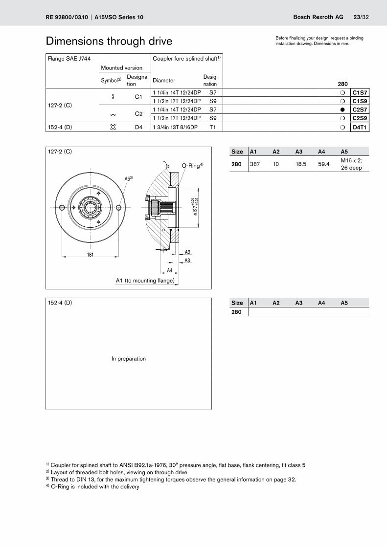
Dimensions through driveFlange SAE J744 Coupler fore splined shaft1)
Mounted version
Symbol2) Designa-tion
DiameterDesig-nation 280
127-2 (C)C1
1 1/4in 14T 12/24DP S7 m C1S71 1/2in 17T 12/24DP S9 m C1S9
C21 1/4in 14T 12/24DP S7 l C2S71 1/2in 17T 12/24DP S9 m C2S9
152-4 (D) D4 1 3/4in 13T 8/16DP T1 m D4T1
127-2 (C) Size A1 A2 A3 A4 A5
END STOP MIN. Anschlag min.
END STOP MAX. Anschlag max.
N 1 1/4 14T 12/24DP
M16
ID
ENTIF
ICAT
ION
PLAT
ETy
pens
child
RNM
1201
0-00
0
Ø127+
0.05
+0.02
DP
MA
M T2 S
A
162+0.2-0.2
45°
( ) 15 14263+0.5
-0.5
P
0
140
156.4
159.4
222.4
154.7
140
0
Ø74
1018.5
59.4
64.1 0
3 100
50062 5
181
121
150
ø127
+0.0
5+0
.02
181 A2A3
A4
A53)
280 387 10 18.5 59.4M16 x 2; 26 deep
152-4 (D) Size A1 A2 A3 A4 A5
In preparation
280
1) Coupler for splined shaft to ANSI B92.1a-1976, 30° pressure angle, flat base, flank centering, fit class 5 2) Layout of threaded bolt holes, viewing on through drive 3) Thread to DIN 13, for the maximum tightening torques observe the general information on page 32. 4) O-Ring is included with the delivery
A1 (to mounting flange)
O-Ring4)
Before finalizing your design, request a bindinginstallation drawing. Dimensions in mm.

24/32 Bosch Rexroth AG A15VSO Series 10 RE 92800/03.10
Dimensions through driveFlange SAE J744 Coupler for splined shaft1)
Mounted version
Symbol2) Designa-tion
DiameterDesig-nation 280
165-4 (E) E4 W60x2x28x9g A4 l E4A4
165-4 (E) Size A1 A2 A4 A5
ø165
+0.07
+0.0
2
224.
5
224.5 A2A4
A53) 280 417 17 68.1 M20; 30 deep
A1 (to mounting flange)
1) Coupler for splined shaft to ANSI B92.1a-1976, 30° pressure angle, flat base, flank centering, fit class 5 2) Layout of threaded boltholes, viewing on through drive 3) Thread to DIN 13, for the maximum tightening torques observe the general information on page 32. 4) O-Ring is included with the delivery
O-Ring4)
Before finalizing your design, request a bindinginstallation drawing. Dimensions in mm.

RE 92800/03.10 A15VSO Series 10 Bosch Rexroth AG 25/32
Dimensions through driveFlange ISO3019-2 Coupler for splined shaft1)
Mounted version
Symbol2) Designa-tion
Diameter Designa-tion
280
100-2 L5 1 in 15T 16/32DP S5 m L5S5
160-4 P4 1 1/4 in 14T 12/24DP S7 m P4S7
100-2 Size A1 A2 A3 A4 A5
In preparation
280
160-4 Size A1 A2 A3 A4 A5
In preparation
280
1) Coupler for splined shaft to ANSI B92.1a-1976, 30° pressure angle, flat base, flank centering, fit class 5 2) Layout of threaded bolt holes, viewing on through drive 3) Thread to DIN 13, for the maximum tightening torques observe the general information on page 32. 4) O-Ring is included with the delivery
Before finalizing your design, request a bindinginstallation drawing. Dimensions in mm.

26/32 Bosch Rexroth AG A15VSO Series 10 RE 92800/03.10
Dimensions through driveFlange ISO3019-2 Coupler for splined shaft1)
Mounted version
Symbol2) Designa-tion
DiameterDesigna-tion
280
180-4 R41 1/2 in 17T 12/24DP S9 m R4S91 3/4 in 13T 8/16 DP T1 m R4T1
180-4 Size A1 A2 A3 A4 A5
In preparation
280
1) Coupler for splined shaft to ANSI B92.1a-1976, 30° pressure angle, flat base, flank centering, fit class 5 2) Layout of threaded bolt hloles, viewing on through drive 3) Thread to DIN 13, for the maximum tightening torques observe the general information on page 32. 4) O-Ring is included with the delivery
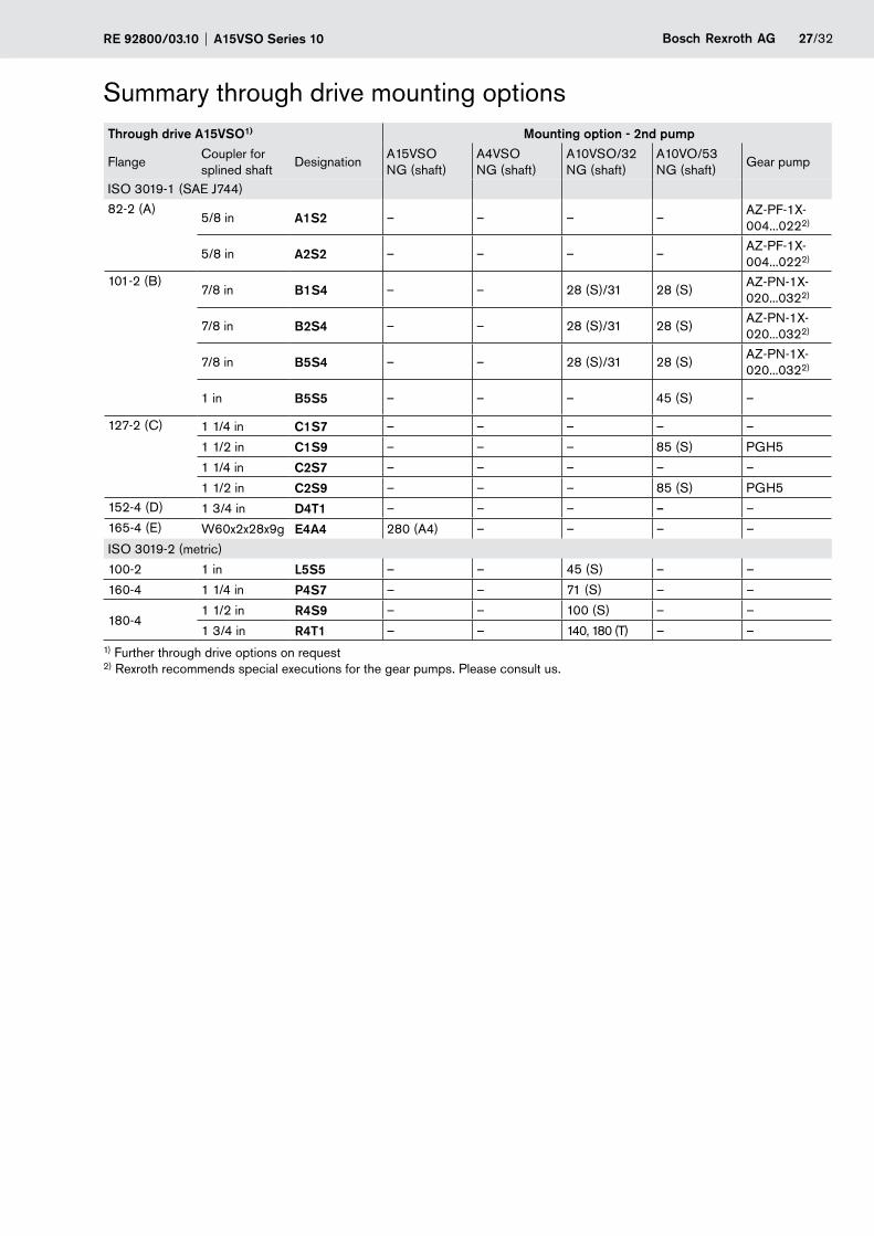
RE 92800/03.10 A15VSO Series 10 Bosch Rexroth AG 27/32
Summary through drive mounting optionsThrough drive A15VSO1) Mounting option - 2nd pump
FlangeCoupler for splined shaft
DesignationA15VSO NG (shaft)
A4VSO NG (shaft)
A10VSO/32 NG (shaft)
A10VO/53 NG (shaft)
Gear pump
ISO 3019-1 (SAE J744)
82-2 (A)5/8 in A1S2 – – – –
AZ-PF-1X- 004...0222)
5/8 in A2S2 – – – –AZ-PF-1X- 004...0222)
101-2 (B)7/8 in B1S4 – – 28 (S)/31 28 (S)
AZ-PN-1X- 020...0322)
7/8 in B2S4 – – 28 (S)/31 28 (S)AZ-PN-1X- 020...0322)
7/8 in B5S4 – – 28 (S)/31 28 (S)AZ-PN-1X- 020...0322)
1 in B5S5 – – – 45 (S) –
127-2 (C) 1 1/4 in C1S7 – – – – –
1 1/2 in C1S9 – – – 85 (S) PGH5
1 1/4 in C2S7 – – – – –
1 1/2 in C2S9 – – – 85 (S) PGH5152-4 (D) 1 3/4 in D4T1 – – – – –165-4 (E) W60x2x28x9g E4A4 280 (A4) – – – –
ISO 3019-2 (metric)
100-2 1 in L5S5 – – 45 (S) – –
160-4 1 1/4 in P4S7 – – 71 (S) – –
180-41 1/2 in R4S9 – – 100 (S) – –
1 3/4 in R4T1 – – 140, 180 (T) – –1) Further through drive options on request 2) Rexroth recommends special executions for the gear pumps. Please consult us.

28/32 Bosch Rexroth AG A15VSO Series 10 RE 92800/03.10
Combination pumps A15VSO + A15VSOOverall lenght A
A15VSO A15VSO (2. Pump)
(1. Pump) Size280
Size280 804
Independent circuits are available for the user when further pumps are built on, also without the need for splitter gear boxes.
When ordering combination pumps, the type designations of the first and of the second pump must be joined by a „+“ sign.
Ordering example: A15VSO280LRDRA0V/10MRVE4A41EE4A40-0+ A15VSO280LRDRA0V/10MRVE4A41EU0000-0
A tandem pump, consisting of two pumps of the same size can be operated with a dynamic load of up to max. 10 g (= 98.1 m/s2) without an additional support bracket.
For combination pumps, consisting of more than two pumps a calculation of the mounting flange strenght to determine the permissible mass moment of inertia is necessary.
A
A15VSO (1st pump)
A15VSO (2nd pump)
Before finalizing your design, request a bindinginstallation drawing. Dimensions in mm.
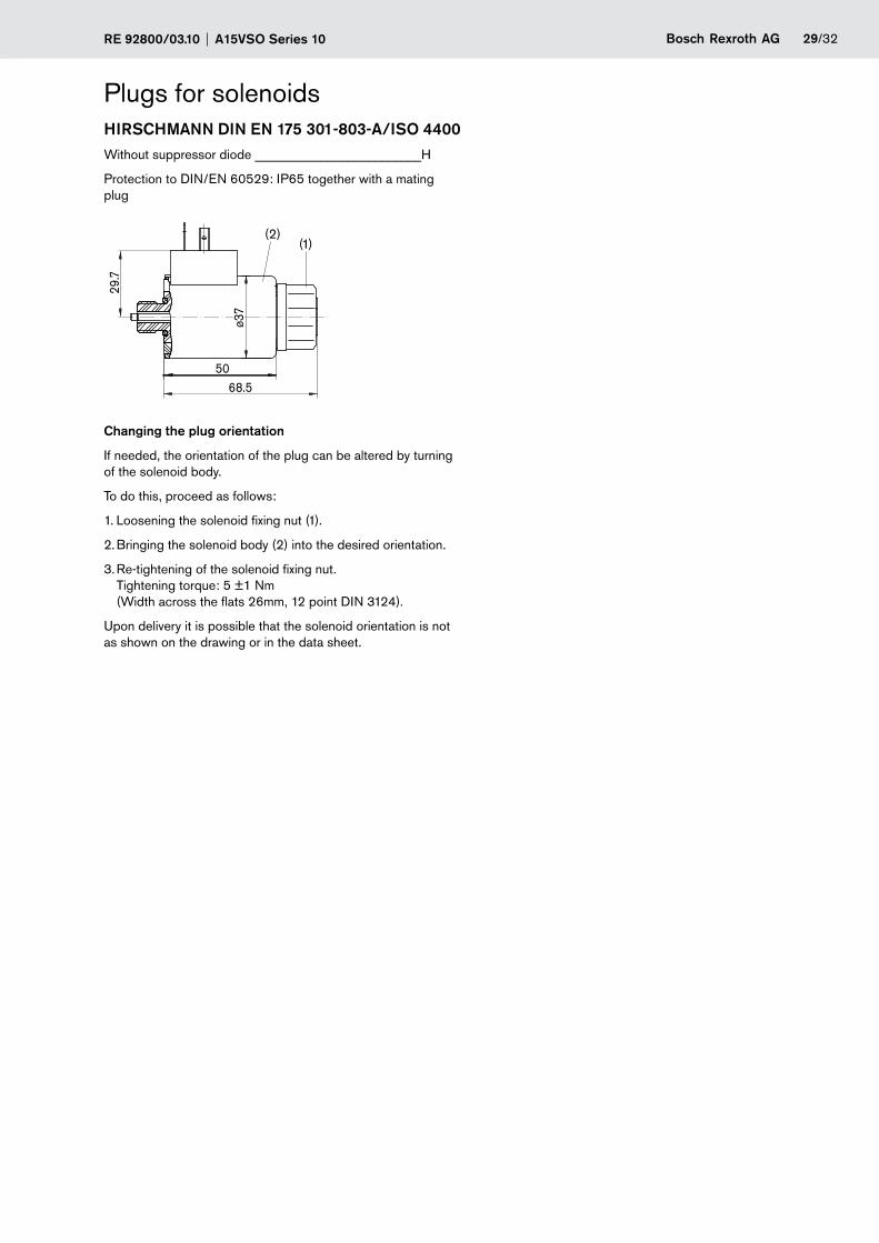
RE 92800/03.10 A15VSO Series 10 Bosch Rexroth AG 29/32
Plugs for solenoidsHIRSCHMANN DIN EN 175 301-803-A/ISO 4400Without suppressor diode _________________________H
Protection to DIN/EN 60529: IP65 together with a mating plug
68.5
ø37
50
29.7
(1)(2)
Changing the plug orientation
If needed, the orientation of the plug can be altered by turning of the solenoid body.
To do this, proceed as follows:
1. Loosening the solenoid fixing nut (1).
2. Bringing the solenoid body (2) into the desired orientation.
3. Re-tightening of the solenoid fixing nut. Tightening torque: 5 ±1 Nm (Width across the flats 26mm, 12 point DIN 3124).
Upon delivery it is possible that the solenoid orientation is not as shown on the drawing or in the data sheet.

30/32 Bosch Rexroth AG A15VSO Series 10 RE 92800/03.10
Installation notesGeneralThe axial piston unit must be filled with fluid and deaerated during commissioning and operation. This is also important after pro-longed periods of standstill, since the system can empty itself via the hydraulic lines (mounting above the reservoir).
The case drain fluid must be discharged to tank via the highest positioned one of the tank connections (T1, T2, T3). The minimum inlet pressure at suction port S may not fall below 0.8 bar absolute. (At cold start 0.5 bar absolute).
Under any operating conditions the suction and tank lines must enter the reservoir below the minimum fluid level.
Mounting position
See examples below. Further mounting positions are possible; please consult us.
Recommended mounting position: 1 and 2.
Mounting below the reservoir (Standard)
Pump below the minimum reservoir fluid level.
Mounting above the reservoir
Pump above the minimum reservoir fluid level. Observe the maximum permissible suction height hs max = 800 mm. Recommendation for mounting position 5 (drive shaft up-wards): A check valve in the case drain line to tank (cracking pressure 0.5 bar) can prevent the housing chamber from run-ning empty.
ht min200 mmhmin100 mm
T1T2
S
S
F F
ht min200 mmhmin100 mm
SB SB
amin amin
1 2
T2
T3
T1
ht min200 mmhmin100 mm
T2 S
F
SB
amin
3
T1
T3
T3
hS max800 mm
ht min200 mmhmin100 mm
hS max800 mm
SB ht min200 mmhmin100 mm
SB
FF
S
S
4 5
amin amin
T2
hS max800 mm
ht min200 mmhmin100 mm
SB
F
S
6
T1
amin
T1
T2
T3
T2
T3
T1
T3
0.5
bar
Mounting position Bleeding Filling Mounting position Bleeding Filling
1 T1 S + T1 (F) 4 F T1 (F)
2 T2 S + T2 (F) 5 F T2 (F)
3 T2 S + T2 (F) 6 F T2 (F)
hs max = 800 mm, ht min = 200 mm, hmin = 100 mm, SB = Baffle (wash plate)
Provide sufficient distance amin between the suction line and case drain line during design of the reservoir. This prevents a direct suction of heated case drain fluid.

RE 92800/03.10 A15VSO Series 10 Bosch Rexroth AG 31/32
Installation notesMounted inside the reservoir
Pump below minimum fluid level inside the reservoir.
Shmin100 mm
amin
ht min200 mm
87T2
hmin100 mm
ht min200 mm
amin
T1T1
T2
T3
T3
9
S
hmin100 mm
amin
ht min200 mm
T2
T1
T3
Mounted position
Bleeding Filling
7via the highest posi-tioned open port T1
automatically via the open port T1 , positioned below the fluid level
8via the highest posi-tioned open port T2
automatically via the open port T2, positioned below the fluid level
9via the highest posi-tioned open port T2
automatically via the open port T2, positioned below the fluid level
hs max = 800 mm, ht min = 200 mm, hmin = 100 mm, SB = Baffle (wash plate)
Provide sufficient distance amin between the suction line and the case drain line during the design of the reservoir. This pre-vents a direct suction of heated case drain fluid.

32/32 Bosch Rexroth AG A15VSO Series 10 RE 92800/03.10
© This document, as well as the data, specifications and other information set forth in it, are the exclusive property of Bosch Rexroth AG. It may not be repro-duced or given to third parties without its consent.
The data specified above only serve to describe the product. No statements concerning a certain condition or suitability for a certain application can be de-rived from our information. The information given does not release the user from the obligation of own judgment and verification. It must be remembered that our products are subject to a natural process of wear and aging.
Subject to change.
Bosch Rexroth AG HydraulicsAxial Piston UnitsAn den Kelterwiesen 1472160 Horb, GermanyTelefon +49 (0) 74 51 92-0Telefax +49 (0) 74 51 82 [email protected]/axial-piston-pumps
The pump A15VSO was designed for operation in open loop circuits. –
Systems design, installation and commissioning of the axial piston unit require trained technicians or tradesmen. –
Before operating the axial piston unit make sure to read the relevant operating manuel carefully and completely. If needed, –request this information from Rexroth.
All hydraulic ports can only be used for the fastening of hydraulic service lines. –
During and shortly after operation of a pump the housing and especially a solenoid can be extremely hot, avoid being burned; –take suitable safety measures (wear protective clothing).
Dependent on the operating conditions of the axial piston pump (operating pressure, fluid temperature) deviations in the perfor- –mance curves can occur.
Pressure ports: –All materials and port threads are selected and designed in such a manner, that they can withstand the peak pressures. The machine and system manufacturer must ensure, that all connecting elements and hydraulic lines are suitable for the actual operating conditions (pressures, flow, fluid, temperature) in accordance with the necessary safety factors.
All given data and information must be adhered to. –
The following tightening torques are valid: –
Female threads in the axial piston unit: -the maximum permissible tightening torques MG max are maximum values for the female threads in the pump casting and may not be exceeded. For values see table below.
Fittings: -please comply with the manufacturer‘s information regarding the max. permissible tightening torques for the used fittings.
Fastening bolts: -for fastening bolts to DIN 13 we recommend to check the permissible tightening torques in each individual case to VDI 2230.
Plugs: -for the metal plugs, supplied with the axial piston unit the following min. required tightening torques MV apply (see table)
The product has not been released as a component in the safety concept of a total machine system acc. to DIN EN ISO 13849. –
Ports Max. perm. tightening torque for female threadsMG max
Min. required tightening torque for plugs MV
Across the flats in socket of Allan head screwStandard Thread size
ISO 61491) M14 x 1.5 80 Nm 45 Nm 6 mm
M42 x 2 580 Nm 330 Nm 22 mm2)
1) The spot face can be deeper than specified in the appropriate standard. 2) Deviating from ISO 6149
General instructions