Axial piston variable pump A4VSO Series 10, 11 and 30
48
RE 92050-01-X-B2/2019-08-23, Bosch Rexroth AG Axial piston variable pump A4VSO Series 10, 11 and 30 for explosive areas II 2G Ex h IIC T4-T1 Gb X and II 3G Ex h IIC T4-T1 Gc X RE 92050-01-X-B2/2019-08-23 Replaces: 01.2017 Information on explosion protection ▶ Application per Directive 2014/34/EU (ATEX) ▶ Gas: II 2G Ex h IIC T4-T1 Gb X according to DIN EN ISO 80079-36 :2016, DIN EN ISO 80079-37 :2016 ▶ Gas: II 3G Ex h IIC T4-T1 Gc X according to DIN EN ISO 80079-36 :2016, DIN EN ISO 80079-37 :2016 Features Variable displacement pump with axial piston rotary group of swashplate design for hydrostatic drives in open circuit Flow is proportional to drive speed and displacement. Flow can be infinitely varied by controlling the swashplate angle. ▶ Excellent suction characteristics ▶ Low noise level ▶ Long service life ▶ Modular design ▶ Short control response times ▶ Variable through drive options ▶ Optical swivel angle indicator ▶ Sizes 40 to 500 ▶ Nominal pressure 350 bar ▶ Maximum pressure 400 bar ▶ Open circuit Contents Type code 2 Hydraulic fluids 4 Operating data monitoring – X parameters 5 Working pressure range 7 Technical data 8 Overview of control units 10 Dimensions, size 40 to 500 15 Dimensions, GE control, NG 71, 125 and 180 29 Dimensions, through drive 30 Overview of mounting options 41 Installation instructions 43 Project planning notes 45 Safety instructions 46 Part II of instruction manual in accordance with ATEX Directive 2014/34/EU data sheet
Transcript of Axial piston variable pump A4VSO Series 10, 11 and 30

RE 92050-01-X-B2/2019-08-23, Bosch Rexroth AG
Axial piston variable pumpA4VSO Series 10, 11 and 30for explosive areasII 2G Ex h IIC T4-T1 Gb X and II 3G Ex h IIC T4-T1 Gc X
RE 92050-01-X-B2/2019-08-23Replaces: 01.2017
Information on explosion protection ▶ Application per Directive 2014/34/EU (ATEX) ▶ Gas: II 2G Ex h IIC T4-T1 Gb X according to
DIN EN ISO 80079-36 :2016, DIN EN ISO 80079-37 :2016 ▶ Gas: II 3G Ex h IIC T4-T1 Gc X according to
DIN EN ISO 80079-36 :2016, DIN EN ISO 80079-37 :2016
FeaturesVariable displacement pump with axial piston rotary group of swashplate design for hydrostatic drives in open circuitFlow is proportional to drive speed and displacement.Flow can be infinitely varied by controlling the swashplate angle.
▶ Excellent suction characteristics ▶ Low noise level ▶ Long service life ▶ Modular design ▶ Short control response times ▶ Variable through drive options ▶ Optical swivel angle indicator
▶ Sizes 40 to 500 ▶ Nominal pressure 350 bar ▶ Maximum pressure 400 bar ▶ Open circuit
ContentsType code 2Hydraulic fluids 4Operating data monitoring – X parameters 5Working pressure range 7Technical data 8Overview of control units 10Dimensions, size 40 to 500 15Dimensions, GE control, NG 71, 125 and 180 29Dimensions, through drive 30Overview of mounting options 41Installation instructions 43Project planning notes 45Safety instructions 46
Part II of instruction manual in accordance with ATEX Directive 2014/34/EU data sheet

Bosch Rexroth AG, RE 92050-01-X-B2/2019-08-23
2 A4VSO Series 10, 11 and 30 | Axial piston variable pumpType code
Type code
01 02 03 04 05 06 07 08 09 10 11 12
A4VS O / – 25
Hydraulic fluid/type 40 71 125 180 250 355 500
01 Mineral oil (without code) ● ● ● ● ● ● ●
High-speed version – – – – ● ● ● H
Axial piston unit
02 Swashplate design, variable, nominal pressure 350 bar, maximum pressure 400 bar A4VS
Operating mode
03 Pump, open circuit O
Sizes (NG)
04 Geometric displacement, see table of values on page 6 40 71 125 180 250 355 500
Control devices Information on controller selection
05 Without control ● ● ● ● ● ● ● OV
Pressure controller See page 10 and data sheet 92060
● ● ● ● ● ● ● DR
Pressure controller for parallel operation ● ● ● ● ● ● ● DP
Flow controller ● ● ● ● ● ● ● FR..
Pressure and flow controller ● ● ● ● ● ● ● DFR.
Power controller with hyperbolic characteristic curve See page 12, 13 and data sheet 92064
● ● ● ● ● ● ● LR2..
Power controller with remotely controllable power characteristics
● ● ● ● ● ● ● LR3..
Manual control See page 14 Data sheet 92072
○ ○ ○ ○ ○ ○ ○ MA
Rod system control (maximum working pressure 150 bar) – ● ● ● – – – GE
Hydraulic control, pressure-dependentHD.U and HD.T not available in ATEX
See page 13 and data sheet 92080
● ● ● ● ● ● ● HD...
Series 40 71 125 180 250 355 500
06 Series 1, index 0 ● ● – – – – – 10
Series 1, index 1 only for HD control ● ● – – – – – 11
Series 3, index 0 – – ● ● ● ● ● 30
Directions of rotation 40 ... 500
07 Viewed on drive shaft clockwise ● R
counter-clockwise ● L
Seals and ATEX version 40 ... 500
08 FKM (fluoroelastomer) and ATEX version II 2G Ex h IIC T4-T1 Gb X ● R
FKM (fluoroelastomer) and ATEX version II 3G Ex h IIC T4-T1 Gc X ● A
Drive shafts 40 ... 500
09 Parallel keyed shaft DIN 6885 ● P
Splined shaft DIN 5480 ● Z
Mounting flange 40 71 125 180 250 355 500
10 In accordance with ISO 3019-2 (metric) 4-hole ● ● ● ● ● ● – B
8-hole – – – – – – ● H
Working port 40 ... 500
11 SAE flange ports, Fastening threadmetric
B and S offset 90° to the side 2. Pressure port B1 opposite B, plugged with flange plate on delivery
●25
● = Available ○ = On request – = Not available

RE 92050-01-X-B2/2019-08-23, Bosch Rexroth AG
3 Axial piston variable pump | A4VSO Series 10, 11 and 30 Type code
1) All attachment pumps must match the ATEX classification for the application in question.
2) With through-drive shaft, without hub, without intermediate flange, closed on a functionally reliable basis with cover.
3) Splined hub according to DIN 5480
4) Hub for splined shaft according to ANSI B92.1a, 30° pressure angle, flat root, side fit, tolerance class 5
5) See DIN EN ISO 80079-36, 6.4.2.1
Through drives1) (for mounting options, see page 41)
12 Flange ISO 3019-2 (metric) Hub for splined shaft For mounting of ATEX axial piston pumpDiameter Diameter 40 71 125 180 250 355 500
without through drive and auxiliary pump ● ● ● ● ● ● ● N00
with through drive for mounting of an axial piston pump ● ● – – – – ● K...
Universal through drive2) – – ● ● ● ● – U...
125-4 32x2x14x9g3) A4VS NG40 ● ● ● ● ● ● ● 31
140-4 40x2x18x9g3) A4VS NG71 – ● ● ● ● ● ● 33
160-4 50x2x24x9g3) A4VS NG125 and NG180 – – ● ● ● ● ● 34
224-4 60x2x28x9g3) A4VS NG250 – – – – ● ● ● 35
70x3x22x9g3) A4VS NG 355 and 500 – – – – – ● ● 77
315-8 80x3x25x9g3) A4VS NG 500 – – – – – – ● 43
80-2 3/4 in 11T 16/32DP4) A10VSO 18/31 ○ ● ● ● ● ● ○ B2
100-2 7/8 in 13T 16/32DP4) A10VSO 28/31 ● ● ● ● ● ● ○ B3
100-2 1 in 15T 16/32DP4) A10VSO 45/31 ● ● ● ● ● ● ● B4
125-2 1 1/4 in 14T 12/24DP4) A10VSO 71/31 – ● ● ● ● ● ● B5
125-2 1 1/2 in 17T 12/24DP4) A10VSO 100/31 – – ● ● ● ● ○ B6
Prepared for through drive, with pressure-resistant plugged cover ● ● ● ● ● ● ● 99
● = Available ○ = On request – = Not available
Notices ▶ Note the project planning notes on page 45. ▶ In addition to the type code, please specify the
relevant technical data when placing your order.
Features of the ATEX versionThe ATEX version is an advanced development of the A4VSO for compliance with Directive 2014/34/EU (ATEX). External features distinguishing it from the standard pump 92050 are the ground terminal, the Ex marking and the CE marking on the name plate.Temperature classes per DIN EN ISO 80079-36Depending on the two temperature classes, T3 and T4, observe the maximum permissible temperatures (see "Hydraulic fluid" and "Operating data monitoring – X parameters").
Notices ▶ ATEX classification: When ordering, please state
which equipment group, category, explosion group, temperature class and ignition protection type are required for your planned ATEX application.
▶ Technical data: Compared to the standard pump, restrictions apply in terms of temperature, case pressure and bearing flushing/installation position.
▶ Painting/color selection: In order to avoid mechanically generated sparks from contaminants made of aluminum with iron oxide and/or particles of rust of the surface5), the pump is painted as standard with corrosion protecting. Please contact your Rexroth partner for available colors.
▶ Bearing service life: The service life of the bearings must be calculated. The load cycle forms the basis for this. Please contact us.
▶ Potential equalization: The pump must be grounded. For grounding points, see drawings starting on page 15.
01 02 03 04 05 06 07 08 09 10 11 12
A4VS O / – 25

Bosch Rexroth AG, RE 92050-01-X-B2/2019-08-23
4 A4VSO Series 10, 11 and 30 | Axial piston variable pumpHydraulic fluids
Hydraulic fluids
The A4VSO ATEX variable pump is designed for operation with HLP mineral oil according to DIN 51524.See the following data sheets for application instructions and requirements for hydraulic fluids before the start of project planning:
▶ 90220: Hydraulic fluids based on mineral oils and related hydrocarbons
Information on the selection of hydraulic fluidSelection of hydraulic fluid shall make sure that the operating viscosity in the operating temperature range is within the optimum range (νopt; see selection diagram).Please noteThe leakage temperature which is influenced by pressure and rotational speed is always above the reservoir temperature.
Temperature class T4 and T3 as to ATEX:Safety instructions, see page 5
Ignition temperature of hydraulic fluidThe pump is approved for temperature class T4 to T1 according to DIN EN ISO 80079-36. Under DIN EN ISO 80079-37, only hydraulic fluids with an ignition temperature at least 50 K above the maximum surface temperature of the approved temperature class should be used. Example: For the temperature class T4, the ignition temperature of the hydraulic fluid should be ≥ 185 °C.
Viscosity and temperature of hydraulic fluids
Viscosity Temperature Comment
Cold start νmax ≤ 1000 mm2/s θSt ≥ -20 °C t ≤ 3 min, without load p ≤ 50 barMaximum permissible temperature difference between axial piston unit and hydraulic fluid in the system maximum 25 K
Warm-up phase ν = 1000 to 100 mm2/s θ ≥ -25 °C For pnom, 0.5 × nmax und t ≤ 15 min
Continuous operation ν = 100 to 16 mm2/s T3θ = -20 °C to +90 °CT4θ = -20 °C to +80 °C
Measured at the drain portObserve the permissible temperature range of the shaft seal
νopt = 36 to 16 mm2/s optimal operating viscosity and efficiency range
Short-term operation νmin ≤ 16 to 10 mm2/s θmax = +90 °C t < 3 min, p < 0.3 × pnom
▼ Selection diagram
-25 -10 10 30 50 8070 90010
4060
20
100
200
400600
1000
16
36
VG 22VG 32VG 46VG 68
VG 100
Optimum operating viscosity range vopt
Optimum efficiency
Maximum permissible viscosity on cold start
Minimum permissible viscosity for short-term operation
Temperature θ [°C]
Visc
osit
y v
[mm
2 /s]
Minimum permissible temperature on cold start

RE 92050-01-X-B2/2019-08-23, Bosch Rexroth AG
5 Axial piston variable pump | A4VSO Series 10, 11 and 30 Operating data monitoring – X parameters
Operating data monitoring – X parameters
Safety instructions for temperature class T3–T1ATEX category II 3G Ex h IIC T3–T1 Gc XTo observe the maximum leakage temperature of 90 °C, at least one of the following measures must be taken and checked regularly:
▶ Check the leakage temperature at port T or R(L) (maximum distance 30 cm)
▶ Check the maximum inlet temperature of 60 °C at the suction port
▶ Check a maximum inlet temperature that must be determined for the following operating points when commissioning: – Maximum working pressure and maximum
possible flow – Maximum working pressure and minimum flow
Also monitor the reservoir level. Take appropriate action if the temperature exceeds limits.
ATEX category II 2G Ex h IIC T3–T1 Gb XTo observe the maximum leakage temperature of 90 °C, the following measures must be taken:
▶ Continuously monitor leakage temperature at each pump with a temperature sensor on ports T or R(L) (maximum distance to port 30 cm).
▶ Connect the temperature sensor with a switching-off for the system at the limit temperature of 90 °C.
▶ This shut-off function should be tested during commissioning; see Chapter 8.1.1 of the instruction manual.
▶ Reservoir level monitoring is also required.
Safety instructions for temperature class T4ATEX category II 3G Ex h IIC T4 Gc XTo observe the maximum leakage temperature of 80 °C, at least one of the following measures must be taken and checked regularly:
▶ Check the leakage temperature at port T or R(L) (maximum distance 30 cm)
▶ Check the maximum inlet temperature of 50 °C at the suction port
▶ Check a maximum inlet temperature that must be determined for the following operating points when commissioning: – Maximum working pressure and maximum
possible flow – Maximum working pressure and minimum flow
Also monitor the reservoir level. Take appropriate action if the temperature exceeds limits.
ATEX category II 2G Ex h IIC T4 Gb XTo observe the maximum leakage temperature of 80 °C, the following measures must be taken:
▶ Continuously monitor leakage temperature at each pump with a temperature sensor on ports T or R(L) (maximum distance to port 30 cm).
▶ Connect the temperature sensor with a switching-off for the system at the limit temperature of 80 °C.
▶ This shut-off function should be tested during commissioning; see Chapter 8.1.1 of the instruction manual.
▶ Reservoir level monitoring is also required.
Bosch Rexroth AG, RE 92050-01-X-B2/2019-08-23
6 A4VSO Series 10, 11 and 30 | Axial piston variable pumpHydraulic fluids
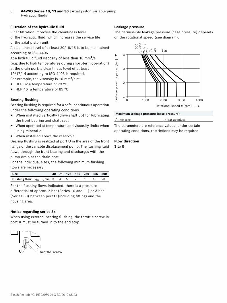
Filtration of the hydraulic fluidFiner filtration improves the cleanliness level of the hydraulic fluid, which increases the service life of the axial piston unit. A cleanliness level of at least 20/18/15 is to be maintained according to ISO 4406.At a hydraulic fluid viscosity of less than 10 mm²/s (e.g. due to high temperatures during short-term operation) at the drain port, a cleanliness level of at least 19/17/14 according to ISO 4406 is required.For example, the viscosity is 10 mm²/s at:
▶ HLP 32 a temperature of 73 °C ▶ HLP 46 a temperature of 85 °C
Bearing flushingBearing flushing is required for a safe, continuous operation under the following operating conditions:
▶ When installed vertically (drive shaft up) for lubricating the front bearing and shaft seal
▶ When operated at temperature and viscosity limits when using mineral oil
▶ When installed above the reservoirBearing flushing is realized at port U in the area of the front flange of the variable displacement pump. The flushing fluid flows through the front bearing and discharges with the pump drain at the drain port.For the individual sizes, the following minimum flushing flows are necessary:
Size 40 71 125 180 250 355 500
Flushing flow qsp l/min 3 4 5 7 10 15 20
For the flushing flows indicated, there is a pressure differential of approx. 2 bar (Series 10 and 11) or 3 bar (Series 30) between port U (including fitting) and the housing area.
Notice regarding series 3xWhen using external bearing flushing, the throttle screw in port U must be turned in to the end stop.
U Throttle screw
Leakage pressureThe permissible leakage pressure (case pressure) depends on the rotational speed (see diagram).
40003000200010000
4
3
2
1
180
125 71 40
500
250
355
Leak
age
pre
ssur
e pL
abs
. [bar
]
Size
Rotational speed n [rpm]
Maximum leakage pressure (case pressure)
pL abs max 4 bar absolute
The parameters are reference values; under certain operating conditions, restrictions may be required.
Flow directionS to B

RE 92050-01-X-B2/2019-08-23, Bosch Rexroth AG
7 Axial piston variable pump | A4VSO Series 10, 11 and 30 Working pressure range
Working pressure range
Pressure at working port B Definition
Nominal pressure pnom 350 bar abs. The nominal pressure corresponds to the maximum design pressure.
Maximum pressure pmax 400 bar abs. The maximum pressure corresponds to the maximum working pressure within a single operating period. The sum of the single operating periods must not exceed the total operating period (maximum number of cycles: approx. 1 million).
Single operating period 1 s
Total operating period 300 h
Minimum pressure (high-pressure side) 15 bar abs. Minimum pressure on the high-pressure side (B) which is required in order to prevent damage to the axial piston unit. The minimum pressure depends on the rotational speed and the swivel angle.
Rate of pressure change RA max 16000 bar/s Maximum permissible pressure build-up and reduction speed during a pressure change across the entire pressure range.
Pressure at suction port S (inlet)
Minimum pressure pS min Standard 0.8 bar abs. Minimum pressure at suction port S (inlet) which is required to prevent damage to the axial piston unit. The minimum pressure depends on the rotational speed and displacement of the axial piston unit.
Maximum pressure pS max 30 bar abs.
Case pressure at port T, K1, K2, R(L)
Maximum pressure pL max 4 bar abs. The permissible leakage pressure (case pressure) depends on the rotational speed. The parameters are reference values; under certain operating conditions, restrictions may be required.
Pressure peaks pL peak 6 bar abs. t < 0.1 s
▼ Rate of pressure change RA max
pnom
∆t
∆p
Time t
Pre
ssur
e p
▼ Minimum pressure (inlet) In order to avoid damage to the axial piston unit, a minimum pressure must be guaranteed at the suction port S (inlet).
1.0
0.9
1.0
0.8
0.5
n n nom
0.6 0.7 0.8 0.9 1.0Vg
Vg max
Rot
atio
nal
spee
d
Inle
t pre
ssur
e p
abs
[bar
]
Displacement
The inlet pressure is the static supply pressure and the minimum dynamic value, respectively, e.g. in case of pre-charge pressure.Maximum permissible rotational speed nnom, see page 8.
▼ Pressure definition
Pre
ssur
e p
t1
t2tnSingle operating period
Minimum pressure (high-pressure side)
Maximum pressure pmax
Nominal pressure pnom
Time t
Total operating period = t1 + t2 + ... + tn
NoticeWorking pressure range applies when using mineral oil-based hydraulic fluids. Please contact us for values for other hydraulic fluids.

Bosch Rexroth AG, RE 92050-01-X-B2/2019-08-23
8 A4VSO Series 10, 11 and 30 | Axial piston variable pumpTechnical data
Technical data
Size NG 40 71 125 180 250 250 H1) 355 355 H1) 500 500 H1)
Displacement geometric, per revolution
Vg max cm3 40 71 125 180 250 250 355 355 500 500
Rotational speed maximum2)
at Vg max nnom rpm 2600 2200 1800 1800 1500 1800 1500 1700 1320 1500
Flow at nnom and Vg max qv max l/min 104 156 225 324 375 450 533 604 660 750
at nE = 1500 rpm qvE max l/min 60 107 186 270 375 375 533 533 – 750
Power with nnom, Vg max and Δp = 350 bar
P kW 61 91 131 189 219 262 311 352 385 437
at nE = 1500 rpm, Vg max and Δp = 350 bar
PE max kW 35 62 109 158 219 219 311 311 – 437
Torque at Vg max and Δp = 350 bar
Tmax Nm 223 395 696 1002 1391 1391 1976 1976 2783 2783
at Vg max and Δp = 100 bar
T Nm 64 113 199 286 398 398 564 564 795 795
Rotary stiffness Drive shaft
P c kNm/rad 80 146 260 328 527 527 800 800 1145 1145
Z c kNm/rad 77 146 263 332 543 543 770 770 1136 1136
Moment of inertia of the rotary group JTW kgm2 0.0049 0.0121 0.03 0.055 0.0959 0.0959 0.19 0.19 0.3325 0.3325
Maximum angular acceleration3) α rad/s² 17000 11000 8000 6800 4800 4800 3600 3600 2800 2800
Case volume V L 2 2.5 5 4 10 10 8 8 14 14
Weight without through drive (approx.)
m kg 39 53 88 102 184 184 207 207 320 320
Determining the operating characteristics
Flow qv =Vg • n • ηv
[l/min]1000
Torque T = Vg • Δp
[Nm]20 • π • ηmh
Power P =2 π • T • n
=qv • Δp
[kW]60000 600 • ηt
Key
Vg = Displacement per revolution [cm3]
Δp = Differential pressure [bar]
n = Rotational speed [rpm]
ηv = Volumetric efficiency
ηmh = Mechanical-hydraulic efficiency
ηt = Total efficiency (ηt = ηv • ηmh)
Notice ▶ Theoretical values, without efficiency and tolerances;
values rounded ▶ Exceeding the maximum or falling below the minimum
permissible values can lead to a loss of function, a reduction in operational service life or total destruction of the axial piston unit and loss of explosion protection. We recommend testing the loads by means of experiment or calculation / simulation and comparison with the permissible values.
1) High-speed version2) The values are applicable:
– at an abs. pressure pabs = 1 bar at the suction port S ‒ for the optimum viscosity range from νopt = 36 to 16 mm2/s ‒ with hydraulic fluid on the basis of mineral oils
3) The data are valid for values between the minimum required and maximum permissible rotational speed. It applies for external stimuli (e.g. diesel engine 2 to 8 times rotary frequency, cardan shaft twice the rotary frequency). The limit value is only valid for a single pump. The load capacity of the connection parts must be considered.

RE 92050-01-X-B2/2019-08-23, Bosch Rexroth AG
9 Axial piston variable pump | A4VSO Series 10, 11 and 30 Technical data
Permissible radial and axial loading of the drive shaft
Size NG 40 71 125 180 250 355 500
Maximum radial force at a/2 ± Fq max N 1000 1200 1600 2000 2000 2200 2500
Maximum axial forceFax ±
+ Fax max N 600 800 1000 1400 1800 2000 2000
Notice ▶ The values given are maximum values and do not apply
to continuous operation. For drives with radial loading (pinion, V-belt drives), please contact us!
Permissible drive and through-drive torquesThe axial piston unit can be delivered with a through drive, as shown in the type code on page 2.The through drive version is identified by the code K/U 31...35.
Size 40 71 125 180 250 355 500
Splined shaft
Maximum permissible overall drive torque on shaft of pump 1
(pump 1 + pump 2) Ttot max Nm 446 790 1392 2004 2782 3952 5566
A Permissible through-drive torqueTD1 max Nm 223 395 696 1002 1391 1976 2783
TD2 max Nm 223 395 696 1002 1391 1976 2783
B Permissible through-drive torqueTD1 max Nm 223 395 696 1002 1391 1976 2783
TD2 max Nm 223 395 696 1002 1391 1976 2783
Shaft key
Maximum permissible overall drive torque on shaft of pump 1
(pump 1 + pump 2) Ttot max Nm 380 700 1392 1400 2300 3557 5200
A Permissible through-drive torqueTD1 max Nm 223 395 696 1002 1391 1976 2783
TD2 max Nm 157 305 696 398 909 1581 2417
B Permissible through-drive torqueTD1 max Nm 157 305 696 398 909 1581 2417
TD2 max Nm 223 395 696 1002 1391 1976 2783
Distribution of torques
TGes
TD1 TD2
A
TD1 TD2
TGesB
Single pump with through driveIf no further pumps are to be mounted at the factory, then the simple type designation is sufficient.The scope of delivery includes:
▶ For all through drives: coupling, fixing screw, seal and if applicable an intermediate flange
It is advisable to couple no more than three single pumps in series.All attachment pumps must match the ATEX classification for the application in question.
Combination pumpsIndependent circuits are available for the user when further pumps are built on.If the combination pump comprises 2 Rexroth axial piston pumps and if this is supplied pre-assembled, the two type designations are to be linked with "+".Order example:A4VSO125DR/30R–APB25U33 + A4VSO71DR/10R–AZB25N00
Fq
a
a/2 a/2

Bosch Rexroth AG, RE 92050-01-X-B2/2019-08-23
10 A4VSO Series 10, 11 and 30 | Axial piston variable pumpOverview of control units
Overview of control units
OV - Without control ▼ Circuit diagram
At axial piston units without OV control, the stroking piston is based on DR control. The stroking piston is relieved to the tank. The Vg max limitation can be adjusted from 50 to 100%. The axial piston unit without control acts like a fixed pump in operation.
R(L)TK2K1
B1 MBB
M2M1U MSS
DR – Pressure controller (see 92060)
▼ Circuit diagram
The DR pressure controller limits the maximum pressure at the pump outlet within the control range of the pump. This maximum pressure level can be steplessly set at the control valve.
▶ Setting range 20...350 barOptional:Remotely controllable (DRG)
▼ Characteristic curve
qv min qv max
p
B1 MBB
U MSS R(L)TK2K1
RE 92050-01-X-B2/2019-08-23, Bosch Rexroth AG
11 Axial piston variable pump | A4VSO Series 10, 11 and 30 DP – Pressure controller for parallel operation (see 92060)
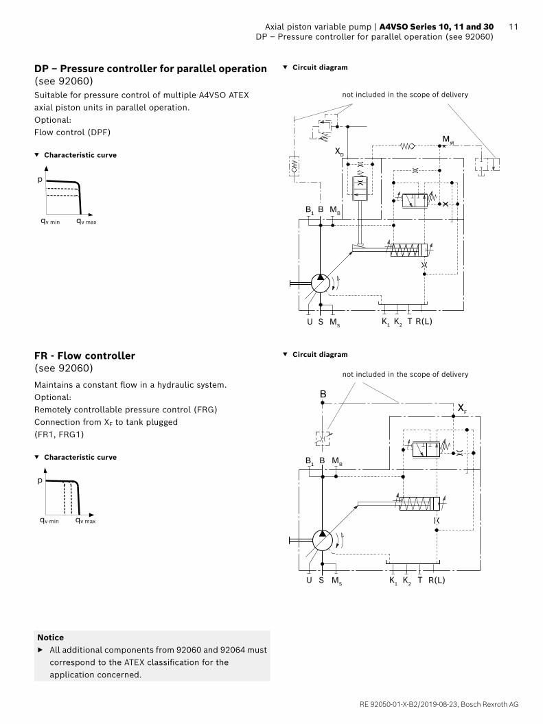
DP – Pressure controller for parallel operation (see 92060)
▼ Circuit diagram
Suitable for pressure control of multiple A4VSO ATEX axial piston units in parallel operation.Optional:Flow control (DPF)
▼ Characteristic curve
p
qv min qv max
Mst
XD
B1 MBB
U MSS R(L)TK2K1
not included in the scope of delivery
FR - Flow controller (see 92060)
▼ Circuit diagram
Maintains a constant flow in a hydraulic system.Optional:Remotely controllable pressure control (FRG)Connection from XF to tank plugged(FR1, FRG1)
▼ Characteristic curve
p
qv min qv max
XF
B
B1 MBB
U MSS R(L)TK2K1
Notice ▶ All additional components from 92060 and 92064 must
correspond to the ATEX classification for the application concerned.
not included in the scope of delivery

Bosch Rexroth AG, RE 92050-01-X-B2/2019-08-23
12 A4VSO Series 10, 11 and 30 | Axial piston variable pumpDFR - Pressure and flow controller (see 92060)
DFR - Pressure and flow controller (see 92060)
▼ Circuit diagram
This controller keeps the flow of the pump constant even under changing operating conditions.The flow control is overlaid by a mechanically adjustable pressure controller.Optional:Connection from XF to the tank plugged (DFR1)
▼ Characteristic curve
p
qv min qv max
R(L)TU S MS K1 K2
BB1 MB
XF
Bnot included in the scope of delivery
LR2 - Power controller with hyperbolic characteristic curve (see 92064)
▼ Circuit diagram
The hyperbolic power controller keeps the specified drive power constant at the same drive speed.Optional:Pressure control (LR2D), remotely controllable (LR2G);Flow control (LR2F, LR2S);
Hydraulic two-point control (LR2Z)Not available from RE 92064:LR2.Y (electric relief valve)
▼ Characteristic curve
Vg min Vg max
p
R(L)TU S MS K1 K2
MBBB1
RKV
Notice ▶ All additional components from 92060 and 92064 must
correspond to the ATEX classification for the application concerned.

RE 92050-01-X-B2/2019-08-23, Bosch Rexroth AG
13 Axial piston variable pump | A4VSO Series 10, 11 and 30 LR3 - Power control with remotely controllable power characteristic (see 92064)
LR3 - Power control with remotely controllable power characteristic (see 92064)
▼ Circuit diagram
This hyperbolic power controller keeps the specified drive power constant, whereby the power characteristic is adjustable remotely.Optional:Pressure control (LR3D), remotely controllable (LR3G);Flow control (LR3F, LR3S); hydraulic two-point control (LR3Z)Not available from RE 92064:LR3.Y (electric relief valve)
▼ Characteristic curve
Vg min Vg max
p
R(L)TU S MS K1 K2
MBBB1
RKVXLR
HD – Hydraulic control, pilot-pressure related (see 92080)
▼ Circuit diagram
Stepless adjustment of the pump displacement according to the pilot pressure.The control is proportional to the specified pilot pressure (difference between pilot pressure and case pressure).Optional:Control characteristics (HD1, HD2, HD3); pressure control (HD.B); Remote pressure control (HD.GB); power control (HD1P)Not available from RE92080:HD..T and HD..U (DBEP6 mounted)
▼ Characteristic curve
Vg
Vg max
pSt
P
U R(L)TK1 K2MSS
BB1 MB
X2
Notice ▶ All additional components from 92060 and 92064 must
correspond to the ATEX classification for the application concerned.

Bosch Rexroth AG, RE 92050-01-X-B2/2019-08-23
14 A4VSO Series 10, 11 and 30 | Axial piston variable pumpMA – Manual control (see 92072)
MA – Manual control (see 92072)
Manual control enables adjustment of the pump displacement by rotating the handwheel.The change of displacement can be monitored via the swivel angle indicator.The MA adjustment has a locking lever for fixing the displacement during operation.
▼ Circuit diagram (example using A4VSO)
1
2
R(L)TU S MS K2 K3
B MBB1
Components1 Axial Piston variable Pump A4VSO2 Handwheel
GE – Rod system control
A stroke movement of the stroking piston is realized by means of directly connected control on the customer site with a direct connection to the rod system of the stroking piston. This leads to a change in displacement of the pump from Vg min to Vg max or vice versa.The change of displacement can be monitored via the optical swivel angle indicator.
Maximum control force NG 71: 6000 N
Maximum control force NG 125, 180: 9000 N
Maximum permissible working pressure: 150 bar
Flow direction
Drive direction viewed on drive shaft
Swivel direction Flow
clockwise counter-clockwise B, B1
Circuit diagram (example using A4VSO NG71)
1
R(L)TU S MS K2 K3
B MBB1
Components1 Axial Piston variable Pump A4VSO

RE 92050-01-X-B2/2019-08-23, Bosch Rexroth AG
15 Axial piston variable pump | A4VSO Series 10, 11 and 30 Dimensions, size 40
Dimensions, size 40
DR – Pressure control; flange valve version metric (for further dimensions of control units, please refer to the respective data sheets)
XT MB MS
S
B
K2 K1
U
B1
B
R(L)
Y
Y
B S
R(L) R(L)
91
90528
140
266227
80
18
(260)
150
85ø1
5
150
ø160
147
30144 25
8030
79
80
ø125
h8
23.8
50.8
ø20.
5
35.7
69.9
ø40
45° 45°
135
15
15
0
LR
Flange 125, 4-hole according to ISO 3019-2
Ground terminal1)
Control valve mounting for clockwise rotation
Control valve mounting for counter-clockwise rotation
2. High-pressure port
B1, illustrated without flange plate
1) Ground terminal configured for up to 2×4 mm2. Minimum cross section for ground wire 2.5 mm2
▼ View Y ▼ View X

Bosch Rexroth AG, RE 92050-01-X-B2/2019-08-23
16 A4VSO Series 10, 11 and 30 | Axial piston variable pumpDimensions, size 40
Dimensions [mm]
▼ Cyl. shaft with shaft key (DIN 6885) ▼ Splined shaft (DIN 5480)
P ‒ AS10 × 8 × 56 Z ‒ W32 × 2 × 14 × 9g
1.5
22
58
56
68
ø32
M10
1)2)
3)
35-0
.2
+0.0
18+0
.002
Shaft key width 10
M10
x 1
.51)
2)
46
7.522
36
28
ø40
Ports Standard Size3) pmax abs [bar]4) State9)
B Working port (high-pressure series)Fastening thread
SAE J5186)
DIN 133/4 inM10 × 1.5; 17 deep
400 O
B1 2. Working port (high-pressure series)Fastening thread
SAE J5186)
DIN 133/4 inM10 × 1.5; 17 deep
400 X8)
S Suction portFastening thread
SAE J5186)
DIN 131 1/2 inM12 × 1.75; 20 deep
30 O
K1, K2 Flushing port DIN 38525) M22 × 1.5; 14 deep 2 X
T Fluid drain DIN 38525) M22 × 1.5; 14 deep 2 X
MB Measuring pressure B DIN 38525) M14 × 1.5; 12 deep 400 X
MS Measuring pressure S DIN 38525) M14 × 1.5; 12 deep 30 X
R(L) Fluid filling and air bleeding(drain port)
DIN 38525) M22 × 1.5; 12 deep 2 O
U Flushing port DIN 38525) M14 × 1.5; 11.5 deep 5 X7)
1) Center bore according to DIN 3322) Thread according to DIN 133) Observe the instructions in Part I (product-specific and general
instructions) concerning the maximum tightening torques.4) Depending on the application, momentary pressure peaks can occur.
Keep this in mind when selecting measuring devices and fittings.5) The countersink may be deeper than specified in the standard.6) Metric fastening thread is a deviation from standard.
7) For above-reservoir installation and for all installation positions with "drive shaft up" a bearing flushing must be installed.
8) Plugged and high-pressure-proof with flange plate. Depending on application, B and/or B1 must be connected. The unused port must be plugged with a flange plate.
9) O = Must be connected (comes plugged) X = Plugged (in normal operation)

RE 92050-01-X-B2/2019-08-23, Bosch Rexroth AG
17 Axial piston variable pump | A4VSO Series 10, 11 and 30 Dimensions, size 71Dimensions [mm]
Dimensions, size 71
DR – Pressure control; flange valve version metric (for further dimensions of control units, please refer to the respective data sheets)
Y
U
R(L)
B1
B
Y
K2 K1
MB MSSX
B
SB
T
R(L) R(L)
ø140
h8
27
92
166 27
92.5
3492
.5
(298)
170
97ø1
5
170
ø180
157
18
106
101618
295254
92.5
42.9
77.8
ø50
27.8
57.2
ø25
152
15
15
0LR
45° 45°
Flange 140, 4-hole according to ISO 3019-2
Ground terminal1)
Control valve mounting for clockwise rotation
Control valve mounting for counter-clockwise rotation
2. High-pressure port
B1, illustrated without flange plate
1) Ground terminal configured for up to 2×4 mm2. Minimum cross section for ground wire 2.5 mm2
▼ View Y ▼ View X

Bosch Rexroth AG, RE 92050-01-X-B2/2019-08-23
18 A4VSO Series 10, 11 and 30 | Axial piston variable pumpDimensions, size 71
Dimensions [mm]
▼ Parallel keyed shaft DIN 6885 ▼ Splined shaft DIN 5480
P ‒ Ø40 AS 12×8×68 Z ‒ W40×2×18×9g
1.5
28
70
68
80
ø40
M12
1)2)
3)
43-0
.2
+0.0
02+0
.018
Shaft key width 12
55
28
46
M12
1)2)
3)
Ports Standard Size3) pmax abs [bar]4) State9)
B Working port (high-pressure series)Fastening thread
SAE J5186)
DIN 131 inM12 × 1.75; 20 deep
400 O
B1 2. Working port (high-pressure series)Fastening thread
SAE J5186)
DIN 131 inM12 × 1.75; 20 deep
400 X8)
S Suction port SAE J5186)
DIN 132 inM12 × 1.75; 20 deep
30 O
K1, K2 Flushing port DIN 38525) M27 × 2; 16 deep 2 X
T Fluid drain DIN 38525) M27 × 2; 16 deep 2 X
MB Measuring pressure B DIN 38525) M14 × 1.5; 12 deep 400 X
MS Measuring pressure S DIN 38525) M14 × 1.5; 12 deep 30 X
R(L) Fluid filling and air bleeding(drain port)
DIN 38525) M27 × 2; 16 deep 2 O
U Flushing port DIN 38525) M14 × 1.5; 12 deep 5 X7)
1) Center bore according to DIN 3322) Thread according to DIN 133) Observe the instructions in Part I (product-specific and general
instructions) concerning the maximum tightening torques.4) Depending on the application, momentary pressure peaks can occur.
Keep this in mind when selecting measuring devices and fittings.5) The countersink may be deeper than specified in the standard.6) Metric fastening thread is a deviation from standard.
7) For above-reservoir installation and for all installation positions with "drive shaft up" a bearing flushing must be installed.
8) Plugged and high-pressure-proof with flange plate. Depending on application, B and/or B1 must be connected. The unused port must be plugged with a flange plate.
9) O = Must be connected (comes plugged) X = Plugged (in normal operation)

RE 92050-01-X-B2/2019-08-23, Bosch Rexroth AG
19 Axial piston variable pump | A4VSO Series 10, 11 and 30 Dimensions, size 125Dimensions [mm]
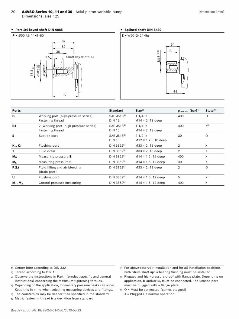
Dimensions, size 125
DR – Pressure control; flange valve version metric (for further dimensions of control units, please refer to the respective data sheets)
B
31.8
66.7
ø31
M2 B1
M1
BU
T MB MS
S
K2 K1
R(L) R(L)
X
Y
Y
R(L)
B
355
191
310
112.
5
22
121
8125
7050
112.
511
2.5
33
112
14 14
ø160
h8
ø63
88.9
50.8
S
(354)
ø200
114.
520
0
200
ø20
186
203
15
15
0LR
45° 45°
Flange 160, 4-hole according to ISO 3019-2
Ground terminal1)
Control valve mounting for clockwise rotation
Control valve mounting for counter-clockwise rotation
2. High-pressure port
B1, illustrated without flange plate
1) Ground terminal configured for up to 2×4 mm2. Minimum cross section for ground wire 2.5 mm2
▼ View Y ▼ View X
Location R(L) for HD control
Bosch Rexroth AG, RE 92050-01-X-B2/2019-08-23
20 A4VSO Series 10, 11 and 30 | Axial piston variable pumpDimensions, size 125
Dimensions [mm]
▼ Parallel keyed shaft DIN 6885 ▼ Splined shaft DIN 5480
P ‒ Ø50 AS 14×9×80 Z ‒ W50×2×24×9g
1.5
36
82
80
92
ø50
M16
1)2)
3)
53.5
-0.2
+0.0
02+0
.018
Shaft key width 14
64
36
54
M16
1)2)
3)
Ports Standard Size3) pmax abs [bar]4) State9)
B Working port (high-pressure series)Fastening thread
SAE J5186)
DIN 131 1/4 inM14 × 2; 19 deep
400 O
B1 2. Working port (high-pressure series)Fastening thread
SAE J5186)
DIN 131 1/4 inM14 × 2; 19 deep
400 X8)
S Suction port SAE J5186)
DIN 132 1/2 inM12 × 1.75; 18 deep
30 O
K1, K2 Flushing port DIN 38525) M33 × 2; 18 deep 2 X
T Fluid drain DIN 38525) M33 × 2; 18 deep 2 X
MB Measuring pressure B DIN 38525) M14 × 1.5; 12 deep 400 X
MS Measuring pressure S DIN 38525) M14 × 1.5; 12 deep 30 X
R(L) Fluid filling and air bleeding(drain port)
DIN 38525) M33 × 2; 18 deep 2 O
U Flushing port DIN 38525) M14 × 1.5; 12 deep 5 X7)
M1, M2 Control pressure measuring DIN 38525) M14 × 1.5; 12 deep 400 X
1) Center bore according to DIN 3322) Thread according to DIN 133) Observe the instructions in Part I (product-specific and general
instructions) concerning the maximum tightening torques.4) Depending on the application, momentary pressure peaks can occur.
Keep this in mind when selecting measuring devices and fittings.5) The countersink may be deeper than specified in the standard.6) Metric fastening thread is a deviation from standard.
7) For above-reservoir installation and for all installation positions with "drive shaft up" a bearing flushing must be installed.
8) Plugged and high-pressure-proof with flange plate. Depending on application, B and/or B1 must be connected. The unused port must be plugged with a flange plate.
9) O = Must be connected (comes plugged) X = Plugged (in normal operation)

RE 92050-01-X-B2/2019-08-23, Bosch Rexroth AG
21 Axial piston variable pump | A4VSO Series 10, 11 and 30 Dimensions, size 180Dimensions [mm]
Dimensions, size 180
DR – Pressure control; flange valve version metric (for further dimensions of control units, please refer to the respective data sheets)
BUM1
M2 B1
K2 K1
MBSMST
B
R(L)
R(L)
R(L)
X
Y
Y
B
(354)
114.
520
0
200
ø20
ø200
22
375
116
318
121
191
8125
70
112 ø1
60h8
3314 14
120
120
50
66.7
ø31
ø75
106.
4
61.9
S
186
203
31.8
15
15
0LR
45° 45°
Flange 160, 4-hole according to ISO 3019-2
Ground terminal1)
Control valve mounting for clockwise rotation
Control valve mounting for counter-clockwise rotation
2. High-pressure port
B1, illustrated without flange plate
1) Ground terminal configured for up to 2×4 mm2. Minimum cross section for ground wire 2.5 mm2
▼ View Y ▼ View X
Location R(L) for HD control

Bosch Rexroth AG, RE 92050-01-X-B2/2019-08-23
22 A4VSO Series 10, 11 and 30 | Axial piston variable pumpDimensions, size 180
Dimensions [mm]
▼ Parallel keyed shaft DIN 6885 ▼ Splined shaft DIN 5480
P ‒ Ø50 AS 14×9×80 Z ‒ W50×2×24×9g
1.5
36
82
80
92
ø50
M16
1)2)
3)
53.5
-0.2
0.00
20.
018
Shaft key width 14
64
36
54
M16
1)2)
3)
Ports Standard Size3) pmax abs [bar]4) State9)
B Working port (high-pressure series)Fastening thread
SAE J5186)
DIN 131 1/4 inM14 × 2; 19 deep
400 O
B1 2. Working port (high-pressure series)Fastening thread
SAE J5186)
DIN 131 1/4 inM14 × 2; 19 deep
400 X8)
S Suction port SAE J5186)
DIN 133 inM16 × 2; 24 deep
30 O
K1, K2 Flushing port DIN 38525) M33 × 2; 18 deep 2 X
T Fluid drain DIN 38525) M33 × 2; 18 deep 2 X
MB Measuring pressure B DIN 38525) M14 × 1.5; 12 deep 400 X
MS Measuring pressure S DIN 38525) M14 × 1.5; 12 deep 30 X
R(L) Fluid filling and air bleeding(drain port)
DIN 38525) M33 × 2; 18 deep 2 O
U Flushing port DIN 38525) M14 × 1.5; 12 deep 5 X7)
M1, M2 Control pressure measuring DIN 38525) M14 × 1.5; 12 deep 400 X
1) Center bore according to DIN 3322) Thread according to DIN 133) Observe the instructions in Part I (product-specific and
general instructions) concerning the maximum tightening torques.4) Depending on the application, momentary pressure peaks can occur.
Keep this in mind when selecting measuring devices and fittings.5) The countersink may be deeper than specified in the standard.6) Metric fastening thread is a deviation from standard.
7) For above-reservoir installation and for all installation positions with "drive shaft up" a bearing flushing must be installed.
8) Plugged and high-pressure-proof with flange plate. Depending on application, B and/or B1 must be connected. The unused port must be plugged with a flange plate.
9) O = Must be connected (comes plugged) X = Plugged (in normal operation)

RE 92050-01-X-B2/2019-08-23, Bosch Rexroth AG
23 Axial piston variable pump | A4VSO Series 10, 11 and 30 Dimensions, size 250Dimensions [mm]
Dimensions, size 250
DR – Pressure control; flange valve version metric (for further dimensions of control units, please refer to the respective data sheets)
K2 K1
T MB MSS
U M1 B
B1M2
B S
R(L)
B
R(L) R(L)
X
Y
Y
380
144
435
30
153
1508 90
ø280
265
145
265
ø24
(426)
43
144
17
5514
4
248
ø224
h8
79.4
36.5
ø40
ø75
106.
4
61.9
144
233
17
238
15
15
0LR
45° 45°
Flange 224, 4-hole according to ISO 3019-2
Ground terminal1)
Control valve mounting for clockwise rotation
Control valve mounting for counter-clockwise rotation
2. High-pressure port
B1, illustrated without flange plate
1) Ground terminal configured for up to 2×4 mm2. Minimum cross section for ground wire 2.5 mm2
▼ View Y ▼ View X
Location R(L) for HD control

Bosch Rexroth AG, RE 92050-01-X-B2/2019-08-23
24 A4VSO Series 10, 11 and 30 | Axial piston variable pumpDimensions, size 250
Dimensions [mm]
▼ Parallel keyed shaft DIN 6885 ▼ Splined shaft DIN 5480
P ‒ Ø60 AS 18×11×100 Z ‒ W60×2×28×9g
3
42
105
100
115
ø60
M20
1)2)
3)
64-0
.2
0.01
10.
030
Shaft key width 18
80
42
70
M20
1)2)
3)
Ports Standard Size3) pmax abs [bar]4) State9)
B Working port (high-pressure series)Fastening thread
SAE J5186)
DIN 131 1/2 inM16 × 2; 25 deep
400 O
B1 2. Working port (high-pressure series)Fastening thread
SAE J5186)
DIN 131 1/2 inM16 × 2; 25 deep
400 X8)
S Suction port SAE J5186)
DIN 133 inM16 × 2; 24 deep
30 O
K1, K2 Flushing port DIN 38525) M42 × 2; 20 deep 2 X
T Fluid drain DIN 38525) M42 × 2; 20 deep 2 X
MB Measuring pressure B DIN 38525) M14 × 1.5; 12 deep 400 X
MS Measuring pressure S DIN 38525) M14 × 1.5; 12 deep 30 X
R(L) Fluid filling and air bleeding(drain port)
DIN 38525) M42 × 2; 20 deep 2 O
U Flushing port DIN 38525) M14 × 1.5; 12 deep 5 X7)
M1, M2 Control pressure measuring DIN 38525) M14 × 1.5; 12 deep 400 X
1) Center bore according to DIN 3322) Thread according to DIN 133) Observe the instructions in Part I (product-specific and general
instructions) concerning the maximum tightening torques.4) Depending on the application, momentary pressure peaks can occur.
Keep this in mind when selecting measuring devices and fittings.5) The countersink may be deeper than specified in the standard.6) Metric fastening thread is a deviation from standard.
7) For above-reservoir installation and for all installation positions with "drive shaft up" a bearing flushing must be installed.
8) Plugged and high-pressure-proof with flange plate. Depending on application, B and/or B1 must be connected. The unused port must be plugged with a flange plate.
9) O = Must be connected (comes plugged) X = Plugged (in normal operation)

RE 92050-01-X-B2/2019-08-23, Bosch Rexroth AG
25 Axial piston variable pump | A4VSO Series 10, 11 and 30 Dimensions, size 355Dimensions [mm]
Dimensions, size 355
DR – Pressure control; flange valve version metric (for further dimensions of control units, please refer to the respective data sheets)
K1K2
T MBMS S
M2
B1
BM1U
S
R(L)
X
Y
Y
R(L)
R(L)
B (B1)
238
1717
5514
814
8
(424)
393464
248
ø224
-0.0
72
265
144.
526
5
ø24
30
153
1508 90
40
144
144
ø100
130.
2
77.8
233
ø280
45° 45°
79.4
36.5
ø40
15
15
0LR
B
Flange 224, 4-hole according to ISO 3019-2
Ground terminal1)
Control valve mounting for clockwise rotation
Control valve mounting for counter-clockwise rotation
2. High-pressure port
B1, illustrated without flange plate
1) Ground terminal configured for up to 2×4 mm2. Minimum cross section for ground wire 2.5 mm2
▼ View Y ▼ View X
Location R(L) for HD control

Bosch Rexroth AG, RE 92050-01-X-B2/2019-08-23
26 A4VSO Series 10, 11 and 30 | Axial piston variable pumpDimensions, size 355
Dimensions [mm]
▼ Parallel keyed shaft DIN 6885 ▼ Splined shaft DIN 5480
P ‒ Ø70 AS 20×12×100 Z ‒ W70×3×22×9g
4.5
42
105
100
115
ø70
M20
1)2)
3)
74.5
-0.2
+0.0
18+0
.002
Shaft key width 20
M20
x 2
.51)
2)3
)
92
1542
82
ø72
69
Ports Standard Size3) pmax abs [bar]4) State9)
B Working port (high-pressure series)Fastening thread
SAE J5186)
DIN 131 1/2 inM16 × 2; 25 deep
400 O
B1 2. Working port (high-pressure series)Fastening thread
SAE J5186)
DIN 131 1/2 inM16 × 2; 25 deep
400 X8)
S Suction port SAE J5186)
DIN 134 inM16 × 2; 24 deep
30 O
K1, K2 Flushing port DIN 38525) M42 × 2; 20 deep 2 X
T Fluid drain DIN 38525) M42 × 2; 20 deep 2 X
MB Measuring pressure B DIN 38525) M14 × 1.5; 12 deep 400 X
MS Measuring pressure S DIN 38525) M14 × 1.5; 12 deep 30 X
R(L) Fluid filling and air bleeding(drain port)
DIN 38525) M42 × 2; 20 deep 2 O
U Flushing port DIN 38525) M18 × 1.5; 12 deep 5 X7)
M1, M2 Control pressure measuring DIN 38525) M18 × 1.5; 12 deep 400 X
1) Center bore according to DIN 3322) Thread according to DIN 133) Observe the instructions in Part I (product-specific and general
instructions) concerning the maximum tightening torques.4) Depending on the application, momentary pressure peaks can occur.
Keep this in mind when selecting measuring devices and fittings.5) The countersink may be deeper than specified in the standard.6) Metric fastening thread is a deviation from standard.
7) For above-reservoir installation and for all installation positions with "drive shaft up" a bearing flushing must be installed.
8) Plugged and high-pressure-proof with flange plate. Depending on application, B and/or B1 must be connected. The unused port must be plugged with a flange plate.
9) O = Must be connected (comes plugged) X = Plugged (in normal operation)

RE 92050-01-X-B2/2019-08-23, Bosch Rexroth AG
27 Axial piston variable pump | A4VSO Series 10, 11 and 30 Dimensions, size 500Dimensions [mm]
Dimensions, size 500
DR – Pressure control; flange valve version metric (for further dimensions of control units, please refer to the respective data sheets)
ø24
M2B1
M1 B
K1K2
MSMB ST
S
X
Y
Y
B (B1)
R(L) R(L)
R(L)
520441
16+5
11
4780
155
283
(510)
ø405
190
ø360
190 190
8x45° 45°
22°
180
30'
(=360°)
158
158
50
27930
ø228
ø315
-0.0
81
ø230
+5
50
ø125
152.
4
92.1
ø50
96.8
44.5
19028
0
189
U16
15
15
0LR
B
Flange 315, 8-hole according to ISO 3019-2
Ground terminal1)
Control valve mounting for clockwise rotation
Control valve mounting for counter-clockwise rotation
2. High-pressure port
B1, illustrated without flange plate
1) Ground terminal configured for up to 2×4 mm2. Minimum cross section for ground wire 2.5 mm2
▼ View Y ▼ View X
Transport thread for eye bolt M16 × 2; 27 deep DIN 580

Bosch Rexroth AG, RE 92050-01-X-B2/2019-08-23
28 A4VSO Series 10, 11 and 30 | Axial piston variable pumpDimensions, size 500
Dimensions [mm]
▼ Parallel keyed shaft DIN 6885 ▼ Splined shaft DIN 5480
P ‒ Ø80 AS 22×14×125 Z ‒ W80×3×25×9g
3
42
130
125
180
ø80
M20
1)2)
3)
85-0
.2
+0.0
18+0
.002
Shaft key width 22
140
42
90
M20
1)2)
3)
Ports Standard Size3) pmax abs [bar]4) State9)
B Working port (high-pressure series)Fastening thread
SAE J5186)
DIN 132 inM20 × 2; 25 deep
400 O
B1 2. Working port (high-pressure series)Fastening thread
SAE J5186)
DIN 132 inM20 × 2; 25 deep
400 X8)
S Suction port SAE J5186)
DIN 135 inM16 × 2.5; 24 deep
30 O
K1, K2 Flushing port DIN 38525) M48 × 2; 22 deep 2 X
T Fluid drain DIN 38525) M48 × 2; 22 deep 2 X
MB Measuring pressure B DIN 38525) M18 × 1.5; 12 deep 400 X
MS Measuring pressure S DIN 38525) M18 × 1.5; 12 deep 30 X
R(L) Fluid filling and air bleeding(drain port)
DIN 38525) M48 × 2; 22 deep 2 O
U Flushing port DIN 38525) M18 × 1.5; 12 deep 5 X7)
M1, M2 Control pressure measuring DIN 38525) see data sheet of control units
400 X
1) Center bore according to DIN 3322) Thread according to DIN 133) Observe the instructions in Part I (product-specific and general
instructions) concerning the maximum tightening torques.4) Depending on the application, momentary pressure peaks can occur.
Keep this in mind when selecting measuring devices and fittings.5) The countersink may be deeper than specified in the standard.6) Metric fastening thread is a deviation from standard.
7) For above-reservoir installation and for all installation positions with "drive shaft up" a bearing flushing must be installed.
8) Plugged and high-pressure-proof with flange plate. Depending on application, B and/or B1 must be connected. The unused port must be plugged with a flange plate.
9) O = Must be connected (comes plugged) X = Plugged (in normal operation)

RE 92050-01-X-B2/2019-08-23, Bosch Rexroth AG
29 Axial piston variable pump | A4VSO Series 10, 11 and 30 Dimensions, GE control, NG 71, 125 and 180Dimensions [mm]
Dimensions, GE control, NG 71, 125 and 180
GE – Rod system control (clockwise rotation, counter-clockwise swivel direction)
L
R(L)
M2
B
B1
M1
15°
15°
0
D5
D2
0
M14
x 1
.5
D3
D1 D4
20
Control stroke up to Vg max (at Vg min)
Further dimensions and ports in respective sizes can be found in this manual.
Size D1 D2 D3 D4 D5 Ports M1 and M2 State
71 180 17.1 108 149 166 – –
125 178 20.7 132 177 203 M14 × 1.5 plugged
180 178 20.7 132 177 203 M14 × 1.5 plugged

Bosch Rexroth AG, RE 92050-01-X-B2/2019-08-23
30 A4VSO Series 10, 11 and 30 | Axial piston variable pumpDimensions, through drive
Dimensions [mm]
Dimensions, through drive
Flange ISO 3019-2 (metric) Hub for splined shaft2) Availability across sizes Code
Diameter Symbol Diameter 40 71 125 180 250 355 500
125-4 N32×2×14×8H ● ● – – – – ● K31N32×2×14×8H – – ● ● ● ● – U31
● = Available ○ = On request ‒ = Not available
▼ 125-4 ▼ 125-4
A1 (to mounting flange)
Section M-N
N
M
ø160
ø125
+0.0
7+0
.02
1)
45º
A6
A7
A4
A5
A3 A2
A1 (to mounting flange)
Section M-N
N
M
ø160
45º
A7
ø125
+0.0
5+0
.02
A4
A3
1)
A2
K31 NG A1 A2 A3 A4 A5 A6 A73) U31 NG A1 A2 A3 A4 A73)
40 288 12.5 40 9 – – M12; 24 deep 125 369 12.5 35.6 9 M12; 22 deep
71 316 12.5 33.6 9 – – M12; 24 deep 180 393 12.5 35.6 9 M12; 22 deep
500 505 12.5 38.5 9 15 240 M12; 18 deep 250 453 12.5 38.0 9 M12; 15 deep
355 482 12.5 38.0 9 M12; 15 deep
NoticeAll attachment pumps must match the ATEX classification for the application in question.
1) Mounting bolts and O-ring seal are included in the scope of delivery
2) Splined hub according to DIN 54803) Thread according to DIN 13, see Part I for maximum tightening
torques.

RE 92050-01-X-B2/2019-08-23, Bosch Rexroth AG
31 Axial piston variable pump | A4VSO Series 10, 11 and 30 Dimensions, through driveDimensions [mm]
Flange ISO 3019-2 (metric) Hub for splined shaft2) Code
Diameter Symbol Diameter 40 71 125 180 250 355 500
140-4 N40×2×18×8H – ● – – – – ● K33N40×2×18×8H – – ● ● ● ● – U33
● = Available ○ = On request ‒ = Not available
▼ 140-4 ▼ 140-4
A1 (to mounting flange)
Section M-N
N
M
ø180ø1
40 +0
.07
+0.0
2
1)
45º
A6
A7
A4
A5
A3 A2
A1 (to mounting flange)
Section M-N
N
M
ø180
45º
A7
ø140
+0.0
5+0
.02
A4
A3
1)
A2
K33 NG A1 A2 A3 A4 A5 A6 A73) U33 NG A1 A2 A3 A4 A73)
71 316 11.5 42.8 9 – – M12; 24 deep 125 369 12.5 43.8 9 M12; 22 deep
500 505 12.5 57 9 – – M12; 18 deep 180 393 12.5 43.8 9 M12; 22 deep
250 453 12.5 48.9 9 M12; 22 deep
355 482 12.5 48.0 9 M12; 22 deep
NoticeAll attachment pumps must match the ATEX classification for the application in question.
1) Mounting bolts and O-ring seal are included in the scope of delivery
2) Splined hub according to DIN 54803) Thread according to DIN 13, see Part I for maximum tightening
torques.

Bosch Rexroth AG, RE 92050-01-X-B2/2019-08-23
32 A4VSO Series 10, 11 and 30 | Axial piston variable pumpDimensions, through drive
Dimensions [mm]
Flange ISO 3019-2 (metric) Hub for splined shaft2) Code
Diameter Symbol Diameter 40 71 125 180 250 355 500
160-4 N50×2×24×8H – – – – – – ● K34N50×2×24×8H – – ● ● ● ● – U34
● = Available ○ = On request ‒ = Not available
▼ 160-4
A1 (to mounting flange)
Section M-N
ø160
+0.0
7+0
.02
N
MA7
ø200
45º
1)
A4
A3 A2
A1 (to mounting flange)
Section M-N
N
M
45º
A7
ø160
+0.0
5+0
.02
A4
A3
1)
A2
ø200
K34 NG A1 A2 A3 A4 A73) U34 NG A1 A2 A3 A4 A73)
500 505 13.5 54.6 10 M16; 24 deep 125 369 12.5 51.6 9 M16; 22 deep
180 393 12.5 51.6 9 M16; 22 deep
250 453 12.5 54.0 9 M16; 22 deep
355 482 12.5 54.0 9 M15; 22 deep
NoticeAll attachment pumps must match the ATEX classification for the application in question.
1) Mounting bolts and O-ring seal are included in the scope of delivery
2) Splined hub according to DIN 54803) Thread according to DIN 13, see Part I for maximum tightening
torques.
RE 92050-01-X-B2/2019-08-23, Bosch Rexroth AG
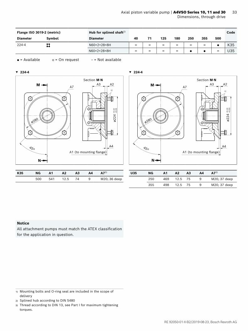
33 Axial piston variable pump | A4VSO Series 10, 11 and 30 Dimensions, through drive
Flange ISO 3019-2 (metric) Hub for splined shaft2) Code
Diameter Symbol Diameter 40 71 125 180 250 355 500
224-4 N60×2×28×8H – – – – – – ● K35N60×2×28×8H – – – – ● ● – U35
● = Available ○ = On request ‒ = Not available
▼ 224-4 ▼ 224-4
A1 (to mounting flange)
Section M-N
N
M
ø224
+0.1
0+0
.03
1)
45º
A7
A4
A3 A2
ø280
A1 (to mounting flange)
Section M-N
N
M
ø224
+0.1
0+0
.03
1)
45º
A7
A4
A3 A2
ø280
K35 NG A1 A2 A3 A4 A73) U35 NG A1 A2 A3 A4 A73)
500 541 12.5 74 9 M20; 36 deep 250 469 12.5 75 9 M20; 37 deep
355 498 12.5 75 9 M20; 37 deep
NoticeAll attachment pumps must match the ATEX classification for the application in question.
1) Mounting bolts and O-ring seal are included in the scope of delivery
2) Splined hub according to DIN 54803) Thread according to DIN 13, see Part I for maximum tightening
torques.

Bosch Rexroth AG, RE 92050-01-X-B2/2019-08-23
34 A4VSO Series 10, 11 and 30 | Axial piston variable pumpDimensions, through drive
Flange ISO 3019-2 (metric) Hub for splined shaft2) Code
Diameter Symbol Diameter 40 71 125 180 250 355 500
224-4 N70×3×22×8H – – – – – – ● K77N70×3×22×8H – – – – – ● – U77
● = Available ○ = On request ‒ = Not available
▼ 224-4 ▼ 224-4
A1 (to mounting flange)
Section M-N
N
M
ø224
+0.1
0+0
.03
1)
45º
A7
A4
A3 A2
ø280
A1 (to mounting flange)
Section M-N
N
M
ø224
+0.
10+0
.03
1)
45º
A7
A4
A3 A2
ø280
K77 NG A1 A2 A3 A4 A73) U77 NG A1 A2 A3 A4 A73)
500 541 12.5 82 9 M20; 36 deep 355 498 12.5 75 9 M20; 37 deep
NoticeAll attachment pumps must match the ATEX classification for the application in question.
1) Mounting bolts and O-ring seal are included in the scope of delivery
2) Splined hub according to DIN 54803) Thread according to DIN 13, see Part I for maximum tightening
torques.

RE 92050-01-X-B2/2019-08-23, Bosch Rexroth AG
35 Axial piston variable pump | A4VSO Series 10, 11 and 30 Dimensions, through drive
Flange ISO 3019-2 (metric) Hub for splined shaft2) Code
Diameter Symbol Diameter 40 71 125 180 250 355 500
315-8 N80×3×25×8H – – – – – – ● K43
● = Available ○ = On request ‒ = Not available
▼ 315-8
22º30´
8×45º
(=360º)
N
M
ø315
+0.
10+0
.03
1)
45º
A7
A4
A3 A2
ø360
A1 (to mounting flange)
Section M-N
K43 NG A1 A2 A3 A4 A73)
500 590 53.5 71.9 19 M20; 26 deep
NoticeAll attachment pumps must match the ATEX classification for the application in question.
1) Mounting bolts and O-ring seal are included in the scope of delivery
2) Splined hub according to DIN 54803) Thread according to DIN 13, see Part I for maximum tightening
torques.

Bosch Rexroth AG, RE 92050-01-X-B2/2019-08-23
36 A4VSO Series 10, 11 and 30 | Axial piston variable pumpDimensions, through drive
Dimensions [mm]
Flange ISO 3019-2 (metric) Hub for splined shaft2) Code
Diameter Symbol Diameter 40 71 125 180 250 355 500
80-2 3/4 in 11T 16/32DP ○ ● – – – – ○ KB2
, , , 3/4 in 11T 16/32DP – – ● ● ● ● – UB2
● = Available ○ = On request ‒ = Not available
▼ 80-2 ▼ 80-2
N
M
ø80 +
0.05
+0.0
21)
45ºA5
A4
A3 A2A8
A7
ø109
A1 (to mounting flange)
Section M-N
A1 (to mounting flange)
Section M-N
N
M
ø80 +
0.05
+0.0
2
1)
45º A4
A3A2
A8
A7
ø109
KB2 NG A1 A2 A3 A4 A5 A7 A83) UB2 NG A1 A2 A3 A4 A73) A83)
71 291 21.5 19 10 2 140 M10; 15 deep 125 367 40.5 19.4 9 180 M10; 16 deep
180 393 40.5 19.4 9 180 M10; 16 deep
250 453 40.5 19 9 200 M10; 16 deep
355 482 40.4 19 9 200 M10; 16 deep
NoticeAll attachment pumps must match the ATEX classification for the application in question.
1) Mounting bolts and O-ring seal are included in the scope of delivery
2) Involute spline according to ANSI B92.1a, 30° pressure angle, flat root, side fit, tolerance class 5
3) Thread according to DIN 13, see Part I for maximum tightening torques.

RE 92050-01-X-B2/2019-08-23, Bosch Rexroth AG
37 Axial piston variable pump | A4VSO Series 10, 11 and 30 Dimensions, through driveDimensions [mm]
Flange ISO 3019-2 (metric) Hub for splined shaft2) Code
Diameter Symbol Diameter 40 71 125 180 250 355 500
100-2 7/8 in 13T 16/32DP ● ● – – – – ○ KB3
, , , 7/8 in 13T 16/32DP – – ● ● ● ● – UB3
● = Available ○ = On request ‒ = Not available
▼ 100-2 ▼ 100-2
A1 (to mounting flange)
Section M-N
N
M
ø100
+0.
05+0
.02
1)
45ºA5
A4
A3 A2
A8
A7
ø140
M
A1 (to mounting flange)
Section M-N
N
M
ø100
+0.
05+0
.02
1)
45º A4
A2A3
A7
ø140
KB3 NG A1 A2 A3 A4 A5 A73) A8 UB3 NG A1 A2 A3 A4 A73)
40 290 20.3 23 10 ‒ – M12; 18 deep 125 369 20.5 24.9 10 M12; 22 deep
71 291 20.4 23 10 2 140 M12; 18 deep 180 393 20.5 24.9 10 M12; 22 deep
250 453 19.5 23 10 M12; 18 deep
355 482 19.5 23 10 M12; 18 deep
NoticeAll attachment pumps must match the ATEX classification for the application in question.
1) Mounting bolts and O-ring seal are included in the scope of delivery
2) Involute spline according to ANSI B92.1a, 30° pressure angle, flat root, side fit, tolerance class 5
3) Thread according to DIN 13, see Part I for maximum tightening torques.

Bosch Rexroth AG, RE 92050-01-X-B2/2019-08-23
38 A4VSO Series 10, 11 and 30 | Axial piston variable pumpDimensions, through drive
Dimensions [mm]
Flange ISO 3019-2 (metric) Hub for splined shaft2) Code
Diameter Symbol Diameter 40 71 125 180 250 355 500
100-2 1 in 15T 16/32DP ● ● – – – – ● KB4
, , , 1 in 15T 16/32DP – – ● ● ● ● – UB4
● = Available ○ = On request ‒ = Not available
▼ 100-2 ▼ 100-2
A1 (to mounting flange)
Section M-N
A7
N
ø100
+0.
05+0
.02
1)
45º
A5
A3 A2
A8
ø140
M
A4
A1 (to mounting flange)
Section M-N
N
M
ø100
+0.
05+0
.02
1)
45º A4
A2A3
A7
ø140
KB4 NG A1 A2 A3 A4 A5 A73) A8 UB4 NG A1 A2 A3 A4 A73)
40 290 20.8 27.5 10 ‒ ‒ M12; 18 deep 125 369 18.9 29.5 10 M12; 22 deep
71 316 20.8 27.5 8 ‒ ‒ M12; 24 deep 180 393 18.9 29.5 10 M12; 22 deep
500 505 20.4 28.9 10 15 240 M12; 18 deep 250 453 20.9 29.5 10 M12; 18 deep
355 482 20.9 29.5 10 M12; 18 deep
NoticeAll attachment pumps must match the ATEX classification for the application in question.
1) Mounting bolts and O-ring seal are included in the scope of delivery
2) Involute spline according to ANSI B92.1a, 30° pressure angle, flat root, side fit, tolerance class 5
3) Thread according to DIN 13, see Part I for maximum tightening torques.

RE 92050-01-X-B2/2019-08-23, Bosch Rexroth AG
39 Axial piston variable pump | A4VSO Series 10, 11 and 30 Dimensions, through driveDimensions [mm]
Flange ISO 3019-2 (metric) Hub for splined shaft2) Code
Diameter Symbol Diameter 40 71 125 180 250 355 500
125-2 1 1/4 in 14T 12/24DP – ● – – – – ● KB5, 1 1/4 in 14T 12/24DP – – ● ● ● ● – UB5
● = Available ○ = On request ‒ = Not available
▼ 125-2 ▼ 125-2
A1 (to mounting flange)
Section M-N
N
1)
45º
A7 A3 A2
ø180
M
A4
ø125
+0.
05+0
.02
A1 (to mounting flange)
Section M-N
N
1)
45º
A7A3 A2
ø180
M
A4
ø125
+0.
05+0
.02
KB5 NG A1 A2 A3 A4 A73) UB5 NG A1 A2 A3 A4 A73)
71 321 23 38 10 M16; 29 deep 125 369 20 38 9 M16; 22 deep
500 505 19.3 40.4 10 M16; 20 deep 180 393 20 38 9 M16; 22 deep
250 453 20.9 37.9 9 M16; 22 deep
355 482 20.9 37.9 9 M16; 22 deep
NoticeAll attachment pumps must match the ATEX classification for the application in question.
1) Mounting bolts and O-ring seal are included in the scope of delivery
2) Involute spline according to ANSI B92.1a, 30° pressure angle, flat root, side fit, tolerance class 5
3) Thread according to DIN 13, see Part I for maximum tightening torques.
Bosch Rexroth AG, RE 92050-01-X-B2/2019-08-23
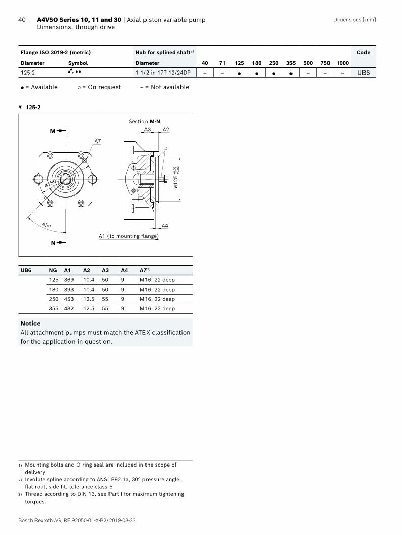
40 A4VSO Series 10, 11 and 30 | Axial piston variable pumpDimensions, through drive
Dimensions [mm]
Flange ISO 3019-2 (metric) Hub for splined shaft2) Code
Diameter Symbol Diameter 40 71 125 180 250 355 500 750 1000
125-2 , 1 1/2 in 17T 12/24DP – – ● ● ● ● – – – UB6
● = Available ○ = On request ‒ = Not available
▼ 125-2
A1 (to mounting flange)
Section M-N
N
1)
45º
A7
A3 A2M
A4
ø125
+0.
05+0
.02
ø180
UB6 NG A1 A2 A3 A4 A73)
125 369 10.4 50 9 M16; 22 deep
180 393 10.4 50 9 M16; 22 deep
250 453 12.5 55 9 M16; 22 deep
355 482 12.5 55 9 M16; 22 deep
NoticeAll attachment pumps must match the ATEX classification for the application in question.
1) Mounting bolts and O-ring seal are included in the scope of delivery
2) Involute spline according to ANSI B92.1a, 30° pressure angle, flat root, side fit, tolerance class 5
3) Thread according to DIN 13, see Part I for maximum tightening torques.

RE 92050-01-X-B2/2019-08-23, Bosch Rexroth AG
41 Axial piston variable pump | A4VSO Series 10, 11 and 30 Overview of mounting optionsDimensions [mm]
Overview of mounting options
Through drive Mounting options – 2nd Pump
Flange ISO 3019-2 Hub for splined shaft Short designation A4VSO ATEXNG (shaft)
125–4 N32×2×14×9g K31; U31 40 (Z)
140–4 N40×2×18×9g K33; U33 71 (Z)
160–4 N50×2×24×9g U34 125, 180 (Z)
224–4 N60×2×28×9g U35 250 (Z)
N70×3×22×8H K77; U77 355 (Z)
315-8 N80×3×25×8H K43 500 (Z)
Flange ISO 3019-2 Hub for splined shaft Short designation A10VSO ATEXNG (shaft)
80-2 3/4 in 11T 16/32DP KB2; UB2 18 (S, R)
100-2 7/8 in 13T 16/32DP KB3; UB3 28 (S, R)
1 in 15T 16/32DP KB4; UB4 45 (S, R)
125-2 1 1/4 in 14T 12/24DP KB5; UB5 71 (S, R)
1 1/2 in 17T 12/24DP KB6; UB6 100 (S)
Combination pumps A4VSO + A4VSO (A4VSO + A10VSO)
A tandem pump, with two pumps of equal size, is permissible without additional supports, assuming that the dynamic mass acceleration does not exceed maximum 10 g (= 98.1 m/s2). For combination pumps consisting of more than two pumps, the mounting flange must be rated for the permissible mass torque (please contact us).
NoticeAll attachment pumps must match the ATEX classification for the application in question.
Permissible mass moment of inertia A4VSO
NG 40 71 125 180 250 355 500
static Tm Nm 1800 2000 4200 4200 9300 9300 15600
dynamic at 10 g (98.1 m/s2) Tm Nm 180 200 420 420 930 930 1560
Weight m kg 39 53 88 102 184 207 320
Distance from center of gravity l1 mm 120 140 170 180 210 220 230
Permissible mass moment of inertia A10VSO
NG 18 28 45 71 100
static Tm Nm 500 880 1370 2160 3000
dynamic at 10 g (98.1 m/s2) Tm Nm 50 88 137 216 300
Weight with through-drive plate m kg 14 19 25 39 54
Weight without through-drive plate 12 15 21 33 45
Distance from center of gravity l1 mm 90 110 130 150 160
l2
l1
m1 m2
m1, m2 Weight of pump [kg]
l1, l2 Distance from center of gravity
[mm]
Tm = (m1 × l1 + m2 • l2 ) ×1
[Nm]102

Bosch Rexroth AG, RE 92050-01-X-B2/2019-08-23
42 A4VSO Series 10, 11 and 30 | Axial piston variable pumpDimensions of combination pumps made up of two A4VSO ATEX
Dimensions [mm]
Dimensions of combination pumps made up of two A4VSO ATEX
Total length "A" with attachment pump A4VSO
Pump 1 sizes Pump 2 sizes
40 71 125 180 250 355 500
40 554 – – – – – –
71 582 611 – – – – –
125 635 664 724 – – – –
180 659 688 748 768 – – –
250 719 748 808 828 904 – –
355 748 777 837 857 933 962 –
500 771 800 860 880 976 1005 1110
Total length "A" with attachment pump A10VSOPump 1 sizes Pump 2 sizes
18 28 45 71 100
40 458 496 514 – –
71 486 497 540 548 –
125 564 575 593 626 698
180 588 599 617 650 722
250 648 659 677 710 782
355 677 688 706 741 811
500 700 711 729 764 857
AA
1st pump
2nd pump
NoticeAll attachment pumps must match the ATEX classification for the application in question.

RE 92050-01-X-B2/2019-08-23, Bosch Rexroth AG
43 Axial piston variable pump | A4VSO Series 10, 11 and 30 Installation instructions
Installation instructions
GeneralThe axial piston unit must be filled with hydraulic fluid and air bled during commissioning and operation. This must also be observed following a longer standstill as the axial piston unit may empty via the hydraulic lines.Particularly in the installation position "drive shaft upwards", filling and air bleeding must be carried out completely as there is, for example, a danger of dry running.The leakage in the housing area must be directed to the reservoir via the highest drain port (T, K1, K2, R(T)).For combination pumps, the leakage must be drained off at each single pump.If a shared drain line is used for several units, make sure that the respective case pressure in each unit is not exceeded. The shared drain line must be dimensioned to ensure that the maximum permissible case pressure of all connected units is not exceeded in any operating conditions, particularly at cold start. If this is not possible, separate drain line must be laid, if necessary.To achieve favorable noise values, decouple all connecting lines using elastic elements and avoid above-reservoir installation.In all operating conditions, the suction and drain lines must flow into the reservoir below the minimum fluid level. The permissible suction height hS results from the total pressure loss. However, it must not be higher than hS max = 800 mm. The minimum suction pressure at port S must also not fall below 0.8 bar abs. during operation and during a cold start.Make sure to provide adequate distance between suction line and drain line for the reservoir design. This prevents the heated, and possible foaming return flow from being drawn directly back into the suction line.
NoticeIn certain installation positions, an influence on the adjustment or control can be expected. Gravity, dead weight and case pressure can cause minor characteristic shifts and changes in actuating time.
Installation position See the following examples 1 to 7. Further installation positions are available upon request.Recommended installation position: 1 and 2
Below-reservoir installation (standard)Below-reservoir installation means that the axial piston unit is installed outside of the reservoir below the minimum fluid level.
Installation position Air bleed Filling
1
SBht minhmin
R(L)
T S
FR(L) + F S + R(L)
2SB
ht min
hmin
R(L)
T S
F T + F S + T
3SB
ht minhmin
R(L) T
U
S
FT + F S + T + U
For key, see page 44.

Bosch Rexroth AG, RE 92050-01-X-B2/2019-08-23
44 A4VSO Series 10, 11 and 30 | Axial piston variable pumpDimensions of combination pumps made up of two A4VSO ATEX
1) For the high-speed version, PHD must be filled.
Above-reservoir installationAbove-reservoir installation means that the axial piston unit is installed above the minimum fluid level of the reservoir. Observe the maximum permissible suction height hS max = 800mm.Above-reservoir installation is not recommended for sizes 180 to 500.
Installation position Air bleed Filling
4
SB
F
ht minhmin
R(L)
T Shs max
F + R(L) R(L) + F
51)
F
ht minhmin
R(L)
T
Shs max
UF + T T + F + U
Key
R(L) Filling / Air bleeding
S Suction port
T Drain port
U Flushing port
K1, K2 Flushing port
SB Baffle (baffle plate)
ht min Minimum required immersion depth (200 mm)
hmin Minimum required distance to reservoir bottom (100 mm)
hS max Maximum permissible suction height (800 mm)
Inside-reservoir installationInside-reservoir installation is when the axial piston unit is installed in the reservoir below the minimum fluid level. The axial piston unit is completely below the hydraulic fluid.If the minimum fluid level is equal to or below the upper edge of the pump, see chapter "Above-reservoir installation".Axial piston units with electrical components (e.g. electric control, sensors) may not be installed in a reservoir below the fluid level.
Installation position Air bleed Filling
6
ht min
hmin
R(L)
T
U
K1,2 S
SB
Via the highest port R(L)
Automatically via the open port T, K1, 2 due to the position under the hydraulic fluid level
7
ht min
hmin
R(L)
TU
SK1,2
SB
Via the highest open port T, U
Automatically via the open port R(L), T, K1, 2 due to the position under the hydraulic fluid level
NoticePort F is part of the external piping and must be provided on the customer side to make filling and air bleeding easier.

RE 92050-01-X-B2/2019-08-23, Bosch Rexroth AG
45 Axial piston variable pump | A4VSO Series 10, 11 and 30 Project planning notes
Project planning notes
▶ The A4VSO ATEX pump is designed to be used in open circuits.
▶ The project planning, assembly and commissioning of the axial piston unit require the involvement of qualified skilled persons.
▶ Before using the axial piston unit, please read the instruction manual (parts I and II) completely and thoroughly. If necessary, this can be requested from Bosch Rexroth.
▶ Before finalizing your design, please request a binding installation drawing.
▶ The specified data and notes contained herein must be observed.
▶ Pressure controllers are not safeguards against pressure overload. A separate pressure relief valve is to be provided in the hydraulic system.
▶ Depending on the operating conditions of the axial piston unit (working pressure, fluid temperature), the characteristic curve may shift.
▶ Not all versions of the product are approved for use in a safety function according to ISO 13849. Please consult the proper contact at Bosch Rexroth if you require reliability parameters (e.g. MTTFd) for functional safety.
▶ Working ports: – The ports and fastening threads are designed for the
specified maximum pressure. The machine or system manufacturer must ensure the connecting elements and lines correspond to the specified application conditions (pressure, flow, hydraulic fluid, temperature) with the necessary safety factors.
– The working ports and function ports are only intended to accommodate hydraulic lines.

Bosch Rexroth AG, RE 92050-01-X-B2/2019-08-23
46 A4VSO Series 10, 11 and 30 | Axial piston variable pumpSafety instructions
Safety instructions
▶ During and shortly after operation, there is a risk of burning on the axial piston unit. Take the appropriate safety measures (e.g. by wearing protective clothing).
▶ Moving parts in control equipment (e.g. valve spools) can, under certain circumstances, get stuck in an undefined position due to contamination (e.g. impure hydraulic fluid, abrasion or residual dirt from components). As a result, the hydraulic fluid flow and the build-up of torque in the axial piston unit can no longer respond correctly to the operator’s specifications. Even the use of various filter elements (external or internal flow filtration) will not rule out a fault but merely reduce the risk. The machine/system manufacturer must test whether remedial measures are needed on the machine for the application concerned in order to bring the driven consumer into a safe position (e.g. safe stop) and ensure any measures are appropriately implemented.

RE 92050-01-X-B2/2019-08-23, Bosch Rexroth AG
47 Axial piston variable pump | A4VSO Series 10, 11 and 30
Bosch Rexroth AG, RE 92050-01-X-B2/2019-08-23
Bosch Rexroth AGAn den Kelterwiesen 1472160 Horb a.N.GermanyTel. +49 7451 [email protected]
© Bosch Rexroth AG 2019. All rights reserved, also regarding any disposal, exploitation, reproduction, editing, distribution, as well as in the event of applications for industrial property rights. The data specified within only serves to describe the product. No statements concerning a certain condition or suitability for a certain application can be derived from our information. The information given does not release the user from the obligation of own judgment and verification. It must be remembered that our products are subject to a natural process of wear and aging.
48 A4VSO Series 10, 11 and 30 | Axial piston variable pump