Axcess E Systems - Assistência · RMD ® (GMAW-SCT) Carbon ... Miller Electric Mfg. Co. An ITW...
12
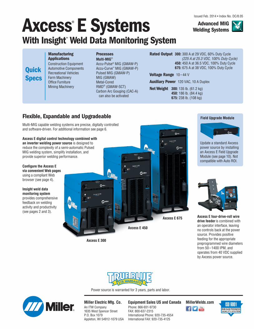
Quick Specs Processes Multi-MIG ® Accu-Pulse ® MIG (GMAW-P) Accu-Curve ™ MIG (GMAW-P) Pulsed MIG (GMAW-P) MIG (GMAW) Metal-Cored RMD ® (GMAW-SCT) Carbon Arc Gouging (CAC-A) can also be activated Manufacturing Applications Construction Equipment Automotive Components Recreational Vehicles Farm Machinery Office Furniture Mining Machinery Issued Feb. 2014 • Index No. DC/8.05 Rated Output 300: 300 A at 29 VDC, 60% Duty Cycle (225 A at 25.3 VDC, 100% Duty Cycle) 450: 450 A at 36.5 VDC, 100% Duty Cycle 675: 675 A at 38 VDC, 100% Duty Cycle Voltage Range 10 – 44 V Auxiliary Power 120 VAC, 10 A Duplex Net Weight 300: 135 lb. (61.2 kg) 450: 186 lb. (84.4 kg) 675: 238 lb. (108 kg) Power source is warranted for 3 years, parts and labor. Axcess E 450 Axcess E 675 Axcess E 300 Flexible, Expandable and Upgradeable Multi-MIG capable welding systems are precise, digitally controlled and software-driven. For additional information see page 6. Axcess E digital control technology combined with an inverter welding power source is designed to reduce the complexity of a semi-automatic Pulsed MIG welding system, simplify installation, and provide superior welding performance. Insight weld data monitoring system provides comprehensive feedback on welding activity and productivity (see pages 2 and 3). Configure the Axcess E via convenient Web pages using a compliant Web browser (see page 4). Axcess E four-drive-roll wire drive feeder is combined with an operator interface, leaving no controls back at the power source. Provides positive feeding for the appropriate preprogrammed wire diameters from 50 – 1400 IPM, and operates from 40 VDC supplied by Axcess power source. Update a standard Axcess power source by installing an Axcess E Field Upgrade Module (see page 10). Not compatible with Auto ROI. Field Upgrade Module Axcess ® E Systems With Insight ™ Weld Data Monitoring System Miller Electric Mfg. Co. An ITW Company 1635 West Spencer Street P.O. Box 1079 Appleton, WI 54912-1079 USA MillerWelds.com Equipment Sales US and Canada Phone: 866-931-9730 FAX: 800-637-2315 International Phone: 920-735-4554 International FAX: 920-735-4125 Advanced MIG Welding Systems
Transcript of Axcess E Systems - Assistência · RMD ® (GMAW-SCT) Carbon ... Miller Electric Mfg. Co. An ITW...
QuickSpecs
ProcessesMulti-MIG®
Accu-Pulse® MIG (GMAW-P)Accu-Curve™ MIG (GMAW-P)Pulsed MIG (GMAW-P)MIG (GMAW)Metal-CoredRMD® (GMAW-SCT)Carbon Arc Gouging (CAC-A)
can also be activated
ManufacturingApplicationsConstruction EquipmentAutomotive ComponentsRecreational VehiclesFarm MachineryOffice FurnitureMining Machinery
Issued Feb. 2014 • Index No. DC/8.05
Rated Output 300: 300 A at 29 VDC, 60% Duty Cycle(225 A at 25.3 VDC, 100% Duty Cycle)
450: 450 A at 36.5 VDC, 100% Duty Cycle675: 675 A at 38 VDC, 100% Duty Cycle
Voltage Range 10 – 44 V
Auxiliary Power 120 VAC, 10 A Duplex
Net Weight 300: 135 lb. (61.2 kg)450: 186 lb. (84.4 kg)675: 238 lb. (108 kg)
Power source is warranted for 3 years, parts and labor.
Axcess E 450
Axcess E 675
Axcess E 300
Flexible, Expandable and UpgradeableMulti-MIG capable welding systems are precise, digitally controlledand software-driven. For additional information see page 6.
Axcess E digital control technology combined withan inverter welding power source is designed toreduce the complexity of a semi-automatic PulsedMIG welding system, simplify installation, andprovide superior welding performance.
Insight weld datamonitoring systemprovides compre hen sivefeedback on weldingactivity and productivity(see pages 2 and 3).
Configure the Axcess Evia convenient Web pagesusing a compliant Webbrowser (see page 4).
Axcess E four-drive-roll wiredrive feeder is combined with an operator interface, leavingno controls back at the powersource. Provides positivefeeding for the appropriatepreprogrammed wire diametersfrom 50 –1400 IPM, andoperates from 40 VDC suppliedby Axcess power source.
Update a standard Axcesspower source by installingan Axcess E Field UpgradeModule (see page 10). Notcompatible with Auto ROI.
Field Upgrade Module
Axcess® E SystemsWith Insight™ Weld Data Monitoring System
Miller Electric Mfg. Co.An ITW Company1635 West Spencer StreetP.O. Box 1079Appleton, WI 54912-1079 USA
MillerWelds.comEquipment Sales US and CanadaPhone: 866-931-9730FAX: 800-637-2315International Phone: 920-735-4554International FAX: 920-735-4125
Advanced MIGWelding Systems
2
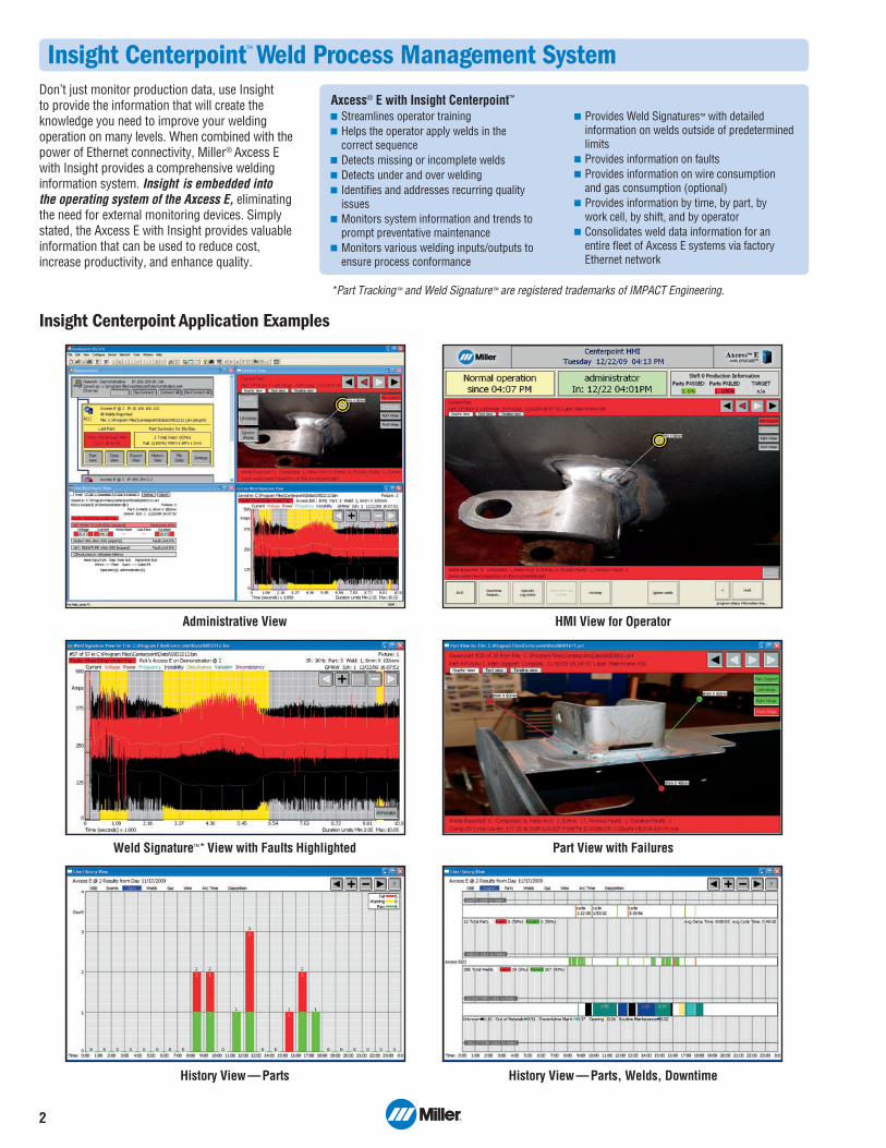
Insight Centerpoint™ Weld Process Management System
History View — Parts
Administrative View
Weld Signature™* View with Faults Highlighted Part View with Failures
HMI View for Operator
History View — Parts, Welds, Downtime
Don’t just monitor production data, use Insight to provide the information that will create theknowledge you need to improve your welding oper ation on many levels. When combined with thepower of Ethernet connectivity, Miller® Axcess Ewith Insight provides a comprehensive weldinginformation system. Insight is embedded into the operating system of the Axcess E, elimi natingthe need for external monitoring devices. Simplystated, the Axcess E with Insight provides valuableinformation that can be used to reduce cost,increase productivity, and enhance quality.
Axcess® E with Insight Centerpoint™
Streamlines operator trainingHelps the operator apply welds in the correct sequenceDetects missing or incomplete weldsDetects under and over weldingIdentifies and addresses recurring qualityissuesMonitors system information and trends toprompt preventative maintenanceMonitors various welding inputs/outputs toensure process conformance
Provides Weld Signatures™ with detailedinformation on welds outside of predeterminedlimitsProvides information on faultsProvides information on wire consumption and gas consumption (optional) Provides information by time, by part, by work cell, by shift, and by operatorConsolidates weld data information for an entire fleet of Axcess E systems via factoryEthernet network
Insight Centerpoint Application Examples
*Part Tracking™ and Weld Signature™ are registered trademarks of IMPACT Engineering.
3
Insight Centerpoint™ Feature GuideWeld Workflow enhances Part Tracking by allowingmanagement to not only govern the application ofwelds, but to specify and govern what other criticalinformation/functions are presented to the operator/welder and when.Cost Calculator is a tool within Centerpoint that allowspart and weld costs to be estimated based on measuredvalues and cost variables entered by the user.Signature Analysis is an advanced weld monitoringmode that provides ability to measure and evaluatepeak/ background voltage and current, pulse width, pulsefrequency, short circuit frequency and power input.Weld Process Production Manager can be used to trackand alarm for basic preventative maintenance tasksincluding total wire used, total gas used (requiresoptional gas flow sensor) total arc time, and total parts.
Standard Optional OptionalInsight Centerpoint™ Feature i100 i1000 i2000
Data capture for current, voltage, WFS, and gas (optional)
Process Control — high/low set points
Jobs (central repository for all Part Tracking™* info)
Detects missing, extra, and incomplete welds
Totalize arc time, wire/gas usage, parts, and welds/time period
Calculates overall equipment effectiveness
Weld history extraction (no full-time PC connection)
Auto Learn
Weld Signature™*—low resolution (averages)
Weld Signature™*—high resolution (1 Khz)
Weld Workflow™
Cost Calculator
Signature Analysis
Weld Process Production Manager (WPPM)
*Part Tracking™ and Weld Signature™ are registered trademarks of IMPACT Engineering.
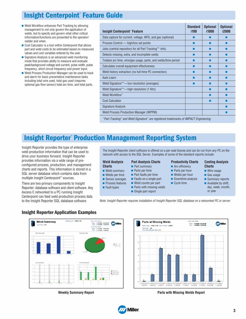
Insight Reporter™ Production Management Reporting System
Weekly Summary Report Parts with Missing Welds Report
Insight Reporter Application Examples
Insight Reporter provides the type of enterprise weld production information that can be used todrive your business forward. Insight Reporterprovides information via a wide range of pre -configured process, production, and manage mentcharts and reports. This information is stored in aSQL server database which contains data frommultiple Insight Centerpoint™ sources. There are two primary components to InsightReporter: database software and client software. AnyAxcess E networked to a PC running InsightCenterpoint can feed weld production process datato the Insight Reporter SQL database software.
The Insight Reporter client software is offered on a per-seat license and can be run from any PC on thenetwork with access to the SQL Server. Examples of some of the standard reports include:
Note: Insight Reporter requires installation of Insight Reporter SQL database on a networked PC or server.
Weld AnalysisCharts
Weld summary Welds per time Sensor averages Process features Fault types
Part Analysis ChartsPart summary Parts per time Part faults per time Faults on a single part Weld counts per part Parts with missing welds Single part report
Productivity ChartsArc-efficiency Parts per hour Welds per hour Downtime analysis Cycle time
Costing AnalysisCharts
Wire usage Gas usage Summary reports Available by shift,day, week, month,or year
4
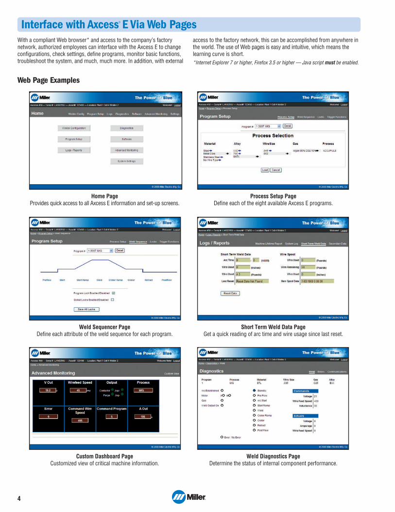
Interface with Axcess® E Via Web Pages
Home Page Provides quick access to all Axcess E information and set-up screens.
Weld Sequencer Page Define each attribute of the weld sequence for each program.
Custom Dashboard Page Customized view of critical machine information.
Short Term Weld Data PageGet a quick reading of arc time and wire usage since last reset.
Process Setup PageDefine each of the eight available Axcess E programs.
Weld Diagnostics PageDetermine the status of internal component performance.
With a compliant Web browser* and access to the company’s factorynetwork, authorized employees can interface with the Axcess E to changeconfigurations, check settings, define programs, monitor basic functions,troubleshoot the system, and much, much more. In addition, with external
access to the factory network, this can be accomplished from anywhere inthe world. The use of Web pages is easy and intuitive, which means thelearning curve is short.*Internet Explorer 7 or higher, Firefox 3.5 or higher — Java script must be enabled.
Web Page Examples
5
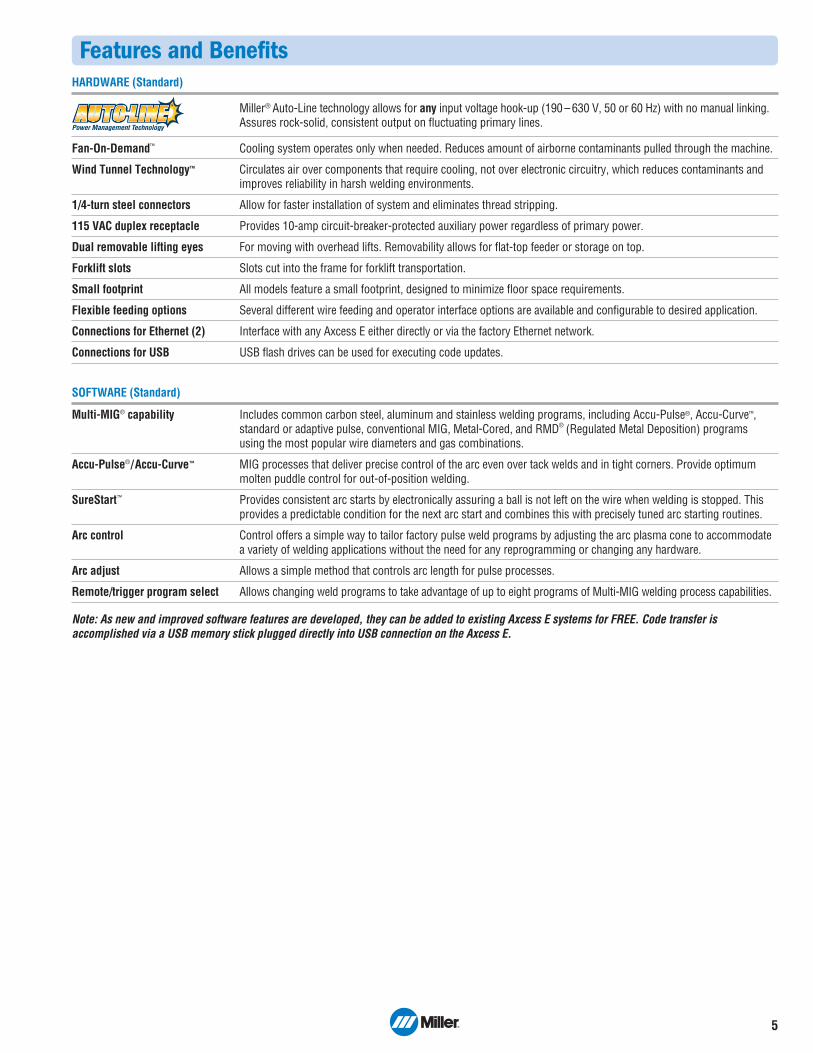
Features and BenefitsHARDWARE (Standard)
Miller® Auto-Line technology allows for any input voltage hook-up (190 – 630 V, 50 or 60 Hz) with no manual linking.Assures rock-solid, consistent output on fluctuating primary lines.
Fan-On-Demand™ Cooling system operates only when needed. Reduces amount of airborne contaminants pulled through the machine.
Wind Tunnel Technology™ Circulates air over components that require cooling, not over electronic circuitry, which reduces contaminants and improves reliability in harsh welding environments.
1/4-turn steel connectors Allow for faster installation of system and eliminates thread stripping.
115 VAC duplex receptacle Provides 10-amp circuit-breaker-protected auxiliary power regardless of primary power.
Dual removable lifting eyes For moving with overhead lifts. Removability allows for flat-top feeder or storage on top.
Forklift slots Slots cut into the frame for forklift transportation.
Small footprint All models feature a small footprint, designed to minimize floor space requirements.
Flexible feeding options Several different wire feeding and operator interface options are available and configurable to desired application.
Connections for Ethernet (2) Interface with any Axcess E either directly or via the factory Ethernet network.
Connections for USB USB flash drives can be used for executing code updates.
SOFTWARE (Standard)
Multi-MIG® capability Includes common carbon steel, aluminum and stainless welding programs, including Accu-Pulse®, Accu-Curve™, standard or adaptive pulse, conventional MIG, Metal-Cored, and RMD® (Regulated Metal Deposition) programs using the most popular wire diameters and gas combinations.
Accu-Pulse®/Accu-Curve™ MIG processes that deliver precise control of the arc even over tack welds and in tight corners. Provide optimum molten puddle control for out-of-position welding.
SureStart™ Provides consistent arc starts by electronically assuring a ball is not left on the wire when welding is stopped. This provides a predictable condition for the next arc start and combines this with precisely tuned arc starting routines.
Arc control Control offers a simple way to tailor factory pulse weld programs by adjusting the arc plasma cone to accommodate a variety of welding applications without the need for any reprogramming or changing any hardware.
Arc adjust Allows a simple method that controls arc length for pulse processes.
Remote/trigger program select Allows changing weld programs to take advantage of up to eight programs of Multi-MIG welding process capabilities.
Note: As new and improved software features are developed, they can be added to existing Axcess E systems for FREE. Code transfer isaccomplished via a USB memory stick plugged directly into USB connection on the Axcess E.
6
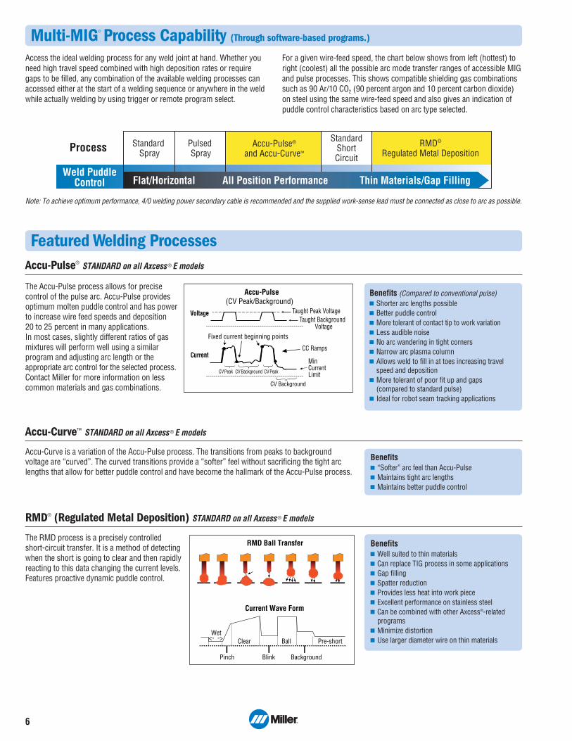
Featured Welding ProcessesAccu-Pulse® STANDARD on all Axcess ® E models
The Accu-Pulse process allows for precisecontrol of the pulse arc. Accu-Pulse providesoptimum molten puddle control and has powerto increase wire feed speeds and deposition 20 to 25 percent in many applications.In most cases, slightly different ratios of gasmixtures will perform well using a similarprogram and adjusting arc length or theappropriate arc control for the selected process.Contact Miller for more information on lesscommon materials and gas combinations.
Benefits (Compared to conventional pulse)Shorter arc lengths possibleBetter puddle controlMore tolerant of contact tip to work variationLess audible noiseNo arc wandering in tight cornersNarrow arc plasma columnAllows weld to fill in at toes increasing travelspeed and depositionMore tolerant of poor fit up and gaps (compared to standard pulse)Ideal for robot seam tracking applications
Accu-Pulse(CV Peak/Background)
Taught Peak VoltageTaught Background
Voltage
Voltage
CurrentCC Ramps
Fixed current beginning points
CV Peak CV PeakCV Background
Min Current Limit
CV Background
Accu-Curve™ STANDARD on all Axcess ® E models
Accu-Curve is a variation of the Accu-Pulse process. The transitions from peaks to backgroundvoltage are “curved”. The curved transitions provide a “softer” feel without sacrificing the tight arclengths that allow for better puddle control and have become the hallmark of the Accu-Pulse process.
Benefits“Softer” arc feel than Accu-PulseMaintains tight arc lengthsMaintains better puddle control
RMD® (Regulated Metal Deposition) STANDARD on all Axcess ® E models
The RMD process is a precisely controlled short-circuit transfer. It is a method of detectingwhen the short is going to clear and then rapidlyreacting to this data changing the current levels.Features proactive dynamic puddle control.
BenefitsWell suited to thin materialsCan replace TIG process in some applicationsGap fillingSpatter reductionProvides less heat into work pieceExcellent performance on stainless steelCan be combined with other Axcess®-relatedprogramsMinimize distortionUse larger diameter wire on thin materials
Current Wave Form
RMD Ball Transfer
Wet<- ->
Pinch
Clear
Blink
Ball
Background
Pre-short
Process RMD® Regulated Metal Deposition
Standard Spray
Pulsed Spray
Accu-Pulse®
and Accu-Curve™
StandardShortCircuit
Flat/Horizontal All Position Performance Thin Materials/Gap FillingWeld Puddle
Control
Note: To achieve optimum performance, 4/0 welding power secondary cable is recommended and the supplied work-sense lead must be connected as close to arc as possible.
Multi-MIG® Process Capability (Through software-based programs.)
Access the ideal welding process for any weld joint at hand. Whether youneed high travel speed combined with high deposition rates or requiregaps to be filled, any combination of the available welding processes canaccessed either at the start of a welding sequence or anywhere in the weldwhile actually welding by using trigger or remote program select.
For a given wire-feed speed, the chart below shows from left (hottest) toright (coolest) all the possible arc mode transfer ranges of accessible MIGand pulse processes. This shows compatible shielding gas combinationssuch as 90 Ar/10 CO2 (90 percent argon and 10 percent carbon dioxide)on steel using the same wire-feed speed and also gives an indication ofpuddle control characteristics based on arc type selected.
7
1
26
5
3
4
78
9
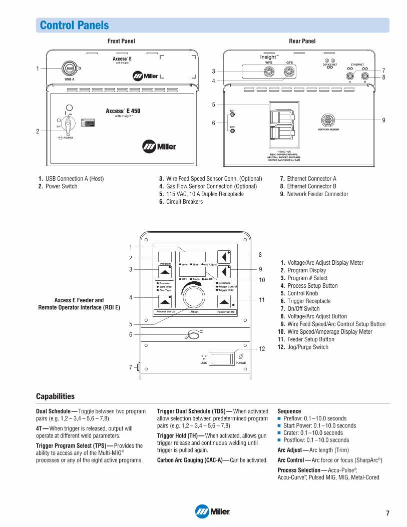
Control Panels
1. USB Connection A (Host)2. Power Switch
3. Wire Feed Speed Sensor Conn. (Optional)4. Gas Flow Sensor Connection (Optional)5. 115 VAC, 10 A Duplex Receptacle6. Circuit Breakers
7. Ethernet Connector A8. Ethernet Connector B9. Network Feeder Connector
1. Voltage/Arc Adjust Display Meter2. Program Display3. Program # Select4. Process Setup Button5. Control Knob6. Trigger Receptacle7. On/Off Switch8. Voltage/Arc Adjust Button9. Wire Feed Speed/Arc Control Setup Button
10. Wire Speed/Amperage Display Meter11. Feeder Setup Button12. Jog/Purge Switch
Front Panel Rear Panel
Program
ProcessWire TypeGas Type
Volts Time Arc Adjust
WFS Amps Arc Ctl
Process Set Up Adjust Feeder Set Up
Trigger HoldTrigger ControlSequence
5
4
7
6
3
2
18
9
11
12
10
Axcess E Feeder and Remote Operator Interface (ROI E)
Capabilities
Dual Schedule — Toggle between two programpairs (e.g. 1,2 – 3,4 – 5,6 – 7,8).
4T — When trigger is released, output willoperate at different weld parameters.
Trigger Program Select (TPS) — Provides theability to access any of the Multi-MIG®
processes or any of the eight active programs.
Trigger Dual Schedule (TDS) — When activatedallow selection between predetermined programpairs (e.g. 1,2 – 3,4 – 5,6 – 7,8).
Trigger Hold (TH)—When activated, allows guntrigger release and continuous welding untiltrigger is pulled again.
Carbon Arc Gouging (CAC-A)—Can be activated.
SequencePreflow: 0.1 –10.0 secondsStart Power: 0.1 –10.0 secondsCrater: 0.1 –10.0 secondsPostflow: 0.1 –10.0 seconds
Arc Adjust — Arc length (Trim)
Arc Control — Arc force or focus (SharpArc®)
Process Selection — Accu-Pulse®, Accu-Curve™, Pulsed MIG, MIG, Metal-Cored

8
AND
The Axcess E platform is designed to provide multiple wire feeding configurations suited to the unique needs of modern manufacturing applications andindustries. It utilizes many common components to minimize both part and maintenance complexity. All motors operate on 40 VDC provided by theAxcess E power supply and have a wire feed speed range of 50–1400 inches per minute. A common operator interface is used on all (see page 7).
Power Source Specifications (Subject to change without notice.)
Typical Installations (Semi-automatic Pulsed MIG or conventional MIG)
Model
AxcessE 300
AxcessE 450
AxcessE 675
Rated Output
300 A at 29 VDC,60% Duty Cycle(225 A at 25.3 VDC,100% Duty Cycle)
450 A at 36.5 VDC,100% Duty Cycle
675 A at 38 VDC,100% Duty Cycle
VoltageRange
10 – 44 V
10 – 44 V
10 – 44 V
AmperageRange
5 – 400 A
5 – 600 A
5 – 900 A
Max. Open-Circuit Voltage
80 VDC
80 VDC
80 VDC
Dimensions
300 H: 26.5 in. (673 mm)450 H: 34.5 in. (876 mm)675 H: 42.5 in. (1080 mm)
W: 17.094 in. (434 mm)D: 21.75 in. (553 mm)
NetWeight
135 lb.(61.2 kg)
186 lb.(84.4 kg)
238 lb.(108 kg)
StandardInstallation
ROI Option InstallationAllows feeder motor drive to be placed away frompower supply and operatorinterface. Ideal for fixedautomation applications and updating or replacingequipment on booms orother applications whereseparate location of powersource, ROI, and wire drive motor is desirable.
A typical bench/sled feederinstallation. For use when the feeder is placed on thepower supply, a bench oran optional cart.
Amps Input at Rated Output, 50/60 Hz, 3-Phase208 V 230 V 400 V 460 V 575 V KVA KW
33 29.7 16.9 14.6 11.6 11.7 11.2
— 60 33.7 28.8 22.8 23.8 22.9
— 89.7 — 43.7 34.8 35.7 34.4
Certified by Canadian Standards Association to both the Canadian and U.S. Standards.
Wire Feeder Options
DeviceNetInterconnectingFeeder Control
Cable(see page 10)
Motor ControlCable
(see page 10)
Axcess E Power Source ROI E(Remote Operator Interface)
AA-40GB Wire Drive Motor Assembly(Drive rolls must be ordered separately.)
Gun (must be ordered
separately.)
DeviceNetInterconnectingFeeder Control
Cable(see page 10)
EthernetNetwork
ConnectionCable
(see page 10)
Axcess E Power Source Axcess E Wire Feeder (Drive rolls must be ordered separately.)
Gun (must be ordered
separately.)
EthernetNetwork
ConnectionCable
(see page 10)
Feeder Base#195 369 (see page 11)
Boom RetrofitApplications
21-ft. Trigger Control Cable #300 129
Flexible Mounting Options
21
3 41
1
2
AND AND
*For available lengths visit MillerWelds.com/equiptoweld.**This is the wire feed speed range while using MIG. With Pulsed MIG, the wire feed speed range may be more limited.
Model
Axcess EBench/SledFeeder
GasValve
Included
Type ofInput Power
40 VDC (fromAxcess)
Connection to Power Source
DeviceNet Interconnecting Feeder Control Cable*(Order separately)
Wire Feed Speed Range**
50 –1400 IPM (1.3 – 35.56 MPM)
Dual FeederDimensions
H: 15 in. (381 mm)W: 19 in. (483 mm)D: 34 in. (863 mm)
Single Feeder Dimensions
H: 14.5 in. (368 mm)W: 12.5 in. (318 mm)D: 27 in. (686 mm)
Wire DiameterRange
.035 – 3/32 in. (0.9 –1.6 mm)
Net Weight(Feeder only)
Single Feeder46 lb. (21 kg)Dual Feeder87 lb. (39 kg)
Axcess E Single Feeder #300 677Axcess E Dual Feeder #300 801Feeder is designed specifically for Axcess E. Provides single-rangecontrol of 50–1400 inches per minute. Dual-wire model provides thesame functionality as single-wire version, but is ideal when two differentwire types need to be available at the same time. Digitally communicateswith Axcess E power source via DeviceNet Interconnecting FeederControl Cable. Includes 50-foot volt-sense lead.
Wire feeders do NOTinclude drive rolls,gun or requiredDeviceNetInterconnectingFeeder Control Cable.These must beordered separately.
Single Feeder Dual Feeder
9
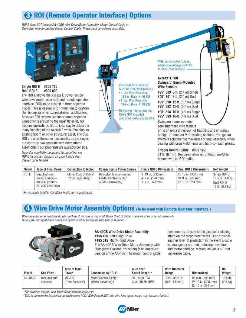
Model
AA-40GB
Gas Valve
Included andenclosed
Type of InputPower
40 VDC (from Axcess E)
Connection to ROI E
Motor Control Cable*(Order separately)
Wire Feed Speed Range**
50 –1400 IPM (1.3 – 35.56 MPM)
Dimensions
H: 8 in. (203 mm)W: 12 in. (305 mm)D: 10 in. (254 mm)
Wire DiameterRange
.035 – 3/32 in. (0.9 –1.6 mm)
NetWeight
16.5 lb. (7.5 kg)
*For available lengths visit MillerWelds.com/equiptoweld.**This is the wire feed speed range while using MIG. With Pulsed MIG, the wire feed speed range may be more limited.
ROI (Remote Operator Interface) Options
Wire Drive Motor Assembly Options (To be used with Remote Operator Interface.)
Single ROI E #300 726Dual ROI E #300 800The ROI E allows the Axcess E power supply,wire drive motor assembly and remote operatorinterface (ROI) to be located in three separateplaces. This is desirable for mounting to customjibs, booms or other extended-reach applications.Since an ROI system can incorporate separatecomponents providing the most flexibility forcustom appli cations, it’s an ideal way to obtain themany benefits of the Axcess E while retaining anexisting boom or other structural asset. The dualROI provides the same functionality as the single,but controls two separate wire drive motorassemblies. Four programs are available per side.Note: For non-Miller boom and jib mounting, see ROI E installation diagram on page 8 and selectdesired cable lengths.
AA-40GB Wire Drive Motor Assembly#195 426 Left-Hand Drive#195 515 Right-Hand DriveThe AA-40GB Wire Drive Motor Assembly withOCP (Over Current Protection) is an improvedversion of the AA-40G. The motor control cable
now mounts directly to the gas box, reducingstrain on the tachometer wires. OCP providesanother layer of protection in the event a cable is damaged or shorted, reducing downtime and motor damage. Motors include a 50-foot volt-sense cable.
Wire drive motor assemblies do NOT include drive rolls or required Motor Control Cable. These must be ordered separately.Note: Left- and right-hand drives are determined by facing the wire feed gun outlet.
Pipe Post NOT included. Must be ordered separately. • 4-foot Pipe Post with
18-inch Base #149 838• 6-foot Pipe Post with
18-inch Base #149 839
DeviceNet InterconnectingCable NOT included (required, order separately).
MIG gun included (one forsingle-wire models and twofor dual-wire models).
ROI E does NOT include AA-40GB Wire Drive Motor Assembly, Motor Control Cable or DeviceNet Interconnecting Feeder Control Cable. These must be ordered separately.
3
4
Axcess® E ROISwingarc™ Boom-Mounted Wire Feeders#951 389 8-ft. (2.4 m) Single#951 391 8-ft. (2.4 m) Dual#951 390 12-ft. (3.7 m) Single#951 392 12-ft. (3.7 m) Dual#951 394 16-ft. (4.9 m) Single#951 393 16-ft. (4.9 m) DualSwingarc boom-mounted semiautomatic wire feeders bring an extra dimension of flexibility and efficiency to high-production MIG welding stations. You get aneffective solution that maximizes output, especially whendealing with large weldments and hard-to-reach places.
Trigger Control Cable #300 12921 ft. (6.4 m). Required when retrofitting non-Millerbooms with an ROI option.
*For available lengths visit MillerWelds.com/equiptoweld.
Model
ROI E
Type of Input Power
Supplied from power source —40 VDC (motor), 24 VDC (interface)
Connection to Motor
Motor Control Cable*(Order separately)
Connection to Power Source
DeviceNet InterconnectingFeeder Control Cable*(Order separately)
Single ROI E Dimensions
H: 13 in. (330 mm)W: 7 in. (178 mm)D: 7 in. (178 mm)
Dual ROI E Dimensions
H: 13 in. (330 mm)W: 9 in. (229 mm)D: 10 in. (254 mm)
Net Weight
Single ROI E10.5 lb. (4.8 kg)Dual ROI E13 lb. (5.9 kg)
Consulting Services
Field Application Support #195 480Axcess® E systems may require factory-trained technical support, depending on thecomplexity of the application and the localavailability and capability of qualified weldingengineers or technology experts. Contact thefactory with questions. Factory support isavailable at a flat rate of $1250.00 per day(plus expenses) when scheduled more than 10 days in advance. With less than 10-day notice, rates may be higher. Ratesare based on a 10-hour day, including travel.One day minimum.
Axcess® E Field Upgrade Module #300 641 FieldUpgrade your investment in standard Axcessequipment. Standard Axcess power sources can beupgraded to Axcess E systems with the addition ofthe Axcess E field upgrade module. This modulecomes with everything you need for installation.Note: Not compatible with Auto ROI.
DeviceNet Interconnecting Feeder Control Cables*#242 209 005 5 ft. (1.5 m)#242 209 010 10 ft. (3 m)#242 209 025 25 ft. (7.6 m)#242 209 050 50 ft. (15.2 m)These specially designed EMI (Electrical MagneticInterference) protected and shielded feedercontrol cables are required, but not includedwith Axcess feeders or ROI. Determine lengthneeded and order separately. *For additional lengths visit MillerWelds.com/equiptoweld.
Motor Control Cables*#242 395 010 10 ft. (3 m)#242 395 020 20 ft. (6.1 m)#242 395 030 30 ft. (9 m)#242 395 050 50 ft. (15.2 m)Includes overmolded connections on high-flexcables for optimal service life.*For additional lengths visit MillerWelds.com/equiptoweld.
Volt-Sense Cable* #242 208 050 50 ft. (15.2 m)Replacement cable. One cable supplied withevery feeder or drive motor.*For additional lengths visit MillerWelds.com/equiptoweld.
Ethernet Network Connection Cables #300 734 9.8 ft. (3 m)#300 735 16.4 ft. (5 m)#300 736 32.8 ft. (10 m)Industrial-grade 360 degree shielded Cat 5Ethernet cable with conventional RJ45overmolded four-pole connector on one end toconnect to factory network, and industrial M12overmolded connector on the other end toattach to Axcess E power source. Cable supports10/100 Mbits-per-second transmission rate.
ADAM DI/O Module #300 803Provides a digital I/O interfacefor communication between arobot /PLC and the Axcess Epower supply. The interfaceallows for the interaction of arobot or PLC and the Insight
Centerpoint application. This module is optionalfor semi-automatic Axcess E models.
Axcess® E Sourcing I/O Kit #301 150 For Axcess E and Auto-Axcess E.
10
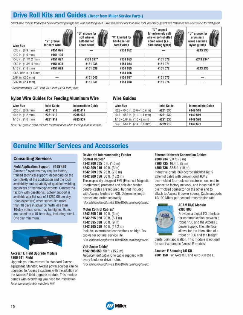
Drive Roll Kits and Guides (Order from Miller Service Parts.)
Genuine Miller® Services and Accessories
Wire Size.035 in. (0.9 mm) #151 026 — #151 052 — #243 233.040 in. (1.0 mm) #161 190 — — — —.045 in. (1.1/1.2 mm) #151 027 #151 037* #151 053 #151 070 #243 234*.052 in. (1.3/1.4 mm) #151 028 #151 038 #151 054 #151 071 —1/16 in. (1.6 mm) #151 029 #151 039 #151 055 #151 072 #243 235.068/.072 in. (1.8 mm) — — #151 056 — —5/64 in. (2.0 mm) — #151 040 #151 057 #151 073 —3/32 in. (2.4 mm) — #151 041 #151 058 #151 074 —
Select drive roll kits from chart below according to type and wire size being used. Drive roll kits include four drive rolls, necessary guides and feature an anti-wear sleeve for inlet guide.
*Accommodates .045- and .047-inch (3/64-inch) wire.
“V” groove for hard wire
“U” groove forsoft wire or soft-shelledcored wires
“U” groove foraluminum
wires containsnylon guides
“V” knurled forhard-shelled cored wires
“U” cogged for extremely soft
wire or soft-shelledcored wires (i.e., hard facing types)
Wire Size Inlet Guide Intermediate Guide.035 in. (0.9 mm) #221 912 #242 417.047 in. (1.2 mm) #221 912 #205 9361/16 in. (1.6 mm) #221 912 #205 937
Nylon Wire Guides for Feeding Aluminum Wire
Note: “U” groove drive rolls are recommended when feeding aluminum wire.
Wire Size Inlet Guide Intermediate Guide.023 –.040 in. (0.6 –1.0 mm) #221 030 #149 518.045 –.052 in. (1.1 –1.4 mm) #221 030 #149 5191/16 – 5/64 in. (1.6 – 2 mm) #221 030 #149 5203/32 –7/64 in. (2.4 – 2.8 mm) #229 919 #149 521
Wire Guides
11
Running Gear Cylinder Rack #300 408Fits Axcess E 300 and 450 models. Holds twolarge gas cylinders and has gun cable hangersand a consumable drawer in front for easyaccess. A convenient handle allows the cart to be pulled easily through doorways. Systemcomponents including power source, single- or dual feeders, and Coolmate™ V3 can bemounted to the cart and secured.
Industrial MIG 4/0 Kit #300 390Consists of Miller | Smith® regulator/flowmeterwith 10-foot (3 m) gas hose, 10-foot (3 m). 4/0 feeder weld cable with lugs, and 15-foot (4.6 m) work cable with 600-amp C-clamp.
Axcess® EFeeder Baseand SpoolSupport #195 369Sheet metalconstruction.Allows mountingof AA-40GB
motor (if desired) when using ROI option.
Hub and SpindleAssembly #072 094
Spindle Support#092 989
Wire Reel Assembly #108 008
Spool Covers #057 607
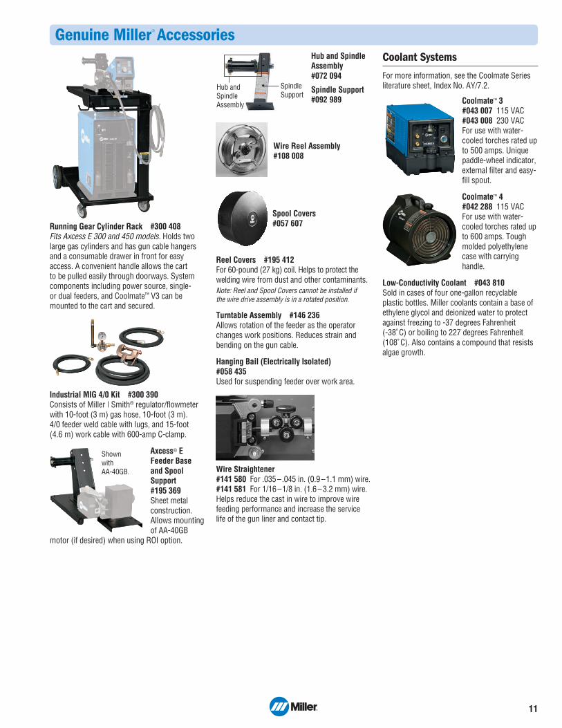
Reel Covers #195 412For 60-pound (27 kg) coil. Helps to protect thewelding wire from dust and other contaminants.Note: Reel and Spool Covers cannot be installed if the wire drive assembly is in a rotated position.
Turntable Assembly #146 236Allows rotation of the feeder as the operatorchanges work positions. Reduces strain andbending on the gun cable.
Hanging Bail (Electrically Isolated) #058 435Used for suspending feeder over work area.
Wire Straightener #141 580 For .035–.045 in. (0.9–1.1 mm) wire.#141 581 For 1/16–1/8 in. (1.6–3.2 mm) wire.Helps reduce the cast in wire to improve wirefeeding performance and increase the servicelife of the gun liner and contact tip.
Coolant Systems
For more information, see the Coolmate Seriesliterature sheet, Index No. AY/7.2.
Coolmate™ 3#043 007 115 VAC#043 008 230 VACFor use with water-cooled torches rated upto 500 amps. Uniquepaddle-wheel indicator,external filter and easy-fill spout.
Coolmate™ 4 #042 288 115 VACFor use with water-cooled torches rated upto 600 amps. Toughmolded polyethylenecase with carryinghandle.
Low-Conductivity Coolant #043 810Sold in cases of four one-gallon recyclableplastic bottles. Miller coolants contain a base ofethylene glycol and deionized water to protectagainst freezing to -37 degrees Fahrenheit (-38˚ C) or boiling to 227 degrees Fahrenheit(108˚ C). Also contains a compound that resistsalgae growth.
Genuine Miller® Accessories
SpindleSupport
Hub andSpindleAssembly
Shown with AA-40GB.

Semi-Automatic Equipment Options Stock No. Description Qty. Price
Axcess® E 300 #907 440 Power source onlyAxcess® E 450 #907 439 Power source onlyAxcess® E 675 #907 441 Power source onlyAxcess® E Field Upgrade Module #300 641 Field. Upgrades standard semi-automatic power source to Axcess E.
Not compatible with Auto ROIInsight™ Software Upgrades #300 812 Field. Upgrades Insight i100 to i1000
#300 815 Field. Upgrades Insight i100 to i2000#300 830 Field. Upgrades Insight i1000 to i2000
Insight Centerpoint™ #300 708 Individual license. Weld data monitoring system software#300 765 Site license
Insight Reporter™ #300 709 Management reporting system client softwareInsight Reporter™ SQL Database #300 710 Management reporting system database software (one required per server)
Wire Feed Options (see page 8 and 9) See page 8 for connection diagram and required cablesAxcess® E Feeder #300 677 Single-wire feeder. Order DeviceNet Interconnecting Feeder Control Cable separately
#300 801 Dual-wire feeder. Order DeviceNet Interconnecting Feeder Control Cable separatelyROI E (Remote Operator Interface) #300 726 Single-wire model
#300 800 Dual-wire modelAxcess® E ROI Swingarc™ Boom #951 389 Single, 8-ft. (2.4 m) boom
#951 391 Dual, 8-ft. (2.4 m) boom#951 390 Single, 12-ft. (3.7 m) boom#951 392 Dual, 12-ft. (3.7 m) boom#951 394 Single, 16-ft. (4.9 m) boom#951 393 Dual, 16-ft. (4.9 m) boom
AA-40GB Wire Drive Motor Assembly #195 426 Left-hand wire drive assembly #195 515 Right-hand wire drive assembly
Drive Roll Kit (Required) and Guides See page 10
Installation CablesTrigger Control Cable (21 ft./6.4 m) #300 129 See page 9. See page 8 for connection diagram DeviceNet Communication Cables See page 10. See page 8 for the connection diagram Motor Control Cable See page 10. See page 8 for the connection diagram Volt-Sense Cable (50 ft./15.2 m) #242 208 050 Included with drive motor. See page 10Ethernet Network Connection Cables See page 10. See page 8 for the connection diagram
Services and AccessoriesField Application Support #195 480 One day minimum, not subject to discount. See page 10ADAM DI/O Module #300 803 Optional for semi-automatic Axcess E modelsAxcess® E Sourcing Kit #301 150Running Gear Cylinder Rack #300 408 For 300 and 450 models only. Holds two cylinders, cooler, machine and feederIndustrial MIG 4/0 Kit #300 390 Includes Miller | Smith® regulator/flowmeter with 10-ft. (3 m) gas hose, 10-ft. (3 m)
4/0 feeder weld cable with lugs, and 15-ft. (4.6 m) work cable with 600-amp C-clampAxcess® E Feeder Base/Spool Support #195 369 Allows mounting of AA-40GB motor when using ROI optionHub and Spindle Assembly #072 094Spindle Support #092 989Wire Reel Assembly #108 008Spool Covers #057 607Reel Covers #195 412Turntable Assembly #146 236Hanging Bail (Electrically Isolated) #058 435Wire Straightener See page 11Coolant Systems See page 11
Date: Total Quoted Price:
Ordering Information
© 2013 Miller Electric Mfg. Co.
Distributed by: