AXC-2000BX -...
8
ELECTRONICS FOR SPECIALISTS ELECTRONICS FOR SPECIALISTS ELECTRONICS FOR SPECIALISTS ELECTRONICS FOR SPECIALISTS ELECTRONICS FOR SPECIALISTS ELECTRONICS FOR SPECIALISTS ELECTRONICS FOR SPECIALISTS ELECTRONICS FOR SPECIALISTS ELECTRONICS FOR SPECIALISTS ELECTRONICS FOR SPECIALISTS MONACOR INTERNATIONAL GmbH & Co. KG • Zum Falsch 36 • 28307 Bremen • Germany Copyright © by MONACOR INTERNATIONAL. All rights reserved. A-1776.99.03.08.2018 AXC-2000BX Bestellnummer 18.4540 POWER VIDEO DC 12V + - 1 2 3 4 5 6 7 8 9 genden Inbusschlüssel lösen und nach der Einstellung wieder festdrehen. 5 Einstellungen über das Bildschirmmenü Die Kameraeinstellungen können über ein Bildschirmmenü geändert werden, das sich über Bedientasten (7) oder über die PTZ-Fernsteuerung vom Videorekorder bedienen lässt. Die Fernsteuerung erfolgt mithilfe des COC-Protokolls über das Videokabel. Zum Einblenden des Bildschirmmenüs die mittlere Taste (7) drücken oder am Videorekorder das Steuerkommando „Iris +“ senden oder das „Preset 95“ aufrufen. Das Haupt- menü erscheint: MAIN MENU 1. LENS MANUAL 2. EXPOSURE ↲ 3. BACKLIGHT OFF 4. DAY&NIGHT AUTO↲ 5. NR ↲ 6. SPECIAL ↲ 7. ADJUST ↲ 8. EXIT SAVE&END↲ Mit den Richtungstasten oder durch Steuerkommandos für die vertikale Bewegung (Tilt) einen Menüpunkt wählen. Mit den Richtungstasten oder durch Steuerkommandos für die horizontale Bewegung (Pan) den Wert ändern oder eine Option wählen. Steht hinter einem Menüpunkt oder einer Option das Symbol ↲, kann durch Drücken der mittleren Taste oder das Kommando „Iris +“ (entspricht „Enter“) ein Untermenü aufgerufen oder eine Funktion ausgelöst werden. Alle Einstellmöglichkeiten sind auf der Rückseite dieser Anlei- tung tabellarisch aufgeführt. Diese Anleitung bezieht sich auf das voreingestellte englische Menü. Die Menüsprache kann aber unter 6. SPECIAL↲ 2. LANGUAGE geändert werden. Zum Verlassen des Menüs in der Zeile EXIT die Option SAVE&END↲ (durchgeführte Änderungen werden dabei ge- speichert) oder NOT SAVE↲ (Änderungen werden verwor- fen) wählen und mit der mittleren Taste bzw. „Iris +“ bestätigen. Zum Zurücksetzen aller Einstellungen auf die Werkseinstel- lungen in der Zeile EXIT die Option RESET↲ wählen und mit der mittleren Taste bzw. „Iris +“ bestätigen. Die gewählte Menüsprache bleibt auch nach dem Zurücksetzen erhalten. 6 Technische Daten Bildabtaster: . . . . . . . . . . . .CMOS-Chip, 8,5 mm (1⁄3 ”) Anzahl der Bildpunkte: . . . .max. 1920 × 1080 Auflösung: . . . . . . . . . . . . .1080P/25 Farbmodulationssystem: . . .PAL / NTSC Elektronischer Verschluss: . .1⁄50 – 1⁄50 000 s Videoausgang: . . . . . . . . . .1 V (ss) / 75 Ω Stromversorgung: . . . . . . . .⎓12 V, 150 mA Einsatztemperatur: . . . . . . .−20 °C bis +50 °C Abmessungen: . . . . . . . . . .70 × 60 × 150 mm Gewicht: . . . . . . . . . . . . . . .300 g Änderungen vorbehalten. HD-Überwachungskamera Diese Anleitung richtet sich an Installateure von Videoüberwachungsanlagen. Bitte lesen Sie die An- leitung vor der Installation gründlich durch und heben Sie sie für ein späteres Nachlesen auf. 1 Verwendungsmöglichkeiten Diese hochauflösende Farbkamera ist speziell für den Einsatz in Video-Überwachungsanlagen (CCTV) konzipiert. Mit den Videoformaten HD-TVI, HD-CVI und AHD ist die Übertragung eines hochauflösenden analogen Bildsignals (1080p) über Standard-Koaxialkabel bis zu einer Länge von 300 m möglich. Alternativ lässt sich der Videosignalausgang auch auf das FBAS-(Composite-)Signalformat umschalten. Die Kamera verfügt über eine automatische Tag/Nacht-Umschaltung mit Infrarotsperrfilter, einen automatischen Weißabgleich, eine digitale Rauschunterdrückung und weitere Funktionen, die sich über ein Bildschirmmenü konfigurieren lassen. 2 Wichtige Hinweise für den Gebrauch Die Kamera entspricht allen relevanten Richtlinien der EU und ist deshalb mit gekennzeichnet. • Die Kamera ist nur zur Verwendung im Innenbereich ge- eignet. Bei Außenmontage muss sie in ein wetterfestes Schutzgehäuse eingesetzt werden. • Schützen Sie die Kamera vor Staub, Feuchtigkeit und Hitze (zulässige Einsatztemperatur −20 °C bis +50 °C). • Verwenden Sie für die Reinigung nur ein trockenes, wei- ches Tuch, niemals Chemikalien oder Wasser. • Wird die Kamera zweckentfremdet, nicht richtig installiert oder nicht fachgerecht repariert, kann keine Haftung für daraus resultierende Sach- oder Personenschäden und keine Garantie für die Kamera übernommen werden. Soll die Kamera endgültig aus dem Betrieb genom- men werden, übergeben Sie sie zur umweltgerechten Entsorgung einem örtlichen Recyclingbetrieb. 3 Objektiv Es kann sowohl ein Objektiv mit gleichspannungsgesteuerter Blende (DC-Objektiv) als auch ein Objektiv mit manueller Blendeneinstellung verwendet werden. VORSICHT Schützen Sie den Bildwandler-Chip und die Objektivlinsen vor Staub und Ver- schmutzung und berühren Sie sie auf keinen Fall mit den Fingern. 1) Die Schutzkappe abnehmen. 2) Das Objektiv auf das Gewinde (2) schrauben. Es können sowohl C-Mount-Objektive als auch CS-Mount-Objektive verwendet werden. 3) Bei Verwendung eines Objektivs mit gleichspannungs- gesteuerter Blende dieses über die Buchse (5) an der Seite der Kamera anschließen. Die Buchse hat folgende Pin-Belegung ( ☞ Abbildung): Dämpfungsspule (damp): ➀ = − ➁ = + Antrieb (drive): ➂ = + ➃ = − 4 Installation 1) Um die optimale Montagestelle festzustellen, sollte zu- nächst ein Probebetrieb erfolgen. Danach die Kamera über das Gewinde im Sockel (3) befestigen. Für eine hän- gende Montage kann der Sockel auch auf der Oberseite des Kameragehäuses montiert werden. 2) Die BNC-Buchse VIDEO (6) mit dem Eingang eines Video- rekorders verbinden (z. B. aus der AXR-Serie von MONA- COR) oder mit dem Eingang eines Monitors. Der Ausgang lässt sich auf das gewünschte Signalformat umschalten. Dafür haben die Bedientasten (7) bei länge- rem Drücken (ca. 5 s) folgende Sonderfunktionen: = FBAS-(Composite-)Ausgangssignal = AHD-Ausgangssignal = HD-TVI-Ausgangssignal = HD-CVI-Ausgangssignal 3) An die Steckschraubklemmen (8) ein stabilisiertes Netzge- rät mit einer Gleichspannung von 12 V und einer Dauer- belastbarkeit von 150 mA anschließen (z. B. PSS-1210DC). Ein Adapter für Kleinspannungsstecker 5,5 / 2,1 mm (Außen-/Innendurchmesser) liegt bei. Die Betriebsan- zeige (9) leuchtet. 4) Den Videorekorder und den daran angeschlossenen Monitor einschalten und die Kamera anhand des Monitorbilds ausrichten. Am Objektiv die Entfernung einstellen. Bei einem Objektiv mit manuell einstellbarer Blende diese auf optimale Bildwiedergabe (Schärfen- tiefe und Helligkeit) einstellen. Ist bei korrekt eingestellter Entfernung das Bild unscharf, das Auflagemaß für das Objektiv durch Drehen des Einstellrings (1) korrigieren. Dazu die beiden Feststellschrauben (4) mit dem beilie- Deutsch
Transcript of AXC-2000BX -...

ELECTRONICS FOR SPECIALISTS ELECTRONICS FOR SPECIALISTS ELECTRONICS FOR SPECIALISTS ELECTRONICS FOR SPECIALISTS ELECTRONICS FOR SPECIALISTS ELECTRONICS FOR SPECIALISTS ELECTRONICS FOR SPECIALISTS ELECTRONICS FOR SPECIALISTS ELECTRONICS FOR SPECIALISTS ELECTRONICS FOR SPECIALISTS
MONACOR INTERNATIONAL GmbH & Co. KG • Zum Falsch 36 • 28307 Bremen • Germany Copyright© by MONACOR INTERNATIONAL. All rights reserved. A-1776.99.03.08.2018
AXC-2000BX Bestellnummer 18.4540
POWER
VIDEO
DC 12V
+ −
1 2 3 4 5 6 7 8 9
genden Inbusschlüssel lösen und nach der Einstellung wieder festdrehen.
5 Einstellungen über das BildschirmmenüDie Kameraeinstellungen können über ein Bildschirmmenü geändert werden, das sich über Bedientasten (7) oder über die PTZ-Fernsteuerung vom Videorekorder bedienen lässt. Die Fernsteuerung erfolgt mithilfe des COC-Protokolls über das Videokabel.
Zum Einblenden des Bildschirmmenüs die mittlere Taste (7) drücken oder am Videorekorder das Steuerkommando „Iris +“ senden oder das „Preset 95“ aufrufen. Das Haupt-menü erscheint:
MAIN MENU1. LENS MANUAL2. EXPOSURE 3. BACKLIGHT OFF4. DAY&NIGHT AUTO5. NR 6. SPECIAL 7. ADJUST 8. EXIT SAVE&END
Mit den Richtungstasten oder durch Steuerkommandos für die vertikale Bewegung (Tilt) einen Menüpunkt wählen. Mit den Richtungstasten oder durch Steuerkommandos für die horizontale Bewegung (Pan) den Wert ändern oder eine Option wählen. Steht hinter einem Menüpunkt oder einer Option das Symbol , kann durch Drücken der mittleren Taste oder das Kommando „Iris +“ (entspricht „Enter“) ein Untermenü aufgerufen oder eine Funktion ausgelöst werden.
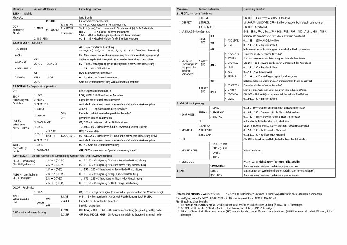
Alle Einstellmöglichkeiten sind auf der Rückseite dieser Anlei-tung tabellarisch aufgeführt. Diese Anleitung bezieht sich auf
das voreingestellte englische Menü. Die Menüsprache kann aber unter 6. SPECIAL 2. LANGUAGE geändert werden.
Zum Verlassen des Menüs in der Zeile EXIT die Option SAVE&END (durchgeführte Änderungen werden dabei ge-speichert) oder NOT SAVE (Änderungen werden verwor-fen) wählen und mit der mittleren Taste bzw. „Iris +“ bestätigen.
Zum Zurücksetzen aller Einstellungen auf die Werkseinstel-lungen in der Zeile EXIT die Option RESET wählen und mit der mittleren Taste bzw. „Iris +“ bestätigen. Die gewählte Menü sprache bleibt auch nach dem Zurücksetzen erhalten.
6 Technische DatenBildabtaster: . . . . . . . . . . . .CMOS-Chip, 8,5 mm (1⁄3 ”)
Anzahl der Bildpunkte: . . . .max. 1920 × 1080
Auflösung: . . . . . . . . . . . . .1080P/25
Farbmodulationssystem: . . .PAL / NTSC
Elektronischer Verschluss: . .1⁄50 – 1⁄50 000 s
Videoausgang: . . . . . . . . . .1 V (ss) / 75 Ω
Stromversorgung: . . . . . . . .12 V, 150 mA
Einsatztemperatur: . . . . . . .−20 °C bis +50 °C
Abmessungen: . . . . . . . . . .70 × 60 × 150 mm
Gewicht: . . . . . . . . . . . . . . .300 g
Änderungen vorbehalten.
HD-Überwachungskamera Diese Anleitung richtet sich an Installateure von Video überwachungsanlagen. Bitte lesen Sie die An-leitung vor der Installation gründlich durch und heben Sie sie für ein späteres Nachlesen auf.
1 VerwendungsmöglichkeitenDiese hochauflösende Farbkamera ist speziell für den Einsatz in Video-Überwachungsanlagen (CCTV) konzipiert. Mit den Videoformaten HD-TVI, HD-CVI und AHD ist die Übertragung eines hochauflösenden analogen Bildsignals (1080p) über Standard-Koaxialkabel bis zu einer Länge von 300 m möglich. Alternativ lässt sich der Videosignalausgang auch auf das FBAS-(Composite-)Signalformat umschalten. Die Kamera verfügt über eine automatische Tag / Nacht-Umschaltung mit Infrarotsperrfilter, einen automatischen Weißabgleich, eine digitale Rauschunterdrückung und weitere Funktionen, die sich über ein Bildschirmmenü konfigurieren lassen.
2 Wichtige Hinweise für den GebrauchDie Kamera entspricht allen relevanten Richtlinien der EU und ist deshalb mit gekennzeichnet.
• Die Kamera ist nur zur Verwendung im Innenbereich ge-eignet. Bei Außenmontage muss sie in ein wetterfestes Schutzgehäuse eingesetzt werden.
• Schützen Sie die Kamera vor Staub, Feuchtigkeit und Hitze (zulässige Einsatztemperatur −20 °C bis +50 °C).
• Verwenden Sie für die Reinigung nur ein trockenes, wei-ches Tuch, niemals Chemikalien oder Wasser.
• Wird die Kamera zweckentfremdet, nicht richtig installiert oder nicht fachgerecht repariert, kann keine Haftung für daraus resultierende Sach- oder Personenschäden und keine Garantie für die Kamera übernommen werden.
Soll die Kamera endgültig aus dem Betrieb genom-men werden, übergeben Sie sie zur umweltgerechten Entsorgung einem örtlichen Recyclingbetrieb.
3 ObjektivEs kann sowohl ein Objektiv mit gleichspannungsgesteuerter Blende (DC-Objektiv) als auch ein Objektiv mit manueller Blendeneinstellung verwendet werden.
VORSICHT Schützen Sie den Bildwandler-Chip und die Objektivlinsen vor Staub und Ver-schmutzung und berühren Sie sie auf keinen Fall mit den Fingern.
1) Die Schutzkappe abnehmen.
2) Das Objektiv auf das Gewinde (2) schrauben. Es können sowohl C-Mount-Objektive als auch CS-Mount-Objektive verwendet werden.
3) Bei Verwendung eines Objektivs mit gleichspannungs-gesteuerter Blende dieses über die Buchse (5) an der Seite der Kamera anschließen. Die Buchse hat folgende Pin-Belegung ( Abbildung):
Dämpfungsspule (damp): ➀ = − ➁ = +Antrieb (drive): ➂ = + ➃ = −
4 Installation1) Um die optimale Montagestelle festzustellen, sollte zu-
nächst ein Probebetrieb erfolgen. Danach die Kamera über das Gewinde im Sockel (3) befestigen. Für eine hän-gende Montage kann der Sockel auch auf der Oberseite des Kameragehäuses montiert werden.
2) Die BNC-Buchse VIDEO (6) mit dem Eingang eines Video-rekorders verbinden (z. B. aus der AXR-Serie von MONA-COR) oder mit dem Eingang eines Monitors.
Der Ausgang lässt sich auf das gewünschte Signal format umschalten. Dafür haben die Bedientasten (7) bei länge-rem Drücken (ca. 5 s) folgende Sonderfunktionen:
= FBAS-(Composite-)Ausgangssignal = AHD-Ausgangssignal = HD-TVI-Ausgangssignal = HD-CVI-Ausgangssignal
3) An die Steckschraubklemmen (8) ein stabilisiertes Netzge-rät mit einer Gleichspannung von 12 V und einer Dauer-belastbarkeit von 150 mA anschließen (z. B. PSS-1210DC). Ein Adapter für Kleinspannungsstecker 5,5 / 2,1 mm (Außen-/Innendurchmesser) liegt bei. Die Betriebsan-zeige (9) leuchtet.
4) Den Videorekorder und den daran angeschlossenen Monitor einschalten und die Kamera anhand des Monitor bilds ausrichten. Am Objektiv die Entfernung einstellen. Bei einem Objektiv mit manuell einstellbarer Blende diese auf optimale Bildwiedergabe (Schärfen-tiefe und Helligkeit) einstellen. Ist bei korrekt eingestellter Entfernung das Bild unscharf, das Auflagemaß für das Objektiv durch Drehen des Einstellrings (1) korrigieren. Dazu die beiden Feststellschrauben (4) mit dem beilie-
Deu
tsch
Menüzeile Auswahl / Untermenü Einstellung; Funktion
1. LENS – Objektiv
MANUAL feste Blende
DC gesteuerte Blende
1. MODE
INDOOR Einsatzbereich: Innenbetrieb
OUTDOOR
1. MIN SHU. 1/25 = max. Verschlusszeit [s] für Außenbetrieb2. MAX SHU. 1⁄50, FLK (= 1⁄100), 1/200 … 1⁄50 000 = min. Verschlusszeit [s] für Außenbetrieb
3. RETURN *RET = zurück zur höheren MenüebeneSAVE&END = Änderungen speichern und Menü verlassen
2. IRIS SPEED 0 … 8 … 15 = Geschwindigkeit für die Blendensteuerung
2. EXPOSURE – Belichtung
1. SHUTTERAUTO = automatische Belichtung1/25, 1⁄50, FLK (= 1⁄100), 1/200 … 1⁄50 000, x 2, x 4, x 6 … x 30 = feste Verschlusszeit [s]
2. AGC 0 … 15 = Bereich der Verstärkungsregelung (0 = keine Verstärkungsregelung)
3. SENS-UPOFF Verlängerung der Belichtungszeit bei schwacher Beleuchtung deaktiviert
AUTO 1. SENS-UP x 2 … x 30 = Verlängerung der Belichtungszeit bei schwacher Beleuchtung 1
4. BRIGHTNESS 1 … 65 … 100 = Bildhelligkeit
5. D-WDR
OFF Dynamikerweiterung deaktiviert
ON 1. LEVEL 0 … 8 = Grad der Dynamikerweiterung
AUTO Grad der Dynamikerweiterung wird automatisch bestimmt
3. BACKLIGHT – Gegenlicht kompensation
OFF keine Gegenlichtkompensation
BLC Aufhellung von Bereichen
1. LEVEL LOW, MIDDLE, HIGH – Grad der Aufhellung
2. AREA Einstellen des aufzuhellenden Bereichs 2
3. DEFAULT setzt alle Einstellungen dieses Untermenüs zurück auf die Werksvorgaben
HSBLC Schwärzung hellster Bildteile
1. SELECT AREA 1 … 4 – einzustellenden Bereich wählen
2. DISPLAYON Einstellen und Aktivieren des gewählten Bereichs 2
OFF gewählten Bereich deaktivieren
3. BLACK MASK ON, OFF – Schwärzung hellster Bildteile ein /aus
4. LEVEL 1 … 50 … 100 = Schwellwert für die Schwärzung hellster Bildteile
5. MODEALL DAY HSBLC immer aktiv
NIGHT 1. AGC LEVEL 0 … 48 … 255 = Schwellwert (HSBLC nur bei schwacher Beleuchtung aktiv)
6. DEFAULT setzt alle Einstellungen dieses Untermenüs zurück auf die Werksvorgaben
WDR erweiterte Dy-namik
1. LEVEL 0 … 4 = Grad der Dynamikerweiterung
2. D&N MODE OFF, AUTO – automatische Dynamikerweiterung aus /ein
4. DAY&NIGHT – Tag- und Nachtbetrieb (Umschaltung zwischen Farb- und Schwarzweißbetrieb)
EXT – Umschaltung über Helligkeitssensor
1. D N (DELAY) 0 … 3 … 60 = Verzögerung für autom. Tag Nacht-Umschaltung
2. N D (DELAY) 0 … 3 … 60 = Verzögerung für autom. Nacht Tag-Umschaltung
AUTO – Umschaltung über Bildhelligkeit
1. D N (AGC) 1 … 250 … 255 = Schwellwert für Tag Nacht-Umschaltung
2. D N (DELAY) 0 … 5 … 60 = Verzögerung für Tag Nacht-Umschaltung
3. N D (AGC) 1 … 170 … 255 = Schwellwert für Nacht Tag-Umschaltung
4. N D (DELAY) 0 … 5 … 60 = Verzögerung für Nacht Tag-Umschaltung
COLOR – Farbbetrieb
B / W Schwarzweißbe-trieb
1. BURST ON, OFF – Farbsynchronsignal (nur wenn für Synchronisation des Monitors nötig)
2. IR SMART
ON 1. LEVEL 0, 1 … 15 = kompensiert im Nahbereich Überbelichtung durch IR-LEDs
2. AREA Einstellen des betreffenden Bereichs 2
OFF Funktion deaktiviert
5. NR – Rauschunterdrückung1. 2DNR OFF, LOW, MIDDLE, HIGH – 2D-Rauschunterdrückung (aus, niedrig, mittel, hoch)
2. 3DNR OFF, LOW, MIDDLE, HIGH – 3D-Rauschunterdrückung (aus, niedrig, mittel, hoch)
Menüzeile Auswahl / Untermenü Einstellung; Funktion
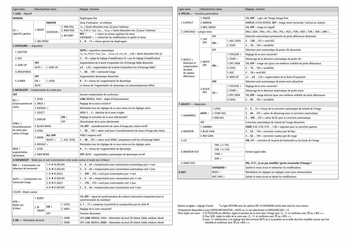
6. SPECIAL – Sonderfunktionen
1. D-EFFECT
1. FREEZE ON, OFF – „Einfrieren“ des Bildes (Standbild)
2. MIRROR MIRROR, V-FLIP, ROTATE, OFF – Bild horizontal/vertikal spiegeln oder rotieren
3. NEG. IMAGE ON, OFF – Negativbild
2. LANGUAGE – Menüsprache ENG, GER, FRA, ITA, SPA, POL, RUS, POR, NED , TUR , HEB , ARB , …
3. DEFECT Erkennung und Kompensation defekter Sensorpixel
1. LIVE DPC
OFF permanente, automatische Pixelfehlererkennung deaktiviert
ON 1. AGC LEVEL 0 … 128 … 255 = AGC-Schwellwert
2. LEVEL 0 … 14 … 100 = Empfindlichkeit
2. WHITE DPC
OFF halbautomatische Erkennung von immerhellen Pixeln deaktiviert
ON
1. POS / SIZE Einstellen des betreffenden Bereichs 2
2. START Start der automatischen Erkennung von immerhellen Pixeln
3. DPC VIEW ON, OFF – Bild schwarz (zur besseren Sichtbarkeit der Pixelfehler)
4. LEVEL 0 … 13 … 100 = Empfindlichkeit
5. AGC 0 … 14 = AGC-Schwellwert
6. SENS-UP x 2 … x 6 … x 30 = Verlängerung der Belichtungszeit
3. BLACK DPC
OFF halbautomatische Erkennung von immerdunklen Pixeln deaktiviert
ON
1. POS / SIZE Einstellen des betreffenden Bereichs 2
2. START Start der automatischen Erkennung von immerdunklen Pixeln
3. DPC VIEW ON, OFF – Bild weiß (zur besseren Sichtbarkeit der Pixelfehler)
4. LEVEL 0 … 95 … 100 = Empfindlichkeit
7. ADJUST – Anpassung
1. SHARPNESSAUTO
1. LEVEL 0 … 5 … 10 = Grad der automatischen Bildschärfekorrektur
2. START AGC 0 … 64 … 255 = Startwert für die Bildschärfekorrektur
3. END AGC 0 … 160 … 255 = Endwert für die Bildschärfekorrektur
OFF automatische Bildschärfekorrektur deaktiviert
2. MONITOR
1. GAMMA USER, 0.45, 0.50, 0.55 … 1.00 = Exponent für Gammakorrektur
2. BLUE GAIN 0 … 52 … 100 = Farbkorrektur Blauanteil
3. RED GAIN 0 … 52 … 100 = Farbkorrektur Rotanteil
3. LSC ON, OFF – Korrektur des Helligkeitsabfalls an den Bildrändern
4. MONITOR OUT
THD (= TVI)
VideosignalformatCHD (= CVI)
CVBS AHD
5. VIDEO OUT. PAL, NTSC; nicht ändern (eventuell Bildausfall)!
8. EXIT
SAVE&END Bildschirmmenü verlassen und Änderungen speichern
RESET Einstellungen auf Werkseinstellungen zurücksetzen (ohne Speichern)
NOT SAVE Bildschirmmenü verlassen und Änderungen verwerfen
Optionen im Fettdruck = Werkseinstellung *Die Zeile RETURN mit den Optionen RET und SAVE&END ist in allen Untermenüs vorhanden.1nur verfügbar, wenn für EXPOSURE \ SHUTTER = AUTO oder 1/25 gewählt und EXPOSURE \ AGC > 02 Zur Einstellung eines Bereichs:
1) Bei Anzeige von POSITION mit , die Position des Bereichs im Bild einstellen und mit bzw. „IRIS +“ bestätigen.2) Bei SIZE mit , die Größe des Bereichs einstellen und mit bzw. „IRIS +“ bestätigen.3) Mit wählen, ob die Einstellung beendet (RET) oder die Position oder Größe noch einmal verändert (AGAIN) werden soll und mit bzw. „IRIS +“
bestätigen.
ELECTRONICS FOR SPECIALISTS ELECTRONICS FOR SPECIALISTS ELECTRONICS FOR SPECIALISTS ELECTRONICS FOR SPECIALISTS ELECTRONICS FOR SPECIALISTS ELECTRONICS FOR SPECIALISTS ELECTRONICS FOR SPECIALISTS ELECTRONICS FOR SPECIALISTS ELECTRONICS FOR SPECIALISTS ELECTRONICS FOR SPECIALISTS
MONACOR INTERNATIONAL GmbH & Co. KG • Zum Falsch 36 • 28307 Bremen • Germany Copyright© by MONACOR INTERNATIONAL. All rights reserved. A-1776.99.03.08.2018
POWER
VIDEO
DC 12V
+ −
1 2 3 4 5 6 7 8 9
AXC-2000BX Order Number 18.4540
HD Surveillance CameraThese instructions are intended for installers of video surveillance systems. Please read the instructions carefully prior to installation and keep them for later reference.
1 ApplicationsThis high-resolution colour camera is specially designed for use in video surveillance systems (CCTV). The video formats HD-TVI, HD-CVI and AHD support transmission of high- resolution analog video signals (1080p) via standard coaxial cables with a maximum length of 300 m. Alternatively, the video signal output can be switched to composite video signal (CVBS). The camera features include automatic white balance, automatic day/night switching with infrared filter, digital noise suppression and other functions to be config-ured via OSD menu.
2 Important NotesThe camera corresponds to all relevant directives of the EU and is therefore marked with .
• The camera is suitable for indoor use only. For outdoor applications, install the camera in a weatherproof housing.
• Protect the camera against dust, humidity and heat (ad-missible ambient temperature range: –20 °C to +50 °C).
• For cleaning only use a dry, soft cloth; never use water or chemicals.
• No guarantee claims for the camera and no liability for any resulting personal damage or material damage will be accepted if the camera is used for other purposes than originally intended, if it is not correctly installed, or if it is not repaired in an expert way.
If the camera is to be put out of operation defini-tively, take it to a local recycling plant for a disposal which is not harmful to the environment.
3 LensA lens with DC voltage-controlled iris (DC lens) or a lens with manual iris adjustment can be used.
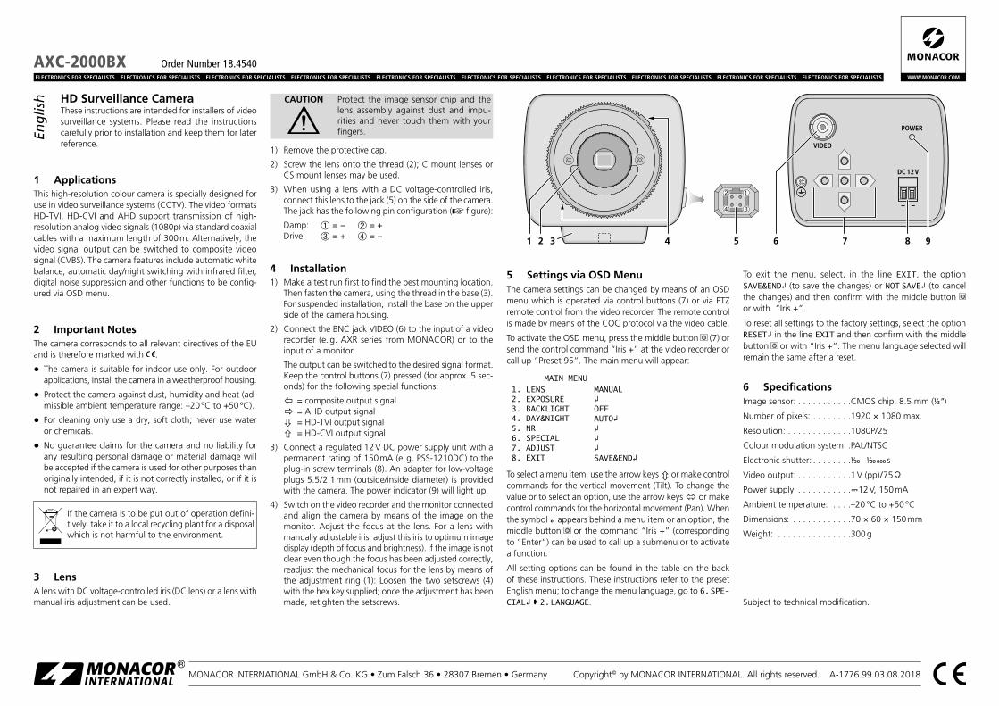
CAUTION Protect the image sensor chip and the lens assembly against dust and impu-rities and never touch them with your fingers.
1) Remove the protective cap.
2) Screw the lens onto the thread (2); C mount lenses or CS mount lenses may be used.
3) When using a lens with a DC voltage-controlled iris, connect this lens to the jack (5) on the side of the camera. The jack has the following pin configuration ( figure):
Damp: ➀ = − ➁ = +Drive: ➂ = + ➃ = −
4 Installation1) Make a test run first to find the best mounting location.
Then fasten the camera, using the thread in the base (3). For suspended installation, install the base on the upper side of the camera housing.
2) Connect the BNC jack VIDEO (6) to the input of a video recorder (e. g. AXR series from MONACOR) or to the input of a monitor.
The output can be switched to the desired signal format. Keep the control buttons (7) pressed (for approx. 5 sec-onds) for the following special functions:
= composite output signal = AHD output signal = HD-TVI output signal = HD-CVI output signal
3) Connect a regulated 12 V DC power supply unit with a permanent rating of 150 mA (e. g. PSS-1210DC) to the plug-in screw terminals (8). An adapter for low-voltage plugs 5.5 / 2.1 mm (outside/inside diameter) is provided with the camera. The power indicator (9) will light up.
4) Switch on the video recorder and the monitor connected and align the camera by means of the image on the monitor. Adjust the focus at the lens. For a lens with manually adjustable iris, adjust this iris to optimum image display (depth of focus and brightness). If the image is not clear even though the focus has been adjusted correctly, readjust the mechanical focus for the lens by means of the adjustment ring (1): Loosen the two setscrews (4) with the hex key supplied; once the adjustment has been made, retighten the setscrews.
5 Settings via OSD MenuThe camera settings can be changed by means of an OSD menu which is operated via control buttons (7) or via PTZ remote control from the video recorder. The remote control is made by means of the COC protocol via the video cable.
To activate the OSD menu, press the middle button (7) or send the control command “Iris +” at the video recorder or call up “Preset 95”. The main menu will appear:
MAIN MENU1. LENS MANUAL2. EXPOSURE 3. BACKLIGHT OFF4. DAY&NIGHT AUTO5. NR 6. SPECIAL 7. ADJUST 8. EXIT SAVE&END
To select a menu item, use the arrow keys or make control commands for the vertical movement (Tilt). To change the value or to select an option, use the arrow keys or make control commands for the horizontal movement (Pan). When the symbol appears behind a menu item or an option, the middle button or the command “Iris +” (corresponding to “Enter”) can be used to call up a submenu or to activate a function.
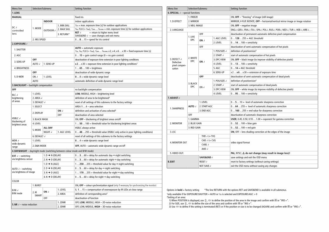
All setting options can be found in the table on the back of these instructions. These instructions refer to the preset English menu; to change the menu language, go to 6. SPE-CIAL 2. LANGUAGE.
To exit the menu, select, in the line EXIT, the option SAVE&END (to save the changes) or NOT SAVE (to cancel the changes) and then confirm with the middle button or with “Iris +”.
To reset all settings to the factory settings, select the option RESET in the line EXIT and then confirm with the middle button or with “Iris +”. The menu language selected will remain the same after a reset.
6 SpecificationsImage sensor: . . . . . . . . . . .CMOS chip, 8.5 mm (1⁄3 ”)
Number of pixels: . . . . . . . .1920 × 1080 max.
Resolution: . . . . . . . . . . . . .1080P/25
Colour modulation system: .PAL/NTSC
Electronic shutter: . . . . . . . .1⁄50 – 1⁄50 000 s
Video output: . . . . . . . . . . .1 V (pp) / 75 Ω
Power supply: . . . . . . . . . . .12 V, 150 mA
Ambient temperature: . . . .–20 °C to +50 °C
Dimensions: . . . . . . . . . . . .70 × 60 × 150 mm
Weight: . . . . . . . . . . . . . . .300 g
Subject to technical modification.
English
Options in bold = factory setting *The line RETURN with the options RET and SAVE&END is available in all submenus.1only available if for EXPOSURE \ SHUTTER = AUTO or 1/25 is selected and EXPOSURE \ AGC > 02 Setting of an area:
1) When POSITION is displayed, use , to define the position of the area in the image and confirm with or “IRIS +”.2) For SIZE, use , to define the size of the area and confirm with or “IRIS +”.3) Use to define if the setting is terminated (RET) or if the position or size is to be changed (AGAIN) and confirm with or “IRIS +”.
Menu line Selection/ Submenu Setting; function
1. LENS
MANUAL fixed iris
DC controlled lens
1. MODE
INDOOR indoor applications
OUTDOOR
1. MIN SHU. 1/25 = max. exposure time [s] for outdoor applications
2. MAX SHU. 1⁄50, FLK (= 1⁄100), 1/200 … 1⁄50 000 = min. exposure time [s] for outdoor applications
3. RETURN *RET = return to higher menu levelSAVE&END = save changes and exit menu
2. IRIS SPEED 0 … 8 … 15 = speed for iris control
2. EXPOSURE
1. SHUTTERAUTO = automatic exposure1/25, 1⁄50, FLK (= 1⁄100), 1/200 … 1⁄50 000, x 2, x 4, x 6 … x 30 = fixed exposure time [s]
2. AGC 0 … 15 = gain control range (0 = no gain control)
3. SENS-UPOFF deactivation of exposure time extension in poor lighting conditions
AUTO 1. SENS-UP x 2 … x 30 = exposure time extension in poor lighting conditions 1
4. BRIGHTNESS 1 … 65 … 100 = brightness
5. D-WDR
OFF deactivation of wide dynamic range
ON 1. LEVEL 0 … 8 = wide dynamic range level
AUTO automatic definition of wide dynamic range level
3. BACKLIGHT – backlight compensation
OFF no backlight compensation
BLC brightening of areas
1. LEVEL LOW, MIDDLE, HIGH – brightening level
2. AREA definition of area to be brightened 2
3. DEFAULT reset of all settings of this submenu to the factory settings
HSBLC blackening of brightest areas
1. SELECT AREA 1 … 4 – area selection
2. DISPLAYON definition and activation of area selected 2
OFF deactivation of area selected
3. BLACK MASK ON, OFF – blackening of brightest areas on/off
4. LEVEL 1 … 50 … 100 = threshold value for blackening brightest areas
5. MODEALL DAY HSBLC always active
NIGHT 1. AGC LEVEL 0 … 48 … 255 = threshold value (HSBLC only active in poor lighting conditions)
6. DEFAULT reset of all settings of this submenu to the factory settings
WDR wide dynamic range
1. LEVEL 0 … 4 = wide dynamic range level
2. D&N MODE OFF, AUTO – automatic wide dynamic range on / off
4. DAY&NIGHT – day/night mode (switching between colour mode and B/ W mode)
EXT – switchingvia brightness sensor
1. D N (DELAY) 0 … 3 … 60 = delay for automatic day night switching
2. N D (DELAY) 0 … 3 … 60 = delay for automatic night day switching
AUTO – switchingvia brightness of image
1. D N (AGC) 1 … 250 … 255 = threshold value for day night switching
2. D N (DELAY) 0 … 5 … 60 = delay for day night switching
3. N D (AGC) 1 … 170 … 255 = threshold value for night day switching
4. N D (DELAY) 0 … 5 … 60 = delay for night day switching
COLOR
B / W B/W mode
1. BURST ON, OFF – colour synchronization signal (only if necessary for synchronizing the monitor)
2. IR SMART
ON 1. LEVEL 0, 1 … 15 = compensation of overexposure by IR LEDs at close range
2. AREA definition of corresponding area 2
OFF deactivation of function
5. NR – noise reduction1. 2DNR OFF, LOW, MIDDLE, HIGH – 2D-noise reduction
2. 3DNR OFF, LOW, MIDDLE, HIGH – 3D-noise reduction
Menu line Selection/ Submenu Setting; function
6. SPECIAL – special functions
1. D-EFFECT
1. FREEZE ON, OFF – “freezing” of image (still image)
2. MIRROR MIRROR, V-FLIP, ROTATE, OFF – horizontal /vertical mirror image or image rotation
3. NEG. IMAGE ON, OFF – negative image
2. LANGUAGE ENG, GER, FRA, ITA, SPA, POL, RUS, POR, NED , TUR , HEB , ARB , …
3. DEFECT Defective pixel compen-sation
1. LIVE DPC
OFF deactivation of permanent automatic defective pixel compensation
ON 1. AGC LEVEL 0 … 128 … 255 = AGC threshold
2. LEVEL 0 … 14 … 100 = sensitivity
2. WHITE DPC
OFF deactivation of semi-automatic compensation of hot pixels
ON
1. POS / SIZE definition of position/size 2
2. START start of automatic compensation of hot pixels
3. DPC VIEW ON, OFF – black image (to improve visibility of defective pixels)
4. LEVEL 0 … 13 … 100 = sensitivity
5. AGC 0 … 14 = AGC threshold
6. SENS-UP x 2 … x 6 … x 30 = extension of exposure time
3. BLACK DPC
OFF deactivation of semi-automatic compensation of dead pixels
ON
1. POS / SIZE definition of position/size 2
2. START start of automatic compensation of dead pixels
3. DPC VIEW ON, OFF – white image (to improve visibility of defective pixels)
4. LEVEL 0 … 95 … 100 = sensitivity
7. ADJUST
1. SHARPNESSAUTO
1. LEVEL 0 … 5 … 10 = level of automatic sharpness correction
2. START AGC 0 … 64 … 255 = level of automatic sharpness correction
3. END AGC 0 … 160 … 255 = end value for sharpness correction
OFF deactivation of automatic sharpness correction
2. MONITOR
1. GAMMA USER, 0.45, 0.50, 0.55 … 1.00 = exponent for gamma correction
2. BLUE GAIN 0 … 52 … 100 = blue gain
3. RED GAIN 0 … 52 … 100 = red gain
3. LSC ON, OFF – lens shading correction at the edges of the image
4. MONITOR OUT
THD (= TVI)
video signal formatCHD (= CVI)
CVBS AHD
5. VIDEO OUT. PAL, NTSC; do not change (may result in image loss)!
8. EXIT
SAVE&END save settings and exit the OSD menu
RESET reset to factory settings (without saving settings)
NOT SAVE exit the OSD menu without saving any changes

ELECTRONICS FOR SPECIALISTS ELECTRONICS FOR SPECIALISTS ELECTRONICS FOR SPECIALISTS ELECTRONICS FOR SPECIALISTS ELECTRONICS FOR SPECIALISTS ELECTRONICS FOR SPECIALISTS ELECTRONICS FOR SPECIALISTS ELECTRONICS FOR SPECIALISTS ELECTRONICS FOR SPECIALISTS ELECTRONICS FOR SPECIALISTS
MONACOR INTERNATIONAL GmbH & Co. KG • Zum Falsch 36 • 28307 Bremen • Germany Copyright© by MONACOR INTERNATIONAL. All rights reserved. A-1776.99.03.08.2018
POWER
VIDEO
DC 12V
+ −
1 2 3 4 5 6 7 8 9
AXC-2000BX Référence numérique 18.4540
Caméra de surveillance HDCette notice s’adresse aux installateurs d’installations de vidéosurveillance. Veuillez lire la présente notice avant l’installation et conservez-la pour pouvoir vous y reporter ultérieurement.
1 Possibilités d’utilisationCette caméra couleur haute résolution est spécialement conçue pour une utilisation dans des installations de vidéo-surveillance (CCTV). Avec les formats vidéo HD-TVI, HD-CVI et AHD, la transmission d’un signal vidéo analogique haute résolution (1080p) est possible via un câble coaxial standard jusqu’à une longueur de 300 m. A la place, on peut commu-ter la sortie de signal vidéo sur le format de signal composite (CVBS). La caméra dispose d’une commutation automatique jour / nuit avec filtre suppresseur d’infrarouges, d’une com-pensation automatique du blanc, d’une élimination digitale du bruit et d’autres fonctions pouvant être configurées via le menu écran.
2 Conseils d’utilisation importantsLa caméra répond à toutes les directives nécessaires de l’Union européenne et porte donc le symbole .
• La caméra n’est conçue que pour une utilisation en inté-rieur. Pour un montage en extérieur, elle doit être placée dans un boîtier de protection.
• Protégez la caméra de la poussière, de l’humidité et de la chaleur (plage de température de fonctionnement auto-risée : –20 °C à +50 °C).
• Pour nettoyer la caméra, utilisez uniquement un tissu sec et doux, en aucun cas de produits chimiques ou d’eau.
• Nous déclinons toute responsabilité en cas de dommages corporels ou matériels résultants si la caméra est utilisée dans un but autre que celui pour lequel elle a été conçue, si elle n’est pas correctement installée ou si elle n’est pas réparée par une personne habilitée, de même, la garantie deviendrait caduque.
Lorsque la caméra est définitivement retirée du service, vous devez la déposer dans une usine de recyclage de proximité pour contribuer à son éli-mination non polluante.
CARTONS ET EMBALLAGE PAPIER À TRIER
3 ObjectifIl est possible d’utiliser un objectif avec diaphragme à gestion par tension DC (objectif DC) ou un objectif avec réglage manuel de diaphragme.
ATTENTION Protégez la puce et les lentilles de l’ob-jectif de la poussière et des salissures ; en aucun cas, vous ne devez les toucher avec les doigts.
1) Retirez le cache de protection.
2) Vissez l’objectif sur le filetage (2). Il est possible d’utiliser des objectifs à filetage C-Mount ou CS-Mount.
3) Si vous utilisez un objectif avec diaphragme à gestion par tension DC, reliez-le via la prise (5) au côté de la caméra : la prise a la configuration suivante ( schéma) :
Bobine atténuation (damp) : ➀ = − ➁ = +Moteur (drive) : ➂ = + ➃ = −
4 Installation1) Pour définir le lieu de montage optimal, il convient
d’effectuer un test de fonctionnement. Ensuite, fixez la caméra via le filetage sur le socle (3). Pour un montage suspendu, le socle peut également être monté sur la face supérieure du boîtier de la caméra.
2) Reliez la prise BNC VIDEO (6) à l’entrée d’un enre-gistreur vidéo (par exemple de la série AXR-… de MONACOR) ou à l’entrée d’un moniteur.
La sortie peut être commutée sur le format de signal souhaité. Pour ce faire, les touches (7) ont les fonctions particulières suivantes si elles sont maintenues enfoncées pendant 5 secondes environ :
= signal de sortie composite = signal de sortie AHD = signal de sortie HD-TVI = signal de sortie HD-CVI
3) Reliez un bloc secteur stabilisé avec une tension continue de 12 V et une charge continue de 150 mA (par exemple PSS-1210DC) aux bornes à vis (8). Un adaptateur pour fiche alimentation 5,5 / 2,1 mm (diamètre extérieur / inté-rieur) est livré. Le témoin de fonctionnement (9) brille.
4) Allumez l’enregistreur vidéo et le moniteur relié, orientez la caméra en fonction de l’image sur le moniteur. Sur l’objectif, réglez la distance. Pour un objectif à réglage manuel de diaphragme, réglez-le sur une restitution optimale des images (netteté et luminosité). Si l’image n’est pas nette pour une distance correspondante réglée, corrigez la distance pour l’objectif en tournant l’anneau de réglage (1) : desserrez les deux vis de réglage (4) avec
la clé hexagonale livrée puis revissez une fois le réglage effectué.
5 Réglages via le menu écranLes réglages de la caméra peuvent être modifiés via un menu écran, accessible via les touches de commande (7) ou via la gestion PTZ de l’enregistreur vidéo. La gestion s’effectue avec le protocole COC via le câble vidéo.
Pour afficher le menu écran, appuyez sur la touche du milieu (7) ou, sur l’enregistreur vidéo, envoyez l’ordre de com-
mande « Iris + » ou appelez « Preset 95 ». Le menu principal s’affiche :
MAIN MENU1. LENS MANUAL2. EXPOSURE 3. BACKLIGHT OFF4. DAY&NIGHT AUTO5. NR 6. SPECIAL 7. ADJUST 8. EXIT SAVE&END
Avec les touches de direction ou l’ordre de commande pour le mouvement vertical (Tilt), sélectionnez un point du menu. Avec les touches de direction ou l’ordre de commande pour le mouvement horizontal (Pan), modifiez la valeur ou sélection-nez une option. Si le symbole s’affiche derrière un point de menu ou une option, vous pouvez appeler un sous-menu ou déclencher une fonction en appuyant sur la touche du milieu
ou avec l’ordre « Iris + » (correspond à « Enter »).
Toutes les possibilités de réglage sont présentées sous forme de tableau au dos de la notice. La notice se réfère au
menu préréglé en anglais. La langue peut être modifiée via 6. SPECIAL 2. LANGUAGE.
Pour quitter le menu, sélectionnez, dans la ligne EXIT, l’option SAVE&END (les modifications effectuées sont mé-morisées) ou NOT SAVE (les modifications sont rejetées) et confirmez avec la touche du milieu ou « Iris + ».
Pour réinitialiser tous les réglages sur les réglages usine, sé-lectionnez, dans la ligne EXIT, l’option RESET et confirmez avec la touche du milieu ou « Iris + ». La langue du menu sélectionnée est conservée après la réinitialisation.
6 Caractéristiques techniquesSystème : . . . . . . . . . . . . . . . . puce CMOS 8,5 mm (1⁄3 ”)
Nombre de points : . . . . . . . . . max. 1920 × 1080
Résolution : . . . . . . . . . . . . . . . 1080P/25
Système modulation couleurs : PAL / NTSC
Obturation électronique : . . . . 1⁄50 – 1⁄50 000 s
Sortie vidéo : . . . . . . . . . . . . . . 1 V (cc) / 75 Ω
Alimentation : . . . . . . . . . . . . . 12 V, 150 mA
Température fonc. : . . . . . . . . . −20 °C à +50 °C
Dimensions : . . . . . . . . . . . . . 70 × 60 × 150 mm
Poids : . . . . . . . . . . . . . . . . . . . 300 g
Tout droit de modification réservé.
Fran
çais
Options en gras = réglage d’usine *La ligne RETURN avec les options RET et SAVE&END existe dans tous les sous-menus.1Uniquement disponible si pour EXPOSURE \ SHUTTER = AUTO ou 1/25 est sélectionné et EXPOSURE \ AGC > 02 Pour régler une zone : 1) Si POSITION est affichée, réglez la position de la zone dans l’image avec , et confirmez avec ou « IRIS + ».
2) Pour SIZE, réglez la taille de la zone avec , et confirmez avec ou « IRIS + ». 3) Avec sélectionnez si le réglage doit être terminé (RET) ou si la position ou la taille doit être modifiée encore une fois
(AGAIN) et confirmez avec ou « IRIS + ».
Ligne menu Sélection/Sous-menu Réglage ; Fonction
1. LENS – Objectif
MANUAL Diaphragme fixe
DC objectif à gestion
1. MODE
INDOOR Zone d’utilisation : en intérieur
OUTDOOR
1. MIN SHU. 1/25 = durée obturation max. [s] pour l’extérieur2. MAX SHU. 1⁄50, FLK (= 1⁄100), 1/200 … 1⁄50 000 = durée obturation min. [s] pour l’extérieur
3. RETURN *RET = retour au niveau supérieur du menuSAVE&END = mémoriser les modifications et quitter le menu
2. IRIS SPEED 0 … 8 … 15 = vitesse gestion du diaphragme
2. EXPOSURE – Exposition
1. SHUTTERAUTO = exposition automatique1/25, 1⁄50, FLK (= 1⁄100), 1/200 … 1⁄50 000, x 2, x 4, x 6 … x 30 = durée obturation fixe [s]
2. AGC 0 … 15 = plage du réglage d’amplification (0 = pas de réglage d’amplification)
3. SENS-UPOFF Augmentation de la durée d’exposition lors d’éclairage faible désactivée
AUTO 1. SENS-UP x 2 … x 30 = augmentation de la durée d’exposition lors d’éclairage faible 1
4. BRIGHTNESS 1 … 65 … 100 = luminosité image
5. D-WDR
OFF Augmentation dynamique désactivée
ON 1. LEVEL 0 … 8 = niveau de l’augmentation de dynamique
AUTO Le niveau de l’augmentation de dynamique est automatiquement défini.
3. BACKLIGHT – Compensation du contre-jour
OFF Aucune compensation du contre-jour
BLC Eclaircissement de zones
1. LEVEL LOW, MIDDLE, HIGH – degré d’éclaircissement
2. AREA Réglage de la zone à éclaircir 2
3. DEFAULT Réinitialise tous les réglages de ce sous-menu sur les réglages usine
HSBLC Assombrissement de zones plus claires d’image
1. SELECT AREA 1 … 4 – sélection de la zone à régler
2. DISPLAYON Réglage et activation de la zone sélectionnée 2
OFF Désactivation de la zone sélectionnée
3. BLACK MASK ON, OFF – assombrissement de zones d’image plus claires on /off
4. LEVEL 1 … 50 … 100 = valeur seuil pour l’assombrissement de zones d’image plus claires
5. MODEALL DAY HSBLC toujours actif
NIGHT 1. AGC LEVEL 0 … 48 … 255 = valeur seuil (HSBLC uniquement actif lors d’éclairage faible)
6. DEFAULT Réinitialise tous les réglages de ce sous-menu sur les réglages usine
WDR augmentation dynamique
1. LEVEL 0 … 4 = niveau de l’augmentation de dynamique
2. D&N MODE OFF, AUTO – augmentation automatique de dynamique on / off
4. DAY&NIGHT – Mode jour et nuit (commutation entre mode couleur et mode noir et blanc)
EXT – Commutation via détecteur de luminosité
1. D N (DELAY) 0 … 3 … 60 = temporisation pour commutation automatique jour nuit
2. N D (DELAY) 0 … 3 … 60 = temporisation pour commutation automatique nuit jour
AUTO – Commutation via luminosité image
1. D N (AGC) 1 … 250 … 255 = seuil pour commutation jour nuit
2. D N (DELAY) 0 … 5 … 60 = temporisation pour commutation jour nuit
3. N D (AGC) 1 … 170 … 255 = seuil pour commutation nuit jour
4. N D (DELAY) 0 … 5 … 60 = temporisation pour commutation nuit jour
COLOR – Mode couleur
B / W Mode noir & blanc
1. BURSTON, OFF – signal de synchronisation de couleurs (nécessaire uniquement pour la synchronisation du moniteur)
2. IR SMART
ON 1. LEVEL 0, 1 … 15 = compense à proximité la surexposition par les LEDs IR
2. AREA Réglage de la zone concernée 2
OFF Fonction désactivée
5. NR – Elimination du bruit1. 2DNR OFF, LOW, MIDDLE, HIGH – élimination du bruit 2D (éteint, faible, médium, élevé)
2. 3DNR OFF, LOW, MIDDLE, HIGH – élimination du bruit 3D (éteint, faible, médium, élevé)
Ligne menu Sélection/Sous-menu Réglage ; Fonction
6. SPECIAL – Fonctions particulières
1. D-EFFECT
1. FREEZE ON, OFF – « gel » de l’image (image fixe)
2. MIRROR MIRROR, V-FLIP, ROTATE, OFF – image miroir horizontal / vertical ou rotation
3. NEG. IMAGE ON, OFF – image en négatif
2. LANGUAGE – Langue menu ENG, GER, FRA, ITA, SPA, POL, RUS, POR, NED , TUR , HEB , ARB , …
3. DEFECT Détection et compensation de pixels de capteur défectueux
1. LIVE DPC
OFF Détection automatique permanente de pixels défectueux désactivée
ON 1. AGC LEVEL 0 … 128 … 255 = seuil AGC
2. LEVEL 0 … 14 … 100 = sensibilité
2. WHITE DPC
OFF Détection semi-automatique de pixels vifs désactivée
ON
1. POS / SIZE Réglage de la zone concernée 2
2. START Démarrage de la détection automatique de pixels vifs
3. DPC VIEW ON, OFF – image noir (pour une meilleure visibilité de pixels défectueux)
4. LEVEL 0 … 13 … 100 = sensibilité
5. AGC 0 … 14 = seuil AGC
6. SENS-UP x 2 … x 6 … x 30 = augmentation de la durée d’exposition
3. BLACK DPC
OFF Détection semi-automatique de pixels morts désactivée
ON
1. POS / SIZE Réglage de la zone concernée 2
2. START Démarrage de la détection automatique de pixels morts
3. DPC VIEW ON, OFF – image blanche (pour une meilleure visibilité de pixels défectueux)
4. LEVEL 0 … 95 … 100 = sensibilité
7. ADJUST – Adaptation
1. SHARPNESSAUTO
1. LEVEL 0 … 5 … 10 = niveau de la correction automatique de netteté de l’image
2. START AGC 0 … 64 … 255 = valeur de démarrage pour la correction automatique
3. END AGC 0 … 160 … 255 = valeur de fin pour la correction automatique
OFF Correction automatique de netteté de l’image désactivée
2. MONITOR
1. GAMMA USER, 0.45, 0.50, 0.55 … 1.00 = exposant pour la correction gamma
2. BLUE GAIN 0 … 52 … 100 = correction couleur part de bleu
3. RED GAIN 0 … 52 … 100 = correction couleur part de rouge
3. LSC ON, OFF – correction de la perte de luminosité sur les bords de l’image
4. MONITOR OUT
THD (= TVI)
Format signal vidéoCHD (= CVI)
CVBS AHD
5. VIDEO OUT. PAL, NTSC; ne pas modifier (perte éventuelle d’image) !
8. EXIT
SAVE&END Quitter le menu écran et mémoriser les modifications
RESET Réinitialiser les réglages sur réglages usine (sans mémorisation)
NOT SAVE Quitter le menu écran et rejeter les modifications
ELECTRONICS FOR SPECIALISTS ELECTRONICS FOR SPECIALISTS ELECTRONICS FOR SPECIALISTS ELECTRONICS FOR SPECIALISTS ELECTRONICS FOR SPECIALISTS ELECTRONICS FOR SPECIALISTS ELECTRONICS FOR SPECIALISTS ELECTRONICS FOR SPECIALISTS ELECTRONICS FOR SPECIALISTS ELECTRONICS FOR SPECIALISTS
MONACOR INTERNATIONAL GmbH & Co. KG • Zum Falsch 36 • 28307 Bremen • Germany Copyright© by MONACOR INTERNATIONAL. All rights reserved. A-1776.99.03.08.2018
POWER
VIDEO
DC 12V
+ −
1 2 3 4 5 6 7 8 9
AXC-2000BX Codice 18.4540
Telecamera videosorveglianza HDQueste istruzioni sono rivolte agli installatori di im-pianti di sorveglianza video. Vi preghiamo di leggerle attentamente prima dell’installazione e di conservarle per un uso futuro.
1 Possibilità d’impiegoQuesta telecamera a colori, a alta risoluzione, è stata realiz-zata specialmente per l’impiego in impianti di sorveglianza video (CCTV). Con i formati video HD-TVI, HD-CVI e AHD è possibile la trasmissione di un segnale video analogico ad alta risoluzione (1080p) tramite cavi coassiali standard fino a 300 m di lunghezza. In alternativa, l’uscita del segnale video può essere impostata anche per il formato composito. Dispone di un cambio automatico giorno/notte con filtro di blocco infrarossi, di un bilanciamento automatico del bianco, di una soppressione digitale del fruscio e di altre funzioni che si possono configurare attraverso il menu sullo schermo.
2 Avvertenze importanti per l’usoLa telecamera è conforme a tutte le direttive rilevanti dell’UE e pertanto porta la sigla .
• La telecamera è adatta solo per l’uso all’interno di locali. In caso di montaggio all’esterno deve essere inserita in un contenitore resistente alle intemperie.
• Proteggere la telecamera dalla polvere, dall’umidità e dal calore (temperatura d’esercizio ammessa −20 °C a + 50 °C).
• Per la pulizia usare solo un panno morbido, asciutto; non impiegare in nessun caso acqua o prodotti chimici.
• Nel caso d’uso improprio, di installazione sbagliata o di riparazione non a regola d’arte della telecamera, non si assume nessuna responsabilità per eventuali danni con-sequenziali a persone o a cose e non si assume nessuna garanzia per la telecamera.
Se si desidera eliminare la telecamera definitiva-mente, consegnarla per lo smaltimento ad un’isti-tuzione locale per il riciclaggio.
3 ObiettivoÈ possibile usare sia un obiettivo con diaframma comandato dalla tensione continua (obiettivo DC) che un obiettivo con regolazione manuale del diaframma.
ATTENZIONE Proteggere il chip del sensore ottico e le lenti degli obiettivi dalla polvere e dallo sporco e non toccarli in nessun caso con le dita.
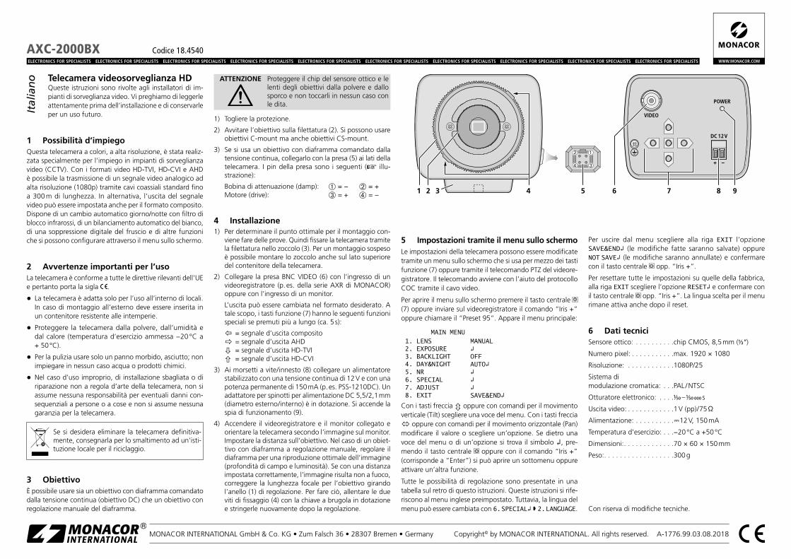
1) Togliere la protezione.
2) Avvitare l’obiettivo sulla filettatura (2). Si possono usare obiettivi C-mount ma anche obiettivi CS-mount.
3) Se si usa un obiettivo con diaframma comandato dalla tensione continua, collegarlo con la presa (5) ai lati della telecamera. I pin della presa sono i seguenti ( illu-strazione):
Bobina di attenuazione (damp): ➀ = − ➁ = +Motore (drive): ➂ = + ➃ = −
4 Installazione1) Per determinare il punto ottimale per il montaggio con-
viene fare delle prove. Quindi fissare la telecamera tramite la filettatura nello zoccolo (3). Per un montaggio sospeso è possibile montare lo zoccolo anche sul lato superiore del contenitore della telecamera.
2) Collegare la presa BNC VIDEO (6) con l’ingresso di un videoregistratore (p. es. della serie AXR di MONACOR) oppure con l’ingresso di un monitor.
L’uscita può essere cambiata nel formato desiderato. A tale scopo, i tasti funzione (7) hanno le seguenti funzioni speciali se premuti più a lungo (ca. 5 s):
= segnale d’uscita composito = segnale d’uscita AHD = segnale d’uscita HD-TVI = segnale d’uscita HD-CVI
3) Ai morsetti a vite / innesto (8) collegare un alimentatore stabilizzato con una tensione continua di 12 V e con una potenza permanente di 150 mA (p. es. PSS-1210DC). Un adattatore per spinotti per alimentazione DC 5,5 / 2,1 mm (diametro esterno / interno) è in dotazione. Si accende la spia di funzionamento (9).
4) Accendere il videoregistratore e il monitor collegato e orientare la telecamera secondo l’immagine sul monitor. Impostare la distanza sull’obiettivo. Nel caso di un obiet-tivo con diaframma a regolazione manuale, regolare il diaframma per una riproduzione ottimale dell’immagine (profondità di campo e luminosità). Se con una distanza impostata correttamente, l’immagine risulta non a fuoco, correggere la lunghezza focale per l’obiettivo girando l’anello (1) di regolazione. Per fare ciò, allentare le due viti di fissaggio (4) con la chiave a brugola in dotazione e stringerle nuovamente dopo la regolazione.
5 Impostazioni tramite il menu sullo schermoLe impostazioni della telecamera possono essere modificate tramite un menu sullo schermo che si usa per mezzo dei tasti funzione (7) oppure tramite il telecomando PTZ del videore-gistratore. Il telecomando avviene con l’aiuto del protocollo COC tramite il cavo video.
Per aprire il menu sullo schermo premere il tasto centrale (7) oppure inviare sul videoregistratore il comando “Iris +” oppure chiamare il “Preset 95”. Appare il menu principale:
MAIN MENU1. LENS MANUAL2. EXPOSURE 3. BACKLIGHT OFF4. DAY&NIGHT AUTO5. NR 6. SPECIAL 7. ADJUST 8. EXIT SAVE&END
Con i tasti freccia oppure con comandi per il movimento verticale (Tilt) scegliere una voce del menu. Con i tasti freccia oppure con comandi per il movimento orizzontale (Pan) modificare il valore o scegliere un’opzione. Se dietro una voce del menu o di un’opzione si trova il simbolo , pre-mendo il tasto centrale oppure con il comando “Iris +” (corrisponde a “Enter”) si può aprire un sottomenu oppure attivare un’altra funzione.
Tutte le possibilità di regolazione sono presentate in una tabella sul retro di questo istruzioni. Queste istruzioni si rife-riscono al menu inglese preimpostato. Tuttavia, la lingua del menu può essere cambiata con 6. SPECIAL 2. LANGUAGE.
Per uscire dal menu scegliere alla riga EXIT l’opzione SAVE&END (le modifiche fatte saranno salvate) oppure NOT SAVE (le modifiche saranno annullate) e confermare con il tasto centrale opp. “Iris +”.
Per resettare tutte le impostazioni su quelle della fabbrica, alla riga EXIT scegliere l’opzione RESET e confermare con il tasto centrale opp. “Iris +”. La lingua scelta per il menu rimane attiva anche dopo il reset.
6 Dati tecniciSensore ottico: . . . . . . . . . .chip CMOS, 8,5 mm (1⁄3 ”)
Numero pixel: . . . . . . . . . . .max. 1920 × 1080
Risoluzione: . . . . . . . . . . . .1080P/25
Sistema di modulazione cromatica: . . .PAL / NTSC
Otturatore elettronico: . . . .1⁄50 – 1⁄50 000 s
Uscita video: . . . . . . . . . . . .1 V (pp) / 75 Ω
Alimentazione: . . . . . . . . . .12 V, 150 mA
Temperatura d’esercizio: . . .−20 °C a +50 °C
Dimensioni: . . . . . . . . . . . . .70 × 60 × 150 mm
Peso: . . . . . . . . . . . . . . . . . .300 g
Con riserva di modifiche tecniche.
Italiano

Riga del menu Scelta / Sottomenu Impostazione; funzione
1. LENS – Obiettivo
MANUAL Diaframma fisso
DC diaframma comandato
1. MODE
INDOOR Campo d’impiego: uso interno
OUTDOOR
1. MIN SHU. 1/25 = Esposizione max. [s] per uso esterno2. MAX SHU. 1⁄50, FLK (= 1⁄100), 1/200 … 1⁄50 000 = Esposizione min. [s] per uso esterno
3. RETURN *RET = Ritorno a un livello superiore del menuSAVE&END = Salvare le modifiche e uscire dal menu
2. IRIS SPEED 0 … 8 … 15 = Velocità per il comando del diaframma
2. EXPOSURE – Esposizione
1. SHUTTERAUTO = esposizione automatica1/25, 1⁄50, FLK (= 1⁄100), 1/200 … 1⁄50 000, x 2, x 4 … x 30 = tempo fisso dell’otturatore [s]
2. AGC 0 … 15 = settore di regolazione gain (0 = nessuna regolazione gain)
3. SENS-UPOFF Aumento dell’esposizione disattivato con luce debole
AUTO 1. SENS-UP x 2 … x 30 = Aumento dell’esposizione con luce debole 1
4. BRIGHTNESS 1 … 65 … 100 = Luminosità dell’immagine
5. D-WDR
OFF Aumento della dinamicità disattivato
ON 1. LEVEL 0 … 8 = Grado dell’aumento della dinamicità
AUTO Grado dell’aumento della dinamicità determinato automaticamente
3. BACKLIGHT – Compensazione della controluce
OFF Nessuna compensazione della controluce
BLC Schiarimento di settori
1. LEVEL LOW, MIDDLE, HIGH – Grado dello schiarimento
2. AREA Impostazione del settore da schiarire 2
3. DEFAULT Resetta tutte le impostazioni del sottomenu alle impostazioni della fabbrica
HSBLC Annerimento delle parti più chiare
1. SELECT AREA 1 … 4 – scegliere il settore da impostare
2. DISPLAYON Impostare e attivare il settore scelto 2
OFF Disattivare il settore scelto
3. BLACK MASK ON, OFF – Annerimento delle parti più chiare on /off
4. LEVEL 1 … 50 … 100 = valore soglia per l’annerimento delle parti più chiare
5. MODEALL DAY HSBLC sempre attivo
NIGHT 1. AGC LEVEL 0 … 48 … 255 = valore soglia (HSBLC attivo solo con luce debole)
6. DEFAULT Resetta tutte le impostazioni del sottomenu alle impostazioni della fabbrica
WDR Aumento della dinamicità
1. LEVEL 0 … 4 = Grado dell’aumento della dinamicità
2. D&N MODE OFF, AUTO – Aumento della dinamicità on /off
4. DAY&NIGHT – Funzionamento giorno /notte (Cambio fra funzionamento a colori e b /n)
EXT – Commutazione tramite sensore luminosità
1. D N (DELAY) 0 … 3 … 60 = Ritardo per commutazione automatica giorno notte
2. N D (DELAY) 0 … 3 … 60 = Ritardo per commutazione automatica notte giorno
AUTO – Commutazione tramite luminosità immagine
1. D N (AGC) 1 … 250 … 255 = Valore soglia per commutazione giorno notte
2. D N (DELAY) 0 … 5 … 60 = Ritardo per commutazione automatica giorno notte
3. N D (AGC) 1 … 170 … 255 = Valore soglia per commutazione notte giorno
4. N D (DELAY) 0 … 5 … 60 = Ritardo per commutazione automatica notte giorno
COLOR – Funzionamento a colori
B / W Funzionamento b /n
1. BURSTON, OFF – Segnale sincronia cromatica (solo se necessario per sincronizzazione del
monitor)
2. IR SMART
ON 1. LEVEL 0, 1 … 15 = compensa da vicino la sovresposizione per via dei LED IR
2. AREA Impostazione del relativo settore 2
OFF Funzione disattivata
5. NR – Soppressione rumore1. 2DNR OFF, LOW, MIDDLE, HIGH – Soppressione rumore 2D (off, bassa, media, alta)
2. 3DNR OFF, LOW, MIDDLE, HIGH – Soppressione rumore 3D (off, bassa, media, alta)
Riga del menu Scelta / Sottomenu Impostazione; funzione
6. SPECIAL – Funzioni particolari
1. D-EFFECT
1. FREEZE ON, OFF – “Freezing” dell’immagine (immagine ferma)
2. MIRROR MIRROR, V-FLIP, ROTATE, OFF – rispecchiare o roteare in senso orizzontale /verticale
3. NEG. IMAGE ON, OFF – Immagine negativa
2. LANGUAGE – Lingua del menu ENG, GER, FRA, ITA, SPA, POL, RUS, POR, NED , TUR , HEB , ARB , …
3. DEFECT Riconoscimen-to e compen-sazione di pixel difettosi del sensore
1. LIVE DPC
OFF Riconoscimento automatico, permanente di errori dei pixel disattivato
ON 1. AGC LEVEL 0 … 128 … 255 = Valore soglia AGC
2. LEVEL 0 … 14 … 100 = Sensibilità
2. WHITE DPC
OFF Riconoscimento semiautomatico di pixel sempre chiari disattivato
ON
1. POS / SIZE Impostazione del relativo settore 2
2. START Start del riconoscimento automatico di pixel sempre chiari
3. DPC VIEW ON, OFF – Immagine nera (per vedere meglio gli errori di pixel)
4. LEVEL 0 … 13 … 100 = Sensibilità
5. AGC 0 … 14 = Valore soglia AGC
6. SENS-UP x 2 … x 6 … x 30 = Aumento dell’esposizione
3. BLACK DPC
OFF Riconoscimento semiautomatico di pixel sempre scuri disattivato
ON
1. POS / SIZE Impostazione del relativo settore 2
2. START Start del riconoscimento semiautomatico di pixel sempre scuri
3. DPC VIEW ON, OFF – Immagine bianca (per vedere meglio gli errori di pixel)
4. LEVEL 0 … 95 … 100 = Sensibilità
7. ADJUST – Adattamento
1. SHARPNESSAUTO
1. LEVEL 0 … 5 … 10 = Grado della correzione della nitidezza dell’immagine
2. START AGC 0 … 64 … 255 = Valore d’avvio per la correzione della nitidezza dell’immagine
3. END AGC 0 … 160 … 255 = Valore finale per la correzione della nitidezza dell’immagine
OFF Correzione della nitidezza dell’immagine automatica disattivata
2. MONITOR
1. GAMMA USER, 0.45, 0.50, 0.55 … 1.00 = Esponente per la correzione del gamma
2. BLUE GAIN 0 … 52 … 100 = Correzione cromatica componente blu
3. RED GAIN 0 … 52 … 100 = Correzione cromatica componente rosso
3. LSC ON, OFF – Correzione della perdita di luminosità ai margini dell’immagine
4. MONITOR OUT
THD (= TVI)
Formato del segnale videoCHD (= CVI)
CVBS AHD
5. VIDEO OUT. PAL, NTSC; non cambiare (possibile perdita dell’immagine)!
8. EXIT
SAVE&END Uscita dal menu sullo schermo e salvare le modifiche
RESET Resettare le modifiche alle impostazioni della fabbrica (senza salvataggio)
NOT SAVE Uscita dal menu sullo schermo e annullare le modifiche
Opzioni in grassetto = Impostazioni della fabbrica *La riga RETURN con le opzioni RET e SAVE&END è presente in tutti i sottomenu.1disponibile solo se per EXPOSURE \ SHUTTER è stato scelto = AUTO o 1/25 e EXPOSURE \ AGC > 02 Per l’impostazione di un settore:
1) Con indicazione di POSITION, con , impostare la posizione del settore nell’immagine e confermare con o “IRIS +“.2) Con SIZE, con , impostare le dimensioni del settore e confermare con o “IRIS +“.3) Condecidere se l’impostazione deve terminare (RET) o se la posizione o le dimensioni devono ancora essere modificate (AGAIN) e confermare con
o “IRIS +“.