
AWIPS to Ingest Winter 2005 FAA’s TDWR Data What’s Inside? · mation from several types of...
20
N ow NEXRAD In the late 1990s, the National Weather Service (NWS) began a joint venture with the Federal Aviation Administration (FAA) to explore the feasibility of using weather radar infor- mation from several types of opera- tional FAA radars. Benefits to the NWS by using FAA weather radar data to complement Weather Surveillance Radar – 1988 Doppler (WSR-88D) data were identi- fied as follows and plans were formed: • Backup data during WSR-88D out- ages, • Low-altitude information at longer ranges of the WSR-88D, • Improved coverage in the WSR-88D cone of silence, • Data in areas of incomplete WSR- 88D coverage (e.g., where there is beam blockage or ground clutter), • Different viewing perspectives on storms to better sample radial veloc- ity maxima and storm morphology, • Improved quality control of WSR- 88D data for such problems as anom- alous propagation, • Potential mitigation of obscuration of storms due to range folded echoes • Improved “best information” mosa- ics, • Improved precipitation estimates, • Facilitate multiple Doppler analyses to provide rectilinear wind fields. The NWS continues to collaborate with the FAA on projects to ingest data from several FAA radars: Terminal Doppler Weather Radar (TDWR), Air Route Surveillance Radar – Model 4 (ARSR-4) and Airport Surveillance Radar – Model 11 (ASR-11). The NWS Office of Science and Technol- ogy (OST) developed World-Wide Web server systems which have generated product images from these FAA radars and provided products to selected Weather Forecast Offices (WFOs) for the past four years. The NWS has demonstrated that weather data from FAA radars could complement the WSR-88D network. Recent progress using data from these systems varies by radar. The FAA has implemented changes to the ARSR- 4 to improve the detection of low alti- tude weather. The ASR-11 in Erie, PA was accepted by the FAA and the proof- of-concept demonstration was begun. The new Linux-based TDWR Web server was deployed to additional sites. Most significantly, the NWS will nationally deploy the TDWR Supple- mental Product Generator (SPG) to pro- vide TDWR data into the Advanced Weather Interactive Processing System (AWIPS) in a way that allows it to be displayed and fully integrated along with WSR-88D and other weather data. (Continued on Page 2) AWIPS to Ingest FAA’s TDWR Data Winter 2005 What’s Inside? Issue 14 Page 5 Benjamin Franklin & Dr. Van de Graff Would Have Been Amused Page 6 On the Comms Front... Page 8 You Wanted to Know... Page 9 VCP 121 and the Multi-PRF Dealiasing Algorithm Page 15 Developing an AWIPS Flash Flood Procedure “Bundle” Page 16 - Identifying the Cause of WSR-88D Ghost Echoes - New ROC Deputy Director Page 17 New Electric Hoist Lifts Loads Into Radome Page 18 - Multidisciplinary Approach to WSR-88D Data Quality Assurance - Award Winning Staff Page 19 Vogt Named ROC Director Page 20 Level II Data Collection Update
-
Upload
nguyentruc -
Category
Documents
-
view
213 -
download
0
Transcript of AWIPS to Ingest Winter 2005 FAA’s TDWR Data What’s Inside? · mation from several types of...

Now NEXRAD
In the late 1990s, the National Weather Service (NWS) began a joint venture with the Federal Aviation Administration (FAA) to explore the feasibility of using weather radar infor-mation from several types of opera-tional FAA radars.
Benefits to the NWS by using FAA weather radar data to complement Weather Surveillance Radar – 1988 Doppler (WSR-88D) data were identi-fied as follows and plans were formed:• Backup data during WSR-88D out-
ages,• Low-altitude information at longer
ranges of the WSR-88D,• Improved coverage in the WSR-88D
cone of silence,• Data in areas of incomplete WSR-
88D coverage (e.g., where there is beam blockage or ground clutter),
• Different viewing perspectives on storms to better sample radial veloc-ity maxima and storm morphology,
• Improved quality control of WSR-88D data for such problems as anom-alous propagation,
• Potential mitigation of obscuration of storms due to range folded echoes
• Improved “best information” mosa-ics,
• Improved precipitation estimates,• Facilitate multiple Doppler analyses
to provide rectilinear wind fields.
The NWS continues to collaborate with the FAA on projects to ingest data from several FAA radars: Terminal Doppler Weather Radar (TDWR), Air Route Surveillance Radar – Model 4 (ARSR-4) and Airport Surveillance Radar – Model 11 (ASR-11). The NWS Office of Science and Technol-ogy (OST) developed World-Wide Web server systems which have generated product images from these FAA radars and provided products to selected Weather Forecast Offices (WFOs) for the past four years. The NWS has demonstrated that weather data from FAA radars could complement the WSR-88D network.
Recent progress using data from these systems varies by radar. The FAA has implemented changes to the ARSR-4 to improve the detection of low alti-tude weather. The ASR-11 in Erie, PA was accepted by the FAA and the proof-of-concept demonstration was begun. The new Linux-based TDWR Web server was deployed to additional sites. Most significantly, the NWS will nationally deploy the TDWR Supple-mental Product Generator (SPG) to pro-vide TDWR data into the Advanced Weather Interactive Processing System (AWIPS) in a way that allows it to be displayed and fully integrated along with WSR-88D and other weather data.
(Continued on Page 2)
AWIPS to Ingest FAA’s TDWR Data
Winter 2005
What’s Inside?
Issue 14
Page 5 Benjamin Franklin & Dr. Van de Graff Would Have Been Amused
Page 6On the Comms Front...
Page 8You Wanted to Know...
Page 9VCP 121 and the Multi-PRF Dealiasing Algorithm
Page 15 Developing an AWIPS Flash Flood Procedure “Bundle”
Page 16- Identifying the Cause of
WSR-88D Ghost Echoes
- New ROC Deputy Director
Page 17New Electric Hoist Lifts Loads Into Radome
Page 18- Multidisciplinary
Approach to WSR-88D Data Quality Assurance
- Award Winning Staff
Page 19Vogt Named ROC Director
Page 20Level II Data Collection Update

page 2
Now NEXRAD
(Continued from Page 1)
Deployment will begin will begin in the spring of 2005 in conjunction with AWIPS Operational Build 5 (OB5) software.TDWR
The FAA operates 45 TDWRs near many of the largest U.S. airports (see Figure 1). These C-band
Doppler weather radars provide data similar to the WSR-88D, but at higher spatial and temporal resolu-tion and with different antenna scan strategies. The TDWR automatically changes between two main scan modes, Monitor mode and Hazardous mode, when TDWR algorithms detect a potential hazard near its associated airport. In both modes the scan
pattern begins with a long-range (248 nautical mile-nmi), low pulse repetition frequency (PRF), reflectiv-ity-only scan which is used by TDWR algorithms to flag multiple trip echoes. The remaining scans pro-vide reflectivity and Doppler data to the normal (short) range (48 nmi) of the TDWR. In Monitor mode, after the initial three low level scans, the eleva-tion angle consistently increases up to a maximum angle of 60 degrees. However, in the Hazardous mode the TDWR makes a low elevation scan (less than one degree) once per minute and repeats a sequence of aloft scans every three minutes. Figure 2 shows the Hazardous mode scan pattern for the Balti-more-Washington International airport (BWI) TDWR.
The TDWR provides reflectivity and Doppler base data at a resolution of one degree azimuth by 150 meters in range. However, the range resolution at the long range, low PRF scan, is 300 meters. TDWR Web Server
To demonstrate the utility of TDWR data at WFOs, the NWS OST-developed Web server ingests TDWR base data to generate image files which are viewable from a Web browser. In 2003, the Web server was ported from Solaris to a PC-based Linux platform and enhanced as described by Stern (2004). It is currently in use at the Sterling, VA, Salt Lake City, UT, Phoenix, AZ, Las Vegas, NV, and Green-ville-Spartanburg, SC WFOs. The Web server pro-vides reflectivity and velocity base data images for several elevation angles, looping, zoom, cursor read-out, and 31-day archive of image files. The user interface is available directly at the Web server and also from the AWIPS Netscape browser, if the Web server is located within the AWIPS network.
A potential new use was found for the TDWR Web server during the onslaught of hurricanes in Flor-ida during 2004. As Hurricane Frances approached Florida, it appeared that the Miami WSR-88D would not be repaired in time after being damaged by an ear-lier lightning strike. Emergency plans to send a fully customized Web server to the Miami WFO and use a South Florida TDWR as backup were implemented.
(Continued on Page 3)
TDWR (Cont.)
Figure 2: TDWR Hazardous Mode Scan
Figure 1: TDWR Site Locations

page 3
Now NEXRAD
(Continued from Page 2)
Shipping of the system was halted at the last minute when personnel in Miami indicated that the WSR-88D would be operational for the landfall.
With the visibility of this new capability, until TDWR SPG is fully deployed, the NEXRAD RadarOperations Center (ROC) has subsequently beguncompiling plans, equipment and procedures so that customized TDWR Web servers could be quickly sent to a WFO in the event of a failure to a WSR-88D.SPG System Development
The TDWR SPG ingests TDWR base data and generates products following WSR-88D Interface Control Document (ICD) formats. Using the Com-mon Operations and Development Environment (CODE), WSR-88D Open Radar Products Generator (ORPG) software was used to develop the SPG. The intent of the SPG is to generate and provide products to AWIPS for display and integration with other weather data. Since the SPG provides products to AWIPS in the same method and format as products are currently provided from the WSR-88D, many of the capabilities available in AWIPS D2D for WSR-88D products will be available for TDWR SPG prod-ucts. Initially, the SPG will just provide TDWR base products. However, additional algorithms and prod-ucts will be incorporated in subsequent SPG software builds
The NWS has approved the TDWR SPG system for operational development. AWIPS software changes required for the TDWR SPG are included in AWIPS OB5. Beta testing of SPG is scheduled to begin in March 2005 with full deployment beginning in May 2005 and continuing through September 2006.
The NWS will develop and deploy TDWR SPG systems to WFOs. Once the deployment has com-pleted, Operations and Maintenance (O&M) of SPG systems will be transferred to the ROC, a tri-agency (NWS, FAA, and Department of Defense-DoD) orga-nization with support costs to be provided by NWS.SPG System Architecture
The SPG system consists of ORPG software that is tailored to characteristics of the TDWR, a little-
endian PC processor, the Linux operating system, and T1 ingest communications equipment. The SPG sys-tem will be on the AWIPS Local Area Network (LAN). The SPG was developed using Linux CODE which was based on the official source code release of WSR-88D RPG Build 6. The SPG will be installed in a standalone cabinet, using an AWIPS equipment rack. The rack space will become available as a by-product of the AWIPS DX server upgrade.TDWR and WFO Sites
SPGs will be deployed to WFOs which have TDWR radars within their County Warning Area (CWA). The 45 operational TDWRs will be provided to 34 WFOs. Multiple TDWR SPG systems will be provided to WFOs where the CWA includes more than one TDWR (e.g., Washington D.C., Miami, New York City, Chicago, and others). Initially, SPG prod-ucts will only be available to the associated WFO. However, repeating multiple one-time product requests (RMR) from a non-associated WFO will be provided in a subsequent software release.Products and Capabilities
The SPG will provide base reflectivity, velocity, and spectrum width products in both standard (4-bit) and full resolution (8-bit) format. The spatial and temporal resolution of the TDWR data is preserved in the SPG products. That is, the shorter range scans contain a resolution of 150 meters per gate while the long range reflectivity-only scan has a resolution of 300 meters. To take advantage of the 80 meter/second velocity threshold of the TDWR, SPG-generated velocity products will use a one meter/second resolu-tion. The typical value used in the WSR-88D is a half meter/second resolution.
Within the six-minute hazardous mode scan pat-tern, time stamps of the base data products will vary to distinguish between the repeating scans at the same elevation angle. In figure 2, this is represented by the color of the dots which represent the hazardous mode elevation scans. Products at scans having the same color will have the same time stamp and time will increase by one-minute for each new color.
The AWIPS capabilities for SPG TDWR products (Continued on Page 4)
TDWR (Cont.)

page 4
Now NEXRAD
TDWR (Cont.)(Continued from Page 3)
are consistent with those provided for WSR-88D products but simpler because of the reduced product suite. The capabilities include routine and one-time product request, zoom, data sampling, image com-bine/fade, time and all-tilt loops, TDWR and WSR-88D mosaic, storm relative velocity, VR shear, and local AWIPS archive. Fig-ures 3, 4, and 5 provide examples of TDWR SPG products dis-played on AWIPS D2D.Future Plans
The capabilities described above pro-vide a foundation for future growth. Algo-rithm and products which may be easily adapted to TDWR data include composite reflectivity, VIL and VAD algorithms. Areas that require more significant effort to optimize the NEXRAD algorithms to the TDWR data res-olution include stormcell identification and tracking, mesocyclone and tornadic vortex
(Continued on Page 5)
Figure 3: AWIPS D2D 8-bit mosaic of WSR-88D and Long Range TDWR Reflectivity (in the main panel). The small panels contain Reflectivity of the same storm viewed separately by WSR-88D and TDWR.
Figure 4: Magnified 8-bit TDWR Base Velocity Product (in the main panel). The small panels contain Base Velocity of the same storm viewed separately by WSR-88D and TDWR.

page 5
Now NEXRAD
(Continued from Page 4)
detection, and rain-fall accumulation. Additional possible enhancements include adapting AWIPS SCAN to TDWR products, central collection of products and/or base data, and multiple Doppler radar algo-rithms.
In 2005, the NWS will begin deploying the SPG system, which when combined with AWIPS OB5 will provide to NWS forecasters TDWR data which is fully integrated with other weather data and the full suite of AWIPS user capabilities.
This article is excerpted from:Istok, M., P. Pickard, R. Okulski, R. Saffle, and
W. Bumgarner, 2005: NWS Use of FAA Radar Data - Progress and Plans, 21st Conf. on Interactive Information and Processing Systems, San Diego, CA, Amer. Meteor. Soc., 5.3
TDWR (Cont.)
Figure 5: Magnified 8-bit Storm Reflectivity TDWR Velocity Product (in the main panel). The small panels contain TDWR base reflectivity and velocity of the same storm (data from 17 Sept 20042230Z).
Benjamin Franklin and Dr. Van de Graff would have been amused. Under ideal conditions, the WSR-88D radome in Marquette, Michigan, proved to be an exemplary model of a static-electric generator, a sub-ject that was near- and-dear to these two scientists. A video of this event taken inside and looking toward the apex of the darkened radome can be viewed at http://www.roc.noaa.gov/news/other/Radome_sparks.wmv.
On this day, unusually large and very cold (dry) snow flakes were falling and sliding off the radome at a remarkable rate. The adhesion of the sliding snow-flakes across the composite radome panels allowed a significant charge to build. Heated, moist air rising
inside the radome meeting the charged outer surface at the panel junctions was all it took to lower the resis-tance and complete the circuit. During peak observed snowfall periods, the rate of static discharges was noted to be several per second.
Turning off the heaters and allowing the interior of the radome to cool and the relative humidity to decrease at first reduced and then eliminated the dis-charges. Subsequent attempts at observing this tri-boelectric phenomenon involving smaller/wetter snowflake events were unsuccessful.
Jack RiceWFO Marquette, MI
Benjamin Franklin & Dr. Van de Graff Would Have Been Amused

page 6
Now NEXRAD
Figure 1: Scheduled Frame Relay/LAN-to-LAN connections.
FALL 2004 ACTIVATIONSNumber DoD WSR-88D Location NWS AWIPS Location1 KDOX - Dover AFB, MD PHI - Mount Holly, NJ2 KTYX - Ft Drum, NY BUF - Buffalo, NY3 KGWX - Columbus AFB, MS BMX - Birmingham, AL4 KGWX - Columbus AFB, MS HUN - Huntsville, AL5 KGWX - Columbus AFB, MS MEG - Memphis, TN6 KEVX - Eglin AFB, FL TAE - Tallahassee, FL7 KDYX - Dyess AFB, TX FWD - Fort Worth, TX
On the Comms Front...In NEXRAD Now Issue 13, we provided back-
ground on the first phase of Department of Defense (DoD) and Federal Aviation Administration (FAA) WSR-88D to NWS Advanced Weather Interactive Pro-cessing System (AWIPS) frame relay and LAN-to-LAN activations. Through the months of October and November 2004, seven additional DoD to NWS AWIPS
analog connections were transitioned to frame relay/LAN-to-LAN.
Figure 1 shows the frame relay/LAN-to-LAN con-nections completed this year and those scheduled for completion in early 2005.
AWIPS Patch or Other Modification Note 26 was (Continued on Page 7)

page 7
Now NEXRAD
(Continued from Page 6)
released the last week of October 2004 instructing all NWS offices to transition AWIPS systems from X.25 dial one time request (OTR) operations to TCP/IP based one time request operations (WAN OTR). WAN OTR became possible with RPG Build 5.0 and AWIPS Oper-ational Build 3, and was extended to DoD and FAA WSR-88Ds as frame relay/LAN-to-LAN connections to NWS AWIPS were established last summer. With AWIPS’ shift to WAN OTR operations, preliminary activities are underway to reduce the number of dial
lines on each RPG and the number of AWIPS dial-out lines supported on each AWIPS system.
Consolidation of commercial wideband T1 circuits with MCI telecommunications has ensued. The first of 31 locations transitioning to a new MCI provided wide-band occurred the last week of October 2004. It is pro-jected the delivery of the remaining 30 T1s will extend into early 2005.
The Air Force WSR-88D program has requested approximately 60 of the remaining legacy PUPs still in service at Air Force locations be converted to Small
(Continued on Page 8)
Comms (Cont.)EARLY 2005 ACTIVATIONS
Number2005
Projected Schedule
WSR-88D Location NWS AWIPS Location
8 TBD KHDX - Holloman AFB, NM EPZ - El Paso, TX9 TBD PGUA - Andersen AFB, Guam GUM - Guam10 1/17/05 ROC Test Bed NGIT AWIPS Test Bed11** 1/26/05 FSL AWIPS KFTG - Denver, CO12 2/16/05 KICX - Cedar City, UT FGZ - Flagstaff, AZ13 2/22/05 KAMX - Miami, FL EYW - Key West, FL14 2/23/05 KBYX - Key West, FL MFL - Miami, FL15 3/2/05 KBUF - Buffalo, NY CLE - Cleveland, OKH16 3/14/05 KHTX - Northeast Alabama OHX - Nashville, TN17 3/15/05 KHTX - Northeast Alabama MRX - Morristown, TN18 3/16/05 KHTX - Northeast Alabama BMX - Birmingham, AL19 3/17/05 KPAH - Paducah, KY LMK - Louisville, KY20 3/17/05 KLVX - Louisville, KY PAH - Paducah, KY21 3/23/05 KGJX - Grand Junction, CO SLC - Salt Lake City, UT22 3/30/05 KMOB - Mobile, AL JAN - Jackson, MS23 4/1/05 KLWX - Sterling, VA CTP - State College, PA24 4/5/05 KLZK - Little Rock, AR SHV - Shreveport, LA25 4/12/05 KSOX - Santa Ana Mountains, CA LOX - Oxnard, CA26 4/26/05 KSRX - Fort Smith, AR LZK - Little Rock, AR27 4/28/05 KHGX - Houston, TX SMG - Johnson Space Flight, Houston, TX28 4/28/05 KMLB - Melbourne, FL SMG - Johnson Space Flight, Houston, TX29 4/28/05 KEYX - Edwards AFB, CA SMG - Johnson Space Flight, Houston, TX30 4/28/05 KHDX - Holloman AFB, NM SMG - Johnson Space Flight, Houston, TX31 TBD KSFX- Pocatello, ID SLC - Salt Lake City, UT** LAN-to-LAN connection.

page 8
Now NEXRAD
(Continued from Page 7)
OPUP systems. The change request asks that the retrofit be spread across a six month period beginning in December 2005.
The Navy has informed the ROC that changes in Navy/Marine operational requirements and the avail-ability of WSR-88D data via the Internet permits their removal of X.25 dial lines from most RPGs. Discon-nect orders for Navy RPG dial lines have started to be processed. Upon final receipt and confirmation that the dial lines have been disconnected, field offices will be asked to download updated WSR-88D Communication Documentation from the ROC web page showing the removal of the Navy dial line. Once Navy dial lines are removed from RPGs, Navy/Marine OPUPs will be slated for removal from RPG Authorized “Dial-In” user lists with the deployment of RPG Build 8.0.
The FAA established new Microprocessor En Route Automated Radar Tracking System (MEARTS) con-nections between Ft. Polk, LA (KPOE) and the Ft Polk Air Traffic Terminal Radar Control (TRACON) and between San Juan, PR (TJUA) and the FAA Combined Center/RAPCON (CERAP) at San Juan International Airport in the Fall of 2004. An additional MEARTS connection to Andersen AFB, Guam (PGUA) is pro-jected for sometime in 2005. (Visit http://www.faa.gov/aua/oceanicatc/index.cfm?content=microearts for back-ground material on Micro-EARTS).
FAA ITWS (Integrated Terminal Weather System) deployments and associations to WSR-88Ds continue in accordance with Modification Notes 59 and 69. A new Charlotte ITWS to Greer, SC (KGSP) connection was completed in 2004 and two new ITWS systems will be installed in 2005 at the Detroit TRACON, asso-ciated to Detroit, MI (KDTX), and Cincinnati Air Traf-fic Control, associated to Cincinnati, OH (KILN). Site Readiness Review activities for the new systems will start in early 2005, with the finished form systems expected to be operational around mid-Summer.
The Houston Weather Forecast Office (WFO) and Houston, TX (KHGX) RPG are relocating to a new office about 1/2 mile from their existing address. It is expected the RPG will be shut down and moved to the new address in February 2005. All WSR-88D telecom-munications (telecoms) must re-established at the new
address. Tri-agency telecommunications focal points have been advised of the move and are engaged in hav-ing new telecoms in place at the new address in advance of the move.
For the second consecutive year, a representative from the WSR-88D Hotline attended and provided a presentation segment for AWIPS NCF Operator radar proficiency cross-training at the NGIT training facility in early December 2004. The Hotline presentation emphasized RPG Build 5.0 and Build 6.0 communica-tions changes, the introduction of frame relay and LAN-to-LAN connections between DoD and FAA WSR-88Ds and AWIPS, and WAN OTR.
Mark AlbertellyROC Operations Branch
Comms (Cont.)
You Wanted to Know...We at the ROC receive many questions from the
field, which are answered on a one-on-one basis. We thought many of the questions would be of interest to a large number of our readers. Therefore, in an attempt to better server our readers, we will be including a question and answer section in each issue of NEXRAD Now.
Brian Hirsch, NWS Central Region, submitted the following questions concerning the WSR-88D dis-play on AWIPS: There is a focus on high impact events and yet we have a the VIL Max set to 80? I understand that a 100 VIL may not have significance on a particu-lar day, given the environment, but on most days it might be helpful to know if that 80 VIL is 80 or 100.
Brian, hailstorms can occur with large quantities of small/wet hail that aren't classified as severe. The highly reflective hail would drive up the values of par-tial VIL and so maximum reflectivity is initially capped at 56 dBZ. As a secondary precaution against the hail bias, the VIL is capped at 80 kg/(m*m). Please click the link to the Vertically Integrated Liquid Water Algorithm Description, Section 5.1 - Limitations.
There are two additional VIL calculations, Cell-based VIL and DVL. Cell-based VIL, calculated in
(Continued on Page 20)

page 9
Now NEXRAD
In March 2004, two new volume coverage patterns, VCP 12 and VCP 121, were fielded as part of the Open Systems Radar Product Generator (ORPG) Build 5 software release. The focus of this article is VCP 121 and the Multi-PRF Dealiasing Algorithm (MPDA). VCP 121 retains the same elevation angles as VCP 21 but collects extra scans of Doppler data at the lowest five elevation angles using different pulse repetition frequencies (PRFs). This scanning strategy provides the Doppler data required by the MPDA. The MPDA combines the velocity data from the different PRFs to reduce range folding and provide robust velocity dealiasing. The goal of this article is to provide opera-tional users insight into how the MPDA generates a velocity product.
This year’s active hurricane season provided staff at forecast offices along the Gulf Coast the opportunity to gain experience using VCP 121. The data for the example discussed below were collected on the Key West WSR-88D (KBYX) while Hurricane Charley
passed nearby. Figure 1 shows the 8-bit reflectivity products at 06:05Z and 17:07Z on August 13, 2004. As will be shown later, the strength of the echo in the clutter region strongly influences the maximum range at which velocity data can be dealiased.
Before describing the MPDA’s processing steps we discuss the scanning sequence for VCP 121 (see Table 1) as it is relevant to the discussion that follows. The table contains the elevation sweep number, elevation, waveforms used, PRF number, and the corresponding unambiguous range (range to end of first trip) and Nyquist velocity. At 0.5 and 1.5 degrees elevation, the MPDA acquires a surveillance scan followed by a con-tiguous Doppler scan using PRF 8 that has been range unfolded by the RDA. The next two scans use contigu-ous Doppler waveform with PRFs 6 and 4, respectively that have not been range unfolded. At 2.4 and 3.4 degrees, the MPDA collects one scan using the Batch waveform with PRF 8 followed by two scans using
(Continued on Page 10)
VCP 121 and the Multi-PRF Dealiasing Algorithm
Figure 1: Key West, FL WSR-88D 8-bit reflectivity image of Hurricane Charley at 06:05Z (left) and 17:07Z (right) on 13 August 2004 at 0.5 degrees elevation. Range rings are every 50 n mi. Note the difference in the signal strength over the radar between the images.

page 10
Now NEXRAD
RDASweep No.
Elevation(deg) Waveform
Doppler PRF No.
Typical Unambiguous Range (n mi)
Typical Nyquist Velocity (m/s)
1 0.5 Surveillance - -2 0.5 Contiguous Doppler with range unfolding 8 63 35.03 0.5 Contiguous Doppler without range unfolding 6 74 29.54 0.5 Contiguous Doppler without range unfolding 4 96 23.55 1.5 Surveillance -6 1.5 Contiguous Doppler with range unfolding 8 63 35.07 1.5 Contiguous Doppler without range unfolding 6 74 29.58 1.5 Contiguous Doppler without range unfolding 4 96 23.59 2.4 Batch 8 63 35.010 2.4 Contiguous Doppler without range unfolding 6 74 29.511 2.4 Contiguous Doppler without range unfolding 4 96 23.512 3.4 Batch 8 63 35.013 3.4 Contiguous Doppler without range unfolding 6 74 29.514 3.4 Contiguous Doppler without range unfolding 4 96 23.515 4.3 Batch 4 96 23.516 4.3 Contiguous Doppler without range unfolding 7 69 32.017 6.0 Contiguous Doppler without range unfolding 5 80 26.518 9.9 Contiguous Doppler without range unfolding 7 69 32.019 14.6 Contiguous Doppler without range unfolding 8 63 35.020 19.5 Contiguous Doppler without range unfolding 8 63 35.0
(Continued from Page 9)
PRFs 6 and 4. At 4.3 degrees elevation, the MPDA uses a Batch waveform with PRF 4 and one extra contiguous Doppler with PRF 7. Above 4.3 degrees MPDA uses the same sequence of waveforms as does the legacy VCP 21 and velocity dealiasing is done using the legacy Velocity Dealiasing Algo-rithm. The time to complete one volume scan of VCP 121 is under 5 minutes 30 seconds.
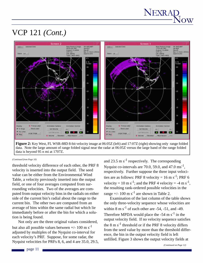
The MPDA first performs some housekeeping chores such as range unfolding the data collected using PRFs 6 and 4 and aligning azimuths from each Doppler scan. It then fills in the output velocity field with the range folded areas for which no velocity data are available. The two rules are based on con-sensus. Rule 1: If all three velocity input fields (PRFs 8, 6 and 4) have range folding in their bins at
the same azimuth and range then the output field’s bin at the same azimuth and range also is shown as range folded. Rule 2: If any two input velocity fields have range folding at the same azimuth and range and the third field has no data, the output velocity field’s bin at that azimuth and range is also indicated as range folded. Figure 2 shows the output velocity field with just the range-folded data inserted at both 06:05Z and 17:07Z.
Next, the MPDA examines data for which all three input fields have velocities at the same location. That is, it looks for a triple velocity solution. If the three velocities are within a threshold velocity differ-ence of each other (nominally 8 m s-1), the PRF 8 velocity is compared to a reference or seed velocity. If the seed and PRF 8 velocities are within another
(Continued on Page 11)
Table 1: Details of volume coverage pattern 121.
VCP 121 (Cont.)
page 11
Now NEXRAD
(Continued from Page 10)
threshold velocity difference of each other, the PRF 8 velocity is inserted into the output field. The seed value can be either from the Environmental Wind Table, a velocity previously inserted into the output field, or one of four averages computed from sur-rounding velocities. Two of the averages are com-puted from output velocity bins in the radials on either side of the current bin’s radial about the range to the current bin. The other two are computed from an average of bins within the same radial but which lie immediately before or after the bin for which a solu-tion is being found.
Not only are the three original values considered, but also all possible values between +/- 100 m s-1 adjusted by multiples of the Nyquist co-interval for each velocity’s PRF. Suppose, for some radar, the Nyquist velocities for PRFs 8, 6, and 4 are 35.0, 29.5,
and 23.5 m s-1 respectively. The corresponding Nyquist co-intervals are 70.0, 59.0, and 47.0 ms-1, respectively. Further suppose the three input veloci-ties are as follows: PRF 8 velocity = 16 m s-1; PRF 6 velocity = 10 m s-1; and the PRF 4 velocity = -4 m s-1, the resulting rank-ordered possible velocities in the range +/- 100 m s-1 are shown in Table 2.
Examination of the last column of the table shows the only three-velocity sequence whose velocities are within 8 m s-1 of each other are -54, -51, and -49. Therefore MPDA would place the -54 m s-1 in the output velocity field. If no velocity sequence satisfies the 8 m s-1 threshold or if the PRF 8 velocity differs from the seed value by more than the threshold differ-ence, the bin in the output velocity field is left unfilled. Figure 3 shows the output velocity fields at
(Continued on Page 12)
Figure 2: Key West, FL WSR-88D 8-bit velocity image at 06:05Z (left) and 17:07Z (right) showing only range folded data. Note the large amount of range folded signal near the radar at 06:05Z versus the large band of the range folded data is beyond 95 n mi at 1707Z.
VCP 121 (Cont.)

page 12
Now NEXRAD
(Continued from Page 11)
06:05Z and at 17:07Z with results after the first triple velocity pro-cessing. At 06:05Z velocity data have been inserted over a wide range of distances even as far as 125 n mi. However, at 17:07Z most of the data filled in are within the first trip for PRF 8 or only to about 63 n mi.
MPDA then attempts a second time to find a triple velocity solu-tion. This time all the velocities that lie between +/- 100 m s-1 plus the seed value are rank-ordered. If a sequence of velocities plus the seed velocity are within twice the original difference threshold (16 m s-1) of each other, the velocity for PRF 8 is inserted into the output velocity field. As there is little additional velocity data added with this step, it is not shown.
(Continued on Page 13)
PRF Input Velocity
Nyquist Co-interval Velocity Offset
Candidate Velocity (Input Velocity + Offset)
4 - 4 - 2 * 47 = - 94 - 986 10 - 2 * 59 = - 108 - 988 16 - 1 * 70 = - 70 - 544 - 4 - 1 * 47 = - 47 - 516 10 - 1 * 59 = - 59 - 494 - 4 0 * 47 = 0 - 46 10 0 * 59 = 0 108 16 0 * 70 = 0 164 - 4 1 * 47 = 47 436 10 1 * 59 = 59 698 16 1 * 70 = 70 864 - 4 2 * 47 = 94 90
Table 2: Example of potential velocities for a triple velocity solution.
Figure 3: Same as Figure 2 with the addition of velocity data after MPDA completes the first triplets solutions. At 06:05Z (left) there are velocity data over much of the image while at 17:07Z (right) most of the velocity data are within 63 n mi or the first trip for PRF 8. The eye is not yet clearly seen in either image.
VCP 121 (Cont.)

page 13
Now NEXRAD
(Continued from Page 12)
Next the MPDA tries to fill in bins in the output velocity field where there are only two input velocities available or for which no triple velocity solution could be found. This step is also called finding a pairs solu-tion. For each unfilled output velocity bin MPDA checks which pair of PRFs is available. It first checks to see if there is a PRF8 and PRF6 velocity pair. If both velocities exist, the two velocities must be within a threshold velocity difference (3 m s-1) or the veloci-ties resulting from adding or subtracting multiples of the Nyquist co-intervals must be within 3 m s-1. If a valid velocity is found, it must be within a threshold velocity difference of a seed value. The threshold velocity difference is computed as 80 percent of the smaller of the two Nyquist velocities. Next it checks for a PRF8 and PRF4 velocity pair. Lastly, it checks
for a PRF6 and PRF4 velocity pair. Figure 4 shows the output velocity fields for 06:05Z and 17:07Z after completing this step. At 06:05Z additional velocities are added at all ranges while at 17:07Z the largest addition to the output velocity field is between 63 and 74 n mi.
The MPDA then tries to fill in bins in the output velocity field for which only one velocity is available or for which no solution for velocity pairs from the previous step was found. The processing step is also referred to as the final attempts. MPDA runs this step twice, once without using the environmental wind table as a potential source for a seed velocity and a second time including the environmental wind table. After determining which input velocities are avail-able, the MPDA determines which velocity (or its value adjusted by multiples of its Nyquist co-interval)
(Continued on Page 14)
Figure 4: Same as Figure 3 with the addition of the second triplet solution and the pairs solutions. At 06:05Z (left) enough of the velocity data have been inserted to clearly identify the eye just beyond 100 n mi about 205 degrees azimuth. In fact, the image looks nearly complete. At 17:07Z (right) velocity data have been extended to 74 n mi but the eye is still not clearly defined.
VCP 121 (Cont.)

page 14
Now NEXRAD
(Continued from Page 13)
is closest to the seed value. The threshold velocity difference between the seed and the closest velocity must be less than 80 percent of the Nyquist velocity as in the preceding step. After completing the final attempts, the velocity images are largely completed. At 06:05Z (Figure 5, left) the remaining holes have been filled in while at 17:07Z (Figure 5, right) veloc-ities have been inserted between 74 and 95 n mi. Now at both times the eye is clearly discernable.
The last MPDA processing step fills in the remaining output velocity bins for which the previ-ous steps did not yield a solution. In this step, the MPDA first tries using logic similar to the previous step in generating an average of surrounding bins in the output velocity field for a seed value. If a good velocity cannot be found with that seed, MPDA next uses the Environmental Wind Table to provide a seed value. If that step fails too, MPDA puts into the out-
put velocity field the original input velocity. If more than one input velocity is available, the one acquired using the highest Nyquist velocity is put into the out-put velocity field. Because there are no major changes from the previous step, the results of this step are not shown.
After each of the major processing steps except the last described above, the MPDA performs three types of quality control checks. It first looks for out-liers in the output velocity field. It next checks for unreasonable discontinuities along radials. Finally, it looks for unreasonable discontinuities between radi-als. In the first and last quality control checks, veloc-ities that are suspect are removed forcing the MPDA to find a different solution. Radial discontinuities are corrected as they are found.
We hope, with this article, the operational com-munity will feel more comfortable using VCP 121.
(Continued on Page 15)
Figure 5: Same as Figure 4 with new velocity data after completing final attempts to insert data with single velocity estimates both without and with the sounding data. Note the images at both 06:05Z (left) and 17:07Z (right) are now essentially complete. The eye is now clearly discernible at 17:07Z.
VCP 121 (Cont.)

page 15
Now NEXRAD
As part of a strategy to better anticipate and issue warnings for flash flood events, a set of AWIPS pro-cedures incorporating NEXRAD radar data was developed for use by forecasters at NWSFO Grand Rapids, Michigan (GRR). A description of the proce-dures follows, focusing on the specific radar prod-ucts included.
The procedures are divided into two main groups. The first contains procedures for anticipating a heavy rain event, and includes mostly satellite and forecast model data. The second is for use immediately before and during the event. This group includes sev-eral radar procedures to assess the potential for slow moving or back-building storms, where the heaviest rainfall rates exist in relation to the local topography, and the potential for urban flooding is great. The list below describes the individual procedures. Local forecast offices can use this as a starting point, and develop customized procedures that best suit their forecast area’s hydrological concerns. The proce-dures are meant to augment the Flash Flood Monitor-ing and Prediction (FFMP) tools available in AWIPS.
List of NEXRAD Procedures • Local radar composite map• Local VAD Wind Profile• VAD wind Profiles from Upstream Radars• One Hour Precip (OHP), overlaid on Urban
Boundary map• 4 panel of One and Three Hour Precip (THP),
Storm Total Precip and Composite Reflectivity
The local composite radar loop gives the fore-caster “the big picture” of how the larger scale pre-cipitation is developing and propagating, including areas of heavier precipitation that could be moving towards the local forecast area. The VAD wind pro-files are used to confirm model and sounding data of environmental winds. This data is important in deter-mining storm motion and the potential for slow mov-ing and back-building storms. The OHP, overlaid on the Urban Boundary Map and run as a loop, is used
to monitor the potential for urban flooding. A local office study found urban flood events usually occur when rainfall rates over urban areas reach at least one half inch per hour and are maintained for two or more consecutive hours. The four-panel of One and Three Hour Precip, Storm Total Precip, and Compos-ite Reflectivity can be used with background maps of streams, roads, and topography. Along with FFMP, this can be used to keep track of potential problem areas for flooding along small streams or sub-basins as well as culverts and areas where steep topography could increase the chances for flash flooding and/or rapid rises along streams.
Again, the above list is suggested as a starting point for NEXRAD products, as each forecast area has specific flash flood concerns that need to be addressed. Procedures that include radar data can be combined with satellite and model data, along with observations and Local Analysis and Prediction Sys-tem/MAPS (Mesoscale Analysis and Prediction Sys-tem) Surface Analysis System (LAPS/MSAS) data to assess the many aspects of hydrology and meteorol-ogy important in flash flood anticipation and fore-casting. Feedback on these procedures is welcome at [email protected].
Ernest OstunoNEXRAD Focal PointNWS Grand Rapids, MI
(Continued from Page 14)
The Applications Branch intends to distribute a ques-tionnaire to the operational community in the near future to obtain feedback on both VCP 12 and VCP 121.
W. David ZittelROC Applications BranchTimothy WiegmanROC Applications Branch
Developing an AWIPS Flash Flood Procedure “Bundle”
VCP 121 (Cont.)

page 16
Now NEXRAD
During April 2004, staff at the Lubbock (KLBB) National Weather Service (NWS) Weather Forecast Office (WFO) were seeing bogus echoes in WSR-88D (Weather Surveillance Radar, 1988-Doppler) products. The Radar Operations Center (ROC) began an investigation to find the cause and to provide a solution. We called the false echoes “ghost echoes.”
From fields of meteorology, engineering, and electronics, a ROC troubleshooting team was assem-bled. The team examined KLBB products containing these false returns. We found ghost echoes were only produced from WSR-88D batch waveform. WSR-88D scanning strategies often utilize batch waveform for elevation angles above 1.65º and below 6º.
Batch waveform consists of a short series of long radar pulse intervals (Surveillance) followed by a longer series of short radar pulse intervals (Doppler).
Although later proven wrong, the first prevailing theory was that ghost echoes were somehow related to a new operational scanning strategy called Volume Coverage Pattern (VCP) 12. The Lubbock WSR-88D was one of the first sites to use VCP 12 opera-tionally. ROC staff reviewed playback of KLBB Archive Level II data and found ghost echoes seemed to only occur with batch cuts of VCP 12. However, we found no direct link between ghost echoes and VCP 12. The team considered other possible reasons for ghost echoes; those considerations included the newly installed Build 5 software for the Radar Prod-uct Generator (RPG) and components of some site-specific hardware.
A review of the WSR-88D Hotline database, cul-minating over a decade of records about WSR-88D field problems, yielded no similarities to the ghost echoes found at Lubbock. Since ghost echoes appeared to be a singular problem, team members were inclined to suspect a Lubbock hardware prob-lem. However, critical components at KLBB were soon found to be operable.
After an elusive search for the cause of ghost ech-oes, the team had compiled considerable information about the problem and the conditions required for ghost echoes to occur. A paper describing the ghost
Identifying the Cause of WSR-88D Ghost Echoesecho investigation will be presented at the American Meteorological Society Annual Meeting in January 2005. Click the following link to read the paper in its entirety: http://www.roc.noaa.gov/news/other/ghost_echoes8.pdf.
Randy SteadhamROC Applications BranchTony RayRSIS/ROC Operations Branch
New ROC Deputy DirectorTerry J. Clark was recently selected as deputy
director of the Radar Operations Center (ROC) in Norman, OK. Clark comes to the ROC, following his retirement from the U. S. Air Force (USAF), with a wealth of WSR-88D knowledge having established the Air Force Weather curriculum for the Next Gen-eration Weather Radar program.
Clark earned a Bachelor of Science degree in technical geography from South Dakota State Uni-versity in 1977, at which time he was commissioned in the USAF. In July 1984 he entered the Air Force Institute of Technology at Texas Technological Uni-versity at Lubbock, Texas and received a Master of Science degree in atmospheric science. He then served as a meteorology instructor, curriculum development officer and weather technician course supervisor at Chanute Technical Training Center, Chanute AFB, Illinois.
While stationed at Air Force Global Weather Central at Offutt AFB, Nebraska, Clark developed the center’s first worldwide deployable Theater Weather Center. He was appointed Chief of the Mis-sion-Tailored Products Branch, which provided spe-cialized environmental forecast products in support of the White House Military Office, National Com-mand Authority, the National Security Agency, and other governmental agencies.
Clark reached the rank of Lt Colonel and was selected as the operations officer for the 88th Opera-
(Continued on Page 17)

page 17
Now NEXRAD
New Electric Hoist Lifts Loads Into Radome
The principal intended use for the manual davit crane in the NEXRAD radome is to support the removal and replacement of equipment inside the ped-estal. However, the manual crane has also served as the only approved means for lifting loads from the ground into the radome. While the manual crane is well suited to support its pedestal maintenance role, it does not provide a practical means of lifting loads from the ground into the radome. As a result, the ROC will soon be providing electric davit cranes for all NWS and DOD sites through the deployment of a Modification Note/TCTO. This electric crane does not replace the manual davit crane for pedestal main-tenance procedures, but will provide a much easier means of hoisting equipment and supplies from the ground, into the radome. The electric davit crane, along with the included cargo bag is depicted in Figure 1.
The electric davit crane is certified to lift up to 400 pounds. The winch motor uses 110 VAC and is rated for continuous duty. An automatic brake engages to hold the load whenever no power is applied to the motor. The electric hoist mast fits into the existing
Figure 1: Electric hoist and cargo bag.
Deputy (Cont.)(Continued from Page 16)
tions Support Squadron at Wright-Patterson AFB, Ohio, which was responsible for daily flight opera-tions of the 47th Airlift Flight, airfield operations and air traffic control, and weather operations. He assumed additional responsibility when he was given command of the 88th Maintenance Squadron responsible for all flightline maintenance activity, the largest USAF precision measurement labora-tory, regional defense logistics activity, and a muni-tions storage facility.
In his final USAF assignment with the Air Force Weather Agency’s plans and programs directorate, Clark was responsible for the planning, program-ming, budgeting, and execution of an annual operat-ing budget of over $96 million and acquisition investment budget of over $60 million.
Clark has served as the military director of Day-ton, Ohio’s United States Air and Trade Show, and Air Force Museum WWI Fly-In. During his mili-tary service he received many decorations including the Air Force Meritorious Service Medal with six oak leaf clusters, Air Force Achievement Medal, and National Defense.
Ruth JacksonMETI/ROC Program Branch
davit socket next to the cargo hatch, without modifi-cation. The hoist is stowed in two pieces: the boom assembly and the mast. The boom assembly weighs 91 pounds and the mast weighs 26 pounds. Due to the weight of the hoist, two persons are required to install and stow it. The installation procedures in the Modification Note/TCTO and the hoist user’s manual fully illustrate the steps required to safely install and stow the crane. Each electric davit crane will arrive with a “Load Test Certificate” signifying that the crane has passed a 125% load test. Site maintenance personnel must retain this load certificate on file.
Don SanderRSIS/ROC Engineering Branch

page 18
Now NEXRAD
Award Winning Staff
Multidisciplinary Approach to WSR-88D Data Quality AssuranceThroughout 2004, Radar Operations Center (ROC)
personnel visited several radar sites to address data quality-related problems. Troubleshooting these real-time problems, while on site, allowed the ROC to learn a great deal. In an effort to share those findings, and to recognize the cooperative efforts of several NWS Regions and WFOs, the ROC elected to write a paper for the January 2005 American Meteorological Society Annual Meeting. The entire paper can be seen at: http://www.roc.noaa.gov/news/other/Data_Quality_Final.pdf.
In an effort to appeal to a wider audience, as well as provide a practical “roadmap” toward increasing WSR-88D data quality, a slightly different approach was taken in writing this paper. The authors include one meteorologist and two electronics technicians. They discuss each site visit from both technical and operational perspectives, pointing out those problems which are related to hardware, and those related to
selected adaptable parameters, and providing field-tested ideas explaining how field technicians and oper-ators can work through problems at their sites. The paper discusses three site visits, detailing procedures used and troubleshooting techniques incorporated, to resolve each site’s problems. Some problems dis-cussed include “hot/cold” radars, poor precipitation estimates from the WSR-88D, and poor clutter sup-pression. In concluding, the authors provide a list of “Lessons Learned” which are again, based on actual field experience.
Tony RayRSIS/ROC Operations BranchJimmy RoperROC Operations BranchBobby HarpROC Operations Branch
The WSR-88D program is staffed by dedicated professionals around the world. Here at the ROC we are proud of our employees, many of whom have been recognized for their outstanding work and com-mitment to excellence.
The ROC Employee of the Quarter (EOQ) and Team Member of the Quarter (TMOQ) Awards were established for the ROC Awards Program to recog-nize people who;
• Demonstrate exceptional performance• Exceed normal customer service• Perform a worthy non-duty related act • Accomplish a unique short-term project or spe-
cial assignment• Accomplish an office productivity and effi-
ciency enhancement of procedures• Produce an office morale enhancement through
teamwork. Winners of the ROC EOQ and TMOQ are pre-
sented with a framed certificate signed by the ROC Director and the winner’s name is engraved on a
plaque in the large conference room in the ROC South building and on a plaque in the lobby of the ROC North facility. Winners are also considered for NOAA Employee and Team Member of the Quarter and other awards.
The winner of the Employee of the Quarter for the third quarter fiscal year 2004 is Mark Fresch, a mete-orologist in the ROC Applications branch, and the winner for the Team Member of the Quarter is Eric Ice, an Administrative Assistant employed by RS Information Systems (RSIS).
Terrell “B” Ballard, an Electronics Technician and Team Lead in the ROC Operations branch is winner of the Employee of the Quarter for the fourth quarter fiscal year 2004, and the winner for the Team Mem-ber of the Quarter is Bobby Harp, an Electronics Technician employed by RSIS.
Mary CulleyROC Applications Branch

page 19
Now NEXRAD
Richard Vogt was recently appointed director of the National Oceanic and Atmospheric Administra-tion’s NEXRAD Radar Operations Center (ROC) in Norman, Okla. NOAA is an agency of the U.S. Department of Commerce.
The ROC provides centralized, life-cycle support to the national network of 166 WSR-88D NEXRAD radars located throughout the United States and selected international locations. These installations are operated by the United States Air Force, Federal Aviation Administration and NOAA’s National Weather Service.
Vogt is a meteorologist with 35 years of broad-ranging leadership experience with an emphasis in weather forecasting, radar meteorology, systems acquisition, life-cycle systems support and program management. He has served as the ROC’s deputy director since October 1993 and as acting director since May 2003. During this period, he also pro-vided leadership for the Headquarters Air Force Weather Agency (AFWA) contingent at the Radar Operations Center.
“Director of NOAA's Radar Operations Center is a key position in the front line defense of our nation against the effects of severe weather,” said retired Air Force Brig. Gen. David L. Johnson, director of NOAA's National Weather Service. “Rich's new position is one of increased responsibility with over-sight over Federal Aviation Administration and Department of Defense radar systems as well as those of the National Weather Service.”
A 25-year veteran of the U.S. Air Force, Vogt’s career has included executive-level experience as a colonel in a variety of key leadership positions. He has served in diverse locations throughout the United States, as well as in Korea, Japan and Germany. His military career culminated in an assignment as dep-uty director of weather at U.S. Air Force headquar-ters before his retirement from active duty in February 1993.
Vogt earned a Bachelor of Science degree in edu-cation and chemistry from Southwestern Oklahoma State University in 1967, and a Master of Science
degree in meteorology from Texas A & M University in 1972.
As ROC director, Vogt oversees a wide variety of critical support functions for the $1.2 billion NEXRAD network. The Center provides expert maintenance and operations assistance to resolve radar problems and outages via a 24-hour helpdesk and on-site maintenance. The ROC also conducts system engineering and software engineering projects to resolve system deficiencies and upgrade radar network capabilities. The center collaborates with government laboratories and universities to transition new science from research to the opera-tional radar systems. To support these functions, the center operates extensive radar testing resources, as well as state-of-the-art configuration management and system documentation systems.
Vogt is a member of the American Meteorologi-cal Society and the National Weather Association. In May 1995 and November 2001, he received Depart-ment of Air Force Special Act Awards.
The Commerce Department’s National Oceanic and Atmospheric Administration is dedicated to enhancing economic security and national safety through the prediction and research of weather and climate-related events, and providing environmental stewardship of our nation’s coastal and marine resources.
Keli TarpNOAA Weather Partners
Vogt Named ROC Director
NEXRAD Now is an informational publication of the WSR-88D Radar Operations Center (ROC).
We encourage our readers to submit articles for publication. Please e-mail all articles and comments to:
All previous issues of NEXRAD Now can be viewed on the ROC Home Page at:
http://www.roc.noaa.gov/nnow.asp
Director............................................................................Richard VogtDeputy Director....................................................................Terry ClarkEditor...............................................................................Ruth Jackson

page 20
Now NEXRAD
At the 2003 American Meteorological Society (AMS) Annual Meeting, the National Weather Service (NWS) announced plans to electronically collect and distribute WSR-88D Level II data in real time. Level II data are the highest spatial resolution data produced by the WSR-88D. This includes 256 data levels from all scans of the radar. The NWS has implemented the Level II Data Collection and Distribution Network to replace the in situ recording of Level II data and to meet new NWS operational requirements for use of the Level II data in real time. An additional benefit of the network is to make the data available to users outside the WSR-88D program, such as universities and the private sector.
The NWS has completed the implementation of the full operational capability of this ambitious project. By the fall of 2004, 121 NWS and three Department of Defense (DOD) contiguous United States (CONUS) operational WSR-88D systems were transmitting real time Level II data to the National Climatic Data Center (NCDC), National Centers for Environmental Predic-
tion (NCEP), and other users. By early 2005 the net-work will have been expanded to include nine additional DOD WSR-88D systems located in the CONUS. Visit http://www.roc.noaa.gov/NWS_Level_2/2005IIPS_Final.pdf to read the paper, “An Update on the NWS Implementation of the WSR-88D Level II Data Collection and Distribution Net-work,” presented at the AMS Annual Meeting in Janu-ary 2005.
Tim Crum, ROC Director’s Office
Chris Gilbert, ROC Engineering Branch
Steve Smith, ROC Engineering Branch
John Heimer, RSIS/ROC Engineering Branch
Jami Casamento, NWSHQ
Phil Cragg, NWSHQ
Tom Sandman, NWSHQ
Warren Blanchard, NWSHQ
Level II Data Collection Update
You Wanted to Know... (Cont.)(Continued from Page 8)
SCIT from the maximum reflectivity of each 2-D Com-ponent of a cell, does not cap the VIL at 80 kg/(m*m). The DVL does not cap reflectivity at 56 dBZ, and there-fore we are seeing larger areas of VIL >80 kg/(m*m).
Brian, for the DVL, you have a very good sugges-tion to raise the adaptable parameter of the maximum displayable DVL from 80 kg/(m*m) to say 160 kg/(m*m). The suggestion will be sent to the Adaptable Parameter Working Group (APWG) for consideration.
Question 2: Velocity Dropouts prior to 1996 were evident in the WSR-88D data and often a good indica-tor of the tornado. Any reason why the dropout infor-mation is not used or otherwise highlighted?
Brian, the ROC Applications Branch instigated the change to the Velocity Dealiasing Algorithm (VDA) to correct what it perceived to be a weakness with that algorithm. The rationale was that missing velocity data disrupt the generation of pattern vectors for mesocy-clones and tornado vortex signatures, besides removing velocities from base data fields that a user might want
to interpret. The performance of the legacy Tornado Detection Algorithm (released in 1997) was substan-tially improved with the restoration of all velocities.
Historically, the VDA had been designed to allow itself to remove up to five contiguous bins when it couldn't decide how to dealias them. This was done to mitigate the creation and propagation of large scale dealiasing errors. The VDA, since 1997, inserts the original undealiased velocity values as the very last step in dealiasing a radial. That is, after the radial with omitted velocities has been saved for referencing when dealiasing the next radial.
Thank you for your participation and we encourage our readers to submit questions. We will answer as many as possible in upcoming issues of the newsletter.Please send questions to [email protected].
W. David Zittel, ROC Applications Branch
John Ferree, Warning Decision Training Branch
Ruth Jackson, METI/ROC Program Branch