AW300H Butt Weld Angle Valve...Globe & Angle for Refrigerants AW300H Butt Weld Angle Valve...
20
Specifications, Applications, Service Instructions & Parts BUTT WELD SHUT-OFF VALVES Bulletin G359d FEB 2013 1/2" through 18" (13mm through 450mm) Globe & Angle for Refrigerants AW300H Butt Weld Angle Valve INTRODUCTION These low pressure drop refrigerant shut-off valves are designed to be butt-welded directly to steel piping, thereby eliminating potential leaky flanges or threaded joints and simplifying installation. Forged and cast steel bodies are lightweight, yet have substantial wall thickness to help overcome corrosion loss. The cast steel body is rigid, reducing the potential for seat leakage due to flexing of the valve body under abnormal conditions. The “heart” of Hansen shut-off valves is the patented non-leak seal plus packing design. This seal design is used exclusively on Hansen shut-off valves and virtually eliminates stem seal leakage. APPLICATIONS Typical uses include: Ammonia refrigeration system suction, liquid, discharge, recirculating liquid, hot gas, thermosyphon, and oil lines, using handwheel or seal cap models. Steel pipe portions of halocarbon, commercial, industrial, and air conditioning systems, using seal cap models. Valves are also available for other fluids such as propane, propylene, and glycol with compatible seals. Contact factory with specific fluid and application details for written approval. The low friction, no leak stem seal design permits the use of chain actuation for crossover applications without the need to retighten the packing. KEY FEATURES ADDITIONAL FEATURES Globe and angle valves available. Low pressure drop design Interchangeable handwheel or seal cap. Teflon seat disc. Also available as Hand Expansion Valve. Chain actuators available (1 1 ⁄ 2" or 40mm and larger). Suitable for R717 (ammonia), R22, R134a, R507a, R404a, R744 (CO 2 ) and other Hansen approved refrigerants. 600 psig (41 bar g) SWP valves are available. Extended neck available up through 4" (100mm) for additional insulation clearance. BALL BEARINGS TAPER SEAT BACK SEAT FOR SEAL REPLACEMENT NON-LEAK SEAL PLUS PACKING POLISHED STAINLESS STEEL STEM ANTI-SPIN SEAT DISC
Transcript of AW300H Butt Weld Angle Valve...Globe & Angle for Refrigerants AW300H Butt Weld Angle Valve...
Specifications, Applications,Service Instructions & Parts
Butt WeldShut-off vAlveS
Bulletin G359dfeB 2013
1/2" through 18"(13mm through 450mm)
Globe & Anglefor Refrigerants
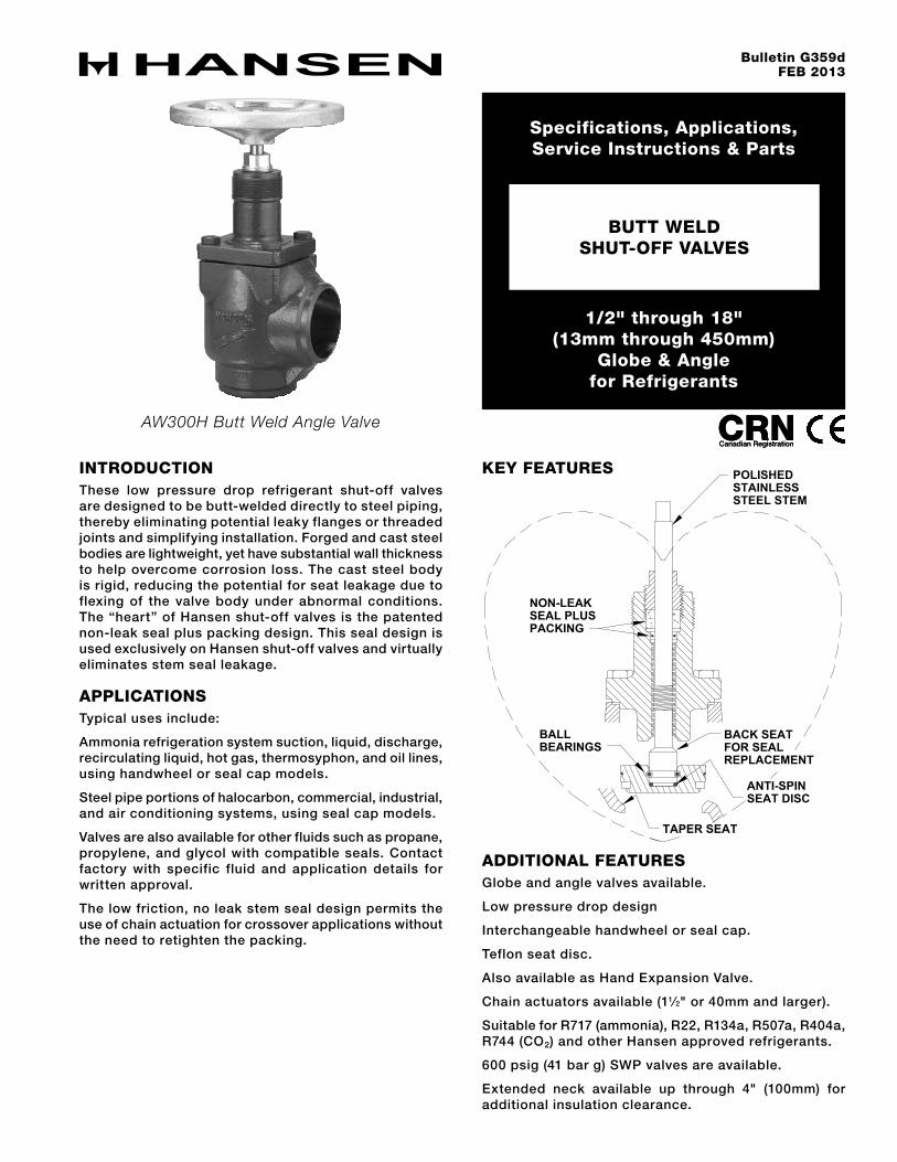
AW300H Butt Weld Angle Valve
INtRoduCtIoNThese low pressure drop refrigerant shut-off valves are designed to be butt-welded directly to steel piping, thereby eliminating potential leaky flanges or threaded joints and simplifying installation. Forged and cast steel bodies are lightweight, yet have substantial wall thickness to help overcome corrosion loss. The cast steel body is rigid, reducing the potential for seat leakage due to flexing of the valve body under abnormal conditions. The “heart” of Hansen shut-off valves is the patented non-leak seal plus packing design. This seal design is used exclusively on Hansen shut-off valves and virtually eliminates stem seal leakage.
APPlICAtIoNSTypical uses include:
Ammonia refrigeration system suction, liquid, discharge, recirculating liquid, hot gas, thermosyphon, and oil lines, using handwheel or seal cap models.
Steel pipe portions of halocarbon, commercial, industrial, and air conditioning systems, using seal cap models.
Valves are also available for other fluids such as propane, propylene, and glycol with compatible seals. Contact factory with specific fluid and application details for written approval.
The low friction, no leak stem seal design permits the use of chain actuation for crossover applications without the need to retighten the packing.
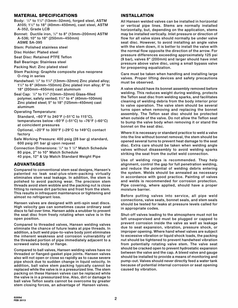
KeY feAtuReS
AddItIoNAl feAtuReSGlobe and angle valves available.
Low pressure drop design
Interchangeable handwheel or seal cap.
Teflon seat disc.
Also available as Hand Expansion Valve.
Chain actuators available (11⁄2" or 40mm and larger).
Suitable for R717 (ammonia), R22, R134a, R507a, R404a, R744 (CO2) and other Hansen approved refrigerants.
600 psig (41 bar g) SWP valves are available.
Extended neck available up through 4" (100mm) for additional insulation clearance.
BALLBEARINGS
TAPER SEAT
BACK SEATFOR SEALREPLACEMENT
NON-LEAKSEAL PLUSPACKING
POLISHEDSTAINLESSSTEEL STEM
ANTI-SPINSEAT DISC
2G359d FEB 2013
MAteRIAl SPeCIfICAtIoNSBody: 1⁄2" to 11⁄4" (13mm–32mm), forged steel, ASTM
A105; 11⁄2" to 18" (40mm–450mm), cast steel, ASTM A-352, Grade LCB
Bonnet: Ductile iron, 1⁄2" to 8" (13mm–200mm) ASTM A-536; 10" to 18" (250mm–450mm) ASME SA-395
Stem: Polished stainless steel Disc Holder: Plated steelSeat Disc: Retained PTFE TeflonBall Bearings: Stainless steelPacking Nut: Zinc plated steelStem Packing: Graphite composite plus neoprene
O-ring in seriesHandwheel: 1⁄2" to 11⁄4" (13mm–32mm) Zinc plated alloy;
11⁄2" to 6" (40mm–150mm) Zinc plated iron alloy; 8" to 18" (200mm–450mm) cast aluminum
Seal Cap: 1⁄2" to 11⁄4" (13mm–32mm) Glass-filled polymer, safety vented; 11⁄2" to 4" (40mm–100mm) Zinc plated steel; 5" to 18" (125mm–450mm) cast aluminum
Operating Temperature: Standard, –60°F to 240°F (–51°C to 115°C),
temperatures below –60°F (–51°C) to –76°F (–60°C) at coincident pressures
Optional, –20°F to 300°F (–29°C to 149°C) contact factory
Safe Working Pressure: 400 psig (28 bar g) standard, 600 psig (41 bar g) upon request
Connection Dimensions: 1⁄2" to 1 1⁄2" Match Schedule 80 pipe, 2" to 10" Match Schedule 40 pipe, 12" & Up Match Standard Weight Pipe
AdvANtAGeSCompared to conventional stem seal designs, Hansen’s patented no leak seal-plus-stem-packing vir tually eliminates stem seal leakage. In addition, the stem is polished to avoid packing wear. The precision stem threads avoid stem wobble and the packing nut is close fitting to remove dirt particles and frost from the stem. This results in infrequent maintenance or tightening and almost no refrigerant loss.
Hansen valves are designed with anti-spin seat discs. High velocity gas can sometimes cause ordinary seat discs to fail over time. Hansen adds a snubber to prevent the seat disc from freely rotating when valve is in the open position.
Compared to threaded valves, Hansen welding valves eliminate the chance of future leaks at pipe threads. In addition, a butt weld pipe-to-valve body joint eliminates the inherent weakness and corrosion vulnerability of the threaded portion of pipe immediately adjacent to a screwed valve body or flange.
Compared to ball valves, Hansen welding valves have no threaded or flanged-gasket pipe joints. Hansen valves also will not open or close so rapidly as to cause severe pipe shock due to sudden change in liquid velocity. In addition, ball valve stem packing typically cannot be replaced while the valve is in a pressurized line. The stem packing on these Hansen valves can be replaced while the valve is in a pressurized line. Also, dirt or damage to ball valve Teflon seats cannot be overcome by greater stem closing forces, an advantage of Hansen valves.
INStAllAtIoNAll Hansen welded valves can be installed in horizontal or vertical pipe lines. Stems are normally installed horizontally, but, depending on the application, stems may be installed vertically. Inlet pressure or direction of flow for all valve sizes should normally be under valve seat disc. However, to avoid installing an angle valve with the stem down, it is better to install the valve with the normal flow opposite the direction of the arrow. For pressure differences exceeding approximately 125 psi (9 bar), valves 8" (200mm) and larger should have inlet pressure above valve disc, using a small bypass valve for preopening equalization.
Care must be taken when handling and installing large valves. Proper lifting devices and safety precautions must be observed.
A valve should have its bonnet assembly removed before welding. This reduces weight during welding, protects the Teflon seat disc from welding sparks, and facilitates cleaning of welding debris from the body interior prior to valve operation. The valve stem should be several turns open when removing and replacing the bonnet assembly. The Teflon seat disc should be protected when outside of the valve. Do not allow the Teflon seat to bump the valve body when removing it or stand the bonnet on the seat disc.
Where it is necessary or standard practice to weld a valve into the line without bonnet removal, the stem should be opened several turns to prevent heat damage to the seat disc. Extra care should be taken when welding angle valves without disassembly to avoid welding sparks striking the seat from the outlet weld connection.
Use of welding rings is recommended. They help alignment, control the gap for full penetration welding, and reduce the potential of welding debris entering the system. Welds should be annealed as necessary in accordance with good practice. Painting of valves and welds is recommended for corrosion protection. Pipe covering, where applied, should have a proper moisture barrier.
Before putting valves into service, all pipe weld connections, valve seats, bonnet seals, and stem seals should be tested for leaks at pressure levels called for in appropriate codes.
Shut-off valves leading to the atmosphere must not be left unsupervised and must be plugged or capped to prevent corrosion inside the valve as well as leakage due to seat expansion, vibration, pressure shock, or improper opening. Where hand wheel valves are subject to excessive vibration or liquid shock loads, the packing nut should be tightened to prevent handwheel vibration from potentially rotating valve stem. The valve seat should be cracked open to prevent hydrostatic expansion between the valve and the cap. A bleed valve and gauge should be installed to provide a means of monitoring and pump-out. Valves should never directly feed a water tank because of potential internal corrosion or seat opening caused by vibration.
3 G359dFEB 2013
INSulAtIoNConventional valve-shaped block insulat ion can occasionally be used for both angle and globe valves. However, fabricated insulation shapes are recommended. If not available locally, Hansen can recommend a source of high quality, economical valve insulation. For exterior valve insulation dimensions refer to Sales Drawing 5002-28.
exteNded NeCK vAlveSHansen bonnets with extended necks, 1/2" thru 4" (13mm–100mm), meet or exceed the recommended low temperature insulation thickness dimensions of the IIAR Piping Handbook. In addition, the stem and packing nut trim are upgraded to 316 stainless steel materials. Stainless steel trim is recommended for environments where severe corrosive conditions exist. (Add an “E” suffix to the model number, for example AWE200C or GWE150H.)
SIZING GuIdeThese flow capacity recommendations are not affected by the length of the pipe line. These are approximate optimum sizes based on power costs versus the investment costs of piping and its total installed cost. Piping sized to this capacity will have a 1°F (0.6°C) pressure drop for the following equivalent lengths:
suction lines . . . . . . . 700 diameters
discharge lines . . . . . 1400 diameters
liquid lines . . . . . . . . . 2400 diameters
Example: 275 feet (84m) of 3" (80mm) pipe and equivalent fittings amount to 1100 diameters, pressure drop for a suction line handling 81.5 tons (287 kW) at 20°F (–7°C) is 1100/700 times 1°F (0.6°C) drop, equals 1.6°F (1°C) or 1.8 psi (0.12 bar).
Example: Hansen valves have about 145 diameters of equivalent flow resistance, or 145/700 = 0.2°F (0.12°C) of equivalent pressure drop at the suction line capacities shown for a valve in a suction line.
The rationale for the vapor line sizing was developed by William V. Richards in two papers: “Refrigerant Vapor Line Sizing Not Dependent of Length,” 16th International Congress of Refrigeration, IIR, Paris, 1983; and “Practical Pipe Sizing for Refrigerant Vapor Lines,” Sixth Annual Meetings, IIAR, San Francisco, 1984.
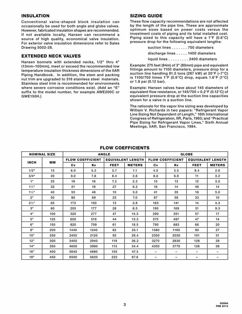
floW CoeffICIeNtSNoMINAl SIZe ANGle GloBe
INCh MMfloW CoeffICIeNt equIvAleNt leNGth floW CoeffICIeNt equIvAleNt leNGth
Cv Kv feet MeteRS Cv Kv feet MeteRS
1/2" 13 6.0 5.2 3.7 1.1 4.0 3.5 8.4 2.6
3/4" 20 9.0 7.8 8.4 2.6 8.0 6.9 11 3.2
1" 25 19 16 7.2 2.2 15 13 12 3.5
11⁄4" 32 21 18 27 8.2 16 14 46 14
11⁄2" 40 53 46 10 3.0 41 35 16 5.0
2" 50 80 69 23 7.0 67 58 33 10
21⁄2" 65 173 150 13 3.8 163 141 14 4.3
3" 80 205 177 28 8.5 195 169 31 9.3
4" 100 320 277 47 14.3 290 251 57 17
5" 125 600 519 44 13.3 575 497 47 14
6" 150 820 709 61 18.5 790 683 66 20
8" 200 1440 1240 82 25.1 1380 1190 90 27
10" 250 2450 2120 93 28.4 2350 2030 101 31
12" 300 3400 2940 119 36.2 3270 2830 128 39
14" 350 4600 3980 113 34.4 4350 3770 126 38
16" 400 5640 4880 155 47.3 – – – –
18" 450 6500 5620 222 67.6 – – – –
4G359d FEB 2013
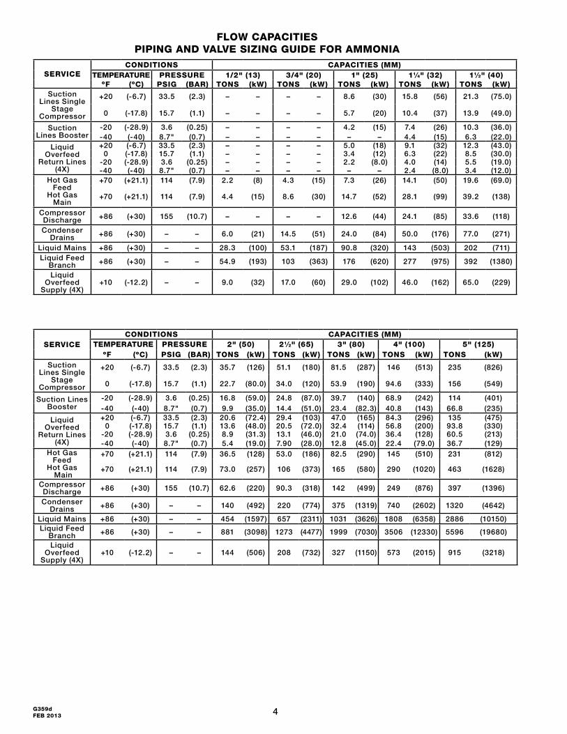
SeRvICeCoNdItIoNS CAPACItIeS (MM)
teMPeRAtuRe PReSSuRe 2" (50) 21⁄2" (65) 3" (80) 4" (100) 5" (125)ºf (ºC) PSIG (BAR) toNS (kW) toNS (kW) toNS (kW) toNS (kW) toNS (kW)
Suction Lines Single
Stage Compressor
+20 (-6.7) 33.5 (2.3) 35.7 (126) 51.1 (180) 81.5 (287) 146 (513) 235 (826)
0 (-17.8) 15.7 (1.1) 22.7 (80.0) 34.0 (120) 53.9 (190) 94.6 (333) 156 (549)
Suction Lines Booster
-20 (-28.9) 3.6 (0.25) 16.8 (59.0) 24.8 (87.0) 39.7 (140) 68.9 (242) 114 (401)-40 (-40) 8.7" (0.7) 9.9 (35.0) 14.4 (51.0) 23.4 (82.3) 40.8 (143) 66.8 (235)
Liquid Overfeed
Return Lines (4X)
+20 (-6.7) 33.5 (2.3) 20.6 (72.4) 29.4 (103) 47.0 (165) 84.3 (296) 135 (475)0 (-17.8) 15.7 (1.1) 13.6 (48.0) 20.5 (72.0) 32.4 (114) 56.8 (200) 93.8 (330)
-20 (-28.9) 3.6 (0.25) 8.9 (31.3) 13.1 (46.0) 21.0 (74.0) 36.4 (128) 60.5 (213)-40 (-40) 8.7" (0.7) 5.4 (19.0) 7.90 (28.0) 12.8 (45.0) 22.4 (79.0) 36.7 (129)
Hot Gas Feed
Hot Gas Main
+70 (+21.1) 114 (7.9) 36.5 (128) 53.0 (186) 82.5 (290) 145 (510) 231 (812)
+70 (+21.1) 114 (7.9) 73.0 (257) 106 (373) 165 (580) 290 (1020) 463 (1628)
Compressor Discharge +86 (+30) 155 (10.7) 62.6 (220) 90.3 (318) 142 (499) 249 (876) 397 (1396)
Condenser Drains +86 (+30) – – 140 (492) 220 (774) 375 (1319) 740 (2602) 1320 (4642)
Liquid Mains +86 (+30) – – 454 (1597) 657 (2311) 1031 (3626) 1808 (6358) 2886 (10150)Liquid Feed
Branch +86 (+30) – – 881 (3098) 1273 (4477) 1999 (7030) 3506 (12330) 5596 (19680)
Liquid Overfeed
Supply (4X)+10 (-12.2) – – 144 (506) 208 (732) 327 (1150) 573 (2015) 915 (3218)
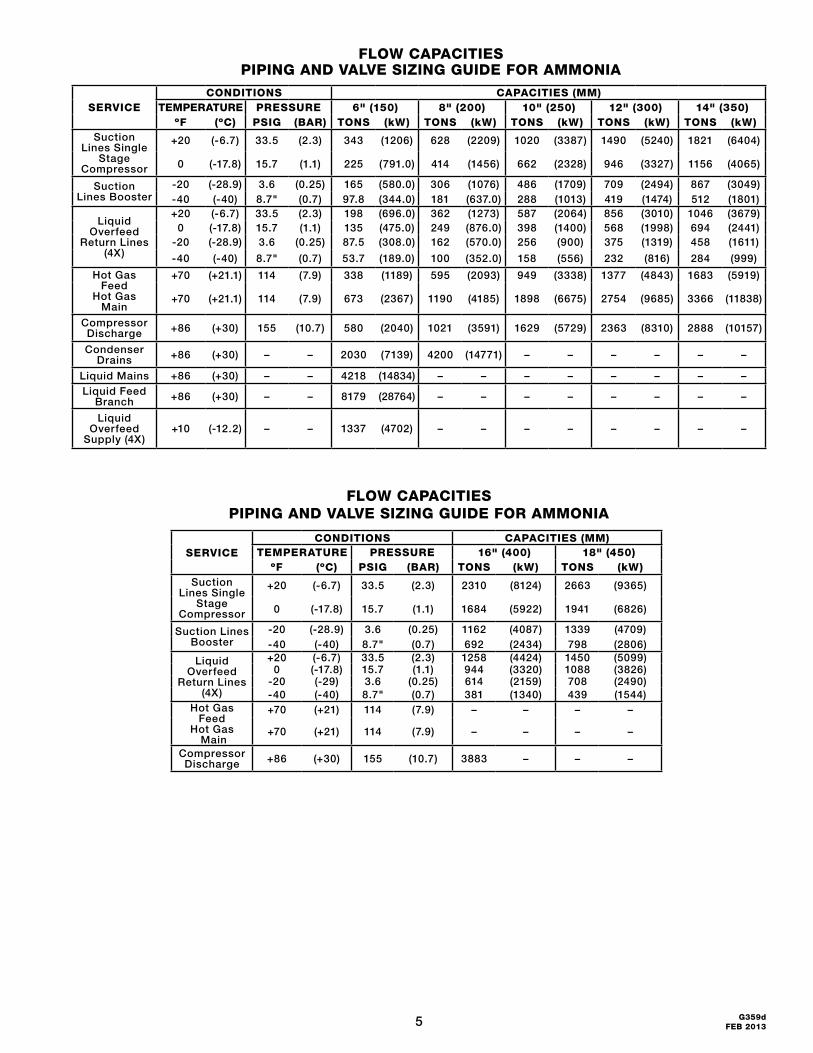
floW CAPACItIeS PIPING ANd vAlve SIZING GuIde foR AMMoNIA
SeRvICeCoNdItIoNS CAPACItIeS (MM)
teMPeRAtuRe PReSSuRe 1/2" (13) 3/4" (20) 1" (25) 11⁄4" (32) 11⁄2" (40)ºf (ºC) PSIG (BAR) toNS (kW) toNS (kW) toNS (kW) toNS (kW) toNS (kW)
Suction Lines Single
Stage Compressor
+20 (-6.7) 33.5 (2.3) – – – – 8.6 (30) 15.8 (56) 21.3 (75.0)
0 (-17.8) 15.7 (1.1) – – – – 5.7 (20) 10.4 (37) 13.9 (49.0)
Suction Lines Booster
-20 (-28.9) 3.6 (0.25) – – – – 4.2 (15) 7.4 (26) 10.3 (36.0)-40 (-40) 8.7" (0.7) – – – – – – 4.4 (15) 6.3 (22.0)
Liquid Overfeed
Return Lines (4X)
+20 (-6.7) 33.5 (2.3) – – – – 5.0 (18) 9.1 (32) 12.3 (43.0)0 (-17.8) 15.7 (1.1) – – – – 3.4 (12) 6.3 (22) 8.5 (30.0)
-20 (-28.9) 3.6 (0.25) – – – – 2.2 (8.0) 4.0 (14) 5.5 (19.0)-40 (-40) 8.7" (0.7) – – – – – – 2.4 (8.0) 3.4 (12.0)
Hot Gas Feed
Hot Gas Main
+70 (+21.1) 114 (7.9) 2.2 (8) 4.3 (15) 7.3 (26) 14.1 (50) 19.6 (69.0)
+70 (+21.1) 114 (7.9) 4.4 (15) 8.6 (30) 14.7 (52) 28.1 (99) 39.2 (138)
Compressor Discharge +86 (+30) 155 (10.7) – – – – 12.6 (44) 24.1 (85) 33.6 (118)
Condenser Drains +86 (+30) – – 6.0 (21) 14.5 (51) 24.0 (84) 50.0 (176) 77.0 (271)
Liquid Mains +86 (+30) – – 28.3 (100) 53.1 (187) 90.8 (320) 143 (503) 202 (711)Liquid Feed
Branch +86 (+30) – – 54.9 (193) 103 (363) 176 (620) 277 (975) 392 (1380)
Liquid Overfeed
Supply (4X)+10 (-12.2) – – 9.0 (32) 17.0 (60) 29.0 (102) 46.0 (162) 65.0 (229)
5 G359dFEB 2013
floW CAPACItIeS PIPING ANd vAlve SIZING GuIde foR AMMoNIA
SeRvICeCoNdItIoNS CAPACItIeS (MM)
teMPeRAtuRe PReSSuRe 6" (150) 8" (200) 10" (250) 12" (300) 14" (350)ºf (ºC) PSIG (BAR) toNS (kW) toNS (kW) toNS (kW) toNS (kW) toNS (kW)
Suction Lines Single
Stage Compressor
+20 (-6.7) 33.5 (2.3) 343 (1206) 628 (2209) 1020 (3387) 1490 (5240) 1821 (6404)
0 (-17.8) 15.7 (1.1) 225 (791.0) 414 (1456) 662 (2328) 946 (3327) 1156 (4065)
Suction Lines Booster
-20 (-28.9) 3.6 (0.25) 165 (580.0) 306 (1076) 486 (1709) 709 (2494) 867 (3049)-40 (-40) 8.7" (0.7) 97.8 (344.0) 181 (637.0) 288 (1013) 419 (1474) 512 (1801)
Liquid Overfeed
Return Lines (4X)
+20 (-6.7) 33.5 (2.3) 198 (696.0) 362 (1273) 587 (2064) 856 (3010) 1046 (3679)0 (-17.8) 15.7 (1.1) 135 (475.0) 249 (876.0) 398 (1400) 568 (1998) 694 (2441)
-20 (-28.9) 3.6 (0.25) 87.5 (308.0) 162 (570.0) 256 (900) 375 (1319) 458 (1611)
-40 (-40) 8.7" (0.7) 53.7 (189.0) 100 (352.0) 158 (556) 232 (816) 284 (999)
Hot Gas Feed
Hot Gas Main
+70 (+21.1) 114 (7.9) 338 (1189) 595 (2093) 949 (3338) 1377 (4843) 1683 (5919)
+70 (+21.1) 114 (7.9) 673 (2367) 1190 (4185) 1898 (6675) 2754 (9685) 3366 (11838)
Compressor Discharge +86 (+30) 155 (10.7) 580 (2040) 1021 (3591) 1629 (5729) 2363 (8310) 2888 (10157)
Condenser Drains +86 (+30) – – 2030 (7139) 4200 (14771) – – – – – –
Liquid Mains +86 (+30) – – 4218 (14834) – – – – – – – –Liquid Feed
Branch +86 (+30) – – 8179 (28764) – – – – – – – –
Liquid Overfeed
Supply (4X)+10 (-12.2) – – 1337 (4702) – – – – – – – –
floW CAPACItIeS PIPING ANd vAlve SIZING GuIde foR AMMoNIA
SeRvICeCoNdItIoNS CAPACItIeS (MM)
teMPeRAtuRe PReSSuRe 16" (400) 18" (450)ºf (ºC) PSIG (BAR) toNS (kW) toNS (kW)
Suction Lines Single
Stage Compressor
+20 (-6.7) 33.5 (2.3) 2310 (8124) 2663 (9365)
0 (-17.8) 15.7 (1.1) 1684 (5922) 1941 (6826)
Suction Lines Booster
-20 (-28.9) 3.6 (0.25) 1162 (4087) 1339 (4709)-40 (-40) 8.7" (0.7) 692 (2434) 798 (2806)
Liquid Overfeed
Return Lines (4X)
+20 (-6.7) 33.5 (2.3) 1258 (4424) 1450 (5099)0 (-17.8) 15.7 (1.1) 944 (3320) 1088 (3826)
-20 (-29) 3.6 (0.25) 614 (2159) 708 (2490)-40 (-40) 8.7" (0.7) 381 (1340) 439 (1544)
Hot Gas Feed
Hot Gas Main
+70 (+21) 114 (7.9) – – – –
+70 (+21) 114 (7.9) – – – –
Compressor Discharge +86 (+30) 155 (10.7) 3883 – – –
6G359d FEB 2013
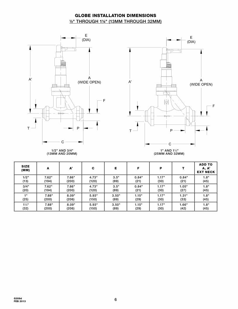
GloBe INStAllAtIoN dIMeNSIoNS½" THROUGH 1¼" (13MM THROUGH 32MM)
SIZe(MM)
A A' C e f P tAdd to
A, A' ext NeCK
1/2" (13)
7.62"(194)
7.86"(200)
4.73"(120)
3.5"(89)
0.84"(21)
1.17"(30)
0.84"(21)
1.8"(45)
3/4" (20)
7.62"(194)
7.86"(200)
4.73"(120)
3.5"(89)
0.84"(21)
1.17"(30)
1.05"(27)
1.8"(45)
1" (25)
7.88"(200)
8.09"(206)
5.93"(150)
3.50"(89)
1.15"(29)
1.17"(30)
1.31"(33)
1.8"(45)
11⁄4" (32)
7.88"(200)
8.09"(206)
5.93"(150)
3.50"(89)
1.15"(29)
1.17"(30)
1.66"(42)
1.8"(45)
1/2" AND 3/4"(13MM AND 20MM)
1" AND 11⁄4"(25MM AND 32MM)
A(WIDE OPEN)
F
C
P
A'
E(DIA)
T
A(WIDE OPEN)
F
E(DIA)
A'
P
C
T
7 G359dFEB 2013
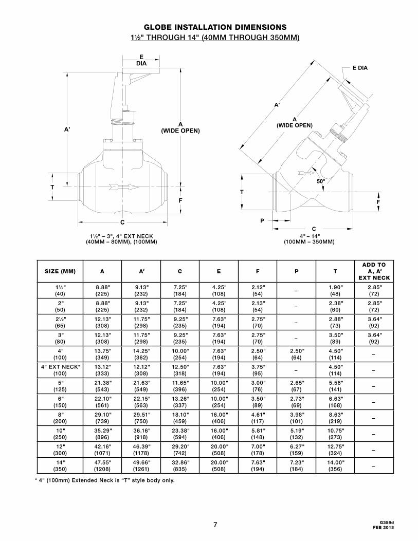
GloBe INStAllAtIoN dIMeNSIoNS1½" THROUGH 14" (40MM THROUGH 350MM)
SIZe (MM) A A' C e f P tAdd to
A, A' ext NeCK
11⁄2"(40)
8.88"(225)
9.13"(232)
7.25"(184)
4.25"(108)
2.12"(54)
−1.90"(48)
2.85"(72)
2"(50)
8.88"(225)
9.13"(232)
7.25"(184)
4.25"(108)
2.13"(54)
−2.38"(60)
2.85"(72)
21⁄2"(65)
12.13"(308)
11.75"(298)
9.25"(235)
7.63"(194)
2.75"(70)
−2.88"(73)
3.64"(92)
3"(80)
12.13"(308)
11.75"(298)
9.25"(235)
7.63"(194)
2.75"(70)
−3.50"(89)
3.64"(92)
4"(100)
13.75"(349)
14.25"(362)
10.00"(254)
7.63"(194)
2.50"(64)
2.50"(64)
4.50"(114)
−
4" EXT NECK*(100)
13.12"(333)
12.12"(308)
12.50"(318)
7.63"(194)
3.75"(95)
−4.50"(114)
−
5"(125)
21.38"(543)
21.63"(549)
11.65"(396)
10.00"(254)
3.00"(76)
2.65"(67)
5.56"(141)
−
6"(150)
22.10"(561)
22.15"(563)
13.26"(337)
10.00"(254)
3.50"(89)
2.73"(69)
6.63"(168)
−
8"(200)
29.10"(739)
29.51"(750)
18.10"(459)
16.00"(406)
4.61"(117)
3.98"(101)
8.63"(219)
−
10"(250)
35.29"(896)
36.16" (918)
23.38" (594)
16.00" (406)
5.81"(148)
5.19"(132)
10.75"(273)
−
12"(300)
42.16" (1071)
46.39"(1178)
29.20"(742)
20.00"(508)
7.00"(178)
6.27"(159)
12.75"(324)
−
14"(350)
47.55"(1208)
49.66"(1261)
32.86"(835)
20.00"(508)
7.63"(194)
7.23"(184)
14.00"(356)
−
* 4" (100mm) Extended Neck is “T” style body only.
P
A
C
A'
T
50°
F
E DIA
(WIDE OPEN)
11⁄2" – 3", 4" EXT NECK(40MM – 80MM), (100MM)
4" – 14"(100MM – 350MM)
C
T
A'
F
(WIDE OPEN)
DIAE
A
8G359d FEB 2013
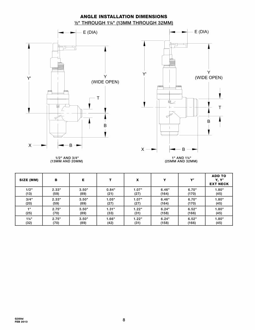
ANGle INStAllAtIoN dIMeNSIoNS½" THROUGH 1¼" (13MM THROUGH 32MM)
SIZe (MM) B e t x Y Y'Add to
Y, Y' ext NeCK
1/2"(13)
2.33"(59)
3.50"(89)
0.84"(21)
1.07"(27)
6.46"(164)
6.70"(170)
1.80"(45)
3/4"(20)
2.33"(59)
3.50"(89)
1.05"(27)
1.07"(27)
6.46"(164)
6.70"(170)
1.80"(45)
1"(25)
2.75"(70)
3.50"(89)
1.31"(33)
1.22"(31)
6.24"(158)
6.52"(166)
1.80"(45)
1¼"(32)
2.75"(70)
3.50"(89)
1.66"(42)
1.22"(31)
6.24"(158)
6.52"(166)
1.80"(45)
1/2" AND 3/4"(13MM AND 20MM)
1" AND 1¼"(25MM AND 32MM)
E (DIA)
Y(WIDE OPEN)
B
B
Y'
X
T
B
B
Y(WIDE OPEN)
Y'
E (DIA)
X
T
9 G359dFEB 2013
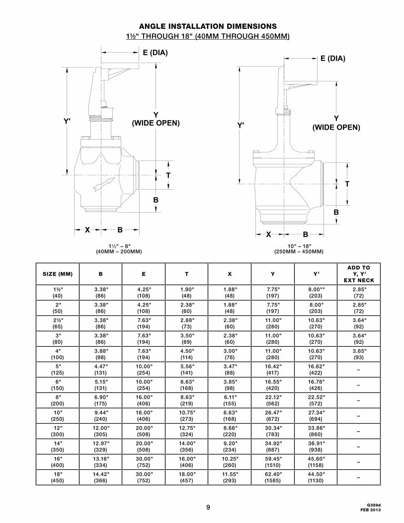
ANGle INStAllAtIoN dIMeNSIoNS1½" THROUGH 18" (40MM THROUGH 450MM)
SIZe (MM) B e t x Y Y'Add to
Y, Y' ext NeCK
1½"(40)
3.38"(86)
4.25"(108)
1.90"(48)
1.88"(48)
7.75"(197)
8.00""(203)
2.85"(72)
2"(50)
3.38"(86)
4.25"(108)
2.38"(60)
1.88"(48)
7.75"(197)
8.00"(203)
2.85"(72)
2½"(65)
3.38"(86)
7.63"(194)
2.88"(73)
2.38"(60)
11.00"(280)
10.63"(270)
3.64"(92)
3"(80)
3.38"(86)
7.63"(194)
3.50"(89)
2.38"(60)
11.00"(280)
10.63"(270)
3.64"(92)
4"(100)
3.88"(98)
7.63"(194)
4.50"(114)
3.00"(76)
11.00"(280)
10.63"(270)
3.65"(93)
5"(125)
4.47"(131)
10.00"(254)
5.56"(141)
3.47"(88)
16.42"(417)
16.62"(422)
–
6"(150)
5.15"(131)
10.00"(254)
6.63"(168)
3.85"(98)
16.55"(420)
16.78"(426)
–
8"(200)
6.90"(175)
16.00"(406)
8.63"(219)
6.11"(155)
22.12"(562)
22.52"(572)
–
10"(250)
9.44"(240)
16.00"(406)
10.75"(273)
6.63"(168)
26.47"(672)
27.34"(694)
–
12"(300)
12.00"(305)
20.00"(508)
12.75"(324)
8.66"(220)
30.34"(783)
33.86"(860)
–
14"(350)
12.97"(329)
20.00"(508)
14.00"(356)
9.20"(234)
34.92"(887)
36.91"(938)
–
16"(400)
13.16"(334)
30.00"(752)
16.00"(406)
10.25"(260)
59.45"(1510)
45.60"(1158)
–
18"(450)
14.42"(366)
30.00"(752)
18.00"(457)
11.55"(293)
62.40"(1585)
44.50"(1130)
–
X
T
(WIDE OPEN)Y'
B
B
Y
E (DIA)
X B
B
T
Y(WIDE OPEN)Y'
E (DIA)
11⁄2" – 8"(40MM – 200MM)
10" – 18"(250MM – 450MM)
10G359d FEB 2013
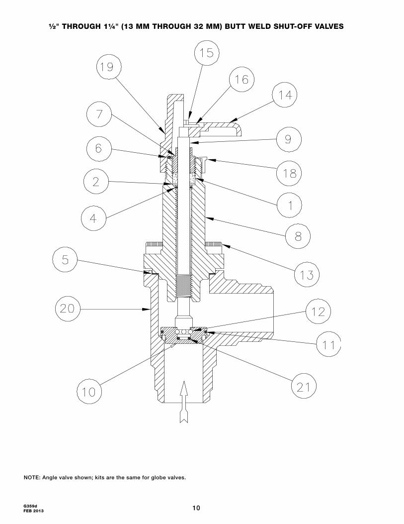
½" thRouGh 1¼" (13 MM thRouGh 32 MM) Butt Weld Shut-off vAlveS
NOTE: Angle valve shown; kits are the same for globe valves.
11 G359dFEB 2013
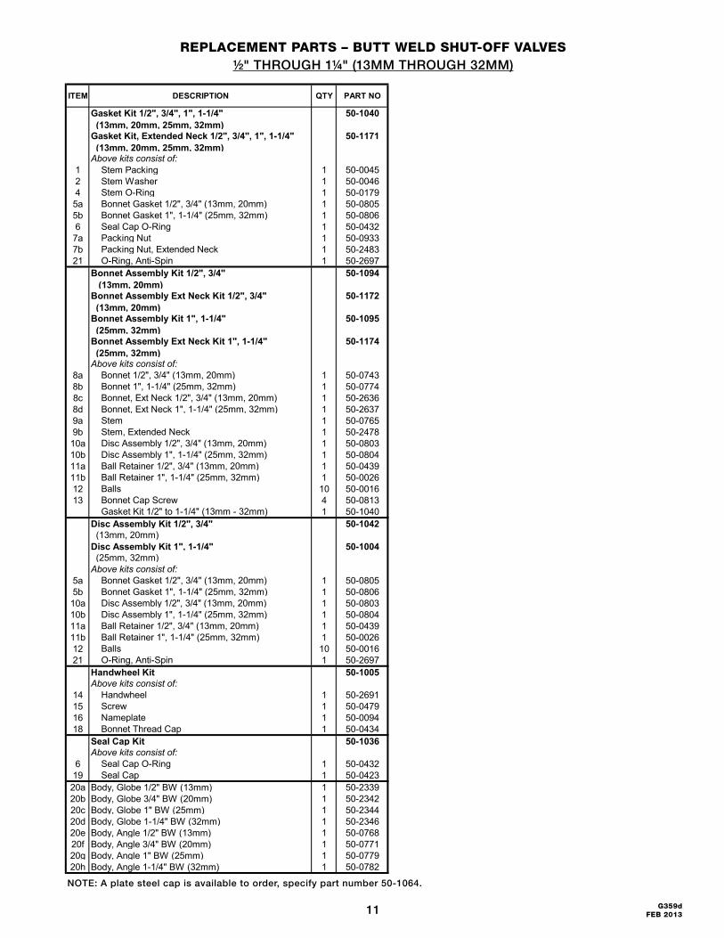
RePlACeMeNt PARtS – Butt Weld Shut-off vAlveS½" THROUGH 1¼" (13MM THROUGH 32MM)
ITEM DESCRIPTION QTY PART NO
Gasket Kit 1/2", 3/4", 1", 1-1/4" (13mm, 20mm, 25mm, 32mm)
50-1040
Gasket Kit, Extended Neck 1/2", 3/4", 1", 1-1/4" (13mm, 20mm, 25mm, 32mm)
50-1171
Above kits consist of:1 Stem Packing 1 50-00452 Stem Washer 1 50-00464 Stem O-Ring 1 50-01795a Bonnet Gasket 1/2", 3/4" (13mm, 20mm) 1 50-08055b Bonnet Gasket 1", 1-1/4" (25mm, 32mm) 1 50-08066 Seal Cap O-Ring 1 50-04327a Packing Nut 1 50-09337b Packing Nut, Extended Neck 1 50-248321 O-Ring, Anti-Spin 1 50-2697
Bonnet Assembly Kit 1/2", 3/4" (13mm, 20mm)
50-1094
Bonnet Assembly Ext Neck Kit 1/2", 3/4" (13mm, 20mm)
50-1172
Bonnet Assembly Kit 1", 1-1/4" (25mm, 32mm)
50-1095
Bonnet Assembly Ext Neck Kit 1", 1-1/4" (25mm, 32mm)
50-1174
Above kits consist of:8a Bonnet 1/2", 3/4" (13mm, 20mm) 1 50-07438b Bonnet 1", 1-1/4" (25mm, 32mm) 1 50-07748c Bonnet, Ext Neck 1/2", 3/4" (13mm, 20mm) 1 50-26368d Bonnet, Ext Neck 1", 1-1/4" (25mm, 32mm) 1 50-26379a Stem 1 50-07659b Stem, Extended Neck 1 50-247810a Disc Assembly 1/2", 3/4" (13mm, 20mm) 1 50-080310b Disc Assembly 1", 1-1/4" (25mm, 32mm) 1 50-080411a Ball Retainer 1/2", 3/4" (13mm, 20mm) 1 50-043911b Ball Retainer 1", 1-1/4" (25mm, 32mm) 1 50-002612 Balls 10 50-001613 Bonnet Cap Screw 4 50-0813
Gasket Kit 1/2" to 1-1/4" (13mm - 32mm) 1 50-1040Disc Assembly Kit 1/2", 3/4" 50-1042 (13mm, 20mm)Disc Assembly Kit 1", 1-1/4" 50-1004 (25mm, 32mm)Above kits consist of:
5a Bonnet Gasket 1/2", 3/4" (13mm, 20mm) 1 50-08055b Bonnet Gasket 1", 1-1/4" (25mm, 32mm) 1 50-080610a Disc Assembly 1/2", 3/4" (13mm, 20mm) 1 50-080310b Disc Assembly 1", 1-1/4" (25mm, 32mm) 1 50-080411a Ball Retainer 1/2", 3/4" (13mm, 20mm) 1 50-043911b Ball Retainer 1", 1-1/4" (25mm, 32mm) 1 50-002612 Balls 10 50-001621 O-Ring, Anti-Spin 1 50-2697
Handwheel Kit 50-1005Above kits consist of:
14 Handwheel 1 50-269115 Screw 1 50-047916 Nameplate 1 50-009418 Bonnet Thread Cap 1 50-0434
Seal Cap Kit 50-1036Above kits consist of:
6 Seal Cap O-Ring 1 50-043219 Seal Cap 1 50-042320a Body, Globe 1/2" BW (13mm) 1 50-233920b Body, Globe 3/4" BW (20mm) 1 50-234220c Body, Globe 1" BW (25mm) 1 50-234420d Body, Globe 1-1/4" BW (32mm) 1 50-234620e Body, Angle 1/2" BW (13mm) 1 50-076820f Body, Angle 3/4" BW (20mm) 1 50-077120g Body, Angle 1" BW (25mm) 1 50-077920h Body, Angle 1-1/4" BW (32mm) 1 50-0782
NOTE: A plate steel cap is available to order, specify part number 50-1064.
12G359d FEB 2013
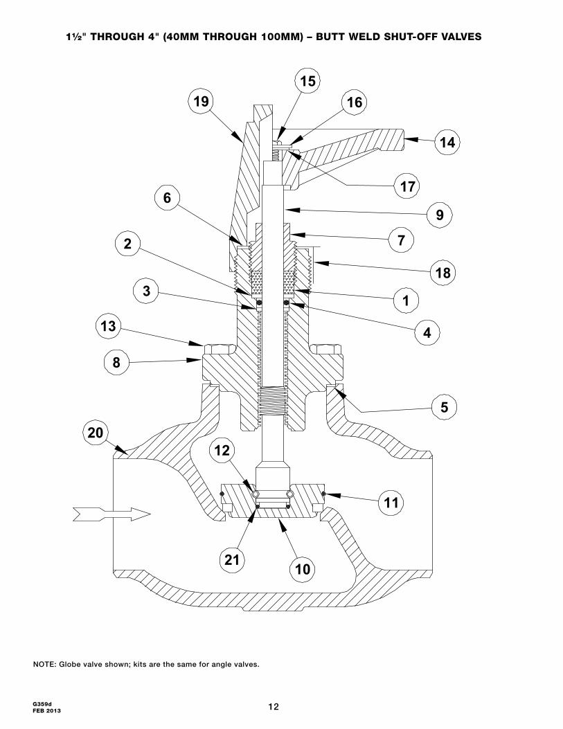
1½" thRouGh 4" (40MM thRouGh 100MM) – Butt Weld Shut-off vAlveS
NOTE: Globe valve shown; kits are the same for angle valves.
20
1
2
4
5
6
7
8
9
21
11
12
13
14
1516
17
18
19
3
10
13 G359dFEB 2013
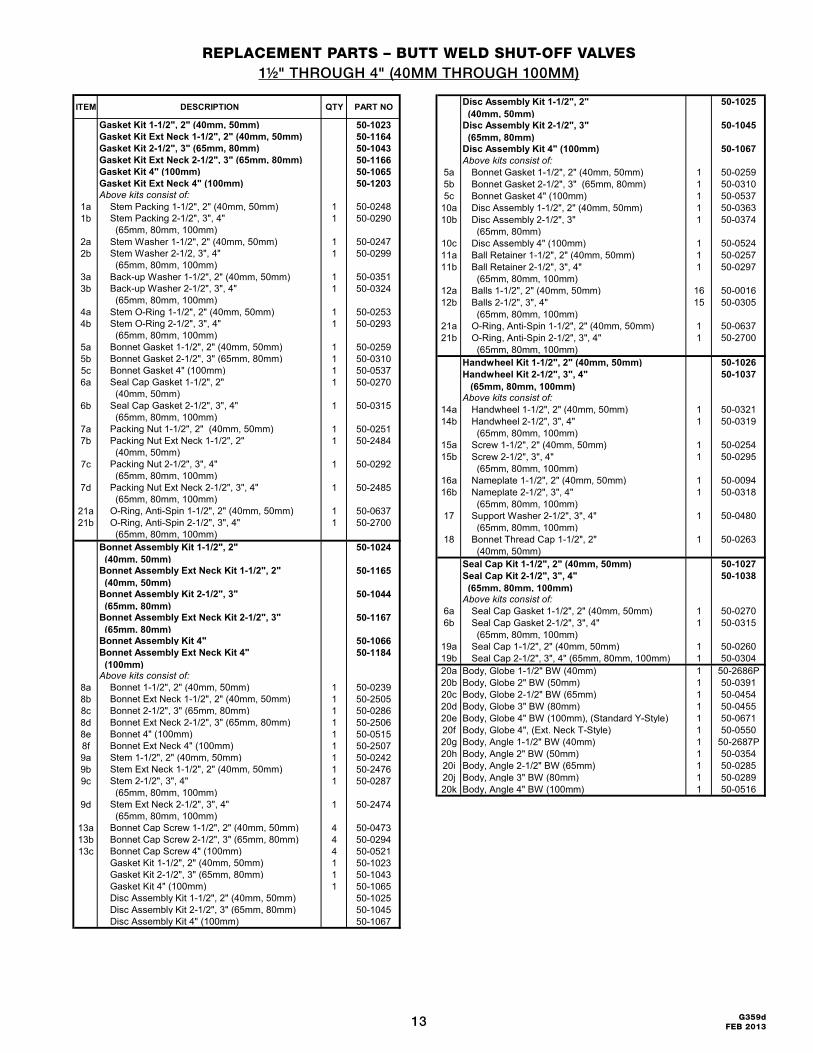
RePlACeMeNt PARtS – Butt Weld Shut-off vAlveS1½" THROUGH 4" (40MM THROUGH 100MM)
ITEM DESCRIPTION QTY PART NO
Gasket Kit 1-1/2", 2" (40mm, 50mm) 50-1023Gasket Kit Ext Neck 1-1/2", 2" (40mm, 50mm) 50-1164Gasket Kit 2-1/2", 3" (65mm, 80mm) 50-1043Gasket Kit Ext Neck 2-1/2", 3" (65mm, 80mm) 50-1166Gasket Kit 4" (100mm) 50-1065Gasket Kit Ext Neck 4" (100mm) 50-1203Above kits consist of:
1a Stem Packing 1-1/2", 2" (40mm, 50mm) 1 50-02481b Stem Packing 2-1/2", 3", 4"
(65mm, 80mm, 100mm)1 50-0290
2a Stem Washer 1-1/2", 2" (40mm, 50mm) 1 50-02472b Stem Washer 2-1/2, 3", 4"
(65mm, 80mm, 100mm)1 50-0299
3a Back-up Washer 1-1/2", 2" (40mm, 50mm) 1 50-03513b Back-up Washer 2-1/2", 3", 4"
(65mm, 80mm, 100mm)1 50-0324
4a Stem O-Ring 1-1/2", 2" (40mm, 50mm) 1 50-02534b Stem O-Ring 2-1/2", 3", 4"
(65mm, 80mm, 100mm)1 50-0293
5a Bonnet Gasket 1-1/2", 2" (40mm, 50mm) 1 50-02595b Bonnet Gasket 2-1/2", 3" (65mm, 80mm) 1 50-03105c Bonnet Gasket 4" (100mm) 1 50-05376a Seal Cap Gasket 1-1/2", 2"
(40mm, 50mm)1 50-0270
6b Seal Cap Gasket 2-1/2", 3", 4" (65mm, 80mm, 100mm)
1 50-0315
7a Packing Nut 1-1/2", 2" (40mm, 50mm) 1 50-02517b Packing Nut Ext Neck 1-1/2", 2"
(40mm, 50mm)1 50-2484
7c Packing Nut 2-1/2", 3", 4" (65mm, 80mm, 100mm)
1 50-0292
7d Packing Nut Ext Neck 2-1/2", 3", 4" (65mm, 80mm, 100mm)
1 50-2485
21a O-Ring, Anti-Spin 1-1/2", 2" (40mm, 50mm) 1 50-063721b O-Ring, Anti-Spin 2-1/2", 3", 4"
(65mm, 80mm, 100mm)1 50-2700
Bonnet Assembly Kit 1-1/2", 2" (40mm, 50mm)
50-1024
Bonnet Assembly Ext Neck Kit 1-1/2", 2" (40mm, 50mm)
50-1165
Bonnet Assembly Kit 2-1/2", 3" (65mm, 80mm)
50-1044
Bonnet Assembly Ext Neck Kit 2-1/2", 3" (65mm, 80mm)
50-1167
Bonnet Assembly Kit 4" 50-1066Bonnet Assembly Ext Neck Kit 4" (100mm)
50-1184
Above kits consist of:8a Bonnet 1-1/2", 2" (40mm, 50mm) 1 50-02398b Bonnet Ext Neck 1-1/2", 2" (40mm, 50mm) 1 50-25058c Bonnet 2-1/2", 3" (65mm, 80mm) 1 50-02868d Bonnet Ext Neck 2-1/2", 3" (65mm, 80mm) 1 50-25068e Bonnet 4" (100mm) 1 50-05158f Bonnet Ext Neck 4" (100mm) 1 50-25079a Stem 1-1/2", 2" (40mm, 50mm) 1 50-02429b Stem Ext Neck 1-1/2", 2" (40mm, 50mm) 1 50-24769c Stem 2-1/2", 3", 4"
(65mm, 80mm, 100mm)1 50-0287
9d Stem Ext Neck 2-1/2", 3", 4" (65mm, 80mm, 100mm)
1 50-2474
13a Bonnet Cap Screw 1-1/2", 2" (40mm, 50mm) 4 50-047313b Bonnet Cap Screw 2-1/2", 3" (65mm, 80mm) 4 50-029413c Bonnet Cap Screw 4" (100mm) 4 50-0521
Gasket Kit 1-1/2", 2" (40mm, 50mm) 1 50-1023Gasket Kit 2-1/2", 3" (65mm, 80mm) 1 50-1043Gasket Kit 4" (100mm) 1 50-1065Disc Assembly Kit 1-1/2", 2" (40mm, 50mm) 50-1025Disc Assembly Kit 2-1/2", 3" (65mm, 80mm) 50-1045Disc Assembly Kit 4" (100mm) 50-1067
Disc Assembly Kit 1-1/2", 2" (40mm, 50mm)
50-1025
Disc Assembly Kit 2-1/2", 3" (65mm, 80mm)
50-1045
Disc Assembly Kit 4" (100mm) 50-1067Above kits consist of:
5a Bonnet Gasket 1-1/2", 2" (40mm, 50mm) 1 50-02595b Bonnet Gasket 2-1/2", 3" (65mm, 80mm) 1 50-03105c Bonnet Gasket 4" (100mm) 1 50-0537
10a Disc Assembly 1-1/2", 2" (40mm, 50mm) 1 50-036310b Disc Assembly 2-1/2", 3"
(65mm, 80mm)1 50-0374
10c Disc Assembly 4" (100mm) 1 50-052411a Ball Retainer 1-1/2", 2" (40mm, 50mm) 1 50-025711b Ball Retainer 2-1/2", 3", 4"
(65mm, 80mm, 100mm)1 50-0297
12a Balls 1-1/2", 2" (40mm, 50mm) 16 50-001612b Balls 2-1/2", 3", 4"
(65mm, 80mm, 100mm)15 50-0305
21a O-Ring, Anti-Spin 1-1/2", 2" (40mm, 50mm) 1 50-063721b O-Ring, Anti-Spin 2-1/2", 3", 4"
(65mm, 80mm, 100mm)1 50-2700
Handwheel Kit 1-1/2", 2" (40mm, 50mm) 50-1026Handwheel Kit 2-1/2", 3", 4" (65mm, 80mm, 100mm)
50-1037
Above kits consist of:14a Handwheel 1-1/2", 2" (40mm, 50mm) 1 50-032114b Handwheel 2-1/2", 3", 4"
(65mm, 80mm, 100mm)1 50-0319
15a Screw 1-1/2", 2" (40mm, 50mm) 1 50-025415b Screw 2-1/2", 3", 4"
(65mm, 80mm, 100mm)1 50-0295
16a Nameplate 1-1/2", 2" (40mm, 50mm) 1 50-009416b Nameplate 2-1/2", 3", 4"
(65mm, 80mm, 100mm)1 50-0318
17 Support Washer 2-1/2", 3", 4" (65mm, 80mm, 100mm)
1 50-0480
18 Bonnet Thread Cap 1-1/2", 2" (40mm, 50mm)
1 50-0263
Seal Cap Kit 1-1/2", 2" (40mm, 50mm) 50-1027Seal Cap Kit 2-1/2", 3", 4" (65mm, 80mm, 100mm)
50-1038
Above kits consist of:6a Seal Cap Gasket 1-1/2", 2" (40mm, 50mm) 1 50-02706b Seal Cap Gasket 2-1/2", 3", 4"
(65mm, 80mm, 100mm)1 50-0315
19a Seal Cap 1-1/2", 2" (40mm, 50mm) 1 50-026019b Seal Cap 2-1/2", 3", 4" (65mm, 80mm, 100mm) 1 50-030420a Body, Globe 1-1/2" BW (40mm) 1 50-2686P20b Body, Globe 2" BW (50mm) 1 50-039120c Body, Globe 2-1/2" BW (65mm) 1 50-045420d Body, Globe 3" BW (80mm) 1 50-045520e Body, Globe 4" BW (100mm), (Standard Y-Style) 1 50-067120f Body, Globe 4", (Ext. Neck T-Style) 1 50-055020g Body, Angle 1-1/2" BW (40mm) 1 50-2687P20h Body, Angle 2" BW (50mm) 1 50-035420i Body, Angle 2-1/2" BW (65mm) 1 50-028520j Body, Angle 3" BW (80mm) 1 50-028920k Body, Angle 4" BW (100mm) 1 50-0516
14G359d FEB 2013
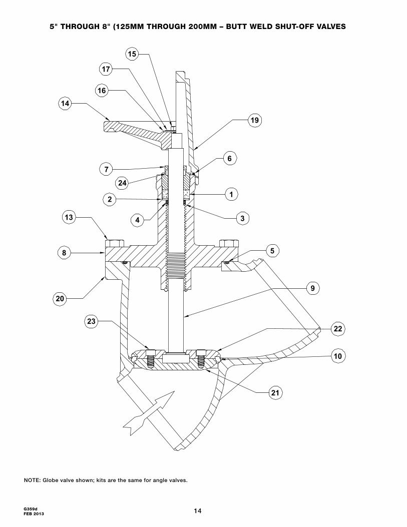
5" thRouGh 8" (125MM thRouGh 200MM – Butt Weld Shut-off vAlveS
NOTE: Globe valve shown; kits are the same for angle valves.
15
17
14
2
7
13
23
8
20
21
22
10
9
19
3
1
6
5
16
4
24
15 G359dFEB 2013
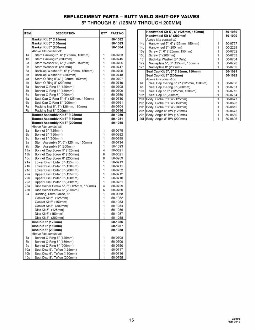
RePlACeMeNt PARtS – Butt Weld Shut-off vAlveS5" THROUGH 8" (125MM THROUGH 200MM)
ITEM DESCRIPTION QTY PART NO
Gasket Kit 5" (125mm) 50-1082Gasket Kit 6" (150mm) 50-1083Gasket Kit 8" (200mm) 50-1084Above kits consist of:
1a Stem Packing 5", 6" (125mm, 150mm) 1 50-07031b Stem Packing 8" (200mm) 1 50-07452a Stem Washer 5", 6" (125mm, 150mm) 1 50-07052b Stem Washer 8" (200mm) 1 50-07473a Back-up Washer 5", 6" (125mm, 150mm) 1 50-07063b Back-up Washer 8" (200mm) 1 50-07484a Stem O-Ring 5",6" (125mm, 150mm) 1 50-07074b Stem O-Ring 8" (200mm) 1 50-07495a Bonnet O-Ring 5" (125mm) 1 50-07085b Bonnet O-Ring 6" (150mm) 1 50-07095c Bonnet O-Ring 8" (200mm) 1 50-07506a Seal Cap O-Ring 5", 6" (125mm, 150mm) 1 50-07306b Seal Cap O-Ring 8" (200mm) 1 50-07617a Packing Nut 5", 6" (125mm, 150mm) 1 50-07047b Packing Nut 8" (200mm) 1 50-0746
Bonnet Assembly Kit 5" (125mm) 50-1080Bonnet Assembly Kit 6" (150mm) 50-1081Bonnet Assembly Kit 8" (200mm) 50-1085Above kits consist of:
8a Bonnet 5" (125mm) 1 50-06758b Bonnet 6" (150mm) 1 50-06828c Bonnet 8" (200mm) 1 50-06999a Stem Assembly 5", 6" (125mm, 150mm) 1 50-07349b Stem Assembly 8" (200mm) 1 50-109313a Bonnet Cap Screw 5" (125mm) 4 50-052113b Bonnet Cap Screw 6" (150mm) 6 50-052113c Bonnet Cap Screw 8" (200mm) 8 50-095921a Lower Disc Holder 5" (125mm) 1 50-071321b Lower Disc Holder 6" (150mm) 1 50-071121c Lower Disc Holder 8" (200mm) 1 50-075222a Upper Disc Holder 5" (125mm) 1 50-071222b Upper Disc Holder 6" (150mm) 1 50-071022c Upper Disc Holder 8" (200mm) 1 50-075123a Disc Holder Screw 5", 6" (125mm, 150mm) 4 50-072923b Disc Holder Screw 8" (200mm) 6 50-076024 Bushing, Stem Guide, 8" 1 50-0958
Gasket Kit 5" (125mm) 1 50-1082Gasket Kit 6" (150mm) 1 50-1083Gasket Kit 8" (200mm) 1 50-1084Disc Kit 5" (125mm) 1 50-1086Disc Kit 6" (150mm) 1 50-1087Disc Kit 8" (200mm) 1 50-1088
Disc Kit 5" (125mm) 50-1086Disc Kit 6" (150mm) 50-1087Disc Kit 8" (200mm) 50-1088Above kits consist of:
5a Bonnet O-Ring 5" (125mm) 1 50-07085b Bonnet O-Ring 6" (150mm) 1 50-07095c Bonnet O-Ring 8" (200mm) 1 50-0750
10a Seat Disc 5", Teflon (125mm) 1 50-071710b Seat Disc 6", Teflon (150mm) 1 50-071610c Seat Disc 8", Teflon (200mm) 1 50-0755
Handwheel Kit 5", 6" (125mm, 150mm) 50-1089Handwheel Kit 8" (200mm) 50-1090Above kits consist of:
14a Handwheel 5", 6" (125mm, 150mm) 1 50-072714b Handwheel 8" (200mm) 1 50-222915a Screw 5", 6" (125mm, 150mm) 1 50-073215b Screw 8" (200mm) 1 50-076316 Back-Up Washer (8" Only) 1 50-0764
17a Nameplate 5", 6" (125mm, 150mm) 1 50-072817b Nameplate 8" (200mm) 1 50-0759
Seal Cap Kit 5", 6" (125mm, 150mm) 50-1091Seal Cap Kit 8" (200mm) 50-1092Above kits consist of:
6a Seal Cap O-Ring 5", 6" (125mm, 150mm) 1 50-07306b Seal Cap O-Ring 8" (200mm) 1 50-076119a Seal Cap 5", 6" (125mm, 150mm) 1 50-071519b Seal Cap 8" (200mm) 1 50-075420a Body, Globe 5" BW (125mm) 1 50-067720b Body, Globe 6" BW (150mm) 1 50-069320c Body, Globe 8" BW (200mm) 1 50-081220d Body, Angle 5" BW (125mm) 1 50-067320e Body, Angle 6" BW (150mm) 1 50-068020f Body, Angle 8" BW (200mm) 1 50-0695
16G359d FEB 2013
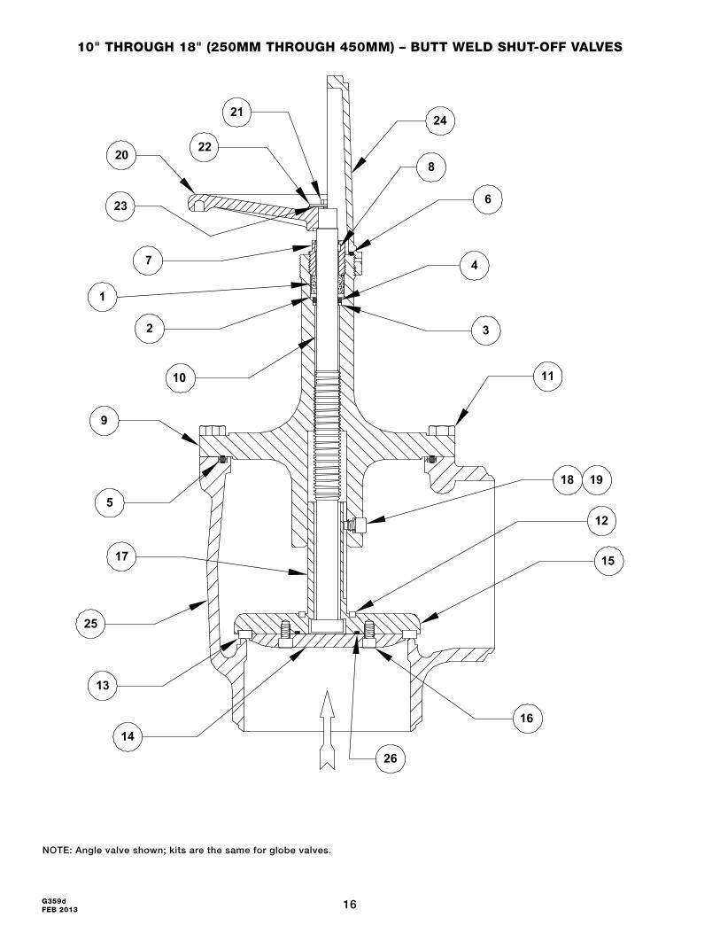
10" thRouGh 18" (250MM thRouGh 450MM) – Butt Weld Shut-off vAlveS
NOTE: Angle valve shown; kits are the same for globe valves.
14
25
13
17
5
9
10
1
23
20
2
7
22
21
16
19
11
18
15
12
3
4
8
24
6
26
17 G359dFEB 2013
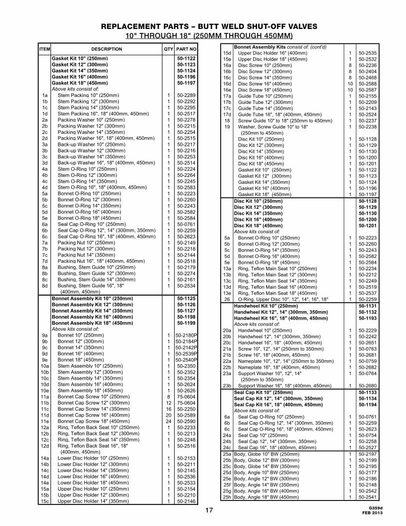
RePlACeMeNt PARtS – Butt Weld Shut-off vAlveS10" THROUGH 18" (250MM THROUGH 450MM)
ITEM DESCRIPTION QTY PART NO
Gasket Kit 10" (250mm) 50-1122Gasket Kit 12" (300mm) 50-1123Gasket Kit 14" (350mm) 50-1124Gasket Kit 16" (400mm) 50-1196Gasket Kit 18" (450mm) 50-1197Above kits consist of:
1a Stem Packing 10" (250mm) 1 50-22891b Stem Packing 12" (300mm) 1 50-22921c Stem Packing 14" (350mm) 1 50-22951d Stem Packing 16", 18" (400mm, 450mm) 1 50-25172a Packing Washer 10" (250mm) 1 50-22782b Packing Washer 12" (300mm) 1 50-22152c Packing Washer 14" (350mm) 1 50-22542d Packing Washer 16", 18" (400mm, 450mm) 1 50-25153a Back-up Washer 10" (250mm) 1 50-22173b Back-up Washer 12" (300mm) 1 50-22163c Back-up Washer 14" (350mm) 1 50-22533d Back-up Washer 16", 18" (400mm, 450mm) 1 50-25144a Stem O-Ring 10" (250mm) 1 50-22244b Stem O-Ring 12" (300mm) 1 50-22644c Stem O-Ring 14" (350mm) 1 50-22454d Stem O-Ring 16", 18" (400mm, 450mm) 1 50-25835a Bonnet O-Ring 10" (250mm) 1 50-22235b Bonnet O-Ring 12" (300mm) 1 50-22605c Bonnet O-Ring 14" (350mm) 1 50-22435d Bonnet O-Ring 16" (400mm) 1 50-25825e Bonnet O-Ring 18" (450mm) 1 50-25846a Seal Cap O-Ring 10" (250mm) 1 50-07616b Seal Cap O-Ring 12", 14" (300mm, 350mm) 1 50-22596c Seal Cap O-Ring 16", 18" (400mm, 450mm) 1 50-26237a Packing Nut 10" (250mm) 1 50-21497b Packing Nut 12" (300mm) 1 50-22187c Packing Nut 14" (350mm) 1 50-21447d Packing Nut 16", 18" (400mm, 450mm) 1 50-25188a Bushing, Stem Guide 10" (250mm) 1 50-21798b Bushing, Stem Guide 12" (300mm) 1 50-22748c Bushing, Stem Guide 14" (350mm) 1 50-21618d Bushing, Stem Guide 16", 18"
(400mm, 450mm)1 50-2534
Bonnet Assembly Kit 10" (250mm) 50-1125Bonnet Assembly Kit 12" (300mm) 50-1126Bonnet Assembly Kit 14" (350mm) 50-1127Bonnet Assembly Kit 16" (400mm) 50-1198Bonnet Assembly Kit 18" (450mm) 50-1199Above kits consist of:
9a Bonnet 10" (250mm) 1 50-2180P9b Bonnet 12" (300mm) 1 50-2184P9c Bonnet 14" (350mm) 1 50-2142P9d Bonnet 16" (400mm) 1 50-2539P9e Bonnet 18" (450mm) 1 50-2540P10a Stem Assembly 10" (250mm) 1 50-235010b Stem Assembly 12" (300mm) 1 50-235210c Stem Assembly 14" (350mm) 1 50-235410d Stem Assembly 16" (400mm) 1 50-262410e Stem Assembly 18" (450mm) 1 50-262611a Bonnet Cap Screw 10" (250mm) 8 75-060411b Bonnet Cap Screw 12" (300mm) 12 75-060411c Bonnet Cap Screw 14" (350mm) 16 50-225011d Bonnet Cap Screw 16" (400mm) 20 50-258911e Bonnet Cap Screw 18" (450mm) 24 50-259012a Ring, Teflon Back Seat 10" (250mm) 1 50-223312b Ring, Teflon Back Seat 12" (300mm) 1 50-221312c Ring, Teflon Back Seat 14" (350mm) 1 50-224812d Ring, Teflon Back Seat 16", 18"
(400mm, 450mm)1 50-2516
14a Lower Disc Holder 10" (250mm) 1 50-215314b Lower Disc Holder 12" (300mm) 1 50-221114c Lower Disc Holder 14" (350mm) 1 50-214514d Lower Disc Holder 16" (400mm) 1 50-253614e Lower Disc Holder 18" (450mm) 1 50-253315a Upper Disc Holder 10" (250mm) 1 50-215415b Upper Disc Holder 12" (300mm) 1 50-221015c Upper Disc Holder 14" (350mm) 1 50-2146
Bonnet Assembly Kits consist of: (cont'd)15d Upper Disc Holder 16" (400mm) 1 50-253515e Upper Disc Holder 18" (450mm) 1 50-253216a Disc Screw 10" (250mm) 8 50-223616b Disc Screw 12" (300mm) 8 50-240416c Disc Screw 14" (350mm) 8 50-246816d Disc Screw 16" (400mm) 10 50-258816e Disc Screw 18" (450mm) 10 50-258717a Guide Tube 10" (250mm) 1 50-215517b Guide Tube 12" (300mm) 1 50-220917c Guide Tube 14" (350mm) 1 50-214317d Guide Tube 16", 18" (400mm, 450mm) 1 50-252418 Screw Guide 10" to 18" (250mm to 450mm) 1 50-223719 Washer, Screw Guide 10" to 18"
(250mm to 450mm)1 50-2238
Disc Kit 10" (250mm) 1 50-1128Disc Kit 12" (300mm) 1 50-1129Disc Kit 14" (350mm) 1 50-1130Disc Kit 16" (400mm) 1 50-1200Disc Kit 18" (450mm) 1 50-1201Gasket Kit 10" (250mm) 1 50-1122Gasket Kit 12" (300mm) 1 50-1123Gasket Kit 14" (350mm) 1 50-1124Gasket Kit 16" (400mm) 1 50-1196Gasket Kit 18" (450mm) 1 50-1197
Disc Kit 10" (250mm) 50-1128Disc Kit 12" (300mm) 50-1129Disc Kit 14" (350mm) 50-1130Disc Kit 16" (400mm) 50-1200Disc Kit 18" (450mm) 50-1201Above kits consist of:
5a Bonnet O-Ring 10" (250mm) 1 50-22235b Bonnet O-Ring 12" (300mm) 1 50-22605c Bonnet O-Ring 14" (350mm) 1 50-22435d Bonnet O-Ring 16" (400mm) 1 50-25825e Bonnet O-Ring 18" (450mm) 1 50-2584
13a Ring, Teflon Main Seat 10" (250mm) 1 50-223413b Ring, Teflon Main Seat 12" (300mm) 1 50-221213c Ring, Teflon Main Seat 14" (350mm) 1 50-224913d Ring, Teflon Main Seat 16" (400mm) 1 50-251913e Ring, Teflon Main Seat 18" (450mm) 1 50-253726 O-Ring, Upper Disc 10", 12", 14", 16", 18" 1 50-2259
Handwheel Kit 10" (250mm) 50-1131Handwheel Kit 12", 14" (300mm, 350mm) 50-1132Handwheel Kit 16", 18" (400mm, 450mm) 50-1193Above kits consist of:
20a Handwheel 10" (250mm) 1 50-222920b Handwheel 12", 14" (300mm, 350mm) 1 50-224220c Handwheel 16", 18" (400mm, 450mm) 1 50-265121a Screw 10", 12", 14" (250mm to 350mm) 1 50-076321b Screw 16", 18" (400mm, 450mm) 1 50-268122a Nameplate 10", 12", 14" (250mm to 350mm) 1 50-075922b Nameplate 16", 18" (400mm, 450mm) 1 50-268223a Support Washer 10", 12", 14"
(250mm to 350mm)1 50-0764
23b Support Washer 16", 18" (400mm, 450mm) 1 50-2680Seal Cap Kit 10" (250mm) 50-1133Seal Cap Kit 12", 14" (300mm, 350mm) 50-1134Seal Cap Kit 16", 18" (400mm, 450mm) 50-1194Above kits consist of:
6a Seal Cap O-Ring 10" (250mm) 1 50-07616b Seal Cap O-Ring 12", 14" (300mm, 350mm) 1 50-22596c Seal Cap O-Ring 16", 18" (400mm, 450mm) 1 50-2623
24a Seal Cap 10" (250mm) 1 50-075424b Seal Cap 12", 14" (300mm, 350mm) 1 50-225824c Seal Cap 16", 18" (400mm, 450mm) 1 50-252725a Body, Globe 10" BW (250mm) 1 50-219725b Body, Globe 12" BW (300mm) 1 50-219925c Body, Globe 14" BW (350mm) 1 50-219525d Body, Angle 10" BW (250mm) 1 50-217725e Body, Angle 12" BW (300mm) 1 50-218625f Body, Angle 14" BW (350mm) 1 50-214825g Body, Angle 16" BW (400mm) 1 50-254225h Body, Angle 18" BW (450mm) 1 50-2541
18G359d FEB 2013
SeRvICe ANd MAINteNANCeHansen steel butt welding shut-off valves require practically no service or maintenance due to the combination of polished stainless steel stems and reliable O-ring stem seals plus graphite composite packing. This almost entirely eliminates stem leakage, the common ailment of shut-off valves.
To help ensure safety, verify the tightness of the packing nut whenever the position (open or closed) is changed on isolation shut-off valves before opening the system. Ensuring that the packing nut is tight helps reduce the possibility that any line or system vibration may cause a slight unseating of a closed valve.
SteM PACKINGWhen verifying the tightness of the packing nut, use an adjustable wrench. Extrusion of some black graphite packing material along the stem is normal. If the O-ring or the adjustable packing ever needs replacement as evidenced by refrigerant or oil leakage at the stem, open the valve stem firmly to the back-seat position. This separates the O-ring and packing from the system refrigerant. Remove the packing nut carefully and then use a wire hook or a small blade screwdriver to remove the packing and O-ring. Take care not to scratch the stem or bonnet sealing surfaces. Carefully install the backup washer (1½"–18" or 13mm–450mm only), new lubricated stem O-ring, stem washer, and stem packing. Tighten the packing nut only enough to give the handwheel slight turning friction.
vAlve SeAtTo inspect or replace the valve seat disc, isolate the valve from the system and safely pump out all refrigerant to zero pressure with the stem open at least one turn. Evenly loosen all bolts one to two turns. Using a screwdriver, break the seal between the bonnet and valve body, proceeding cautiously to avoid any refrigerant which may still remain inside the valve body. Remove the bonnet bolts and bonnet assembly, being careful not to damage the Teflon seat disc surface. If the seat surface in the body is marred, it may be possible to repair the seat by polishing with emery paper.
If the Teflon seat disc is damaged, replace the entire disc assembly ½" (13mm) thru 4" (100mm) by first removing the ball retainer spring, ball bearings and anti-spin O-ring. Install a new disc assembly including anti-spin O-ring. Alternately, use a lathe to take a 1⁄64" (0.4 mm) by 45° surface cut on the Teflon seat. The 5" (125mm) thru 18" (450mm) Teflon seats can be replaced by disassembling the disc holder by loosening and removing the disc screws. Replace the Teflon ring, the upper disc O-ring in 10" (250mm) and above, and reassemble the disc.
Replace body gasket or O-ring and reassemble bonnet into body using care not to damage Teflon seat surface. Be careful not to pinch the O-ring. If necessary, retain O-ring in O-ring groove by using a suitable O-ring grease. Ensure the stem is opened at least several turns.
Hansen assembles valves with bonnet cap screws factory tightened as follows: 1⁄2" to 11⁄4" (13mm to 32mm)– 30 ft-lb (41 Nm); 11⁄2" (40mm) and 2" (50mm)–40 ft-lb (54 Nm); 21⁄2" (65mm) and 3" (80mm)–60 ft-lb (81 Nm); 4" (100mm)– 180 ft-lb (244 Nm); and 5" to 18" (125mm to 450mm)– 200 ft-lb (271Nm). Test the valve for leaks before returning it to service.
tRouBleShootING vAlve leAKSOn the rare occasion when a small valve leak is discovered, the following procedures may help:
Stem seal leaks – The possibility of this occurrence is based on many factors, such as frequency of use, exercising, debris or rust on stem, etc. First, simply tighten the packing nut to see if this eliminates the leak. If not, back seat the valve or isolate it entirely from the refrigeration system. See Stem Packing section of this bulletin.
Bonnet gasket leaks – If a gasket leak is discovered at the bonnet-to-body interface, first bring the pressure in the valve to zero pressure and check the bonnet bolt tightness. If the leak persists, isolate the valve from the refrigeration system and disassemble the valve. Check the gasket sealing surfaces on the bonnet and valve body for scratches or gouges. These scratches can sometimes be polished smooth. Install a new gasket and reassemble the valve. Evenly tighten all bolts to properly seat the bonnet. Repeat the pressure test.
Bonnet O-ring leaks – Valves 5" (125mm) and larger use bonnet O-rings. If a leak is discovered at the bonnet-to-body interface, first bring the pressure in the valve to zero pressure and check the bonnet bolt torque. The torque recommendations are provided below. If the leak persists, isolate the valve from the refrigeration system and disassemble the valve. Check for debris on the surfaces of the bonnet and O-ring groove in the valve body. Check for scratches and polish the surfaces. Clean and check the O-ring for cuts, cracks and embedded debris. Check the bonnet and valve surface for flatness. Occasionally, the edge of the bonnet on the valve body is struck or dropped which could damage or raise the sealing surface of the bonnet. This prevents the two sealing surfaces from being completely engaged. Remove the raised edge. Also, if not carefully re-assembled, the bonnet may have been slightly askew, preventing proper sealing. Before reassembling the valve, clean the sealing surfaces and O-ring apply suitable grease to the O-ring. Install the bonnet, making sure the stem is open several turns. Evenly tighten, then torque the bonnet bolts to the specified value below. Pressure test the valve to check for leaks.
19 G359dFEB 2013
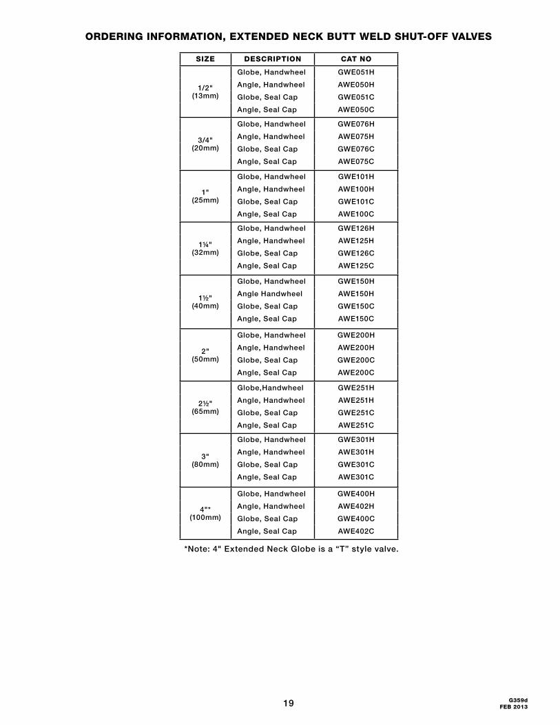
oRdeRING INfoRMAtIoN, exteNded NeCK Butt Weld Shut-off vAlveS
*Note: 4" Extended Neck Globe is a “T” style valve.
SIZe deSCRIPtIoN CAt No
1/2" (13mm)
Globe, Handwheel GWE051H
Angle, Handwheel AWE050H
Globe, Seal Cap GWE051C
Angle, Seal Cap AWE050C
3/4" (20mm)
Globe, Handwheel GWE076H
Angle, Handwheel AWE075H
Globe, Seal Cap GWE076C
Angle, Seal Cap AWE075C
1" (25mm)
Globe, Handwheel GWE101H
Angle, Handwheel AWE100H
Globe, Seal Cap GWE101C
Angle, Seal Cap AWE100C
1¼" (32mm)
Globe, Handwheel GWE126H
Angle, Handwheel AWE125H
Globe, Seal Cap GWE126C
Angle, Seal Cap AWE125C
1½" (40mm)
Globe, Handwheel GWE150H
Angle Handwheel AWE150H
Globe, Seal Cap GWE150C
Angle, Seal Cap AWE150C
2" (50mm)
Globe, Handwheel GWE200H
Angle, Handwheel AWE200H
Globe, Seal Cap GWE200C
Angle, Seal Cap AWE200C
2½" (65mm)
Globe,Handwheel GWE251H
Angle, Handwheel AWE251H
Globe, Seal Cap GWE251C
Angle, Seal Cap AWE251C
3" (80mm)
Globe, Handwheel GWE301H
Angle, Handwheel AWE301H
Globe, Seal Cap GWE301C
Angle, Seal Cap AWE301C
4"* (100mm)
Globe, Handwheel GWE400H
Angle, Handwheel AWE402H
Globe, Seal Cap GWE400C
Angle, Seal Cap AWE402C
20G359d FEB 2013
Hansen Technologies Corporation400 Quadrangle Drive, Suite FBolingbrook, Illinois 60440 USATel: 630.325.1565 Fax: 630.325.1572 Toll: 866.4HANSEN Email: [email protected] Web: www.hantech.comUSA ∙ Asia ∙ Europe ∙ India ∙ LatinAmerica ∙ MiddleEast© 2013 Hansen Technologies Corporation
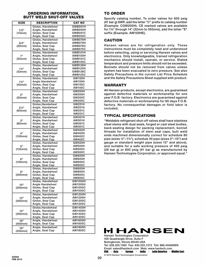
to oRdeRSpecify catalog number. To order valves for 600 psig (41 bar g) SWP, add the letter “C” prefix to catalog number (Example: CGW200H). CE marked valves are available for 1¼" through 14" (32mm to 350mm), add the letter "E" suffix (Example: AW150HE).
CAutIoNHansen valves are for refr igerat ion only. These instructions must be completely read and understood before selecting, using or servicing Hansen valves and electronics. Only knowledgeable, trained refrigeration mechanics should install, operate, or service. Stated temperature and pressure limits should not be exceeded. Bonnets should not be removed from valves unless system has been evacuated to zero pressure. See also Safety Precautions in the current List Price Schedule and the Safety Precautions Sheet supplied with product.
WARRANtYAll Hansen products, except electronics, are guaranteed against defective materials or workmanship for one year F.O.B. factory. Electronics are guaranteed against defective materials or workmanship for 90 days F.O.B. factory. No consequential damages or field labor is included.
tYPICAl SPeCIfICAtIoNS“Weldable refrigerant shut-off valves shall have stainless steel stems with dual seals, forged or cast steel bodies, back-seating design for packing replacement, bonnet threads for installation of stem seal caps, butt weld ends machined dimensionally correct for schedule 80 pipe (sizes ½"–1½"), schedule 40 pipe (sizes 2"–10") and gauge or standard weight pipe (sizes 12" and above), and suitable for a safe working pressure of 400 psig (28 bar g) or 600 psig (41 bar g) as manufactured by Hansen Technologies Corporation, or approved equal.”
SIZe deSCRIPtIoN CAt No
1/2" (13mm)
Globe, Handwheel GWB051HAngle, Handwheel AWB050HGlobe, Seal Cap GWB051CAngle, Seal Cap AWB050C
3/4" (20mm)
Globe, Handwheel GWB076HAngle, Handwheel AWB075HGlobe, Seal Cap GWB076CAngle, Seal Cap AWB075C
1" (25mm)
Globe, Handwheel GWB101HAngle, Handwheel AWB100HGlobe, Seal Cap GWB101CAngle, Seal Cap AWB100C
1¼" (32mm)
Globe, Handwheel GWB126HAngle, Handwheel AWB125HGlobe, Seal Cap GWB126CAngle, Seal Cap AWB125C
1½" (40mm)
Globe, Handwheel GW150HAngle Handwheel AW150HGlobe, Seal Cap GW150CAngle, Seal Cap AW150C
2" (50mm)
Globe, Handwheel GW200HAngle, Handwheel AW200HGlobe, Seal Cap GW200CAngle, Seal Cap AW200C
2½" (65mm)
Globe,Handwheel GW251HAngle, Handwheel AW251HGlobe, Seal Cap GW251CAngle, Seal Cap AW251C
3" (80mm)
Globe, Handwheel GW301HAngle, Handwheel AW301HGlobe, Seal Cap GW301CAngle, Seal Cap AW301C
4" (100mm)
Globe, Handwheel GW402HAngle, Handwheel AW402HGlobe, Seal Cap GW402CAngle, Seal Cap AW402C
5" (125mm)
Globe, Handwheel GW500HAngle, Handwheel AW500HGlobe, Seal Cap GW500CAngle, Seal Cap AW500C
6" (150mm)
Globe, Handwheel GW600HAngle, Handwheel AW600HGlobe, Seal Cap GW600CAngle, Seal Cap AW600C
8" (200mm)
Globe, Handwheel GW800HAngle, Handwheel AW800HGlobe, Seal Cap GW800CAngle, Seal Cap AW800C
10" (250mm)
Globe, Handwheel GW1000HAngle Handwheel AW1000HGlobe, Seal Cap GW1000CAngle, Seal Cap AW1000C
12" (300mm)
Globe, Handwheel GW1200HAngle, Handwheel AW1200HGlobe, Seal Cap GW1200CAngle, Seal Cap AW1200C
14" (350mm)
Globe,Handwheel GW1400HAngle, Handwheel AW1400HGlobe, Seal Cap GW1400CAngle, Seal Cap AW1400C
16" (400mm)
Angle, Handwheel AW1600HAngle, Seal Cap AW1600C
18" (450mm)
Angle, Handwheel AW1800HAngle, Seal Cap AW1800C
oRdeRING INfoRMAtIoN, Butt Weld Shut-off vAlveS