AW-I - Price Industries · AW-I-1 v001 Typical Applications ... which is different from the main...
24
AW-I Indirect Fired Units
Transcript of AW-I - Price Industries · AW-I-1 v001 Typical Applications ... which is different from the main...

AW-IIndirect Fired Units
AW-I-1v001
Typical ApplicationsDrum and tube heat exchangers are an
essential product for heating occupied
commercial and industrial spaces during
winter months. Mounted indoors or
outside on a slab or roof mounted on a
curb the Price AW-I units are an excellent
option for providing conditioned air to
hospitals, hotels, condominiums, shopping
malls, and factories.
AW-I units can incorporate DX cooling,
energy recovery, and customized controls
to meet application specific needs.
Price Mechanical offers complete custom
designs to compete in the demanding
market and to match your needs and
specifications.
KEY FEATURES
For demanding indirect fired applications, Price offers the AW-I series with three and four pass stainless steel drum and tube heat exchangers.
The output range for these units is:
•3-Pass: 250-4,000 MBH
•4-Pass: 250-6,000 MBH
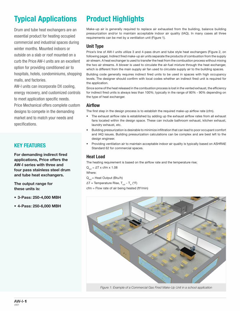
Product HighlightsMake-up air is generally required to replace air exhausted from the building, balance building pressurization and/or to maintain acceptable indoor air quality (IAQ). In many cases all three requirements can be met by a ventilation unit (Figure 1).
Unit TypePrice’s line of AW-I units utilize 3 and 4-pass drum and tube style heat exchangers (Figure 2, on following page). Indirect fired make-up air units separate the products of combustion from the supply air stream. A heat exchanger is used to transfer the heat from the combustion process without mixing the two air streams. A blower is used to circulate the air-fuel mixture through the heat exchanger, which is different from the main supply air fan used to circulate supply air to the building spaces.
Building code generally requires indirect fired units to be used in spaces with high occupancy levels. The designer should confirm with local codes whether an indirect fired unit is required for the application.
Since some of the heat released in the combustion process is lost in the vented exhaust, the efficiency for indirect fired units is always less than 100%; typically in the range of 80% - 90% depending on the type of heat exchanger.
AirflowThe first step in the design process is to establish the required make-up airflow rate (cfm).
• The exhaust airflow rate is established by adding up the exhaust airflow rates from all exhaust fans located within the design space. These can include bathroom exhaust, kitchen exhaust, laundry exhaust, etc.
• Building pressurization is desirable to minimize infiltration that can lead to poor occupant comfort and IAQ issues. Building pressurization calculations can be complex and are best left to the design engineer.
• Providing ventilation air to maintain acceptable indoor air quality is typically based on ASHRAE Standard 62 for commercial spaces.
Heat LoadThe heating requirement is based on the airflow rate and the temperature rise;
Qout = ΔT x cfm x 1.08
Where:
Qout = Heat Output (Btu/h)
ΔT = Temperature Rise, Tout - Tin (°F)
cfm = Flow rate of air being heated (ft³/min)
Figure 1: Example of a Commercial Gas Fired Make-Up Unit in a school application

AW-I-2For more information visit www.priceindustries.comv001
The inlet temperature is typically the winter design temperature, and can be determined from weather data in the ASHRAE Fundamentals Handbook. Price units can operate with supply air temperatures down to -40°F.
The discharge temperature will depend on the application. In many cases, the design intent is to provide neutral air to the occupied space, so 70 to 75°F is common.
The temperature rise (Tout – Tin) can be up to 110°F for indirect fired units.
Using a Higher Heating Value (HHV) of 1,000 Btu/ft³ for natural gas, the required gas flow rate at design conditions can be calculated as follows;
Natural gas flow rate (cubic feet per hour [CFH]) = heat input (Btu/h)/1,000 Btu/ft³
The natural gas flow rate or heat input can be used for sizing gas piping to the unit. It is not recommended that the gas pipe connection size be used to size the piping. The pipe size will depend on the pressure loss of the field piping, the gas flow rate and the available gas inlet pressure.
Contact the factory for oil-burning applications.
AltitudeAltitude will impact the heat capacity of the unit because less dense air has less oxygen for combustion. The capacity of units is based on sea level, and will be acceptable up to 2,000 ft. The unit capacity will be de-rated by 4% for every 1,000 ft. above 2,000 ft. For example, a unit selected for Denver at 5,000 ft. elevation will be de-rated by 12% [4% x (5,000 ft. - 2,000 ft.)/1,000 ft.].
Capacity ControlThe make-up air heating capacity is based on design conditions. During periods when the ambient temperature is warmer than design conditions, the heating capacity will be too great and the unit will need some form of capacity
control. On-off control will cycle the heat on and off based on the actual load. For periods when only 50% capacity is required, the unit will operate for 50% of the time. While inexpensive, this is not a recommended capacity control method. The wide changes in supply air temperature (no heat to full heat) provided to the space could lead to poor occupant satisfaction. It is also demanding on the equipment and will likely reduce the useful life.
Price units are provided with high turndown modulating controls. Modulating controls will maintain supply air set point down to minimum capacity. Minimum capacity is established by the turndown ratio. For example a make-up air unit with 100°F temperature rise and 10:1 turndown can operate down to 10°F rise before the unit will cycle on and off to meet the heating load.
Gas TrainGas trains are designed to meet strict gas code requirements. They all have the following basic components:
• Field Installed Main Manual Gas Shut Off Valve – This valve is field installed outside the unit so the gas can be shut off to all components along with the make-up air unit. This is much the same as an electrical disconnect switch. For shipping reasons, it cannot be factory installed. While it is a requirement of the gas code and should be installed by the contractor, it is also a good idea to show this detail on the drawings.
• Main Line Gas Pressure Regulator Valve – This valve maintains the gas pressure at the make-up air unit within rated parameters.
• Main Line Automatic Gas Valves – These are the main shut off valves that open when heat is required. They are generally two position on-off type. The requirements change depending on the furnace size. Under 1 million Btu/h, two redundant gas valves are acceptable.
• Main Line Modulating Valve – This is the valve that permits modulating heat control. As the unit’s controller translates the change in required supply air output temperature, the modulating valve adjusts the fuel flow rate into the burner.
• Main Firing Manual Shut Off Valve – This valve allows a service technician to shut off gas to the burner, but not the pilot burner.
• Pilot Line Manual Shut Off Valve – This valve allows a service technician to shut off gas to the pilot, but not the main burner.
• Pilot Gas Valve – The pilot lets a small amount of fuel enter the burner during start up. This fuel is typically ignited with an electronic ignition system. On larger burners, a pilot flame is used to light the main flame. Once the pilot is lit and flame is proven, the main gas valves will open.
The exact design of the gas train will depend on the model and size. For smaller products, some of the components listed above are combined into a single piece.
Gas BurnersIndirect fired burner assemblies include either forced draft or induced draft burners. Forced draft burners have combustion air blowers located at the inlet of the furnace and pressurize the furnace while maintaining the correct air fuel ratio. AW-I units have forced draft burner assemblies.
An optional induced draft blower will place combustion air blowers located at the exhaust point of the furnace. Induced draft blowers are an option to be used when overcoming excess vent static pressure. AW-I 4-pass units can be equipped with induced draft burners.
Both forced draft and induced draft units must modulate the combustion air quantity as the gas valve modulates to maintain the correct fuel-air ratio. This can be done mechanically (dampers) or electronically (fan speed).
Figure 2: Example of airflow for an Indirect Fired Unit

AW-I-3v001
CondensationThe products of combustion are mainly carbon dioxide and water. Due to the heat available, water is formed as a gas. As heat is removed from the products of combustion, water may condense. This condensate is very acidic and can lead to severe corrosion of the furnace. Price furnaces are constructed from 409 stainless steel to help minimize the adverse effects of corrosion.
In addition, the furnaces have a drain connection to remove the condensate. The drain connection will require a field provided trap. Indoor applications will require access to a drain, such as a floor drain. Outdoor applications may require draining and capping of the trap, or heat tracing in freezing conditions. Some jurisdictions may require additional treatment of the furnace condensate. Check with the local codes.
VentingIndirect fired units require combustion gas venting. Units for outdoor applications come complete
and require no further design considerations. Indoor units will require a combustion air source and a type “B” vent stack. The total equivalent length cannot exceed 50 ft (Figure 3).
Fan SelectionFan selection is based on the required airflow (cfm) and the total static pressure (in. w.c.). The total static pressure is established as follows;
Total Static Pressure (TSP) = External Static Pressure (ESP) + Internal Static Pressure (ISP) (in. w.c.)
The ESP is calculated by the designer based on the airflow rate and duct design. This process is well documented in the ASHRAE handbooks. It should cover all static losses from the discharge of the unit to the space being served.
The ISP is calculated based on pressure drops of the components within the make-up air unit, including filters, dampers, heat exchangers, cabinet losses, etc. These losses are established through testing. Note that Price uses the average
filter pressure drop to estimate the ISP. Clean filters will allow slightly more air to pass through, while dirty filters will allow slightly less.
With the TSP and supply airflow established, the fan curves for the available fan models are calculated using the vendor supplied fan selection software. The actual fan selection is a judgment that balances performance, efficiency and operating position on the fan curve (Figure 4). Standard rubber-in-shear style isolators are provided, with options for 1” or 2” spring isolation as required.
Mixing BoxIndirect fired units can be supplied with mixing boxes that allow return air to be mixed with outdoor air. Some possible applications for a make-up air unit with a mixing box are (Figure 5):
Airside free cooling (economizer)
• The unit can be selected with an airflow rate greater than the minimum ventilation rate. In cold weather, the mixing box will only
Figure 3: Typical venting system for vertical venting
Rain Cap
Roof Flashing
Firestop/Support
Hangar Strap
Unit Condensation Drain (Install According to
Local Codes)
Firestop

AW-I-4For more information visit www.priceindustries.comv001
• introduce the minimum ventilation rate. The balance of the supply airflow will be return air. During periods where airside free cooling is desirable, the unit will increase the outdoor air to provide free cooling. Price units come standard with enthalpy based economizer controls when a mixing box is supplied. The control has a field adjustable minimum outdoor air set point.
Varying outdoor ventilation requirements
• For applications where the ventilation rate changes throughout the day, a mixing box can be used to reduce unnecessary outdoor ventilation. An example might be when some exhaust fans are on a time schedule. When all exhaust fans are operating, the unit will run at 100% outdoor air. During periods when some of the exhaust fans are off and the ventilation requirement is reduced, the amount of outdoor air can be reduced.
• Where the primary purpose for supplying outdoor air is to improve indoor air quality, Demand Control Ventilation (DCV) can be employed. Typically carbon dioxide levels are measured and the amount of outdoor air is varied to maintain the acceptable carbon dioxide level. DCV will only introduce (and thus heat) the minimum necessary amount of outdoor air.
ControlsPrice units come standard with unit mounted controls. Unit controls include;
• Unit On-Off
• Heat Off-Enable
• Supply air temperature set point
A duct mounted temperature sensor is supplied loose for field installation in the ductwork approximately 10 feet from the unit supply air opening. A remote control panel is also available, which can be mounted inside the building for ease of operation.
Unit PlacementPrice units can be installed outdoors on a curb, housekeeping pad or sleepers. Designers should ensure there is suitable structural support for the weight of the unit. Supply air connections can be either down flow, up flow, side discharge or end discharge. Units should have enough space around them to allow for proper service, and should avoid having combustible materials too close to the unit. Specific distances are called out on the rating plate, but using a minimum of 12 inches is generally acceptable.
The controls cabinet will require at least 3 feet of access. Access doors can be ordered for either side of the unit (left or right hand). A service distance of 24 inches opposite the main access side is desirable, but the unit can be placed closer to obstructions if necessary.
Example of a Single Fan
Figure 4: Fan Curve
Figure 5: Mixing Box
8
7
6
5
4
3
2
1
0
1.4
1.2
1
0.8
0.6
0.4
0.2
0
Bra
ke P
ow
er (
hp
)
Volume (cfm)
Sta
tic
Pres
sure
(in
. w.c
.)
0 2000 4000 6000 8000 10000 12000 14000
Inputs: Altitude: 0 | Airflow: 8000 | TSP: 1.10 | Fan Size: 18/18
Legend: Fan Curve System Curve Brake Power Curve

AW-I-5v001
AW-I Components
100% Outdoor Air Hood and Inlet• 18 gauge painted galvanized steel
• Half inch expanded metal bird screen
• Motorized two position damper
- Optional Modulating inlet damper
- Optional Inlet Louver
Filters• 2 inch filter rack
• MERV 8, hi-temp and washable media filters available
• MERV 14 Filters available – Contact factory
Fans• High efficiency forward curved DWDI fans
• Greasable pillow block bearings
• Adjustable motor mount base
• Fan skid mounted on RIS isolators, spring isolation optional
Furnace• Grade 409 stainless steel 3 pass and 4 pass
drum and tube style heat exchanger (Grades 304 and 316 stainless steel optional)
• Up to 15 to 1 turndown
• Operates down to -40°F ambient
• Single point piping connection
• CSA certified for Canada and USA
Cabinet – 2 standard designs available • 18 gauge painted galvanized steel single
wall construction
- Panel seams are turned inward for clean appearance
- 2 inch, 1 ½ lb. density glass fiber insulation (pinned and glued)
• 20 gauge painted galvanized steel casing with 22 gauge liner
- 2 inch foam injected panels
- Offers lower leakage than glass fiber insulation
- Increased rigidity
- 2 inch, 1 ½ lb. density glass fiber insulation in heat exchanger section
Dampers• Triple-vee roll formed galvanized steel
blades
• Optional low leak aluminum airfoil or insulated airfoil dampers
Doors• Double walled construction designed with
similar construction to unit cabinet
- Either 2 inch, 1½ lb. density glass fiber insulation or 2 inch foam injected panels
• Hinged doors supplied for fan, filter, and controls sections
Controls• Standalone controls with Honeywell T775
and Zelio
• Optional DDC controls can be integrated into building automation system
Disconnect• Non-fused and fused disconnect available
• Single point power connection
Base• 6" Formed Steel base frame
• 4" and 6" Structural Steel base frame
Fans
Filters
100% Outdoor Air Hood
Furnace
Cabinet
Controls
DoorsDisconnect
Product Features
Motor

AW-I-6For more information visit www.priceindustries.comv001
Product OptionsFan IsolationFans used in Price MUA units come standard with Rubber in Shear (RIS) isolation. Price offers 1 or 2 inch deflection spring isolation for applications where sound and vibration issues are of concern.
Motor TypesThe supply fan motor can be upgraded from high efficiency Open Drip Proof (ODP) to high efficiency Total Enclosed Fan Cooled (TEFC) for improved reliability.
Mixing BoxIndirect fired units can incorporate mixing boxes that allow recirculation from the building. The mixing box integrates motorized modulating dampers and enthalpy based economizer controls. Demand Control Ventilation (CO2 monitoring) is also available.
LouversFor a cleaner appearance, louvers are available to replace the outdoor air hood. The louvers are constructed of either galvanneal steel or aluminum, and include rain gutters in each blade to channel away rain and reduce entrainment.
Top Inlet Mushroom HoodWhere an end wall outdoor air inlet is not convenient, a top mounted mushroom hood is available. The hood is designed to minimize entrainment and includes a ½ inch expanded metal bird screen.
FM and GAP Style Gas Train For customers who require additional quality and ruggedness, Price MUA units can utilize FM Style (Factory Mutual) and GAP (formerly IRI) style components.
4-Pass Heat ExchangerFor applications that require the exhaust flue on the same side as the controls, (such as indoor unit mounting) or where higher capacity is necessary the Price AW-I 4-Pass heat exchanger is an ideal solution.
Remote Control PanelFor ease of operation, a remote control panel is available. The panel includes on-off, heat enable and supply air temperature set point control. A service switch is located in the unit control cabinet to improve serviceability by allowing local override during servicing. DDC controls can include a wall mounted room controller upon request.
Additional Options: timeclock, panel-mounted controller, and additional monitoring lights.
Dampers Low leakage aluminum airfoil dampers are available. The improved leakage rate reduces infiltration and heat loss during periods when the unit is shut down. The low leak rating is accomplished by rubber blade and jamb seals and a stiffer blade profile. For even better performance, the blades can be insulated with expanded polyurethane foam, that further reduces heat loss during shut down periods.
FiltersPrice MUA units include a 2 inch filter rack. Metal filters, high temperature filters and replaceable media filters with removable frames are all available for improved indoor air quality, 4 inch MERV 14 secondary filters can be installed for added filtration.
Integral DX CoolingFor applications where cooling is as important as heating, Price offers integral DX cooling. Price offers integrated air cooled DX cooling options from 5 tons up to 130 tons, and integral water cooled DX cooling options up to 65 tons.
Filter GaugesTo improve maintenance, magnehelic, digihelic and photohelic filter gauges are available.
Roof CurbsRoof curbs are an excellent way to install Price MUA units on a roof, particularly for downflow applications. Price curbs are designed to fit perfectly with our units, and include wood nailer strips to tie in the roofing membrane. Price curbs also have internal support rails to hold field supplied flanged duct collars for fast and easy installation. The curbs can be shipped in advance of the units with the duct collars installed prior to unit delivery.
Supply Fan Variable Frequency Drives (VFDs)VFDs can help reduce electrical and gas consumption during periods when the full outdoor air ventilation rate is not required. All Price MUAs can have VFDs that allow 50% supply air turndown for drum and tube units.
Chilled Water CoolingWhere cooling is required and chilled water is available, Price can provide chilled water coils. The coils will be mounted over a drain pan.
DDC ControlsIntegrating HVAC equipment into a building automation system can allow remote control, quick recognition of issues and improved control for performance and savings. Price units can be supplied with BACnet connectivity when used in conjunction with DDC controls.

AW-I-7v001
Performance Data
Indirect 3-Pass Drum and Tube (AW-I-3-25 to AW-I-3-75)
Model Number
Heat Input(MBH)
Heat Output(MBH)
Airflow(cfm)
Temp Rise(F)
HorsepowerFan Size
(FC)ESP (in. w.c.)0.25 0.5 0.75 1.0 1.25 1.5
AW-I-3-25
313 250 2,104 110 1.0 1.1 1.2 1.3 1.4 1.5 9 313 250 2,315 100 1.2 1.3 1.4 1.5 1.7 1.8 9 313 250 2,572 90 1.2 1.3 1.5 1.6 1.8 1.9 10 313 250 2,894 80 1.5 1.7 1.8 2.0 2.2 2.3 10 313 250 3,307 70 2.1 2.2 2.4 2.6 2.7 2.9 10 313 250 3,858 60 1.9 2.1 2.4 2.6 2.8 3.0 12
AW-I-3-30
360 288 2,424 110 1.0 1.1 1.3 1.4 1.6 1.7 10 360 288 2,667 100 1.2 1.4 1.5 1.7 1.8 2.0 10 360 288 2,963 90 1.5 1.7 1.8 2.0 2.2 2.3 10 360 288 3,333 80 1.3 1.5 1.7 1.9 2.1 2.3 12 360 288 3,810 70 1.7 1.9 2.1 2.3 2.6 2.8 12 360 288 4,444 60 2.3 2.5 2.8 3.0 3.3 3.6 12
AW-I-3-40
500 400 3,367 110 1.6 1.7 1.9 2.0 2.2 2.3 12/9 500 400 3,704 100 1.6 1.8 2.0 2.2 2.5 2.7 12 500 400 4,115 90 2.0 2.2 2.4 2.7 2.9 3.1 12 500 400 4,630 80 2.5 2.8 3.0 3.3 3.5 3.8 12 500 400 5,291 70 2.4 2.7 3.0 3.4 3.7 4.1 15 500 400 6,173 60 2.8 3.1 3.1 3.9 4.3 4.8 18
AW-I-3-50
625 500 4,209 110 2.0 2.2 2.4 2.7 2.9 3.2 12 625 500 4,630 100 2.4 2.7 2.9 3.2 3.4 3.7 12 625 500 5,144 90 2.1 2.4 2.7 3.0 3.4 3.7 15 625 500 5,787 80 2.8 3.0 3.3 3.6 3.9 4.3 15 625 500 6,614 70 2.8 3.2 3.5 3.9 4.4 4.8 18 625 500 7,716 60 4.0 4.3 4.7 5.1 5.5 5.7 18
AW-I-3-65
813 650 5,471 110 3.5 3.7 4.0 4.2 4.5 4.8 12 813 650 6,019 100 2.8 3.1 3.4 3.7 4.0 4.3 15 813 650 6,687 90 3.5 3.9 4.2 4.5 4.8 5.1 15 813 650 7,523 80 3.4 3.8 4.1 4.5 4.9 5.3 18 813 650 8,598 70 4.5 5.0 5.4 5.8 6.2 6.6 18 813 650 10,031 60 5.2 5.8 6.4 7.0 7.6 8.0 20
AW-I-3-75
938 750 6,313 110 3.1 3.4 3.7 4.0 4.3 4.6 15 938 750 6,944 100 3.8 4.2 4.5 4.9 5.2 5.5 15 938 750 7,716 90 4.9 5.3 5.6 6.0 6.4 6.7 15 938 750 8,681 80 4.6 5.1 5.5 5.9 6.3 6.9 18 938 750 9,921 70 6.2 6.7 7.2 7.7 8.2 8.7 18 938 750 11,574 60 7.1 7.7 8.3 9.1 9.8 10.5 20
For dimensional data please see page 13.Performance and Dimensions subject to change.

AW-I-8For more information visit www.priceindustries.comv001
Performance Data
Indirect 3-Pass Drum and Tube (AW-I-3-85 to AW-I-3-400)
Model Number
Heat Input(MBH)
Heat Output(MBH)
Airflow (cfm)
Temp Rise (F)
HorsepowerFan Size
(FC)ESP (in. w.c.)0.25 0.5 0.75 1.0 1.25 1.5
AW-I-3-85
1,063 850 7,155 110 3.1 3.6 4.0 4.4 4.9 5.4 Twin 12 1,063 850 7,870 100 3.7 4.2 4.7 5.2 5.7 6.2 Twin 12 1,063 850 8,745 90 4.6 5.1 5.6 6.2 6.7 7.3 Twin 12 1,063 850 9,838 80 3.7 4.4 5.1 5.9 6.6 7.4 Twin 18 1,063 850 11,243 70 4.6 5.3 6.1 6.9 7.7 8.6 Twin 18 1,063 850 13,117 60 6.1 6.8 7.6 8.5 9.4 10.3 Twin 18
AW-I-3-100
1,250 1,000 8,418 110 3.0 3.7 4.3 5.0 5.7 6.4 Twin 18 1,250 1,000 9,259 100 3.4 4.1 4.8 5.5 6.2 7.0 Twin 18 1,250 1,000 10,288 90 4.0 4.7 5.4 6.2 7.0 7.8 Twin 18 1,250 1,000 11,574 80 4.8 5.5 6.3 7.1 8.0 8.8 Twin 18 1,250 1,000 13,228 70 6.2 6.9 7.7 8.6 9.5 10.4 Twin 18 1,250 1,000 15,432 60 8.0 8.7 9.5 10.3 11.2 12.1 Twin 18
AW-I-3-125
1,567 1,254 10,552 110 4.6 5.1 5.6 6.3 7.1 7.8 Twin 15 1,567 1,254 11,607 100 5.5 6.2 6.7 7.3 8.0 8.8 Twin 15 1,567 1,254 12,897 90 5.3 5.9 6.7 7.5 8.4 9.3 Twin 18 1,567 1,254 14,509 80 6.7 7.4 8.1 8.9 9.8 10.7 Twin 18 1,567 1,254 16,582 70 8.8 9.7 10.5 11.4 12.2 13.1 Twin 18 1,567 1,254 19,346 60 12.3 13.3 14.4 15.4 16.5 17.4 Twin 18
AW-I-3-150
1,876 1,500 12,630 110 6.6 7.3 7.9 8.5 9.1 9.9 Twin 15 1,876 1,500 13,893 100 6.1 6.8 7.5 8.3 9.2 10.1 Twin 18 1,876 1,500 15,436 90 7.5 8.4 9.1 9.9 10.7 11.6 Twin 18 1,876 1,500 17,366 80 9.7 10.6 11.6 12.5 13.3 14.2 Twin 18 1,876 1,500 19,847 70 13.0 14.1 15.2 16.2 17.3 18.3 Twin 18 1,876 1,500 23,154 60 11.6 12.9 14.2 15.5 16.9 18.3 Twin 22
AW-I-3-175
2,188 1,750 14,731 110 6.9 7.6 8.4 9.1 10.0 10.9 Twin 18 2,188 1,750 16,204 100 8.4 9.1 10.1 10.9 11.7 12.6 Twin 18 2,188 1,750 18,004 90 10.5 11.5 12.4 13.4 14.3 15.1 Twin 18 2,188 1,750 20,255 80 10.9 12.1 13.5 14.9 16.1 17.3 Twin 20 2,188 1,750 23,148 70 11.6 12.9 14.2 15.5 16.9 18.3 Twin 22 2,188 1,750 27,006 60 16.3 17.6 19.1 20.5 22.0 23.5 Twin 22
AW-I-3-200
2,500 2,000 16,835 110 8.5 8.4 10.3 11.1 12.0 12.8 Twin 18 2,500 2,000 18,519 100 10.3 11.3 12.3 13.3 14.3 15.3 Twin 18 2,500 2,000 20,576 90 8.1 10.3 11.5 12.8 14.2 15.5 Twin 22 2,500 2,000 23,148 80 10.1 11.3 12.5 13.8 15.1 16.5 Twin 22 2,500 2,000 26,455 70 13.4 14.7 16.0 17.4 18.8 20.2 Twin 22 2,500 2,000 30,864 60 15.1 16.7 18.4 20.0 21.7 23.6 Twin 25
AW-I-3-250
3,125 2,500 21,044 110 8.4 9.5 10.7 11.9 13.2 14.5 Twin 22 3,125 2,500 23,148 100 10.1 11.3 12.5 13.8 15.1 16.5 Twin 22 3,125 2,500 25,720 90 10.5 11.9 13.4 15.0 16.8 18.5 Twin 25 3,125 2,500 28,935 80 13.2 14.7 16.3 17.9 19.6 21.4 Twin 25 3,125 2,500 33,069 70 17.4 19.1 20.9 22.6 24.4 26.3 Twin 25 3,125 2,500 38,580 60 24.5 26.6 28.6 30.6 32.6 34.7 Twin 25
AW-I-3-300
3,750 3,000 25,253 110 10.9 12.1 13.3 14.4 15.7 17.0 Twin 25 3,750 3,000 27,778 100 13.2 14.6 15.9 17.2 18.5 19.8 Twin 25 3,750 3,000 30,864 90 16.7 18.2 19.7 21.1 22.6 24.0 Twin 25 3,750 3,000 34,722 80 17.0 18.7 20.4 22.1 23.9 25.4 Twin 25 3,750 3,000 39,683 70 23.9 24.8 26.7 28.6 30.6 33.5 Twin 25 3,750 3,000 46,296 60 22.4 24.4 26.6 28.9 31.0 33.5 Twin 30
AW-I-3-400
5,000 4,000 33,670 110 14.8 16.4 18.1 19.7 21.3 23.0 Twin 25 5,000 4,000 37,037 100 18.2 20.0 21.7 23.5 25.3 27.0 Twin 25 5,000 4,000 41,152 90 18.4 20.3 22.3 24.3 26.5 28.6 Twin 28 5,000 4,000 46,296 80 19.8 21.8 23.9 26.0 28.2 30.4 Twin 30 5,000 4,000 52,910 70 26.6 28.8 31.1 33.4 36.0 38.2 Twin 30 5,000 4,000 61,728 60 31.6 34.2 37.1 29.9 42.7 45.6 Twin 33
For dimensional data please see page 14.Performance and Dimensions subject to change.

AW-I-9v001
Performance Data
Indirect 4-Pass Drum and Tube (AW-I-4-25 to AW-I-4-75)
Model Number
Heat Input(MBH)
Heat Output(MBH)
Airflow (cfm)
Temp Rise (F)
HorsepowerFan Size
(FC)ESP (in. w.c.)0.25 0.5 0.75 1.0 1.25 1.5
AW-I-4-25
313 250 2,104 110 1.0 1.1 1.2 1.3 1.4 1.5 9 313 250 2,315 100 1.2 1.3 1.4 1.5 1.7 1.8 9 313 250 2,572 90 1.2 1.3 1.5 1.6 1.8 1.9 10 313 250 2,894 80 1.5 1.7 1.8 2.0 2.2 2.3 10 313 250 3,307 70 2.1 2.2 2.4 2.6 2.7 2.9 10 313 250 3,858 60 1.9 2.1 2.4 2.6 2.8 3.0 12
AW-I-4-35
438 350 2,946 110 1.5 1.7 1.8 2.0 2.1 2.3 10 438 350 3,241 100 1.5 1.6 1.7 1.9 2.0 2.2 12/9 438 350 3,601 90 1.5 1.7 1.9 2.1 2.4 2.6 12 438 350 4,051 80 1.9 2.1 2.4 2.6 2.8 3.1 12 438 350 4,630 70 2.5 2.8 3.0 3.3 3.5 3.8 12 438 350 5,401 60 2.5 2.8 3.1 3.5 3.8 4.2 15
AW-I-4-40
500 400 3,367 110 1.6 1.7 1.9 2.0 2.2 2.3 12/9 500 400 3,704 100 1.6 1.8 2.0 2.2 2.5 2.7 12 500 400 4,115 90 2.0 2.2 2.4 2.7 2.9 3.1 12 500 400 4,630 80 2.5 2.8 3.0 3.3 3.5 3.8 12 500 400 5,291 70 2.4 2.7 3.0 3.4 3.7 4.1 15 500 400 6,173 60 2.8 3.1 3.1 3.9 4.3 4.8 18
AW-I-4-50
625 500 4,209 110 2.0 2.2 2.4 2.7 2.9 3.2 12 625 500 4,630 100 2.4 2.7 2.9 3.2 3.4 3.7 12 625 500 5,144 90 2.1 2.4 2.7 3.0 3.4 3.7 15 625 500 5,787 80 2.8 3.0 3.3 3.6 3.9 4.3 15 625 500 6,614 70 2.8 3.2 3.5 3.9 4.4 4.8 18 625 500 7,716 60 4.0 4.3 4.7 5.1 5.5 5.7 18
AW-I-4-55
687 550 4,626 110 1.7 2.0 2.3 2.6 2.9 3.3 15 687 550 5,089 100 2.1 2.3 2.6 3.0 3.3 3.7 15 687 550 5,654 90 2.6 2.9 3.1 3.4 3.8 4.3 15 687 550 6,361 80 3.4 3.7 4.0 4.3 4.6 4.9 15 687 550 7,270 70 3.5 3.8 4.2 4.6 5.0 5.5 18 687 550 8,481 60 4.9 5.3 5.7 6.1 6.5 6.9 18
AW-I-4-65
813 650 5,471 110 3.5 3.7 4.0 4.2 4.5 4.8 12 813 650 6,019 100 2.8 3.1 3.4 3.7 4.0 4.3 15 813 650 6,687 90 3.5 3.9 4.2 4.5 4.8 5.1 15 813 650 7,523 80 3.4 3.8 4.1 4.5 4.9 5.3 18 813 650 8,598 70 4.5 5.0 5.4 5.8 6.2 6.6 18 813 650 10,031 60 5.2 5.8 6.4 7.0 7.6 8.0 20
AW-I-4-75
938 750 6,313 110 3.1 3.4 3.7 4.0 4.3 4.6 15 938 750 6,944 100 3.8 4.2 4.5 4.9 5.2 5.5 15 938 750 7,716 90 4.9 5.3 5.6 6.0 6.4 6.7 15 938 750 8,681 80 4.6 5.1 5.5 5.9 6.3 6.9 18 938 750 9,921 70 6.2 6.7 7.2 7.7 8.2 8.7 18 938 750 11,574 60 7.1 7.7 8.3 9.1 9.8 10.5 20
For dimensional data please see page 15.Performance and Dimensions subject to change.

AW-I-10For more information visit www.priceindustries.comv001
Performance Data
Indirect 4-Pass Drum and Tube (AW-I-4-85 to AW-I-4-225)
Model Number
Heat Input(MBH)
Heat Output(MBH)
Airflow (cfm)
Temp Rise (F)
HorsepowerFan Size
(FC)ESP (in. w.c.)0.25 0.5 0.75 1.0 1.25 1.5
AW-I-4-85
1,063 850 7,155 110 3.1 3.6 4.0 4.4 4.9 5.4 Twin 12 1,063 850 7,870 100 3.7 4.2 4.7 5.2 5.7 6.2 Twin 12 1,063 850 8,745 90 4.6 5.1 5.6 6.2 6.7 7.3 Twin 12 1,063 850 9,838 80 3.7 4.4 5.1 5.9 6.6 7.4 Twin 18 1,063 850 11,243 70 4.6 5.3 6.1 6.9 7.7 8.6 Twin 18 1,063 850 13,117 60 6.1 6.8 7.6 8.5 9.4 10.3 Twin 18
AW-I-4-100
1,250 1,000 8,418 110 3.0 3.7 4.3 5.0 5.7 6.4 Twin 18 1,250 1,000 9,259 100 3.4 4.1 4.8 5.5 6.2 7.0 Twin 18 1,250 1,000 10,288 90 4.0 4.7 5.4 6.2 7.0 7.8 Twin 18 1,250 1,000 11,574 80 4.8 5.5 6.3 7.1 8.0 8.8 Twin 18 1,250 1,000 13,228 70 6.2 6.9 7.7 8.6 9.5 10.4 Twin 18 1,250 1,000 15,432 60 8.0 8.7 9.5 10.3 11.2 12.1 Twin 18
AW-I-4-125
1,567 1,254 10,552 110 4.6 5.1 5.6 6.3 7.1 7.8 Twin 15 1,567 1,254 11,607 100 5.5 6.2 6.7 7.3 8.0 8.8 Twin 15 1,567 1,254 12,897 90 5.3 5.9 6.7 7.5 8.4 9.3 Twin 18 1,567 1,254 14,509 80 6.7 7.4 8.1 8.9 9.8 10.7 Twin 18 1,567 1,254 16,582 70 8.8 9.7 10.5 11.4 12.2 13.1 Twin 18 1,567 1,254 19,346 60 12.3 13.3 14.4 15.4 16.5 17.4 Twin 18
AW-I-4-150
1,876 1,500 12,630 110 6.6 7.3 7.9 8.5 9.1 9.9 Twin 15 1,876 1,500 13,893 100 6.1 6.8 7.5 8.3 9.2 10.1 Twin 18 1,876 1,500 15,436 90 7.5 8.4 9.1 9.9 10.7 11.6 Twin 18 1,876 1,500 17,366 80 9.7 10.6 11.6 12.5 13.3 14.2 Twin 18 1,876 1,500 19,847 70 13.0 14.1 15.2 16.2 17.3 18.3 Twin 18 1,876 1,500 23,154 60 11.6 12.9 14.2 15.5 16.9 18.3 Twin 22
AW-I-4-175
2,188 1,750 14,731 110 6.9 7.6 8.4 9.1 10.0 10.9 Twin 18 2,188 1,750 16,204 100 8.4 9.1 10.1 10.9 11.7 12.6 Twin 18 2,188 1,750 18,004 90 10.5 11.5 12.4 13.4 14.3 15.1 Twin 18 2,188 1,750 20,255 80 10.9 12.1 13.5 14.9 16.1 17.3 Twin 20 2,188 1,750 23,148 70 11.6 12.9 14.2 15.5 16.9 18.3 Twin 22 2,188 1,750 27,006 60 16.3 17.6 19.1 20.5 22.0 23.5 Twin 22
AW-I-4-200
2,500 2,000 16,835 110 8.5 8.4 10.3 11.1 12.0 12.8 Twin 18 2,500 2,000 18,519 100 10.3 11.3 12.3 13.3 14.3 15.3 Twin 18 2,500 2,000 20,576 90 8.1 10.3 11.5 12.8 14.2 15.5 Twin 22 2,500 2,000 23,148 80 10.1 11.3 12.5 13.8 15.1 16.5 Twin 22 2,500 2,000 26,455 70 13.4 14.7 16.0 17.4 18.8 20.2 Twin 22 2,500 2,000 30,864 60 15.1 16.7 18.4 20.0 21.7 23.6 Twin 25
AW-I-4-225
2,818 2,254 18,973 110 7.0 8.0 9.2 10.4 11.6 12.9 Twin 22 2,818 2,254 20,870 100 8.3 9.4 10.6 11.8 13.1 14.4 Twin 22 2,818 2,254 23,189 90 10.1 11.3 12.5 13.8 15.1 16.5 Twin 25 2,818 2,254 26,088 80 13.0 14.3 15.6 16.9 18.3 19.8 Twin 25 2,818 2,254 29,815 70 14.0 15.6 17.2 18.9 20.5 22.4 Twin 25 2,818 2,254 34,784 60 19.5 21.3 23.1 24.9 26.8 28.7 Twin 25
For dimensional data please see page 16.Performance and Dimensions subject to change.

AW-I-11v001
For dimensional data please see page 16.Performance and Dimensions subject to change.
Performance Data
Indirect 4-Pass Drum and Tube (AW-I-4-250 to AW-I-4-600)
Model Number
Heat Input(MBH)
Heat Output(MBH)
Airflow (cfm)
Temp Rise (F)
HorsepowerFan Size
(FC)ESP (in. w.c.)0.25 0.5 0.75 1.0 1.25 1.5
AW-I-4-250
3,125 2,500 21,044 110 8.4 9.5 10.7 11.9 13.2 14.5 Twin 22 3,125 2,500 23,148 100 10.1 11.3 12.5 13.8 15.1 16.5 Twin 22 3,125 2,500 25,720 90 10.5 11.9 13.4 15.0 16.8 18.5 Twin 25 3,125 2,500 28,935 80 13.2 14.7 16.3 17.9 19.6 21.4 Twin 25 3,125 2,500 33,069 70 17.4 19.1 20.9 22.6 24.4 26.3 Twin 25 3,125 2,500 38,580 60 24.5 26.6 28.6 30.6 32.6 34.7 Twin 25
AW-I-4-275
3,438 2,750 23,148 110 9.8 11.0 12.2 13.5 14.7 16.1 Twin 22 3,438 2,750 25,463 100 11.9 13.2 14.5 15.8 17.1 18.6 Twin 22 3,438 2,750 28,292 90 14.8 13.5 15.0 16.6 18.3 22.0 Twin 25 3,438 2,750 31,829 80 15.2 16.9 18.6 20.2 22.0 23.8 Twin 25 3,438 2,750 36,376 70 20.2 22.1 24.1 25.9 27.8 29.7 Twin 25 3,438 2,750 42,438 60 28.8 30.9 33.2 35.4 37.6 39.8 Twin 25
AW-I-4-300
3,750 3,000 25,253 110 10.9 12.1 13.3 14.4 15.7 17.0 Twin 25 3,750 3,000 27,778 100 13.2 14.6 15.9 17.2 18.5 19.8 Twin 25 3,750 3,000 30,864 90 16.7 18.2 19.7 21.1 22.6 24.0 Twin 25 3,750 3,000 34,722 80 17.0 18.7 20.4 22.1 23.9 25.4 Twin 25 3,750 3,000 39,683 70 23.9 24.8 26.7 28.6 30.6 33.5 Twin 25 3,750 3,000 46,296 60 22.4 24.4 26.6 28.9 31.0 33.5 Twin 30
AW-I-4-350
4,375 3,500 29,461 110 11.4 12.8 14.2 15.7 17.2 18.9 Twin 25 4,375 3,500 32,407 100 13.7 15.3 16.8 18.4 20.0 21.6 Twin 25 4,375 3,500 36,008 90 17.1 18.8 20.5 22.3 24.0 25.8 Twin 25 4,375 3,500 40,509 80 17.7 19.9 21.7 23.7 25.7 27.8 Twin 25 4,375 3,500 46,296 70 19.8 21.8 23.8 26.0 28.2 30.4 Twin 25 4,375 3,500 54,012 60 27.9 30.2 32.5 34.8 37.2 39.6 Twin 30
AW-I-4-400
5,000 4,000 33,670 110 14.8 16.4 18.1 19.7 21.3 23.0 Twin 25 5,000 4,000 37,037 100 18.2 20.0 21.7 23.5 25.3 27.0 Twin 25 5,000 4,000 41,152 90 18.4 20.3 22.3 24.3 26.5 28.6 Twin 28 5,000 4,000 46,296 80 19.8 21.8 23.9 26.0 28.2 30.4 Twin 30 5,000 4,000 52,910 70 26.6 28.8 31.1 33.4 36.0 38.2 Twin 30 5,000 4,000 61,728 60 31.6 34.2 37.1 29.9 42.7 45.6 Twin 33
AW-I-4-500
6,250 5,000 42,088 110 20.0 20.1 22.1 24.1 26.2 28.4 Twin 28 6,250 5,000 46,296 100 18.4 20.4 22.4 24.4 26.6 28.9 Twin 30 6,250 5,000 51,440 90 23.1 25.3 27.4 29.5 31.8 34.3 Twin 30 6,250 5,000 57,870 80 24.4 27.0 29.5 32.3 34.7 42.2 Twin 33 6,250 5,000 66,138 70 30.9 33.9 37.2 40.5 44.1 47.4 Twin 33 6,250 5,000 77,160 60 43.2 46.9 50.4 54.3 58.2 62.2 Twin 36
AW-I-4-600
7,500 6,000 50,505 110 22.2 24.4 26.4 28.6 30.8 33.2 Twin 30 7,500 6,000 55,556 100 22.5 25.0 27.5 29.8 32.4 35.2 Twin 33 7,500 6,000 61,728 90 28.2 30.8 33.7 36.2 39.0 42.0 Twin 33 7,500 6,000 69,444 80 34.1 37.7 41.0 44.6 48.1 51.9 Twin 36 7,500 6,000 79,365 70 46.1 50.0 53.8 57.2 61.2 65.3 Twin 36 7,500 6,000 92,593 60 66.4 70.7 75.3 79.2 83.9 88.4 Twin 36

AW-I-12For more information visit www.priceindustries.comv001
Standard Unit Construction
Price offers many options to customize the unit to fit each application’s requirements. These options may impact performance, dimensions and weight. The following tables describe standard construction options used for the dimensional data within this catalog. For more information about available options or to further customize Price AW-I units, consult the specification at the end of this catalog or your local Price representative.
• 100% Outside air c/w inlet hood and bird-screen
• Constant air volume (CAV)
• Standard Controls
- Unit complete with internal wiring, starters, control transformer, low limit, relays, safeties & actuators
- Includes Zelio and T775 controllers
• Standard control panel wiring
• Automatic low limit
• Automatic season switch (ambient temperature control)
• 2” MERV 8 filters
• 2” Fiberglass single wall construction (18ga casing, insulation pinned and glued)
• 2” Fiberglass double wall construction (18ga casing, 22ga liner) in heat exchanger section
• 90°F Temperature rise (range from 60°F - 110°F)
• 7-14 in. w.c. gas pressure
• Gas train weather housing
• Motorized inlet damper with 2 position damper actuator
• Forward curved supply-air fan
• ODP high efficiency motor
• Internal rubber-in-shear fan isolation
• Hinged access doors on filter, fan and controls sections. Removable lift out doors on all other sections
• Horizontal discharge
• Non-fused disconnect
• Discharge air temperature sensor (shipped loose)
• 16” High non-insulated roof curb
• Units larger than 102” in width are split for shipping
• Catalogue drawings indicate Right Hand Configuration
• CSA approved design
AW-I-13v001
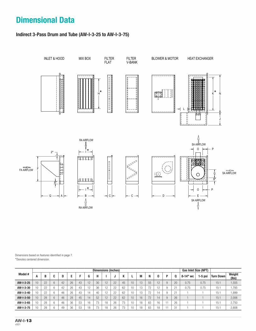
Model #Dimensions (inches) Gas Inlet Size (NPT)
A B C D E F G H I J K L M N O P Q 8-14" wc 1-5 psi Turn Down Weight (lbs)
AW-I-3-25 10 22 6 42 26 43 12 30 12 22 45 10 13 55 12 9 20 0.75 0.75 15:1 1,555
AW-I-3-30 10 22 6 42 26 43 12 36 12 22 62 10 13 72 12 9 21 0.75 0.75 15:1 1,785
AW-I-3-40 10 22 6 46 26 43 14 40 12 22 62 10 13 72 14 9 21 1 1 15:1 1,899
AW-I-3-50 10 28 6 46 28 45 14 52 12 22 62 10 16 72 14 9 26 1 1 15:1 2,006
AW-I-3-65 10 28 6 46 36 53 16 73 18 26 73 10 18 83 16 11 26 1 1 15:1 2,750
AW-I-3-75 10 28 6 49 36 53 18 73 18 26 73 10 18 83 18 11 31 1 1 15:1 2,808
Dimensions based on features identified in page 7.*Denotes centered dimension.
Dimensional Data
Indirect 3-Pass Drum and Tube (AW-I-3-25 to AW-I-3-75)
F
B
I
I
C C D E
G
O
O
A Q
P
2"
8"
P
6"
FA AIRFLOW
RA AIRFLOW
RA AIRFLOW
SA AIRFLOW
SA AIRFLOW
SA AIRFLOW
AW-I-4 25-75
H
J
K N
L
INLET & HOOD MIX BOX FILTERFLAT
FILTERV-BANK
BLOWER & MOTOR HEAT EXCHANGER
*
**
*

AW-I-14For more information visit www.priceindustries.comv001
Model #Dimensions (inches) Gas Inlet Size (NPT)
A B C D E F G H I J K L M N O P Q R 8-14" wc 1-5 psi Turn Down Weight (lbs)
AW-I-3-85 10 34 6 49 63 44 25 71 18 26 81 12 20 91 20 5 33 30 1.25 1 15:1 3,254
AW-I-3-100 10 34 32 57 63 44 28 71 18 26 81 12 20 91 20 5 35 30 1.25 1 15:1 3,894
AW-I-3-125 10 34 6 57 86 58 32 72 24 28 82 12 22 92 20 5 24 30 1.25 1 15:1 4,692
AW-I-3-150 10 40 30 59 86 58 32 72 24 28 82 12 22 92 20 5 27 30 1.5 1.25 15:1 5,137
AW-I-3-175 10 40 30 59 86 58 32 94 24 28 104 12 24 114 24 5 26 34 2 1.5 15:1 5,988
AW-I-3-200 10 40 30 66 86 58 32 94 24 28 104 12 24 114 24 5 30 34 2 1.5 15:1 6,354
AW-I-3-250 10 40 32 70 99 66 32 121 30 33 131 12 26 141 30 5 30 40 2.5 2 15:1 8,183
AW-I-3-300 10 52 32 74 99 66 32 121 30 33 131 12 26 141 30 5 37 40 2.5 2 15:1 8,374
AW-I-3-400 10 58 32 79 135 81 46 136 30 33 146 12 28 156 36 5 40 46 2.5 2 15:1 10,775
Dimensions based on features identified in page 8.*Denotes centered dimension.
Dimensional Data
Indirect 3-Pass Drum and Tube (AW-I-3-85 to AW-I-3-400)
F
A B I
I
C C D E Q O
O
G
Q P
6"
2" P
RA AIRFLOW
RA AIRFLOW
FA AIRFLOW
SA AIRFLOW
SA AIRFLOW
SA AIRFLOW
4" STRUCTURAL ONAW-I-3-175 AND LARGER
H
J
K K
M
L
N
INLET & HOOD MIX BOX FILTERFLAT
FILTERV-BANK
BLOWER & MOTOR HEAT EXCHANGER DISCHARGEPLENUM
AW-I-3 85-400
*
* *
*
*
*
R

AW-I-15v001
Model #Dimensions (inches) Gas Inlet Size (NPT)
A B C D E F G H I J K L N O P Q 8-14" wc 1-5 psi Turn Down Weight (lbs)
AW-I-4-25 10 22 6 41 37 49 18 24 12 22 20 12 34 18 9.5 27 0.75 0.75 15:1 1,429
AW-I-4-35 10 22 6 45 37 49 18 40 12 22 34 12 50 18 9.5 25 1 1 15:1 1,756
AW-I-4-40 10 22 6 45 37 49 18 40 12 22 34 12 50 18 9.5 28 1 1 15:1 1,808
AW-I-4-50 10 28 6 48 42 55 18 50 12 22 44 12 60 18 12 28 1 1 15:1 2,209
AW-I-4-55 10 28 6 48 42 55 18 50 12 22 44 12 60 18 12 33 1 1 15:1 2,209
AW-I-4-65 10 28 6 45 42 55 20 70 18 26 64 12 80 20 11 29 1 1 15:1 2,764
AW-I-4-75 10 28 6 48 42 55 20 70 18 26 64 12 80 20 11 34 1 1 15:1 2,860
Dimensions based on features identified in page 9.*Denotes centered dimension.
Dimensional Data
Indirect 4-Pass Drum and Tube (AW-I-4-25 to AW-I-4-75)
F
B
I
I
C C D E
G
O
O
A Q
P
2"
8"
P
6"
FA AIRFLOW
RA AIRFLOW
RA AIRFLOW
SA AIRFLOW
SA AIRFLOW
SA AIRFLOW
AW-I-4 25-75
H
J
K N
L
INLET & HOOD MIX BOX FILTERFLAT
FILTERV-BANK
BLOWER & MOTOR HEAT EXCHANGER
*
**
*

AW-I-16For more information visit www.priceindustries.comv001
Model #Dimensions (inches) Gas Inlet Size (NPT)
A B C D E F G H I J K L N O P Q 8-14" wc 1-5 psi Turn Down Weight (lbs)
AW-I-4-85 10 34 6 49 65 50 18 62 18 30 70 12 82 20 5 39 1.25 1 15:1 3,464
AW-I-4-100 10 34 6 57 65 50 18 62 18 30 70 12 82 20 5 42 1.25 1 15:1 3,769
AW-I-4-125 10 34 6 57 79 54 24 82 24 32 90 12 102 30 5 24 1.25 1 15:1 4,650
AW-I-4-150 10 40 30 59 79 54 24 82 24 32 90 12 102 30 5 27 1.5 1.25 15:1 5,234
AW-I-4-175 10 40 30 59 79 54 24 82 24 32 90 12 102 30 5 31 2 1.5 15:1 5,395
AW-I-4-200 10 40 30 66 79 58 30 102 24 36 110 12 122 32 5 29 2 1.5 15:1 6,496
AW-I-4-225 10 40 32 70 79 58 30 102 24 36 110 12 122 32 5 32 2 1.5 15:1 6,837
AW-I-4-250 10 40 32 70 79 58 30 102 24 36 110 12 122 32 5 37 2.5 2 15:1 6,908
AW-I-4-275 10 52 32 74 87 64 30 118 24 36 126 12 138 32 5 32 2.5 2 15:1 8,717
AW-I-4-300 10 52 6 74 104 70 30 142 30 36 150 12 162 32 5 32 2.5 2 15:1 9,652
AW-I-4-350 10 58 32 74 104 70 30 142 30 36 150 12 162 32 5 37 2.5 2 15:1 10,281
AW-I-4-400 10 58 32 79 104 70 30 142 30 36 150 12 162 32 5 40 2.5 2 15:1 10,735
AW-I-4-500 10 64 32 91 143 82 48 162 36 36 170 12 182 32 5 46 N/A 2.5 15:1 15,129
AW-I-4-600 10 64 32 100 143 82 48 162 36 36 170 12 182 32 5 54 N/A 2.5 15:1 15,647
Dimensions based on features identified in pages 10 and 11.*Denotes centered dimension.
Dimensional Data
Indirect 4-Pass Drum and Tube (AW-I-4-85 to AW-I-4-600)
F
A B I
I
C C D E
G
O P
O P
Q
2"
6"
RA AIRFLOW
RA AIRFLOW
FA AIRFLOW SA AIRFLOW
SA AIRFLOW
SA AIRFLOW
AW-I-4 85-600
4" STRUCTURAL ONAW-I-4-175 AND LARGER
H
J
K
L
N
INLET & HOOD MIX BOX FILTERFLAT
FILTERV-BANK
BLOWER & MOTOR HEAT EXCHANGER
*
*
*
* *

AW-I-17v001
Typical Unit Clearances for AW-I-4 Units
ACCESS SIDE 30” (75 cm)
FLUE9” (22 cm)
FLUE LOCATION
NO ACCESS SIDES6” (15 cm) minimum24” (60 cm) recommended
CONTROL CABINET36” (1 m) minimum48” (1.3 m) recommended
TOP6” (15 cm) minimum
NO ACCESS BACK20” (50 cm) minimum24” (60 cm) recommended
ACCESS SIDE 30” (75 cm)
FLUE9” (22 cm)
FLUE LOCATION
NO ACCESS SIDES6” (15 cm) minimum24” (60 cm) recommended
CONTROL CABINET36” (1 m) minimum48” (1.3 m) recommended
TOP6” (15 cm) minimum
NO ACCESS BACK20” (50 cm) minimum24” (60 cm) recommended
ACCESS SIDE 30” (75 cm)
FLUE9” (22 cm)
FLUE LOCATION
NO ACCESS SIDES6” (15 cm) minimum24” (60 cm) recommended
CONTROL CABINET36” (1 m) minimum48” (1.3 m) recommended
TOP6” (15 cm) minimum
NO ACCESS BACK20” (50 cm) minimum24” (60 cm) recommended
ACCESS SIDE 30” (75 cm)
NO ACCESS SIDES6” (15 cm) minimum24” (60 cm) recommended
CONTROL CABINET36” (1 m) minimum48” (1.3 m) recommended
FLUE LOCATION
Clearance Data
Typical Unit Clearances for AW-I-3 Units

AW-I-18For more information visit www.priceindustries.comv001
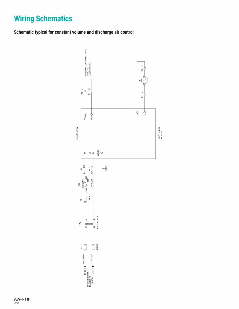
Wiring Schematics
Schematic typical for constant volume and discharge air control
AW-I-19v001
Wiring Schematics
Schematic typical for constant volume and discharge air control

AW-I-20For more information visit www.priceindustries.comv001
Wiring Schematics
Schematic typical for constant volume and discharge air control

AW-I-21v001
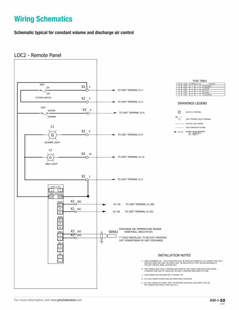
Wiring Schematics
Schematic typical for constant volume and discharge air control
AW-I-22For more information visit www.priceindustries.comv001
Wiring Schematics
Schematic typical for constant volume and discharge air control

Product Improvement is a continuing endeavour at Price. Therefore, specifications are subject to change without notice.Consult your Price Sales Representative for current specifications or more detailed information. Not all products may be
available in all geographic areas. All goods described in this document are warranted as described in the Limited Warrantyshown at priceindustries.com. The complete Price product catalog can be viewed online at priceindustries.com.
® Price is a registered trademark of Price Industries Limited. © 2016. Printed in Canada 2016. v001 | MI0010440