AVT Bigeye G - Daheng Imagegb.daheng-image.com/cn/products/avt/manual/AVT_Bigeye-G_TechMa… ·...
58
Technical Manual AVT Cooled CCD Cameras V2.1.0 2013-July-08 Allied Vision Technologies GmbH Taschenweg 2a D-07646 Stadtroda / Germany AVT Bigeye G
Transcript of AVT Bigeye G - Daheng Imagegb.daheng-image.com/cn/products/avt/manual/AVT_Bigeye-G_TechMa… ·...

Technical ManualAVT Cooled CCD Cameras
V2.1.0
2013-July-08
Allied Vision Technologies GmbHTaschenweg 2aD-07646 Stadtroda / Germany
AVT Bigeye G

Bigeye G Technical Manual V2.1.0
2
Legal noticeTrademarksUnless stated otherwise, all trademarks appearing in this document of Allied Vision Technologies are brands protected by law.
WarrantyThe information provided by Allied Vision Technologies is supplied without any guarantees or warranty whatsoever, be it specific or implicit. Also excluded are all implicit warranties concern-ing the negotiability, the suitability for specific applications or the non-breaking of laws and pat-ents. Even if we assume that the information supplied to us is accurate, errors and inaccuracy may still occur.
CopyrightAll texts, pictures and graphics are protected by copyright and other laws protecting intellectual property. It is not permitted to copy or modify them for trade use or transfer, nor may they be used on web sites.
Allied Vision Technologies GmbH 08/2013All rights reserved.Managing Director: Mr. Frank GrubeTax ID: DE 184383113
Headquarters:
Taschenweg 2aD-07646 Stadtroda, GermanyTel: +49 (0)36428 6770Fax: +49 (0)36428 677-28e-mail: [email protected]
Bigeye G Technical Manual V2.1.0
3
Contents
Contacting Allied Vision Technologies ................................................... 5
Introduction ............................................................................................................ 7
Document history............................................................................................................ 7Manual overview ............................................................................................................. 8Conventions used in this manual ........................................................................................ 9
Styles ....................................................................................................................... 9Symbols.................................................................................................................... 9
More information .......................................................................................................... 10Before operation........................................................................................................... 10Safety warnings ............................................................................................................ 11
Bigeye G GigE cameras ..................................................................................12
Conformity ..............................................................................................................14CE .......................................................................................................................... 14
Specifications .......................................................................................................15
Bigeye G-132B Cool / Bigeye G-132B NIR Cool .................................................................... 15Bigeye G-283B Cool ....................................................................................................... 19Bigeye G-629B Cool / Bigeye G-629B NIR Cool .................................................................... 23Bigeye G-1100B Cool ..................................................................................................... 27Spectral sensitivity ........................................................................................................ 31
Filters and lenses ...............................................................................................35
Filters ........................................................................................................................ 35Camera lenses .............................................................................................................. 35
Camera dimensions ..........................................................................................38
Bigeye G-132B Cool / Bigeye G-283B Cool .......................................................................... 38Bigeye G-629B Cool ....................................................................................................... 39Bigeye G-1100B Cool ..................................................................................................... 40
Camera interfaces .............................................................................................41
Gigabit Ethernet port ..................................................................................................... 41Camera I/O connector pin assignment ............................................................................... 42Control signals ............................................................................................................. 43
Inputs .................................................................................................................... 43Input/output pin control............................................................................................ 44Outputs .................................................................................................................. 44Trigger timing diagram .............................................................................................. 45Notes on triggering ................................................................................................... 46

Bigeye G Technical Manual V2.1.0
4
Description of the data path........................................................................48
Block diagrams of the cameras......................................................................................... 48Monochrome cameras ................................................................................................ 48
Available Bigeye G camera controls................................................................................... 49Frame memory.............................................................................................................. 56
Index...........................................................................................................................57

Contacting Allied Vision Technologies
Bigeye G Technical Manual V2.1.0
5
Contacting Allied Vision Technologies
Info
Technical information:http://www.alliedvisiontec.com
Support:[email protected]
Allied Vision Technologies GmbH (Headquarters)Taschenweg 2a07646 Stadtroda, GermanyTel: +49 36428-677-0Fax.: +49 36428-677-28e-mail: [email protected]
Allied Vision Technologies Canada Inc.101-3750 North Fraser WayBurnaby, BC, V5J 5E9, CanadaTel: +1 604-875-8855Fax: +1 604-875-8856e-mail: [email protected]
Allied Vision Technologies Inc.38 Washington StreetNewburyport, MA 01950, USAToll Free number +1 877-USA-1394Tel: +1 978-225-2030Fax: +1 978-225-2029e-mail: [email protected]
Allied Vision Technologies Asia Pte. Ltd.82 Playfair Road#07-02 D’LithiumSingapore 368001Tel: +65 6634-9027Fax: +65 6634-9029e-mail: [email protected]
Allied Vision Technologies (Shanghai) Co., Ltd.2-2109 Hongwell International Plaza1602# ZhongShanXi RoadShanghai 200235, ChinaTel: +86 (21) 64861133Fax: +86 (21) 54233670e-mail: [email protected]

Contacting Allied Vision Technologies
Bigeye G Technical Manual V2.1.0
6

Introduction
Bigeye G Technical Manual V2.1.0
7
Introduction
This Bigeye G Technical Manual describes in depth the technical specifications, dimensions, all pixel formats, bandwidth and frame rate related subjects.
For information on hardware installation, safety warnings, pin assignments on I/O connectors and GigE port connectors read the AVT GigE Installation Man-ual.
For information on camera features (camera controls) read the AVT GigE camera and driver attributes document.
Document history
Note
Please read through this manual carefully.
We assume that you have read already the AVT GigE Installation Manual and that you have installed the required hardware and software on your PC or laptop (Gigabit Ethernet network card, cables).
http://www.alliedvisiontec.com/emea/support/downloads/product-literature/hardware-installation-guide.html
Version Date Remarks
V2.0.0 14.09.12 New Manual - COMMERCIAL RELEASE status
V2.1.0 08-July-2013 • Updated RoHS (2002/95/EC) to RoHS (2011/65/EU)• Updated Specifications -> Power requirements (inrush
current)• Added „Surge“ warning• Corrected number of cycles of Bigeye G-629B Cool / Bigeye
G-629B NIR Cool shutter• Corrections derived from terminology alignment
Table 1: Document history

Introduction
Bigeye G Technical Manual V2.1.0
8
Manual overview
This manual overview outlines the contents of each chapter of this manual.• Chapter Contacting Allied Vision Technologies on page 5 lists AVT contact
data (phone numbers and URLs) for both:– Technical information / ordering– Commercial information
• Chapter Introduction on page 7 (this chapter) gives you the document history, a manual overview (short description of each chapter) and conventions used in this manual (styles and symbols). Furthermore, you learn how to get more information on AVT GigE Installation Manual, available AVT software (incl. documentation) and where to get it.
• Chapter Bigeye G GigE cameras on page 12 gives you a short introduction to the Bigeye G cameras with their GigE technology. Links are provided to information on GigE Vision and GenICam and to data sheets and brochures on AVT website.
• Chapter Conformity on page 14 gives you information about conformity of AVT cameras (CE, RoHS).
• Chapter Filters and lenses on page 35 describes the available filters. Suitable camera lenses for different focal lengths are provided for different camera models.
• Chapter Specifications on page 15 lists camera details and measured spectral sensitivity diagrams for each camera type.
• Chapter Camera dimensions on page 38 provides CAD drawings of standard housing models.
• Chapter Camera interfaces on page 41 describes in general the inputs/outputs of the cameras (incl. trigger features): Gigabit Ethernet port, camera I/O connector pin assignment, schematic input/output block diagrams as well as a general description of trigger (timing diagram, definitions and rules).
• Chapter Description of the data path on page 48 describes the data path of the Bigeye G cameras in block diagrams as well as available Bigeye G camera controls. For a detailed description of all camera controls see the document: AVT GigE camera and driver attributes. Furthermore the image memory, color interpolation is described.
• Chapter Index on page 57 gives you quick access to all relevant data in this manual.
Introduction
Bigeye G Technical Manual V2.1.0
9
Conventions used in this manual
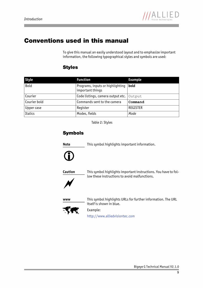
To give this manual an easily understood layout and to emphasize important information, the following typographical styles and symbols are used:
Styles
Symbols
Style Function Example
Bold Programs, inputs or highlighting important things
bold
Courier Code listings, camera output etc. Output
Courier bold Commands sent to the camera Command
Upper case Register REGISTER
Italics Modes, fields Mode
Table 2: Styles
Note
This symbol highlights important information.
Caution
This symbol highlights important instructions. You have to fol-low these instructions to avoid malfunctions.
www
This symbol highlights URLs for further information. The URL itself is shown in blue.
Example:
http://www.alliedvisiontec.com

Introduction
Bigeye G Technical Manual V2.1.0
10
More information
For more information on hardware and software read the following:• AVT GigE installation manual describes the hardware installation proce-
dures for the AVT GigE cameras (Manta/Bigeye G). Additionally you get safety instructions and information about camera interfaces (GigE port,I/O connector, inputs and outputs).
• AVT GigE camera and driver attributes describes the available camera controls when using AVT‘s PvAPI GigE SDK.
Before operation
Target group This Technical Manual is the guide to detailed technical information of the camera and is written for experts.
Getting started For a quick guide how to get started read AVT GigE installation manual first.
www
For downloading the AVT GigE installation manual and AVT GigE camera and driver attributes go to:
http://www.alliedvisiontec.com/emea/support/downloads/product-literature.html
www
All software packages (including documentation and release notes) provided by AVT can be downloaded at:
http://www.alliedvisiontec.com/emea/products/software.html
Note
Please read through this manual carefully before operating the camera.
For information on AVT accessories and AVT software read AVT GigE installation manual.
Caution
Before operating any AVT camera read safety instructions and ESD warnings in AVT GigE installation manual.

Introduction
Bigeye G Technical Manual V2.1.0
11
Safety warnings
Caution
Electrostatic discharge
The camera contains sensitive electronic components that can be destroyed by electrostatic discharge.
Use sufficient grounding to minimize the risk of damage.

Bigeye G GigE cameras
Bigeye G Technical Manual V2.1.0
12
Bigeye G GigE cameras
Bigeye G The Bigeye G cameras are cooled cameras equipped with high-quality CCD sensors from SONY (with EXview HAD microlenses) or from Truesense (former KODAK) both providing a high quantum efficiency.
For each of these sensors AVT applies special measures (by using only high-quality components and designing a sophisticated circuitry) to provide an outstanding image quality with low noise.
Image applications The Bigeye G camera series is equipped with a GigE Vision compliant AVT GigE module. This series distinguishes from the Bigeye P series (equipped with Pleora GigE module) by providing an extended feature set and AVT software support.
GigE GigE is the abbreviation for Gigabit Ethernet.
All AVT Bigeye G cameras are GigE Vision compliant cameras with a Gigabit Ethernet interface. AVT Bigeye G cameras work with standard Gigabit Ethernet hardware and cables. AVT Bigeye G cameras support cable lengths up to 100 m, using conventional Cat5e or better network cables.
Gigabit Ethernet has a data rate of 1000 Mbit/s or 1 Gbit/s. Gigabit Ethernet is capable of handling streaming image data and providing reliable transmission of image data.
GigE Vision The GigE Vision standard is an interface standard for high-performance machine vision cameras that is widely supported in the industrial imaging industry. GigE (Gigabit Ethernet), however, is simply the network structure GigE Vision is built on.
The GigE Vision standard includes both a hardware interface standard (Gigabit Ethernet) and standardized communication with the camera and controlling the camera.
GenICam The GigE Vision camera control registers are based on a command structure called GenICam that is administered through the European Machine Vision Association (EMVA). GenICam seeks to establish a common camera control interface: third-party software can communicate with cameras from various manufacturers without customization. GenICam is incorporated as part of the GigE Vision standard, so any GigE Vision compliant camera also complies with GenICam.
Key benefits • Low-noise CCD cameras with stabilized dual-level Peltier cooling• Excellent signal-to-noise ratio• Low dark noise• Excellent quantum efficiency and low readout noise contribute to the
cameras‘ outstanding performance for low-light applications up to very long exposure times (> 60 minutes)
• 4 user-configurable input and output ports (no additional I/O cards needed)
Bigeye G GigE cameras
Bigeye G Technical Manual V2.1.0
13
• Robust metal housing• GigE Vision compliant interface enables support for any GigE Vision
compliant third-party software solution• NIR-optimized variants available
(currently only Bigeye G-132 and Bigeye G-629)
www
For further information on the highlights of Bigeye G types, the Bigeye G family and the whole range of AVT GigE cameras read the data sheets and brochures on the website of Allied Vision Technologies:
http://www.alliedvisiontec.com/emea/products/cameras.html
Conformity
Bigeye G Technical Manual V2.1.0
14
ConformityAllied Vision Technologies declares under its sole responsibility that all stan-dard cameras of the AVT Bigeye G family that this declaration relates to, are in conformity with the following standards or other normative documents:• CE, following the provisions of 2004/108/EG directive• RoHS (2011/65/EU)
CEWe declare, under our sole responsibility, that the previously described AVT Bigeye G cameras conform to the directives of CE.

Specifications
Bigeye G Technical Manual V2.1.0
15
Specifications
Bigeye G-132B Cool / Bigeye G-132B NIR Cool
Note
The warranty becomes void in case of unauthorized tampering or any modifications not approved by the manufacturer.
Caution
Surge
To avoid damage caused by surge, connect the camera to an AC/DC power supply. Use a certified industrial power supply that complies with common industrial standards. Make sure the polarization of the power supply is correct.
During the camera start-up, inrush currents ≥4 A can occur for 20 ms. Use a sufficiently dimensioned power supply to avoid damage to the camera.
For the DC signal, use cable lengths less than 30 m. Consider that the voltage drop increases with the cable length.
AVT (or your local dealer) provides suitable power supplies:
http://www.alliedvisiontec.com/emea/products/accessories.html

Specifications
Bigeye G Technical Manual V2.1.0
16
Feature Specification
Sens
or a
nd le
ns m
ount
Sensor SONY ICX285AL with EXview HAD CCD microlenses
Max. resolution (HxV) 1280 x 1024 pixels
Sensor type CCD progressive
Sensor size Type 2/3
Sensor diagonal 11 mm
Effective chip size 8.26 mm x 6.6 mm
Cell size 6.45 μm x 6.45 μm
Lens mount C-Mount: 17.526 mm (in air); Ø 24.5 mm (32 tpi)maximum protrusion: 7.5 mm
Shutter type Electronic global shutter
Max. frame rateat full resolution
12.5 fps (continuous)6.25 fps (IOD)
Max. frame rate with binningat 640 x 512
25 fps (continuous)12.5 fps (IOD)
ADC 12 bits
Outp
ut Bit depth 12 bits
Pixel format Mono8, Mono12, Mono12Packed
Table 3: Specification Bigeye G-132B Cool / Bigeye G-132B NIR Cool
Note
Maximum protrusion means the distance from lens flange to the glass filter in the camera.
Note
IOD mode uses different exposure process for optimizing image quality. In combination with SONY ICX285 this leads to the big differences in frame rates for continuous and IOD mode.

Specifications
Bigeye G Technical Manual V2.1.0
17
Feat
ures
Exposure time 80077 μs … 4294.97 s in 1 μs increments
Binning 2x1, 2x2
Gain 0, +6 dB
Gamma 0.45, 0.5, 0.7
ROI available (Note: decreasing ROI does not increase frame rate)
Trigger modes Continuous mode (image acquisition with maximum frame rate)IOD mode (Image on Demand: triggered image acquisition)
External trigger event Rising edge, falling edge, any edge, level high, level low
External trigger delay 0 to 102.26 seconds in 1 μs increments2x2 binning mode: 0 to 204.522 seconds in 1 μs increments
Fixed rate control 0.000233 fps to max. frame rate
Imaging modes Free-running, external trigger, fixed rate, software trigger
Sync Out modes Trigger ready, trigger input, exposing, readout, imaging, strobe, GPO, CCDTemperatureOK
Internal image memory 32 MByte, up to 25 frames
Inte
rfac
es
Digital interface IEEE 802.3 1000BASE-T (GigE Vision V1.2 compliant)
GigE connector RJ45 (8P8C) with horizontal screw-locks
I/O port connector 20-pin Mini D Ribbon (MDR) shielded I/O connector with screw-locks
Camera control interface GenICam V1.0 compliant
I/O 4 inputs (3 optocoupled)4 outputs (3 optocoupled)
Oper
atin
g co
ndit
ions
Operating temperature 0 °C to +35 °C ambient temperature (without condensation)
Stabilized cooling temperature
-20 °C (Peltier cooling)(up to +25 °C ambient temperature)
Power requirements +12 V (+5 %), max. 3.0 A (during camera start-up: inrush current ≥4 A for 20 ms, capacitive load < 2000 μF)
Power consumption Max. 36 wattsTypical 18 watts (@ 12 V DC)(maximal frame rates at full resolution)
Feature Specification
Table 3: Specification Bigeye G-132B Cool / Bigeye G-132B NIR Cool
Note
The number of frames (StreamHoldCapacity) depends on resolution and pixel format. Listed number of frames is typical for full resolution and Mono8.

Specifications
Bigeye G Technical Manual V2.1.0
18
Mec
hani
cs Mass (without lens) <1270 g
Dimensions (L x W x H) 100.8 mm x 90 mm x 99 mm; incl. connectors, without tripod and lens
Regulations CE, RoHS (2011/65/EU)
Opti
ons
Optional NIR variant Bigeye G-132B NIR Cool
Software packages AVT VIMBA SDKAVT PvAPI SDKAcquireControl software (V4.0.0 or greater)
Feature Specification
Table 3: Specification Bigeye G-132B Cool / Bigeye G-132B NIR Cool

Specifications
Bigeye G Technical Manual V2.1.0
19
Bigeye G-283B Cool
Note
The warranty becomes void in case of unauthorized tampering or any modifications not approved by the manufacturer.
Caution
Surge
To avoid damage caused by surge, connect the camera to an AC/DC power supply. Use a certified industrial power supply that complies with common industrial standards. Make sure the polarization of the power supply is correct.
During the camera start-up, inrush currents ≥4 A can occur for 20 ms. Use a sufficiently dimensioned power supply to avoid damage to the camera.
For the DC signal, use cable lengths less than 30 m. Consider that the voltage drop increases with the cable length.
AVT (or your local dealer) provides suitable power supplies:
http://www.alliedvisiontec.com/emea/products/accessories.html

Specifications
Bigeye G Technical Manual V2.1.0
20
Feature Specification
Sens
or a
nd le
ns m
ount
Sensor SONY ICX674ALG with EXview HAD CCD II microlenses
Max. resolution (HxV) 1928 x 1452 pixels
Sensor type CCD progressive
Sensor size Type 2/3
Sensor diagonal 10.972 mm
Effective chip size 10.7 mm x 9.2 mm
Cell size 4.54 μm x 4.54 μm
Lens mount C-Mount: 17.526 mm (in air); Ø 24.5 mm (32 tpi)maximum protrusion: 7.5 mm
Shutter type Electronic global shutter
Max. frame rateat full resolution
6.0 fps (continuous)5.7 fps (IOD)
Max. frame rate with binningat 964 x762
12 fps (continuous)10.9 fps (IOD)
ADC 14 bits
Outp
ut Bit depth 14 bits
Pixel format Mono8, Mono12Packed, Mono14
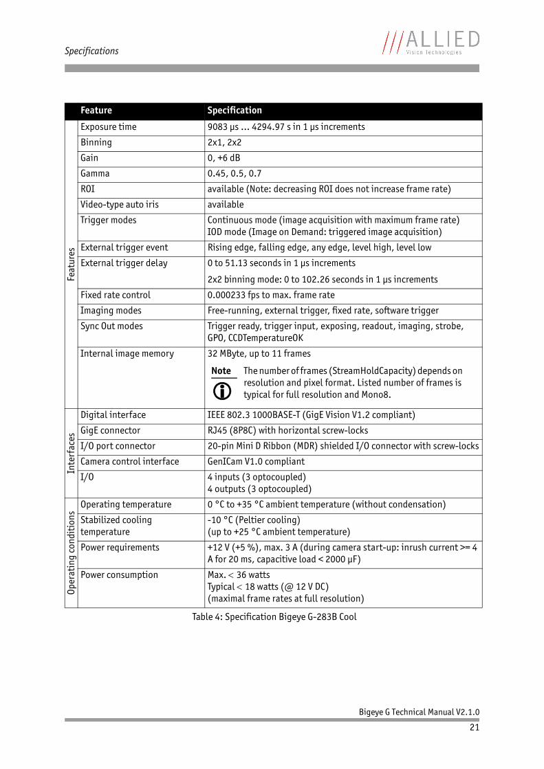
Table 4: Specification Bigeye G-283B Cool
Note
Maximum protrusion means the distance from lens flange to the glass filter in the camera.
Specifications
Bigeye G Technical Manual V2.1.0
21
Feat
ures
Exposure time 9083 μs … 4294.97 s in 1 μs increments
Binning 2x1, 2x2
Gain 0, +6 dB
Gamma 0.45, 0.5, 0.7
ROI available (Note: decreasing ROI does not increase frame rate)
Video-type auto iris available
Trigger modes Continuous mode (image acquisition with maximum frame rate)IOD mode (Image on Demand: triggered image acquisition)
External trigger event Rising edge, falling edge, any edge, level high, level low
External trigger delay 0 to 51.13 seconds in 1 μs increments
2x2 binning mode: 0 to 102.26 seconds in 1 μs increments
Fixed rate control 0.000233 fps to max. frame rate
Imaging modes Free-running, external trigger, fixed rate, software trigger
Sync Out modes Trigger ready, trigger input, exposing, readout, imaging, strobe, GPO, CCDTemperatureOK
Internal image memory 32 MByte, up to 11 frames
Inte
rfac
es
Digital interface IEEE 802.3 1000BASE-T (GigE Vision V1.2 compliant)
GigE connector RJ45 (8P8C) with horizontal screw-locks
I/O port connector 20-pin Mini D Ribbon (MDR) shielded I/O connector with screw-locks
Camera control interface GenICam V1.0 compliant
I/O 4 inputs (3 optocoupled)4 outputs (3 optocoupled)
Oper
atin
g co
ndit
ions
Operating temperature 0 °C to +35 °C ambient temperature (without condensation)
Stabilized cooling temperature
-10 °C (Peltier cooling)(up to +25 °C ambient temperature)
Power requirements +12 V (+5 %), max. 3 A (during camera start-up: inrush current >= 4 A for 20 ms, capacitive load < 2000 μF)
Power consumption Max. 36 wattsTypical 18 watts (@ 12 V DC)(maximal frame rates at full resolution)
Feature Specification
Table 4: Specification Bigeye G-283B Cool
Note
The number of frames (StreamHoldCapacity) depends on resolution and pixel format. Listed number of frames is typical for full resolution and Mono8.

Specifications
Bigeye G Technical Manual V2.1.0
22
Mec
hani
cs Mass (without lens) < 1250 g
Dimensions (L x W x H) 100.8 mm x 90 mm x 99 mm; incl. connectors, without tripod and lens
Regulations CE, RoHS (2011/65/EU)
Opti
ons Software packages AVT VIMBA SDK
AVT PvAPI SDKAcquireControl software (V4.0.0 or greater)
Feature Specification
Table 4: Specification Bigeye G-283B Cool

Specifications
Bigeye G Technical Manual V2.1.0
23
Bigeye G-629B Cool / Bigeye G-629B NIR Cool
Note
The warranty becomes void in case of unauthorized tampering or any modifications not approved by the manufacturer.
Caution
Surge
To avoid damage caused by surge, connect the camera to an AC/DC power supply. Use a certified industrial power supply that complies with common industrial standards. Make sure the polarization of the power supply is correct.
During the camera start-up, inrush currents ≥4 A can occur for 20 ms. Use a sufficiently dimensioned power supply to avoid damage to the camera.
For the DC signal, use cable lengths less than 30 m. Consider that the voltage drop increases with the cable length.
AVT (or your local dealer) provides suitable power supplies:
http://www.alliedvisiontec.com/emea/products/accessories.html

Specifications
Bigeye G Technical Manual V2.1.0
24
Feature Specification
Sens
or a
nd le
ns m
ount
Sensor Truesense KAF6303E
Max. resolution (HxV) 3072 x 2048 pixels
Sensor type Full-frame CCD
Sensor size Type 35 mm
Sensor diagonal 33.229 mm
Effective chip size 27.65 mm x 18.43 mm
Cell size 9.00 μm x 9.00 μm
Lens mount F-Mount: 46.5 mm (in air)maximum protrusion: 26 mm
Shutter type Built-in electromechanical full-frame shutter (min. 100,000 cycles)
Max. frame rateat full resolution
0.67 fps (IOD)
Max. frame rate with binningat 1536x1024
1.9 fps (IOD)
ADC 14 bits
Outp
ut Bit depth 14 bits
Pixel format Mono8, Mono12, Mono12Packed, Mono14
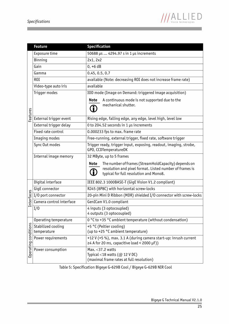
Table 5: Specification Bigeye G-629B Cool / Bigeye G-629B NIR Cool
Note
Maximum protrusion means the distance from lens flange to the glass filter in the camera.
Specifications
Bigeye G Technical Manual V2.1.0
25
Feat
ures
Exposure time 50688 μs … 4294.97 s in 1 μs increments
Binning 2x1, 2x2
Gain 0, +6 dB
Gamma 0.45, 0.5, 0.7
ROI available (Note: decreasing ROI does not increase frame rate)
Video-type auto iris available
Trigger modes IOD mode (Image on Demand: triggered image acquisition)
External trigger event Rising edge, falling edge, any edge, level high, level low
External trigger delay 0 to 204.52 seconds in 1 μs increments
Fixed rate control 0.000233 fps to max. frame rate
Imaging modes Free-running, external trigger, fixed rate, software trigger
Sync Out modes Trigger ready, trigger input, exposing, readout, imaging, strobe, GPO, CCDTemperatureOK
Internal image memory 32 MByte, up to 5 frames
Inte
rfac
es
Digital interface IEEE 802.3 1000BASE-T (GigE Vision V1.2 compliant)
GigE connector RJ45 (8P8C) with horizontal screw-locks
I/O port connector 20-pin Mini D Ribbon (MDR) shielded I/O connector with screw-locks
Camera control interface GenICam V1.0 compliant
I/O 4 inputs (3 optocoupled)4 outputs (3 optocoupled)
Oper
atin
g co
ndit
ions
Operating temperature 0 °C to +35 °C ambient temperature (without condensation)
Stabilized cooling temperature
+5 °C (Peltier cooling)(up to +25 °C ambient temperature)
Power requirements +12 V (+5 %), max. 3.1 A (during camera start-up: inrush current ≥4 A for 20 ms, capacitive load < 2000 μF))
Power consumption Max. 37.2 wattsTypical 18 watts (@ 12 V DC)(maximal frame rates at full resolution)
Feature Specification
Table 5: Specification Bigeye G-629B Cool / Bigeye G-629B NIR Cool
Note
A continuous mode is not supported due to the mechanical shutter.
Note
The number of frames (StreamHoldCapacity) depends on resolution and pixel format. Listed number of frames is typical for full resolution and Mono8.
Specifications
Bigeye G Technical Manual V2.1.0
26
Mec
hani
cs
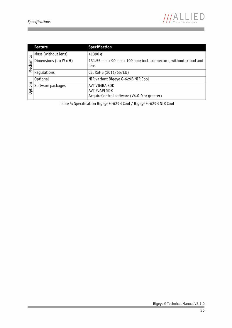
Mass (without lens) <1390 g
Dimensions (L x W x H) 131.55 mm x 90 mm x 109 mm; incl. connectors, without tripod and lens
Regulations CE, RoHS (2011/65/EU)
Opti
ons
Optional NIR variant Bigeye G-629B NIR Cool
Software packages AVT VIMBA SDKAVT PvAPI SDKAcquireControl software (V4.0.0 or greater)
Feature Specification
Table 5: Specification Bigeye G-629B Cool / Bigeye G-629B NIR Cool
Specifications
Bigeye G Technical Manual V2.1.0
27
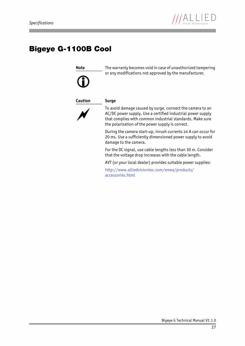
Bigeye G-1100B Cool
Note
The warranty becomes void in case of unauthorized tampering or any modifications not approved by the manufacturer.
Caution
Surge
To avoid damage caused by surge, connect the camera to an AC/DC power supply. Use a certified industrial power supply that complies with common industrial standards. Make sure the polarization of the power supply is correct.
During the camera start-up, inrush currents ≥4 A can occur for 20 ms. Use a sufficiently dimensioned power supply to avoid damage to the camera.
For the DC signal, use cable lengths less than 30 m. Consider that the voltage drop increases with the cable length.
AVT (or your local dealer) provides suitable power supplies:
http://www.alliedvisiontec.com/emea/products/accessories.html

Specifications
Bigeye G Technical Manual V2.1.0
28
Feature Specification
Sens
or a
nd le
ns m
ount
Sensor Truesense KAI11002
Max. resolution (HxV) 4024 x 2680 pixels
Sensor type CCD progressive
Sensor size Type 35 mm
Sensor diagonal 43.5 mm
Effective chip size 36.22 mm x 24.12 mm
Cell size 9.00 μm x 9.00 μm
Lens mount F-Mount: 46.5 mm (in air)maximum protrusion: 30 mm
Shutter type Electronic global shutter
Max. frame rateat full resolution
1.58 fps (continuous)1.58 fps (IOD)
Max. frame rate with binningat 4024 x 1340
3.15 fps (continuous)3.15 fps (IOD)
ADC 14 bits
Outp
ut Bit depth 12 bits
Pixel format Mono8, Mono12, Mono12Packed
Table 6: Specification Bigeye G-1100B Cool
Note
Maximum protrusion means the distance from lens flange to the glass filter in the camera.

Specifications
Bigeye G Technical Manual V2.1.0
29
Feat
ures
Exposure time 1394 μs … 4294.97 s in 1 μs increments
Binning 1x2, 2x1, 2x2
Gain 0, +6 dB
Gamma 0.45, 0.5, 0.7
ROI available (Note: decreasing ROI does not increase frame rate)
Video-type auto iris available
Trigger modes Continuous mode (image acquisition with maximum frame rate)IOD mode (Image on Demand: triggered image acquisition)
External trigger event Rising edge, falling edge, any edge, level high, level low
External trigger delay 0 to 102.26 seconds in 1 μs increments
Fixed rate control 0.000233 fps to max. frame rate
Imaging modes Free-running, external trigger, fixed rate, software trigger
Sync Out modes Trigger ready, trigger input, exposing, readout, imaging, strobe, GPO, CCDTemperatureOK
Internal image memory 32 MByte, up to 3 frames
Inte
rfac
es
Digital interface IEEE 802.3 1000BASE-T (GigE Vision V1.2 compliant)
GigE connector RJ45 (8P8C) with horizontal screw-locks
I/O port connector 20-pin Mini D Ribbon (MDR) shielded I/O connector with screw-locks
Camera control interface GenICam V1.0 compliant
I/O 4 inputs (3 optocoupled)4 outputs (3 optocoupled)
Oper
atin
g co
ndit
ions
Operating temperature 0 °C to +35 °C ambient temperature (without condensation)
Stabilized cooling temperature
0 °C (Peltier cooling)(up to +25 °C ambient temperature)
Power requirements +12 V (+5 %), max. 3 A (during camera start-up: inrush current ≥ 4 A for 20 ms, capacitive load < 2000 μF)
Power consumption Max. 36 wattsTypical 18 watts (@ 12 V DC)(maximal frame rates at full resolution)
Feature Specification
Table 6: Specification Bigeye G-1100B Cool
Note
The number of frames (StreamHoldCapacity) depends on resolution and pixel format. Listed number of frames is typical for full resolution and Mono8.

Specifications
Bigeye G Technical Manual V2.1.0
30
Mec
hani
cs Mass (without lens) < 1320 g
Dimensions (L x W x H) 132.8 mm x 90 mm x 99 mm; incl. connectors, without tripod and lens
Regulations CE, RoHS (2011/65/EU)
Opti
ons
Optional NIR variant
Software packages AVT VIMBA SDKAVT PvAPI SDKAcquireControl software (V4.0.0 or greater)
Feature Specification
Table 6: Specification Bigeye G-1100B Cool

Specifications
Bigeye G Technical Manual V2.1.0
31
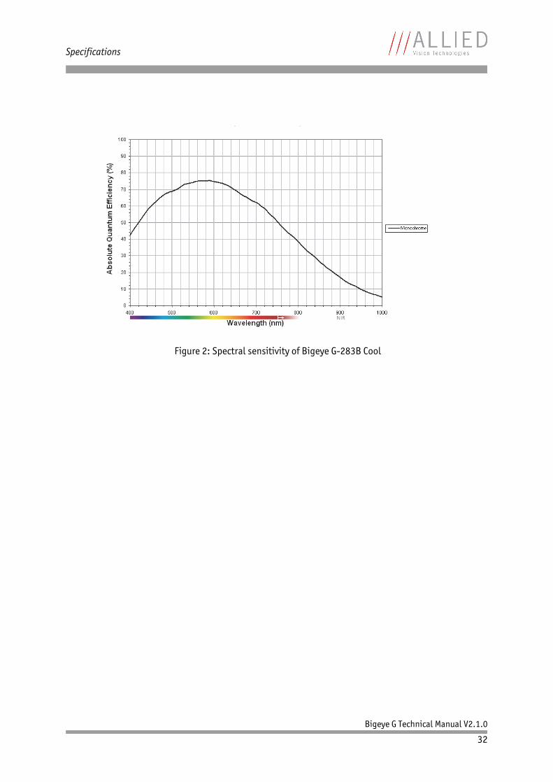
Spectral sensitivity
Note
All measurements were done without protection glass / without a filter.
The margin of error of the QE values is 10%.
This is due to:
• Manufacturing tolerance of the sensor• Uncertainties in the measuring equipment itself
(Ulbricht-Kugel/Ulbricht sphere, optometer, etc.)
Figure 1: Spectral sensitivity of Bigeye G-132B Cool
Specifications
Bigeye G Technical Manual V2.1.0
32
Figure 2: Spectral sensitivity of Bigeye G-283B Cool

Specifications
Bigeye G Technical Manual V2.1.0
33
Figure 3: Spectral sensitivity of Bigeye G-629B Cool

Specifications
Bigeye G Technical Manual V2.1.0
34
Figure 4: Spectral sensitivity of Bigeye G-1100B Cool

Filters and lenses
Bigeye G Technical Manual V2.1.0
35
Filters and lenses
Filters
• Monochrome cameras are equipped with a protection glass (without IR cut filter): Transmission > 99 % between 450 nm and 700 nm.Anti-reflective coating on both sides.
• NIR cameras: Bigeye G-132B NIR Cool and Bigeye G-629B NIR Cool cameras are equipped with a protection glass: Transmission > 98 % between 700 nm and 1700 nm. Anti-reflective coating on both sides.
Camera lenses
AVT offers different lenses from a variety of manufacturers.
The following tables list selected image formats in width x height depending on the camera type, the distance and the focal length of the lens.
www
For more information go to:
http://www.alliedvisiontec.com/emea/products/accessories/lenses.html
Note
Lenses with focal lengths < 8 mm may show shading on the edges of the image due to microlenses on the sensor's pixels.
Focal length f / mmfor Bigeye G-132
Object at distance = 500 mmWidth x Height / mm2
Object at distance = 1000 mmWidth x Height / mm2
4.8 852 x 681 1713 x 1368
6.0 680 x 543 1368 x 1093
6.5 627 x 501 1263 x 1009
8 508 x 406 1024 x 818
10 405 x 323 818 x 653
12 336 x 268 680 x 543
16 250 x 200 508 x 406
Table 7: Focal length vs. field of view (Bigeye G-132)

Filters and lenses
Bigeye G Technical Manual V2.1.0
36
25 157 x 125 322 x 257
35 110 x 88 228 x 182
50 74 x 59 157 x 125
75 47 x 37 102 x 81
90 38 x 30 84 x 67
Focal length f / mmfor Bigeye G-283
Object at distance = 500 mmWidth x Height / mm2
Object at distance = 1000 mmWidth x Height / mm2
4.8 1104 x 949 2218 x 1907
6.0 881 x 757 1773 x 1524
6.5 812 x 698 1635 x 1406
8 658 x 566 1327 x 1141
10 524 x 451 1059 x 911
12 435 x 374 881 x 757
16 324 x 278 658 x 566
25 203 x 175 417 x 359
35 142 x 122 295 x 254
50 96 x 83 203 x 175
75 61 x 52 132 x 113
90 49 x 42 108 x 93
Table 8: Focal length vs. field of view (Bigeye G-283)
Focal length f / mmfor Bigeye G-629
Object at distance = 500 mmWidth x Height / mm2
Object at distance = 1000 mmWidth x Height / mm2
14 960 x 640 1947 x 1298
18 740 x 494 1508 x 1005
21 631 x 420 1289 x 859
28 466 x 311 960 x 640
35 367 x 245 762 x 508
50 249 x 166 525 x 350
85 135 x 90 298 x 198
Table 9: Focal length vs. field of view (Bigeye G-629)
Focal length f / mmfor Bigeye G-132
Object at distance = 500 mmWidth x Height / mm2
Object at distance = 1000 mmWidth x Height / mm2
Table 7: Focal length vs. field of view (Bigeye G-132)

Filters and lenses
Bigeye G Technical Manual V2.1.0
37
100 111 x 74 249 x 166
135 75 x 50 177 x 118
180 49 x 33 126 x 84
300 18 x 12 65 x 43
400 7 x 5 41 x 28
Focal length f / mmfor Bigeye G-1100
Object at distance = 500 mmWidth x Height / mm2
Object at distance = 1000 mmWidth x Height / mm2
14 1257 x 837 2551 x 1699
18 970 x 646 1976 x 1316
21 826 x 550 1689 x 1124
28 611 x 407 1257 x 837
35 481 x 320 999 x 665
50 326 x 217 688 x 458
85 177 x 118 390 x 260
100 145 x 96 326 x 217
135 98 x 65 232 x 155
180 64 x 43 165 x 110
300 24 x 16 85 x 56
400 9 x 6 54 x 36
Table 10: Focal length vs. field of view (Bigeye G-1100)
Focal length f / mmfor Bigeye G-629
Object at distance = 500 mmWidth x Height / mm2
Object at distance = 1000 mmWidth x Height / mm2
Table 9: Focal length vs. field of view (Bigeye G-629)
Camera dimensions
Bigeye G Technical Manual V2.1.0
38
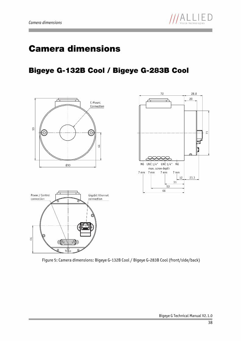
Camera dimensions
Bigeye G-132B Cool / Bigeye G-283B Cool
Figure 5: Camera dimensions: Bigeye G-132B Cool / Bigeye G-283B Cool (front/side/back)

Camera dimensions
Bigeye G Technical Manual V2.1.0
39
Bigeye G-629B Cool
Figure 6: Camera dimensions: Bigeye G-629B Cool (front/side/back)

Camera dimensions
Bigeye G Technical Manual V2.1.0
40
Bigeye G-1100B Cool
Figure 7: Camera dimensions: Bigeye G-1100B Cool (front/side/back)

Camera interfaces
Bigeye G Technical Manual V2.1.0
41
Camera interfacesThis chapter gives you information on Gigabit Ethernet port, inputs and outputs and trigger features.
Gigabit Ethernet port
The Gigabit Ethernet port conforms to the IEEE 802.3 1000BASE-T standard for Gigabit Ethernet over copper. We recommend connecting the Bigeye G using Category 5e or better patch cables and connectors for best performance.
Note
For a detailed description of the camera interfaces(GigE, I/O connector, status LEDs), and operating instruc-tions see the Manta/Bigeye G Hardware Installation Guide (How to install a GigE camera: Manta and Bigeye G), Chapter Camera interfaces.
Read all Notes and Cautions in the Manta/Bigeye G Hardware Installation Guide (How to install a GigE camera: Manta and Bigeye G), before using any interfaces.
www
For accessories like cables see:
http://www.alliedvisiontec.com/emea/products/accessories/gige-accessories.html
Note
Cable lengths up to 100 m are supported.
The 8-pin RJ45 (8P8C) connector has the pin assignment according to the Ethernet standard (IEEE 802.3 1000BASE-T).
The GigE port of a Bigeye G camera is screw-lockable.
AccessoriesCables are available from AVT:
http://www.alliedvisiontec.com/emea/products/accesso-ries/gige-accessories.html
Ask your local dealer for more details.

Camera interfaces
Bigeye G Technical Manual V2.1.0
42
Camera I/O connector pin assignment
Note
The I/O port of a Bigeye G camera is different to the one provided with a Bigeye P camera.
Bigeye G cameras have a 20-pin Mini D Ribbon (MDR) shielded I/O connector with screw-locks.
Figure 8: 20-pin Mini D Ribbon (MDR) shielded I/O connector
Pin Signal Direction Level Description
1 External Power --- +12 V DC Power supply
2 External GND --- GND External Ground
3 External Power --- +12 V DC Power supply
4 External GND --- GND External Ground
5 Camera Out 4 Out 3.3 V TTL, active low Camera Output 4
6 --- --- --- Reserved
7 RxD 1 In RS232 Terminal Receive Data
8 TxD 1 Out RS232 Terminal Transmit Data
9 Camera In 3 In Max. 24.0 V Camera Input 3(GP In 3)
10 Camera In GND In Common GND for inputs
Camera Common Input Ground (In GND)
11 Camera In 1 In Max. 24.0 V Camera Input 1 (GP In 2)
12 Camera Out 3 Out Open emitter,max. 20 mA
Camera Output 3(GP Out 3)
13 Camera Out Power
In Common VCC for out-puts max. 30 V DC
External Power for dig-ital outputs (OutVCC)
14 Camera Out 1 Out Open emitter,max. 20 mA
Camera Output 1(GP Out 1)
Table 11: Camera I/O connector pin assignment (HD20 Mini D Ribbon)

Camera interfaces
Bigeye G Technical Manual V2.1.0
43
Control signals
The inputs and outputs of the camera can be configured by software. The differ-ent modes are described below.
Inputs
15 Camera Out 2 Out Open emitter,max. 20 mA
Camera Output 2(GP Out 2)
16 Camera In 2 In Max. 24.0 V Camera Input 2(GP In 2)
17 Camera In 4 In 3.3 V TTL Camera Input 4 (GP In 4)
18 --- --- --- Reserved
19 RxD 2 In RS232 Terminal Receive Data 2
20 TxD 2 Out RS232 Terminal Transmit Data 2
Figure 9: Input block diagram
Pin Signal Direction Level Description
Table 11: Camera I/O connector pin assignment (HD20 Mini D Ribbon)
Polarity
selectablevia software
Input state
Input signalOpto-
Coupler
LP filter

Camera interfaces
Bigeye G Technical Manual V2.1.0
44
Input/output pin controlAll input and output signals running over the camera I/O connector are con-trolled by the I/O strobe commands. See AVT GigE GenICam Feature Descrip-tion and AVT GigE Vision Cameras.
Outputs
Output features are configured by software. Any signal can be placed on any output.
The main features of output signals are described below:
Note
For a general description of the outputs and warnings see the AVT GigE Installation Manual.
Signal Description
GPO Configured to be a general purpose output, control of which is assigned to SyncOutGpoLevels.
AcquisitionTriggerReady Active once the camera has been recognized by the host PC and is ready to start acquisition.
FrameTriggerReady Active when the camera is in a state that will accept the next frame trigger.
FrameTrigger Active when an image has been initiated to start. This is a logic trigger internal to the camera that is initiated by an external trigger or software trigger event.
Exposing Exposing – active for the duration of sensor expo-sure.
FrameReadout Active at during frame readout, i.e. the transfer-ring of image data from the CCD to camera memory.
Imaging Imaging is high when the camera image sensor is either exposing and/or reading out data.
Acquiring Active during an acquisition stream.
SyncIn1 Active when there is an external trigger at SyncIn1.
SyncIn2 Active when there is an external trigger at SyncIn2.
SyncIn3 Active when there is an external trigger at SyncIn3.
SyncIn4 Active when there is an external trigger at SyncIn4.
Strobe1 The output signal is controlled according to Strobe1 settings.
Table 12: Output signals

Camera interfaces
Bigeye G Technical Manual V2.1.0
45
Trigger timing diagramThe following diagram explains the trigger concept in general.
Figure 10: Output block diagram
Figure 11: Trigger timing diagram
GPO
Output signalOpto-
Coupler
Polarity
selectablevia software
Read from software
Output mode
selectablevia software
AcquisitionTriggerReadyFrameTriggerReady
FrameTriggerExposing
FrameReadoutAcquiring
Strobe1
SyncIn1SyncIn2SyncIn3SyncIn4

Camera interfaces
Bigeye G Technical Manual V2.1.0
46
Notes on triggering
Trigger definitions
Trigger rules
• The end of exposure will always trigger the next readout.• The end of exposure must always end after the current readout.
Term Definition
User trigger Trigger signal applied by the user (hardware trigger, software trigger).
Logic trigger Trigger signal seen by the camera internal logic (not visible to the user).
Tpd Propagation delay between the user trigger and the logic trigger.
Exposure High when the camera image sensor is integrating light.
Readout High when the camera image sensor is reading out data.
Trigger latency Time delay between the user trigger and the start of exposure.
Trigger jitter Variability in the trigger latency time.
Trigger ready Indicates to the user that the camera will accept the next trigger.
Registered exposure time
Exposure time value currently stored in the camera memory.
Exposure start delay Registered exposure time subtracted from the readout time and indicates when the next exposure cycle can begin such that the exposure will end after the current Readout.
Interline time Time between sensor row readout cycles.
Imaging High when the camera image sensor is either exposing and/or reading out data.
Idle Is high if the camera image sensor is not exposing and/or reading out data.
Table 13: Trigger definitions
Note
The user trigger pulse width should be at least three times the width of the trigger latency as indicated in Chapter Specifica-tions on page 15.

Camera interfaces
Bigeye G Technical Manual V2.1.0
47
• The start of exposure must always correspond with the interline time if Readout is true.
• Exposure start delay equals the Readout time minus the registered expo-sure time.
Triggering during the idle state
For applications requiring the shortest possible trigger latency and the smallest possible trigger jitter the user trigger signal should be applied when Imaging is false and Idle is true.
Triggering during the readout state
For applications requiring the fastest triggering cycle time such that the camera image sensor is exposing and reading out simultaneously:
Take care that the user trigger signal is applied as soon as a valid trigger ready is detected.
In this case, trigger latency and trigger jitter can be up to 1 line time since expo-sure must always begin on an interline boundary.
Description of the data path
Bigeye G Technical Manual V2.1.0
48
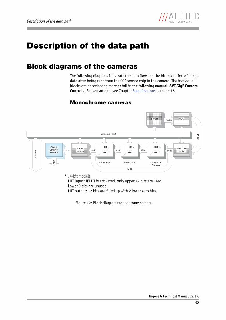
Description of the data path
Block diagrams of the camerasThe following diagrams illustrate the data flow and the bit resolution of image data after being read from the CCD sensor chip in the camera. The individual blocks are described in more detail in the following manual: AVT GigE Camera Controls. For sensor data see Chapter Specifications on page 15.
Monochrome cameras
Figure 12: Block diagram monochrome camera
Gigabit Ethernet interface
16 bitFrame
memory 14 bit LUT
12 12
Sensor AnalogADC
Camera control
HIR
OSE
I/O
Luminance LuminanceGamma
GigE Luminance
12 bit LUT
12 1212 bit
LUT
12 1214 bit
Horizontal binning
14*bit
14 bit
* 14-bit models:LUT input: If LUT is activated, only upper 12 bits are used.Lower 2 bits are unused.LUT output: 12 bits are filled up with 2 lower zero bits.
Description of the data path
Bigeye G Technical Manual V2.1.0
49
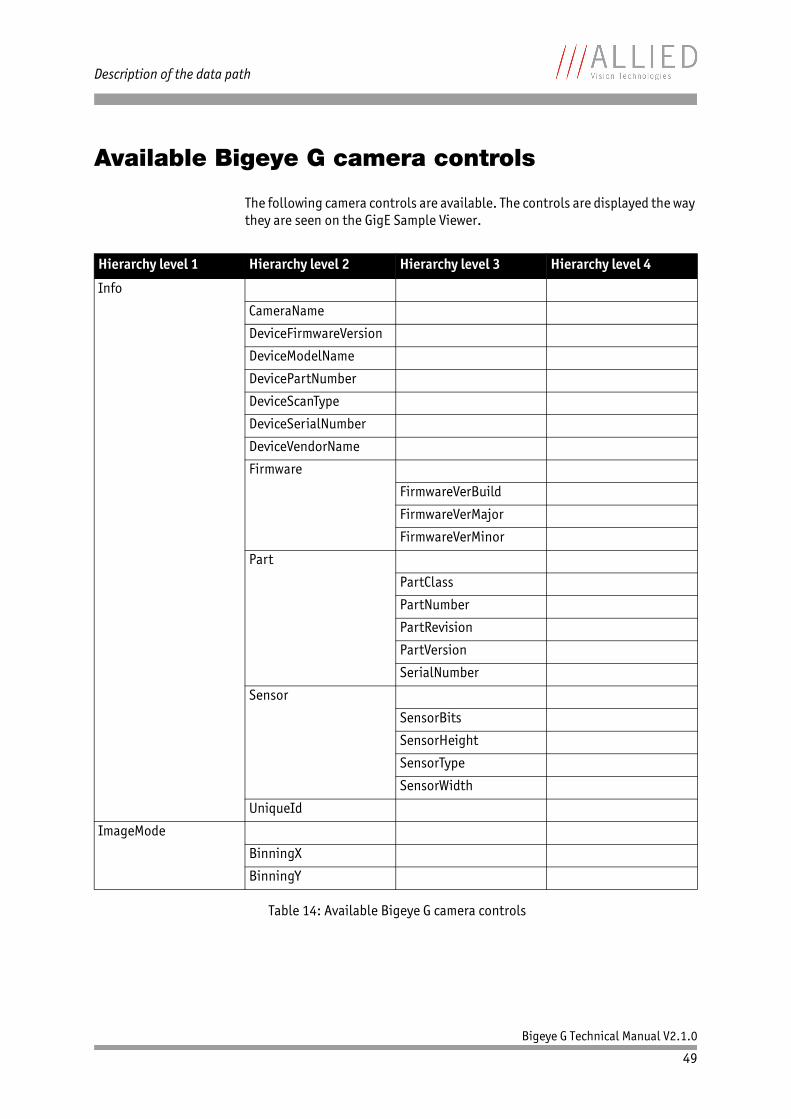
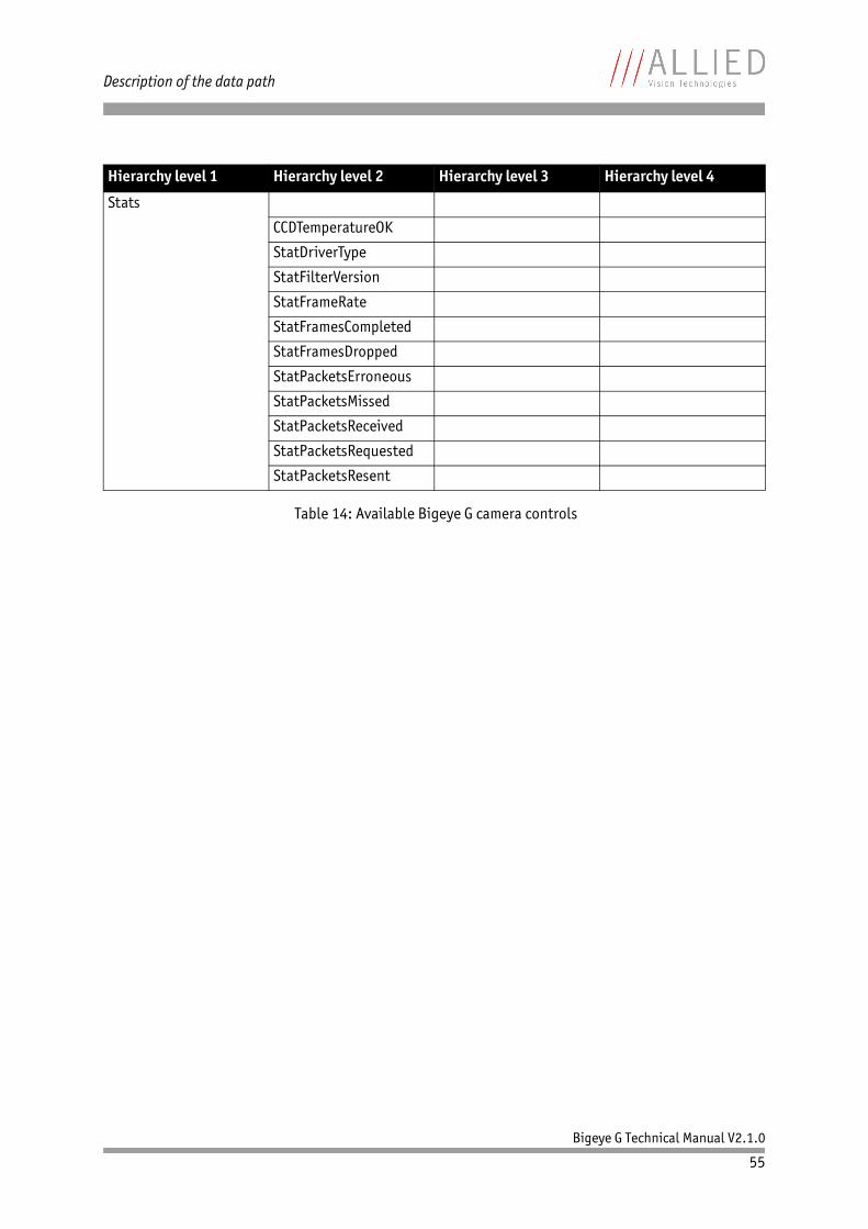
Available Bigeye G camera controls
The following camera controls are available. The controls are displayed the way they are seen on the GigE Sample Viewer.
Hierarchy level 1 Hierarchy level 2 Hierarchy level 3 Hierarchy level 4
Info
CameraName
DeviceFirmwareVersion
DeviceModelName
DevicePartNumber
DeviceScanType
DeviceSerialNumber
DeviceVendorName
Firmware
FirmwareVerBuild
FirmwareVerMajor
FirmwareVerMinor
Part
PartClass
PartNumber
PartRevision
PartVersion
SerialNumber
Sensor
SensorBits
SensorHeight
SensorType
SensorWidth
UniqueId
ImageMode
BinningX
BinningY
Table 14: Available Bigeye G camera controls

Description of the data path
Bigeye G Technical Manual V2.1.0
50
Acquisition
Trigger
AcqEndAcqEndTriggerEvent
AcqEndTriggerMode
AcqRecAcqRecTriggerEvent
AcqRecTriggerMode
AcqStartAcqStartTriggerEvent
AcqStartTriggerMode
FrameRate
FrameStartFrameStartTriggerDelay
FrameStartTriggerEvent
FrameStartTriggerMode
FrameStartTriggerOverlap
FrameStartTriggerSoftware
AcquisitionAbort
AcquisitionFrameCount
AcquisitionMode
AcquisitionStart
AcquisitionStop
RecorderPreEventCount
ImageFormat
ROI
Height
RegionX
RegionY
Width
PixelFormat
TotalBytesPerFrame
Hierarchy level 1 Hierarchy level 2 Hierarchy level 3 Hierarchy level 4
Table 14: Available Bigeye G camera controls

Description of the data path
Bigeye G Technical Manual V2.1.0
51
ControlsDSP
DSPSubregionBottom
DSPSubregionLeft
DSPSubregionRight
DSPSubregionTop
Gamma
ExposureExposureMode
ExposureValue
GainGainValue
IODMode
Iris
IrisAutoTarget
IrisMode
IrisVideoLevel
IrisVideoLevelMax
IrisVideoLevelMin
LUTControl
LUTSelector
LUTMode
LUTEnable
LUTIndex
LUTValue
LUTLoad
LUTSave
LUTInfo
LUTAddress
LUTSizeBytes
LUTBitDepthIn
LUTBitDepthOut
Shutter
Hierarchy level 1 Hierarchy level 2 Hierarchy level 3 Hierarchy level 4
Table 14: Available Bigeye G camera controls
Note
This feature is implemented in the firmware, but is not applicable due to missing lenses that may support this feature.
Note
Only available on Bigeye G-629B

Description of the data path
Bigeye G Technical Manual V2.1.0
52
EventControls
EventID
EventAcquisitionStart
EventAcquisitionEnd
EventFrameTrigger
EventExposureEndEventAcquisitionRecordTrigger
EventSyncIn1Rise
EventSyncIn1Fall
EventSyncIn2Rise
EventSyncIn2Fall
EventSyncIn3Rise
EventSyncIn3Fall
EventSyncIn4Rise
EventSyncIn4Fall
EventOverflow
EventError
EventNotification
EventSelector
EventsEnable1
ConfigFile
ConfigFileIndex
ConfigFileLoad
ConfigFilePowerUp
ConfigFileSave
Hierarchy level 1 Hierarchy level 2 Hierarchy level 3 Hierarchy level 4
Table 14: Available Bigeye G camera controls

Description of the data path
Bigeye G Technical Manual V2.1.0
53
GigE
BandwidthCtrlMode
ChunkModeActive
NonImagePayloadSize
PayloadSizeStreamFrameRateConstrain
Ethernet
DeviceEthAddress
HostEthAddress
IP
DeviceIPAddress
HostIPAddress
GvcpRetries
Gvsp
GvspLookbackWindow
GvspResendPercent
GvspRetries
GvspSocketBuffersCount
GvspTimeout
HeartbeatInterval
HeartbeatTimeout
Multicast
MulticastEnable
MulticastIPAddress
PacketSize
StreamBytesPerSecond
StreamHold
StreamHoldCapacity
StreamHoldEnable
Timestamp
TimeStampFrequency
TimeStampReset
TimeStampValueHi
TimeStampValueLatch
TimeStampValueLo
Hierarchy level 1 Hierarchy level 2 Hierarchy level 3 Hierarchy level 4
Table 14: Available Bigeye G camera controls

Description of the data path
Bigeye G Technical Manual V2.1.0
54
IO
StatusLed1
StatusLedInvert
StatusLedMode
StatusLedGpoLevels
Strobe
1Strobe1ControlledDuration
Strobe1Delay
Strobe1Duration
Strobe1Mode
SyncIn1
SyncInGlitchFilter
SyncIn2
SyncInGlitchFilter
SyncIn3
SyncInGlitchFilter
SyncIn4
SyncInGlitchFilter
SyncInLevels
SyncOut1
SyncOut1Invert
SyncOut1Mode
SyncOut2
SyncOut2Invert
SyncOut2Mode
SyncOut3
SyncOut3Invert
SyncOut3Mode
SyncOut4
SyncOut4Invert
SyncOut4Mode
SyncOutGpoLevels
Hierarchy level 1 Hierarchy level 2 Hierarchy level 3 Hierarchy level 4
Table 14: Available Bigeye G camera controls
Description of the data path
Bigeye G Technical Manual V2.1.0
55
Stats
CCDTemperatureOK
StatDriverType
StatFilterVersion
StatFrameRate
StatFramesCompleted
StatFramesDropped
StatPacketsErroneous
StatPacketsMissed
StatPacketsReceived
StatPacketsRequested
StatPacketsResent
Hierarchy level 1 Hierarchy level 2 Hierarchy level 3 Hierarchy level 4
Table 14: Available Bigeye G camera controls

Description of the data path
Bigeye G Technical Manual V2.1.0
56
Frame memory
An image is normally captured and transmitted in consecutive steps. The image is taken, read out from the sensor, digitized and sent over the Gigabit Ethernet network.
Bigeye G cameras are equipped with 32 MByte of RAM. The table below shows how many frames can be stored by each model.
The memory operates according to the FIFO (first in, first out) principle. This makes addressing for individual images unnecessary.
Note
The number of frames (StreamHoldCapacity) depends on resolution and pixel format. The listed number of frames is valid for full resolution and Mono8/Bayer8.
Model Memory size Pixel format/resolution
Bigeye G-132B Cool 32 MB memory: 25 frames
Mono8/full resolution
Bigeye G-283B Cool 32 MB memory: 11 frames
Bigeye G-629B Cool 32 MB memory: 5 frames
Bigeye G-1100B Cool 32 MB memory: 3 frames
Table 15: Image memory size (typical; see note above)

Bigeye G Technical Manual V2.1.0
57
Index
Index
A
acquiring (signal)..................................... 44acquisition stream .................................... 44AcquisitionTriggerReady (signal)................. 44
B
Bigeye G cameras...................................... 12Bigeye G GigE cameras ............................... 12Bigeye G-1100B Cool............................ 27, 40Bigeye G-132B Cool ............................. 15, 38Bigeye G-132B NIR Cool ............................. 15Bigeye G-283B Cool ............................. 19, 38Bigeye G-629B Cool .................................. 39block diagram
monochrome camera ........................... 48block diagrams
cameras ............................................ 48
C
camera dimensions ......................... 38, 39, 40camera interfaces ..................................... 41camera lenses .......................................... 35cameras
block diagram .................................... 48CE.......................................................... 14common GND
inputs............................................... 42
D
data path ................................................ 48declaration of conformity ........................... 14document history ....................................... 7duration of sensor exposure........................ 44
E
EMVA ..................................................... 12European Machine Vision Association (EMVA) . 12exposing (signal) ..................................... 44exposing (trigger) .................................... 46exposure cycle (trigger)............................. 46exposure start delay (signal) ...................... 46
exposure time value (trigger) ..................... 46exposure (definition) ................................ 46external GND ........................................... 42external trigger........................................ 44external trigger at SyncIn1......................... 44external trigger at SyncIn2......................... 44
F
focal length............................................. 35frame readout.......................................... 44frame trigger ........................................... 44FrameReadout (signal) .............................. 44FrameTrigger (signal)................................ 44FrameTriggerReady (signal)........................ 44
G
general purpose output (GPO)..................... 44GenICam................................................. 12Gigabit Ethernet....................................... 12GigE....................................................... 12GigE Vision .............................................. 12GND for ext. power.................................... 42GPO (general purpose output)..................... 44
I
idle (signal) ............................................ 46imaging (signal) ................................. 44, 46input
block diagram .................................... 43inputs
common GND ..................................... 42general ............................................. 43in detail ............................................ 43
integrating light (trigger) .......................... 46interline boundary.................................... 47interline time (signal) ............................... 46
K
key benefits............................................. 12

Bigeye G Technical Manual V2.1.0
58
Index
L
legal notice ............................................... 2logic trigger ............................................ 44logic trigger (definition) ............................ 46LUTControl .............................................. 51
M
monochrome camerablock diagram .................................... 48
O
outputblock diagram .................................... 45signals.............................................. 44
outputs .................................................. 44general ............................................. 43
P
PoE..........................................15, 19, 23, 27propagation delay (trigger) ........................ 46
R
reading out data (imaging)......................... 46reading out data (readout) ......................... 46readout (definition) .................................. 46registered exposure time (signal) ................ 46RoHS (2011/65/EU).................................. 14RS232 ............................................... 42, 43RxD_RS232 ........................................ 42, 43
S
sensor row readout cycles........................... 46software trigger ....................................... 44specifications .......................................... 15spectral sensitivity
Bigeye G-1100B.................................. 34Bigeye G-132B.................................... 31Bigeye G-283B.................................... 32Bigeye G-629B.................................... 33
start acquisition ....................................... 44Strobe1 (signal) ....................................... 44styles ....................................................... 9symbols .................................................... 9SyncIn1 (signal)....................................... 44SyncIn2 (signal)....................................... 44
SyncIn3 (signal)....................................... 44SyncIn4 (signal)....................................... 44SyncOutGpoLevels .................................... 44system components .................................. 35
T
time delay (trigger) .................................. 46timing diagram
trigger .............................................. 45Tpd (definition) ....................................... 46trigger
timing diagram................................... 45trigger definitions .................................... 46trigger jitter (definition)............................ 46trigger latency time .................................. 46trigger latency (definition)......................... 46trigger ready (signal) ................................ 46trigger rules ............................................ 46types
Bigeye G GigE cameras ......................... 12
U
user trigger (definition)............................. 46