AvrUsb500v2 -- an open source Atmel AVR Programmer, stk500 V2
12
Home | Electronics | Tuxkid | E-cards | Linux & Computer stuff | Graphics, Film & Animation | Photos | Online-Shop AvrUsb500v2 -- an open source Atmel AVR Programmer, stk500 V2 compatible, with USB interface Abstract: This is a re-design of the popular avrusb500 programmer. The second version of avrusb500: avrusb500v2. When I started to develop the original avrusb500 during spring 2005 I had a modern programmer in mind. It should have a USB interface but have no "chicken and egg problem". That is: you should be able to build it from scratch without the need of another programmer to load the initial firmware. It should also be device independent. That is: should be possible to program Content: What is stk500 version 2? How to use this USB AVR programmer Solving the chicken and egg problem The hardware The avrusb500v2 software Soldering SMD chips Testing the hardware The bridge connector (CONN6) BitBang loading of the final firmware Using the USB AVR programmer Conclusions References By Guido Socher <guido_at_tuxgraphics.org>
Transcript of AvrUsb500v2 -- an open source Atmel AVR Programmer, stk500 V2
Home | Electronics | Tuxkid | E-cards | Linux & Computer stuff | Graphics, Film & Animation | Photos | Online-Shop
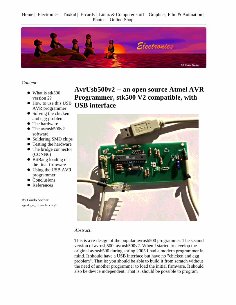
AvrUsb500v2 -- an open source Atmel AVRProgrammer, stk500 V2 compatible, withUSB interface
Abstract:
This is a re-design of the popular avrusb500 programmer. The secondversion of avrusb500: avrusb500v2. When I started to develop theoriginal avrusb500 during spring 2005 I had a modern programmer inmind. It should have a USB interface but have no "chicken and eggproblem". That is: you should be able to build it from scratch withoutthe need of another programmer to load the initial firmware. It shouldalso be device independent. That is: should be possible to program
Content:
What is stk500version 2? How to use this USBAVR programmer Solving the chickenand egg problem The hardware The avrusb500v2software Soldering SMD chipsTesting the hardware The bridge connector(CONN6) BitBang loading ofthe final firmware Using the USB AVRprogrammer Conclusions References
By Guido Socher <guido_at_tuxgraphics.org>
current and future AVR microcontrollers without the need to modifythe programmer for every new chip. The result was avrusb500.
The new avrusb500v2 has all the functionallity of the previous versionand contains a number of new features based on suggestions fromreaders and customers:
The led indicates now if the programmer is correctly connectedto the target. This is a very useful feature as it is often not soobvious which way round the connector should fit onto thetarget board.
A 1MHz emergency clock signal is provided. This can be usedto recover a chip which was accidentally programmed with thewrong fuses.
Explanation: Atmel calls their configuration bits "Fuses". They have howevernothing in common with traditional fuses. They are bit patterns which can be used toconfigure the startup behavior of the microcontroller similar to the BIOS in a PC.They can be modified as needed at any time (they don’t burn like a real fuse) butwithin limits: If you accidentally program the AVR fuses for an external crystal butthe hardware does not have such a crystal or the wrong crystal type then yourhardware will be "dead". It is possible to recover such "dead" hardware byconnecting the 1MHz clock output to the XTAL1 pin of the AVR and thenre-program the fuses to the correct value.
The firmware for avrusb500v2 is again open source and programmedin C.
A link to the older (version 1) avrusb500 can be found at the end ofthis article.
The avrusb500v2 is available as a kit from the online shop:http://shop.tuxgraphics.org
_________________ _________________ _________________
What is stk500 version 2?
Until not so long ago many programmers had specific knowledge about the possible targetmicrcocontrollers burned into the programmer. stk500 is a development board from atmel but itworks also as programmer and the communication protocol between your PC and that programmeris therefore often called just stk500. stk500 version 1 was such a device dependent protocol. Itneeded updates for every new programmer that came out. At last Atmel had a good idea anddeveloped a protocol which had some more generic procedures. This was then called stk500 version2 and the exact specification is AVR068. There is also a more recent variant called AVR069.
The stk500 AVR068 specification needs no longer device dependent data structures in the
programmer hardware. All device dependent logic is now in the programmer software running onthe PC. As of today avrstudio (for windows) and avrdude (for multiple OSs including Linux)support this version 2 of the stk500 protocol.
The physical hardware interface to the PC is USB. This way we can build a fast and modernprogrammer which can be used under Linux, BSD, Windows, MacOS X and others.
How to use this USB AVR programmer
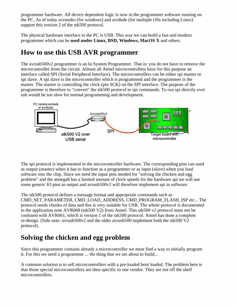
The avrusb500v2 programmer is an In System Programmer. That is: you do not have to remove themicrocontroller from the circuit. Almost all Atmel microcontrollers have for this purpose aninterface called SPI (Serial Peripheral Interface). The microcontrollers can be either spi master orspi slave. A spi slave is the microcontroller which is programmed and the programmer is themaster. The master is controlling the clock (pin SCK) on the SPI interface. The purpose of theprogrammer is therefore to "convert" the stk500 protocol to spi commands. To run spi directly overusb would be too slow for normal programming and development.
The spi protocol is implemented in the microcontroller hardware. The corresponding pins can usedas output (master) when it has to function as a programmer or as input (slave) when you loadsoftware into the chip. Since we need the input pins needed for "solving the chicken and eggproblem" and the atmega8 has a limited amount of clock speeds for the hardware spi we will usesome generic IO pins as output and avrusb500v2 will therefore implement spi in software.
The stk500 protocol defines a message format and appropriate commands such asCMD_SET_PARAMETER, CMD_LOAD_ADDRESS, CMD_PROGRAM_FLASH_ISP etc... Theprotocol sends chunks of data and this is very suitable for USB. The whole protocol is documentedin the application note AVR068 (stk500 V2) from Atmel. This stk500 v2 protocol must not beconfused with AVR061, which is version 1 of the stk500 protocol. Atmel has done a completere-design. (Side note: avrusb500v2 and the older avrusb500 implement both the stk500 V2protocol).
Solving the chicken and egg problem
Since this programmer contains already a microcontroller we must find a way to initially programit. For this we need a programmer ... the thing that we are about to build...
A common solution is to sell microcontrollers with a pre-loaded boot loaded. The problem here isthat those special microcontrollers are then specific to one vendor. They are not off the shelfmicrocontrollers.
For the usb interface we use a FT232rl chip. This chip has an interesting mode called "bit-bang"mode. I have written a source code library called ftdibb (only 2 files .c and .h, available fromhttp://tuxgraphics.org/~guido/) which implements this bitbang mode on top of the libUSB library.LibUSB (http://libusb.sourceforge.net) uses the /proc file system to send and receive custom usbmessages to any usb device on the usb bus. A slight drawback is that this requires root permissionsunder Linux it is a slow process as we will send very short messages. Initially (when there is nofirmware on loaded in the microcontroller) we have absolutely no storage place and no logic in theprogrammer. We must send all the commands directly from the PC, bit by bit. USB is fast whenyou send long chunks of data but it is very slow when you send only 1 bit at a time.
This is however acceptable because:
The initial firmware needs to be loaded only once. It saves us from having to get first a different programmer to load the initial firmware into thisprogrammer There is no customer lock-in with special AVR chips. Any of the shelf atmega8/atmega88will work.
In other words the avrusb500v2 consists really of two programmers: One slow internal for theinitial loading of the firmware and the actual avrusb500v2 programmer which is a very fast andstk500 V2 based programmer for every day use.
I called the bitbang programmer for the initial loading "bbpg". I have modified the uisp programmersoftware for this purpose. You need to download uisp-20050207.tar.gz and then apply theuisp-20050207-usb-bbpg-patch.txt patch (cd uisp-20050207;patch -p1 <uisp-20050207-usb-bbpg-patch.txt ) or you can take the already patched sources(uisp-20050207-usb-bbpg.tar.gz, download at the end). Libusb needs to be installed before youcompile the bbpg programmer. The avrusb500v2-X.Y.tar.gz package contains also a patched andpre-compiled binary. If you want to save some compile time then try this one first. You must namethis version of uisp "uisp_bbpg". This is what the makefiles and scripts expect.
The CD which is sold from http://shop.tuxgraphics.org together with the parts for this programmercan also be used for the initial loading of the firmware. It has the additional advantage that you cando this from the CD without root permissions.
The hardware
The specification from Atmel for the STK500 V2 communication protocol is 37 pages long. It ishowever not a problem to fit it into an atmega8 microcontroller. It fills about half of the availablememory.
Here is the schematic drawing. The right side is the usb to rs232 conversion circuit to provide usbconnectivity to the atmega8/atmega88. The whole circuit is self powered. That is: unlike may otherprogrammers you do not need additional pins to draw the power from the target circuit.
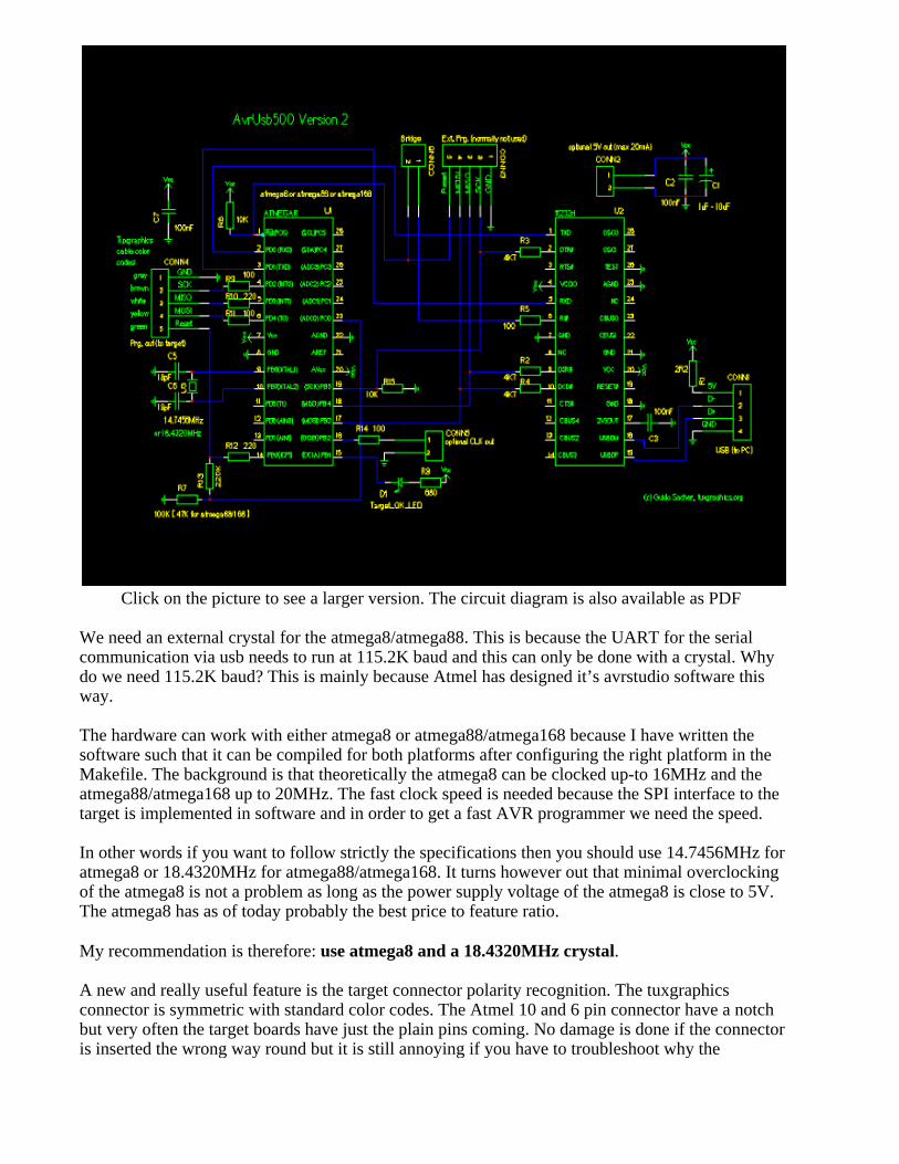
Click on the picture to see a larger version. The circuit diagram is also available as PDF
We need an external crystal for the atmega8/atmega88. This is because the UART for the serialcommunication via usb needs to run at 115.2K baud and this can only be done with a crystal. Whydo we need 115.2K baud? This is mainly because Atmel has designed it’s avrstudio software thisway.
The hardware can work with either atmega8 or atmega88/atmega168 because I have written thesoftware such that it can be compiled for both platforms after configuring the right platform in theMakefile. The background is that theoretically the atmega8 can be clocked up-to 16MHz and theatmega88/atmega168 up to 20MHz. The fast clock speed is needed because the SPI interface to thetarget is implemented in software and in order to get a fast AVR programmer we need the speed.
In other words if you want to follow strictly the specifications then you should use 14.7456MHz foratmega8 or 18.4320MHz for atmega88/atmega168. It turns however out that minimal overclockingof the atmega8 is not a problem as long as the power supply voltage of the atmega8 is close to 5V.The atmega8 has as of today probably the best price to feature ratio.
My recommendation is therefore: use atmega8 and a 18.4320MHz crystal.
A new and really useful feature is the target connector polarity recognition. The tuxgraphicsconnector is symmetric with standard color codes. The Atmel 10 and 6 pin connector have a notchbut very often the target boards have just the plain pins coming. No damage is done if the connectoris inserted the wrong way round but it is still annoying if you have to troubleshoot why the
programmer does not seem to work. avrusb500v2 has now an LED which goes on as soon as theconnector is correctly inserted. A main source of troubles is therefore eliminated. The connectionfrom the target reset pin to ADC0 is used for this purpose.
There is also and output for the 1MHz emergency clock signal (CONN5) and a 5V output to powera target (CONN2) if needed. Be however aware that there are no fuses or current limitingcomponents on CONN2. No more than 20mA should be taken from CONN2. If you want a fusedUSB power supply to power external hardware from the USB bus of you computer the I canrecommend the 5V mini power supply, USB(http://shop.tuxgraphics.org/electronic/microcontroller.html#usbPowerOnTheRoad).
The avrusb500v2 software
avrusb500v2 has this self boot-strapping feature which makes it possible for anybody to build thishardware with out the help of others to get the first firmware loaded. For this purpose theconnections between the MOSI, SCK, MISO pins and the ftdi chip are needed. Those pins wouldhowever also be needed if we would use the hardware SPI in the atmega chip towards the target.The old avrusb500 required therefore a 5 pin bridge cable. The new avrusb500v2 implements theSPI towards the target in software. Any pin can therefore be used as output towards the target. Justthe reset pin is, for safety reasons, connected and disconnected after the initial firmware loading.
To implement the SPI in software I started with hand optimized assembler but soon I found thatwell written C code can do the job too especially when a 18MHz crystal is used to clock theatmega. C-code is easier to read and maintain. SPI is a very simple interface. Programmer controlsthe clock line called SCK. At the rising clock edge the data is shifted on the MOSI pin fromprogrammer to target at on the MISO pin from target to programmer. In hardware this is easilyimplemented as a shift register. In software it can be done like this:
unsigned char i=128; // shift 8 bitunsigned char rval=0; // data read from targetwhile(i!=0){ // MOSI if (data&i){ PORTD|= 1<<PD4; }else{ // trans mit a zero PORTD &= ~(1<<PD4); } _delay_loop_1(d_sck_dur); // low clock duration // read MISO if(PIND & (1<<PIND3)){ rval|= i; } PORTD|= (1<<PD2); // SCK high _delay_loop_1(d_sck_dur); // SCK high pulse duration i=i>>1; PORTD &= ~(1<<PD2); // SCK low}
An additional advantage besides removing the 5 pin bridge cable is that we can do much morespeeds in software. The hardware spi has a frequency pre-scaler and this determines immediatelyhow many different SCK speeds can be implemented. In software there is no real limit (however itmakes no sense to implement an endless number).
The rest of the software (largest part of the software) is about the implementation of the stk500v2protocol towards the PC.
Soldering SMD chips
I have designed the hardware such that conventional parts can be used for almost all components.Only the ft232rl is a SMD chip. Its a very compact new chip but it has the problem that it comesonly in very tiny packages not usable for soldering at home. Especially if you have just a standardsoldering iron. The tuxgraphics online shop sells therefore the boards with this chip alreadysoldered on.
Testing the hardware
The software package (avrusb500v2-X.Y.tar.gz) contains a README.htm file. Please read it first.
I recommend to build the programmer in steps and and use the following test procedures at everystep in order to narrow down possible mistakes:
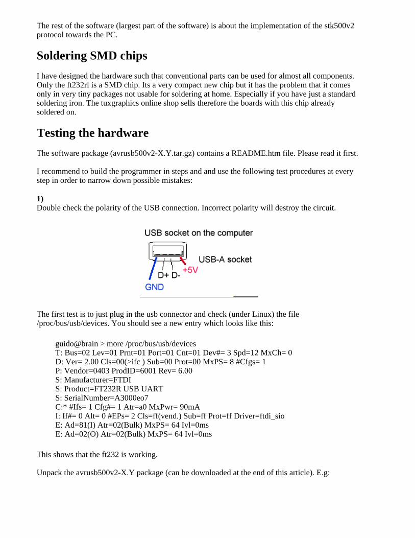
1) Double check the polarity of the USB connection. Incorrect polarity will destroy the circuit.
The first test is to just plug in the usb connector and check (under Linux) the file/proc/bus/usb/devices. You should see a new entry which looks like this:
guido@brain > more /proc/bus/usb/devicesT: Bus=02 Lev=01 Prnt=01 Port=01 Cnt=01 Dev#= 3 Spd=12 MxCh= 0D: Ver= 2.00 Cls=00(>ifc ) Sub=00 Prot=00 MxPS= 8 #Cfgs= 1P: Vendor=0403 ProdID=6001 Rev= 6.00S: Manufacturer=FTDIS: Product=FT232R USB UARTS: SerialNumber=A3000eo7C:* #Ifs= 1 Cfg#= 1 Atr=a0 MxPwr= 90mAI: If#= 0 Alt= 0 #EPs= 2 Cls=ff(vend.) Sub=ff Prot=ff Driver=ftdi_sioE: Ad=81(I) Atr=02(Bulk) MxPS= 64 Ivl=0msE: Ad=02(O) Atr=02(Bulk) MxPS= 64 Ivl=0ms
This shows that the ft232 is working.
Unpack the avrusb500v2-X.Y package (can be downloaded at the end of this article). E.g:
tar zxvf avrusb500v2-1.0.tar.gzcd avrusb500v2-1.0
Here you find two more test programs which test the microcontroller and the whole communicationto your PC. Load them also. How to do this is described in the README.htm file inside theavrusb500v2-X.Y package. You will basically just short circuit the bridge connector (CONN6) andexecute a command like
make load_test_1
This will load a test program into the atmega. but please have a look at the README file fordetails (command: more README.htm or open it in a web-browser).
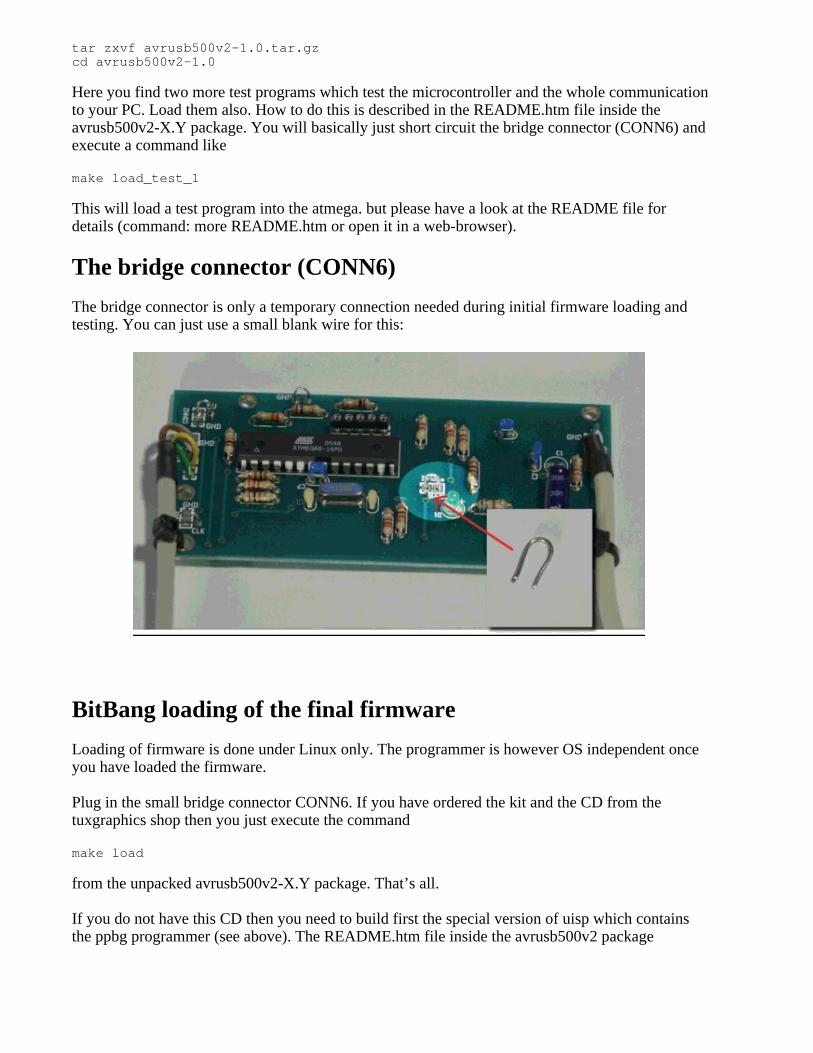
The bridge connector (CONN6)
The bridge connector is only a temporary connection needed during initial firmware loading andtesting. You can just use a small blank wire for this:
BitBang loading of the final firmware
Loading of firmware is done under Linux only. The programmer is however OS independent onceyou have loaded the firmware.
Plug in the small bridge connector CONN6. If you have ordered the kit and the CD from thetuxgraphics shop then you just execute the command
make load
from the unpacked avrusb500v2-X.Y package. That’s all.
If you do not have this CD then you need to build first the special version of uisp which containsthe ppbg programmer (see above). The README.htm file inside the avrusb500v2 package
describes this procedure also.
Loading of the firmware takes very long time due to the huge overhead you get on the USB buswhen you send just one bit at a time. You can calculate approximately 15minutes for loading and10minutes for verification.
Using the USB AVR programmer
This programmer is designed to be developed in a Linux environment. However once build it istruly OS independent. You can use it with the AVRstudio for windows or under Mac OSX or Linuxor BSD Unix ...
avrdude is the software needed to use the avrusb500 programmer under Linux or Max OS(http://savannah.nongnu.org/projects/avrdude/). You need version 5.X (or higher).
The command to load the code MyCode.hex into an ATmega8 would be:
avrdude -p m8 -c avrusb500 -e -U flash:w:MyCode.hex
The configuration file entry in the avrdude.conf file is:
default_serial = "/dev/ttyUSB0";#or#default_serial = "/dev/usb/tts/0";
# ... and further down:programmer id = "avrusb500"; desc = "Atmel AVR ISP V2 programmer from tuxgraphics"; type = stk500v2;;#
A very common mistake when programming AVR chips is to mis-configure accidentally the fusebits. This can easily lead to a situation where the oscillator does not function. Most of the AVRmicrocontrollers can however be recovered by supplying an external clock signal on the XTAL1pin and setting the fuse bytes to the correct values. Possibly using a low SCK frequency (the -Boption in avrdude):
Example: avrdude -B 10 -p m8 -c avrusb500 -u -v -U lfuse:w:0xTheValue:m
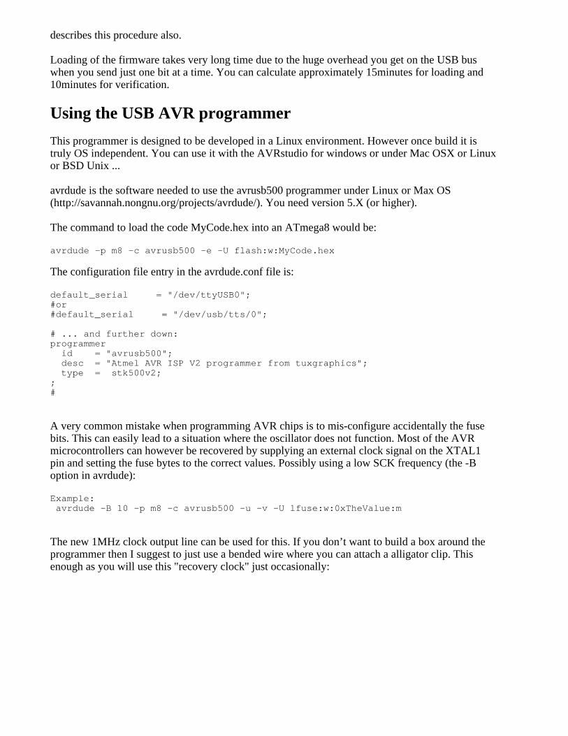
The new 1MHz clock output line can be used for this. If you don’t want to build a box around theprogrammer then I suggest to just use a bended wire where you can attach a alligator clip. Thisenough as you will use this "recovery clock" just occasionally:
I recommend also some kind of pull relief for the cables. A cheap and reliable solution is to usecable straps and tie the cables to the board.
Conclusions
This is a modern USB based AVR programmer which can be build from scratch without the need tofind a programmer to program the programmer.
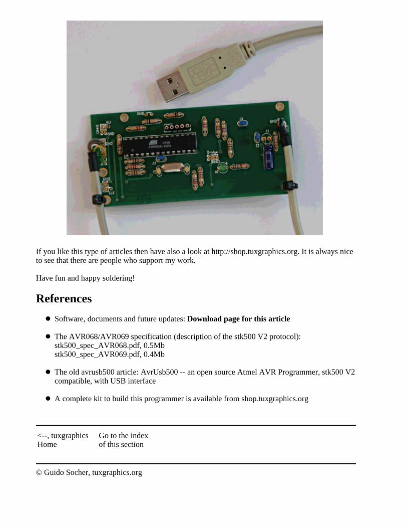
If you like this type of articles then have also a look at http://shop.tuxgraphics.org. It is always niceto see that there are people who support my work.
Have fun and happy soldering!
References
Software, documents and future updates: Download page for this article
The AVR068/AVR069 specification (description of the stk500 V2 protocol): stk500_spec_AVR068.pdf, 0.5Mbstk500_spec_AVR069.pdf, 0.4Mb
The old avrusb500 article: AvrUsb500 -- an open source Atmel AVR Programmer, stk500 V2compatible, with USB interface
A complete kit to build this programmer is available from shop.tuxgraphics.org
<--, tuxgraphicsHome
Go to the indexof this section
© Guido Socher, tuxgraphics.org

2007-05-31, generated by tuxgrparser version 2.55


![Atmel AVR XMEGA C Manual - Microchip Technology · 2017. 5. 5. · XMEGA C [MANUAL] 3 Atmel-8465H-AVR-XMEGA C-12/2014 Atmel-8465H-AVR-XMEGA C-Datasheet_12/2014 2. Overview The AVR](https://static.fdocuments.us/doc/165x107/6111be10dc2737184a43a022/atmel-avr-xmega-c-manual-microchip-technology-2017-5-5-xmega-c-manual-3.jpg)