AVR USBISP+ V4.0 for specialist(Model:AD-USBISP+...
8
NEWTC Co., Ltd. http://www.NEWTC-en.com AVR USBISP+ V4.0 for specialist(Model:AD-USBISP+ V4.0) NEWTC Co., Ltd. http://www.NEWTC-en.com Date : Oct. 1, 2010 1 Introduction to AD-USBISP+ V04 development equipment ISP (In System Programming ) development equipment for AVR It is possible to download and test any user written program to the internal program memory of AVR(Supports Flash Read/Write) Download is possible to any 8 bit AVR micro controller that supports ISP of ATMEGA2560, ATMEGA2561, ATMega128, ATMega32, ATMega16 and ATMega8 etc (3.3V/5V Compatible) This device can be used with 8051 compatible 89Sseries microcontrollers like AT89S52 and AT89S51 etc Supported S/W (Various lectures available at http://www.NEWTC-en.com webpage) Automatic downloading after compiling by ICC-AVR V6.xx, V7.xx, V8.xx CodeVision C Compiler Support V1.24.6 Commercial Release and above (V1.24.7F is not supported) Stable operation possible from V1.25x and above Support latest AVR STUDIO Version 4.18 ~ 4.13 1 / 8
Transcript of AVR USBISP+ V4.0 for specialist(Model:AD-USBISP+...

NEWTC Co., Ltd.http://www.NEWTC-en.com
AVR USBISP+ V4.0 for specialist(Model:AD-USBISP+ V4.0)
NEWTC Co., Ltd.
http://www.NEWTC-en.com
Date : Oct. 1, 2010
1 Introduction to AD-USBISP+ V04 development equipment
ISP (In System Programming ) development equipment for AVR
It is possible to download and test any user written program to the internal
program memory of AVR(Supports Flash Read/Write)
Download is possible to any 8 bit AVR micro controller that supports ISP of
ATMEGA2560, ATMEGA2561, ATMega128, ATMega32, ATMega16 and ATMega8
etc (3.3V/5V Compatible)
This device can be used with 8051 compatible 89Sseries microcontrollers
like AT89S52 and AT89S51 etc
Supported S/W (Various lectures available at http://www.NEWTC-en.com webpage)
Automatic downloading after compiling by ICC-AVR V6.xx, V7.xx, V8.xx
CodeVision C Compiler
Support V1.24.6 Commercial Release and above (V1.24.7F is not supported)
Stable operation possible from V1.25x and above
Support latest AVR STUDIO Version 4.18 ~ 4.13
1 / 8

NEWTC Co., Ltd.http://www.NEWTC-en.com
2 AD-USBISP+ V4.0 development equipment H/W
Connection between USB-ISP and AB-M128-A boards
2.1 ISP connector Pin out1row 6 pin
1. MOSI 2. MOSI 3. SCK 4. RST 5. GND 6. VTref
Two row 6 pin1. MISO 3. SCK 5. RST2. Vtref 4. MOSI 6. GND
Two row 10 pin1. MOSI 3. NC 5. RST 7. SCK 9. MISO2. Vtref 4. GND 6. GND 8. GND 10. GND※ PDI, PDO can be connected to 1st and 2nd pin of ATMega128 and AVR's
that do not have PDI,PDO can be connected using MOSI,MISO
※ Function of each pin
> MOSI Master output Slave input > MISO Master input Slave output
> SCK Master clock out > RST Reset signal
> Vtref Target board voltage > NC Not Connect
2 / 8

NEWTC Co., Ltd.http://www.NEWTC-en.com
2.2 How to use the standard 6P and 10P ConnectorAD-ISP-CVB converting board can be used to download to boards that are made with the standard 6P or 10P connector. Converting board is included with the price of USBISP but you need to buy it separately in case of USBISP-L.
3 Method to use Software
3.1 USB Driver Installation
1 Download the USB-ISP+V4.0 driver (Refer below URL) provided in the document
store of the NEWTC home page.
Home Page URL: http://www.NEWTC-en.com (Data center)
2 Device is detected when AD-USBISP+ V4.0 is connected to the computer USB
port. As shown in the picture, the device is visible under the port device category
My Computer Hardware Device Manager
In this picture it is shown as COM5, but it may be different on different Computer,
so please confirm before using the AD-USBISP+ V4.0
※ If you need to change the COM port, select the USB Serial Port, right click the
mouse and click propertiesPort settingsAdvancedCOM and change the
port number. (Refer below picture)
3 / 8

NEWTC Co., Ltd.http://www.NEWTC-en.com
3.2 Program Setting
3.2.1 Use from ICC-AVR
4 / 8
1
2
3
5
4
NEWTC Co., Ltd.http://www.NEWTC-en.com
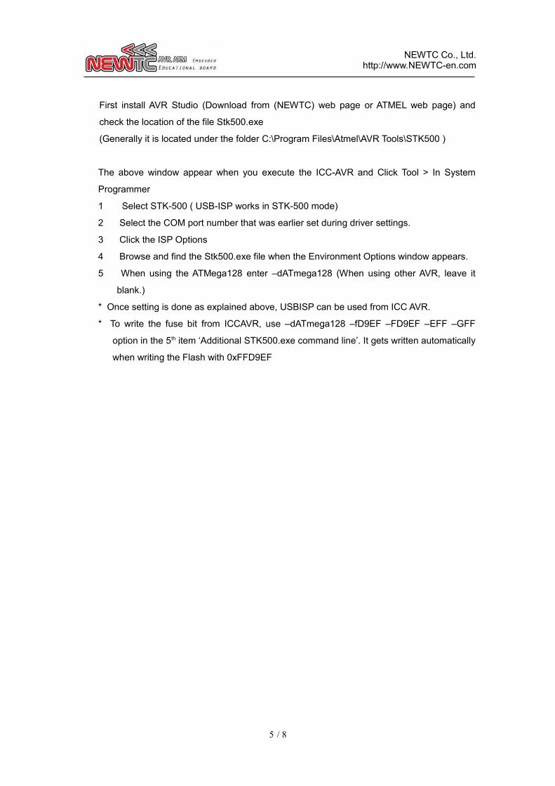
First install AVR Studio (Download from (NEWTC) web page or ATMEL web page) and
check the location of the file Stk500.exe
(Generally it is located under the folder C:\Program Files\Atmel\AVR Tools\STK500 )
The above window appear when you execute the ICC-AVR and Click Tool > In System
Programmer
1 Select STK-500 ( USB-ISP works in STK-500 mode)
2 Select the COM port number that was earlier set during driver settings.
3 Click the ISP Options
4 Browse and find the Stk500.exe file when the Environment Options window appears.
5 When using the ATMega128 enter –dATmega128 (When using other AVR, leave it
blank.)
* Once setting is done as explained above, USBISP can be used from ICC AVR.
* To write the fuse bit from ICCAVR, use –dATmega128 –fD9EF –FD9EF –EFF –GFF
option in the 5th item ‘Additional STK500.exe command line’. It gets written automatically
when writing the Flash with 0xFFD9EF
5 / 8

NEWTC Co., Ltd.http://www.NEWTC-en.com
3.2.2 Use from CodeVision AVR
3.2.3 Use from AVR STUDIO
6 / 8
1
2
3
1
2
3

NEWTC Co., Ltd.http://www.NEWTC-en.com
4 LED indication related
With USBISP+ V4.0, the LED indicator has become clearly defined. There are 4 LEDs in
Total, and you can see the individual function from 4 LEDs each. Each LED name is written
in outside of PCB with white silk screen.
1) USB LINK is turned on when USB is connected to PC correctly.
2) USB DATA will blink when PC and USB chip is transferring DATA correctly.
3) ISP DATA will blink when USBISP and target board is transferring DATA correctly.
4) ISP CONNECTOIN is turned on when target board is connected, and also this LED will
blink when the voltage of target board is abnormal(under 1.5V or over 6V)
5 Epilog
5.1 Product Enquiry and Thank you Note
We are thankful to you for buying NEWTC Co., Ltd product. Our company would put
maximum effort towards development to enhance the convenience of AVR users. If
you hope to use this module you will require handling microprocessor like AVRs. If you
intend to study further then you may either use the exercises included with the kit or
refer the lectures available in our web page.
5.2 Technical support web page
http://www.NEWTC-en.com
Various types of technical documents like AVR lectures, Electronics engineering
lectures , lectures on Robot manufacturing etc are available at the Technical Support
web page http://www.NEWTC-en.com. You may refer to the various useful files and
application programs etc that are updated on a regular basis. If you have any query
related to product A/S please write it without any hesitation in the Q&A section of our
web page. If you have any query related to product development send E mail to
([email protected]). Thank you.
7 / 8

NEWTC Co., Ltd.http://www.NEWTC-en.com
8 / 8
Reset
MOSI
SCK
MISO
MOSI
MISO
SCK
Reset