AVR Prog USB v2 manual - GM Electronic · PDF file5. BASCOM environment programming...
17
Programming Device Manual Booklet AVR Prog USB v2 Programming device manual booklet: AVR Prog USB v2, STK500 v2 Page 1 www.and-tech.pl
Transcript of AVR Prog USB v2 manual - GM Electronic · PDF file5. BASCOM environment programming...

Programming Device Manual BookletAVR Prog USB v2
Programming device manual booklet: AVR Prog USB v2, STK500 v2 Page 1www.and-tech.pl
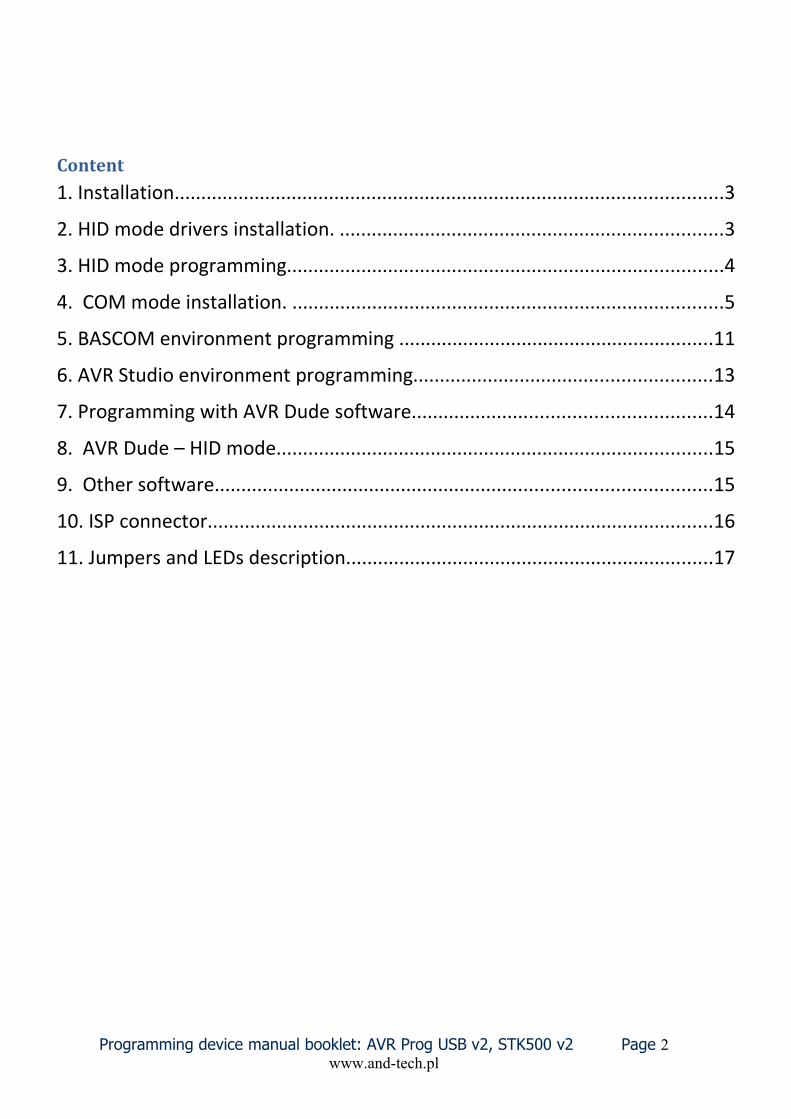
Content
1. Installation.......................................................................................................3
2. HID mode drivers installation. ........................................................................3
3. HID mode programming..................................................................................4
4. COM mode installation. .................................................................................5
5. BASCOM environment programming ...........................................................11
6. AVR Studio environment programming........................................................13
7. Programming with AVR Dude software........................................................14
8. AVR Dude – HID mode..................................................................................15
9. Other software.............................................................................................15
10. ISP connector...............................................................................................16
11. Jumpers and LEDs description.....................................................................17
Programming device manual booklet: AVR Prog USB v2, STK500 v2 Page 2www.and-tech.pl

1. InstallationThe programmer is connected to a computer using a USB A-B mini connection (most frequently used with digital cameras ). It is advised to use a cord not longer than 1.8m. A connection with the programmed set is conducted by a IDC-10 data tape. A connection with a programmed device performed by IDC-10 connectors on both ends. Programmer uses a set of pins Atmela standard compatible – to use it, take a one-one –one, non interlaced cable.
ATTENTION !!If, after a successful installation, a programmer is detected by Windows and lits a green LED, but
does not operate, connect the programmer to a PC/laptop excluding HUBs and docking station. In some specific situations, programmer’s functions may be interrupted by these devices.
2. HID mode drivers installation. To install a programmer as a HID device, place a jumper presented at the picture as JP3. Afterwards connect the programmer with a computer. The programmer will install its self automatically. It will take a few seconds. WARNING! Programmer installed as HID is commanded by a avrdude software.

3. HID mode programmingA programmer in the HID mode uses the Avrdude software. In order to obtain a better comfort of work is suggested to install a graphic Avrdude interface named GUI. Download GUI from our websit: http://www.and-tech.pl/avr-prog-usb-v2
In order to programme a processor, set the following fileds: Programmer and Port (see picture below). Choose a processor type in the Device field and a file to programme the processor in the Flash field. Start programming by pressing the Terminal button.

4. COM mode installation.
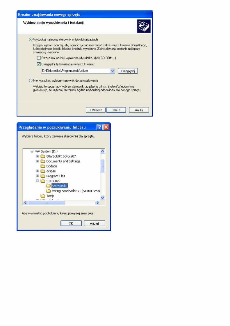
To install a programmer as a COM port, remove the jumper marked as JP3 (see picture below). Than connect the programmer with a computer and follow the below instructions.
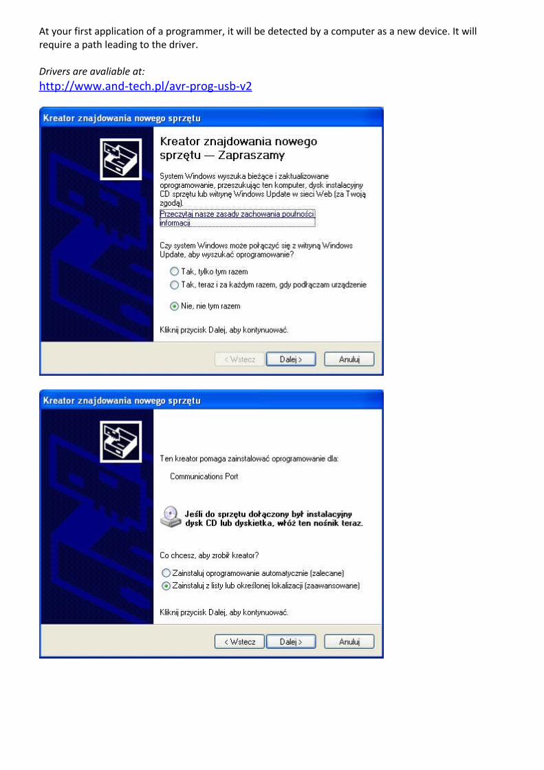
At your first application of a programmer, it will be detected by a computer as a new device. It will require a path leading to the driver.
Drivers are avaliable at:http://www.and-tech.pl/avr-prog-usb-v2
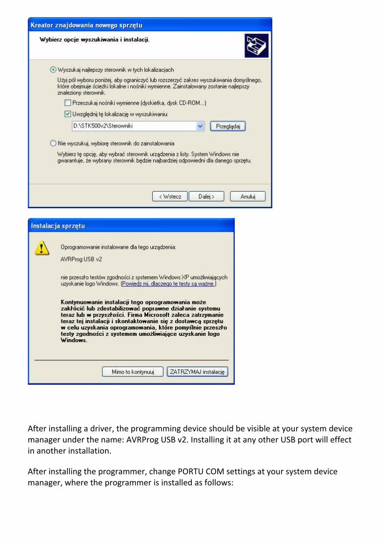
After installing a driver, the programming device should be visible at your system device manager under the name: AVRProg USB v2. Installing it at any other USB port will effect in another installation.
After installing the programmer, change PORTU COM settings at your system device manager, where the programmer is installed as follows:

If the programmer installs at a distant COM port (it is advised to install it between COM1 and COM9). See the below picture for more details.
In order to change the COM port, enter programmer’s advanced settings to choose a port between COM1 and COM9 (if these are already in use, try to relieve one and than check programmer’s correct operation).


5. BASCOM environment programming BASCOM’s configuration preparing for AVR Prog USB v2 supporting:
Choose a Programmer tab at Options menu:
Choose STK500 programmer and set it according to below orders: COM-port: serial COM with installed AVR Prog USB v2 (check Control Panel ->devices System-Manager -> COM i LPT ports), STK500 EXE: destination path to STK500 programmer (included in the set) Other settings – according to needs.

Now you can program microprocessor by click “Program chip” icon.

6. AVR Studio environment programming If there are no other programmers connected to the computer, click AVR icon (marked green). AVR Studio should detect the programmer its self automatically. If not, choose programmer type: STK500 and the port name where it is installed.
When a programmer is not detected by the software, the below window will appear on the screen, and the programmer has to be disconnected from a USB port and reconnected again, pressing the AVR icon. If this action will not provide programmer detection, check if the programmer type STK500 and AUTO have been chosen.

7. Programming with AVR Dude softwareIn order to programme a processor, set the Programmer field as on the below illustration. At the Port field, choose COM port where the programmer was installed (see page 8 of this booklet) and at the Device field choose the processor type you are using. Afterwards choose the file which will programme the microprocessor at the Flash field Start the programming by pressing Terminal button.

8. AVR Dude – HID mode
9. Other software AVR Prog USB v2 programmer is able to use any software capable of choosing STK500v2 programmer.

10. ISP connectorProgrammer equipped with a 10-pin ISP connection with KANADA standard. (see below for detailed signals description.

11. Jumpers and LEDs description
Programmer’s jumpers functions: JP1 – programmer’s programmed circuit power source (approx. 4.8V)
JP2 – Lowering work frequency of ISP, useful when a programmed microcontroller is clocked with 1MHz.
JP3 – HID mode
LED colours: Green – programmer connected to power source Red – programming
If a software error occurs after a zero signature is read by avrdude (Device signature = 0x000000), the reason might be the under-clocking or the programmed microcontroller large delay Install a jumper no.2 on the programmer to lower SPI speed when programming. The problem may concern unused microcontrollers (fusebits SUT set for Atmega8 provides major starting delay. The source of under-clocking is a 1MHz generator).


![Pololu - Pololu USB AVR Programmer User's Guide · PDF filePololu USB AVR Programmer User's Guide 1. ... avr_development_bundle_110524.exe?file_id=0J481] ... settings of your programmer](https://static.fdocuments.us/doc/165x107/5aad6b997f8b9a59658e4476/pololu-pololu-usb-avr-programmer-users-guide-usb-avr-programmer-users-guide.jpg)