AVR DAQ ADC - University of Florida · Atmel AVR Xmega Code using GPIO from the Atmel ASF for the...
10
University of Florida, EEL 5666: IMDL © Drs. Arroyo & Schwartz IMDL Software Series University of Florida, EEL-5666 © Drs. A. A. Arroyo & E. M. Schwartz 1 Atmel AVR Xmega Code using GPIO from the Atmel ASF for the ADC on DAQ Boards A. A. Arroyo IMDL Software Series University of Florida, EEL-5666 © Drs. A. A. Arroyo & E. M. Schwartz 2 ADC The Analog to Digital Converters (ADC) is used to sample and digitize analog signals. These devices are simple to communicate with and are quicker to set up than a USART. Typical Applications: – Audio Input – Checking battery voltage – Sensor - i.e., IR range finder XMega A1 devices have two ADCs. These two modules can be operated simultaneously, individually or synchronized. In the DAQ board they convert a 0 to 5v range into a 12-bit range (0 to 4095), about a ~.025% increment, e.g., 0 = 0v; 0xFFF=4095 ≈ 5v; 2047 ≈ 2.5v; 511 ≈ 0.625v, etc.
Transcript of AVR DAQ ADC - University of Florida · Atmel AVR Xmega Code using GPIO from the Atmel ASF for the...
University of Florida, EEL 5666: IMDL © Drs. Arroyo & Schwartz
IMDL Software Series
University of Florida, EEL-5666 © Drs. A. A. Arroyo & E. M. Schwartz
1
Atmel AVR Xmega Code using GPIO from the Atmel ASF
for the ADC on DAQ Boards
A. A. Arroyo
IMDL Software Series
University of Florida, EEL-5666 © Drs. A. A. Arroyo & E. M. Schwartz
2
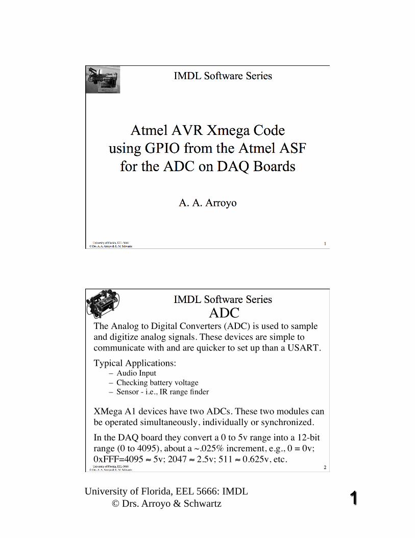
ADCThe Analog to Digital Converters (ADC) is used to sample and digitize analog signals. These devices are simple to communicate with and are quicker to set up than a USART. Typical Applications:
– Audio Input – Checking battery voltage – Sensor - i.e., IR range finder
XMega A1 devices have two ADCs. These two modules can be operated simultaneously, individually or synchronized.
In the DAQ board they convert a 0 to 5v range into a 12-bit range (0 to 4095), about a ~.025% increment, e.g., 0 = 0v; 0xFFF=4095 ≈ 5v; 2047 ≈ 2.5v; 511 ≈ 0.625v, etc.

University of Florida, EEL 5666: IMDL © Drs. Arroyo & Schwartz
IMDL Software Series
University of Florida, EEL-5666 © Drs. A. A. Arroyo & E. M. Schwartz
3
ADC
IMDL Software Series
University of Florida, EEL-5666 © Drs. A. A. Arroyo & E. M. Schwartz
4
ADC
University of Florida, EEL 5666: IMDL © Drs. Arroyo & Schwartz
IMDL Software Series
University of Florida, EEL-5666 © Drs. A. A. Arroyo & E. M. Schwartz
5
ADC
IMDL Software Series
University of Florida, EEL-5666 © Drs. A. A. Arroyo & E. M. Schwartz
6
ADC
University of Florida, EEL 5666: IMDL © Drs. Arroyo & Schwartz
IMDL Software Series
University of Florida, EEL-5666 © Drs. A. A. Arroyo & E. M. Schwartz
7
ADC
IMDL Software Series
University of Florida, EEL-5666 © Drs. A. A. Arroyo & E. M. Schwartz
8
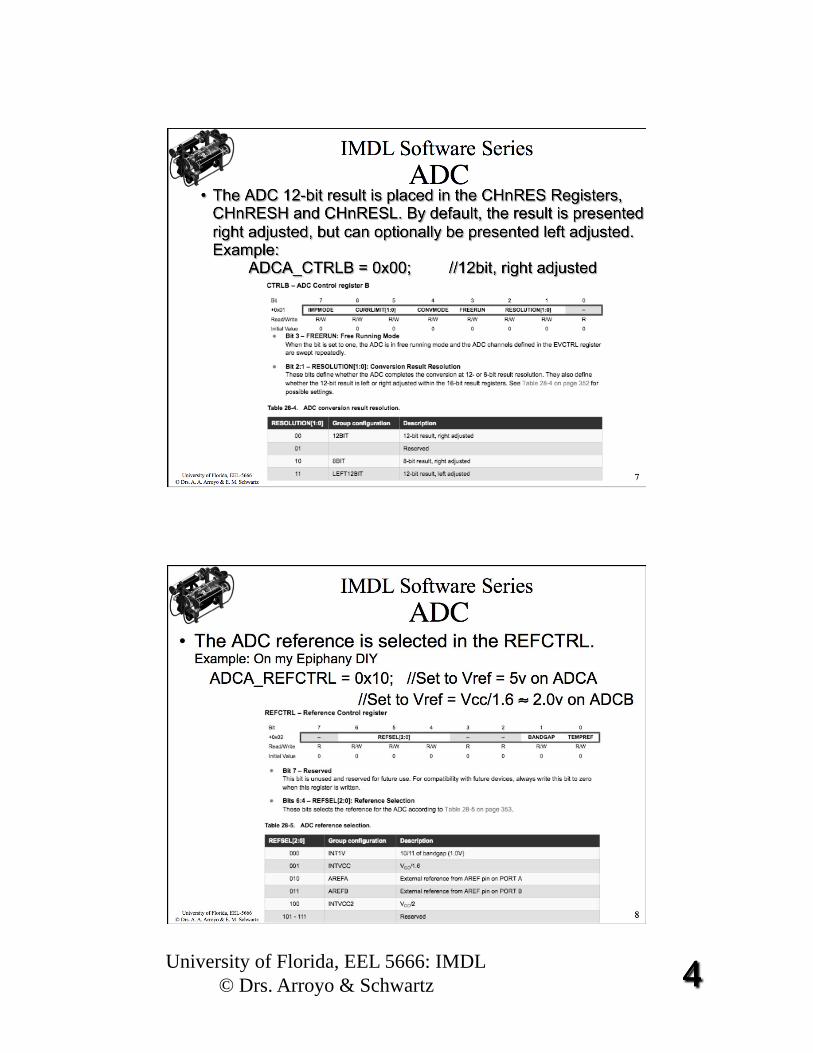
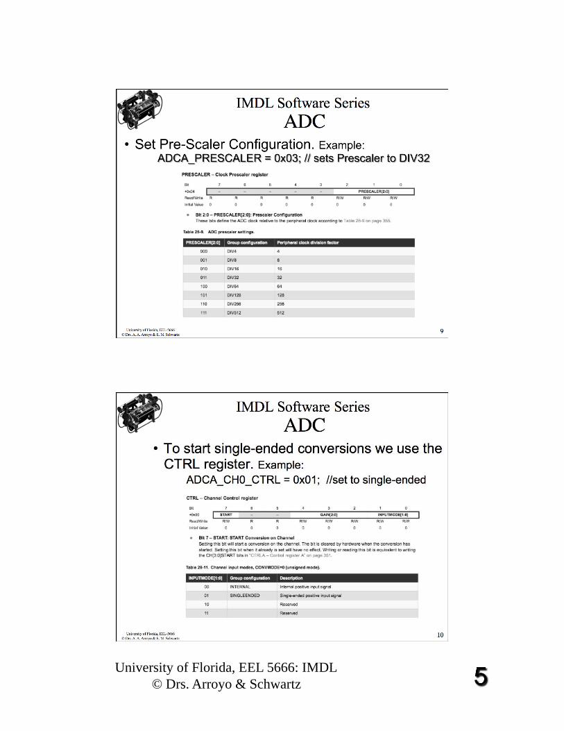
• The ADC reference is selected in the REFCTRL. Example: On my Epiphany DIY
ADCA_REFCTRL = 0x10; //Set to Vref = 5v on ADCA //Set to Vref = Vcc/1.6 ≈ 2.0v on ADCB
ADC
University of Florida, EEL 5666: IMDL © Drs. Arroyo & Schwartz
IMDL Software Series
University of Florida, EEL-5666 © Drs. A. A. Arroyo & E. M. Schwartz
9
ADC
IMDL Software Series
University of Florida, EEL-5666 © Drs. A. A. Arroyo & E. M. Schwartz
10
• To start single-ended conversions we use the CTRL register. Example:
ADCA_CH0_CTRL = 0x01; //set to single-ended
ADC
University of Florida, EEL 5666: IMDL © Drs. Arroyo & Schwartz
IMDL Software Series
University of Florida, EEL-5666 © Drs. A. A. Arroyo & E. M. Schwartz
11
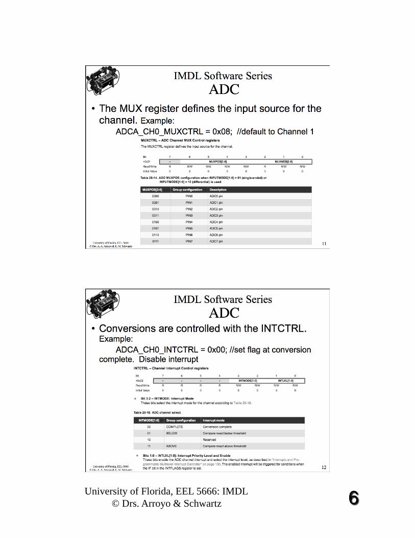
• The MUX register defines the input source for the channel. Example:
ADCA_CH0_MUXCTRL = 0x08; //default to Channel 1
ADC
IMDL Software Series
University of Florida, EEL-5666 © Drs. A. A. Arroyo & E. M. Schwartz
12
• Conversions are controlled with the INTCTRL. Example:
ADCA_CH0_INTCTRL = 0x00; //set flag at conversion complete. Disable interrupt
ADC
University of Florida, EEL 5666: IMDL © Drs. Arroyo & Schwartz
IMDL Software Series
University of Florida, EEL-5666 © Drs. A. A. Arroyo & E. M. Schwartz
13
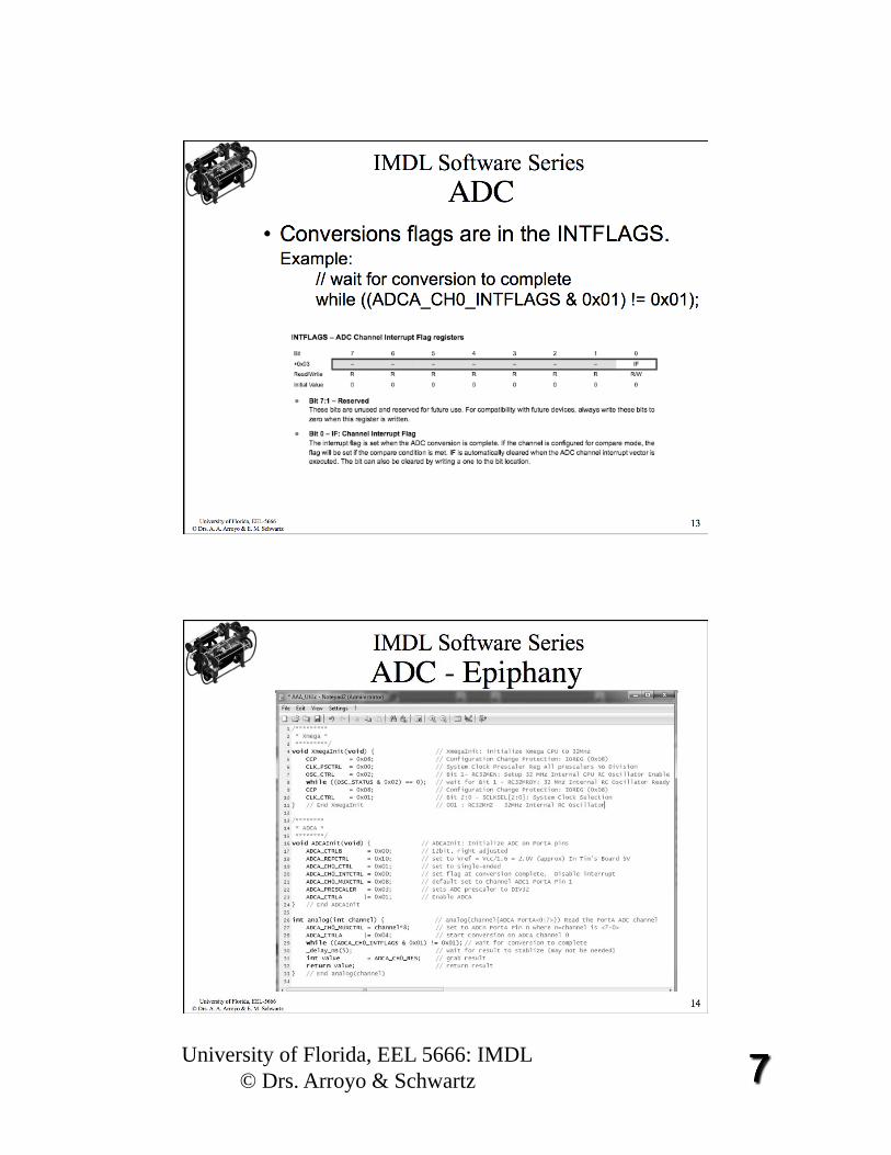
• Conversions flags are in the INTFLAGS. Example: // wait for conversion to complete while ((ADCA_CH0_INTFLAGS & 0x01) != 0x01);
ADC
IMDL Software Series
University of Florida, EEL-5666 © Drs. A. A. Arroyo & E. M. Schwartz
14
ADC - Epiphany
University of Florida, EEL 5666: IMDL © Drs. Arroyo & Schwartz
IMDL Software Series
University of Florida, EEL-5666 © Drs. A. A. Arroyo & E. M. Schwartz
15
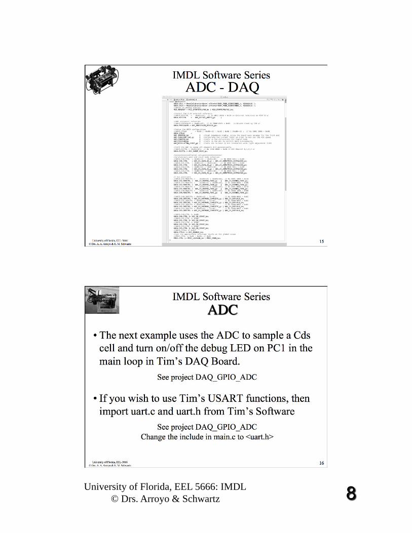
ADC - DAQ
IMDL Software Series
University of Florida, EEL-5666 © Drs. A. A. Arroyo & E. M. Schwartz
16
• The next example uses the ADC to sample a Cds cell and turn on/off the debug LED on PC1 in the main loop in Tim’s DAQ Board.
See project DAQ_GPIO_ADC
• If you wish to use Tim’s USART functions, then import uart.c and uart.h from Tim’s Software
See project DAQ_GPIO_ADC Change the include in main.c to <uart.h>
University of Florida, EEL 5666: IMDL © Drs. Arroyo & Schwartz
IMDL Software Series
University of Florida, EEL-5666 © Drs. A. A. Arroyo & E. M. Schwartz
17
Arduino ADC
• The example uses the ADC functions in the Arduino MEGA2560 Board to blink internal/external LEDs and uses the serial port to display data and control the LEDs after blinking the set a few times. Serial input j & k alternate the two external LEDs on pins 12 & 11 {on, off} and {off, on} respectively. Analog input A0 is connected to a Cds cell that controls the internal DBLED
• See Arduino Sketch: IMDL_ADC_Serial_External_LED
IMDL Software Series
University of Florida, EEL-5666 © Drs. A. A. Arroyo & E. M. Schwartz
18

University of Florida, EEL 5666: IMDL © Drs. Arroyo & Schwartz
IMDL Software Series
University of Florida, EEL-5666 © Drs. A. A. Arroyo & E. M. Schwartz
19
IMDL Software Series
University of Florida, EEL-5666 © Drs. A. A. Arroyo & E. M. Schwartz
20
The End!


![Atmel ATSHA204 - SparkFun Electronicscdn.sparkfun.com/.../Atmel-8740-CryptoAuth-ATSHA204-Datasheet.pdf · Atmel ATSHA204 [DATASHEET] 5 Atmel–8740E–CryptoAuth–ATSHA204–Datasheet–022013](https://static.fdocuments.us/doc/165x107/5e25fe64d9a5567efa4c5ccc/atmel-atsha204-sparkfun-atmel-atsha204-datasheet-5-atmela8740eacryptoauthaatsha204adatasheeta022013.jpg)