AVQ1022 RF Layer Monitoring Receiver Operational Manual
54
AVATEQ CORP. AVQ1022Rx Operational Manual AVQ1022Rx-OM Rev 1.4 Page 1 of 54 AVQ1022 RF Layer Monitoring Receiver Operational Manual (Product part #: AVQ1022xxxx) Document ID AVQ1022Rx-OM Rev Number 1.4 Rev Date 3/29/2018 3555 - 14th Ave.. Unit 18, Markham, ON L3R 0H5, Canada, Phone: (+1) 416-342-0761, Toll-free: 1-866-881-9388 Website: www.avateq.com
Transcript of AVQ1022 RF Layer Monitoring Receiver Operational Manual
AVATEQ CORP. AVQ1022Rx Operational Manual
AVQ1022Rx-OM Rev 1.4 Page 1 of 54
AVQ1022 RF Layer Monitoring Receiver Operational Manual (Product part #: AVQ1022xxxx)
Document ID AVQ1022Rx-OM Rev Number 1.4 Rev Date 3/29/2018
3555 - 14th Ave.. Unit 18, Markham, ON L3R 0H5, Canada, Phone: (+1) 416-342-0761, Toll-free: 1-866-881-9388
Website: www.avateq.com

AVATEQ CORP. AVQ1022Rx Operational Manual
AVQ1022Rx-OM Rev 1.4 Page 2 of 54
Revision History
Revision Date Author Comments
1.0 12/04/2017 VA Initial draft
1.1 01/23/2018 VA Section 3.1.4 (Emission mask) content changed
1.2 02/01/2018 VA Section 3.1.4 Further clarifications
1.3 03/23/2018 VA Relay Contact Current Ratings
1.4 03/29/2018 VA Screen shots updated, added a description of DAB/DAB+ Streaming Mods

AVATEQ CORP. AVQ1022Rx Operational Manual
AVQ1022Rx-OM Rev 1.4 Page 3 of 54
Table of Contents
1 Introduction to AVQ1022 product family............................................................................. 7
2 Description ............................................................................................................................ 8
2.1 Application ............................................................................................................. 8
2.2 External Interfaces and Indicators .......................................................................... 9
2.3 Functionality......................................................................................................... 11
3 Controls and Settings......................................................................................................... 12
3.1 AVQ1022 WEB UI................................................................................................ 12
3.1.1 Setting up network parameters ................................................................. 12
3.1.2 WEB User Interface (UI) ........................................................................... 14
3.1.3 Receiver Configuration ............................................................................. 15
3.1.4 Defining a pre-set Emission mask ............................................................. 16
3.1.5 Alarm Management .................................................................................. 17
3.1.6 Downloading Variation Log and SNMP MIB Files ..................................... 20
3.1.7 Backup and Restore Receiver Settings ..................................................... 21
3.1.8 NMS and SNMP User Settings ................................................................. 21
3.1.9 Setting Time ............................................................................................. 23
3.1.10 Resetting to Default Settings .................................................................... 23
3.1.11 Remote Upgrade ...................................................................................... 24
3.2 Broadcast Standard Licensing ............................................................................. 26
3.2.1 License upgrade ....................................................................................... 26
3.3 WEB GUI Special Features .................................................................................. 27
3.3.1 Plot Common Tools .................................................................................. 27
3.3.2 Echo Profile Variation Range Tool ............................................................ 29
3.3.3 Report....................................................................................................... 30
4 Broadcast standard specifics ............................................................................................ 31
4.1 ATSC 1.0 (A/53 and A/153) ................................................................................. 31
4.1.1 ATSC 1.0 Settings .................................................................................... 31
4.1.2 SFN Drift ................................................................................................... 32
4.1.3 ATSC Receiver Performance in the Presence of Echoes .......................... 32
4.1.4 ATSC 1.0 Statistics and Plots ................................................................... 33
4.2 ATSC 3.0 (A/322) ................................................................................................ 35
4.2.1 SFN Drift ................................................................................................... 36

AVATEQ CORP. AVQ1022Rx Operational Manual
AVQ1022Rx-OM Rev 1.4 Page 4 of 54
4.2.2 ATSC 3.0 Statistics and Plots ................................................................... 36
4.2.3 Channel Estimation Modes ....................................................................... 38
4.3 DTMB (GB20600-2006) ....................................................................................... 39
4.3.1 DTMB Receiver Settings........................................................................... 40
4.3.2 SFN Drift ................................................................................................... 41
4.3.3 DTMB Receiver Performance in the Presence of Echoes ......................... 41
4.3.4 DTMB Statistics ........................................................................................ 41
4.4 DAB/DAB+/T-DMB ............................................................................................... 42
4.4.1 DAB/DAB+/T-DMB Receiver settings ....................................................... 43
4.4.2 SFN Sync ................................................................................................. 43
4.4.3 SFN Drift ................................................................................................... 44
4.4.4 DAB/DAB+ Streaming Modes ................................................................... 44
4.5 DVB-S/S2/2x and DVB-CID ................................................................................. 50
4.5.1 DVB-S/S2/S2x Receiver Settings ............................................................. 51
4.5.2 DVB-S/S2 Statistics and Plots .................................................................. 51
5 Relay and Unit Reset DB9F Pin-out ................................................................................... 54
AVATEQ CORP. AVQ1022Rx Operational Manual
AVQ1022Rx-OM Rev 1.4 Page 5 of 54
List of Figures
Figure 1. Application Block-Diagram ...........................................................................................8
Figure 2. AVQ1022 and AVQ1022M Rear Panel Connectors ......................................................9
Figure 3. UI Main Page with Available Result and Navigation Controls: ....................................13
Figure 4. Login Page .................................................................................................................13
Figure 5. Network Settings ........................................................................................................14
Figure 6. Receiver Settings. An Example for ASTC 3.0 .............................................................15
Figure 7. Pre-set Emission Mask and Spectral Output ..............................................................16
Figure 8. Alarm Properties ........................................................................................................17
Figure 9. Alarm Thresholds .......................................................................................................18
Figure 10. Alarm and Variation Log Management .....................................................................19
Figure 11. Alarm Email Settings ................................................................................................19
Figure 12. Alarm Log.................................................................................................................20
Figure 13. Downloadable Files ..................................................................................................21
Figure 14. NMS User Management ...........................................................................................22
Figure 15. SNMP Management .................................................................................................22
Figure 16. Set Time...................................................................................................................23
Figure 17. Settings Backup and Restore ...................................................................................24
Figure 18. Stored Files and Uploads .........................................................................................25
Figure 19. Upgrade Completion ................................................................................................25
Figure 20. Licensed Standards .................................................................................................26
Figure 21. Plot Common Tools and Modes ...............................................................................27
Figure 22. Markers ....................................................................................................................28
Figure 23. Cross Bar Tool .........................................................................................................28
Figure 24. Manual Scale ...........................................................................................................29
Figure 25. CIR/Echo Plot Variation Range Tool ........................................................................29
Figure 26. ASTC 1.0 Settings ....................................................................................................32
Figure 27. ATSC 1.0 Signal Statistics .......................................................................................33
Figure 28. ATSC 1.0 Eye Diagram ............................................................................................34
Figure 29. ATSC 1.0 Constellation Diagrams ............................................................................34
Figure 30. ATSC 3.0 Statistics ..................................................................................................37
Figure 31. ATSC 3.0 Signaling ..................................................................................................38
Figure 32. ATSC 3.0 Channel Estimation Modes ......................................................................39
Figure 33. DTMB Specific Settings ............................................................................................40
AVATEQ CORP. AVQ1022Rx Operational Manual
AVQ1022Rx-OM Rev 1.4 Page 6 of 54
Figure 34. DTMB Statistics........................................................................................................42
Figure 35. DAB Receiver Settings .............................................................................................43
Figure 36. DAB SFN Pattern Sync ............................................................................................44
Figure 37. DAB/DAB+ Streaming Options .................................................................................45
Figure 38. DAB/DAB+ Ensemble and MSC Info ........................................................................46
Figure 39. DAB/DAB+ MUX and Service Selection ...................................................................47
Figure 40. VLC Media Player ....................................................................................................48
Figure 41. VLC Open Media Dialog ...........................................................................................49
Figure 42. DVB-S/S2/S2x Receiver Settings .............................................................................51
Figure 43. DVB-S/S2/S2x Spectrum with In-band DVB-CID Signal ...........................................52
Figure 44. Signal General and DVB-S/S2 Specific Statistics .....................................................52
Figure 45. DVB-CID Info ...........................................................................................................53
Figure 46. DVB-S2x Constellation .............................................................................................53

AVATEQ CORP. AVQ1022Rx Operational Manual
AVQ1022Rx-OM Rev 1.4 Page 7 of 54
1 Introduction to AVQ1022 product family In the context where broadcasters are concerned about providing the highest QoS with
extending coverage of the existing transmitters and, at the same time, reducing their network OPEX costs and limiting impact on the environment, Avateq Corp. introduces AVQ1022 RF Layer Monitoring Receiver as an extension of its product line. The new generation of the product is based on ActiveCore® Platform and addresses broadcasting industry today’s the most demanding needs for monitoring and diagnostic of:
transmitter system performance
transmitted signal quality
off-air signal quality on-channel and in-band interference SFN/Echo profile at a reception point AVQ1022 RF Layer Monitoring Receiver performs not only critical RF estimations of MER,
signal spectrum and emission mask providing early diagnostic of the signal possible degradation before any impairment is noticeable to the end Customer. The Receiver also provides indispensable tools to off-air applications including monitoring of SFN networks.
Avateq’s RF Layer Monitoring Receivers currently cover virtually all broadcasting industry standards. The list of supported by AVQ1022 standards includes:
ATSC/MH 1.0 ATSC 3.0 DAB/DAB+/T-DMB DTMB DVB-S/S2/2x DVB-CID DVB-T/H/T2 ISDB-T CMMB proprietary modulation schemes including hybrid “satellite-terrestrial” architectures. Primarily targeted to embedded applications the receiver has been designed as an easy-to-
use and cost-effective solution. It can be integrated into the transmitter system for remote monitoring applications or used as a stand alone unit during day-by-day operations, in-field and production tests.
Being integrated into a transmitter system the receiver can also be used as the transmitter site monitoring and controlling platform.
For more information about AVQ1022 RF Layer Monitoring Receiver product family please visit Avateq Corp. web site at www.avateq.com.

AVATEQ CORP. AVQ1022Rx Operational Manual
AVQ1022Rx-OM Rev 1.4 Page 8 of 54
2 Description
2.1 Application
The Monitoring Receiver is designed to perform continuous monitoring of the signal quality and report comprehensive set of critical parameters. The reported values can be used also for monitoring, diagnosing and troubleshooting transmitter system performance and QoS in the broadcast area.
The Receiver’s sophisticated Alarm Management System is designed and tuned to timely inform an operator about potential changes in signal quality and to perform preventive actions without the need for the operator’s immediate involvement.
The Receiver also provides a comprehensive set of plots allowing the operator to visually analyze monitored and estimated parameters.
All monitored parameters and available plots are automatically updated with user adjustable update rate.
Monitoring task can be executed continuously or once upon operator’s request depending on the Receiver scheduled operation.
Figure 1 presents the Receiver application block diagram.
Figure 1. Application Block-Diagram
The Receiver is mainly targeted to the following applications: a) monitoring signal quality at the transmitting site; b) monitoring signal quality at re-transmitting facilities; c) monitoring signal quality at a signal reception point. d) SFN/Echo profile monitoring Once set, the Receiver does not require user’s intervention for its day-by-day 24/7 operation. The Receiver is equipped with 2 RF inputs IN1 and IN2. Both inputs are identical and
switchable remotely through the Receiver User control Interface (UI). Although the signal could be supplied to both inputs simultaneously, the Receiver can access only one of them at a time. For example, in order to collect the most comprehensive set of parameters from a transmitter system, it is advised to connect the Receiver to the High Power Amplifier (HPA) output directly and the transmitter output band-path filter (BPF).

AVATEQ CORP. AVQ1022Rx Operational Manual
AVQ1022Rx-OM Rev 1.4 Page 9 of 54
Information and results from both inputs are presented on a common set of plots. Both inputs share the same alarm and data log resources, as well as input sensitivity and broadcast standard specific settings.
Though the receiver has an internal high-quality reference source, in order to obtain the most accurate estimations, an external, common to the transmitter system source of 10MHz, is preferable. The Receiver can be optionally equipped with an internal GPS/GLONASS receiver.
All necessary calculations, algorithmic support, controlling and data presentation functionality are done by the Receiver internally and do not require any additional external resources. All results, including plots, are presented on the Receiver WEB UI available through supporting [see 3.1 - AVQ1022 WEB UI] WEB browsing functionality devices including hand-helds and smartphones.
2.2 External Interfaces and Indicators
The Figure 2 below presents rear panel views for available AVQ1022 models: 1U Rack mounted AVQ1022 and Portable AVQ1022M devices.
Table 1 presents interfaces and connectors available on the Receiver rear panel. Please note that some interfaces and corresponding connectors are not available in AVQ1022M model of The Receiver.
Figure 2. AVQ1022 and AVQ1022M Rear Panel Connectors
Item #
Connector type
Name Comment
1, 2 N-type - F, 50 Ohm
RF IN1 / IN2 (optional) Two RF sampling ports for input signal
3 DB9-F Relay Port Please refer to Table 10 for DB9 Relay Port pin-out

AVATEQ CORP. AVQ1022Rx Operational Manual
AVQ1022Rx-OM Rev 1.4 Page 10 of 54
4 BNC - F, 50 Ohm
EXT REFERENCE, IN, 1PPS
Input for an external 1PPS signal synchronized with UTC
5 BNC - F, 50 Ohm
EXT REFERENCE, IN, 10 MHz
Input for an external 10 MHz reference source
6 BNC - F, 75 Ohm
ASI OUT DVB-ASI output, not used in all configurations of the Receiver
7 BNC - F, 75 Ohm
ASI IN DVB-ASI input, not used in all configurations of the Receiver
8 RJ45
Socket
Eth1 The Receiver main control and communication interface
9 RJ45 Socket Eth2 Stream interface, not used in all configurations
10 USB 2 – B DBG Debug console; Manufacturer / factory use only
11 USB 3 – B Host Host interface; not used in all configurations; available in avq1022 model only
12 SMA-F, 50Ohm
WiFi Ant The Receiver WiFi interface; not used in all configurations
13 T-type-F,
75Ohm
GPS Ant External active GPS antenna; not usedin all configurations
14 AC power Entry Power Supply 85-264V, 50..60Hz, AVQ1022 model
15 DC power Entry DC power supply 12DC, 3.3Amp, AVQ1022M model
Table 1. Rear panel connectors
In addition to the status reported on GUI, the Receiver operating conditions can be visually
monitored using its front panel LED indicators.
Item # Name Functionality
1 Power Green - Receiver is powered On
2 Status Green - Receiver current operational conditions and self test results are normal;
Red - an internal hardware error has been detected.
3 Alarm Green - no active alarms present;
Red - there is at least one active alarm.
The decision about an alarm event is made based on the Receiver alarm properties set through WEB control interface.
Table 2. Front Panel Indicators

AVATEQ CORP. AVQ1022Rx Operational Manual
AVQ1022Rx-OM Rev 1.4 Page 11 of 54
2.3 Functionality
In order to estimate signal quality and transmitter system performance, the Receiver calculates results on a sample of the signal. The signal samples are captured at regular intervals.
The Receiver internal source of 10MHz reference can be synchronized (locked) to an external 10MHz. The Receiver is programmed to automatically switch to the external source once it is detected at the designated input. UI indicates which source of the reference frequency is currently in use.
For UTC related measurements, for example, SFN shifts, the Receiver uses 1PPS signal which can be generated internally by the Receiver or provided from an external source. The internally generated 1PPS signal is obtained from two sources – an integrated GPS/GLONASS receiver if an antenna connected to “GPS Ant.” port or from an internal frequency source (a VCO) which is not synchronized with the UTC. Switching between 1PPS sources is done automatically. The external 1PPS source has the highest priority followed by the integrated GPS/GLONASS receiver.
All reported by the Receiver results can be conditionally divided into the following groups. First group is related to the signal general statistics. Reported parameters in this group include
input signal power level, signal PAPR, shoulder attenuation, signal central frequency offset, emission mask, etc.
Parameters of the second group include transmitter performance and channel characterization such as non-linear1 and linear distortions in a form of AM-AM/AM-PM curves, channel Frequency/Amplitude responses and Group Delay, amplitude and phase errors, etc.
Next group of the reported parameters is broadcast standard specific. The parameters include signal SNR/MER/EVM, framing structure, transmission modes, used modulation, guard interval length, etc.
Provided SFN/Echo Profile with “variation range” thresholds can be used for SFN monitoring applications. E-mail or SNMP trap notifications can be generated in case the profile has changed more than defined by the thresholds.
CCDF plots can be additionally used for transmitter system verification. Obtained results are compared against user defined thresholds. Alarms are triggered in case
of exceeding the thresholds values. Depending on alarm configuration the following actions can be undertaking:
- generating and sending an SNMP trap; - sending an email notification with site ID, time stamp and alarm type included in to the
message body;
- controlling the “Relay Port” contacts available on the Receiver rear panel.
1 please, refer to the standard specific section of the manual for the parameter availability

AVATEQ CORP. AVQ1022Rx Operational Manual
AVQ1022Rx-OM Rev 1.4 Page 12 of 54
3 Controls and Settings The Receiver can be fully configured and controlled though its WEB based UI which is
accessible from any WEB “browsing” enabled device including hand-held devices and smart phones.
The WEB UI is considered the default Interface responding to all needs of daily routine signal diagnostics.
3.1 AVQ1022 WEB UI
WEB GUI requires following WEB Browser versions: Mozilla Firefox version 20.0.1 or newer; OR
Microsoft Internet Explorer 9 or newer; OR
Google Chrome version 2.0.1410.64 or newer; OR
Safari version 5.1.7 or newer.
WEB GUI Requires Cookies are to be enabled. Using the Receiver WEB UI is a convenient way of operating the device thanks to interface
flexibility and availability on different platforms.
3.1.1 Setting up network parameters The default IP Address of the Receiver is 192.168.254.254. In order to communicate with the
device through a web browser, configure a computer to be on the same subnet as AVQ1022. This will allow you to have access to the Receiver Control Panel to tune network settings according to the required by your network parameters.
After setting network parameters of the computer/device running a WEB browser (Host) the following steps are recommended:
- verify basic communication between the Host and Receiver; you should be able to connect to the Receiver using the WEB browser by entering the Receiver IP address and see its WEB UI main page. Please refer to Figure 3 (1) below;
- make sure that the “Connection” bar is green and “Connected” status is present, Figure 3 (2);
- by pressing “Control Panel” (5) switch to the Receiver Control Panel Log-in page (Figure 4) and enter a password for Administrator level of access. The default password is “admin”;
- once logged-in, navigate to Control Panel->System->Network (Figure 5) and adjust the Receiver Network interface settings.
Note: In order the new settings take effect, the Receiver should be re-started. The preferable
way of the re-start is to set System Restart control to “On” (and press Update) on Control Panel->System->Restart System page of the Receiver WEB UI.

AVATEQ CORP. AVQ1022Rx Operational Manual
AVQ1022Rx-OM Rev 1.4 Page 13 of 54
Figure 3. UI Main Page with Available Result and Navigation Controls:
1 – The Receiver IP address; 2 – Connection status; 3 – Report Generation; 4 – Active Alarms; 5 – Control Panel; 6 – Available Plots and Statistics2; 7 - NTP Synchronization Status; 8 – Plot Tools
Figure 4. Login Page
2 Set of Available Plots and Statistics is standard dependable

AVATEQ CORP. AVQ1022Rx Operational Manual
AVQ1022Rx-OM Rev 1.4 Page 14 of 54
Figure 5. Network Settings
3.1.2 WEB User Interface (UI) The WEB UI consists of screens conveniently representing the monitored signal parameters
and plots. The Receiver Main (or default) WEB page layout is presented in Figure 3. Navigation between the UI pages is done by pressing icons from area 6, Figure 3, of the main
window providing an intuitive interface to all parameters and settings of the receiver. In order to connect to the Receiver and call the UI, a user should enter the Receiver IP address
to the WEB browser address bar. In order to set up parameters in the Control Panel and to eliminate unintentional changes
(specifically helpful while using hand-held devices), any manual interaction via WEB UI requires confirmation by pressing “Update” button on the page. The confirmation window pops up every time a parameter has been changed or set.
WEB GUI provides three levels of access to the Receiver: - "monitoring" level provides access to the Receiver basic monitoring functionality - reported
statuses, numeric results and plots; in order to operate the receiver at this level, no password is required;
- "operator" level provides an additional access to parameters which are responsible for alarm configuration and management through the device Control Panel; a default password for this level is "user";
- "administrator" level gives full control over the Receiver settings, alarm management functionality and remote upgrade are accessible; a default password is "admin".
Both passwords can be changed from Administrator level through Control Panel -> System -> Access Settings.
Please refer to 3.1.1 on how to access the Control Panel.
AVATEQ CORP. AVQ1022Rx Operational Manual
AVQ1022Rx-OM Rev 1.4 Page 15 of 54
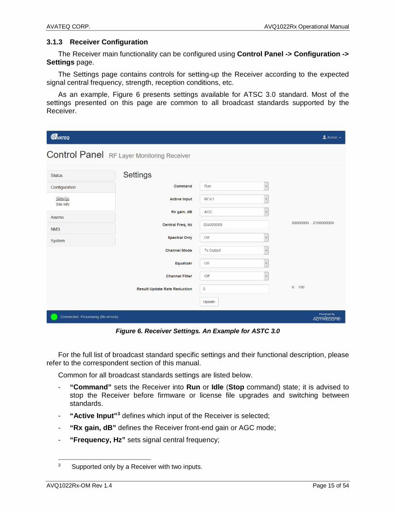
3.1.3 Receiver Configuration The Receiver main functionality can be configured using Control Panel -> Configuration ->
Settings page. The Settings page contains controls for setting-up the Receiver according to the expected
signal central frequency, strength, reception conditions, etc. As an example, Figure 6 presents settings available for ATSC 3.0 standard. Most of the
settings presented on this page are common to all broadcast standards supported by the Receiver.
Figure 6. Receiver Settings. An Example for ASTC 3.0
For the full list of broadcast standard specific settings and their functional description, please
refer to the correspondent section of this manual. Common for all broadcast standards settings are listed below. - “Command” sets the Receiver into Run or Idle (Stop command) state; it is advised to
stop the Receiver before firmware or license file upgrades and switching between standards.
- “Active Input”3 defines which input of the Receiver is selected; - “Rx gain, dB” defines the Receiver front-end gain or AGC mode; - “Frequency, Hz” sets signal central frequency;
3 Supported only by a Receiver with two inputs.
AVATEQ CORP. AVQ1022Rx Operational Manual
AVQ1022Rx-OM Rev 1.4 Page 16 of 54
- “Spectral Only”; only spectral parameters and plots are calculated and displayed; - “Channel Mode” defines channel estimation modes; it is recommended to use TX out
mode when the Receiver samples signal directly from a transmitter system input or when there is no SFN/Multipath environment; use Off-Air option if working in SFN environment with multiple echoes.
- “Equalizer” switches On/Off the Receiver internal equalizer; - “Channel Filter” switches On/Off the Receiver channel filter; the channel filter bandwidth
is standard dependable; - “Result Update Rate Reduction” allows reducing the Receiver result update rate in
proportion to the entered value; for example, setting n means that the results will be updated with n times reduced rate; this option allows reducing load to the network link between the Receiver and Host.
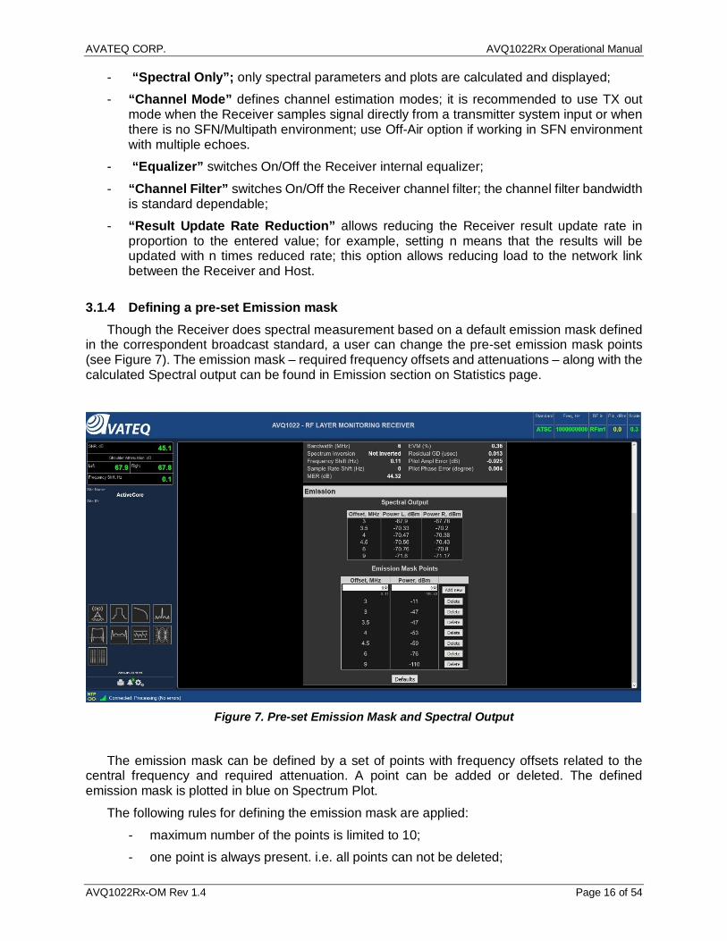
3.1.4 Defining a pre-set Emission mask Though the Receiver does spectral measurement based on a default emission mask defined
in the correspondent broadcast standard, a user can change the pre-set emission mask points (see Figure 7). The emission mask – required frequency offsets and attenuations – along with the calculated Spectral output can be found in Emission section on Statistics page.
Figure 7. Pre-set Emission Mask and Spectral Output
The emission mask can be defined by a set of points with frequency offsets related to the
central frequency and required attenuation. A point can be added or deleted. The defined emission mask is plotted in blue on Spectrum Plot.
The following rules for defining the emission mask are applied: - maximum number of the points is limited to 10; - one point is always present. i.e. all points can not be deleted;
AVATEQ CORP. AVQ1022Rx Operational Manual
AVQ1022Rx-OM Rev 1.4 Page 17 of 54
- a second point with equal to already present offset and attenuation values can not be added, i.e. no duplicates are allowed.
Resolution bandwidth, used for calculation of the emission, is predefined and selected according to the broadcast standard requirements.
If the Receiver supports multiple standards the user defined emission mask is reset to default upon changing the standard.
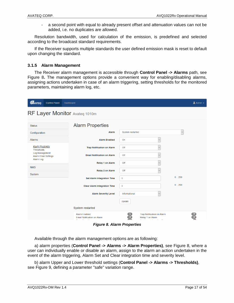
3.1.5 Alarm Management The Receiver alarm management is accessible through Control Panel -> Alarms path, see
Figure 8. The management options provide a convenient way for enabling/disabling alarms, assigning actions undertaken in case of an alarm triggering, setting thresholds for the monitored parameters, maintaining alarm log, etc.
Figure 8. Alarm Properties
Available through the alarm management options are as following: a) alarm properties (Control Panel -> Alarms -> Alarm Properties), see Figure 8, where a
user can individually enable or disable an alarm, assign to the alarm an action undertaken in the event of the alarm triggering, Alarm Set and Clear integration time and severity level.
b) alarm Upper and Lower threshold settings (Control Panel -> Alarms -> Thresholds), see Figure 9, defining a parameter "safe" variation range.

AVATEQ CORP. AVQ1022Rx Operational Manual
AVQ1022Rx-OM Rev 1.4 Page 18 of 54
Figure 9. Alarm Thresholds
c) Alarm Log File Properties (Alarms -> Log Management), see Figure 10 two functional set
of controls are related to the alarm log and parameter variation log files. The first set allows changing the Alarm Log display properties and clearing/resetting the log file. The second set controls Parameter Variation Log File allowing adjusting data storing periodicity and clearing/resetting the File.

AVATEQ CORP. AVQ1022Rx Operational Manual
AVQ1022Rx-OM Rev 1.4 Page 19 of 54
Figure 10. Alarm and Variation Log Management
d) e-mail notification settings (Alarms -> Alarm Email Settings), see Figure 11. Please,
consult your network administrator for proper server settings.
Figure 11. Alarm Email Settings
e) alarm log and a list of currently active alarms (Alarms -> Alarm Log)

AVATEQ CORP. AVQ1022Rx Operational Manual
AVQ1022Rx-OM Rev 1.4 Page 20 of 54
Figure 12. Alarm Log
3.1.6 Downloading Variation Log and SNMP MIB Files Two files are available for downloading from the Receiver. They are Parameter Variation Log
file containing time stamped records with measured values and SNMP MIB file. Figure 13. Downloadable Files below shows the files and access path to the downloading controls.
The Receiver provides an automated log recording feature accessible through Alarms -> Log Management (see Figure 10).

AVATEQ CORP. AVQ1022Rx Operational Manual
AVQ1022Rx-OM Rev 1.4 Page 21 of 54
Figure 13. Downloadable Files
Parameter Variation Log records are created only while the Receiver's current command is
“RUN” (3.1.3). The Log file is stored in the Receiver internal non-volatile memory as a comma separated text file (CSV). It is available for downloading from the Downloads menu (see Figure 13. Downloadable Files).
3.1.7 Backup and Restore Receiver Settings The complete set of the Receiver current settings can be backed up and restored using a
menu available from Control Panel -> System -> Settings Backup & Restore.
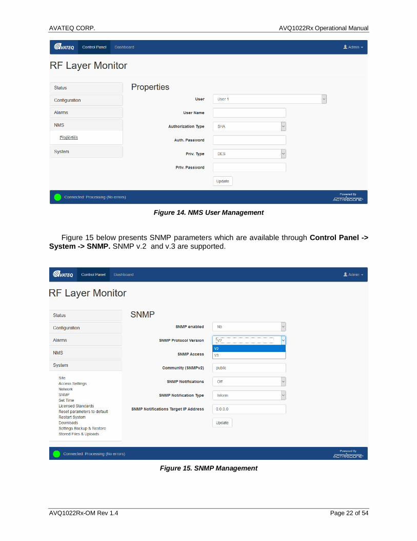
3.1.8 NMS and SNMP User Settings NMS settings are accessible through NMS Control Panel -> NMS -> Properties, see Figure
14.
AVATEQ CORP. AVQ1022Rx Operational Manual
AVQ1022Rx-OM Rev 1.4 Page 22 of 54
Figure 14. NMS User Management
Figure 15 below presents SNMP parameters which are available through Control Panel ->
System -> SNMP. SNMP v.2 and v.3 are supported.
Figure 15. SNMP Management
AVATEQ CORP. AVQ1022Rx Operational Manual
AVQ1022Rx-OM Rev 1.4 Page 23 of 54
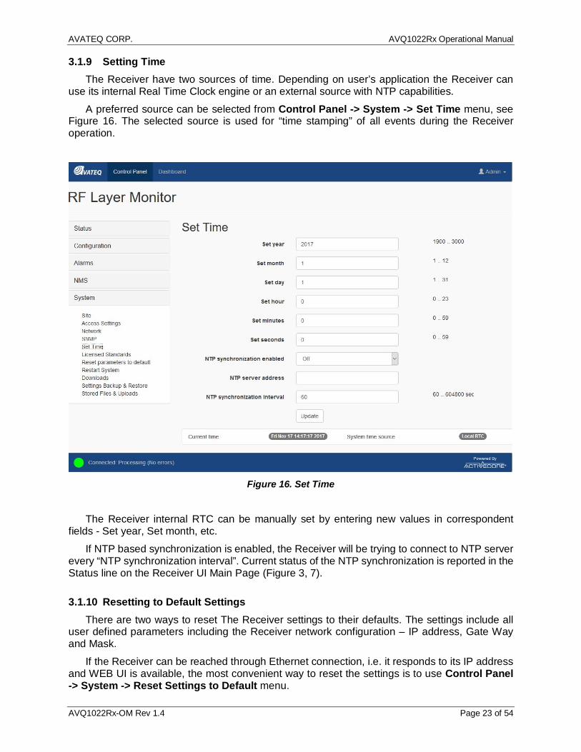
3.1.9 Setting Time The Receiver have two sources of time. Depending on user’s application the Receiver can
use its internal Real Time Clock engine or an external source with NTP capabilities. A preferred source can be selected from Control Panel -> System -> Set Time menu, see
Figure 16. The selected source is used for “time stamping” of all events during the Receiver operation.
Figure 16. Set Time
The Receiver internal RTC can be manually set by entering new values in correspondent
fields - Set year, Set month, etc. If NTP based synchronization is enabled, the Receiver will be trying to connect to NTP server
every “NTP synchronization interval”. Current status of the NTP synchronization is reported in the Status line on the Receiver UI Main Page (Figure 3, 7).
3.1.10 Resetting to Default Settings There are two ways to reset The Receiver settings to their defaults. The settings include all
user defined parameters including the Receiver network configuration – IP address, Gate Way and Mask.
If the Receiver can be reached through Ethernet connection, i.e. it responds to its IP address and WEB UI is available, the most convenient way to reset the settings is to use Control Panel -> System -> Reset Settings to Default menu.

AVATEQ CORP. AVQ1022Rx Operational Manual
AVQ1022Rx-OM Rev 1.4 Page 24 of 54
In the situation when there is no access to the unit through Ethernet (for example, if the Receiver IP address is lost or unknown) a hardware-based reset can be performed. For the hardware Reset pins 2 and 3 of the “Relay” DB9 connector (the unit rear panel) should be shortened for 10 seconds with the following power cycling of the unit.
The hardware Reset step by step procedure is: - Power up the unit; - Wait for approximately 60 seconds until the unit fully booted; - Make short pins 2 and 3 of the Relay DB9 connector located on the unit rear panel; - Wait for 10 seconds; - Release the pins; - Power cycle the unit. The default settings are now in effect.
3.1.11 Remote Upgrade The Receiver can be remotely upgraded using Control Panel -> System -> Stored Files &
Uploads menu. It is recommended to save the Receiver current settings (Figure 17) before upgrading the unit.
Figure 17. Settings Backup and Restore
The Receiver configuration can be restored at any time by uploading its previously stored
settings. The Receiver remote upgrade procedure includes the following steps: 1. Navigate to the Stored Files & Uploads menu page (Figure 18).

AVATEQ CORP. AVQ1022Rx Operational Manual
AVQ1022Rx-OM Rev 1.4 Page 25 of 54
Figure 18. Stored Files and Uploads
2. Click Browse to locate an upgrade image file (*.img). 3. Click “Upload” to initiate file transfer and system upgrade sequence. 4. Wait for the upgrade completion notification and a prompt to restart the unit (Figure 19).
Figure 19. Upgrade Completion
AVATEQ CORP. AVQ1022Rx Operational Manual
AVQ1022Rx-OM Rev 1.4 Page 26 of 54
Note: The first start-up of the unit after upgrade takes a bit longer since the upgrade image consistency is being verified. The system automatically rolls back to the previous image in case of any issues with the newly downloaded image are discovered.
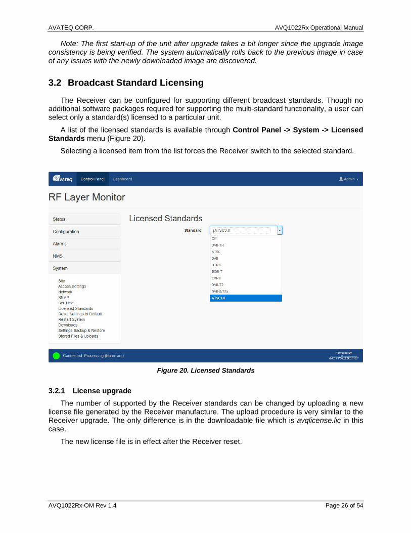
3.2 Broadcast Standard Licensing
The Receiver can be configured for supporting different broadcast standards. Though no additional software packages required for supporting the multi-standard functionality, a user can select only a standard(s) licensed to a particular unit.
A list of the licensed standards is available through Control Panel -> System -> Licensed Standards menu (Figure 20).
Selecting a licensed item from the list forces the Receiver switch to the selected standard.
Figure 20. Licensed Standards
3.2.1 License upgrade The number of supported by the Receiver standards can be changed by uploading a new
license file generated by the Receiver manufacture. The upload procedure is very similar to the Receiver upgrade. The only difference is in the downloadable file which is avqlicense.lic in this case.
The new license file is in effect after the Receiver reset.

AVATEQ CORP. AVQ1022Rx Operational Manual
AVQ1022Rx-OM Rev 1.4 Page 27 of 54
3.3 WEB GUI Special Features
3.3.1 Plot Common Tools A set of Tools available for a plot can be opened by Tools icon in the upper right corner of the
plotting area. Please refer to Figure 3, item 8. The available set of tools might differ for different plots providing the most convenient way for
working with a particular plot. There are two controls available from the Tools menu. The controls are Autoscale and Mode.
By default, all plots use Autoscale. The plot is automatically scaled on X and Y axes in order to maximize the plotting area. In Autoscale no additional plot Modes can be selected.
In order to access different Modes, the Autoscale control should be switched Off. Figure 21 below presents Modes Plot area tools when Autoscale is Off.
Figure 21. Plot Common Tools and Modes
- “Normal” mode can be used if no auto scaling is required; - “Markers” tool allows conveniently setting several markers on the plot, see Figure 22.
Marker position can be individually adjusted using “Edit” icon in the Marker table.

AVATEQ CORP. AVQ1022Rx Operational Manual
AVQ1022Rx-OM Rev 1.4 Page 28 of 54
Figure 22. Markers
- “Cross bar” tool is useful for a quick relative measurement between any two points of the
plot, see Figure 23.
Figure 23. Cross Bar Tool
- “Manual Scale” tool is a convenient way for adjusting Min/Max and Step (unit per division) values for a plot. See Figure 24.
AVATEQ CORP. AVQ1022Rx Operational Manual
AVQ1022Rx-OM Rev 1.4 Page 29 of 54
Figure 24. Manual Scale
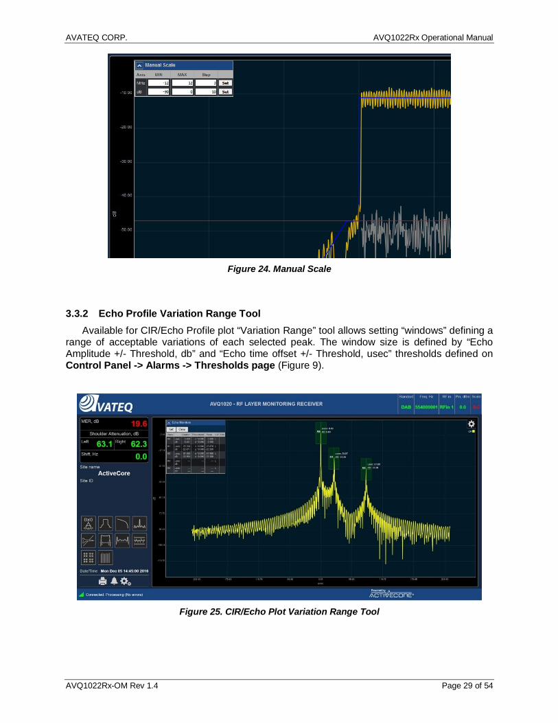
3.3.2 Echo Profile Variation Range Tool Available for CIR/Echo Profile plot “Variation Range” tool allows setting “windows” defining a
range of acceptable variations of each selected peak. The window size is defined by “Echo Amplitude +/- Threshold, db” and “Echo time offset +/- Threshold, usec” thresholds defined on Control Panel -> Alarms -> Thresholds page (Figure 9).
Figure 25. CIR/Echo Plot Variation Range Tool

AVATEQ CORP. AVQ1022Rx Operational Manual
AVQ1022Rx-OM Rev 1.4 Page 30 of 54
3.3.3 Report By pressing Report Icon on the Receiver WEB Main page (Figure 3, item 3) a "snapshot" report can be generated and stored on a local machine. The report contains all numerical data and plots and can be used for further analysis or troubleshooting.

AVATEQ CORP. AVQ1022Rx Operational Manual
AVQ1022Rx-OM Rev 1.4 Page 31 of 54
4 Broadcast standard specifics
4.1 ATSC 1.0 (A/53 and A/153)
A member of ActiveCore® AVQ1022 product family, AVQ1022ATSC is an RF layer Monitoring Receiver and Signal Analyzer for A/53 and A/153 ATSC Digital Television Standards.
Table below presents a list of available plots and monitored parameters.
General Signal Parameters:
- Signal PAPR, dB - Signal Power, dBm
General Spectral Parameters:
- Shoulder Attenuation, dB (According to FCC requirements) - Bandwidth, MHz - Frequency Offset, Hz - Sampling Rate Shift, Hz
ATSC A/53 and A/153 specific parameters:
- MER, dB - EVM, % - SNR, dB - Pilot amplitude error, dB - Pilot phase error, degree - Amplitude (AM-AM), dB and Phase (AM-PM) error, degree - Output signal Group Delay, micro seconds - Signal Inversion - Channel Emission Mask according to FCC requirements
Available Plots: - Spectrum and in-band interference - Eye / Level Diagram - Non-Linear - HPA AM-AM, AM-PM - Group Delay, Frequency and Amplitude Response - CIR/Echo Profile Plot - CCDF Plot - Channel Frequency Response - Event History and Alarm log - History of Shoulder Attenuation / Group
Delay/MER/SNR/PAPR variation - Transmitter SFN Drift
Table 3. Monitored Parameters and Plots – ATSC1.0
The list of monitored parameters, available plots and alarm events are constantly reviewed
and extended. Please refer to the product data sheet for the most updated information.
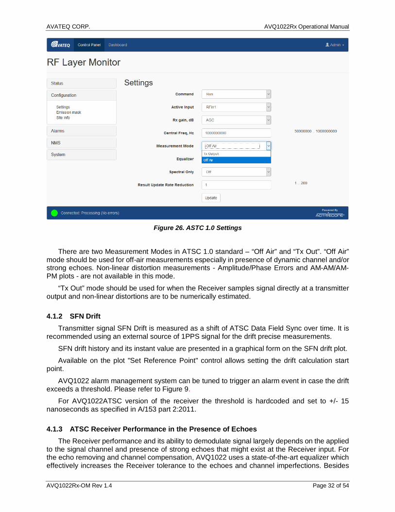
4.1.1 ATSC 1.0 Settings Settings available for ATSC 1.0 standard is presented in Figure 26. ASTC 1.0 Settings.
AVATEQ CORP. AVQ1022Rx Operational Manual
AVQ1022Rx-OM Rev 1.4 Page 32 of 54
Figure 26. ASTC 1.0 Settings
There are two Measurement Modes in ATSC 1.0 standard – “Off Air” and “Tx Out”. “Off Air”
mode should be used for off-air measurements especially in presence of dynamic channel and/or strong echoes. Non-linear distortion measurements - Amplitude/Phase Errors and AM-AM/AM-PM plots - are not available in this mode.
“Tx Out” mode should be used for when the Receiver samples signal directly at a transmitter output and non-linear distortions are to be numerically estimated.
4.1.2 SFN Drift Transmitter signal SFN Drift is measured as a shift of ATSC Data Field Sync over time. It is
recommended using an external source of 1PPS signal for the drift precise measurements. SFN drift history and its instant value are presented in a graphical form on the SFN drift plot. Available on the plot "Set Reference Point" control allows setting the drift calculation start
point. AVQ1022 alarm management system can be tuned to trigger an alarm event in case the drift
exceeds a threshold. Please refer to Figure 9. For AVQ1022ATSC version of the receiver the threshold is hardcoded and set to +/- 15
nanoseconds as specified in A/153 part 2:2011.
4.1.3 ATSC Receiver Performance in the Presence of Echoes The Receiver performance and its ability to demodulate signal largely depends on the applied
to the signal channel and presence of strong echoes that might exist at the Receiver input. For the echo removing and channel compensation, AVQ1022 uses a state-of-the-art equalizer which effectively increases the Receiver tolerance to the echoes and channel imperfections. Besides
AVATEQ CORP. AVQ1022Rx Operational Manual
AVQ1022Rx-OM Rev 1.4 Page 33 of 54
other factors the equalizer performance depends on number of filter taps used in the equalizer, i.e. "equalizer length", that, in its turn, can affect processing time and the Receiver parameter update rate.
Though the "longer" equalizer allows removing stronger echoes in a wider delay range, it is recommended setting "Equalizer" control On only when it is really necessary.
The AVQ1022 ATSC Receiver implements an equalizer capable of removing pre- and post echoes in a wide range of amplitudes and delays. Table 4. Echo Cancelling Performance below defines the equalizer performance in terms of the echo level and time distance related to the main signal lobe.
Echo relative amplitude, db Delay, microseconds,
Echo canceller Off / On Remaining echo relative amplitude, dB
-15 ±4 / ±11.8 > - 25..-30
-10 ±1.86 / ±5.6 > - 25..-30
-5 ±0.6 / ±2.04 > - 25..-30
Table 4. Echo Cancelling Performance
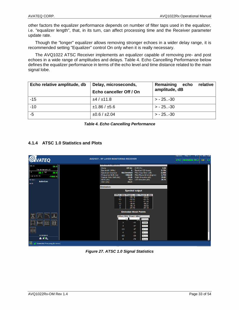
4.1.4 ATSC 1.0 Statistics and Plots
Figure 27. ATSC 1.0 Signal Statistics

AVATEQ CORP. AVQ1022Rx Operational Manual
AVQ1022Rx-OM Rev 1.4 Page 34 of 54
Figure 28. ATSC 1.0 Eye Diagram
Figure 29. ATSC 1.0 Constellation Diagrams
AVATEQ CORP. AVQ1022Rx Operational Manual
AVQ1022Rx-OM Rev 1.4 Page 35 of 54
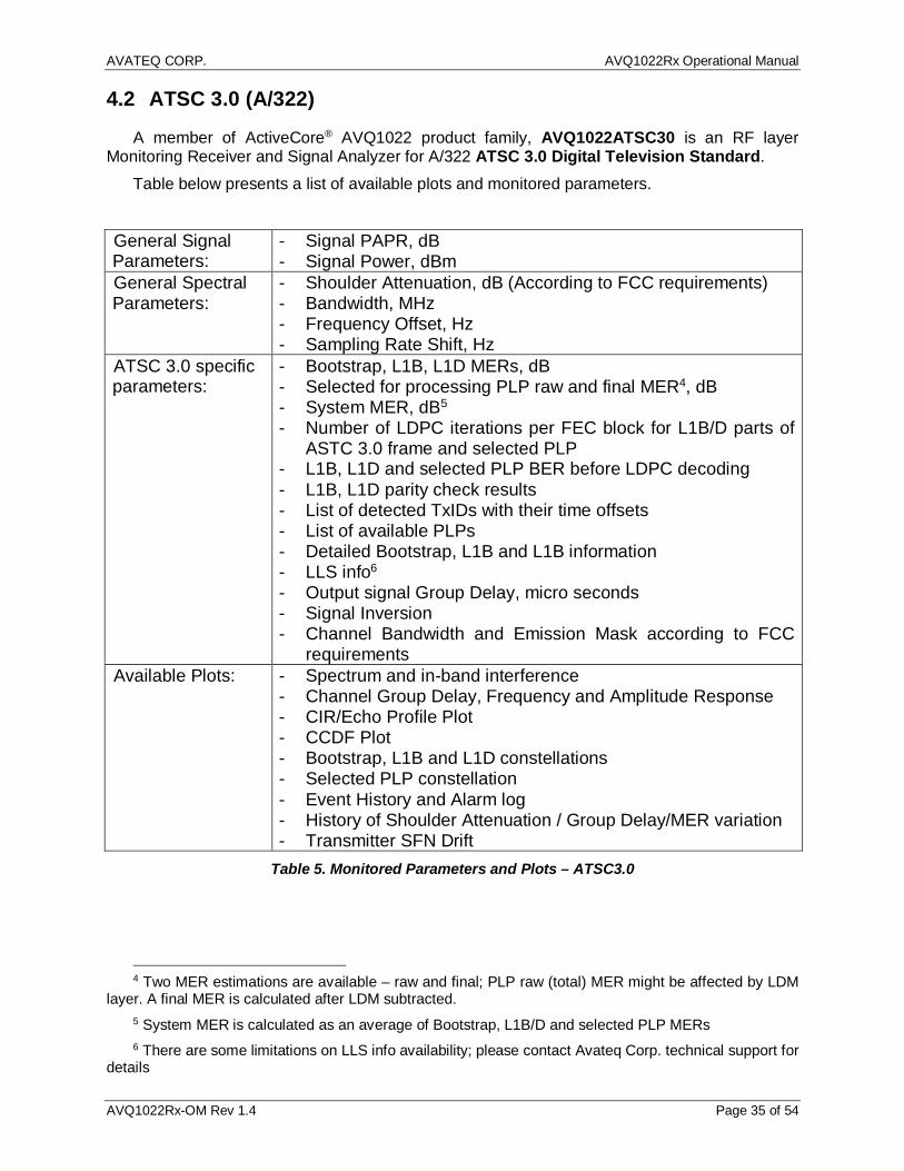
4.2 ATSC 3.0 (A/322)
A member of ActiveCore® AVQ1022 product family, AVQ1022ATSC30 is an RF layer Monitoring Receiver and Signal Analyzer for A/322 ATSC 3.0 Digital Television Standard.
Table below presents a list of available plots and monitored parameters.
General Signal Parameters:
- Signal PAPR, dB - Signal Power, dBm
General Spectral Parameters:
- Shoulder Attenuation, dB (According to FCC requirements) - Bandwidth, MHz - Frequency Offset, Hz - Sampling Rate Shift, Hz
ATSC 3.0 specific parameters:
- Bootstrap, L1B, L1D MERs, dB - Selected for processing PLP raw and final MER4, dB - System MER, dB5 - Number of LDPC iterations per FEC block for L1B/D parts of
ASTC 3.0 frame and selected PLP - L1B, L1D and selected PLP BER before LDPC decoding - L1B, L1D parity check results - List of detected TxIDs with their time offsets - List of available PLPs - Detailed Bootstrap, L1B and L1B information - LLS info6 - Output signal Group Delay, micro seconds - Signal Inversion - Channel Bandwidth and Emission Mask according to FCC
requirements Available Plots: - Spectrum and in-band interference
- Channel Group Delay, Frequency and Amplitude Response - CIR/Echo Profile Plot - CCDF Plot - Bootstrap, L1B and L1D constellations - Selected PLP constellation - Event History and Alarm log - History of Shoulder Attenuation / Group Delay/MER variation - Transmitter SFN Drift
Table 5. Monitored Parameters and Plots – ATSC3.0
4 Two MER estimations are available – raw and final; PLP raw (total) MER might be affected by LDM
layer. A final MER is calculated after LDM subtracted. 5 System MER is calculated as an average of Bootstrap, L1B/D and selected PLP MERs 6 There are some limitations on LLS info availability; please contact Avateq Corp. technical support for
details
AVATEQ CORP. AVQ1022Rx Operational Manual
AVQ1022Rx-OM Rev 1.4 Page 36 of 54
4.2.1 SFN Drift Transmitter signal SFN Drift is measured as a shift of ATSC 3.0 Bootstrap over time. It is
recommended using an external source of 1PPS signal for the drift precise measurements. SFN drift history and its instant value are presented in a graphical form on the SFN drift plot. Available on the plot "Set Reference Point" control allows setting the drift calculation start
point. AVQ1022 alarm management system can be tuned to trigger an alarm event in case the drift
exceeds +/- GI.
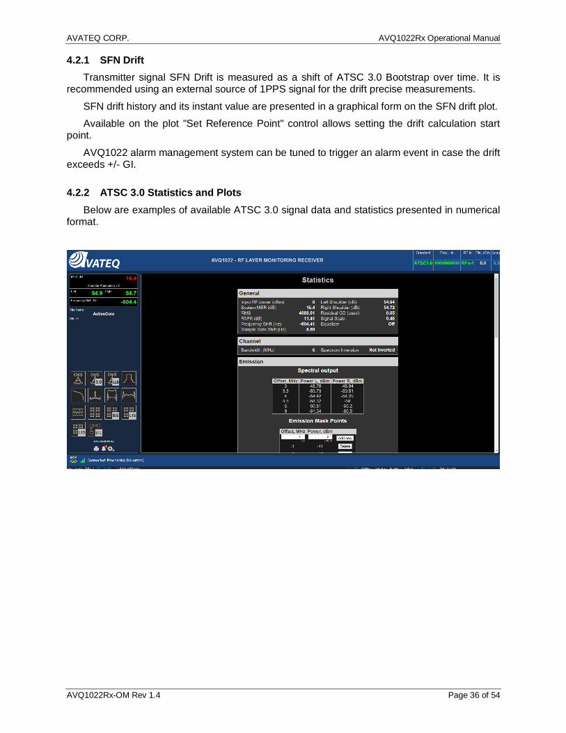
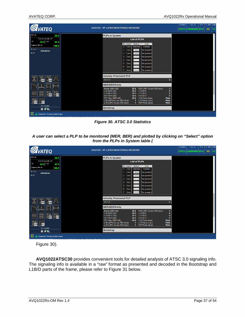
4.2.2 ATSC 3.0 Statistics and Plots Below are examples of available ATSC 3.0 signal data and statistics presented in numerical
format.
AVATEQ CORP. AVQ1022Rx Operational Manual
AVQ1022Rx-OM Rev 1.4 Page 37 of 54
Figure 30. ATSC 3.0 Statistics
A user can select a PLP to be monitored (MER, BER) and plotted by clicking on “Select” option
from the PLPs in System table (
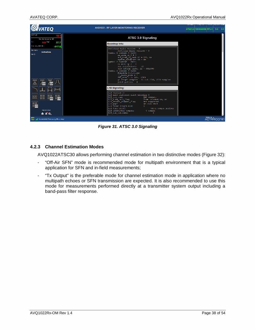
Figure 30). AVQ1022ATSC30 provides convenient tools for detailed analysis of ATSC 3.0 signaling info.
The signaling info is available in a “raw” format as presented and decoded in the Bootstrap and L1B/D parts of the frame, please refer to Figure 31 below.
AVATEQ CORP. AVQ1022Rx Operational Manual
AVQ1022Rx-OM Rev 1.4 Page 38 of 54
Figure 31. ATSC 3.0 Signaling
4.2.3 Channel Estimation Modes AVQ1022ATSC30 allows performing channel estimation in two distinctive modes (Figure 32): - “Off-Air SFN” mode is recommended mode for multipath environment that is a typical
application for SFN and in-field measurements; - “Tx Output” is the preferable mode for channel estimation mode in application where no
multipath echoes or SFN transmission are expected. It is also recommended to use this mode for measurements performed directly at a transmitter system output including a band-pass filter response.

AVATEQ CORP. AVQ1022Rx Operational Manual
AVQ1022Rx-OM Rev 1.4 Page 39 of 54
Figure 32. ATSC 3.0 Channel Estimation Modes
4.3 DTMB (GB20600-2006)
A member of ActiveCore® AVQ1020 product family, AVQ1020DTMB is an RF layer Monitoring Receiver and Signal Analyzer for GB20600-2006 compliant Digital Television Terrestrial Broadcasting System.
Table below presents a list of available plots and monitored parameters.
General Signal Parameters:
- Signal PAPR, dB - Input signal power, dBm
General Spectral Parameters:
- Shoulder Attenuation, dB (GB20600-2006 requirements) - Bandwidth, MHz - Frequency Offset, Hz - Sampling Rate Shift, Hz
DTMB specific: - MER, dB - Amplitude (AM-AM), dB and Phase (AM-PM) error, degree - Output signal Group Delay, micro seconds - Signal Inversion - Channel Mask according to GB20600-2006 requirements - PN and Guard Interval length - DTMB mode: Single or Multi carrier

AVATEQ CORP. AVQ1022Rx Operational Manual
AVQ1022Rx-OM Rev 1.4 Page 40 of 54
Available Plots: - Spectrum - Constellation - MER variation from symbol to symbol - Non-Linear - HPA AM-AM, AM-PM curves - Group Delay, Frequency and Amplitude Response - Echo Profile Plot - CCDF Plot - Channel Frequency Response - Event History and Alarm log - History of Shoulder Attenuation / Group
Delay/MER/SNR/PAPR variation - Transmitter SFN Drift
Table 6. Monitored Parameters and Plots – DTMB
4.3.1 DTMB Receiver Settings Figure 33 below presents settings available when the Receiver is operating in DTMB standard.
Most of the setting are common to all supported standards.
Figure 33. DTMB Specific Settings
DTMB specific settings include:
- “Bandwidth” selects bandwidth of the expected signal; allows selection of 8, 7 or 6 MHz bandwidth;
AVATEQ CORP. AVQ1022Rx Operational Manual
AVQ1022Rx-OM Rev 1.4 Page 41 of 54
4.3.2 SFN Drift Transmitter signal SFN Drift is measured as a shift of DTMB frame over time. It is
recommended using an external source of 1PPS signal for the drift precise measurements. SFN drift history and its instant value are presented in a graphical form on the SFN drift plot. Available on the plot "Set Reference Point" control allows setting the drift calculation start
point. AVQ1022 alarm management system can be tuned to trigger an alarm event in case the drift
exceeds a threshold. For AVQ1022DTMB the threshold is hardcoded and set to ±GI length.
4.3.3 DTMB Receiver Performance in the Presence of Echoes The Receiver performance and its ability to demodulate signal largely depends on the applied
to the signal channel and presence of strong echoes that might exist at the Receiver input. For the echo removing and channel compensation, AVQ1022 uses a state-of-the-art equalizer which effectively increases the Receiver tolerance to the echoes and channel imperfections. Besides other factors the equalizer performance depends on number of filter taps used in the equalizer, i.e. "equalizer length", that, in its turn, can affect processing time and the Receiver parameter update rate.
Though the "longer" equalizer allows removing stronger echoes in a wider delay range, it is recommended setting "Equalizer" control On only when it is really necessary.
The AVQ1022DTMB Receiver implements an equalizer capable of removing pre- and post echoes in a wide range of amplitudes and delays. Table 4 below defines the equalizer performance in terms of the echo level and time distance related to the main signal lobe.
Echo relative amplitude, db Delay, microseconds,
Echo canceller Off / On Remaining echo relative amplitude, dB
<-20 ±3.00 / ±50.0 < - 25..-30
-15 ±2.76 / ±13.3 < - 25..-30
-10 ±1.33 / ±6.67 < - 25..-30
-5 ±0.53 / ±2.65 < - 25..-30
Table 7. Echo Cancelling Performance
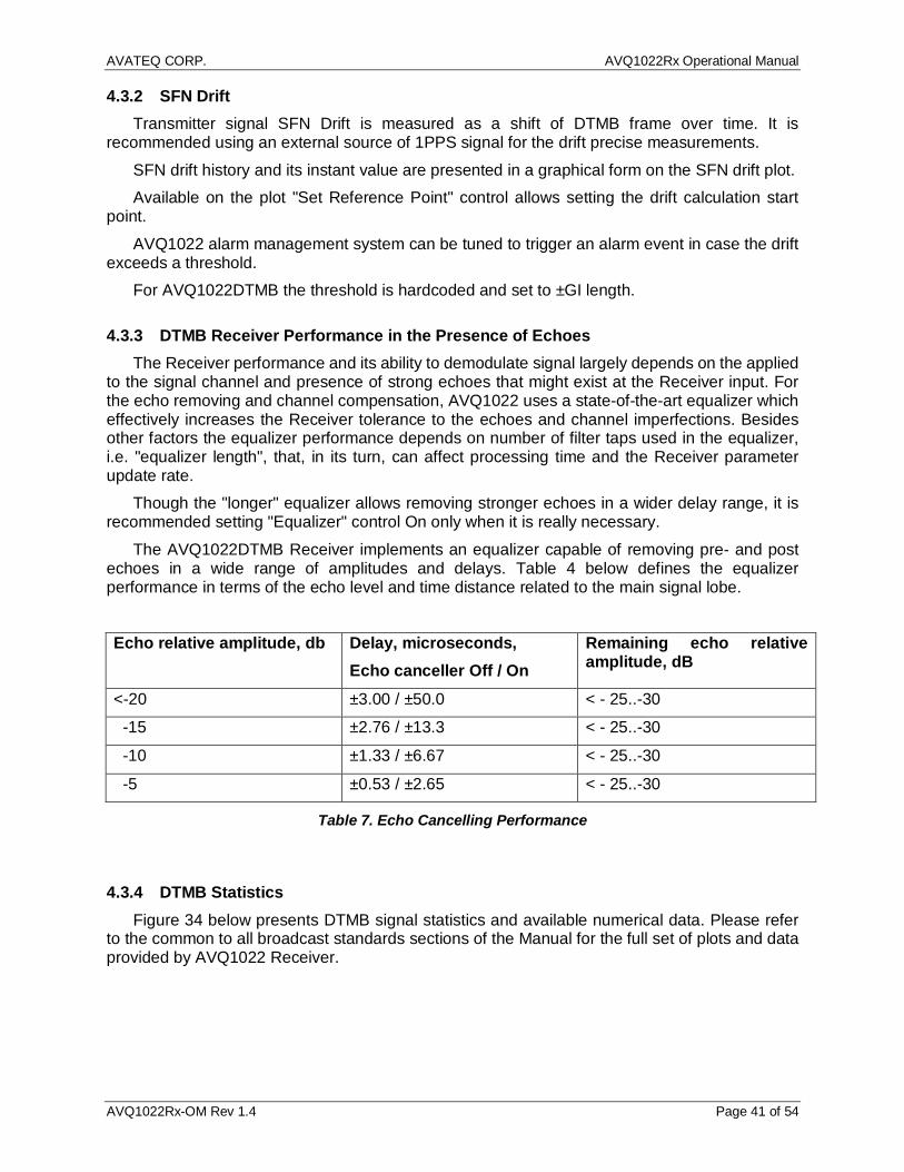
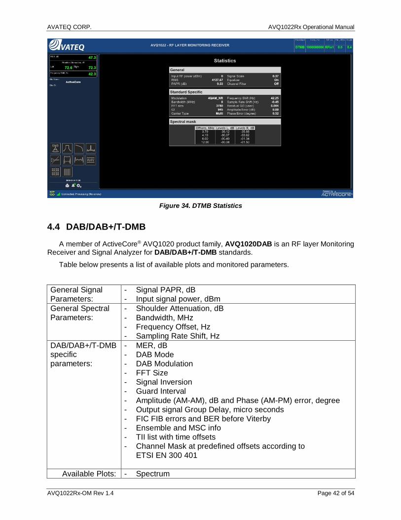
4.3.4 DTMB Statistics Figure 34 below presents DTMB signal statistics and available numerical data. Please refer
to the common to all broadcast standards sections of the Manual for the full set of plots and data provided by AVQ1022 Receiver.
AVATEQ CORP. AVQ1022Rx Operational Manual
AVQ1022Rx-OM Rev 1.4 Page 42 of 54
Figure 34. DTMB Statistics
4.4 DAB/DAB+/T-DMB
A member of ActiveCore® AVQ1020 product family, AVQ1020DAB is an RF layer Monitoring Receiver and Signal Analyzer for DAB/DAB+/T-DMB standards.
Table below presents a list of available plots and monitored parameters.
General Signal Parameters:
- Signal PAPR, dB - Input signal power, dBm
General Spectral Parameters:
- Shoulder Attenuation, dB - Bandwidth, MHz - Frequency Offset, Hz - Sampling Rate Shift, Hz
DAB/DAB+/T-DMB specific parameters:
- MER, dB - DAB Mode - DAB Modulation - FFT Size - Signal Inversion - Guard Interval - Amplitude (AM-AM), dB and Phase (AM-PM) error, degree - Output signal Group Delay, micro seconds - FIC FIB errors and BER before Viterby - Ensemble and MSC info - TII list with time offsets - Channel Mask at predefined offsets according to
ETSI EN 300 401
Available Plots: - Spectrum

AVATEQ CORP. AVQ1022Rx Operational Manual
AVQ1022Rx-OM Rev 1.4 Page 43 of 54
- Constellation Diagram - Symbol MER Diagram - Non-Linear - HPA AM-AM, AM-PM curves - Group Delay, Frequency and Amplitude Response - Echo profile Plot - CCDF Plot - Channel Frequency Response - Event History and Alarm Log - Parameter log - Transmitter SFN Drift
Table 8. Monitored Parameters and Plots – DAB/DAB+/T-DMB
4.4.1 DAB/DAB+/T-DMB Receiver settings Figure 35 below presents settings available when the Receiver is operating in DAB/DAB+/T-
DMB standard.
Figure 35. DAB Receiver Settings
4.4.2 SFN Sync SFN Sync option activates AVQ1022DAB functionality allowing to synchronize (to bind) the
SFN Echo profile pattern with the unit internal clocks. Once synchronized the pattern (Echo) peaks are displayed in the order regardless of the main signal, i.e. the signal from Main

AVATEQ CORP. AVQ1022Rx Operational Manual
AVQ1022Rx-OM Rev 1.4 Page 44 of 54
transmitter, position or amplitude changes. The sync allows to adjust and monitor delays from different transmitters in SFN networks.
Current SFN Sync status is reported on the unit Control->Status page, section “Reference and timing”, see Figure 36 below.
Figure 36. DAB SFN Pattern Sync
4.4.3 SFN Drift Transmitter signal SFN Drift is measured as a variation of NULL symbol appearance at the
transmitter system output of each transmission frame over time. It is recommended using an external source of 1PPS signal for the drift precise measurements.
SFN drift history and its instant value are presented in a graphical form. Available on the plot "Set Reference Point" control allows setting the drift calculation start
point. AVQ1022 alarm management system can be tuned to trigger an alarm event in case the drift
exceeds a threshold. For AVQ1022DAB version of the receiver the threshold is hardcoded and set to +/- GI/2
duration of the correspondent DAB mode.
4.4.4 DAB/DAB+ Streaming Modes AVQ1022DAB supports two streaming modes:
- streaming an audio service to be listened in real-time mode on Host; - streaming a service into a file; the file can be stored on Host and played back later.
The streaming modes can be selected from Mode drop-down menu on AVQ1022 Control Panel->Configuration->Settings page, Figure 37.

AVATEQ CORP. AVQ1022Rx Operational Manual
AVQ1022Rx-OM Rev 1.4 Page 45 of 54
Figure 37. DAB/DAB+ Streaming Options
Below is a step-by-step procedure of setting up AVQ1022 for a streaming mode. The
described steps are common for all supported streaming modes. 1. Tune AVQ1022DAB to a desired frequency (DAB channel) and check that the unit can
demodulate and decode the signal, for example, by checking Ensemble and MSC info section on Statistic page of the unit UI (Figure 38).

AVATEQ CORP. AVQ1022Rx Operational Manual
AVQ1022Rx-OM Rev 1.4 Page 46 of 54
Figure 38. DAB/DAB+ Ensemble and MSC Info
2. Select a desired Streaming option from the drop-down Mode menu on Control
Panel->Configuration->Settings page (Figure 37). 3. Open DAB MUX page (Figure 39) by clicking on “Stream” icon.

AVATEQ CORP. AVQ1022Rx Operational Manual
AVQ1022Rx-OM Rev 1.4 Page 47 of 54
Figure 39. DAB/DAB+ MUX and Service Selection
4. A desired service can be selected/unselected by pressing select/stop button in the correspondent line.
Next steps are different and depend on the Streaming mode option.
4.4.4.1 Streaming an Audio Service Streaming an audio service functionality is switched On by selecting “Stream Audio” option
from the Mode menu. It is assumed that there is VLC Media Player version 2.2.8 installed on Host machine. The
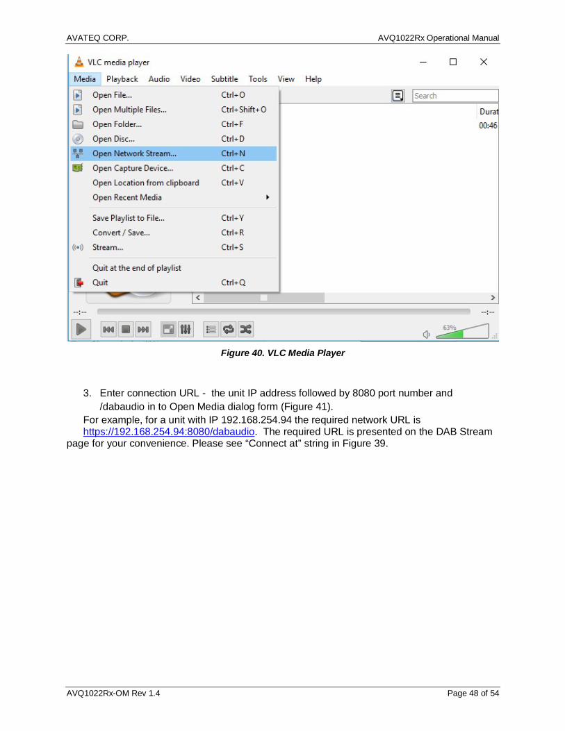
required version can be downloaded from http://download.videolan.org/pub/videolan/vlc/. 1. Run VLC Player 2. Select Media->Open Network Stream to call Open Media dialog (Figure 40) .
AVATEQ CORP. AVQ1022Rx Operational Manual
AVQ1022Rx-OM Rev 1.4 Page 48 of 54
Figure 40. VLC Media Player
3. Enter connection URL - the unit IP address followed by 8080 port number and
/dabaudio in to Open Media dialog form (Figure 41). For example, for a unit with IP 192.168.254.94 the required network URL is https://192.168.254.94:8080/dabaudio. The required URL is presented on the DAB Stream
page for your convenience. Please see “Connect at” string in Figure 39.

AVATEQ CORP. AVQ1022Rx Operational Manual
AVQ1022Rx-OM Rev 1.4 Page 49 of 54
Figure 41. VLC Open Media Dialog
4. Click Play on the VLC Open Media page.
Note: Avateq recommends using VLC Media Player ver. 2.2.8.
4.4.4.2 Streaming a Service into File Streaming a service into file functionality is switched On by selecting “Download audio file ”
option from the Mode menu. 1. Open a new page in your WEB browser; in URL locator of the WEB page enter the same
URL as for VLC Media Player. Please see step 5 description from 4.4.4. 2. Check that a file with selected service will start recording – you should see
dabaudio.mp2(4) (the default file name can not be changed) and number of recorded Mbytes.
3. In order to stop the recording, press “Stop” for the service on DAB Stream page. It is important to Stop the streaming of the service before closing the WEB page.

AVATEQ CORP. AVQ1022Rx Operational Manual
AVQ1022Rx-OM Rev 1.4 Page 50 of 54
Notes: 1. Avateq strongly recommends using Chrome WEB browser for recording a service in to a file.
Possible errors which might occur in Downloading audio file mode are:
- 404 Not Found: the unit is not in Streaming mode, i.e. Stream Off option is selected in the Mode settings.
- HTTP ERROR 503: no service is selected for streaming.
4.5 DVB-S/S2/2x and DVB-CID
A member of ActiveCore® AVQ1022 product family, AVQ1020DVBS is an RF layer Monitoring Receiver and Signal Analyzer for EN 300 421, ETSI EN 302 307, ETSI EN 302 307 – 2 and ETSI TS 103 129 DVB-S/S2/S2x and DVB-CID Standards.
Table below presents a list of available plots and monitored parameters.
General Signal Parameters:
- Signal PAR, dB - Input signal power, dBm
General Spectral Parameters:
- Shoulder Attenuation, dB; - Bandwidth, MHz - Frequency Offset, Hz;
DVB-S/S2 specific parameters:
- MER, dB - EVM, % - SNR, dB - STED, STEM - Eb / No - Signal Inversion - Signal Format DVB-S/S2/S2x - DVB-CID presence and decoding - Constellation and ModCod - FEC frame format, according to ETSI EN 302 307 - DVB-S2/S2x pilots presence - Spectrum mask
Available Plots: - Spectrum - In-band interference spectrum7 - Constellation - Echo Profile Plot - Signal CCDF Plot - Decoded DVB-CID info - MER variation - Event History and Alarm Log - History of Shoulder Attenuation/ MER/PAR variation
7 For DVB-S2 only
AVATEQ CORP. AVQ1022Rx Operational Manual
AVQ1022Rx-OM Rev 1.4 Page 51 of 54
Table 9. Monitored Parameters and Plots – DVB-S/S2/S2X and DVB-CID
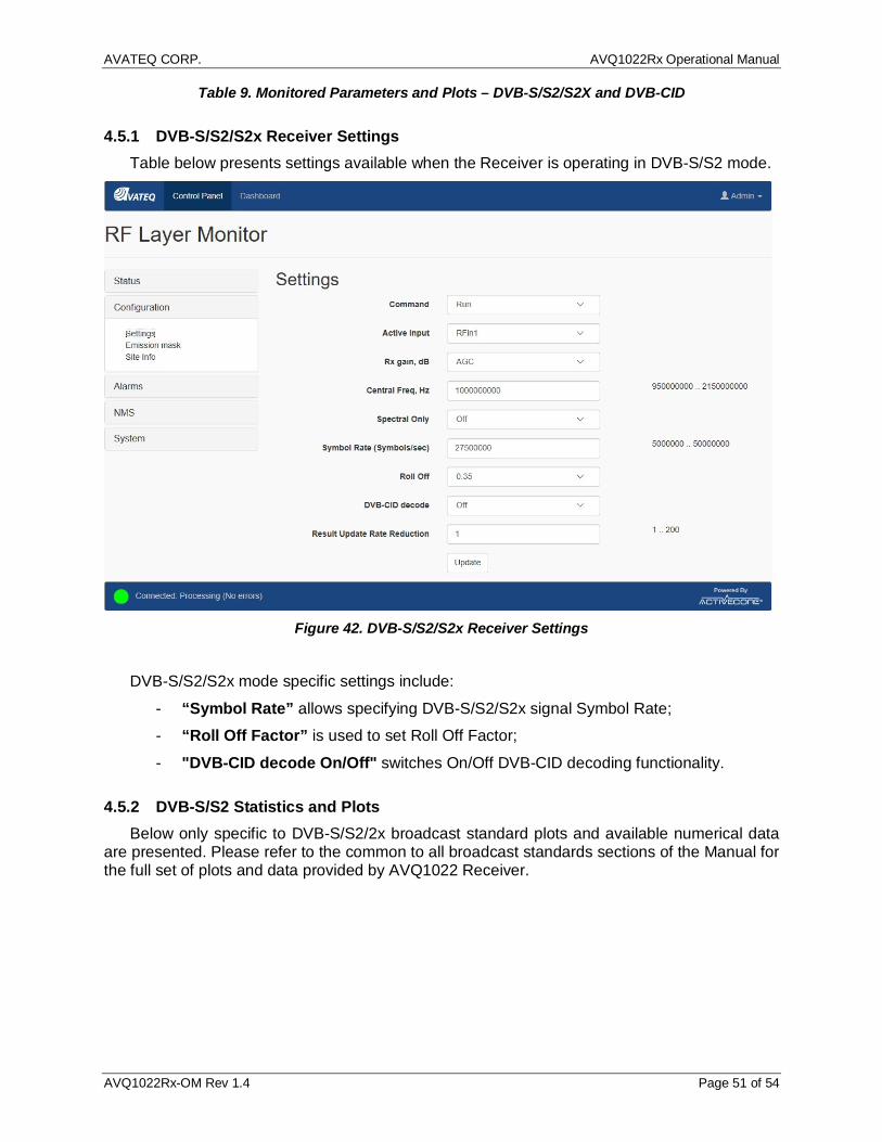
4.5.1 DVB-S/S2/S2x Receiver Settings Table below presents settings available when the Receiver is operating in DVB-S/S2 mode.
Figure 42. DVB-S/S2/S2x Receiver Settings
DVB-S/S2/S2x mode specific settings include:
- “Symbol Rate” allows specifying DVB-S/S2/S2x signal Symbol Rate; - “Roll Off Factor” is used to set Roll Off Factor; - "DVB-CID decode On/Off" switches On/Off DVB-CID decoding functionality.
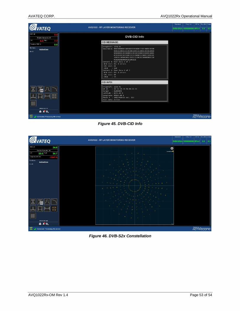
4.5.2 DVB-S/S2 Statistics and Plots Below only specific to DVB-S/S2/2x broadcast standard plots and available numerical data
are presented. Please refer to the common to all broadcast standards sections of the Manual for the full set of plots and data provided by AVQ1022 Receiver.

AVATEQ CORP. AVQ1022Rx Operational Manual
AVQ1022Rx-OM Rev 1.4 Page 52 of 54
Figure 43. DVB-S/S2/S2x Spectrum with In-band DVB-CID Signal
Figure 44. Signal General and DVB-S/S2 Specific Statistics
AVATEQ CORP. AVQ1022Rx Operational Manual
AVQ1022Rx-OM Rev 1.4 Page 53 of 54
Figure 45. DVB-CID Info
Figure 46. DVB-S2x Constellation
AVATEQ CORP. AVQ1022Rx Operational Manual
AVQ1022Rx-OM Rev 1.4 Page 54 of 54
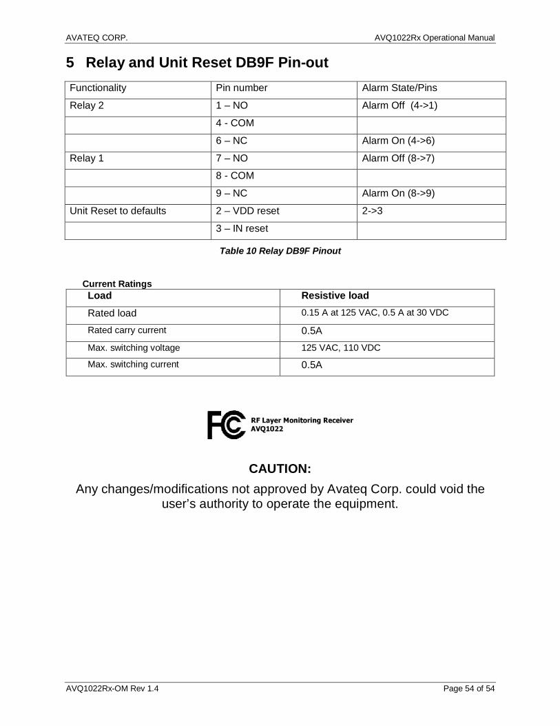
5 Relay and Unit Reset DB9F Pin-out Functionality Pin number Alarm State/Pins
Relay 2 1 – NO Alarm Off (4->1)
4 - COM
6 – NC Alarm On (4->6)
Relay 1 7 – NO Alarm Off (8->7)
8 - COM
9 – NC Alarm On (8->9)
Unit Reset to defaults 2 – VDD reset 2->3
3 – IN reset
Table 10 Relay DB9F Pinout
Current Ratings Load Resistive load Rated load 0.15 A at 125 VAC, 0.5 A at 30 VDC
Rated carry current 0.5A Max. switching voltage 125 VAC, 110 VDC
Max. switching current 0.5A
CAUTION: Any changes/modifications not approved by Avateq Corp. could void the
user’s authority to operate the equipment.