Avoidance of Thermal Damage During Grinding.
66
School of Engineering, Technology and Maritime Operations James Parsons Building, Byrom Street, Liverpool, L3 3AF, UK. 6155ENG Avoidance of Thermal Damage During Grinding. Avoidance of Thermal Damage During Grinding. 6155ENG Engineering Project Final Report Shaun Edwards 623072
-
Upload
shaun-edwards -
Category
Documents
-
view
15 -
download
2
Transcript of Avoidance of Thermal Damage During Grinding.

6155ENGAvoidance of Thermal Damage During Grinding.
Avoidance of Thermal Damage During Grinding.
6155ENG Engineering Project
Final Report
Name: Shaun Michael Edwards
Supervisor: Mr Andy Pettit
Programme: Mechanical Engineering BEng
Date: 02/03/2015
Shaun Edwards623072
School of Engineering, Technology and Maritime Operations James Parsons Building, Byrom Street, Liverpool, L3 3AF, UK.
6155ENGAvoidance of Thermal Damage During Grinding.
Abstract.
“Grinding burn is the most common anomaly in the grinding operation. It is important to detect such anomalies to avoid quality deterioration.” (Chen & Griffin, Grinding Burn and Chatter ClassificationUsing Genetic Prgramming., 2008). It is vital for the advancement of the grinding process that the methods to avoid thermal damage to the workpiece are fully understood and optimised. There are several different thermal models being used to complete this task and in this work, two will be examined and set against experimental data gathered previously. Of the two models examined, the first will be the one initially proposed by Rowe, Pettit, Boyle et al. in their paper (Rowe, Pettit, Boyle,& Moruzzi, 1988) and the second will be the paper proposed 3 years later by Rowe, Morgan and Allanson in (Rowe, Morgan, & Allanson, An Advance in the Modelling of Thermal Effects in theGrinding Process, 1991). The major findings from this paper are the difference in results between the models, as one is a highly conservative model yet one is a much more aggressive and they vary between each other considerably. This means that one of the models could be implemented into industry straight away whereas the other needs refinement and further exploration to be industry ready.
Shaun Edwards623072
2
6155ENGAvoidance of Thermal Damage During Grinding.
Acknowledgements.
I would firstly like to thank my mum, dad, girlfriend and the rest of my family and friends for their
continued support and enthusiasm; they have given me the motivation to complete this project. I
would also like to thank Andy Pettit, Dr David Allanson and Dr Michael Morgan and the rest of the
staff at the School of Engineering, Technology and Maritime Operations at John Moores University as
well as the rest of staff at Liverpool John Moores University. They helped guide me with their
expertise and gave up their time as well as giving me a chance to study at this fantastic university,
without that this project would never have gotten off the ground.
Shaun Edwards623072
3

6155ENGAvoidance of Thermal Damage During Grinding.
Nomenclature.
Symbols. Definition. Units. Equation.
VW Workpiece Velocity. mm * s-1 -
Pn No Load Power. W -
PL Maximum Grinding Power. W -
ds Grind Wheel Diameter. mm -
dW Initial Diameter of the
Workpiece.
mm -
Vf In Feed Rate. mm * s-1 -
Vs Grindwheel velocity. mm * s-1 -
lW Workpiece Length. mm -
Pg Specific Grinding Power. W*mm-1 PL−PnlW
ZW Specific Metal Removal Rate. Mm2*s-1 π2×dw×V f
Us Experimental Critical Specific
Energy.
J * mm3 Pg
ZW
a Depth of Cut. mmπ ×dW×
V f
VW
de Equivalent Diameter. mm dW×dsdW+ds
lg Geometric Contact Length. mm √a×dele Actual Contact Length. mm 3×l g
αW Thermal Diffusivity of the
Workpiece.
m2 * s-1 -
αs Thermal Diffusivity
of the Grind wheel.
m2 * s-1 -
λW Thermal Conductivity of the
Workpiece.
W * m-1 * K-1 -
λs Thermal Conductivity of the
Grind wheel.
W * m-1 * K-1 -
Shaun Edwards623072
4
6155ENGAvoidance of Thermal Damage During Grinding.
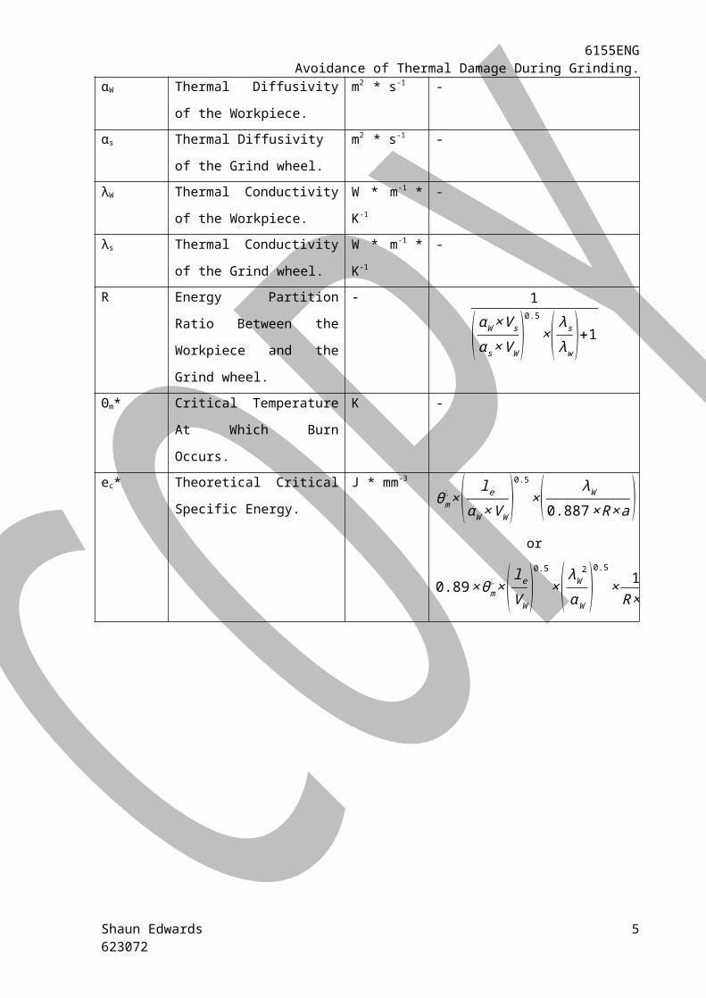
R Energy Partition Ratio
Between the Workpiece and
the Grind wheel.
- 1
(αW×V s
α s×VW)0.5
×( λsλw )+1Θm* Critical Temperature At Which
Burn Occurs.
K -
ec* Theoretical Critical Specific
Energy.
J * mm-3
θm¿ ×( le
αW×VW)0.5
×( λW0.887×R×a )
or
0.89×θm¿ ×( leVW
)0.5
×( λW2
αW )0.5
×1
R×a
Shaun Edwards623072
5
6155ENGAvoidance of Thermal Damage During Grinding.
Table of Contents
Abstract..............................................................................................................................2
Acknowledgements............................................................................................................3
Nomenclature.....................................................................................................................4
1. Introduction....................................................................................................................71.1. The Importance of the Grinding Process.........................................................................................71.2. The Aims and Objectives of the Project...........................................................................................71.3. The Grinding Process.......................................................................................................................81.4 Types of Grinding...........................................................................................................................121.5. Dressing the Grind Wheel..............................................................................................................13
2. Research.......................................................................................................................152.1. What is Thermal Damage?............................................................................................................152.2 The Concept of Thermal Modelling................................................................................................162.3 A Review of Research Concerning the Avoidance of Thermal Damage..........................................17
3. Methodology................................................................................................................21
4. Results..........................................................................................................................22
5. Discussion.....................................................................................................................31
6. Conclusion....................................................................................................................36
Appendix..........................................................................................................................37Appendix I............................................................................................................................................37Appendix II...........................................................................................................................................38Appendix III..........................................................................................................................................42
References........................................................................................................................46
Shaun Edwards623072
6
6155ENGAvoidance of Thermal Damage During Grinding.
1. Introduction.
1.1. The Importance of the Grinding Process.The grinding process is commonly considered to be a finishing process. There are several different
types of grinding processes that are all used for different applications, for example to achieve a good
surface finish or to establish a geometric accuracy etc. Generally grinding is a process in which the
removal rate of the metal, normally hardened steel, is very small when compared to other processes
such as turning or milling. If the removal rate is increased to speed up the process, a problem arises;
this problem is called thermal damage, although in industry it is more commonly known as burn, and
happens to the surface of the workpiece. The problem is to try and speed up the process as much as
possible but without thermal damage being caused to the workpiece.
Grinding is also a process that is hard to automate as opposed to other similar processes; it is
therefore a slow process, and due to the labour intensity, a costly process too. It is therefore
important that the skill level of the grinding operator is very high; which relies heavily on knowledge
of the machine itself and experience from working with the material. It is especially important as by
the time a workpiece reaches the operator many other processes will have been carried out on it.
Each stage of processing adds a value on to the workpiece; therefore by the time it reaches the
grinding stage a significant value will have been added onto it and it will not want to be scrapped at
such a late stage because of a problem, such as thermal damage. It is this problem, the one of
thermal damage, which this research project is looking to overcome.
1.2. The Aims and Objectives of the Project.The aim of this project is to come up with an improved thermal model for the grinding process; one
that can be implemented to as many grinding machines as possible. It will build on pre-existing work
and using previously recorded data and advances in the field, improvements will be suggested other
models too.
There are several different objectives that want to be achieved during the course of this research
project. This entails conducting research into the grinding process, thermal damage and different
thermal models. Once sufficient research has been attained, two thermal models are to be selected
and examined in further detail. Using previously recorded data, calculate the experimental critical
specific energy, then input the data into the thermal models and graph the results of the calculations
to give a visual representation and help portray the findings. The results of the calculations will then
be discussed as to what they illustrate as well as comparing and contrasting the results of each
Shaun Edwards623072
6155ENGAvoidance of Thermal Damage During Grinding.
model. The trueness and precision (British Standards, 1994) etc. of the results will be commented on
as well as the sources of error and any assumptions made. Then using the results, establish which is
most useful and suitable for a process control purpose and to help avoid the workpiece from being
thermally damage. And finally using what has been established through research, propose some
improvements to the thermal models chosen.
1.3. The Grinding Process.
Figure 1.1. A basic example of the grinding zone in a typical surface grinding process. (Marinescu,Rowe, Dimitrov, & Inasaki, 2004)
Figure 1.1. illustrates a typical reciprocating grinding operation taking place, as well as illustrating the
5 key areas in the process: the fluid, the grinding wheel, the atmosphere, the grinding swarf and the
workpiece. The fluid has 3 main jobs, as a: heat sync, lubricating mechanism and transport medium
for swarf. The cooling fluid covers the workpiece and the grinding wheel, and the heat energy that is
in them is then used to evaporate the coolant from the surface. This is similar to how when a person
sweats; the heat energy in them is used to evaporate the sweat that has formed on their skin. This
helps to reduce the temperature in the workpiece from increasing too much and therefore reduces
the risk of thermal damage and other thermal effects from occurring. The fluid also acts as a lubricant
between the abrasive grains in the grinding wheel and the workpiece, thus leading to a reduction in
friction occurring amongst them. This helps keep the abrasive grains relatively sharp, and so reducing
the wear of the grinding wheel as well as making the process a smoother and cleaner one. Due to the
reduction in friction, the lubricating effect also helps to reduce the heat energy being produced and
transferred to the workpiece, so therefore the likelihood of any thermal damage occurring reduces
too. As the liquid is moving through the parts, it helps to rinse the pours of the grinding wheel,
allowing for new swarf to fill those voids. This makes the process more efficient and helps reduce the
need for the wheel to be redressed as often. It also helps to move any swarf away from the
Shaun Edwards623072
8

6155ENGAvoidance of Thermal Damage During Grinding.
workpiece; which helps to keep the machine free from any sizable pieces of sharp metal that could
injure the labourer.
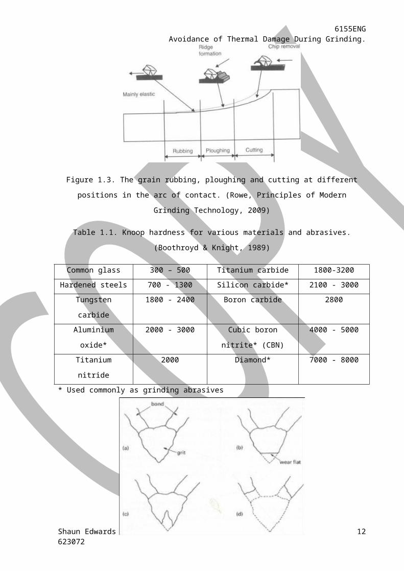
The grinding wheel is the part of the machine that grinds off the metal from the workpiece. It has 3
main constituents, as shown in figure 1.2. They are the grains, the bonds and the pores. The grains
are the part of the wheel that does the work on the product; they carry out three processes on the
metal as shown in figure 1.3. However, rubbing and ploughing aren’t the desired processes; rubbing
occurs when the grit is too blunt and gently rubs along the surface of the workpiece, therefore not
really affecting it much. Ploughing is where the grit penetrates the surface of the workpiece but does
not remove the material it has moved, leaving undesirable ridges along the workpiece. Although
rubbing and ploughing aren’t desirable on their own, it is part of grinding and as long as the cutting
and the chip being removed follow them, it isn’t much to worry about. The grains can be made from
several different materials, summarised in table 1.1. Bonds hold the grains in place; these bonds are
strong enough to withstand the initial forces on the grit, however over a period of time they can fail,
as shown in figure 1.4. The bonds also fail when the grinding wheel is dressed, however this is what
they are designed to do; expose new grains etc. When the chip comes away from the workpiece, if it
is small enough it will potentially occupy the void in the pore of the grinding wheel. This can have
negative effects on the grinding process as it appears to smooth off the grinding wheel. However, it is
making it so there is no difference with the cutting edge of the grain and the chip so nothing can be
ground. Table 1.2. shows the ISO marking system for grinding wheels; this system incorporates 7
categories. The categories are explained below in these helpful guidelines, taken from (Boothroyd &
Knight, 1989), and are to assist with the selection of a grinding wheel:
1. “Choose aluminium oxide for steels, and silicon carbide for carbides and nonferrous metals.
2. Choose a hard-grade wheel for soft materials, and a soft-grade wheel for hard materials.
3. Choose large grit for soft and ductile materials, and small grit for a hard and brittle material.
4. Choose small grit for a good finish, and choose large grit for a maximum metal removal rate.
5. Choose a resinoid, rubber or shellac bond for a good finish, and a vitrified bond for a
maximum metal removal rate.
6. For surface velocity greater than 32 m/s do not choose a vitrified bond.”
(Boothroyd & Knight, 1989)
Shaun Edwards623072
9
6155ENGAvoidance of Thermal Damage During Grinding.
Figure 1.2. Structure of the grinding wheel, made up of grains or grit, the bonds and the pores.
(Marinescu, Rowe, Dimitrov, & Inasaki, 2004).
Figure 1.3. The grain rubbing, ploughing and cutting at different positions in the arc of contact.
(Rowe, Principles of Modern Grinding Technology, 2009)
Table 1.1. Knoop hardness for various materials and abrasives. (Boothroyd & Knight, 1989)
Common glass 300 – 500 Titanium carbide 1800-3200
Hardened steels 700 - 1300 Silicon carbide* 2100 - 3000
Tungsten carbide 1800 - 2400 Boron carbide 2800
Aluminium oxide* 2000 - 3000 Cubic boron nitrite* (CBN) 4000 - 5000
Titanium nitride 2000 Diamond* 7000 - 8000
* Used commonly as grinding abrasives
Shaun Edwards623072
10

6155ENGAvoidance of Thermal Damage During Grinding.
Figure 1.4. Types of wheel wear. (a) freshly dressed grit (b) attritious wear (c) grit fracture (d) bond
fracture. (Andrew, Howes, & Pearce, 1985)
Table 1.2. ISO marking system for grinding wheels. (Boothroyd & Knight, 1989)
The most unobvious element of the grinding process is the atmosphere and the important role it
plays. When a metal is put through a machining process, most of them become slightly chemically
reactive. This is due to two reasons: one, the new layer that has been formed on the surface of the
workpiece is highly reactive, as opposed to the already oxidised surface that has been ground. Two,
the high temperatures involved at the site of contact between the workpiece and the grit speeds up
any slow-moving reactions taking place on the surface. The result of which is that an oxide, or any
other such compounds, is formed rapidly on the newly exposed workpiece surface as well as slightly
on the grit. Oxides can be helpful; they can act as a lubricant if the shear strength of them is low
enough, helping to reduce the frictional force. However as the grind wheel speeds up, the lubrication
effect diminishes.
The grinding swarf is made of several components; these are: the cuts from the workpiece, drops of
the lubricating fluid and any worn grits that have been broken off, or parts of them. Swarf is a useless
product from the grinding process and although it is not value-less, as the metal itself will hold a
value, it is not useful or does it have an impact on the process itself.
In summary, as stated by (Rowe, Principles of Modern Grinding Technology, 2009), grinding relies on
a set of factors and their characteristics. These are:
Shaun Edwards623072
11
6155ENGAvoidance of Thermal Damage During Grinding.
The workpiece material and thus its properties, i.e. its chemical, mechanical, thermal,
physical properties etc. as well as its shape and dimensions.
The type of grinding machine and the accuracy it works to, as well as the control system it is
using, the vibration it is creating and its ability to control the temperature effectively.
The kinematics of both the grind wheel and the workpiece; which include the speeds, the
motion and the in-feed rate.
The grind wheel and its constituent parts, including the grain size, type of bonds and their
make up which influences the abrasiveness of the grind wheel; the hardness, stiffness and its
properties.
The lubricating fluids flow rate, its velocity, pressure and its properties.
(Rowe, Principles of Modern Grinding Technology, 2009)
1.4 Types of Grinding.There are several different types of grinding, which can all be broken down into two main categories:
stock removal grinding (SRO) and form and finishing grinding (FFG). Both of these types of operations
are usually for mainly machining flat or cylindrical surfaces and will vary mostly depending on the
grind wheel, its properties and the kinematic motion of the workpiece. The most common types of
grinding are:
Internal grinding
Cylindrical grinding
Centerless grinding
Creep-feed grinding
Belt grinding
Surface grinding
High energy deep grinding
(Shaw, 1996)
Shaun Edwards623072
12

6155ENGAvoidance of Thermal Damage During Grinding.
Figure 1.5. Diagrams of the operation of grinding machines: (a) cylindrical grinder, (b) internal
grinder, (c) internal grinder with planetary motion, (d) centerless grinder, (e) centerless internal
grinder, (f) surface grinder using the periphery of the wheel, (g) surface grinder using the end of the
wheel; (1) grinding wheel, (2) clamp, (3) workpiece, (4) chuck, (5) regulating wheel, (6) workrest
blade. (Farlex, 2010)
1.5. Dressing the Grind Wheel.As mentioned earlier, a grinding wheel must be dressed. This is a maintenance process that takes
place to ensure efficient, accurate and high quality grinding is consistently produced. It is necessary
that this occurs as after the grind wheel has been in use for a long time, it will not be able to perform
the function to the same level and will lose the accuracy due to a change in their profile. The dressing
process does two jobs: one; it produces the required accuracy of form and profile and true running of
the grinding profile, which is known as ‘truing’. Two; it must generate chip space and sharpness
suitable for the grinding process to take, also known as ‘cleaning up’ (Tawakoli, 1990). In modern day
grinding, the process of truing and cleaning up takes place using one tool at a single time, as opposed
to when separate tools were needed for each job, this singular practice is known as dressing (Slamon,
1992; Chen & Griffin, Grinding burn and chatter classification using genetic programming., 2009). To
dress a grinding wheel by traditional methods requires a specialist-dressing tool. This dressing tool
contains an active cutting surface created by an ultra hard material, which is normally diamonds.
There are several different types of tool, including single and multigrain (Marinescu, Rowe, Dimitrov,
& Inasaki, 2004). It is their job to grind off a fine layer of dull, blunt chips by fracturing the bonds that
hold them together, which unveils new sharper chips along with new empty pores. Whilst doing this,
it helps shape the grinding wheel by levelling off any unevenness in the geometry of the wheel.
Shaun Edwards623072
13
6155ENGAvoidance of Thermal Damage During Grinding.
In relation to thermal damage, when a grind wheel has recently been dressed, it increases the
likelihood of thermal damage occurring. This is due to the fact that if the process has been
automated using a computer numeric control (CNC) system, then the necessary precautions are very
rarely taken to account for the newly dressed grind wheel owing to the considerable time between
dressings. The grit is sharp and the pores are open so it cuts through workpiece easily, this isn’t
accounted for and so the grind wheel is set as if it was blunt and clogged up. This causes as massive
surge in the power consumption by the grind wheel due to the fact it’s easier than it should be to
grind. This energy consumption leads to the workpiece being thermally damaged. However regular
dressing of the grind wheel in time will help the grinding process by optimising the efficiency of the
process and allows for consistent, repeatable results. Over time the wheel wears and the consistency
starts to waver, then the wheel must be dressed again to ensure the efficiency is maximised.
Shaun Edwards623072
14

6155ENGAvoidance of Thermal Damage During Grinding.
2. Research.
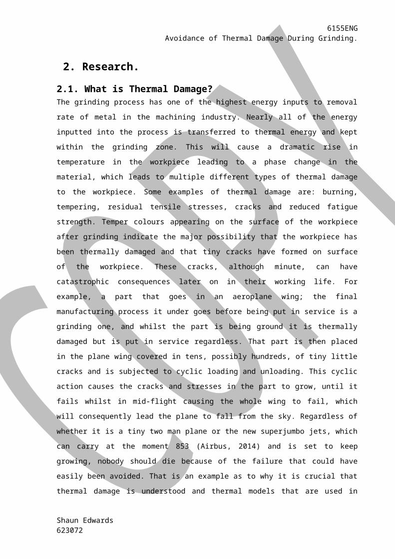
2.1. What is Thermal Damage?The grinding process has one of the highest energy inputs to removal rate of metal in the machining
industry. Nearly all of the energy inputted into the process is transferred to thermal energy and kept
within the grinding zone. This will cause a dramatic rise in temperature in the workpiece leading to a
phase change in the material, which leads to multiple different types of thermal damage to the
workpiece. Some examples of thermal damage are: burning, tempering, residual tensile stresses,
cracks and reduced fatigue strength. Temper colours appearing on the surface of the workpiece after
grinding indicate the major possibility that the workpiece has been thermally damaged and that tiny
cracks have formed on surface of the workpiece. These cracks, although minute, can have
catastrophic consequences later on in their working life. For example, a part that goes in an
aeroplane wing; the final manufacturing process it under goes before being put in service is a
grinding one, and whilst the part is being ground it is thermally damaged but is put in service
regardless. That part is then placed in the plane wing covered in tens, possibly hundreds, of tiny little
cracks and is subjected to cyclic loading and unloading. This cyclic action causes the cracks and
stresses in the part to grow, until it fails whilst in mid-flight causing the whole wing to fail, which will
consequently lead the plane to fall from the sky. Regardless of whether it is a tiny two man plane or
the new superjumbo jets, which can carry at the moment 853 (Airbus, 2014) and is set to keep
growing, nobody should die because of the failure that could have easily been avoided. That is an
example as to why it is crucial that thermal damage is understood and thermal models that are used
in order to avoid this occurring are as accurate as possible to avoid any loss of life.
A visual examination of a workpiece that has been burnt will show the workpiece has adopted a
bluish colour. This is due to the tempering colour change of the workpiece in the order of light brown
to dark brown to violet to blue and how far it goes depends on how badly it has been burnt. The
most accurate way to detect grinding burn is by optical microscope examination of the workpiece
surface once it has been ground, or by having a metallographic etch taken. If an etch is taken, then a
white phase occurrence is shown in patches. However there is a problem with this method of testing
to establish whether the workpiece has been burnt or not; it is a destructive technique. This means
that the workpiece has to be cut down a plane and simply destroyed to establish whether it has been
burnt or not. Therefore, even if the workpiece isn’t burnt, it has been destroyed so badly for the
means of testing that it cannot be used. This means that a passive method of determining whether a
Shaun Edwards623072
6155ENGAvoidance of Thermal Damage During Grinding.
workpiece is damaged or not during the process is needed (Nathan, Vijayaraghavan, &
Krishnamurthy , 1999).
When predicting the burn threshold, the most important aspect to consider is the temperature that
onset of burn occurs for that particular material. When grinding, with steels especially, it is important
to look at the thermal properties of that individual compound as they can vary quite considerably
depending on the percentage alloy content. In ferrous metals, temper colours will appear at
temperature values as low as 220°C in dry grinding, so thermal damage could have occurred slightly
lower than that (Rowe, Pettit, Boyle, & Moruzzi, 1988). However if a cooling fluid is used in the
process the workpiece can be ground above the critical energy that corresponded to 220°C; this is
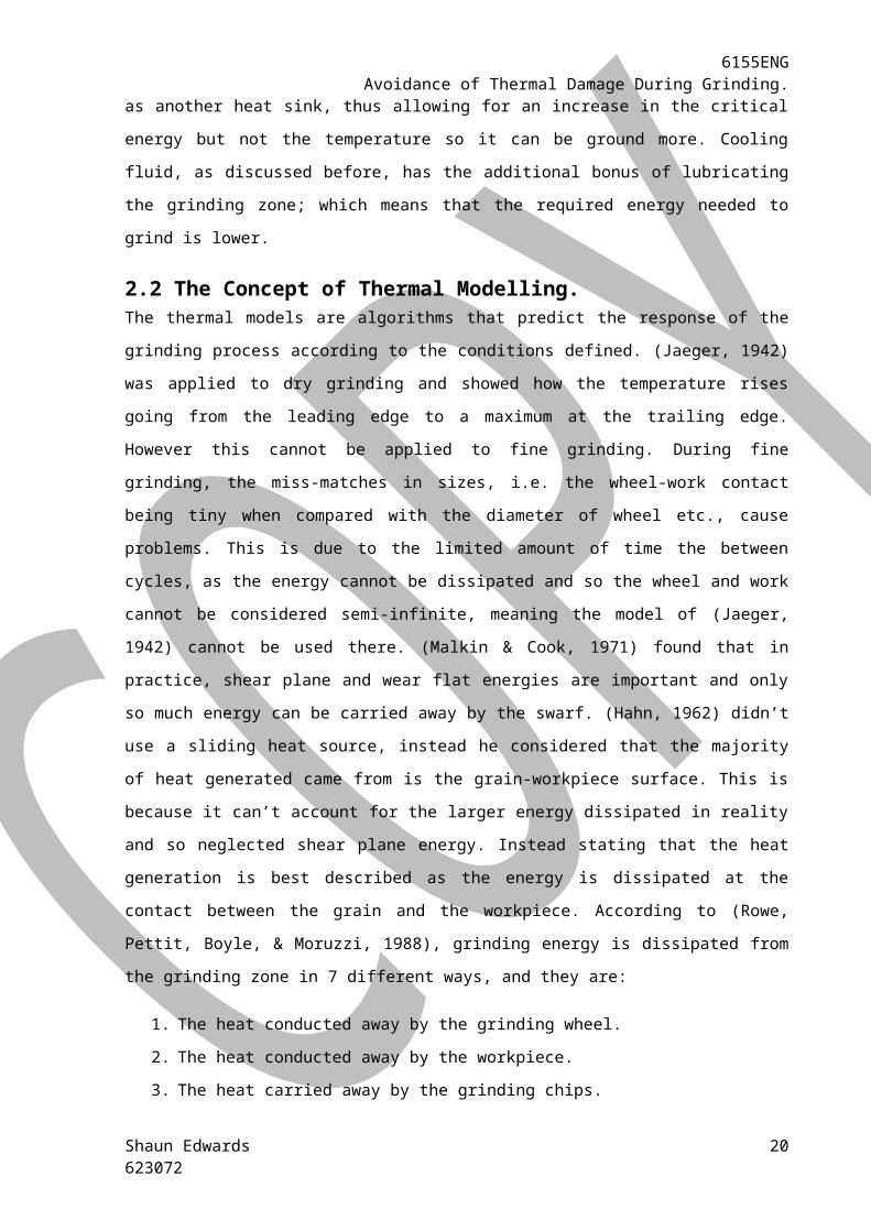
because the cooling fluid acts as another heat sink, thus allowing for an increase in the critical energy
but not the temperature so it can be ground more. Cooling fluid, as discussed before, has the
additional bonus of lubricating the grinding zone; which means that the required energy needed to
grind is lower.
2.2 The Concept of Thermal Modelling.The thermal models are algorithms that predict the response of the grinding process according to the
conditions defined. (Jaeger, 1942) was applied to dry grinding and showed how the temperature
rises going from the leading edge to a maximum at the trailing edge. However this cannot be applied
to fine grinding. During fine grinding, the miss-matches in sizes, i.e. the wheel-work contact being
tiny when compared with the diameter of wheel etc., cause problems. This is due to the limited
amount of time the between cycles, as the energy cannot be dissipated and so the wheel and work
cannot be considered semi-infinite, meaning the model of (Jaeger, 1942) cannot be used there.
(Malkin & Cook, 1971) found that in practice, shear plane and wear flat energies are important and
only so much energy can be carried away by the swarf. (Hahn, 1962) didn’t use a sliding heat source,
instead he considered that the majority of heat generated came from is the grain-workpiece surface.
This is because it can’t account for the larger energy dissipated in reality and so neglected shear
plane energy. Instead stating that the heat generation is best described as the energy is dissipated at
the contact between the grain and the workpiece. According to (Rowe, Pettit, Boyle, & Moruzzi,
1988), grinding energy is dissipated from the grinding zone in 7 different ways, and they are:
1. The heat conducted away by the grinding wheel.
2. The heat conducted away by the workpiece.
3. The heat carried away by the grinding chips.
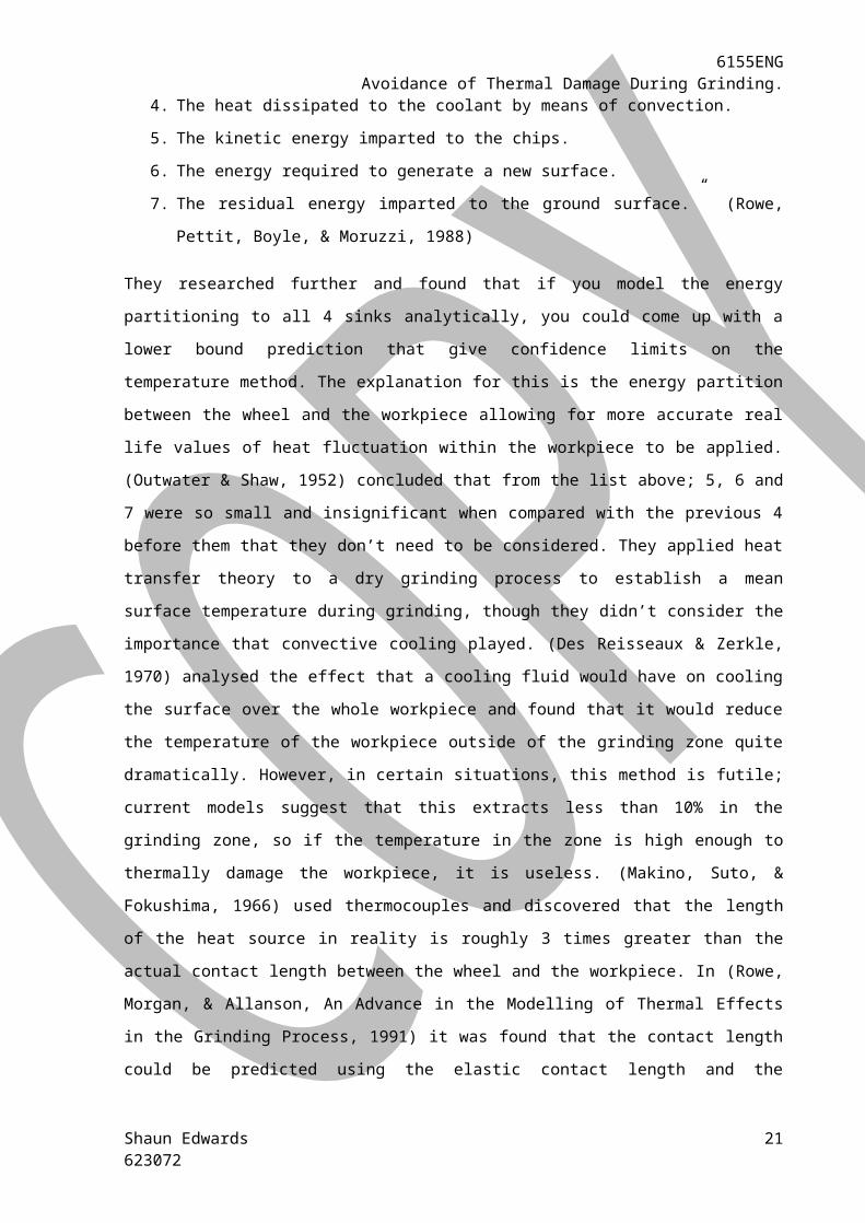
4. The heat dissipated to the coolant by means of convection.
5. The kinetic energy imparted to the chips.
Shaun Edwards623072
16
6155ENGAvoidance of Thermal Damage During Grinding.
6. The energy required to generate a new surface.
7. The residual energy imparted to the ground surface.” (Rowe, Pettit, Boyle, & Moruzzi, 1988)
They researched further and found that if you model the energy partitioning to all 4 sinks analytically,
you could come up with a lower bound prediction that give confidence limits on the temperature
method. The explanation for this is the energy partition between the wheel and the workpiece
allowing for more accurate real life values of heat fluctuation within the workpiece to be applied.
(Outwater & Shaw, 1952) concluded that from the list above; 5, 6 and 7 were so small and
insignificant when compared with the previous 4 before them that they don’t need to be considered.
They applied heat transfer theory to a dry grinding process to establish a mean surface temperature
during grinding, though they didn’t consider the importance that convective cooling played. (Des
Reisseaux & Zerkle, 1970) analysed the effect that a cooling fluid would have on cooling the surface
over the whole workpiece and found that it would reduce the temperature of the workpiece outside
of the grinding zone quite dramatically. However, in certain situations, this method is futile; current
models suggest that this extracts less than 10% in the grinding zone, so if the temperature in the
zone is high enough to thermally damage the workpiece, it is useless. (Makino, Suto, & Fokushima,
1966) used thermocouples and discovered that the length of the heat source in reality is roughly 3
times greater than the actual contact length between the wheel and the workpiece. In (Rowe,
Morgan, & Allanson, An Advance in the Modelling of Thermal Effects in the Grinding Process, 1991) it
was found that the contact length could be predicted using the elastic contact length and the
geometric one. (Howes, Neaily, & Harrison, 1987) found that if the temperature in the grinding zone
goes above the temperature at which the cooling fluid boils, it will lead to a drastic reduction in the
heat transferred to the coolant and the lubrication effect of the liquid. This is known as the fluid film
boiling effect and due to the coolant not being an effective heat sink; it causes the temperature in
zone to rise even more, usually resulting in the workpiece being burnt. Consequently, it can be
concluded that the maximum energy that can be imparted into the coolant is limited by the
minimum amount energy required to boil the coolant. (Rowe, Black, Mills, Morgan, & Qi, 1997)
explored the critical temperatures at which the onset of burn occurs and found that generally it falls
between 450 and 500°C for ferrous metals.
2.3 A Review of Research Concerning the Avoidance of Thermal Damage.It is important to define what the ‘grinding zone temperature’ and the ‘local grinding temperature’
actually are so there is no confusion. The localised grinding temperature is the temperature
generated by the energy of the grinding actions of a single grain in isolation from the rest of the
grinding wheel. The grinding zone temperature is the rise in the temperature due to the energy of
Shaun Edwards623072
17
6155ENGAvoidance of Thermal Damage During Grinding.
the collective grinding action of all of the grains. (Jaeger, 1942) developed this by considering the
grinding zone as a two-dimensional perfect insulator of length, l, moving along a semi infinite body
with a velocity, v. This is displayed in figure 2.1.
Figure 2.1. A two dimensional perfect insulator with length, l, moving over a semi-infinite body with a
velocity, v. (Shaw, 1996)
Most of the recent work in this field is based on the work of (Jaeger, 1942) and the perfect insulator
moving across a semi-infinite body idea he used, shown in figure 2.1. This theory predicts the
temperature at the contact of the workpiece during grinding and so has been used and expanded on
in great detail. It is the basis of nearly all of the modern day models.
As discussed earlier, (Des Reisseaux & Zerkle, 1970) looked into the where the heat energy is
dissipated to. They built on the work of (Jaeger, 1942) and found that if the coolant could get into,
and affect, the localised grinding area it would work quite effectively.
Thermal modelling relies on the partitioning of the heat generated through grinding. This is because
not all of the heat generate through grinding goes into the workpiece. Knowing how much of the
total heat energy generated flows into the workpiece enables the critical temperature at which the
onset thermal damage occurs to be calculated. Many researchers have looked at the values of how
much energy goes into the workpiece and their approximations are shown in the table below as a
percentage:
Table 2.1 showing the percentage of heat energy flowing into the workpiece and the swarf and wheel
that different researchers found and how they established the percentage.
Shaun Edwards623072
18

6155ENGAvoidance of Thermal Damage During Grinding.
Author Percentage entering
the workpiece
Percentage entering
the swarf & wheel
Comment
Saucer 30-70 70-30 Experimental
Lee 80 20 Experimental
Malkin 60-80 40-20 Experimental
Sato 84 16 Experimental
Outwater & Shaw 35 65 Theoretical
Eshghy 10 90 Theoretical
The reason for Sauer’s results varying so much is that he found that increasing the removal rate lead
to a decrease in the energy entering the workpiece. (Malkin & Cook, 1971) research found how the
sharpness of the grind wheel affects the total energy entering the workpiece, so the blunter the grind
wheel gets, the more energy enters the workpiece.
As discussed earlier, the length of contact between the workpiece and the grind wheel is not always
as it seems. (Makino, Suto, & Fokushima, 1966) discovered, through their work with applying
thermocouples to the process, that the real contact length could be as much as 3 times greater than
the geometric contact length. (Rowe, Morgan, & Allanson, An Advance in the Modelling of Thermal
Effects in the Grinding Process, 1991) found that the actual contact length depends on the elasticity
of the grind wheel and the workpiece. They did this using computer modelling and testing on
different grinding machines.
(Outwater & Shaw, 1952) looked at what the grinding temperature would be if all of the energy
generated went into the chips and from that determined that 35% of the shear energy generated
went into the workpiece. (Malkin & Cook, 1971) found that the energy generated is the sum of the
energy generated through the three stages of the chip grinding; cutting, ploughing and rubbing.
Using the idea that (Jaeger, 1942) came up with about sliding energy, (Malkin & Cook, 1971) showed
how nearly all sliding energy is conducted to the workpiece and how as the wheel becomes blunt the
energy being imparted increases. However very little energy is transferred due to chips cutting and
using a sharp grind-wheel, showing the importance of dressing the workpiece regularly.
The work conducted by Rowe, Pettit, Boyle et al. in their paper (Rowe, Pettit, Boyle, & Moruzzi, 1988)
came up with a method of predicting the burn threshold limit by using some of the parameters and
characteristics involved in the grinding process. This work was a break through as it used a new
concept of energy partitioning that allowed the percentage entering the workpiece to change
Shaun Edwards623072
19
6155ENGAvoidance of Thermal Damage During Grinding.
depending on the workpiece velocity. This allows for a more realistic value of heat flux to be applied
to the critical specific energy equation. This, along with the improvements to the critical specific
energy calculation, allowed a more accurate model to be developed. This model was the most
accurate to date when published.
Building on the work of Rowe, Pettit, Boyle et al; Rowe, Morgan and Allanson wrote a paper (Rowe,
Morgan, & Allanson, An Advance in the Modelling of Thermal Effects in the Grinding Process, 1991) .
This paper looked at the difference between the wheel-workpiece contact zone and the average
grain contact zone; if a distinction is not made between the two then conceptual difficulties may
arise due to the difference in the relative speeds. They then used this to come up with a more
conservative method of burn prediction, which could be used in industry straight away.
Shaun Edwards623072
20
6155ENGAvoidance of Thermal Damage During Grinding.
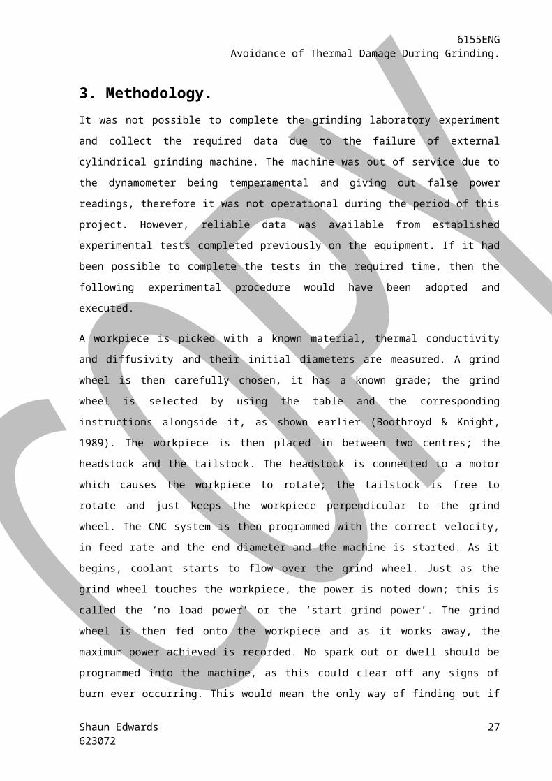
3. Methodology.
It was not possible to complete the grinding laboratory experiment and collect the required data due
to the failure of external cylindrical grinding machine. The machine was out of service due to the
dynamometer being temperamental and giving out false power readings, therefore it was not
operational during the period of this project. However, reliable data was available from established
experimental tests completed previously on the equipment. If it had been possible to complete the
tests in the required time, then the following experimental procedure would have been adopted and
executed.
A workpiece is picked with a known material, thermal conductivity and diffusivity and their initial
diameters are measured. A grind wheel is then carefully chosen, it has a known grade; the grind
wheel is selected by using the table and the corresponding instructions alongside it, as shown earlier
(Boothroyd & Knight, 1989). The workpiece is then placed in between two centres; the headstock
and the tailstock. The headstock is connected to a motor which causes the workpiece to rotate; the
tailstock is free to rotate and just keeps the workpiece perpendicular to the grind wheel. The CNC
system is then programmed with the correct velocity, in feed rate and the end diameter and the
machine is started. As it begins, coolant starts to flow over the grind wheel. Just as the grind wheel
touches the workpiece, the power is noted down; this is called the ‘no load power’ or the ‘start grind
power’. The grind wheel is then fed onto the workpiece and as it works away, the maximum power
achieved is recorded. No spark out or dwell should be programmed into the machine, as this could
clear off any signs of burn ever occurring. This would mean the only way of finding out if burn has
occurred would be to destroy the sample and take a metallographic etch of the sample. The grind
wheel then retracts quickly back to its starting position and the power is stopped being supplied to
the motors so they come to rest. There is little backlash involved in a CNC programmed machine due
to the type of lead screw used in the machine so this should not be a problem during the testing.
In industry, a spark out would be programmed into the machine; this is done to allow the machine to
relax and therefore can guarantee the dimensional accuracy of the workpiece.
Shaun Edwards623072
21

6155ENGAvoidance of Thermal Damage During Grinding.
4. Results.
Table 4.1 The results table for the original test.
Shaun Edwards623072
Workpiece
no. Vw
Dressed
? Pn PL
Burnt
? ds dW lW Vf Vs
1 5 Yes
81
6
734
4 Yes
44
1
43.34
7
4
7
0.012
0
3300
0
2 5 No
81
9
610
8 Yes
44
1
43.34
7
4
7
0.012
0
3300
0
3 6 No
81
6
548
4 Yes
44
1
43.34
8
4
7
0.012
0
3300
0
4 7 No
81
6
496
8 No
44
1
43.35
1
4
7
0.012
0
3300
0
5 8 No
81
3
478
5 No
44
1 43.35
4
7
0.012
0
3300
0
6 9 No
81
9
459
0 No
44
1 43.35
4
7
0.012
0
3300
0
7 10 No
81
3
452
1 No
44
1
43.45
1
4
7
0.012
0
3300
0
8 11 No
81
6
442
2 No
44
1
43.35
1
4
7
0.012
0
3300
0
9 12 No
81
9
440
7 No
44
1
43.35
2
4
7
0.012
0
3300
0
10 13 No
81
3
434
4 No
44
1
43.35
2
4
7
0.012
0
3300
0
11 14 No
81
3
458
7 No
44
1
43.35
4
4
7
0.012
0
3300
0
12 15 No
81
0
416
7 No
44
1
43.35
5
4
7
0.012
0
3300
0
13 17 No
81
0
462
3 No
44
1
43.35
5
4
7
0.012
0
3300
0
14 19 No
81
6
393
6 No
44
1
43.35
6
4
7
0.012
0
3300
0
15 19 Yes
81
0
693
0 Yes
44
1
43.35
6
4
7
0.012
0
3300
0 22

6155ENGAvoidance of Thermal Damage During Grinding.
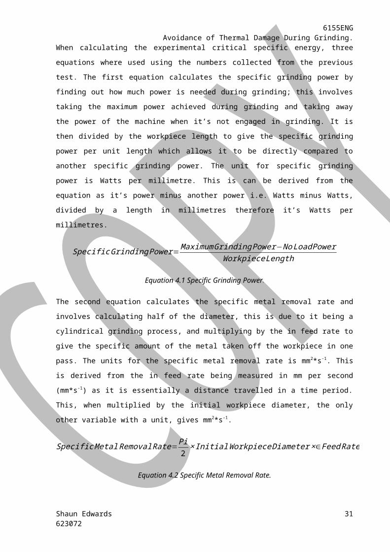
When calculating the experimental critical specific energy, three equations where used using the
numbers collected from the previous test. The first equation calculates the specific grinding power by
finding out how much power is needed during grinding; this involves taking the maximum power
achieved during grinding and taking away the power of the machine when it’s not engaged in
grinding. It is then divided by the workpiece length to give the specific grinding power per unit length
which allows it to be directly compared to another specific grinding power. The unit for specific
grinding power is Watts per millimetre. This is can be derived from the equation as it’s power minus
another power i.e. Watts minus Watts, divided by a length in millimetres therefore it’s Watts per
millimetres.
SpecificGrinding Power=MaximumGrinding Power−NoLoad PowerWorkpiece Length
Equation 4.1 Specific Grinding Power.
The second equation calculates the specific metal removal rate and involves calculating half of the
diameter, this is due to it being a cylindrical grinding process, and multiplying by the in feed rate to
give the specific amount of the metal taken off the workpiece in one pass. The units for the specific
metal removal rate is mm2*s-1. This is derived from the in feed rate being measured in mm per
second (mm*s-1) as it is essentially a distance travelled in a time period. This, when multiplied by the
initial workpiece diameter, the only other variable with a unit, gives mm2*s-1.
SpecificMetal Removal Rate=Pi2×InitialWorkpiece Diameter ×∈Feed Rate
Equation 4.2 Specific Metal Removal Rate.
The final equation uses the two previous equations and divides the first by the second to give the
critical specific energy. Essentially it is the power used to remove a specific amount of the workpiece.
Taking the units derived for the first equation and putting Watts into its derivative of J*s -1 gives the
units of specific grinding power as J*mm-1*s-1.Using the improved units for specific grinding power
and mm2*s-1 for the specific metal removal rate, the units for the critical specific energy can be
derived. This is shown in detail in equation 4.4.
ExperimentalCritical Specific Energy= SpecificGrinding PowerSpecificMetal Removal Rate
Equation 4.3 Experimental Critical Specific Energy.
Shaun Edwards623072
23

6155ENGAvoidance of Thermal Damage During Grinding.
Jmm×s
÷mm2
s≡
Jmm×s
×s
mm2≡
J×smm×s×mm2
≡Jmm3
Equation 4.4 derivation of critical specific energy units.
Shaun Edwards623072
24

6155ENGAvoidance of Thermal Damage During Grinding.
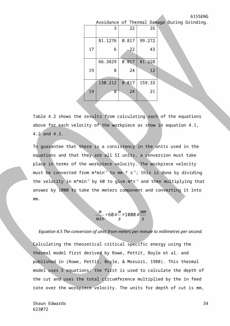
Table 4.2 The results table for calculating the experimental critical specific energy.
Vw Pg Zw Us
5 138.8936 0.81707 169.9895
5 112.5319 0.81707 137.7259
6 99.31915 0.81709 121.5522
7 88.34043 0.81715 108.1084
8 84.51064 0.81713 103.424
9 80.23404 0.81713 98.19027
10 78.89362 0.81903 96.32543
11 76.7234 0.81715 93.89179
12 76.34043 0.81717 93.42096
13 75.12766 0.81717 91.93685
14 80.29787 0.8172 98.25932
15 71.42553 0.81722 87.40035
17 81.12766 0.81722 99.27243
19 66.38298 0.81724 81.22812
19 130.2128 0.81724 159.3321
Table 4.2 shows the results from calculating each of the equations above for each velocity of the
workpiece as show in equation 4.1, 4.2 and 4.3.
To guarantee that there is a consistency in the units used in the equations and that they are all SI
units, a conversion must take place in terms of the workpiece velocity. The workpiece velocity must
be converted from m*min-1 to mm * s-1; this is done by dividing the velocity in m*min-1 by 60 to give
m*s-1 and then multiplying that answer by 1000 to take the meters component and converting it into
mm.
Shaun Edwards623072
25

6155ENGAvoidance of Thermal Damage During Grinding.
mmin
÷60≡ms×1000≡
mms
Equation 4.5 The conversion of units from meters per minute to millimetres per second.
Calculating the theoretical critical specific energy using the thermal model first derived by Rowe,
Pettit, Boyle et al. and published in (Rowe, Pettit, Boyle, & Moruzzi, 1988). This thermal model uses 5
equations; the first is used to calculate the depth of the cut and uses the total circumference
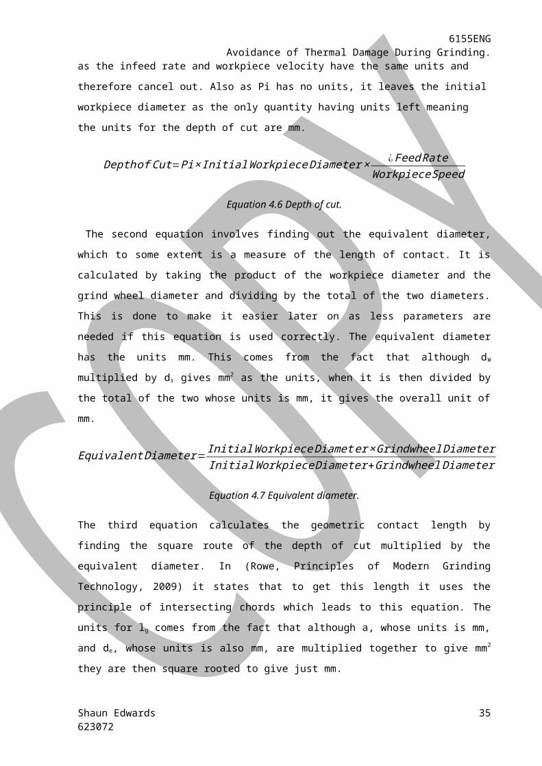
multiplied by the in feed rate over the workpiece velocity. The units for depth of cut is mm, as the
infeed rate and workpiece velocity have the same units and therefore cancel out. Also as Pi has no
units, it leaves the initial workpiece diameter as the only quantity having units left meaning the units
for the depth of cut are mm.
Depthof Cut=Pi× InitialWorkpiece Diameter × ¿Feed RateWorkpieceSpeed
Equation 4.6 Depth of cut.
The second equation involves finding out the equivalent diameter, which to some extent is a
measure of the length of contact. It is calculated by taking the product of the workpiece diameter
and the grind wheel diameter and dividing by the total of the two diameters. This is done to make it
easier later on as less parameters are needed if this equation is used correctly. The equivalent
diameter has the units mm. This comes from the fact that although dW multiplied by ds gives mm2 as
the units, when it is then divided by the total of the two whose units is mm, it gives the overall unit of
mm.
Equivalent Diameter= InitialWorkpiece Diamet er ×Grindwheel DiameterInitialWorkpiece Diameter+GrindwheelDiameter
Equation 4.7 Equivalent diameter.
The third equation calculates the geometric contact length by finding the square route of the depth
of cut multiplied by the equivalent diameter. In (Rowe, Principles of Modern Grinding Technology,
2009) it states that to get this length it uses the principle of intersecting chords which leads to this
equation. The units for lg comes from the fact that although a, whose units is mm, and de, whose
units is also mm, are multiplied together to give mm2 they are then square rooted to give just mm.
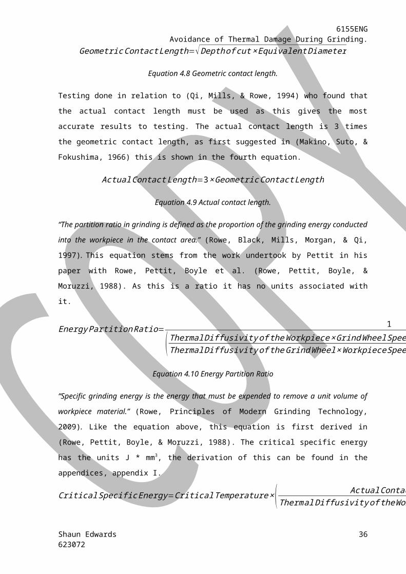
Geometric Contact Length=√Depthof cut× Equivalent Diameter
Equation 4.8 Geometric contact length.
Shaun Edwards623072
26
6155ENGAvoidance of Thermal Damage During Grinding.
Testing done in relation to (Qi, Mills, & Rowe, 1994) who found that the actual contact length must
be used as this gives the most accurate results to testing. The actual contact length is 3 times the
geometric contact length, as first suggested in (Makino, Suto, & Fokushima, 1966) this is shown in the
fourth equation.
ActualContact Length=3×Geometric Contact Length
Equation 4.9 Actual contact length.
“The partition ratio in grinding is defined as the proportion of the grinding energy conducted into the
workpiece in the contact area.” (Rowe, Black, Mills, Morgan, & Qi, 1997). This equation stems from
the work undertook by Pettit in his paper with Rowe, Pettit, Boyle et al. (Rowe, Pettit, Boyle, &
Moruzzi, 1988). As this is a ratio it has no units associated with it.
Energy PartitionRatio= 1
(Thermal Diffusivity of theWorkpiece×GrindWheel SpeedThermal Diffusivity of theGrindWheel×WorkpieceSpeed )0.5
×ThermalConductivity of theGrindwheelThermal Conductivity of theWorkpiece
+1
Equation 4.10 Energy Partition Ratio
“Specific grinding energy is the energy that must be expended to remove a unit volume of workpiece
material.” (Rowe, Principles of Modern Grinding Technology, 2009). Like the equation above, this
equation is first derived in (Rowe, Pettit, Boyle, & Moruzzi, 1988). The critical specific energy has the
units J * mm3, the derivation of this can be found in the appendices, appendix I.
Critical Specific Energy=Critical Temperature×( ActualContact LengthThermal Diffusivity of theWorkpiece×WorkpieceSpeed )
0.5
×Thermal Conductivity of theWorkpiece
0.887× Energy PartitionRatio×Depthof Cut
Equation 4.11 Theoretical critical specific energy according to Rowe, Pettit, Boyle et al.
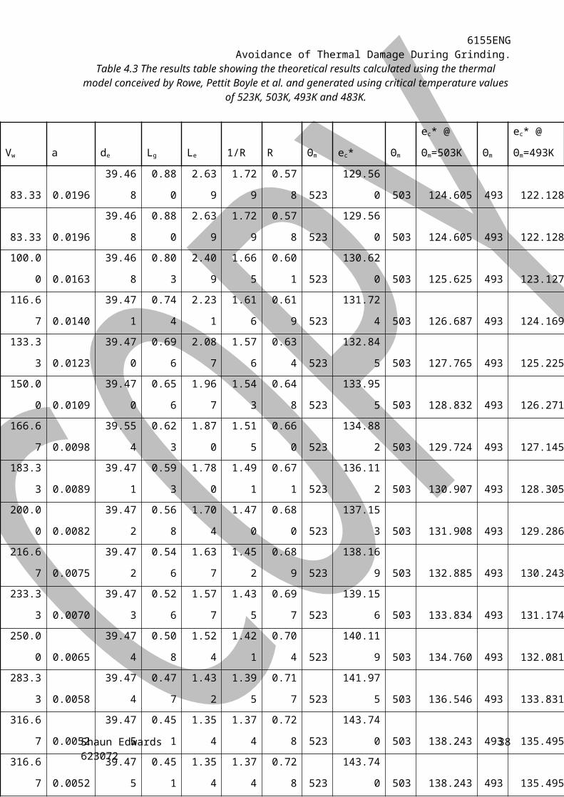
The results table is presented below (Table 4.3) and the full results table is disclosed in the
appendices as well as the table in it is equation form, appendix II. These results have then been
plotted on a graph (Figure 4.1) of critical specific energy against workpiece velocity, the red points on
the experimental critical specific energy line are the experiments at which burn occurs and the
hollow blue markers are the experiments where burn didn’t occur.
Shaun Edwards623072
27

6155ENGAvoidance of Thermal Damage During Grinding.
Table 4.3 The results table showing the theoretical results calculated using the thermal model conceived by Rowe, Pettit Boyle et al. and generated using critical temperature values of 523K, 503K,
493K and 483K.
Figure 4.1 A graph showing the theoretical & experimental critical specific energy against the workpiece velocity using the Rowe, Pettit, Boyle et al. model.
Shaun Edwards623072
70.00 120.00 170.00 220.00 270.00 320.000.00
20.00
40.00
60.00
80.00
100.00
120.00
140.00
160.00
180.00
A graph to show the theoretical and experimental critical specific energy generated during the grinding process against the workpiece velocity using the Rowe, Pettit Boyle et al.
thermal model.
Experimental Critical Specific Energy Theoretical Critical Specific Energy @ 523K Theoretical Critical Specific Energy @ 503K Theoretical Critical Specific Energy @ 493K Theoretical Critical Specific Energy @ 483K
Workpiece Velocity (mm/s)
Criti
cal S
pecifi
c Ene
rgy
(J/m
m3)
28
Vw a de Lg Le 1/R R ϴm ec* ϴm
ec* @
ϴm=503K ϴm
ec* @
ϴm=493K
83.33 0.0196 39.468 0.880 2.639 1.729 0.578 523 129.560 503 124.605 493 122.128
83.33 0.0196 39.468 0.880 2.639 1.729 0.578 523 129.560 503 124.605 493 122.128
100.00 0.0163 39.468 0.803 2.409 1.665 0.601 523 130.620 503 125.625 493 123.127
116.67 0.0140 39.471 0.744 2.231 1.616 0.619 523 131.724 503 126.687 493 124.169
133.33 0.0123 39.470 0.696 2.087 1.576 0.634 523 132.845 503 127.765 493 125.225
150.00 0.0109 39.470 0.656 1.967 1.543 0.648 523 133.955 503 128.832 493 126.271
166.67 0.0098 39.554 0.623 1.870 1.515 0.660 523 134.882 503 129.724 493 127.145
183.33 0.0089 39.471 0.593 1.780 1.491 0.671 523 136.112 503 130.907 493 128.305
200.00 0.0082 39.472 0.568 1.704 1.470 0.680 523 137.153 503 131.908 493 129.286
216.67 0.0075 39.472 0.546 1.637 1.452 0.689 523 138.169 503 132.885 493 130.243
233.33 0.0070 39.473 0.526 1.577 1.435 0.697 523 139.156 503 133.834 493 131.174
250.00 0.0065 39.474 0.508 1.524 1.421 0.704 523 140.119 503 134.760 493 132.081
283.33 0.0058 39.474 0.477 1.432 1.395 0.717 523 141.975 503 136.546 493 133.831
316.67 0.0052 39.475 0.451 1.354 1.374 0.728 523 143.740 503 138.243 493 135.495
316.67 0.0052 39.475 0.451 1.354 1.374 0.728 523 143.740 503 138.243 493 135.495
6155ENGAvoidance of Thermal Damage During Grinding.
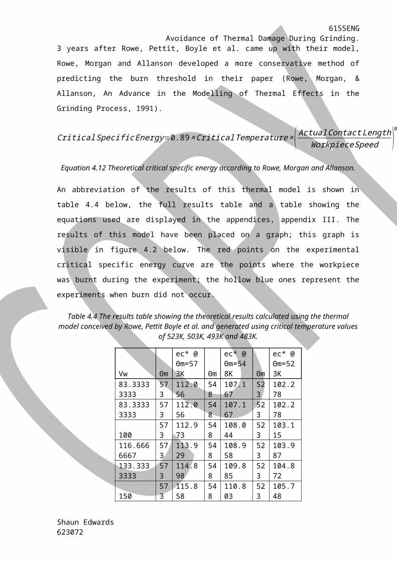
3 years after Rowe, Pettit, Boyle et al. came up with their model, Rowe, Morgan and Allanson
developed a more conservative method of predicting the burn threshold in their paper (Rowe,
Morgan, & Allanson, An Advance in the Modelling of Thermal Effects in the Grinding Process, 1991).
Critical Specific Energy=0.89×Critical Temperature×( ActualContact LengthWorkpiece Speed )0.5
×(ThermalConductivity of theWorkpiece2Thermal Diffusivity of theWorkpiece )0.5
×1
Energy PartitionRatio×Depthof Cut
Equation 4.12 Theoretical critical specific energy according to Rowe, Morgan and Allanson.
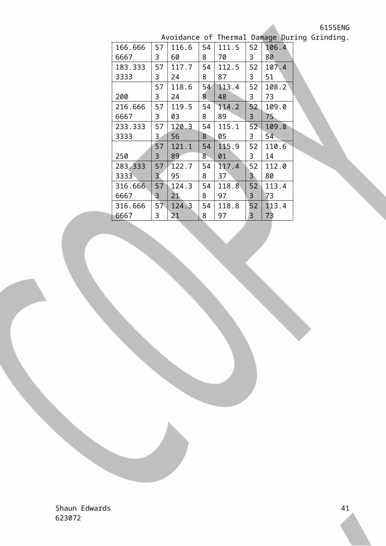
An abbreviation of the results of this thermal model is shown in table 4.4 below, the full results table
and a table showing the equations used are displayed in the appendices, appendix III. The results of
this model have been placed on a graph; this graph is visible in figure 4.2 below. The red points on
the experimental critical specific energy curve are the points where the workpiece was burnt during
the experiment; the hollow blue ones represent the experiments when burn did not occur.
Table 4.4 The results table showing the theoretical results calculated using the thermal model conceived by Rowe, Pettit Boyle et al. and generated using critical temperature values of 523K, 503K,
493K and 483K.
Vwϴm
ec* @ ϴm=573K
ϴm
ec* @ ϴm=548K
ϴm
ec* @ ϴm=523K
83.33333333
573 112.056
548 107.167
523 102.278
83.33333333
573 112.056
548 107.167
523 102.278
100573 112.973
548 108.044
523 103.115
116.6666667
573 113.929
548 108.958
523 103.987
133.3333333
573 114.898
548 109.885
523 104.872
150573 115.858
548 110.803
523 105.748
166.6666667
573 116.660
548 111.570
523 106.480
183.3333333
573 117.724
548 112.587
523 107.451
200573 118.624
548 113.448
523 108.273
216.6666667
573 119.503
548 114.289
523 109.075
233.3333333
573 120.356
548 115.105
523 109.854
250573 121.189
548 115.901
523 110.614
Shaun Edwards623072

6155ENGAvoidance of Thermal Damage During Grinding.
283.3333333
573 122.795
548 117.437
523 112.080
316.6666667
573 124.321
548 118.897
523 113.473
316.6666667
573 124.321
548 118.897
523 113.473
Shaun Edwards623072
30
6155ENGAvoidance of Thermal Damage During Grinding.
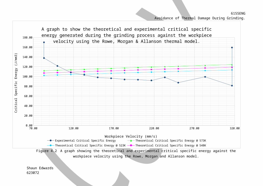
Figure 4.2 A graph showing the theoretical and experimental critical specific energy against the workpiece velocity using the Rowe, Morgan and Allanson model.
Shaun Edwards623072
70.00 120.00 170.00 220.00 270.00 320.000.00
20.00
40.00
60.00
80.00
100.00
120.00
140.00
160.00
180.00
A graph to show the theoretical and experimental critical specific energy generated during the grind-ing process against the workpiece velocity using the Rowe, Morgan & Allanson thermal model.
Experimental Critical Specific Energy Theoretical Critical Specific Energy @ 573KTheoretical Critical Specific Energy @ 523K Theoretical Critical Specific Energy @ 548K
Workpiece Velocity (mm/s)
Criti
cal S
pecifi
c Ene
rgy
(J/m
m3)

6155ENGAvoidance of Thermal Damage During Grinding.
5. Discussion.Using the thermal model first presented by Rowe, Petit, Boyle et al. it is possible for lines to be
plotted on the graph to determine at what critical specific energy burn occurs at different velocities.
When these lines are placed on the same graph as the experimental critical specific, it is possible to
determine the maximum temperature of the grinding wheel at a certain velocity. The workpiece used
was made of steel with a Rockwell hardness C of 61; this type of steel is thermally damaged at 523K.
When this temperature is plotted using the Rowe, Pettit, Boyle et al. model, as illustrated in figure
4.1, it is an under-estimation of what is actually occurring. When the experiment was run at 100
mm*s-1 the workpiece was thermally damaged; however according to the thermal model this
occurred at a temperature less than 523K. Through running the thermal model at different
temperatures, it appears that the temperature at which the thermal damage occurs at is between
483 and 493K. Temper colours, the visual sign of workpiece burn, could occur at a temperature as
low as 493K. Whilst according to this model it means that the last workpiece was burnt at a
temperature no lower than 483K, it doesn’t mean that with this thermal model thermal damage
couldn’t occur at a lower temperature. Due to the lack of intermediary points between that point
and the next point, burn could still occur at a lower critical specific energy. Though this seems at first
to be a problem, it could quickly be overcome. The material could become thermally damaged at a
temperature lower than even 492K. However more likely is the fact that this model isn’t conservative
enough; but even this doesn’t stop the thermal model being valid or unable to be used. Through
further testing and fine-tuning it is possible for the exact temperature that burn arises in this thermal
model to be found. This allows the thermal model to be used, whilst a hint of caution should still be
used when operating this model. It could be used in industry but would need to be heavily modified
and undergo lots of experimental testing first to guarantee that no thermal damage would occur
whilst this model is implemented.
In contrast the Rowe, Morgan and Allanson model is what appears to be an extremely conservative
model when plotted against the experimental critical specific energy as observed in figure 4.2.
According to figure 4.2, workpiece number 3 was thermally damaged at a temperature above 573K,
which is at least 50K higher than was thought. This means that this model would be a good model to
implement in industry as it means that if the critical specific grinding energy doesn’t go above this
line then it hasn’t been thermally damaged. The down side to this is the fact that it isn’t as efficient
as some companies may like, and therefore may mean that workpieces are discarded even if they
aren’t thermally damaged. This obviously loses the company money on two fronts, as there is an
Shaun Edwards623072

6155ENGAvoidance of Thermal Damage During Grinding.
unnecessary scrapping of perfectly good workpieces and wasting time by not effectively grinding to
it’s full potential.
Ignoring the two points when the wheel is dressed, the experimental data shows a steady and even
decline, however it does start to fluctuate and lose its stability towards the end. The earlier, higher
points can be equated to the grind wheel still being sharp from the it recently being dressed and it
deteriorates quickly as the grind wheel erodes rapidly. The fluctuation later on can be put down to
the fact that the grind wheel will be wearing and degrading over the course of the experiments.
Between points 4 and 10 the experimental data shows a good ‘trueness’. In contrast, accounting for
all of the points there appears to be a lack of ‘trueness’ but that is to be expected when taking into
consideration what was explained above so the experimental results show a good degree of accuracy
with what is expected.
Taking the temperature at which the onset of burn occurs for this type of metal to be 523K, the two
thermal models demonstrate poor precision. The Rowe, Pettit, Boyle et al. model states that the
temperature at which it occurs is at least 40K lower than the one that is generally accepted; however
if the workpiece can be burnt at a temperature as low as 493K then the difference is less than 10K.
Then again, the Rowe, Morgan and Allanson model suggests that the temperature that burn occurs is
at least 25K or more than the known temperature it occurs at. Through further testing an exact point
at which burn occurs could be established which would help state which model is more precise.
As shown from the first and last times the experiment was undertaken, dressing the grind wheel has
affected the critical specific energy needed to grind in comparison to the same workpiece velocity
when not recently dressed. This is a surprising result but can be easily explained; with sharper grains
and unclogged pores, a newly dressed grind wheel is a much more effective grinding mechanism than
one with dull clogged up pores. However no change is made in the CNC programming to account for
this new sharpness and ease of grinding. So when the freshly dressed grind wheel is first employed, it
cuts through the workpiece too quickly; this drives the critical specific energy up causing the
workpiece to be thermally damaged. This could be overcome by better programming of the CNC to
allow for the new ease of grinding. If the in feed rate is increased this could overcome this problem
as it would increase the amount of the workpiece ground per second thus giving it more to cut
through. However in practice this may not work, it will more than likely also increase the power
consumed and thus raising the critical specific energy by more than the in feed rate lowers it.
Another idea would be to increase the speed of the grind wheel, although this wouldn’t do much to
the experimental critical specific energy; it would increase the energy needed to thermally damage
the workpiece using both models. The problem with this method is that it doesn’t increase it enough
Shaun Edwards623072
33
6155ENGAvoidance of Thermal Damage During Grinding.
to overtake the energy generated during a pass with the newly dressed grind wheel. So if both
strategies were combined then this problem could be easily overcome; by cleverly programming the
computer, a button could be installed to easily switch between the normal grinding parameters and
those needed to grind a freshly dressed grind wheel without burning the workpiece.
Neither thermal model takes into account how properly the partition of thermal energy into each
heat sync. Although coolant was used and sparks were created, very little of this, if any at all, is
accounted for in the equation. Even a simple calculation now could establish that around 5% of the
total energy accumulates in the swarf; another 5% enters the coolant and between 10 to 20% flows
into the grind wheel. Even at a conservative estimate, around 70% of the total energy generated is
passed onto the workpiece, yet this isn’t the case in either model. Advances recently have
established ways of calculating how much energy is imparted into the chips generated during the
process. By using the fact that the swarf is hot enough to cause an exothermic reaction that turns
the chips into sparks, it is possible to work backwards from the known temperature at which these
sparks are generated to calculate how much energy has been inputted into the swarf and can be
subtracted from the total energy calculated. The same sort of principle could be applied to the
coolant if the temperature of the fluid is measured before it flows into the grinding zone and as it
leave it too. Then the change in temperature and the specific heat capacity as well as the mass the
flow the total energy gained by the fluid could be calculated and subtracted from the total energy
generated.
Although the experimental data was from a previous experiment, this data was recorded by a highly
reliable and experienced source in Andy Pettit. Having written and contributed to many academic
papers on the subject of grinding, Andy Pettit has lots of knowledge when it comes to recording data
from grinding experiments. However just because he is a reliable source when it comes to the
recording the data, it does not stop there being systematic and random errors featuring in the data.
Systematic error in this experiment could stem from the equipment not being calibrated properly, for
example the dynamometer fitted to the machine or the distance between the edge of the grind
wheel and the centre of the headstock. This error would be constant throughout the experiment if
not altered and would be amplified through the calculations carried out, giving a slightly noticeable
problem at the end. There will also be a quantitative systematic error involved in the experiment that
could stem from the temperatures encountered whilst grinding. These temperatures, if they get too
high, could affect some of the recording apparatus and cause them to give out readings that are
slightly out. If the machine were run for a long time, it would increase the likelihood of those
temperatures being generated and consequently reached. Random errors are also present in this
Shaun Edwards623072
34
6155ENGAvoidance of Thermal Damage During Grinding.
experiment; this could be from the dynamometer not being able to keep up with the fluctuations in
the power changes. This may lead to the maximum power being missed by the investigator as it’s not
a linear, constant recording, instead it lags behind and jumps around sporadically making it tough to
get an exact reading.
Also certain assumptions have been made with aspects of the experiment, some of these aspects will
be acceptable with no impact, however some assumptions have a slight impact but cannot be
helped. It is assumed that steady state conditions are applicable as well as constant atmospheric
conditions i.e. continuous room temperature and air pressure. These assumptions have very little
impact on the equations, it just allows all of the total energy to flow into the 4 heat syncs and not the
atmosphere. With respect to the equipment used, some of the assumptions made are constant
density through the workpiece and the grind wheel, this guarantees that the thermal conductivity
and diffusivity is constant throughout. In the real life this isn’t the case, this could have an impact on
the calculations as both parameters are crucial to both models. Then again, a big enough fluctuation
couldn’t occur as there would be something drastically wrong and the machine wouldn’t function
properly. So although this may not be the most precise assumption, it is precise enough to work in
these models. Another set of assumptions are to do with the cooling fluid, one that all of the fluid
enters the contact zone and two is that it doesn’t get hot enough for fluid film boiling to occur. These
two are crucial, the first one as this could have an impact if proved wrong by changing the quantity of
energy flowing into each heat sync and the second, as discussed earlier, causes the workpiece to be
burnt a lot easier. This also leads to the fact that if the energy entering the grinding swarf was
accounted for properly, an assumption made would be that the energy entering it is at the right
levels to cause the grinding swarf to exothermically react and that temperature is a constant and
known.
Using all that has been learnt, an adaptive control system can be incorporated into the grinding
machine using the thermal models to guarantee that thermal damage is avoided as well as speeding
up and making the process more efficient, thus reducing costs. This strategy can be easily
programmed into the CNC system and could cost very little if implemented correctly. If a
dynamometer was fitted and then linked up to the control system, it could measure the power being
consumed at set intervals. This power could then be fed through the equations to calculate the
critical specific energy, if that energy gets too close to the agreed line on the pre-set thermal model it
could alter the grinding parameters to lower the power being consumed. This allows for the optimal
conditions to be exercised as well as guaranteeing the workpiece isn’t burnt, thus improving the
Shaun Edwards623072
35
6155ENGAvoidance of Thermal Damage During Grinding.
speed and time it takes to grind a workpiece leading to the lowering the cost of manufacturing each
unit.
Shaun Edwards623072
36

6155ENGAvoidance of Thermal Damage During Grinding.
6. Conclusion.This work has introduced the importance of burn detection in the grinding process and prevention
using thermal models to create safe grinding parameters. Whilst both models are not what was
expected in terms of precision to the real life data recorded, one of the models could be used
straight away in industry with very little modification. The Rowe, Morgan and Allanson model is a
moderate model that is cautious in its application; this works well when placed into industry, as it
means there is a very small chance that a work piece would be burnt if this model was used. This
reduces the risk of the workpiece failing in service; which, ultimately, is the primary objective when
machining such an important workpiece. The Rowe, Pettit, Boyle et al. model is an aggressive model
which has the advantage of being much more efficient compared to the other model. This model
would be harder to implement in industry, however with further testing and improvements made to
the energy partitioning ratio, it could be implemented safely using in process control and
measurement system.
The results are appropriate for what was expected from them and especially the middle few results
show a strong correlation and expected pattern. It illustrated how wheel wear can affect the grinding
process and how it is of vital importance to modify the grinding setup if the grind wheel has recently
been dressed. Several assumptions have been made though these are needed and don’t affect the
outcome enough to be examined further.
Further research that could be carried out is research into the energy partition ratio and the effect
that that could have on the critical specific energy and the thermal models. Also looking into
improving the efficiency of the grinding process as well as the practical application of the thermal
models in industry and improving them. Additional work will also look into more thermal models and
carry out testing to gather the correct data to be inputted into these models. These models can then
be compared with the ones already found and critically appraised and improvements and practical
applications can then be explored.
Shaun Edwards623072
37
6155ENGAvoidance of Thermal Damage During Grinding.
Appendix.
Appendix I
ThermalConductivity= Wm∗K
≡J
mm×K ×s
ec¿=K ×( mm
mm2
s×mms )
0.5
×
Jmm×K×s
mm≡K ×( mmmm3
s2)0.5
×( Jmm×K ×s
×1mm )
≡K1×(mm1 ×
s2
mm2 )0.5
×J
K×s×mm2≡(mm×s
2
mm3 )0.5
×J× K
K ×s×mm2≡√ s2
mm2×
J
s×mm2
≡smm
×J
s×mm2≡
s×J
s×mm3≡
J
mm3≡J ×mm−3
Shaun Edwards623072
38

6155ENGAvoidance of Thermal Damage During Grinding.
Appendix II
Shaun Edwards623072
Work Piece no. Vw
Dress Pn PL
Burn ds dW lW Vf Vs Pg Zw Us Vw a de
1 5 Y 816 7344 Y 441 43.347 47 0.0120 33000 138.89 0.8171 169.99 83.33 0.0196 39.4682 5 N 819 6108 Y 441 43.347 47 0.0120 33000 112.53 0.8171 137.73 83.33 0.0196 39.4683 6 N 816 5484 Y 441 43.348 47 0.0120 33000 99.32 0.8171 121.55 100.00 0.0163 39.4684 7 N 816 4968 N 441 43.351 47 0.0120 33000 88.34 0.8171 108.11 116.67 0.0140 39.4715 8 N 813 4785 N 441 43.35 47 0.0120 33000 84.51 0.8171 103.42 133.33 0.0123 39.4706 9 N 819 4590 N 441 43.35 47 0.0120 33000 80.23 0.8171 98.19 150.00 0.0109 39.4707 10 N 813 4521 N 441 43.451 47 0.0120 33000 78.89 0.8190 96.33 166.67 0.0098 39.5548 11 N 816 4422 N 441 43.351 47 0.0120 33000 76.72 0.8171 93.89 183.33 0.0089 39.4719 12 N 819 4407 N 441 43.352 47 0.0120 33000 76.34 0.8172 93.42 200.00 0.0082 39.472
10 13 N 813 4344 N 441 43.352 47 0.0120 33000 75.13 0.8172 91.94 216.67 0.0075 39.47211 14 N 813 4587 N 441 43.354 47 0.0120 33000 80.30 0.8172 98.26 233.33 0.0070 39.47312 15 N 810 4167 N 441 43.355 47 0.0120 33000 71.43 0.8172 87.40 250.00 0.0065 39.47413 17 N 810 4623 N 441 43.355 47 0.0120 33000 81.13 0.8172 99.27 283.33 0.0058 39.47414 19 N 816 3936 N 441 43.356 47 0.0120 33000 66.38 0.8172 81.23 316.67 0.0052 39.47515 19 Y 810 6930 Y 441 43.356 47 0.0120 33000 130.21 0.8172 159.33 316.67 0.0052 39.475
6155ENGAvoidance of Thermal Damage During Grinding.
Shaun Edwards623072
Work Piece no. Lg Le αw αs λs λw 1/R R ϴm ec* ϴm
ec* @ ϴm=503K ϴm
ec* @ ϴm=493K ϴm
ec* @ ϴm=483K
10.88
0 2.639 14.7 1.15 0.55 53.7 1.729 0.578 523 129.560 503 124.605 493 122.128 483 119.651
20.88
0 2.639 14.7 1.15 0.55 53.7 1.729 0.578 523 129.560 503 124.605 493 122.128 483 119.651
30.80
3 2.409 14.7 1.15 0.55 53.7 1.665 0.601 523 130.620 503 125.625 493 123.127 483 120.630
40.74
4 2.231 14.7 1.15 0.55 53.7 1.616 0.619 523 131.724 503 126.687 493 124.169 483 121.650
50.69
6 2.087 14.7 1.15 0.55 53.7 1.576 0.634 523 132.845 503 127.765 493 125.225 483 122.685
60.65
6 1.967 14.7 1.15 0.55 53.7 1.543 0.648 523 133.955 503 128.832 493 126.271 483 123.710
70.62
3 1.870 14.7 1.15 0.55 53.7 1.515 0.660 523 134.882 503 129.724 493 127.145 483 124.566
80.59
3 1.780 14.7 1.15 0.55 53.7 1.491 0.671 523 136.112 503 130.907 493 128.305 483 125.702
90.56
8 1.704 14.7 1.15 0.55 53.7 1.470 0.680 523 137.153 503 131.908 493 129.286 483 126.663
100.54
6 1.637 14.7 1.15 0.55 53.7 1.452 0.689 523 138.169 503 132.885 493 130.243 483 127.602
110.52
6 1.577 14.7 1.15 0.55 53.7 1.435 0.697 523 139.156 503 133.834 493 131.174 483 128.513
120.50
8 1.524 14.7 1.15 0.55 53.7 1.421 0.704 523 140.119 503 134.760 493 132.081 483 129.402
130.47
7 1.432 14.7 1.15 0.55 53.7 1.395 0.717 523 141.975 503 136.546 493 133.831 483 131.117
140.45
1 1.354 14.7 1.15 0.55 53.7 1.374 0.728 523 143.740 503 138.243 493 135.495 483 132.747
150.45
1 1.354 14.7 1.15 0.55 53.7 1.374 0.728 523 143.740 503 138.243 493 135.495 483 132.74740
6155ENGAvoidance of Thermal Damage During Grinding.
Shaun Edwards623072
41
6155ENGAvoidance of Thermal Damage During Grinding.
Shaun Edwards623072
42

6155ENGAvoidance of Thermal Damage During Grinding.
Appendix IIIWork Piece no. Vw Dress Pn PL Burn ds dW lW Vf Vs Pg Zw Us Vw a de Lg
1 5 Y 816 7344 Y 441 43.347 47 0.0120 33000 138.89 0.8171 169.99 83.33 0.0196 39.468 0.8802 5 N 819 6108 Y 441 43.347 47 0.0120 33000 112.53 0.8171 137.73 83.33 0.0196 39.468 0.8803 6 N 816 5484 Y 441 43.348 47 0.0120 33000 99.32 0.8171 121.55 100.00 0.0163 39.468 0.8034 7 N 816 4968 N 441 43.351 47 0.0120 33000 88.34 0.8171 108.11 116.67 0.0140 39.471 0.7445 8 N 813 4785 N 441 43.35 47 0.0120 33000 84.51 0.8171 103.42 133.33 0.0123 39.470 0.6966 9 N 819 4590 N 441 43.35 47 0.0120 33000 80.23 0.8171 98.19 150.00 0.0109 39.470 0.6567 10 N 813 4521 N 441 43.451 47 0.0120 33000 78.89 0.8190 96.33 166.67 0.0098 39.554 0.6238 11 N 816 4422 N 441 43.351 47 0.0120 33000 76.72 0.8171 93.89 183.33 0.0089 39.471 0.5939 12 N 819 4407 N 441 43.352 47 0.0120 33000 76.34 0.8172 93.42 200.00 0.0082 39.472 0.568
10 13 N 813 4344 N 441 43.352 47 0.0120 33000 75.13 0.8172 91.94 216.67 0.0075 39.472 0.54611 14 N 813 4587 N 441 43.354 47 0.0120 33000 80.30 0.8172 98.26 233.33 0.0070 39.473 0.52612 15 N 810 4167 N 441 43.355 47 0.0120 33000 71.43 0.8172 87.40 250.00 0.0065 39.474 0.50813 17 N 810 4623 N 441 43.355 47 0.0120 33000 81.13 0.8172 99.27 283.33 0.0058 39.474 0.47714 19 N 816 3936 N 441 43.356 47 0.0120 33000 66.38 0.8172 81.23 316.67 0.0052 39.475 0.45115 19 Y 810 6930 Y 441 43.356 47 0.0120 33000 130.21 0.8172 159.33 316.67 0.0052 39.475 0.451
Shaun Edwards623072
43
6155ENGAvoidance of Thermal Damage During Grinding.
Le αw αs λs λw 1/R R ϴmec* @ ϴm=573K ϴm
ec* @ ϴm=548K ϴm
ec* @ ϴm=523K
2.639 14.7 1.15 0.55 53.7 1.729 0.57857
3 112.056 548 107.16752
3 102.278
2.639 14.7 1.15 0.55 53.7 1.729 0.57857
3 112.056 548 107.16752
3 102.278
2.409 14.7 1.15 0.55 53.7 1.665 0.60157
3 112.973 548 108.04452
3 103.115
2.231 14.7 1.15 0.55 53.7 1.616 0.61957
3 113.929 548 108.95852
3 103.987
2.087 14.7 1.15 0.55 53.7 1.576 0.63457
3 114.898 548 109.88552
3 104.872
1.967 14.7 1.15 0.55 53.7 1.543 0.64857
3 115.858 548 110.80352
3 105.748
1.870 14.7 1.15 0.55 53.7 1.515 0.66057
3 116.660 548 111.57052
3 106.480
1.780 14.7 1.15 0.55 53.7 1.491 0.67157
3 117.724 548 112.58752
3 107.451
1.704 14.7 1.15 0.55 53.7 1.470 0.68057
3 118.624 548 113.44852
3 108.273
1.637 14.7 1.15 0.55 53.7 1.452 0.68957
3 119.503 548 114.28952
3 109.075
1.577 14.7 1.15 0.55 53.7 1.435 0.69757
3 120.356 548 115.10552
3 109.854
1.524 14.7 1.15 0.55 53.7 1.421 0.70457
3 121.189 548 115.90152
3 110.614
1.432 14.7 1.15 0.55 53.7 1.395 0.71757
3 122.795 548 117.43752
3 112.080
1.354 14.7 1.15 0.55 53.7 1.374 0.72857
3 124.321 548 118.89752
3 113.473
1.354 14.7 1.15 0.55 53.7 1.374 0.72857
3 124.321 548 118.89752
3 113.473
Shaun Edwards623072
6155ENGAvoidance of Thermal Damage During Grinding.
Shaun Edwards623072
6155ENGAvoidance of Thermal Damage During Grinding.
Shaun Edwards623072
6155ENGAvoidance of Thermal Damage During Grinding.
References
Airbus. (2014, July 4). Dimensions & Key Data of the A380 Passenger Jet. Retrieved November 5,
2014, from Airbus: http://www.airbus.com/aircraftfamilies/passengeraircraft/a380family/
specifications/
Andrew, C., Howes, T. D., & Pearce, T. R. (1985). Creep Feed Grinding. London: Holt, Rinehart and
Winston Ltd.
Boothroyd, G., & Knight, W. A. (1989). Fudamentals of Machining and Machine Tools (Second ed.).
New York: Marcel Dekker Ltd.
British Standards. (1994). BS ISO 5725-1:1994 Accuracy (trueness and precision) of measurement
methods and results. London: BSI Publications.
Chen, X., & Griffin, J. (2008, September 26). Grinding Burn and Chatter Classification Using Genetic
Prgramming. (T. Kuriyagawa, L. Zhou, J. Yan, & N. Yoshihara, Eds.) Key Engineering Materials:
Advances in Abrasive Technology XI, pp. 90 - 95.
Chen, X., & Griffin, J. (2009). Grinding burn and chatter classification using genetic programming. 11th
International Symposium on Advances in Abrasive Technology. (pp. 90-95). Zurich: Trans Tech
Publications Ltd.
Des Reisseaux, N. R., & Zerkle, R. D. (1970). Temperaturs in Semi-Infinte and Cylindrical Bodies
Subject to Moving Heat Sources and Surface Cooling. Journal of Heat Transfer, 92, 456-464.
Farlex. (2010, February 23). The Grinding Machine. Retrieved November 8, 2014, from The Free
Dictionary: http://encyclopedia2.thefreedictionary.com/Grinding+Machine
Hahn, R. S. (1962). On The Nature Of The Grinding Process. The 3rd Internationa; Machine Tool
Design Research Conference (pp. 129-154). Birmingham: Oxford University Press.
Howes, T. D., Neaily, K., & Harrison, A. J. (1987). Fluid Film Boiling in Shallow-Cut Grinidng. The
International Academy for Production Engineering Annals, 36(1), 223-226.
Jaeger, J. C. (1942). Moving Sources of Heat and the Temperature at Sliding Contacts. Proceedings of
the Royal Society of New South Wales. 76, pp. 203-224. Sydney: Royal Society of New South
Wales.
Shaun Edwards623072
6155ENGAvoidance of Thermal Damage During Grinding.
Makino, H., Suto, & Fokushima. (1966). An Experimental Investigation of the Grinding Process.
Japanese Mechanical Laboratory. Tokyo: Japanese Society of Mechanical Engineers.
Malkin, S., & Cook, N. H. (1971, November). The Wear of the Grinding Wheels Part 2 - Fracture Wear.
The American Journal for Industrial Engineering, 1129-1133.
Marinescu, I. D., Rowe, W. B., Dimitrov, B., & Inasaki, I. (2004). Tribology of Abrasive Machining
Processes (1st ed.). New York: William Andrew Publishing.
Nathan, R. D., Vijayaraghavan, L., & Krishnamurthy , R. (1999, June 30). In-process Monitoring of
Grinding Burn in the Cylindrical Grinding of Steel. Journal of Materials Processing Technology,
91(1-3), 37-42.
Outwater, J. C., & Shaw, M. C. (1952). Surface Temperatures in Grinding. New York: The American
Society for Mechanical Engineers.
Qi, H. S., Mills, B., & Rowe, W. B. (1994, March 31). An analysis of real contact length in abrasive
machining processes using contact mechanics. Wear., 176(1), 137-141.
Rowe, W. B. (2009). Principles of Modern Grinding Technology. New York: William Andrew Publishing.
Rowe, W. B., Black, S. C., Mills, B., Morgan, M. N., & Qi, H. S. (1997, May 8). Grinding Temperatures
and Energy Partitioning. The Royal Society Proceedings: Mathematical, Physical and
Engineering Sciences, 453(1960), 1083 - 1104.
Rowe, W. B., Morgan, M. N., & Allanson, D. A. (1991, January 16). An Advance in the Modelling of
Thermal Effects in the Grinding Process. Annals of the CIRP, 40(1), 339-342.
Rowe, W. B., Pettit, J. A., Boyle, A., & Moruzzi, J. L. (1988). Avoidance of Thermal Damage in Grinding
and Prediction of the Damage Threshold. Manufacturing Technology, 37(1), 327–330.
Shaw, M. C. (1996). Principles of Abrasive Processing. Oxford: Oxford University Press.
Slamon, S. C. (1992). Modern Grinding Process Technology. New York: McGraw-Hill inc.
Tawakoli, T. (1990). High Energy Deep Grinding. (C. G. Barrett, Trans.) London: Mechanical
Engineering Publications Ltd.
Shaun Edwards623072
48