AVM 20 - Anthem · 8. Ventilation – Slots and openings in the cabinet are provided for...
84
AVM 20 OPERATING MANUAL UPDATES: www.anthemAV.com SOFTWARE VERSION 2.1x ™
Transcript of AVM 20 - Anthem · 8. Ventilation – Slots and openings in the cabinet are provided for...
AVM 20OPERATING MANUAL
UPDATES: www.anthemAV.com
S O F T W A R E V E R S I O N 2 . 1 x
™

SAFETY PRECAUTIONSREAD THIS SECTION CAREFULLY BEFORE PROCEEDING!
The lightning flash with arrowpoint within an equilateral trianglewarns of the presence of uninsulated “dangerous voltage” withinthe product’s enclosure that may be of sufficient magnitude toconstitute a risk of electric shock to persons.
The exclamation point within an equilateral triangle warns usersof the presence of important operating and maintenance (servicing)instructions in the literature accompanying the appliance.
WARNING: TO REDUCE THE RISK OF FIRE OR ELECTRIC SHOCK, DO NOT EXPOSE THIS PRODUCT TO RAIN OR MOISTURE.
CAUTION: TO PREVENT ELECTRIC SHOCK, MATCH WIDE BLADE OF PLUG TO WIDE SLOT, FULLY INSERT.
CAUTION: FOR CONTINUED PROTECTION AGAINST RISK OF FIRE, REPLACE THE FUSE ONLY WITH THE SAMEAMPERAGE AND VOLTAGE TYPE. REFER REPLACEMENT TO QUALIFIED SERVICE PERSONNEL.
WARNING: UNIT MAY BECOME HOT. ALWAYS PROVIDE ADEQUATE VENTILATION TO ALLOW FOR COOLING. DO NOT PLACENEAR A HEAT SOURCE, OR IN SPACES THAT CAN RESTRICT VENTILATION.
IMPORTANT SAFETY INSTRUCTIONS
WARNING: TO REDUCE THE RISK OF ELECTRIC SHOCK,DO NOT REMOVE COVER (OR BACK). NO USER-SERVICEABLE PARTS INSIDE. REFER SERVICING TOQUALIFIED SERVICE PERSONNEL.
RISK OF ELECTRIC SHOCK DO NOT OPEN
WARNING
1. Read Instructions – All the safety and operating instructions should be read before the product is operated.
2. Retain Instructions – The safety and operating instructions should be retained for future reference.
3. Heed Warnings – All warnings on the product and in the operating instructions should be adhered to.
4. Follow Instructions – All operating and use instructions should be followed.
5. Cleaning – Unplug this product from the wall outlet before cleaning. Do not use liquid cleaners or aerosolcleaners. Use a damp, soft cloth for cleaning.
6. Water and Moisture – Do not use this product near water – for example, near a bath tub, wash bowl, kitchensink, or laundry tub; in a wet basement; or near a swimming pool; and the like.
7. Accessories – Do not place this product on an unstable cart, stand, tripod, bracket, or table. The product mayfall, causing serious injury to a child or adult, and serious damage to the product. Use only with a cart, stand,tripod, bracket, or table recommended by the manufacturer, or sold with the product. Any mounting of the productshould follow manufacturer’s instructions, and should use a mounting accessory recommended by the manufacturer.

8. Ventilation – Slots and openings in the cabinet are provided for ventilation and to ensure reliable operationof the product and to protect it from overheating, and these openings must not be blocked or covered. The openingsshould never be blocked by placing the product on a bed, sofa, rug, or other similar surface. This productshould not be placed in a built-in installation such as a bookcase or rack unless proper ventilation is provided orthe manufacturer’s instructions have been adhered to.
9. Power Sources – This product should be operated only from the type of power source indicated on the markinglabel. If you are not sure of the type of power supply to your home, consult your product dealer or local powercompany. For products intended to operate from battery power, or other sources, refer to the operating instructions.
10. Grounding and Polarization – This product may be equipped with a polarized alternating-current line plug (a plughaving one blade wider than the other). This plug will fit into the power outlet only one way. This is a safety feature.If you are unable to insert the plug fully into the outlet, try reversing the plug. If the plug should still fail to fit,contact your electrician to replace your obsolete outlet. Do not defeat the safety purpose of the polarized plug.
11. Power-cord Protection – Power-supply cords should be routed so that they are not likely to be walked on orpinched by items placed upon or against them, paying particular attention to cords at plugs, conveniencereceptacles, and the point where they exit from the product.
12. Outdoor Antenna Grounding – If an outside antenna or cable system is connected to the product, be sure theantenna or cable system is grounded so as to provide some protection against voltage surges and built-upstatic charges. Article 810 of the National Electrical Code, ANSI/NFPA 70, provides information with regard tothe proper grounding of the mast and supporting structure, grounding of the lead-in wire to an antenna–discharge unit, size of grounding conductors, location of antenna-discharge unit, connection to groundingelectrodes, and requirements for the grounding electrode.
13. Lightning – For added protection for this product during a lightning storm, or when it is left unattended andunused for long periods of time, unplug it from the wall outlet and disconnect the antenna or cable systems.This will prevent damage to the product due to lightning and power-line surges.
14. Power Lines – An outside antenna system should not be located in the vicinity of overhead power lines orother electric light or power circuits, or where it can fall into such power lines or circuits. When installing anoutside antenna system, extreme care should be taken to keep from touching such power lines or circuits ascontact with them might be fatal.
Antenna Lead-In Wire
Antenna-Discharge Unit (NEC Section 810-20)
Grounding Conductors (NEC Section 810-21)
Power Service GroundingElectronic System
(NEC ART 250. Part H) NEC-National Electrical Code
Electrical Service Equiptment
Ground Clamp
Ground Clamps
S2898A

Copyright© Anthem™/Sonic Frontiers International. All rights reserved. The information contained herein may not be reproducedin whole or in part without our express written permission.
ANTHEM™ is a trademark of Sonic Frontiers International. All other trademarks are the property of their respective owners.
Anthem™/Sonic Frontiers International reserves the right to change specifications and/or features without notice as designimprovements are incorporated.
Motorola name and logo are registered trademarks of Motorola, Inc.
PHASTLINK™ is a trade mark of PHAST Corporation.
Manufactured under license from Dolby Laboratories. “Dolby”, “Pro Logic”, “AC-3”, “Surround EX”, and the double-D symbol are trademarks of Dolby Laboratories.
“DTS”, “DTS-ES Extended Surround”, “DTS 96/24”, and “Neo:6” are trademarks of Digital Theater Systems, Inc.
Manufactured under license from THX Ltd. U.S. patent numbers 5,043,970; 5,189,703; and/or 5,222,059. European patentnumber 0323830. Other U.S. and foreign patents pending. Ultra2 and THX are trademarks or registered trademarks of THX Ltd.
Lucasfilm is a trademark of Lucasfilm Ltd. Surround EX is a trademark of Dolby Laboratories. Used under authorization.
15. Overloading – Do not overload wall outlets, extension cords, or integral convenience receptacles as this canresult in a risk of fire or electric shock.
16. Object and Liquid Entry – Never push objects of any kind through openings as they may touch dangerous voltagepoints or short-out parts that could result in a fire or electric shock. Never spill liquid of any kind on this product.
17. Servicing – Do not attempt to service this product yourself, as opening or removing covers may expose youto dangerous voltage or other hazards. Refer all servicing to qualified service personnel.
18. Damage Requiring Service – Unplug this product from the wall outlet and refer servicing to qualified personnelunder the following conditions:
• When power-supply cord or plug is damaged.
• If liquid has been spilled, or objects have fallen into the product.
• If the product has been exposed to rain or water.
• If the product does not operate normally by following the operating instructions. Adjust only those controlsthat are covered by the operating instructions as an improper adjustment of other controls may result in damageand will require extensive work by a qualified technician to restore the product to its normal operation.
• If the product has been dropped or damaged in any way.
• If the product exhibits a distinct change in performance – this indicates a need for service.
19. Replacement Parts – When replacement parts are required, be sure the technician has used replacementparts specified by the manufacturer or have the same characteristics as the original part. Unauthorizedsubstitutions may result in fire, electric shock, or other hazards.
20. Safety Check – Upon completion of any service or repairs to this product, ask the service technician to performsafety checks to determine that the product is in proper operating condition.
21. Heat – The product should be situated away from heat sources such as radiators, heat registers, stoves, orother products (including amplifiers) that produce heat.

SECTION PAGE
1. INTRODUCTION 1
1 Receiving and Unpacking the AVM 20 . . . . . . . . . . . . . . . . . . . . . . . . . . . . . . . . . . . . . . . . . . . . . . . . . 1
1.1 Packing List . . . . . . . . . . . . . . . . . . . . . . . . . . . . . . . . . . . . . . . . . . . . . . . . . . . . . . . . . . . . . . . . . . . . . . . . 1
1.2 Important Safety Instructions . . . . . . . . . . . . . . . . . . . . . . . . . . . . . . . . . . . . . . . . . . . . . . . . . . . . . . . . . 11.2.1 Before Operating Your AVM 20 11.2.2 Supply Power Requirements 21.2.3 In-Use Notices 2
1.3 Packing Materials . . . . . . . . . . . . . . . . . . . . . . . . . . . . . . . . . . . . . . . . . . . . . . . . . . . . . . . . . . . . . . . . . . 2
2. QUICK START 3
2.1 Quick Start Guide . . . . . . . . . . . . . . . . . . . . . . . . . . . . . . . . . . . . . . . . . . . . . . . . . . . . . . . . . . . . . . . . . . . 3
2.2 Connector Diagrams and Descriptions . . . . . . . . . . . . . . . . . . . . . . . . . . . . . . . . . . . . . . . . . . . . . . . . 42.2.1 CD Player to AVM 20 52.2.2 DVD Player and TV to AVM 20 62.2.3 VCR and TV to AVM 20 72.2.4 AVM 20 to Amplifier and Powered Subwoofer (RCA) 82.2.5 AVM 20 to Amplifiers and Powered Subwoofer (XLR) 9
2.3 Speaker Placement . . . . . . . . . . . . . . . . . . . . . . . . . . . . . . . . . . . . . . . . . . . . . . . . . . . . . . . . . . . . . . . 10
3. PANELS / DISPLAYS / REMOTE LAYOUT 11
3.1 Front Panel Layout . . . . . . . . . . . . . . . . . . . . . . . . . . . . . . . . . . . . . . . . . . . . . . . . . . . . . . . . . . . . . . . . . 11
3.2 Front Panel Display . . . . . . . . . . . . . . . . . . . . . . . . . . . . . . . . . . . . . . . . . . . . . . . . . . . . . . . . . . . . . . . . 12
3.3 Rear Panel Layout . . . . . . . . . . . . . . . . . . . . . . . . . . . . . . . . . . . . . . . . . . . . . . . . . . . . . . . . . . . . . . . . . . 13
3.4 Remote Control Layout . . . . . . . . . . . . . . . . . . . . . . . . . . . . . . . . . . . . . . . . . . . . . . . . . . . . . . . . . . . . . 14
4. CONNECTIONS 15
4.1 Connecting Power To The AVM 20 . . . . . . . . . . . . . . . . . . . . . . . . . . . . . . . . . . . . . . . . . . . . . . . . . . . 15
4.2 Audio Connections . . . . . . . . . . . . . . . . . . . . . . . . . . . . . . . . . . . . . . . . . . . . . . . . . . . . . . . . . . . . . . . . 154.2.1 Digital Audio Inputs and Outputs . . . . . . . . . . . . . . . . . . . . . . . . . . . . . . . . . . . . . . . . . . . 154.2.2 Analog Audio Inputs 154.2.3 Left / Right Analog Audio Inputs 164.2.4 2-Ch Balanced and 6-Ch Single-Ended Audio Inputs 164.2.5 Analog Audio Outputs 16
4.3 Video Connections . . . . . . . . . . . . . . . . . . . . . . . . . . . . . . . . . . . . . . . . . . . . . . . . . . . . . . . . . . . . . . . . . 17Composite Video 17S-Video 17Component Video 17
4.4 Powered I.R. (Infra Red) Receivers . . . . . . . . . . . . . . . . . . . . . . . . . . . . . . . . . . . . . . . . . . . . . . . . . . . . 19
4.5 I.R. (Infra Red) Emitters. . . . . . . . . . . . . . . . . . . . . . . . . . . . . . . . . . . . . . . . . . . . . . . . . . . . . . . . . . . . . . 19
4.6 Relay Triggers . . . . . . . . . . . . . . . . . . . . . . . . . . . . . . . . . . . . . . . . . . . . . . . . . . . . . . . . . . . . . . . . . . . . . 19
4.7 FM • AM Antennas . . . . . . . . . . . . . . . . . . . . . . . . . . . . . . . . . . . . . . . . . . . . . . . . . . . . . . . . . . . . . . . . . . 19
TABLE of CONTENTS

5. FRONT PANEL OPERATION 20
5.1 Power On / Off . . . . . . . . . . . . . . . . . . . . . . . . . . . . . . . . . . . . . . . . . . . . . . . . . . . . . . . . . . . . . . . . . . . . 20
5.2 Path Selection . . . . . . . . . . . . . . . . . . . . . . . . . . . . . . . . . . . . . . . . . . . . . . . . . . . . . . . . . . . . . . . . . . . . . 205.2.1 Copying the MAIN Path to ZONE2, ZONE3, or RECORD 21
Down-Mixing to 2-Channel Stereo 21
5.3 Master Control Knob . . . . . . . . . . . . . . . . . . . . . . . . . . . . . . . . . . . . . . . . . . . . . . . . . . . . . . . . . . . . . . . . 21
5.4 Source Selection. . . . . . . . . . . . . . . . . . . . . . . . . . . . . . . . . . . . . . . . . . . . . . . . . . . . . . . . . . . . . . . . . . . 215.4.1 6-Channel S/E Input 215.4.2 FM • AM Tuner 22
Manual Tuning 22Automatic Tuning 22Presets 22ST / HiB / M 22
5.4.3 Simulcast 22
5.5 Volume Control . . . . . . . . . . . . . . . . . . . . . . . . . . . . . . . . . . . . . . . . . . . . . . . . . . . . . . . . . . . . . . . . . . . . 23Dialog Normalization 23Mute 23
5.6 Surround Mode Level . . . . . . . . . . . . . . . . . . . . . . . . . . . . . . . . . . . . . . . . . . . . . . . . . . . . . . . . . . . . . . . 23
5.7 Bass / Treble / Balance . . . . . . . . . . . . . . . . . . . . . . . . . . . . . . . . . . . . . . . . . . . . . . . . . . . . . . . . . . . . . 24Tone Bypass 24
5.8 Surround Modes . . . . . . . . . . . . . . . . . . . . . . . . . . . . . . . . . . . . . . . . . . . . . . . . . . . . . . . . . . . . . . . . . . . 245.8.1 AnthemLogic™ 255.8.2 Dolby Digital-2.0 255.8.3 Surround Modes for Stereo Source Material 265.8.4 Dolby Digital EX 275.8.5 DTS-ES 275.8.6 THX Ultra2 / THX Surround EX 275.8.7 Modes and THX Operation for Stereo Program Material 315.8.8 Modes and THX Operation for Dolby Digital 5.1 Program Material 325.8.9 Modes and THX Operation for DTS program Material 335.8.10 Dynamics 34
5.9 Front Panel Display. . . . . . . . . . . . . . . . . . . . . . . . . . . . . . . . . . . . . . . . . . . . . . . . . . . . . . . . . . . . . . . . . 34
5.10 Status / Setup. . . . . . . . . . . . . . . . . . . . . . . . . . . . . . . . . . . . . . . . . . . . . . . . . . . . . . . . . . . . . . . . . . . . . . 34
6. REMOTE CONTROL OPERATION 35
6.1 Powering the AVM 20 ON and OFF . . . . . . . . . . . . . . . . . . . . . . . . . . . . . . . . . . . . . . . . . . . . . . . . . . . . 35
6.2 Path Selection . . . . . . . . . . . . . . . . . . . . . . . . . . . . . . . . . . . . . . . . . . . . . . . . . . . . . . . . . . . . . . . . . . . . . 366.2.1 Copying the MAIN Path to ZONE2, ZONE3, or RECORD 36
6.3 Source Selection. . . . . . . . . . . . . . . . . . . . . . . . . . . . . . . . . . . . . . . . . . . . . . . . . . . . . . . . . . . . . . . . . . . 366.3.1 Source Seek 36
6.4 Direct FM • AM Station Entry . . . . . . . . . . . . . . . . . . . . . . . . . . . . . . . . . . . . . . . . . . . . . . . . . . . . . . . . . 36
6.5 Sleep Timer . . . . . . . . . . . . . . . . . . . . . . . . . . . . . . . . . . . . . . . . . . . . . . . . . . . . . . . . . . . . . . . . . . . . . . . 36
6.6 Enable / Disable Auto-On Timers . . . . . . . . . . . . . . . . . . . . . . . . . . . . . . . . . . . . . . . . . . . . . . . . . . . . . 36
6.7 Audio Group Delay . . . . . . . . . . . . . . . . . . . . . . . . . . . . . . . . . . . . . . . . . . . . . . . . . . . . . . . . . . . . . . . . . 37

6.8 Controlling Other Components . . . . . . . . . . . . . . . . . . . . . . . . . . . . . . . . . . . . . . . . . . . . . . . . . . . . . . . 376.8.1 Entering Manufacturer’s Codes 376.8.2 Searching For a Code 376.8.3 Volume Lock 376.8.4 Learning Function 38
Limitations on Learning 38Teaching a Key 39Deleting a Learned Command from a Key 39
6.9 Controlling the AVM 20 with Aftermarket Remotes . . . . . . . . . . . . . . . . . . . . . . . . . . . . . . . . . . . . . . 39
7. SETUP MENU 40
7.1 How to Enter the Setup Menu . . . . . . . . . . . . . . . . . . . . . . . . . . . . . . . . . . . . . . . . . . . . . . . . . . . . . . . . 40
7.2 How to Navigate in the Setup Menu . . . . . . . . . . . . . . . . . . . . . . . . . . . . . . . . . . . . . . . . . . . . . . . . . . 40
7.3 How to Exit the Setup Menu . . . . . . . . . . . . . . . . . . . . . . . . . . . . . . . . . . . . . . . . . . . . . . . . . . . . . . . . . 40
7.4 Setting Up the AVM 20 . . . . . . . . . . . . . . . . . . . . . . . . . . . . . . . . . . . . . . . . . . . . . . . . . . . . . . . . . . . 417.4.1 Set Time / Timers 417.4.2 Speaker Configuration 427.4.3 Listener Position 497.4.4 Speaker Level Calibration 507.4.5 Source Setup / Presets 527.4.6 Adjust Input Levels 567.4.7 A-D / Audio-Out Format 577.4.8 Volumes / Rename Paths 587.4.9 Triggers / IR / RS-232 597.4.10 Displays / Timeout 617.4.11 Save / Restore Settings 637.4.12 Lockout / Passwords 65
8. SOFTWARE UPDATING 66
8.1 Software Version Identification . . . . . . . . . . . . . . . . . . . . . . . . . . . . . . . . . . . . . . . . . . . . . . . . . . . . . 66
8.2 Software Updating Via Your Dealer . . . . . . . . . . . . . . . . . . . . . . . . . . . . . . . . . . . . . . . . . . . . . . . . . . . 66
8.3 Software Updating Via Your Computer and the Internet . . . . . . . . . . . . . . . . . . . . . . . . . . . . . . . . . . 66
Appendix A – Remote Control Codes 68
Specifications 71
Warranty 74
Big Pictures of Front and Rear Panels Inside Back Cover

1
Thank you for purchasing the Anthem AVM 20 Preamplifier • Processor • Tuner.
Anthem Electronics has been manufacturing high-quality, high-end audio equipment for over a decade. Inthat time, Anthem has built an enviable reputation for products that can recreate the passion a music loverexperiences when attending a live musical performance, or the thrilling sound a movie buff experiences inthe very best movie theaters. Anthem equipment allows audiophiles to almost “be there” each and everytime they sit and enjoy music or home theater in the comfort of their home. Anthem provides all this with thehighest level of craftsmanship, sophisticated circuit designs, superior quality parts and materials, modernintuitive ergonomics, and stylish industrial design.
Although Anthem products sound great “right out of the carton”, they will sound even better after they arethermally stabilized. We therefore recommend that you operate this product for a period of time before doingany critical listening.
The AVM 20 is a state-of-the-art four path A/V Preamplifier / Surround Sound Processor, with built-in FM • AM Tuner. It is designed to provide high-end sound and video for both music, home theater, and multi-room applications.
1 RECEIVING AND UNPACKING THE AVM 20
The AVM 20 is shipped in a reinforced shipping box. Please keep this box for any future shipment. Check thatyou have received everything in the Packing List below and report any discrepancies to your dealer as soonas possible. Keep the invoice that you received from your authorized Anthem dealer at time of purchase –without it, service cannot be given under warranty.
1.1 PACKING LIST
• AVM 20 • Powered IR Terminal Block (on rear panel)• Remote Control• 2 ‘AA’ Batteries• Power Cord• FM Antenna• 75-ohm to 300-ohm FM Antenna Adapter• AM Loop Antenna• Operating Manual
1.2 IMPORTANT SAFETY INSTRUCTIONS
• The Front Panel power switches are secondary only; they do not disconnect the AVM 20 from theAC power line. Line voltage is switched off through the rear panel power switch.
• Failing to comply with any safety instruction, precaution, or warning in this Operating Manual is indirect violation of the standards of design, manufacture, and intended use of the product.
• Anthem, Sonic Frontiers International, our agents, and any related party assume no liabilitywhatsoever for the user’s failure to comply with any or all of these requirements.
1.2.1 BEFORE OPERATING YOUR AVM 20
• Do not connect power to the AVM 20 if there are signs of damage to any part of its exterior.
• Install the AVM 20 in a stable location. Do not mount to a wall or from a ceiling.
• Allow six or more inches of unobstructed air space above the ventilation slots in the top cover ofthe AVM 20. Do not block any ventilation openings. Do not obstruct bottom vents by removing therubber feet or operating the AVM 20 directly on a carpet, sofa, or similar surface.
1. INTRODUCTION

2
1.2.2 SUPPLY POWER REQUIREMENTS
The AVM 20 operates from a single phase AC power source that supplies between 105V and 130V at afrequency of 60 Hz. It cannot be changed from 120V to 240V operation.
DO NOT USE A POWER LINE CONDITIONER:
• Some Power Line Conditioners are incompatible with the AVM 20 and may cause the AVM 20’sAC line fuses to blow.
• One is not required because the AVM 20’s power supply has power line filtering and voltageregulation built in.
1.2.3 IN-USE NOTICES
• Use only the power supply cord with double insulation as supplied.
• Disconnect the AVM 20’s power cord before connecting or disconnecting any components.
• Fuses are not a user serviceable item (see specification section).
• Do not remove the top cover.
• Do not alter or modify the AVM 20 in any way.
1.3 PACKING MATERIALS
Retain the shipping box and all packing material. They are custom designed to prevent shipping damage. Donot ship or transport the AVM 20 in anything other than the original box and packing material.
1. INTRODUCTION continued …

2. QUICK START
The AVM 20 is a very sophisticated component, providing a multitude of features and connection options,while providing easy intuitive setup and operation. With your AVM 20 in front of you, browse through theillustrations in this section to see several quick system hookup options. It’s as simple as following the linesin the connection diagrams to and from each component.
All of these quick system hookup examples work with the Factory Default settings; none require theSetup Menu. Just ‘plug & play’! However, references to the Setup Menu section are included to makeyou aware of the tremendous versatility of the AVM 20.
For the best sound possible you will still have to calibrate your system in the Setup as outlined in section 7.Please do not overlook this important system calibration procedure.
2.1 QUICK START GUIDE – Before you start, make sure all components are unplugged.
To connect a CD player, DVD player, TV, VCR, amplifier(s), and powered subwoofer to the AVM 20:
Note: For this Quick start setup section, you will only need to connect either the Composite or S-Videoconnections referred to in the following diagrams. Use the S-Video connections whereverpossible for the better video quality.
• CD Player to AVM 20 – see diagram in section 2.2.1Connect the L/R audio output of the CD player to Analog Audio-In/CD on the AVM 20.
• DVD Player to AVM 20 – see diagram in section 2.2.2Video: Connect the player’s composite video out to Composite Video-In/DVD on the AVM 20.Audio: Connect the player’s digital audio output to Digital Audio-In/DVD on the AVM 20.
• AVM 20 to TV – see diagrams in sections 2.2.2 and 2.2.3Video: Connect Composite Video-Out/MAIN on the AVM 20 to the TV’s composite video input.Audio: Connect the L/R audio output of the TV to Analog Audio-In/TV on the AVM 20.
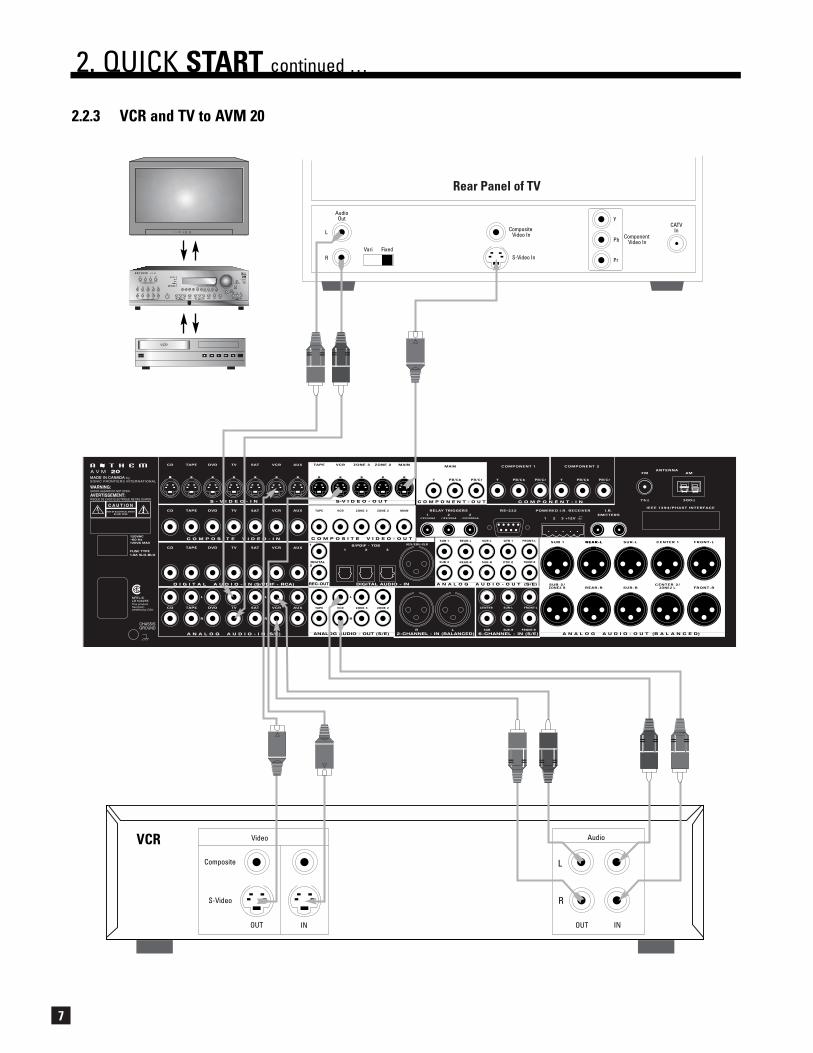
• VCR to AVM 20 – see diagram in section 2.2.3Video: Connect the VCR’s composite video output to Composite Video-In/VCR on the AVM 20.
To Record: Connect Composite Video-Out/VCR to the VCR’s composite video input.
Audio: Connect the L/R audio output of the VCR to Analog Audio-In/VCR on the AVM 20.To Record: Connect Analog Audio-Out/VCR to the L/R audio input of the VCR.
• AVM 20 to Amplifier(s) – see diagrams in sections 2.2.4 and 2.2.5From the AVM 20, connect Front-L, Front-R, Ctr1, Sur-L, Sur-R, Rear-L, and Rear-R AnalogAudio-Out to the Front-L, Front-R, Center, Sur-L, Sur-R, Rear-L, and Rear-R inputs of thepower amplifier(s). Follow the amplifier’s operating manual for connecting the speakers.
• AVM 20 to Powered Subwoofer – see diagrams in sections 2.2.4 and 2.2.5Connect Analog Audio-Out/Sub1 to the subwoofer’s line/low level input.
Reconnect the power to all components and turn them on. To turn on the AVM 20, move the switch on therear panel to the ‘on’ position and then press the POWER – MAIN button on the front panel.
3

4
To Watch a DVD:
• Press DVD Source on the front panel of the AVM 20.
• Select the TV input that corresponds to the one that the AVM 20’s Composite Video-Out/MAIN isplugged into.
• Place a DVD into the DVD player and press play. You should see the picture on your TV and hearsound from your speakers. Adjust volume using the Master Control Knob on the AVM 20.
To Watch a Video Tape:
• Press VCR Source on the front panel of the AVM 20.
• With your TV’s remote control, select the input that the AVM 20’s Composite Video-Out/MAIN isplugged into.
• Insert a tape into the VCR and press play. You should see the picture on your TV and hear soundfrom your speakers. Use the AVM 20 Master Control Knob on the front panel to adjust volume.
To Listen to a CD:
• Press CD Source on the front panel of the AVM 20.
• Place a CD into the CD player and press play. You should hear music coming from your speakers.Use the AVM 20 Master Control Knob on the front panel to adjust volume.
Note about Digital and Analog Inputs:
• You can change any input to Digital or Analog. Digital inputs use the AVM 20’s high-end digital toanalog converters and can be changed from RCA to Toslink or XLR connection. Analog inputs canbe set to Digital Signal Processing for bass management, bass/treble control, time alignment, andsurround modes, or Direct to bypass all digital stages. Auto-Dig uses the digital connection if adigital signal is sensed, and automatically switches to analog connection if there is no digitalsignal. For more information see sections 4.2.1 and 7.4.5.
Note about Your Speakers:
• The AVM 20 allows you to enter information about how many speakers you have in your system,as well as their relative size, type, and distance from your listening position. This speaker setupinformation is important in directing audio signals optimally, ensuring you get the best qualitysound from your system – see sections 7.4.2, 7.4.3, and 7.4.4.
2.2 CONNECTOR DIAGRAMS AND DESCRIPTIONS
The following pages of illustrations contain a variety of standard cable/connectors that are used to connectcomponents to your AVM 20. The various types, and what they are used for, are shown here:
2. QUICK START continued …
Analog LeftChannel
RCA Black orWhite RCA Red RCA Yellow
5-PinMini DIN Toslink
XLR Female(connects to output)
XLR Male(connects to input)1/4” Stereo
Analog RightChannel
Digital S/PDIF orComposite Video
S-Video Digital AudioS/PDIF
Analog Balanced or Digital AES/EBU
Analog Balanced orDigital AES/EBUHeadphone
3.5mmMini (Mono)
Relay TriggerIR Emitter
RCA Green:Component Y
RCA Blue:Component Pb/Cb
RCA Red:Component Pr/Cr

5
2. QUICK START continued …
CD Player Audio Out
R L
2.2.1 CD Player to AVM 20
CD Player
EJECT
Track 1

6
2.2.2 DVD Player and TV to AVM 20
2. QUICK START continued …
DVD Player
Composite Video Out S-Video OutAudio Out
R L
Digital Out
RCA Toslink
ComponentVideo Out
Pb
Y
Pr
DVD
AudioOut
Composite Video In Component
Video In
S-Video InVari Fixed
L
R
Pb
Pr
Y
Rear Panel of TV
CATVIn
Note: For info on ComponentVideo use, see sections4.3, 7.4.5, and 7.4.10
7
2.2.3 VCR and TV to AVM 20
2. QUICK START continued …
VCR Audio
R
L
OUT INOUT
S-Video
Composite
IN
Video
VCR
EJECT
AudioOut
Composite Video In Component
Video In
S-Video InVari Fixed
L
R
Pb
Pr
Y
Rear Panel of TV
CATVIn

8
Powered Subwoofer
LevelRCA
InputXLR
PO
WER
2.2.4 AVM 20 to Amplifier and Powered Subwoofer (RCA)
2. QUICK START continued …
REAR
LEFTINPUTS
FRONT
LEFT REAROUTPUT+ -
LEFT SURROUNDOUTPUT+ -
RIGHT REAROUTPUT+ -
LEFT FRONTOUTPUT+ -
RIGHT SURROUNDOUTPUT+ -
SURROUNDINPUTS
RIGHT
LEFT
CENTEROUTPUT+ -
RIGHT FRONTOUTPUT+ -
RIGHTINPUTS
REAR
FRONT
CENTERINPUT
NRTL/CLR 103255This product has been certified by CSA.
CHASSISGROUND
~
AUTO
MANUAL
TRIGGER
ON MODES
INPUT
5-24V AC/DC
OUTPUT
TR IGGERS MADE IN CANADA
THIS PRODUCT IS BUILT WITH THE FOLLOWING PATENTS:CDN. 2142644, U.S. 5636288
P V A 7
WARNING:SHOCK HAZARD DO NOT OPEN.
AVERTISSEMENT:RISQUE DE CHOC LECTRIQUE NE PAS OUVRIR.

9
2. QUICK START continued …
2.2.5 AVM 20 to Amplifiers and Powered Subwoofer (XLR)
To poweredsubwoofer
Trigger Setup Suggestion: If it is not necessary to have bothamplifiers turned on when stereosources are playing, set triggersto turn on only the 2-channelamplifier when a stereo source isselected (see section 7.4.9).

10
2
3
47
8
1
56
LAST
SLEEP
INPUT
FRT
CTR
THX
TIMERS
STATUS
PIPSWAP
MOVE
AVM SOURCE
COPY
AUXTAPE
DVDTV
SATVCR
CD
DVDTV
SATVCR
BASS
TREBLEBALANCE
2-Ch
CD
REC
MAINZ2
Z3AVM
PATH
DYNAMICS
VOLUME
CH PRE-SET
FM/AM PRE-SETS
SEEK
TUNE
SOURCE SEEK
LEARN
ENTER
MUTE
78
0
9
SELECT
SUBLFE
FMAM
SURRR
AVM OFF
DISPLAY TONE BYPASS
MODE
ON SCREEN
OFNI
EDIUG
BACK
SETUP
12
3
45
6
POWER
6-Ch
AVMPATH
110˚ from center
LAST
SLEEP
INPUT
FRT
CTR
THX
TIMERS
STATUS
PIPSWAP
MOVE
AVM SOURCE
COPY
AUXTAPE
DVDTV
SATVCR
CD
DVDTV
SATVCR
BASS
TREBLEBALANCE
2-Ch
CD
REC
MAINZ2
Z3AVM
PATH
DYNAMICS
VOLUME
CH PRE-SET
FM/AM PRE-SETS
SEEK
TUNE
SOURCE SEEK
LEARN
ENTER
MUTE
78
0
9
SELECT
SUBLFE
FMAM
SURRR
AVM OFF
DISPLAY TONE BYPASS
MODE
ON SCREEN
OFNI
EDIUG
BACK
SETUP
12
3
45
6
POWER
6-Ch
AVMPATH
*Dipole shown with ‘null’ facing listening area. Direct radiating – see diagram below.For accurate soundstage reproduction, speaker size and distance to the listener should be entered in theSetup Menu (see sections 7.4.2, 7.4.3, and 7.4.4).
1. Front-Left2. Center
3. Front-Right4. Surround-Right*
5. Rear-Right*6. Rear-Left*
7. Surround-Left*8. Subwoofer
2.3 SPEAKER PLACEMENT
These illustrations show the typical speaker placement for a 7.1-channel surround system, the ‘.1’ channelbeing the LFE (Low Frequency Effect). The Front and Center speakers are directed towards the listener fromthe front, while the Surround speakers are positioned to the sides, and the Rear speakers are positionedbehind the listener. Ideally, the Surround and Rear speakers should be positioned 2-3 feet above ear level.
2. QUICK START continued …
Surround Speaker Placement – Dipole Surround Speaker Placement – Direct Radiating
slightly behind listening position

11
3.1 FRONT PANEL LAYOUT
The front panel of the AVM 20 has the Master Control Knob, selection/navigation buttons, a display, status indicator LEDs, andthe Headphone jack .
See section 5 for complete information on Front Panel operation.
1 – Path selection
2 – Mode / Surround Decoder indicators
3 – Display
4 – FM • AM Preset selection
5 – FM • AM Tuning / Setup Navigation
6 – Master Control Knob
• Volume
• Tune for FM • AM
• Setting Adjustment for Mode; DD Dynamics; THX Options; Surround Mode Level / Bass / Treble / Balance; Path Bass / Treble / Balance; Display Brightness
• Setup Adjustment for Letters, Numbers, and Times
7 – Surround Mode / Headphone settings for Level / Bass / Treble / Balance
8 – Subwoofer / LFE Level settings
9 – Power On / Stand-By (MAIN / ZONE2 / ZONE3)
10 – Mute
11 – Status review / Setup (press and hold for 3 seconds)
12 – Balance setting
13 – Bass / Treble settings
14 – LED / Display Brightness setting (see section 7.4.10)
15 – Front Panel Remote Control IR Sensor
16 – Surround Mode / Dynamics / THX Options settings
17 – Headphone Jack
18 – Source selection
3. PANELS / DISPLAY/ REMOTE LAYOUT
LOGICLOGIC
1718 16 15 14 13 12 11 10 9
8
7
5 64321

12
3.2 FRONT PANEL DISPLAY
MAIN Display Example:
1 – Source selection (see section 5.4).
2 – Audio Input Format (see section 7.4.5) or Sleep Indicator if engaged (see section 6.5).
3 – Path that the information on the display refers to (see section 5.2).
4 – Volume setting. When MAIN, ZONE2, or ZONE3 are muted, “Muted” flashes instead of the currentvolume setting (see section 5.5).
5 – Surround Mode (if the Source is FM • AM, then the tuned station appears).
FM • AM Display Example:
1 – Source+Band. The tuner has three FM bands (FM1, FM2, and FM3) and one AM band. The numberafter the selected band is the preset station (see section 5.4.2).
2 – FM mode. Displays “St” when in stereo, “HB” when Hi-Blend is selected, or “Mn” when in mono ormono is selected (see section 5.4.2).
3 – Seek when tuning FM • AM stations (see section 5.4.2).
4 – Path (see section 5.2).
5 – Volume setting. When MAIN, ZONE2, or ZONE3 are muted, “Muted” flashes instead of the currentvolume setting (see section 5.5).
6 – Currently tuned FM • AM frequency to the nearest 0.1 MHz for FM and to nearest 10 kHz for AM(see section 5.4.2).
If changes take place simultaneously in different Paths, the hierarchy of the display info is:
1) Volume changes, 2) Front Panel activity, 3) MAIN, 4) ZONE2, 5) ZONE3, 6) RECORD, 7) HEADPHONE.
3. PANELS / DISPLAY/ REMOTE LAYOUT continued …
5 4
321
6 5
41 32

13
1 – 7 Composite Video RCA Inputs
2 – 7 S-Video Inputs
3 – 5 Composite Video RCA Outputs
4 – 5 S-Video Outputs
5 – Component Video Outputs (3 Jacks/ea)
6 – 3 Relay Trigger 3.5mm Outputs (Assignable)
7 – 2 Assignable Component Video Inputs (3 Jacks/ea)
8 – FM and AM Antenna Inputs
9 – IEEE 1394/PHAST Interface provision*
10 – 2 I.R. Emitters
11 – MAIN Analog Audio Balanced XLR Output (10 Jacks)
12 – 3 12V powered Infra Red (IR) 3.5mm Inputs
13 – RS-232 Interface Port (Bi-Directional)
14 – MAIN Analog Audio RCA Output (10 Jacks)
15 – Analog Audio 6-Channel RCA Input (6 Jacks)
16 – Digital Audio AES / EBU Input (Assignable)
17 – Analog Audio 2-Channel XLR Input (2 Jacks)
18 – ZONE2, ZONE3, and REC Analog Audio RCA Outputs
19 – 3 Digital Audio Toslink Inputs (Assignable)
20 – 2 Digital Audio RCA REC Outputs
21 – 7 Analog Audio RCA Inputs (L/R Jacks)
22 – 7 Digital Audio RCA Inputs
23 – Ground Terminal
24 – Power Cord Connection
3.3 REAR PANEL LAYOUT
The rear panel of the AVM 20 contains all connections, such as power connection, audio and video inputs and outputs, antennaconnections, and the RS-232 port which allows software upgrades and external control of the AVM 20.
* Interface card requires installation by a qualified dealer.
See section 4 for complete information on Rear Panel connections.
3. PANELS / DISPLAY/ REMOTE LAYOUT continued …
222324 21 19 1820 131415 121617
76 8
9
10
2 4 51 3
11

14
3.4 REMOTE CONTROL LAYOUT
1 – IR Transmitter (front face)2 – Transmission Indicator LED (red)3 – Power ON when in MAIN, ZONE2, or ZONE3 personality
Power ON/OFF for other components (see #4)Note: This does not turn the AVM 20 off (see #31)
4 – Path / Component ‘Personality’ selection5 – FM • AM Preset selection (6)6 – Selects Tone Bypass7 – Mode setting8 – Dynamics setting9 – FM • AM Preset Station Up10 – FM • AM Preset Station Down11 – THX Options settings12 – Center Channel setting for Level / Bass / Treble13 – Back (for Setup)14 – Subwoofer / LFE Level settings15 – Setup (Press & Hold for 3 seconds)16 – Source Seek17 – Balance setting18 – RECORD Path selection (Must be in MAIN – see #4)19 – Source selection (10 inputs)20 – Copy MAIN when ZONE2, ZONE3, or RECORD is selected21 – Bass setting22 – Treble setting23 – Surrounds / Rears setting for Level / Bass / Treble /
Balance24 – • Tune for FM • AM
• Setting Adjustment for Mode; DD Dynamics; THX Options; Surround Mode Level / Bass / Treble; PathBass / Treble; Timers; Display Brightness
• Navigation for Setup25 – • Seek for FM • AM
• Setting Adjustment for Surround Mode Balance;Path Balance
• Navigation for Setup (North / South / East / West)26 – Status / FM • AM Direct Entry / Setup selection27 – Fronts / Headphones setting for Level / Bass / Treble / Balance28 – Volume Down29 – Sleep Timer selection / Timers setting30 – Volume Up31 – Power OFF when in MAIN, ZONE2, or ZONE3 personality32 – Mute33 – Front Panel LED / Display Brightness setting / Audio Group Delay34 – On-Screen Display35 – Learn (for customization of remote)
See section 6 for complete information on operation of the Remote Control.
3. PANELS / DISPLAY/ REMOTE LAYOUT continued …
SLEEP
INPUT
FRT CTR
THX
TIMERS
STATUS
PIP SWAP MOVE
SSP SOURCE
COPY
AUX TAPE
DVD TV SAT VCR
CD
DVD TV SAT VCR
BASS TREBLE BALANCE
2-Ch
CD
REC
MAIN Z2 Z3
SSP PATH
DYNAMICS
VOLUME CH PRE-SET
FM/AM PRE-SETS
TUNESEEK
SOURCE SEEK
LEARN
ENTERMUTE
7 8
0
9
SELECT
SUBLFE
FMAM
SURRR
SSP OFF
DISPLAY
TONE BYPASS
MODE
ON SCREEN
INFO
GUIDE BACK
SETUP
1 2 3
4 5 6
POWER
6-ChSSP PATH
SSP OFFLAST
2
1
3
4
6
7
8
11
16
17
1819
35
20
34
26
31
23
21
27
28
33
29
22
12
13
14
15
9
5
10
25
24
30
32
4.1 CONNECTING POWER TO THE AVM 20
Connect the power cord to the back of the AVM 20 and then to a 105 to 130 Volt, 60 Hz AC outlet.
4.2 AUDIO CONNECTIONS
There are two methods of transmitting audio signals: Analog and Digital. Analog is an electrical waveformrepresentation of sound and requires one cable for each channel. Digital represents sound using a sequenceof numbers and requires only one cable for all channels.
Every audio input in the AVM 20 can be changed from the factory setting to either Digital or Analog, except2-Ch BAL and 6-Ch S/E, which accept analog signals only (see section 7.4.5).
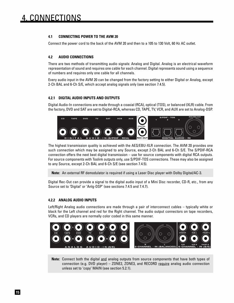
4.2.1 DIGITAL AUDIO INPUTS AND OUTPUTS
Digital Audio-In connections are made through a coaxial (RCA), optical (TOS), or balanced (XLR) cable. Fromthe factory, DVD and SAT are set to Digital-RCA, whereas CD, TAPE, TV, VCR, and AUX are set to Analog-DSP.
The highest transmission quality is achieved with the AES/EBU-XLR connection. The AVM 20 provides onesuch connection which may be assigned to any Source, except 2-Ch BAL and 6-Ch S/E. The S/PDIF-RCAconnection offers the next best digital transmission – use for source components with digital RCA outputs.For source components with Toslink outputs only, use S/PDIF-TOS connections. These may also be assignedto any Source, except 2-Ch BAL and 6-Ch S/E (see section 7.4.5).
Note: An external RF demodulator is required if using a Laser Disc player with Dolby Digital/AC-3.
Digital Rec-Out can provide a signal to the digital audio input of a Mini Disc recorder, CD-R, etc., from anySource set to ‘Digital’ or ‘Anlg-DSP’ (see sections 7.4.5 and 7.4.7).
4.2.2 ANALOG AUDIO INPUTS
Left/Right Analog audio connections are made through a pair of interconnect cables – typically white orblack for the Left channel and red for the Right channel. The audio output connectors on tape recorders,VCRs, and CD players are normally color coded in this same manner.
Note: Connect both the digital and analog outputs from source components that have both types ofconnection (e.g. DVD player) – ZONE2, ZONE3, and RECORD require analog audio connectionunless set to ‘copy’ MAIN (see section 5.2.1).
15
4. CONNECTIONS

16
Caution for DTS: With DTS-CDs or DTS Laser Discs, do not use analog connection if your player doesnot have the DTS logo on its faceplate, otherwise a loud noise will be produced at the analog outputs ofthe player. Players that have the DTS logo can pass a DTS-encoded signal through their digital outputs,but may still require a setup change to enable it (see player’s operating manual).
4.2.3 2-Ch BALANCED AND 6-Ch SINGLE-ENDED (S/E) ANALOG AUDIO INPUTS
The 6-Ch S/E input is intended primarily for DVD-Audio and multichannel SACD players. If unused for thispurpose, the Front-Left and Front-Right connections can be used as a 2-channel input.
Note: When 6-Ch S/E is selected as the Source, the video signal from the DVD input will be routed tothe video outputs – connect your player’s video output to the DVD input (sections 4.3 and 7.4.5).
The 2-Ch BAL and 6-Ch S/E inputs can be set to either bypass all digital stages in the AVM 20 or to includedigital stages, so that bass management, time alignment, surround modes, bass/treble control, audio groupdelay, and THX post-processing can be enabled (see sections 5.7, 5.8, 7.4.2, and 7.4.5).
4.2.4 ANALOG AUDIO OUTPUTS
Balanced XLR connection offers the highest transmission quality, particularly over long cable lengths,because it rejects noise and hum pickup. On the AVM 20, XLR output voltage is twice that of RCA outputvoltage (or 6 dB higher). If your amplifier does not have balanced inputs, use Single-Ended RCA connection.
The AVM 20 also provides parallel outputs for a second Center channel and/or Subwoofer. If the BalancedSUB2 and CENTER2 outputs are not being used for this purpose, they can be re-configured to act asBalanced outputs for ZONE2 to ensure lower noise with longer cable runs (see sections 5.2 and 7.4.7).
If you’re using a 6.1-channel speaker system, with one Rear speaker, Rear-L or Rear-R can be used as theoutput connection (see section 7.4.2).
The Analog Audio RECORD outputs for your tape recorder and VCR are shown below, together with theoutputs for ZONE2 and ZONE3 amplifiers:
4. CONNECTIONS continued …
17
4. CONNECTIONS continued …
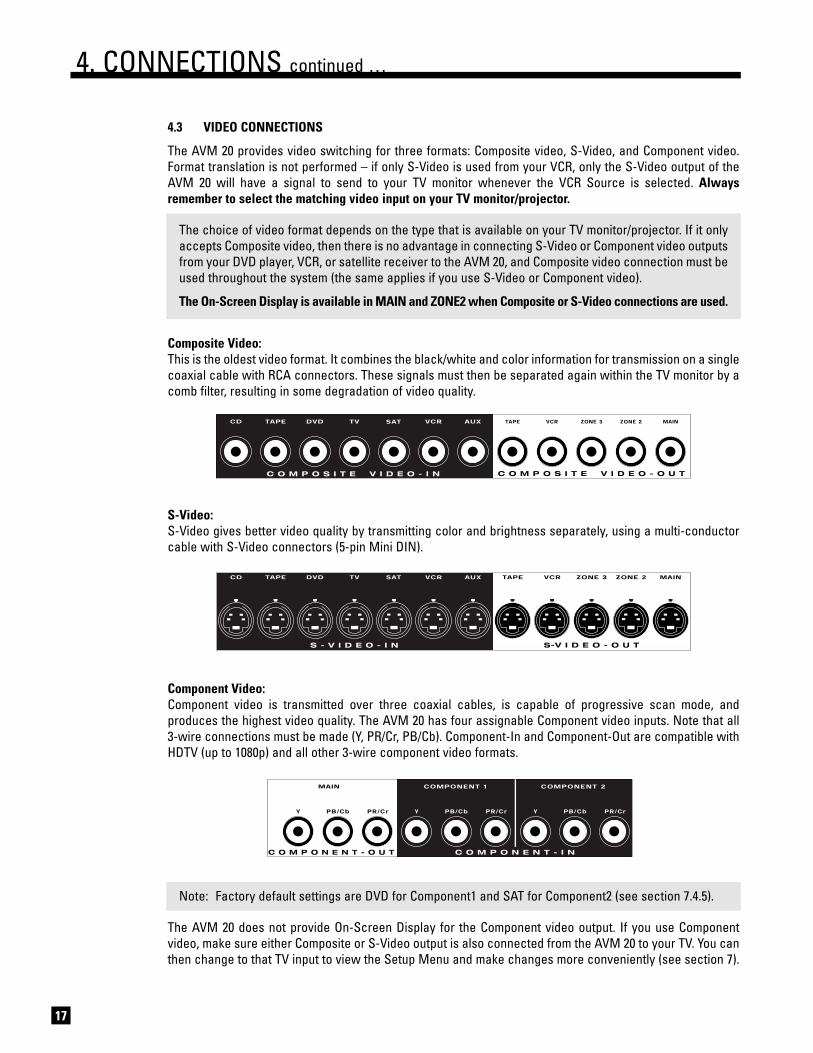
4.3 VIDEO CONNECTIONS
The AVM 20 provides video switching for three formats: Composite video, S-Video, and Component video.Format translation is not performed – if only S-Video is used from your VCR, only the S-Video output of theAVM 20 will have a signal to send to your TV monitor whenever the VCR Source is selected. Alwaysremember to select the matching video input on your TV monitor/projector.
The choice of video format depends on the type that is available on your TV monitor/projector. If it onlyaccepts Composite video, then there is no advantage in connecting S-Video or Component video outputsfrom your DVD player, VCR, or satellite receiver to the AVM 20, and Composite video connection must beused throughout the system (the same applies if you use S-Video or Component video).
The On-Screen Display is available in MAIN and ZONE2 when Composite or S-Video connections are used.
Composite Video:This is the oldest video format. It combines the black/white and color information for transmission on a singlecoaxial cable with RCA connectors. These signals must then be separated again within the TV monitor by acomb filter, resulting in some degradation of video quality.
S-Video:S-Video gives better video quality by transmitting color and brightness separately, using a multi-conductorcable with S-Video connectors (5-pin Mini DIN).
Component Video:Component video is transmitted over three coaxial cables, is capable of progressive scan mode, andproduces the highest video quality. The AVM 20 has four assignable Component video inputs. Note that all 3-wire connections must be made (Y, PR/Cr, PB/Cb). Component-In and Component-Out are compatible withHDTV (up to 1080p) and all other 3-wire component video formats.
Note: Factory default settings are DVD for Component1 and SAT for Component2 (see section 7.4.5).
The AVM 20 does not provide On-Screen Display for the Component video output. If you use Componentvideo, make sure either Composite or S-Video output is also connected from the AVM 20 to your TV. You canthen change to that TV input to view the Setup Menu and make changes more conveniently (see section 7).

18
4. CONNECTIONS continued …
DVD Player, Satellite Receiver, and TV Connections with AVM 20 as Video Input Selector
AudioOut
Composite Video In Component
Video In
S-Video InVari Fixed
L
R
Pb
Pr
Y
Rear Panel of TV
CATVIn
DVD Player
Composite Video Out S-Video OutAudio Out
R L
Digital Out
RCA Toslink
ComponentVideo Out
Pb
Y
Pr
Satellite Receiver
Composite Video Out S-Video OutAudio Out
R L
Digital Out
RCA Toslink
ComponentVideo Out
Pb
Y
Pr
DVD
SATELLITE
Note: For info on ComponentVideo use, see sections4.3, 7.4.5, and 7.4.10

4. CONNECTIONS continued …
19
4.4 POWERED I.R. (INFRA RED) RECEIVERS
External IR repeaters allow the Remote Control to be used from other locations inyour home. Once a repeater is wired to a selected room, connect it to one of thethree I.R. RECEIVER inputs through the removable terminal block. To use theterminal block, remove it from the AVM 20, loosen the proper screw, insert thewire in the slot, tighten the screw onto the wire, and insert the terminal block intothe AVM 20. See section 7.4.9 for Setup information.
In addition, there is no need for an external 12V supply to power the repeaters –use the AVM 20’s built-in supply instead for up to three repeaters, and connectaccording to the repeater manufacturer’s instructions.
Note: For installers – The AVM 20’s IR inputs sense modulated 38 kHz carrier, not demodulated data.With some control systems, an emitter face-to-face with an IR repeater may be needed.
4.5 I.R. (INFRA RED) EMITTERS
External IR emitters, also known as flashers, allow control of your sourcecomponents from any location in your home that has an IR repeater wired to theback of the AVM 20. Position a flasher in front of the source components andconnect to one of the two I.R. EMITTER outputs – IR commands coming in throughthe rear I.R. RECEIVER inputs are re-transmitted through the flashers.
4.6 RELAY TRIGGERS
If your other components have provisions for a trigger, you can automatically turnthem on and off together with the AVM 20, or when a specified Source is selected.Connect a trigger output from the AVM 20 to the trigger input of your poweramplifier, TV monitor, etc., using a cable with 3.5mm mono mini plugs.
Trigger3 is designed to provide the extra current (up to 200 mA) required by relays in larger projectors andmotorized screens. Depending on the equipment, a thicker wire gauge may be required (consult your dealer).
The AVM 20 provides flexible trigger options. From the factory, all the triggers are disabled. Through theSetup Menu, the conditions for enabling triggers can be specified (see section 7.4.9).
4.7 FM • AM ANTENNAS
To connect the FM antenna, first connect the two antenna wires to thescrew terminals of the 75-ohm to 300-ohm adapter. Then connect theadapter to the FM ANTENNA connector on the AVM 20. If your local cablecompany provides FM service, connect the cable directly to the AVM 20instead of using the adapter.
To connect the AM loop antenna, press the spring-loaded tabs of the AMANTENNA connector, insert the bare ends of the wire from the loop antennaand release the tabs.
Once both antennas are connected, move each of them around until bestreception is found. For the FM antenna, this will usually be in a “T” formation.
75-ohm to 300-ohm adapter

20
The AVM 20 is best understood as a piece of equipment that contains three control components in onechassis. Path best describes how this tremendous flexibility of the AVM 20 is arranged:
• It is first of all a state-of-the-art Music and Home Theater Preamplifier • Processor • Tuner (MAIN Path) with independent Source selection for recording (RECORD Path).
• It is also a high-end Whole House Entertainment Control Center that allows you to direct and adjustthe output of a variety of source components to other rooms in your home (ZONE2 and ZONE3 Paths).
5.1 POWER ON/OFFWhen turned on, the AVM 20 comes on at the pre-programmed volume setting (see section 7.4.8).
• MAIN On: There are various of ways of switching MAIN on: • Press MAIN in the POWER group (fig. right).• Press MAIN in the PATH group (fig. below). • If ZONE2 and ZONE3 are off, press any SOURCE, FM • AM preset
(1 through 6), or TUNE to immediately power-up MAIN.• MAIN Off: Press MAIN in the POWER group.• ZONE2 or ZONE3 On: Press ZONE2 or ZONE3 in the POWER group or in the PATH group. • ZONE2 or ZONE3 Off: Press ZONE2 or ZONE3 in the POWER group.• RECORD On: Press RECORD in PATH group. MAIN will turn on simultaneously. The Front Panel
Display will show MAIN Path information (see highlighted notation in section 5.2).• RECORD Off: Press MAIN in the POWER group. This turns off MAIN and RECORD simultaneously.
5.2 PATH SELECTION
Path routes Sources to the MAIN, ZONE2, ZONE3, or RECORD outputs.
• MAIN: As the name suggests, MAIN routes the audio/videosources to your main listening/viewing room, with outputs foryour MAIN TV monitor and 7.1-channel audio.
• ZONE2 and ZONE3: Routes any audio/video source to other listening/viewing rooms in your home.The chosen Source can be either the same or different from the Source selected in other paths.ZONE2 and ZONE3 each have outputs for a TV monitor and 2-channel audio. To listen to a Sourcethat does not have Analog Audio-In connection, you must ‘copy’ it from MAIN (see section 5.2.1).
• RECORD: Allows you to record audio/video sources independently of what is selected in otherpaths. Composite and S-Video, and fixed-level analog audio outputs are available for your taperecorder and VCR. In addition, there are two configurable coaxial digital outputs: DIGITAL1 can beset to output the audio of any digital Source, or convert an analog Source to digital (must be set toAnlg-DSP in the Setup). DIGITAL2 can be set to output the same signal as DIGITAL1, or any of theSources set to Digital. See sections 7.4.5 and 7.4.7 for an explanation on how to set input and outputformats. As with ZONE2 and ZONE3, RECORD only operates with an analog input or by ‘copying’MAIN (see section 5.2.1).
The AVM 20 automatically returns to MAIN a few seconds after an adjustment is made in ZONE2, ZONE3,RECORD, or HEADPHONE*. This is designed to prevent accidents. Say, for example, someone enters theMAIN room and turns up the volume – if the AVM 20 stayed in ZONE2, then the volume would increase inZONE2, not MAIN. Since the person adjusting the volume doesn’t hear any change, chances are he or shewould just keep turning it up and wonder what’s wrong, until something potentially ‘bad’ happens in ZONE2.If you’ve seen “The Party” and remember the hilarious scene where Peter Sellers messes with the console,you probably understand. The timeout setting can be changed in the Setup (see section 7.4.10).
* Except when MAIN is off or HEADPHONE is set to ‘Mute’ the MAIN speakers (see section 7.4.8).
5. FRONT PANEL OPERATION
LOGIC
LOGIC

5.2.1 COPYING THE MAIN PATH TO ZONE2, ZONE3, OR RECORD
This unique copy feature allows the Source selected in MAIN (e.g. DVD, CD, etc.) to also be directed toZONE2, ZONE3, or RECORD from either analog or digital inputs.
The Source selected in MAIN can be copied to another Path as follows:
• ZONE2 or ZONE3: Press and hold MAIN, then press ZONE2 or ZONE3 (can also be done in reverse).
• RECORD: Press and hold MAIN, then press RECORD (can also be done in reverse).
When MAIN is copied, the display reads “–MAIN–> ZONE2”, “–MAIN–> ZONE3”, or “–MAIN–> REC” afterthe selected Source, along with the information normally displayed.
Down-Mixing to 2-Channel Stereo:The Center, Surround, and Rear channels can be mixed into the Left and Right Channels for the ZONE2,ZONE3, TAPE, and VCR outputs. This can be done by the DVD player or the AVM 20:
• AVM 20 Down-mix: If the digital audio output from your DVD player is connected to the AVM 20,the 2-channel down-mix from Dolby Digital or DTS will be done by the AVM 20 whenever you copyMAIN to ZONE2, ZONE3, or RECORD.
• DVD Player Down-mix: If the Left/Right analog outputs from your DVD player are connected to theAVM 20’s Analog Audio-In, the Dolby Digital down-mix done by your DVD player can be used forZONE2, ZONE3, TAPE, and VCR outputs, without having to copy MAIN. Note that DVD players do notnormally provide a down-mix for DTS material.
Note: Even when doing this, keep the digital output from your DVD player connected to the AVM 20, otherwise MAIN will not receive the digital signal needed for multi-channel output.
5.3 MASTER CONTROL KNOB
Besides being a Volume Control, the MASTER CONTROL KNOB also operates many other functions, includingadjustment of Surround Mode Level / Bass / Treble / Balance; Path Bass / Treble / Path Balance; FM • AMtuning; Mode (Music / Pro Logic); THX Options; DD Dynamics and Display Brightness selection.
From this point in the manual, the MASTER CONTROL KNOB (MCK) will be referred to extensively.
5.4 SOURCE SELECTION
The AVM 20 accommodates up to nine external sources plusthe built-in FM • AM Stereo Tuner.
The Sources on the front panel are: CD, 2-Ch BAL, 6-Ch S/E,TAPE, FM • AM, DVD, TV, SAT, VCR, and AUX.
You can also change the Source name as it appears on theFront Panel and On-Screen displays (see section 7.4.5).
5.4.1 6-CHANNEL S/E INPUT
For the most part, the 6-Channel S/E input is intended for multichannel DVD-Audio and SACD players. Ifunused for 6-channel audio, the Front-Left and Front-Right inputs can be used as a 2-channel input.
When the 6-Channel S/E input is selected, the video signal from the DVD input will be routed to theComposite, S-Video, and MAIN Component (if assigned to DVD) outputs to allow track selection andnavigation of the disc’s menu.
The 6-Ch S/E audio can be routed to ZONE2, ZONE3, and RECORD outputs as long as Copy mode is used, sothat a stereo down-mix can be created (see section 5.2.1).
5. FRONT PANEL OPERATION continued …
21
LOGIC

5.4.2 FM • AM TUNER
The AVM 20 has a built-in FM • AM tuner, which is common to all Paths. The station that is selected in eitherMAIN, ZONE2, ZONE3, or RECORD is automatically shared with all other Paths.
Manual Tuning:Select the desired band by pressing FM • AM, then press TUNE and rotate theMaster Control Knob.
Automatic Tuning:To automatically find the next station, press SEEK or SEEK. To scan and listen to all available radiostations for a few seconds, press and hold SEEK or SEEK for about a second. The ‘Sk ’ or ‘ Sk’indicator on the display will change to ‘Prv ’ or ‘ Nxt’. To stop scanning, press one of theSEEKbuttons to return to Seek mode, or press TUNE to tune manually. Press TUNE a second time torestore the regular functions and display (the TUNE function does not time out).
Presets:18 FM and 6 AM stations can be stored in the AVM 20. Thepresets are divided into four banks of six. By repeatedlypressing FM • AM, the display will show that you are cyclingthrough ‘FM1’, ‘FM2’, ‘FM3’, ‘AM’. Once you have selected thedesired bank, you can store the currently tuned radio station by pressing and holding one of the six presetkeys (1 through 6) for about a second. You can even do this while scanning for stations. The lower line of thedisplay briefly flashes once the station is stored. To recall a preset, select the bank that it is in, then pressthe respective preset key. To skip a preset, set it to 87.5 FM or 530 AM.
ST / HiB / M:If FM reception is weak, switching a station out of stereo can reduce or eliminateunwanted hiss and noise. Press ST / HiB / M repeatedly to cycle through Stereo, Hi-Blend,or Mono. Hi-Blend offers an alternative to Mono, offering decreased noise without thecomplete loss of stereo – it decreases hiss and noise by reducing some stereo separationonly at higher frequencies. The setting is memorized individually for each preset.
5.4.3 SIMULCAST
The AVM 20’s Simulcast feature allows you to select an alternate audio Source to combine with the currentlyselected video Source. For example, you could view a sports event on TV while listening to your favoriteFM/AM station. Simulcast is available for all Paths.
To change the audio Source without changing the currently selected video Source (e.g. TV), simply press andhold the desired video Source button for 2 seconds. The display will show the video Source (top line), audioSource and Path (bottom line), for the duration of the Function Timeout (see section 7.4.10) – press anotherSource button (e.g. FM/AM) during this period to change the audio Source.
Once the Function Time elapses, the regular display will return, but there will be a ‘+’ beside the displayedaudio Source to indicate Simulcast mode, and the Source Selection LED will still indicate the video Source.
To exit Simulcast mode, after the Function Timeout elapses, press and release any Source button (e.g. TV) –both the audio and video will switch to this selection.
22
5. FRONT PANEL OPERATION continued …LOGIC
LOGIC
LOGIC

23
5. FRONT PANEL OPERATION continued …
5.5 VOLUME CONTROL
The volume of each Path is controlled separately.
• MAIN: Adjust using the Master Control Knob. If yourspeaker levels have been calibrated to 75 dB SPL, theTHX Reference Level for movie playback is 0 dB, thelevel at which the film was originally presented in movietheaters (see Dialog Normalization and section 7.4.4).
• ZONE2 or ZONE3: Press ZONE2 or ZONE3, then adjust.
• HEADPHONE: Check that the display reads MAIN, pressFRONTS twice, then adjust. MAIN can be set to mutewhenever headphones are inserted (see section 7.4.8).
Dialog Normalization:Dolby Digital program material contains non-audio data which the AVM 20 uses to adjust playback level,when necessary, so that volume variations between movies and programs are eliminated. Without DialogNormalization, movies not encoded at standardized levels for the dialog could lose dynamic range – higherlevels can result in distorted peaks, lower levels can result in quiet sounds disappearing into the noise floor.Dialog Normalization also ensures that Dynamics control (section 5.8.10) works as intended.
If the display reads “Dial Norm Offset -4.0 dB” at the start of a movie, it is indicating that the encoded levelis higher than standard by 4.0 dB – the playback level of all channels is then automatically reduced by 4 dB.
Mute:When MUTE is pressed, the audio of the selected Path is silenced (or reduced – seesection 7.4.8). Press MUTE again, or rotate the Master Control Knob to adjust volume, andsound will return. MAIN, ZONE2, ZONE3, and Headphone are muted independently.
• MAIN: Press MUTE.
• ZONE2 or ZONE3: Press ZONE2 or ZONE3, then press MUTE.
• HEADPHONE: Check that the display reads MAIN, press FRONTS twice then press MUTE.
Always make sure you are in the Path that you want to adjust before changing Volume or pressing Mute.
5.6 SURROUND MODE LEVELS
The AVM 20 memorizes the level of one group of channels relative to another separately for each surroundmode (section 5.8), and for the 6-Ch S/E input. To make a change for the surround mode that is currently playingand showing on the display, adjust as follows:
• Fronts: Press FRONTS • , then adjust (this changes Left, Center, and Right levels together).
• Center: Press CENTER, then adjust.
• Surrounds: Press SURR • REARS, then adjust.
• Rears: Press SURR • REARS twice, then adjust.
• Subwoofer Only: Press SUB • LFE, then adjust. Pressing SUB • LFE twice allows you to reduce thelevel of the LFE (Low Frequency Effect) output from any source with a “.1” LFE channel i.e. DVD,Laser Disc, DTS-CD, or satellite, while leaving the bass derived from the other channels at theiroriginal levels. Some of these discs exhibit prodigious levels of bass, and may need LFE adjustment.
Note: When listening in Stereo (CD, FM • AM, etc.) with Front speakers set to ‘Large’, the Subwoofermust be set to ‘Super’ if you want it to play (see section 7.4.2).
LOGIC
MASTER CONTROL KNOB
LOGIC

5.7 BASS / TREBLE / BALANCE
MAIN, ZONE2, ZONE3, and HEADPHONE all have independentBass/Treble and Balance adjustments.
To change the Bass, Treble, or Balance of:
• MAIN – All Speakers Simultaneously: Press BASS, TREBLE, or BALANCE, then adjust.
• MAIN – Fronts Only: Press FRONTS • , press BASS, TREBLE, or BALANCE, then adjust.
• MAIN – Center Only: Press CENTER, press BASS or TREBLE, then adjust.
• MAIN – Surrounds Only: Press SURR • REARS, press BASS, TREBLE, or BALANCE, then adjust.
• MAIN – Rears Only: Press SURR • REARS twice, press BASS, TREBLE, or BALANCE, then adjust.
• ZONE2 or ZONE3: Press ZONE2 or ZONE3, press BASS, TREBLE, or BALANCE, then adjust.
• HEADPHONE: Press FRONTS • twice, press BASS, TREBLE, or BALANCE, then adjust.
Note: Bass/Treble is not available for sources set to Anlg-Dir (see section 7.4.5).
Tone Bypass:Pressing TONE BYPASS disables Bass/Treble in the selected Path. To enable Bass/Treble again, be certainyou are in the Path that you want to adjust and press either BASS or TREBLE.
5.8 SURROUND MODES
A surround mode is signal processing that enhances original source material.There are two types of surround modes – those that apply to stereo sourcematerial and those that pertain to 5.1-channel source material.
Stereo Source Material:This includes both analog stereo and digital stereo (stereo PCM or Dolby Digital-2.0) source material. Varioussurround modes can be applied, some of which can provide up to 7.1 channels of output. These aredescribed in detail in section 5.8.1. Each Source also keeps its own Mode setting, so you can, for example,set VCR to ‘AnthemLogic-Cinema’, and then set CD to ‘AnthemLogic-Music’ – when you switch to eachSource, their respective Mode will be remembered.
Note: Surround modes are not available for inputs set to Anlg-Dir (see section 7.4.5).
Regarding analog VCR input: With analog, there is no way for any processor to detect Dolby Surroundencoded material. Dolby Pro Logic must therefore be turned on manually by selecting it in the Mode options.All other stereo source surround modes are also available.
5.1-Channel Source Material:The AVM 20 detects the digital format that you select in the DVD menu and automatically engages eitherDolby Digital-5.1 or DTS-5.1 – whichever applies – to provide 5.1 discrete channels. Each format also has anadditional Mode that can be applied – Dolby Digital EX (for Dolby D-5.1) and DTS Neo:6 (for DTS-5.1).
To make operation easier, these additional modes can only be turned on/off after the movie has started andthe AVM 20 has detected the format. As soon as the display reads either Dolby D-5.1 or DTS-5.1, you can setthe additional surround mode On or Off – there is usually plenty of time to do so when the film studio’s logosare played at the beginning of the movie. The last setting for these additional surround modes is rememberedso you do not have to change them from movie to movie (see sections 5.8.4 and 5.8.5).
Note: Surround modes for stereo source material are not available for 5.1-channel source material.
24
5. FRONT PANEL OPERATION continued …
LOGIC
LOGIC

THX Options:Provided that you are using two Rear speakers (in addition to Surrounds), all THX modes are available forDolby Digital 5.1 and DTS 5.1 source material. THX Cinema is the only THX mode available for Stereo, ProLogic, Pro Logic II-Movie and Neo:6-Cinema source material (THX is covered in detail in section 5.8.6).
Note: Certain surround modes and THX modes offer 6.1 or 7.1 channels of output. These extra channelsare for one or two Rear speakers. If you are using a 5.1 system and have Rears set to ‘None’(Speaker Configuration menu – section 7.4.2), rear channel information will not be lost, but willremain in the L/R Surround speakers.
5.8.1 AnthemLogic™
These are proprietary surround modes developed by Anthem that offer outstanding surround performanceand can be applied to any 2-channel source material:
AnthemLogic-Music™
AnthemLogic-Music™ enhances the stereo listening experience without detracting from thestereo soundstage. Through extensive listening tests a very effective design was developed.This is a minimalist design that uses no echo or reverberation effects that could negativelyaffect the purity of the sound.
AnthemLogic-Music™ provides up to 6.1 channels of output, depending on your speaker configuration – L/RFronts, L/R Surrounds, L/R Rears and Subwoofer. AnthemLogic-Music™ does not utilize the Center Channel,to ensure that the purity of the stereo music soundstage will in no way be compromised.
AnthemLogic-Music™ is very effective in creating an expansive musical soundstage that psychoacousticallyhelps to remove the barrier of the listening room itself, and it does so in a completely non-intrusive, naturaland very compelling way. This is the factory default 2-channel Mode for CD, 2-Ch BAL, TAPE, and FM • AM.
AnthemLogic-Cinema™
AnthemLogic-Cinema™ provides a large, enveloping and dynamic movie listening experiencethat makes 2-channel movies sound more like what is experienced in a state-of-the art movietheater. Again through extensive listening tests a very effective design was developed. Thisis also a minimalist design that avoids the use of echo effects, which could otherwisenegatively affect the purity of the sound.
Whereas other movie surround modes offer 5.1 channels of output, AnthemLogic-Cinema™ uses the rearspeakers to provide up to 7.1 channels of output, depending on your speaker configuration.
AnthemLogic-Cinema™ provides the missing link that lets you experience 7.1 channels of output for fullimpact home theater sound, from any 2-channel stereo analog source such as VCR or TV, or any Dolby Digital2-channel source, such as DVD or satellite. This is the factory default Mode for DVD, TV, SAT, VCR, and AUX.
5.8.2 DOLBY DIGITAL-2.0
Many Dolby Digital-2.0 soundtracks contain a flag that can be used to automatically activate the Pro Logic II-Movie mode. The AVM 20 can be set to use this flag, or it can be set to override this flag.
With Dolby Digital-2.0 material playing, press MODE and use the Master Control Knob to select one of thefollowing:
• PLII-Movie: Auto – engages Pro Logic II-Movie whenever the Dolby Surround flag is present. Whenthere is no flag, the selected 2-channel Mode will apply (see section 5.8.3).
• PLII-Movie: Off – overrides the flag to allow selection of a different surround Mode (or Stereo) if youprefer. Once ‘Off’ is selected, press MODE a second time and set the surround mode of your choice.
25
5. FRONT PANEL OPERATION continued …
LOGIC
6.1CHANNELOUTPUT
7.1CHANNELOUTPUT

26
5. FRONT PANEL OPERATION continued …
5.8.3 SURROUND MODES FOR STEREO SOURCE MATERIAL
Press MODE and rotate the Master Control Knob to to cycle through the following surround modes:
Pro Logic II-Movie and THX must be Off for all Modes on this page to be available (see sec. 5.8.2 and 5.8.6).
Stereo: No surround mode is applied.
AnthemLogic-Music: 6.1 – One of Anthem’s proprietary surround modes specifically designed toexpand the stereo soundstage of stereo music in a very natural way without anyloss of soundstage integrity or image focus. The Center channel is not used.
AnthemLogic-Cinema: 7.1 – Another proprietary mode from Anthem, specifically designed to providethe impact of a large theater experience from 2-channel movies and TV programs.
Pro Logic II-Music: 5.1 – Can be used with stereo music material. The following three parameterscan be adjusted by pressing the MODE button one, two, or three times while inPro Logic II-Music, and rotating the Master Control Knob:
Center Width is adjustable from 0 to 7 – ‘0’ places all Center sound in the Centerspeaker, while ‘7’ places it equally in the Left and Right channels.
Dimension helps achieve the desired front-to-back balance by providing sevensteps of adjustment between the Surround and Center channels.
Panorama is effective for recordings with strong left or right channel elements.When ‘On’, it extends the front stereo image to include the Surround channels.
Pro Logic II-Movie: 5.1 – The next generation Dolby Surround decoder for 2-channel movies and TVprograms, with improved spatiality and directionality.
Dolby Pro Logic: 5.1 – Still available, in case there is a desire to hear program “as it used to be”.
DTS Neo:6-Music: 6.1 – Can be used with stereo music material to create 6.1 output channels. Thecenter image can be adjusted by pressing MODE while in Neo:6 Music, androtating the Master Control Knob:
Center Image is adjustable from 0 to 5 – increasing the number gives morecenter channel prominence.
DTS Neo:6-Cinema: 6.1 – A matrix decoder that can be used with all matrix-encoded movies.Separation is created by allowing various sounds to be placed at differentpoints in the sound field simultaneously.
All-Channel Stereo: 7.1 – The Left and Right channels are also sent to the Surround and Rearchannels, while the Center channel and Subwoofer receive a combination ofboth. Some processing is used to retain image clarity. Useful for playing musicat parties so that it can be heard with equal loudness in all parts of the room.
All-Channel Mono: 7.1 – Combines the Left and Right channels and sends the signal to all speakers.
Mono: Combines the Left and Right channels and sends the signal to the Center speaker.
Mono-Academy: Gives a presentation closer to the original on movies made from the 1930s to1960s, which relied on high-frequency rolloff for sound balance and to maskinherent hiss. Use only with old mono movies that sound overly bright and hissy.
Note: Channels of output are indicated in bold type – ‘.1’ refers to derived subwoofer channel (not LFE).

5. FRONT PANEL OPERATION continued …
5.8.4 DOLBY DIGITAL EX
Dolby Digital EX can be used to decode DVDs encoded in Dolby Digital Surround EX. Dolby Digital EX usesDolby Pro Logic II to extract the rear channel information from the two Surround channels. Dolby Digital EXcan also be applied to Dolby Digital 5.1 channel material that is not encoded in Dolby Digital Surround EX,however, the Rear channel information may or may not be pleasing depending on the soundtrack.
A list of movies encoded in Dolby Digital Surround EX can be found on the Dolby web site at www.dolby.comand THX web site at www.thx.com. Since most titles currently do not have a flag to engage Dolby Digital EXdecoding automatically, be sure to set Dolby Digital EX to ‘On’ when playing unflagged Surround EX titles –while the DVD is playing, press MODE and use the Master Control Knob to turn Dolby Digital EX ‘On’. Toautomatically decode DVDs that contain the Surround EX flag, set Dolby Digital EX to ‘Auto’.
Note: To use Dolby Digital EX without THX processing, THX must be ‘Off’ (see section 5.8.6).
5.8.5 DTS-ES
There are two ways that Rear channel information is encoded in DTS-ES – Matrix and Discrete:
• Matrix – DTS-ES Matrix movies contain a matrixed Rear channel. The AVM 20 automaticallyengages Neo:6 to decode DTS-ES Matrix. As well, Neo:6 can be turned on manually and applied toDTS 5.1-channel material – while the DVD is playing, press MODE and use the Master Control Knobto turn Neo:6 ‘On’. A mono Rear channel will be derived from the Left and Right Surround channels.This Rear channel may or may not be pleasing depending the soundtrack and your preferences.
• Discrete – DTS-ES Discrete movies contain an independent Rear channel. When one of thesemovies is playing, the AVM 20 automatically engages DTS-ES Discrete decoding.
5.8.6 THX ULTRA2 / THX SURROUND EX
Each THX mode includes a specific combination of the following:
• Re-Equalization – De-emphasizes high frequencies in the front channels, and in THX Surround EX,the rear channels as well. Soundtracks commonly have pre-emphasized treble because they aremixed for movie theaters where high frequencies are usually absorbed. They can then sound overlybright when played back in the home. Re-Equalization restores the correct tonal balance forwatching a movie soundtrack in a home theater environment. Some TV shows that are broadcastin Dolby Surround also benefit from Re-Equalization, whereas some movies on DVD may alreadyhave Re-EQ applied and do not require it from the processor. To defeat Re-EQ, press the THX buttona second time after selecting a THX mode to display “RE-EQ Filters: On (Off)”, then adjust.
• Timbre Matching – The human ear changes our perception of a sound depending on the directionfrom which the sound is coming. In a movie theatre, there is an array of surround speakers so thatthe surround information is all around you. In a home theatre, you use only two speakers located tothe side of your head. Timbre Matching, which includes Re-EQ, filters the information going to thesurround speakers so that they more closely match the tonal characteristics of the sound comingfrom the front speakers. This ensures seamless panning between the front and surround speakers.
• Adaptive Decorrelation – In a movie theatre, a large number of surround speakers help create anenveloping surround sound experience, but in a home theatre there are usually only two speakers.Unless you are using properly positioned dipoles, surround speakers can sound like headphonesthat lack spaciousness and envelopment – they will also collapse into the closest speaker as youmove away from the middle seating position. Adaptive Decorrelation senses the presence ofidentical surround channels (mono) and slightly changes one surround channel's time and phaserelationship with respect to the other. This expands the listening position and creates – with onlytwo speakers – the same spacious surround experience found in a movie theatre. AdaptiveDecorrelation does not operate when the surround channels are different, as is often the case indiscrete multichannel source material.
27

28
• ASA (Advanced Speaker Array) – ASA is a proprietary THX technology that processes the soundfed to the two surround and two rear speakers to provide an optimal surround sound experience.When you set up your home theater system using all 7.1 speaker outputs (L-Front, Center, R-Front,R-Surround, R-Rear, L-Rear, L-Surround, Subwoofer), placing the two Rear speakers close togetherwill provide the largest sweet spot. If for practical reasons you have to place the Rear speakersfurther apart, you will have to go to the Listener Position menu (section 7.4.3) and choose the settingthat most closely corresponds to the speaker spacing to re-optimize the surround soundfield.
ASA is only used in two THX modes; THX Ultra2 Cinema and THX MusicMode (see below).
Depending on source material and speaker configuration, available THX Modes are as follows:
THX Cinema: 5.1 output with Stereo or Dolby Pro Logic5.1 output with 5.1 Movies – DD-5.1, DTS-5.1Processing: Re-Equalization, Timbre Matching, Adaptive Decorrelation
5.1 output with Dolby Pro Logic II-MovieProcessing: Re-Equalization, Timbre Matching
6.1 output with Neo:6 CinemaProcessing: Re-Equalization, Timbre Matching
Note: THX Cinema is the only THX mode available for use with Stereo orDolby Digital 2.0. When THX Cinema is ‘On’, Dolby Pro Logic II-Movie isautomatically engaged. Alternatively, Dolby Pro Logic or DTS Neo:6-Cinemamay be selected for use with THX Cinema. Other Surround Modes are notavailable and do not appear when pressing MODE.
THX Ultra2 Cinema: 7.1 output with 5.1 Movies – DD-5.1 or DTS-5.1Processing: Re-Equalization, Timbre Matching, Adaptive Decorrelation, ASA (Cinema)
THX Ultra2 Cinema mode plays 5.1 movies using all 7.1 speakers giving you thebest possible THX movie watching experience with 5.1 program material. In thismode, ASA processing blends the L/R-Surround speakers and L/R-Rear speakersproviding the optimal mix of ambient and directional surround sounds.
THX MusicMode: 7.1 output with 5.1 Music – DD-5.1, DTS-5.1, DVD-Audio, multichannel SACDProcessing: Timbre Matching, Adaptive Decorrelation, ASA (Music)
THX MusicMode can be selected when playing multi-channel music. In this modeTHX ASA processing is applied to the surround channels of all 5.1 channelencoded music sources to provide a wide stable rear soundstage.
Note: THX Ultra2 Cinema and MusicMode are for 5.1 material only – they donot work with Stereo or program material encoded in Dolby Surround.
5. FRONT PANEL OPERATION continued …

THX Surround EX: 6.1 output with Dolby Digital EXProcessing: Re-Equalization,Timbre Matching
THX Surround EX – Dolby Digital Surround EX is a joint development of DolbyLaboratories and the THX division of Lucasfilm Ltd.
In a movie theater, film soundtracks that have been encoded with Dolby DigitalSurround EX technology are able to reproduce an extra channel which has beenadded during the mixing of the program. This channel (called Surround Back, butnamed Rear in the AVM 20), places sounds behind the listener in addition to thecurrently available L-Front, Center, R-Front, R-Surround, L-Surround andSubwoofer channels. This additional channel provides the opportunity for moredetailed imaging behind the listener and brings more depth, spacious ambience,and sound localization than ever before.
Movies that were created using the Dolby Digital Surround EX technology mayexhibit wording to that effect on the packaging when released on DVD. A list ofmovies created using this technology can be found on the Dolby web site atwww.dolby.com. A list of DVD titles encoded with this technology can be found onthe THX web site at www.thx.com.
Bearing the THX Surround EX logo, the AVM 20 will faithfully reproduce thistechnology in the home when in THX Surround EX mode.
The AVM 20 also allows you to engage THX Surround EX during playback of 5.1channel material that is not Dolby Digital Surround EX encoded. The informationdelivered to the Rear channel will be program dependent and may or may not bepleasing depending on the soundtrack and your listening tastes.
Note: Other THX modes can be applied to non-flagged Dolby Digital SurroundEX DVDs, however Rear channel information will be lost. If you are applyingTHX to non-flagged DVDs, be sure to select THX Surround EX.
With flagged Dolby Digital EX, other THX modes are incompatible since theydo not retain the decoded Rear channel.
THX for DTS-ES: 6.1 output with DTS Neo:6, DTS-ES Matrix, and DTS-ES DiscreteProcessing: Re-Equalization,Timbre Matching
THX processing can also be engaged when playing DTS-ES material (Matrix orDiscrete), and DTS 5.1-channel material with Neo:6 activated.
Outputs indicated are the number of output channels as follows:5.1 = L-Front, Center, R-Front, R-Surround, L-Surround, Subwoofer6.1 = L-Front, Center, R-Front, R-Surround, Rear*, L-Surround, LFE/Subwoofer7.1 = L-Front, Center, R-Front, R-Surround, R-Rear, L-Rear, L-Surround, LFE/Subwoofer
* If two rear speakers are used, the same Rear channel information will go to both.
Note: In compliance with THX requirements, Bass/Treble, Surround Mode Level, and Balanceadjustments are set to +0.0 dB whenever a THX mode is selected, after which you can makeadjustments with THX engaged if you wish to do so. When THX is turned ‘Off’, previous settingsare restored, except for Balance (see sections 5.6 and 5.7). Also note that due to the nature of thedigital bitstream, any adjustments made while THX is engaged will be reset to +0.0 dB if theprogram is paused for longer than 3 seconds.
5. FRONT PANEL OPERATION continued …
29

30
Program Decoding THX Available Outputs THX Processing
Stereo Surround Mode Selected Off Varies None (Since THX is set to Off)
PL II-Movie (Default†) THX Cinema 5.1 Re-EQ, TimbreDolby Pro Logic (Selected †) THX Cinema 5.1 Re-EQ, Timbre, Adp-DecorNeo:6 Cinema (Selected †) THX Cinema 6.1 Re-EQ, Timbre
Dolby Digital 5.1 Dolby Digital Off 5.1 None (Since THX is set to Off)
Dolby Digital THX Cinema 5.1 Re-EQ, Timbre, Adp-DecorDolby Digital THX Ultra2 Cinema 7.1 Re-EQ, Timbre, Adp-Decor, ASA (Cin)Dolby Digital THX MusicMode 7.1 Timbre, Adp-Decor, ASA (Mus)Dolby Digital EX * Off 6.1 None (Since THX is set to Off)
Dolby Digital EX * THX Surround EX 6.1 Re-EQ, Timbre
DTS 5.1 DTS Off 5.1 None (Since THX is set to Off)
DTS THX Cinema 5.1 Re-EQ, Timbre, Adp-DecorDTS THX Ultra2 Cinema 7.1 Re-EQ, Timbre, Adp-Decor, ASA (Cin)DTS THX MusicMode 7.1 Timbre, Adp-Decor, ASA (Mus)DTS+Neo:6 Off 6.1 None (Since THX is set to Off)
DTS+Neo:6 THX for DTS Neo:6 6.1 Re-EQ, Timbre
DTS-ES Matrix § DTS+Neo:6 Off 6.1 None (Since THX is set to Off)
DTS+Neo:6 THX for DTS-ES Mtx 6.1 Re-EQ, Timbre
DTS-ES Discrete § DTS-ES Discrete Off 6.1 None (Since THX is set to Off)
DTS-ES Discrete THX for DTS-ES Dis 6.1 Re-EQ, Timbre
† Setting THX Cinema ‘On’ with stereo program defaults to Pro LogicII-Movie +THX Cinema. By pressing MODE, youcan change this to Pro Logic or Neo:6 Cinema, however, THX can not be applied to any other surround mode.
* DVDs with Dolby Digital Surround EX may be flagged for auto-detection by the AVM 20.
§ DVDs with DTS-ES Matrix and DTS-ES Discrete are flagged for auto-detection by the AVM 20.
Outputs indicated are the number of output channels as follows:5.1 = L-Front, Center, R-Front, R-Surround, L-Surround, LFE/Subwoofer6.1 = L-Front, Center, R-Front, R-Surround, Rear*, L-Surround, LFE/Subwoofer7.1 = L-Front, Center, R-Front, R-Surround, R-Rear, L-Rear, L-Surround, LFE/Subwoofer
* If two Rear speakers are used, the same Rear channel information will go to both.
5. FRONT PANEL OPERATION continued …
THX Ultra 2 Operation Overview
Key: Re-EQ – De-emphasizes treble. Defeatable by turning Re-EQ:OffTimbre – Matches the sound character, or timbre, of the surround channels to the front channels.Adp-Decor – When content of L/R-Surrounds is mono, adjusts time and phase to restore spaciousness.ASA (Cin) – Blends Surrounds and Rear for optimal mix of ambient and directional surround sounds. ASA (Mus) – Applied to the Surrounds of all 5.1 music sources to provide a wide stable rear soundstage.

31
Dimension: Adjust using MCK (or N/S keys)Front-to-back balance – Center (C----+----S) Surrounds
Dolby PLII-Music (5.1)
AnthemLogic-Music (6.1)
Stereo (2-Ch)
Press Mode Cycle Through Modes: Select using MCK (or North/South keys on remote control – see section 6)
If THX is turnedon at any time,PLII-Movie+THX Cinemais engaged.
If program isDolby D-2.0, use MCK (orN/S keys) and set PLII-Movieto Off to make all Modesavailable, thenpress MODEagain to select(section 5.8.2).
Press Mode Once Center Width: Adjust using MCK (or N/S keys)Increasing # decreases Center level and places it into L/R
See section 5.8.1
DTS Neo:6 Music (6.1) Press Mode Center Image: Adjust using MCK (or N/S keys)Increasing the number makes Center more prominent
Dolby Pro Logic (4.1)
Dolby PLII-Movie (5.1)
Press Mode Twice
AnthemLogic-Cinema (7.1)
All Channel Stereo (7.1)
All Channel Mono (7.1)
Mono (Ctr or L/R)
Mono Academy (Ctr or L/R)
Press Mode 3 Times Panorama: On using MCK (or N/S keys)Extends the front stereo image to include Surrounds
Stereo Program
DTS Neo:6 Cinema (6.1)
THX Options
* Setting THX Cinema:On with 2-channel program overrides all other Modes and defaults to Dolby Pro Logic II-Movie+THX Cinema.By pressing Mode, you can change this to Dolby Pro Logic or Neo:6 Cinema. THX cannot be applied to other Surround modes.
5.8.7 Mode and THX Operation for Stereo Program Material (THX operation is optional)Note: THX must be Off for all Modes on this page to be available (see section 5.8.6).
Processing for THX Cinema (for complete descriptions see section 5.8.6): • Re-Equalization – De-emphasizes treble. Defeatable by turning RE-EQ:Off.• Timbre Matching – Matches the sound character, or timbre, of the surround channels to the front channels.• Adaptive Decorrelation – When content of L/R Surrounds is mono, adjusts time and phase to restore spaciousness.
Press THX Twice RE-EQ Filters: On/Off using MCK (or N/S keys)
5. FRONT PANEL OPERATION continued …
THX Cinema: On using MCK (or N/S keys)*Processing – Re-EQ, Timbre MatchingOutput channels – 5.1 (LF, C, RF, RS, LS, Sub)
Press THX
Press THX Twice RE-EQ Filters: On/Off using MCK (or N/S keys)
THX Options
Press THX
THX OptionsPress THX
Press THX Twice RE-EQ Filters: On/Off using MCK (or N/S keys)
LOGIC
THX Cinema: On using MCK (or N/S keys)*Processing – Re-EQ, Timbre Matching, Adp.DecorrelationOutput channels – 5.1 (LF, C, RF, RS, LS, Sub)
THX Cinema: On using MCK (or N/S keys)*Processing – Re-EQ, Timbre MatchingOutput channels – 6.1 (LF, C, RF, Rear, RS, LS, Sub)

32
THX CinemaProcessing – Re-EQ, Timbre Matching, Adp.DecorrelationChannels – 5.1 (LF, C, RF, RS, LS, LFE/Sub).
THX Ultra2 CinemaProcessing – Re-EQ, Timbre Matching, Adp.Decorrelation, ASA (Cinema)Output channels – 7.1 (LF, C, RF, RS, RR, LR, LS, LFE/Sub)
THX MusicModeProcessing – Timbre Matching, Adp.Decorrelation, ASA (Music)Output channels – 7.1 (LF, C, RF, RS, RR, LR, LS, LFE/Sub)
THX Surround EXProcessing – Re-EQ, Timbre MatchingOutput channels – 6.1 (LF, C, RF, Rear, LR, LS, LFE/Sub)
Press THX 2nd Time RE-EQ Filter: On/Off using MCK (or N/S keys)
Cycles THX Modes: Select using MCK (or N/S keys on remote control), or OffPress THX
Dolby Digital 5.1
5.8.8 Mode and THX Operation for Dolby Digital 5.1 Program Material (THX operation is optional)
THX Options
5. FRONT PANEL OPERATION continued …
THX Processing (for complete descriptions see section 5.8.6):• Re-Equalization – De-emphasizes treble. Defeatable by turning RE-EQ:Off.• Timbre Matching – Matches the sound character, or timbre, of the surround channels to the front channels.• Adaptive Decorrelation – When content of L/R-Surrounds is mono, adjusts time and phase to restore spaciousness.• ASA (Cinema) – Blends Surrounds and Rear for optimal mix of ambient and directional surround sounds.• ASA (Music) – Applied to the Surrounds of all 5.1 music sources to provide a wide stable rear soundstage.
Cycles THX Modes: Select using MCK (or N/S keys on remote control), or OffPress THX
Press Mode Dolby Digital EX: On using MCK (or North/South keys on remote control)Output Channels – 6.1 (LF, C, RF, RS, LS, Rear, LFE/Sub)
THX Options
FlaggedDolby Digital EX
Non-FlaggedDolby Digital EX
Press THX 2nd Time RE-EQ Filter: On/Off using MCK (or N/S keys)
THX Surround EXProcessing – Re-EQ, Timbre MatchingOutput channels – 6.1 (LF, C, RF, RS, Rear, LS, LFE/Sub)
Select THX Mode
AutodetectedOutput channels – 6.1 (LF, C, RF, RS, Rear, LS, LFE/Sub)
Select THX Mode

33
Press Mode DTS Neo:6: On using MCK (or North/South keys on remote control)Output channels – 6.1 (LF, C, RF, RS, LS, Rear, LFE/Sub)
DTS 5.1
5.8.9 Mode and THX Operation for DTS Program Material (THX operation is optional)
5. FRONT PANEL OPERATION continued …
Press THX 2nd Time RE-EQ Filter: On/Off using MCK (or N/S keys)
THX for DTS Neo:6 / DTS-ES Mtx / DTS-ES DisProcessing – Re-EQ, Timbre MatchingOutput channels – 6.1 (LF, C, RF, RS, Rear, LS, LFE/Sub)
DTS-ES Matrix AutodetectedOutput channels – 6.1 (LF, C, RF, RS, Rear, LS, LFE/Sub)DTS-ES Discrete
Press THX
DTS 5.1 THX Options
THX CinemaProcessing – Re-EQ, Timbre Matching, Adp.DecorrelationChannels – 5.1 (LF, C, RF, RS, LS, LFE/Sub).
THX Ultra2 CinemaProcessing – Re-EQ, Timbre Matching, Adp.Decorrelation, ASA (Cinema)Output channels – 7.1 (LF, C, RF, RS, RR, LR, LS, LFE/Sub)
THX MusicModeProcessing – Timbre Matching, Adp.Decorrelation, ASA (Music)Output channels – 7.1 (LF, C, RF, RS, RR, LR, LS, LFE/Sub)
THX for DTS Neo:6 (automatically engages Neo:6)Processing – Re-EQ, Timbre MatchingOutput channels – 6.1 (LF, C, RF, Rear, LR, LS, LFE/Sub)
Press THX 2nd Time RE-EQ Filter: On/Off using MCK (or N/S keys)
Cycles THX Modes: Select using MCK (or N/S keys on remote control), or Off
Select THX Mode
Press THX
THX Options
Cycles THX Modes: Select using MCK (or N/S keys), or Off
Select THX Mode
THX Processing (for complete descriptions see section 5.8.6):• Re-Equalization – De-emphasizes treble. Defeatable by turning RE-EQ:Off.• Timbre Matching – Matches the sound character, or timbre, of the surround channels to the front channels.• Adaptive Decorrelation – When content of L/R-Surrounds is mono, adjusts time and phase to restore spaciousness.• ASA (Cinema) – Blends Surrounds and Rear for optimal mix of ambient and directional surround sounds.• ASA (Music) – Applied to the Surrounds of all 5.1 music sources to provide a wide stable rear soundstage.

34
5.8.10 DYNAMICS
This allows you to control the difference between the softest and loudest passages on 5.1/6.1-channelsoundtracks, as long as the soundtrack contains dynamic scaling information and at least 5.1 speakers areused. Press DYNAMICS and then use the Master Control Knob to cycle through the following settings:
Normal: Reproduces the full dynamic range of the recording without changing it.
Reduced: Allows the quieter parts to be heard more easily, and works by raising the level of quietersounds and/or reducing the level of louder sounds.
Late Night: Reduces the softest-to-loudest difference even further. The quietest passages can beheard even more easily, and prevents having to hear sudden loud passages.
Note: Because setting Dynamics back to ‘Normal’ can sometimes be forgotten, Dynamics resets to‘Normal’ automatically whenever Main power is turned off.
5.9 FRONT PANEL DISPLAY
The intensity of the Front Panel display and LED indicators can be changed. PressDISPLAY and then use the Master Control Knob to select High, Medium, Low, or Off. TheHigh, Medium, and Low intensities, and the Front Panel Wake-Up can be modified, ascan the time-to-rest when the display will dim (see section 7.4.10).
5.10 STATUS / SETUP
This button has two functions: It displays information regarding current Software,settings, and modes of operation. It also lets you access the Setup.
Status:Press, Release, Press to cycle through display screens that show the following:
• Software version, day, and time.
• Input Signal: Bit rate / sample rate of digital source material being played, or Analog.
• Input Format: Shows which channels are receiving information from the selected Source.
• Listen Format: Which channels are producing output – depends on Audio-In Format and Mode.
• Mode: The surround Mode that is in use (see section 5.8).
• Dynamics: Normal, Reduced, or Late Night.
• Tone Controls: Enabled or Bypassed.
• Sleep Mode: Enabled or Disabled (see section 6.5).
• All Timers: Enabled or Disabled (see section 7.4.1).
• Serial Number: This should match the number on the rear panel sticker and shipping carton –contact Anthem immediately if any of the numbers do not match.
When in ZONE2 or ZONE3, information related only to the selected Path is displayed.
Setup:Press and hold for a few seconds to enter the Setup. Press BACK to exit. Please read section 7 beforeexploring the Setup.
WARNING: If you do explore the Setup, do not enter passwords without reading section 7 first.
5. FRONT PANEL OPERATION continued …
LOGIC
LOGIC

35
6. REMOTE CONTROL OPERATION
Dr. Jekyll and Mr. Hyde, as you may know, were twovery different personalities, even though they werethe same person. Well, the AVM 20 Remote Controlis the host to NINE different personalities! (All ofthem ‘good’, of course.)
The AVM 20 Universal Learning Remote Control hasall of the same functions as the front panel buttonsand is operated in a similar way, but there are somedifferences. Please take the time to read thissection to fully understand all the functions of theAVM 20 remote Control.
The keys labeled in this illustration show those thathave a different method of operation from theirfront panel counterparts. Those shown in bolditalics indicate keys that are unique to the RemoteControl and not found on the Front Panel. For adetailed layout diagram see section 3.3.
To install the batteries, remove the cover that is onthe bottom of the remote, and be sure that they’reinstalled with the correct polarity. Down the road, ifthe keys don’t light up when they’re pressed, andthe red LED blinks twice, it’s an indication that thebatteries need replacement – use only ‘AA’ alkaline.
Before we get started, we have to give the remotea little attitude adjustment – set the ‘personality’ toMAIN by pressing MAIN near the top of the remote.
Note: The Path / Component keys do nottransmit any commands to the AVM 20, oranywhere else. They only determine wheresubsequent commands are sent. For example,if ZONE2 is selected followed by VOL+, thenthe volume changes in ZONE2 while MAIN andall other components remain unaffected.
6.1 POWERING THE AVM 20 ON AND OFF
Two separate keys are used to turn the AVM 20 On/Off, because discretepower commands are required in most custom installations.
The power key in the top right corner turns the AVM 20 Power ON. The red SSP OFF key near the middleturns the AVM 20 Power OFF.
The AVM 20 can be turned ON and OFF as follows:
• MAIN ON: Press MAIN in Path/Component, then press .
• MAIN OFF: Press MAIN in Path/Component, then press SSP OFF.
• ZONE2 or ZONE3 ON: Press Z2 (or Z3) in Path/Component, then press .
• ZONE2 or ZONE3 OFF: Press Z2 (or Z3) in Path/Component, then press SSP OFF.
SLEEP
INPUT
FRT CTR
THX
TIMERS
STATUS
PIP SWAP MOVE
SSP SOURCE
COPY
AUX TAPE
DVD TV SAT VCR
CD
DVD TV SAT VCR
BASS TREBLE BALANCE
2-Ch
CD
REC
MAIN Z2 Z3
SSP PATH
DYNAMICS
VOLUME CH PRE-SET
FM/AM PRE-SETS
TUNESEEK
SOURCE SEEK
LEARN
ENTERMUTE
7 8
0
9
SELECT
SUBLFE
FMAM
SURRR
SSP OFF
DISPLAY
TONE BYPASS
MODE
ON SCREEN
INFO
GUIDE BACK
SETUP
1 2 3
4 5 6
POWER
6-ChSSP PATH
SSP OFFLAST
Path/Component(‘Personality’)
Sleep and TimersEnable/Disable
Audio Group Delay
Source Seek
FM • AM Presets
RECORD Path
IR Transmitter
Power ON
Transmission Indication
Learning Mode
AVM 20 Power OFF
MAIN Source Copy
Source Selection
• FM • AM Seek / Tune
• Level / Bass / Treble /Balance / Display /Timers Adjustments
• Mode / DD Dynamics /THX Options selection
• Navigation (North /South / East / West)
FM•AM PresetsUP / DOWN
FM•AM Direct Entry

36
6. REMOTE CONTROL OPERATION continued …
6.2 PATH SELECTION
• MAIN: Press MAIN in Path/Component, then press .
• ZONE2 or ZONE3: Press Z2 (or Z3) in Path/Component, then press .
• RECORD: Press MAIN in Path/Component, press , then press REC in SSP Path.
6.2.1 COPYING THE MAIN PATH TO ZONE2, ZONE3, OR RECORD
Select a MAIN Source first and then for:
• ZONE2 or ZONE3: Press Z2 (or Z3) in Path/Component, then press COPY.
• RECORD: Press MAIN in Path/Component, press REC in SSP Path, then press COPY.Note: The REC key only works when Path/Component is in MAIN.
Note: While all Analog Sources are simultaneously available to MAIN, ZONE2, ZONE3, and RECORD, theCOPY function is the only way to direct a MAIN Digital Source to ZONE2, ZONE3, or RECORD.
6.3 SOURCE SELECTION
After selecting the desired Path (MAIN, ZONE2, ZONE3, or RECORD), press one of ten SOURCE keys in theSSP Source group near the bottom.
6.3.1 SOURCE SEEK (Remote Control Only)
The SOURCE SEEK keys are an easy way to find the active Sources. The keys go to the previous andnext active Source while thekey advances one Source at a time.
6.4 DIRECT FM • AM STATION ENTRY (Remote Control Only)
When using the FM • AM Tuner, the station frequency can be entered as a four-digit number. For example, totune into 98.3 FM, press and hold SELECT until the display shows “<blank>0.0” in the lower left corner, thenpress 0, 9, 8, 3.
6.5 SLEEP TIMER (Remote Control Only)
If you would like to go sleep while listening to a program or music, the Sleep Timer will automatically turnthe AVM 20 power off after a preselected time. So when you find yourself falling asleep at the ‘tube’, take theRemote Control and:
• Select the desired Path (MAIN, ZONE2, or ZONE3), then press SLEEP (the Sleep timer will operatefor that Path only).
• The first SLEEP keystroke always resets the timer to 30 minutes. Additional keystrokes then cycleas follows: Second=60, third=90, fourth=Disabled.
• Once set, the time remaining appears as the number following ‘Zzz’ in the display.
6.6 ENABLE / DISABLE TIMERS (Remote Control Only)
To enable or disable all timers without entering the Setup, press and hold the SLEEP key until the displayshows “All Timers”, then use the keys to enable/disable (see section 7.4.1).

37
6. REMOTE CONTROL OPERATION continued …
6.7 AUDIO GROUP DELAY (Remote Control Only)
To adjust Audio Group Delay without entering the Setup, press and hold the DISPLAY key until the displayshows “Audio Group Delay”, then use the keys to move from digit to digit and the keys to adjust.This can be done while viewing the picture and listening to the soundtrack simultaneously (see section 7.4.5).
6.8 CONTROLLING OTHER COMPONENTS
The AVM 20 Remote Control can be set up to control your TV, DVD player, CD player, VCR, and satellitereceiver. It contains a very extensive set of Remote Control codes from many different manufacturers, whichcan be entered to virtually duplicate another Remote Control. Alternatively, the Learn function can be usedto customize each key.
6.8.1 ENTERING MANUFACTURER’S CODES
In Appendix A at the back of this manual you will find the manufacturer’s codes available for programmingthe AVM 20 remote. To enter a code:
1. Press the Path/Component key (e.g. DVD).
2. Press and hold LEARN until the LED flashes twice.
3. Enter the four-digit code from Appendix A. The LED should blink twice.
Codes can only be used with their respective Path/Component key. For example, a VCR code can not beprogrammed in the DVD Path/Component key.
6.8.2 SEARCHING FOR A CODE
If a code for your component is not listed in Appendix A:
1. Turn the component on (e.g. TV).
2. Press the matching Path/Component key (e.g. TV).
3. Press and hold LEARN until the LED flashes twice.
4. Press 9, 9, 1.
5. Aim the remote towards the TV, and alternate between pressing and TV.
6. Stop once the TV turns off. Immediately press and release LEARN to lock the code.
7. If, for future reference, you want to know what the code is, press and hold LEARN until the LEDflashes twice and then press 9, 9, 0, 1. Wait 3 seconds and count the number of flashes. The numberof flashes represent the first digit (i.e. 3 flashes = 3, no flash = 0). Next, press 2 for the second digit,3 for the third digit, and 4 for the fourth digit, and count the number of flashes each time. Record thiscode number in Appendix A for future reference.
6.8.3 VOLUME LOCK
After entering a code for your TV or satellite receiver, you may find it inconvenient to switch thePath/Component keys back and forth when you alternate between say, changing channels on your TV andadjusting the volume of MAIN (AVM 20). Not to worry, the Volume Lock feature takes care of this. Whenengaged, the volume keys adjust MAIN volume, regardless of which Path/Component is selected. You canthen leave your Path/Component selection in TV and no longer have to press MAIN first to adjust the volumeof the AVM 20.

38
6. REMOTE CONTROL OPERATION continued …
In the following example, MAIN volume is locked onto every Path/Component selection except ZONE2:
To Engage Volume Lock for MAIN:
1. Press and hold LEARN until the LED flashes twice.
2. Press 9, 9, 3.
3. Press MAIN.
At this point, the Volume and Mute keys now control MAIN, no matter which of the eight Path/Componentselections the Remote Control is in. However, any individual Path/Component selection can be unlocked ifnecessary.
To Disengage Volume Lock for ZONE2 (or ZONE3), and re-engage the ZONE2 (or ZONE3) Volume Control:
4. Press ZONE2 (or ZONE3).
5. Press and hold LEARN until the LED flashes twice.
6. Press 9, 9, 3.
7. Press VOL .
The Volume and Mute keys now control MAIN for every Path/Component selection except for ZONE2. Youmay continue to unlock other Path/Components one at a time. To unlock all Path/Components at once andrestore the default setting, press VOL+ instead of VOL in step 7.
6.8.4 LEARN FUNCTION
The AVM 20 Remote Control has the ability to learn the command of an individual key from almost any otherremote control. When a new command is programmed onto a key, the original command is still available bypressing LEARN before pressing the key. We’ll call this the Layer1 method.
If the original command of a particular key is used more than the learned command, it might be better toprogram the learned command in Layer2. This means that when a taught key is pressed, the originalcommand functions as always, and the learned command is accessed by pressing LEARN before pressingthe key. In essence, this is the reverse of the Layer1 method.
The learned commands are retained in the Path/Component selection into which they wereprogrammed. For instance, if the navigation keys are programmed into the DVD selection, theywon’t perform the learned command if another Path/Component is selected.
Limitations on Learning:Before getting to the learning procedure, please read the following limitations:
• Some codes are not learnable. This includes multi-frequency codes, some high frequency codes,and other unusual formats.
• All keys, with the exception of the Path/Component keys and LEARN, can be taught.
• Typically, the memory allows up to 24 keys to be taught.
• The Remote can learn only one code per key. It can not be taught a sequence of several keystrokeson one key.
• In general, we recommend that you do not teach the Record key. The Record key, almost always,requires a double key press (Rec+Pause or Rec+Play). The double key press will be lost when theRecord key is involved in most learning operations. This lack of consistency does not always allowfor proper function and is best avoided.
• The Source Remote and the AVM 20 Remote should be 1 to 2 inches apart during teaching mode,and the IR transmitters of the two Remotes should be aligned with each other.

39
6. REMOTE CONTROL OPERATION continued …
• The placement of the IR transmitter in the Source Remote may make it difficult to correctly align thetwo Remotes.
• Source Remotes that contain a beam-focusing lens may require more than one attempt atsuccessful alignment.
• The learning process should be conducted in an area where there is a low level of IR emission. Highlevels of natural light or fluorescent lighting could interfere with a learning event.
• The maximum carrier frequency is 135 kHz.
Teaching a Key:To initiate the learning operation, follow these steps:
1. Point the Source Remote and AVM 20 Remote at each other (to be ready for step 5).
2. Press and hold LEARN until the LED flashes twice.
One long blink indicates low battery or faulty memory. The Remote will not go into learn mode if eitherof these conditions exist.
3. Press 9, 7, 5, then the desired Path/Component key.
To place the command in Layer1, follow step 4a. To place the command in Layer2, follow step 4b:
4a. Press the key to be taught. Proceed to step 5.
4b. Press LEARN (don’t hold), then press the key to be taught.
5. The LED flashes rapidly. Within 4 seconds, press and hold the teaching key on the Source Remoteuntil the LED flashes twice. The LED will go out while it receives a signal from the Source Remote.
One long blink appearing during this step indicates a learning failure, which could mean:• Bad Capture (try again).• Memory Full (delete another command).• Unlearnable Code.
6. Repeat steps 4a or 4b and 5 as often as desired (up to the maximum limit of memory or 24 keys).
7. Wait 10 seconds to exit the learning mode automatically.
Deleting a Learned Command from a Key: To delete a learned command on one key, you can either overwrite it with a new code on the same key, oruse the following delete sequence:
1. Press and hold LEARN until the LED flashes twice.
2. Press 9, 7, 6, the Path/Component key, the key to be deleted, the key to be deleted again.
To erase all learned commands in all Path/Component keys, press and hold LEARN until the LED flashestwice and then press 9, 8, 0.
6.9 CONTROLLING THE AVM 20 WITH AFTERMARKET REMOTES
Some keys on the AVM 20 Remote, such as VOL+, VOL , and SETUP (SUB/LFE), have press and holdcommands as well as regular press and release commands. It may be necessary to program youraftermarket remote to loop or repeat a command to turn it into a ‘press and hold’ command. The methods ofdoing this vary with model – contact the remote control manufacturer for more information.
Direct Mode and tuner bank access: If you’re using a macro-capable aftermarket remote, individualsurround Modes and tuner banks can be accessed directly by way of 3-key sequences – see Appendix A.

40
7. SETUP MENU
The Setup is where all the user definable operating characteristics, calibrations, and configurations areentered. For optimum performance and enjoyment, it is crucial that your AVM 20 be properly set up.
For ease of viewing, use of the On-Screen display is strongly recommended whether accessing the Setupfrom the Remote Control or Front Panel. The On-Screen and Front Panel displays are synchronized with oneanother. Illustrations throughout this section show the On-Screen display menus. The Front Panel display ofthe AVM 20 shows similar information.
If you are using Component Video, do the following to see the Setup Menus on the On-Screen Display:
• Connect the AVM 20 Composite or S-Video output to your TV’s Composite or S-Video input.
• Temporarily change your monitor’s input to Composite or S-Video by using TV remote control.
7.1 HOW TO ENTER THE SETUP MENU
Note: The Setup Menu can be accessed from the MAIN or ZONE2 Path. When in theZONE2 Path, the Setup Menu will not show on the Main TV and vice versa –press the appropriate path first and then enter the Setup Menu.
• Front Panel: Press and hold STATUS (Setup) for 3 seconds.
• Remote Control: Press and hold SUB/LFE (SETUP) for 3 seconds.
7.2 HOW TO NAVIGATE IN THE SETUP MENU
• Use the buttons to scroll through menus.• Press SELECT to choose a menu item.
• Use the and buttons to change settings. • Press BACK to return to previous item or menu.
Example: Enter the distance from your speakers to the listening position (section 7.4.3):
• Enter the Setup (section 7.1).
• Press the button until you reach ‘3. LISTENER POSITION’.• Press SELECT. This will bring up the ‘3. LISTENER POSITION’ sub-menu.
• Use the buttons to scroll to the speaker(s) that you want to change.
• Use the buttons to change the distance.• Press BACK to leave the submenu.
Note: The last change made to a Setup item will always be the ‘entered’ result. If you make a changeand then decide that you don’t want the new setting, you must go back to that item and changeit to the original setting.
7.3 HOW TO EXIT THE SETUP MENU
• Press BACK as many times as necessary. Each time BACK is pressed, the Setup returns to theprevious item or menu, until Setup is exited completely and the regular display returns.
Note: The Setup will exit automatically if not used for 5 minutes to prevent burning of a permanent On-Screen display image in the projector/monitor.
LOGIC
LOGIC

41
7. SETUP MENU continued …
7.4 SETTING UP THE AVM 20
After entering the Setup Menu as described in section 7.1, your On-Screen display will show the menubelow. Only 8 menu items can be displayed at one time – use the buttons to scroll up or down and viewthe remaining ones. To go to a submenu, highlight a menu item in red and then press SELECT.
7.4.1 SET TIME / TIMERS
The time and day, plus 6 different timers are set in this menu. The timers in the AVM 20 are similar to an alarmclock, but allow two different timer settings for each of MAIN, ZONE2, and ZONE3.
Procedure for setting Current Time and Day:• Enter the Setup (section 7.1). Go to ‘1. SET TIMERS/TIME’ and press SELECT.• Press the button until you reach ‘c. TIME FORMAT: 12 Hr’.• Use the buttons and choose ‘12 Hr’ or ‘24 Hr’.• Press the button to go to ‘a. CURRENT TIME: 12:00 AM’.• Press SELECT. ‘12’ will be highlighted in red.• Use the Master Control Knob or the buttons to set the current hour.• Press the button. ‘00’ minutes will be highlighted.• Use the Master Control Knob or the buttons to set current minutes.• Press BACK to return to the menu line.• Press the button to go to ‘b. CURRENT DAY: Sunday’.• Use the buttons to set the current day.
All Timers: This allows you to simultaneously ‘Enable’ or ‘Disable’ all Timers for MAIN, ZONE2, and ZONE3.
ANTHEM AVM 20 SETUP MENU1. SET TIME / TIMERS2. SPEAKER CONFIGURATION3. LISTENER POSITION 4. SPEAKER LVL CALIBRATION5. SOURCE SETUP / PRESETS6. ADJUST INPUT LEVELS7. A-D / AUDIO-OUT FORMAT8. VOLUMES / RENAME PATHS9. TRIGGERS / IR / RS-23210. DISPLAYS / TIMEOUT11. SAVE / RESTORE SETTINGS12. LOCKOUT / PASSWORDS
1. SET TIME / TIMERSa. CURRENT TIME : 12:00 AMb. CURRENT DAY : Sundayc. TIME FORMAT : 12 Hrd. ALL TIMERS : Disablede. SET MAIN TIMERSf. SET ZONE2 TIMERSg. SET ZONE3 TIMERS

42
7. SETUP MENU continued …
Highlighting ‘e. SET MAIN TIMERS’ in menu 1 and then pressing SELECT displays this menu:
Timer Options:There are two Timers for Main and each Zone to allow greater flexibility. You can set individual week andweekend auto-on/off times twice – once for the morning and again for the evening, for example.
Using the buttons, TIMER 1 and TIMER 2 choices are:• ‘Off’ – Timer is disabled and will not come on at any time or day.
• ‘Week’ – Timer will operate for Monday to Friday only.
• ‘Wkend’ – Timer will operate for Saturday and Sunday only.
• ‘Wk+Wkend’ – Timer will operate for every day of the week.
On and Off Times:Individual auto-on/off times are entered for:
T1 or T2 WEEKDAY ON: Sets the Monday to Friday turn-on time.
T1 or T2 WEEKDAY OFF: Sets the Monday to Friday turn-off time.
T1 or T2 WEEKEND ON: Sets the Saturday and Sunday turn-on time.
T1 or T2 WEEKEND OFF: Sets the Saturday and Sunday turn-off time.
Timers may also be set to only turn on or only turn off (see Example 2) – this way, the AVM 20 can be set toturn on automatically, and it won’t turn off until you turn it off manually when you’re done for the day.
Note: If the AVM 20 is already on, ‘Timer On’ settings are ignored to ensure that Source and Volume arenot changed when you are already listening to a program.
Select Source:This allows you to select the Source that will play when a Path is turned on by its Timer1 or Timer2 – selectany Source, any preset FM • AM station, or Last Stn (the tuner setting when AVM 20 was last turned off). Besure that your selected source component and power amplifier are turned on, or will be on at the Timer turn-on time. If your components are equipped with trigger inputs, you can set an AVM 20 trigger to turn themon automatically (see section 7.4.9).
Auto-On Volume:Sets the Volume that will play when Timer1 or Timer2 turns the power on for its Path. The volume starts atthe minimum volume for that Path and slowly increases until the ‘Auto-On’ setting is reached.
1e. SET MAIN TIMERS- - - - - - - - TIMER 1 : Off - - - - - - - -a. T1 WEEKDAY ON : 8:00 AMb. T1 WEEKDAY OFF : 11:00 PMc. T1 WEEKEND ON : 10:00 AMd. T1 WEEKEND OFF : 11:00 PMe. SELECT SOURCE : Last Stnf. AUTO-ON VOLUME : –35.0 dB- - - - - - - - TIMER 2 : Off - - - - - - - -a. T2 WEEKDAY ON : 8:00 AMb. T2 WEEKDAY OFF : 11:00 PMc. T2 WEEKEND ON : 10:00 AMd. T2 WEEKEND OFF : 11:00 PMe. SELECT SOURCE : Last Stnf. AUTO-ON VOLUME : –35.0 dB

43
Example 1: Select a Source for the ZONE2 Timer:
• Enter the Setup (section 7.1). Go to ‘1. SET TIME/TIMERS’ and press SELECT.
• Press the button until you reach ‘f. SET ZONE2 TIMERS’.
• Press SELECT. The ‘1f. SET ZONE2 TIMERS’ submenu will appear.
• Press the button until you reach ‘e. SELECT SOURCE’.
• Use the buttons to change to desired Source.
• Press BACK to leave this submenu and return to the SET TIME/TIMERS menu.
If you selected ‘Last Stn’ as your Timer turn-on Source, you can leave it set to the last station you werelistening to, or choose one of your preset stations. To have the Timer turn on to a Preset Station, do thefollowing from the ‘e. SELECT SOURCE’ menu line (above):
• Use the buttons to change to ‘Last Stn’.
• Press SELECT to highlight ‘Last Stn’.
• Use the buttons to change to the desired FM • AM Preset. These will scroll from ‘AM 1-1’ to‘AM 1-6’ to ‘FM1-1’ through to ‘FM3-6’ and back to ‘Last Stn’.
• Press BACK to leave this submenu.
Note: The Timer submenu setup procedure is the same for MAIN, ZONE2, and ZONE3.
Example 2: Change ZONE2, TIMER2 to come on Weekdays at 7:35 AM.
• Enter the Setup (section 7.1). Go to ‘1. SET TIME/TIMERS’ and press SELECT.
• Press the button until you reach ‘f. SET ZONE2 TIMERS’.
• Press SELECT. The ‘1f. SET ZONE2 TIMERS’ submenu will appear.
• Press the button to reach ‘TIMER 2: Off’.
• Use the buttons to change to ‘Week’.
• Press the button until you reach ‘a. T2 WEEKDAY ON: 8:00 AM’.
• Press SELECT. The hour is now in red, use the Master Control Knob or the buttons to set thehour to ‘7’ AM. (Continuing through ‘12’ will advance the AM/PM settings.)
• Press the button. ‘00’ minutes will be highlighted.
• Use the Master Control Knob or the buttons to set the minutes to ‘35’.
• Press BACK to leave this submenu and return to SET TIME/TIMERS menu.
Note: When scrolling between ‘11 PM’ and ‘12 AM’ settings, the display shows ‘--:--’. Timers set in the‘--:--’ position will be skipped. Thus, to set the Timer to only turn on, set the Off time to ‘--:--’. Toset the Timer to only turn off, set the On time to ‘--:--’.
7. SETUP MENU continued …

44
7. SETUP MENU continued …
7.4.2 SPEAKER CONFIGURATION
The Speaker Configuration Setup allows you to enter information about how many speakers you have in yoursystem, and their relative size and type. Here you will also set up the bass management. Entering informationabout the size of your speakers will enable the AVM 20 to control bass information so it is not lost or distortedby smaller speakers that are unable to reproduce large amounts of bass.
Cinema and Music Configurations:The AVM 20 allows you to set two separate bass management configurations – Music can be tailored formusic (and movies that do not contain a Low Frequency Effects ‘.1’ track), and Cinema for source materialthat contains LFE, including all 5.1/6.1 channel movie and music sources. These configurations can beassigned to each Source.
Using the Music configuration is optional. Once you enter menu 2b. MUSIC SPKR CONFIGURATION, it askswhether or not you want to use the same settings as the Cinema configuration – ‘Yes’ is the factory default.
Setting up a configuration is described later in this section. Assigning a configuration to a Source or enablingautomatic activation according to presence/absence of LFE is explained in section 7.4.5.
Surround and Rear Speaker Quantity and Type:Surround speakers fall under two radiation pattern categories: Direct and Dipole. No delay is necessary inchannels using dipole speakers – the sound is already delayed through room reflections. When dipoles areselected as the SURROUND TYPE and/or REAR TYPE, their distance will automatically equal the greatestdistance in menu 3. LISTENER POSITION (see section 7.4.3). If you are using one Rear speaker, either Rearoutput connection can be used – Rear-L and Rear-R produce the same signal when d. REAR QTY/TYPE is setto one speaker. If you are not using the Rear channels, simply ignore the d. REAR QTY/TYPE setting.
Center EQ:When a center speaker is installed on top of a TV, in a wall unit, or in a bookshelf, its frequency response canbe affected, and speech may not sound as clear. With CENTER EQ set to ‘Yes’, the frequency response of thecenter channel output will be slightly altered to compensate, thereby restoring clarity.
TV Size For EQ :This is used to determine the magnitude of the CENTER EQ change. Since room/TV/furniture acoustics vary,you may wish to experiment to determine which setting is actually the best for you. Listen to the centerchannel dialog of 3 or 4 different DVD soundtracks to determine which setting sounds the clearest.
• Select the TV size category that is one higher than what you are using, and then listen. The sizecategories are: 18”- 30” / 30”- 42” / 42”- 54” / 54”- 66” / 66”- 78”.
• Leave the size setting in the category that provides the clearest dialogue, regardless of whether ornot the size actually matches your TV. In some situations, leaving the Center EQ off completely maysound better. Let your ears be the final judge!
2. SPEAKER CONFIGURATIONa. CINEMA SPKR CONFIGURATIONb. MUSIC SPKR CONFIGURATIONc. SURROUND TYPE : Dipoled. REAR QTY / TYPE : 2 Dipolee. CENTER EQ : Nof. TV SIZE FOR EQ : 30-42 ing. ROOM RESONANCE FILTERh. SET BASS PEAK LEVEL

45
7. SETUP MENU continued …
Highlighting ‘a. CINEMA SPKR CONFIGURATION’ in menu 2 and then pressing SELECT displays this menu:
Small or Large:Most speakers should be set to ‘Small’ and be used with a subwoofer, unless they use large drivers that canhandle bass and LFE. Even then, physically large speakers may need a subwoofer for bass frequencies,particularly the bass of the ‘.1’ LFE channel. All THX certified speakers are designed to be set to ‘Small’. Afterhighlighting a speaker or speaker group, use the buttons to select to ‘Large’, ‘Small’, or ‘None’.
Subwoofer:
To find the best option for your room and system, first position all of your speakers and then select the optionthat gives the most solid sounding bass. The options are:
• ‘None’ All bass is routed to ‘Large’ L/R Front and Surround speakers, including bass fromspeakers set to ‘Small’ plus bass from the ‘.1’ LFE (Low Frequency Effects) channel.
• ‘1 Sub’ Bass from channels set to ‘Small’ goes to the subwoofer along with bass from the ‘.1’ LFEchannel. This setting is preferred by THX.
• ‘1 Super’ The subwoofer plays bass from all channels (Large and Small), together with LFE. Thissetting is recommended only for the Music configuration when using full-range speakersset to ‘Large’ together with the subwoofer.
• ‘2 Sub’ or ‘2 Super’ – Select when using both Subwoofer outputs with two subwoofers. This recali-brates the THX reference level of the test noise to compensate for the additional subwoofer.
‘None’ Setting for Center, Surrounds, or Rears:
• If CENTER is set to ‘None’, center channel information is redirected to the L/R Fronts (this is alsoknown as a Phantom center channel).
• If SURROUNDS are set to ‘None’, L-Surround channel information is directed to the L-Front channel,and R-Surround channel information to the R-Front channel (except in Dolby Pro Logic mode).
• If REARS are set to ‘None’, Rear channel information of Surround EX and DTS-ES DVDs plays in theSurround channels – no information is lost in the absence of Rear speakers.
Note: If using 5.1 speakers (or less) in your system, the surround speakers must be connected using theSURROUND channels, and REARS must be set to ‘None’ to properly configure your system.
2a. CINEMA SPKR CONFIGURATIONa. L/R FRONTS : Smallb. CENTER : Smallc. L/R SURROUNDS : Smalld. 7.1-L/R REARS : Smalle. SUBWOOFER : 1 Subf. XOVER FREQ : 80 THXg. ADV SETTINGS : Offh. L/R FRONTS XOVER : - - Hzi. CENTER XOVER : - - Hzj. SURROUNDS XOVER : - - Hzk. 7.1 REARS XOVER : - - Hzl. SUB / LFE XOVER : - - Hzm. SUBWOOFER PHASE : - - Degn. SUBW’FR POLARITY : - -o. BYPASS LFE XOVER : - -

46
Crossover Frequency:The crossover (Xover) divides the audio signal into two frequency bands, thereby restricting the amount ofbass sent to any speaker set to ‘Small’, and preventing midrange and treble from going to the subwoofer.
Using the buttons, choose a frequency between 25 Hz - 160 Hz that approximates the low frequencycapability of the speakers in your system. Doing so will provide the best blend between the subwoofer andthe other speakers in your system. If you are using THX certified speakers, this should be set to 80 Hz.
Note: LFE is directed to Front channels only when Subwoofer is set to ‘No’. If set to ‘Yes’ or ‘Super’, theCinema Configuration XOVER FREQ should not be set much lower than 80 Hz to prevent loss of LFEinformation. Advanced Settings provide additional options in this regard (see below).
Since bass response is most dependent on room acoustics, some experimentation with subwooferplacement and adjustment of XOVER FREQ is highly recommended for best results.
Note: The subwoofer’s built-in crossover is not required when the AVM 20’s bass management is used – to bypass, set the subwoofer’s crossover to the highest cut-off frequency.
Advanced Settings – Crossover Frequency:Advanced Settings let you tailor Crossover Frequency settings more precisely. When ‘ADV SETTINGS’ is setto ‘On’, each speaker type can be set to a Crossover Frequency that best suits its specific low frequencycharacteristics. Even large speakers that can handle extended bass benefit because you can set theCrossover Frequency to a very low setting and prevent them from receiving signals that are better handledby a high performance subwoofer. Scrolling below ‘25 Hz’ or above ‘160 Hz’ brings the ‘Off’ setting, whichbypasses the crossover and sends a full-range signal to the speaker.
If room acoustics cause cancellation in the crossover region, sound can be improved by overlapping theSubwoofer setting with the settings of other speakers, for instance setting L/R FRONTS XOVER to 70 Hz whilesetting SUB/LFE XOVER to 90 Hz. On the other hand, if there is a bass peak in the crossover region, you canspread the settings, such as setting L/R FRONTS XOVER to 100 Hz and SUBWOOFER XOVER to 80 Hz.
Advanced Settings – Subwoofer Phase and Polarity:Room acoustics vary. If you have the flexibility, experiment with subwoofer placement to determine where itsounds best in your system, providing deep, tight, and well defined bass. Certain subwoofer positions,however, may cause bass frequency cancellation, meaning that when your front speakers and subwooferare “out-of-phase”, they work against each other, resulting in weak and sometimes dislocated soundingbass. This can be corrected by adjusting the Subwoofer Phase and Polarity settings in this submenu.
If your subwoofer has phase and/or polarity controls, set them to zero/normal before making anyadjustments to the AVM 20’s Subwoofer Phase and Polarity settings.
As a general guide, set Polarity to ‘Normal’ if the subwoofer is placed close to the front speakers, and to‘Inverted’ if the subwoofer is located behind the listening area or toward the back of the room. With bassmaterial playing, switch Polarity from ‘Normal’ to ‘Inverted’ as a quick check – leave it in the position wherebass is louder and more solid sounding.
Subwoofer Phase allows you to take things a step further and fine tune the phase alignment of the subwooferto your front speakers. Again, adjust Phase for the least amount of cancellation by listening for loudest andmost solid bass. Alternatively, listen to the ‘shhhh’ noise created between FM radio stations, and adjustPhase until you find the most natural sounding transition between your main speakers and subwoofer.
Advanced Settings – Bypass LFE Crossover:If you have set SUB/LFE XOVER to a much lower than normal frequency, a significant portion of the LFE signalcan be lost. With BYPASS LFE XOVER set to ‘Yes’, the LFE signal goes to the subwoofer without going throughthe crossover to allow recovery of LFE information that would otherwise be lost. This applies to the 6-Chinput’s SUB input as well, since it is, in effect, the LFE channel.
7. SETUP MENU continued …

47
7. SETUP MENU continued …
Highlighting ‘g. ROOM RESONANCE FILTER’ in menu 2 and then pressing SELECT displays this menu:
Rooms often have a single prominent resonance peak which can make bass sound boomy, even with thefinest subwoofer. The AVM 20 has a proprietary set of low frequency test tones that allow you to find andeasily remove that resonance peak.
The Room Resonance Filter is a notch filter – it is not designed to boost weaker bass frequencies. Whilerunning the test tones, if you discover that instead of a prominent peak, there is a prominent dip in response,the best way to fill it is through a subtle repositioning of the subwoofer and/or listening position. Usingelectronics alone to accomplish this is often met with frustration, for example, a 10 dB boost would requirethe amplifier to work ten times harder, as well as speakers that can handle that much more power.
Test Tone and Test Tone Level:Test tones sweep from 18 Hz up to the XOVER FREQ (or the SUB/LFE XOVER frequency) that you have set inmenu 2a. or 2b., whichever is higher. You can vary the level to obtain a comfortable playback volume.
Filter Center Frequency:The frequency that is reduced the most when the filter is applied is called the Center Frequency. Set this tothe frequency that sounds the loudest or most boomy when the built-in test tones are played. If you’re usinga sound pressure level meter, set it to ‘Flat’ or ‘C-weighting’.
Filter Depth:This is the amount of center frequency ‘cut’, or reduction in volume, in the subwoofer channel. Frequenciesjust above and just below the center frequency are also reduced, but not as much. Range is from 1 to 20 dB.
Filter Width:This adjustment varies the range and sharpness of the filter. For example, if Filter Width is set to 3 Hz, theRoom Resonance Filter cuts a very narrow range at the filter center frequency. If Filter Width is changed to18 Hz, a broader range is reduced.
Note: Changing Center Frequency and Depth settings affects the available range of Width and causesit to automatically decrease if required.
THX Boundary Gain Compensation:If, for practical or aesthetic reasons, your listening room layout results in most of the listeners being closeto the rear wall, bass may be reinforced by the wall so much that the overall bass sounds boomy. TheAVM 20 provides a Boundary Gain Compensation (BGC) feature to improve bass balance under theseconditions. With a THX Ultra2 certified subwoofer, or a subwoofer that extends down to 20 Hz, BGC can beenabled by setting THX Ultra2 Subwoofer to ‘Yes’ and then BG Compensation to ‘On’.
2g. ROOM RESONANCE FILTERa. TEST TONE : Offb. TEST TONE LEVEL : +0.0 dBc. TEST TONE FREQ : 21 Hzd. APPLY FILTER : Noe. FLTR CENTER FREQ : 60 Hzf. FILTER DEPTH : 1 dBg. FILTER WIDTH : 20 Hzh. THX ULTRA2 SUB : Noi. THX BG COMPENSATION : NA
ROOM RESONANCE
AVM 20 FILTER
RESULT
Center Frequency
Filter Depth
Filter Width

48
7. SETUP MENU continued …
Procedure for adjusting Room Resonance Filter:
• Enter the Setup (section 7.1). Go to ‘2. SPEAKER CONFIGURATION’ and press SELECT.
• Press the button until you reach ‘2g. ROOM RESONANCE FILTER’ and press SELECT.
• Use the buttons to set TEST TONE to ‘Auto’. Press SELECT to start automatic sweeping of thetest tones. Alternatively, you can set TEST TONE to ‘Manual’ – to vary the frequency, press the
buttons to reach ‘c. TEST TONE FREQ’, then use the buttons to change frequency.
• Some subwoofers are not able to accurately reproduce frequencies below 30 Hz or so, especiallyat higher levels. In addition, it can be quite difficult to hear these frequencies. If playing themdoesn’t ‘sound right’, do not continue to play them.
• Line ‘c. TEST TONE FREQ’ changes to show the frequency being played during automatic sweep.Listen for (or measure) the frequency that sounds too loud compared to the other frequencies.
• Press the button until you reach ‘e. FLTR CENTER FREQ’ and select the frequency that is closestto the test tone frequency that was found to be the loudest.
• Press the button until you reach ‘d. APPLY FILTER’ and set to ‘Yes’.
• Press the buttons to go to ‘f. FILTER DEPTH’ and ‘g. FILTER WIDTH’. Adjust both to achieve theflattest response across the range of test tones.
• Press BACK to stop the test tones and leave this submenu.
Moving to the next menu, highlight ‘h. BASS PEAK LEVEL’ in menu 2 and press SELECT to display:
The loudest part of movie soundtracks is usually the bass that comes from the LFE track. The Bass PeakLevel Manager ‘looks ahead’ at the bass signal, and reduces the chance that your speakers will overload bytailoring bass output to match their capabilities. If your subwoofer already has its own built-in limiter, it maybe best to leave Current Level at 0 dB. BPLM is disabled if ‘THX Ultra2 Subwoofer’ is set to ‘Yes’ in menu 2g.
Procedure for setting Bass Peak Level:
• Enter the Setup (section 7.1). Go to ‘2. SPEAKER CONFIGURATION’ and press SELECT.
• Press the button until you reach ‘2h. BASS PEAK LEVEL’ and press SELECT.
• Press the button until you reach ‘b. ADJUST LEVEL –50.0 dB’.
• A test signal should be audible. Use the buttons to turn up the level of the test signal untildistortion from the subwoofer (or ‘Large’ L/R Fronts if Subwoofer is set to ‘No’) begins to appear,then lower the level of the test signal until the distortion just disappears. At this point the sound maybe surprisingly loud even though it’s not distorted – make sure that you do not stop at a setting thatis too low, or very little bass may be heard during movie or music playback.
• Press the button to go to ‘c. SET NEW PEAK LEVEL’.
• Use the buttons to change to ‘Yes’. • Press SELECT and ‘a. CURRENT LEVEL’ will change to the new setting. The AVM 20 will not allow
bass output to exceed this new setting.
• Press BACK to leave the submenu.
2h. BASS PEAK LEVELSee OPERATING MANUAL for
detailed instructionsa. CURRENT LEVEL : +0.0 dBb. ADJUST LEVEL : –50.0 dBc. SET NEW PEAK LEVEL : No

49
7.4.3 LISTENER POSITIONThe Listener Position menu lets you enter the distance between each speaker and the listening area. Ideally,speakers should be placed at an equal distance so that their sound arrives at the listening area at the sametime, but since this is rarely practical, the AVM 20 can delay the sound coming from speakers that are closerto the listener. This way, sound reaches the listening area at the same time from all speakers, and properimaging can be achieved.
The speaker with the greatest distance setting will have no delay; speakers with shorter distance settingswill be delayed according to their setting.
Units of Measure and Distance Adjustment:Choose the units you want to use (feet/metres), then enter the distance between your primary listening areaand each speaker. Range is 0-99 ft in 0.5 ft increments or 0-99 m in 0.2 m increments.
Note: Speakers set to ‘Dipole’ in menu 2. SPEAKER CONFIGURATION will automatically have theirdistance set to equal the greatest distance of any other speaker (see section 7.4.2).
L-Rear to R-Rear:ASA is a proprietary THX technology which processes the sound fed to the two surround and two rearspeakers to provide an optimal surround sound experience. Choose the setting that most closelycorresponds to the spacing between your Rear speakers.
Example: Set Right Front speaker distance to 9.5 feet.
• Enter the Setup (section 7.1). Go to ‘3. LISTENER POSITION’ and press SELECT.
• Press the button until you reach ‘d. RIGHT FRONT: 12.0 ft’.
• Use the buttons to change to ‘9.5 ft’.
• When finished, press to go to another menu item, or...• Press BACK to leave the submenu and return to the main menu.
7. SETUP MENU continued …
3. LISTENER POSITIONa. UNITS OF MEASURE : ftb. LEFT FRONT : 12.0 ftc. CENTER : 12.0 ftd. RIGHT FRONT : 12.0 fte. RIGHT SURROUND : 8.0 ftf. 7.1-RIGHT REAR : 6.0 ftg. 7.1-LEFT REAR : 6.0 fth. LEFT SURROUND : 8.0 fti. SUBWOOFER : 12.0 ftj. L-REAR TO R-REAR : 12.0 ft

50
7. SETUP MENU continued …
7.4.4 SPEAKER LEVEL CALIBRATION
Speaker Level Calibration allows you to match the relative output level of each speaker at the listeningposition, using internal test noises.
Note: The FRONTS, CENTER, SURROUNDS, REARS, SUB, and BALANCE buttons on the Front Panel andRemote Control do not affect this menu – they allow ‘on-the-fly’ adjustment of individual programmaterial as may be required (sections 5.6 and 5.7).
* Item k. is displayed only when ‘a. SAME AS CINEMA CONFIG’ is set to ‘No’ in menu 2b.
Test Sequence:Test noise can be set to travel from speaker to speaker manually using buttons, or automatically in twosecond intervals by setting TEST SEQUENCE to ‘Auto’ using the buttons and then pressing SELECT.
Note: If the previously selected Source is Anlg-Dir, the AVM 20 switches to FM • AM, which is alwaysAnlg-DSP, for the duration of the test noise. (‘Anlg-Dir’ bypasses the test noise generator.)
We strongly recommend the use of an SPL meter. The proper meter setting is ‘C-weighted’, but ‘Flat’ can alsobe used. Do not use ‘A-’ or ‘B-weighting’. Set the meter to read ‘Slow’ or ‘RMS’ if available. Point the meterupwards, holding it at the listening position an arm’s length away from your body to prevent reflections.
Noise Reference Level: This is the ‘master volume’ for the test noise. Its setting depends on your amplifier’s and speakers’ sensitivityand can only be adjusted accurately when using an SPL meter as per above. Using the buttons, adjustNOISE REF LEVEL so the SPL meter reads 75 dB.
Level Calibration:Balances speaker levels to one another. Since this setup calibrates all speaker levels for your listening area,use the Remote Control and sit in the primary listening position when calibrating speaker levels. Any speakerset to ‘None’ in the Speaker Configuration menu will be skipped (see section 7.4.2). Once you have set thereference level, adjust the level of each speaker using the buttons so the SPL meter reads 75 dB. As amatter of personal preference, you can set the subwoofer level calibration by ear if more bass is desired.
If Subwoofer is set to ‘Super’ in menu 2a. or 2b., do not rely on an SPL meter to set subwoofer level, becauseSpeaker Level Calibration cannot take into account the added bass the subwoofer receives from speakersset to ‘Large’ which results in more bass during playback than the calibrated level. Therefore, if using‘Super’, set subwoofer calibration level by ear while playing various types of source material.
4. SPEAKER LVL CALIBRATIONa. TEST SEQUENCE : Manualb. NOISE REF LEVEL : +0.0 dBc. LEFT FRONT : +0.0 dBd. CENTER : +0.0 dBe. RIGHT FRONT : +0.0 dBf. RIGHT SURROUND : +0.0 dBg. RIGHT REAR : +0.0 dBh. LEFT REAR : +0.0 dBi. LEFT SURROUND : +0.0 dBj. CINEMA CONFG SUB : +0.0 dBk. MUSIC CONFG SUB : +0.0 dB*

51
Procedure for Manual Test Sequence:
• Enter the Setup (section 7.1). Go to ‘4. SPEAKER LVL CALIBRATION’ and press SELECT.
• Press the buttons to go from speaker to speaker.
• As each speaker plays, use the buttons to adjust its loudness relative to other speakers.
• Press BACK to stop the test tone.
Procedure for Auto Test Sequence:
• Enter the Setup (section 7.1). Go to ‘4. SPEAKER LVL CALIBRATION’ and press SELECT.
• Use the buttons to set TEST SEQUENCE to ‘Auto’.
• Press SELECT to start the automatic sequence.
• As each speaker plays, use the buttons to adjust its loudness relative to other speakers. Onceset, the sequence will automatically advance to the next speaker for adjustment. It will thencontinue to cycle speaker by speaker to allow you to fine tune all levels.
• Press BACK to stop the test tone.
7. SETUP MENU continued …
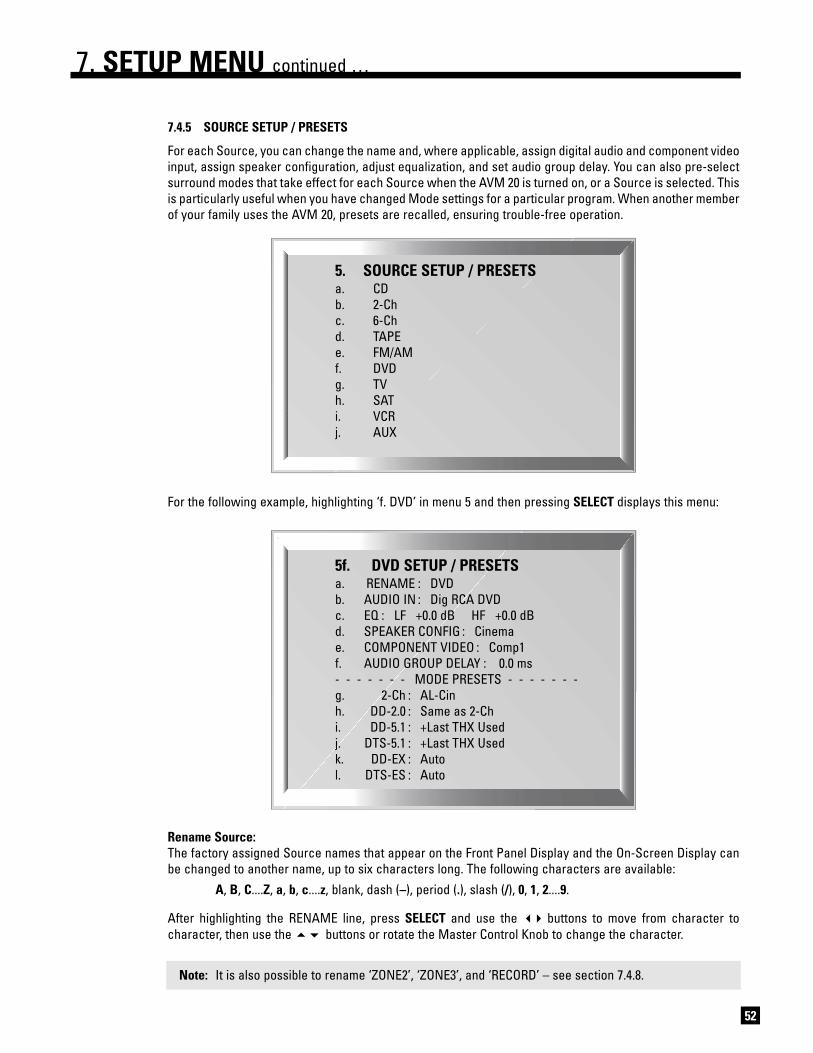
52
7.4.5 SOURCE SETUP / PRESETS
For each Source, you can change the name and, where applicable, assign digital audio and component videoinput, assign speaker configuration, adjust equalization, and set audio group delay. You can also pre-selectsurround modes that take effect for each Source when the AVM 20 is turned on, or a Source is selected. Thisis particularly useful when you have changed Mode settings for a particular program. When another memberof your family uses the AVM 20, presets are recalled, ensuring trouble-free operation.
For the following example, highlighting ‘f. DVD’ in menu 5 and then pressing SELECT displays this menu:
Rename Source:The factory assigned Source names that appear on the Front Panel Display and the On-Screen Display canbe changed to another name, up to six characters long. The following characters are available:
A, B, C....Z, a, b, c....z, blank, dash (–), period (.), slash (/), 0, 1, 2....9.
After highlighting the RENAME line, press SELECT and use the buttons to move from character tocharacter, then use the buttons or rotate the Master Control Knob to change the character.
Note: It is also possible to rename ‘ZONE2’, ‘ZONE3’, and ‘RECORD’ – see section 7.4.8.
7. SETUP MENU continued …
5. SOURCE SETUP / PRESETSa. CDb. 2-Chc. 6-Chd. TAPEe. FM/AMf. DVDg. TVh. SATi. VCRj. AUX
5f. DVD SETUP / PRESETSa. RENAME : DVDb. AUDIO IN : Dig RCA DVDc. EQ : LF +0.0 dB HF +0.0 dBd. SPEAKER CONFIG : Cinemae. COMPONENT VIDEO : Comp1f. AUDIO GROUP DELAY : 0.0 ms- - - - - - - MODE PRESETS - - - - - - -g. 2-Ch : AL-Cinh. DD-2.0 : Same as 2-Chi. DD-5.1 : +Last THX Usedj. DTS-5.1 : +Last THX Usedk. DD-EX : Autol. DTS-ES : Auto

53
7. SETUP MENU continued …
Audio In:There are four input formats to choose from – Digital, Analog-DSP, Analog-Direct, or Auto. After highlighting‘AUDIO IN’ use the buttons to select an input format.
Selections apply to the MAIN Path only:
• Dig (Digital – not applicable to 6-Ch S/E, 2-Ch BAL, or FM • AM): Use this setting for any sourcecomponent that has a digital output, especially the DVD player – Dolby Digital and DTS aretransmitted only through the digital connection.
• Anlg-DSP (Analog with Digital Signal Processing): If you want your subwoofer to play from ananalog L/R input, use this setting. Analog input is converted to digital through the AVM 20’s high-endA/D converters to enable bass management, time alignment, Mode, Bass/Treble, Audio GroupDelay, and THX. All of these are also available for the 6-Ch S/E input, since it can also be set to Anlg-DSP. With the bass management and time alignment that this provides, the resulting soundquality from DVD-Audio or multichannel SACD is far better than setting the 6-Ch input to Anlg-Dir.
• Anlg-Dir (Analog-Direct – not applicable to FM • AM): A/D conversion and Digital Signal Processingare bypassed, only leaving Volume, Surround Mode Level, Balance, and Mute functional. Other thanthe subwoofer channel of the 6-Ch S/E input, there is no subwoofer output in Anlg-Dir.
• Auto: The AVM 20 automatically switches between Digital and Analog-DSP. When it senses adigital bitstream, the Digital input is used. At all other times, it switches to the Analog L/R input. Thisfeature is especially useful with a digital cable box since some channels are broadcast digitallywhile others are analog – the AVM 20 switches automatically while you change channels.
Once you have set a Source to ‘Digital’ or ‘Auto’, press SELECT and then use the buttons choosethe connector that your source component is connected to – any RCA input, TOS1, TOS2, TOS3, or XLRcan be used. All digital input connectors can be assigned to multiple Sources – this allows you to havetwo unique Setup/Preset settings for the same DVD player, one for DVDs using the DVD Source, and theother for CD music using the CD Source.
EQ:For Sources set to Digital or Anlg-DSP, you can preset low and high frequency levels. This is useful for sourcecomponents that have frequency irregularities. After highlighting the EQ line, press SELECT and use thebuttons to select LF (low frequency) or HF (high frequency), then use the buttons to adjust. In theFM/AM Setup/Presets menu, FM and AM can be adjusted separately.
Note: The BASS and TREBLE buttons on Front Panel and Remote Control do not affect this menu, butallow ‘on-the-fly’ adjustment of program material as may be required (see section 5.7).
Speaker Configuration:Choose between Cinema (menu 2a.) or Music (menu 2b.) configuration – see section 7.4.2.
A third very unique choice is also available: Auto-LFE. When selected, the AVM 20 automatically uses theCinema configuration if there is LFE in the source material, and changes to the Music configuration at allother times. Highly recommended when using the same player for DVDs and CDs, and separate Cinema andMusic configurations. Dolby Pro Logic falls under Music configuration since it does not use an LFE track.
Component Video:Assign which Component video input (or ‘None’) is used when the Source is selected, for example, if yourDVD player is connected to Component1, select ‘Comp1’ in the DVD Setup/Presets menu. All Componentinputs can be assigned to multiple sources.

Program Preset Selections
• 2-Ch For stereo source material, select from any Mode described in section 5.8.3, or Last Used.In addition, Dolby Pro Logic, Pro Logic II-Movie, and Neo:6 Cinema can be preset eitherwith or without THX Cinema.
The following presets apply to Digital inputs only:
• DD-2.0 For two-channel Dolby Digital material, you can use the same selection as for stereosource material, Pro Logic II-Movie: Auto (see section 5.8.2) with or without THX Cinema,or Last Used.
• DD-5.1 Presets a THX mode for Dolby Digital 5.1 material: THX Cinema, THX Ultra2 Cinema, THXMusicMode, THX Surround EX, Off, or Last Used (see section 5.8.6).
• DTS-5.1 Presets a THX mode for DTS-5.1 material. THX Cinema, THX Ultra2 Cinema, THXMusicMode, Neo:6+THX, Off, or Last Used (see section 5.8.6).
• DD-EX For material encoded in Dolby Digital Surround EX. Select Dolby Digital EX: On, Auto, Off,or Last Used. It is also possible to set On or Auto together with THX Surround EX – thisallows automatic engagement of THX Surround EX for flagged Surround EX material whileengaging a different THX mode for non-flagged material (see section 5.8.4).
• DTS-ES For DTS-ES material. Select Neo: 6 On or Auto, with or without THX, or Last Used (seesection 5.8.5).
54
7. SETUP MENU continued …
Audio Group Delay:Using line doublers, quadruplers, or scalers causes the video to be delayed, which means that you will hearsound slightly ahead of seeing the video picture. This can also occur with HDTV and satellite broadcasts. Tocompensate for this video delay, Audio Group Delay can delay sound of all channels simultaneously by up to85 milliseconds – please check the owner’s manual for your doubler, quadrupler, or scaler for recommendeddelay settings. If you do not know the recommended delay settings, you can adjust Audio Group Delayoutside of the Setup Menu – this allows you to see the picture as you make adjustments (see section 6.7).
Mode Presets:You can pre-select the Mode and THX preference that will be applied when a Source is selected, or MAINpower is turned on. There are separate settings for each type of program material.
To disable a preset, set it to ‘Last Used’. Presets are not available for Sources set to Anlg-Dir.
For complete descriptions of surround modes and when to use them, refer to section 5.8.
Use the buttons to highlight one of the lines above in the menu, then use the buttons to scrollthrough the selections.
Certain combinations are not possible, for example, Dolby Digital EX can only take effect if THX is off. Shoulda conflict arise, the rules by which the AVM 20 overrides settings are as follows:
When THX is set to Cinema, Ultra2 Cinema, MusicMode, or Surround EX and...
• Dolby Digital EX is set to Off, then the selected THX mode takes effect.
• Dolby Digital EX is set to On, then THX Surround EX is automatically engaged.
• Dolby Digital EX is set to Auto and the source material has no Dolby Digital Surround EX flag, thenthe selected THX mode takes effect.
• Dolby Digital EX is set to Auto and the source material is flagged, then THX Surround EX isautomatically engaged.

55
7. SETUP MENU continued …
SOURCE SETUP/PRESET EXAMPLES
Example 1: Rename AUX to ‘GAME’.
• Enter the Setup (section 7.1). Go to ‘5. SOURCE SETUP / PRESETS’ and press SELECT.
• Press the button until you reach ‘j. AUX’ and press SELECT.
• ‘a. RENAME: AUX’ will be highlighted in red.
• Press SELECT. The first character ‘A’ will be highlighted in red.
• Use the Master Control Knob or the buttons to change characters. Change the first one to ‘G’.
• Press the button to move to the next character. Change it to ‘A’.
• Use the buttons to move to each remaining character. Change to ‘M’ and ‘E’.
• Press BACK to leave the submenu and return to the main menu.
Example 2: Change SAT Digital Input from ‘RCA’ to ‘Toslink1’ (TOS1).
• Make sure satellite receiver is connected to TOS1 and playing.
• Enter the Setup (section 7.1). Go to ‘5. SOURCE SETUP / PRESETS’ and press SELECT.
• Press the button until you reach ‘h. SAT’ and press SELECT.
• Press the button until you reach ‘b. AUDIO IN: Dig RCA DVD’ and press SELECT.
• ‘RCA DVD’ will be highlighted. Use the buttons to change to ‘TOS1’ (sound will now be heard).
• Press BACK to leave the submenu and return to the main menu.
Example 3: Adjust TAPE Source Equalization.
• Make sure TAPE source component is connected to Analog Inputs and playing.
• Enter the Setup (section 7.1). Go to ‘5. SOURCE SETUP / PRESETS’ and press SELECT.
• Press the button until you reach ‘d. TAPE’ and press SELECT.
• Press the button until you reach ‘c. EQ’ and press SELECT.
• Use the buttons to move to ‘LF’ or ‘HF’. Use the buttons to adjust.
• Press BACK to leave the submenu and return to the main menu.
Example 4: Set SAT Audio Group Delay to 60 milliseconds.
• Enter the Setup (section 7.1). Go to ‘5. SOURCE SETUP / PRESETS’ and press SELECT.
• Press the button until you reach ‘h. SAT’ and press SELECT.
• Press the button until you reach ‘f. AUDIO GROUP DELAY’ and press SELECT.
• Use the buttons to move from digit to digit and the buttons to adjust to ‘60 ms’.
• Press BACK to leave the submenu and return to the main menu.

56
7. SETUP MENU continued …
7.4.6 ADJUST INPUT LEVELSFor Sources set to Anlg-DSP or Anlg-Dir in menu 5, you can match input levels in MAIN to each other sothere are no large changes in volume as you change Sources.
If a source that is set to Analog-DSP is playing while you adjust the Input Level, you will notice a vertical bargraph to the left of the dB setting. With the On-Screen display, if this Bar Graph changes from green to pink,you have gone into an overload condition. Reduce the level until the bar graph changes back to green.
Before making changes or adjustments in this menu, have all connected source components playingsimilar music material. Then, as you switch through each highlighted Source, you will hear thatcomponent play. This lets you know that each component is connected to the AVM 20, and it also allowsfor easy comparative level adjustments of analog sources. Remember, adjusting input levels onlyfunctions with Sources set to Analog in menu 5, and the bar graph only works with Analog-DSP setting.
Example: Adjust TAPE Input Level.
• Make sure a source component is connected to TAPE Analog L/R Input and playing.
• Enter the Setup (section 7.1). Go to ‘6. ADJUST INPUT LEVELS’ and press SELECT.
• Press the button until you reach ‘d. TAPE: +0.0 dB’.
• Press SELECT. ‘+0.0 dB’ will be highlighted in red.
• Use the buttons to change the Level (keep the bar graph green).
• When finished, press BACK and then to go to another Source, or...
• Press BACK to leave the submenu and return to the main menu.
6. ADJUST INPUT LEVELSAdjustment only applies whenAudio-In is set to Analog
a. CD : +0.0 dBb. 2-Ch : +0.0 dBc. 6-Ch : +0.0 dBd. TAPE : +0.0 dBe. FM/AM : –5.0 dBf. DVD : +0.0 dBg. TV : +0.0 dBh. SAT : +0.0 dBi. VCR : +0.0 dBj. AUX : +0.0 dB

57
7. SETUP MENU continued …
7.4.7 A-D/AUDIO-OUT FORMATIn the A-D/Audio-Out Format menu you can re-configure the Surround and Rear channels, set analog todigital conversion parameters for the digital Record output, and configure the balanced analog outputs.
Reverse Surrounds/Rears:If you’re using a 7.1 speaker system and prefer the Rear speakers instead of the Surrounds when 6-Ch S/Eis selected, set REVERSE SUR/REAR to ‘Yes’ and re-connect the AVM 20 as follows: Surround outputs on theAVM 20 to the Rear inputs on your amplifier, and the Rear AVM 20 outputs to the Surround amplifier inputs.The 6-Ch Surround inputs will now play through your Rear speakers. The AVM 20 flips the SUR/REARchannels back to normal whenever THX is turned on for the 6-Ch input or when any other input is selected,thereby maintaining correct speaker configuration at all times.
Copy Surrounds to Rears:When playing material or using a Mode that has Surround channel information but no Rear information,setting this to ‘Yes’ plays the Surround channel out of both sets of speakers.
Sampling Frequency (fs):When a Source that is set to Anlg-DSP is copied from MAIN to RECORD, the analog signal is converted todigital using the AVM 20’s high-end A/D converters, and sent to DIGITAL1. This is useful for recording analogmusic on a CD burner or computer with S/PDIF input on the sound card. You can select from 44.1, 48, 88.2, or96 kHz sampling rates. Recording level is set by the input level in menu 6 (see sections 5.2.1 and 7.4.6).
This is also the signal processing rate for MAIN. Other than AnthemLogic, certain surround Modes donot function when ‘2-Ch Anlg-DSP fs’ is set to 88.2 or 96 kHz. Therefore leave this set to 44.1 or 48 kHzunless a recording is being made, and then use 48, 88.2, or 96 kHz only if the equipment connected toDIGITAL1 and DIGITAL2 is capable of accepting those sampling rates.
For the 6-Ch S/E input, a separate setting is used so that bass management, time alignment, Mode,Bass/Treble, Audio Group Delay, and THX can be performed at the same high resolution that DVD-Audio andSACD provide. When 6-Ch S/E is copied from MAIN to RECORD, the DIGITAL1 output is a 2-channel downmix.
Bit Rate of DIGITAL1 when MAIN is copied to REC:Choose from 16 or 24 bit output, to match the recorder. At 16 bits, dither is added to improve low level signals.
Output of DIGITAL2:Set it to have the same output as DIGITAL1, or a fixed output from any Source set to Digital (DVD, SAT, etc.).DIGITAL1 and DIGITAL2 transmit data from digital sources in the same format it comes in – if it’s Dolby Digitalor DTS encoded, it stays that way and can be linked to other digital equipment.
Balanced Output:If the Balanced CENTER2 and SUB2 outputs are not in use for a second Center channel or Subwoofer inMAIN, they can be used as Balanced ZONE2 L/R outputs (see section 4.2.5).
7. A-D/AUDIO-OUT FORMATSee OPERATING MANUAL for
detailed instructionsa. 6-Ch REVERSE SUR/REAR : Nob. COPY SUR TO REAR : Noc. 6-ch Anlg-DSP fs : 96 kHzd. 2-ch Anlg-DSP fs : 44.1 kHze. DIG1 when -MAIN->REC : 24 Bitf. DIGITAL2 : Digital 1g. BAL OUT : Ctr2/Sub2

58
7. SETUP MENU continued …
7.4.8 VOLUMES / RENAME PATHS
This menu allows you to define the power-on volume settings, set whether or not MAIN outputs shut offwhen headphones are used, and to rename ZONE2, ZONE3, and RECORD.
Mute Amount:When MUTE is pressed, sound can cut out completely, or decrease in volume by the amount that you set tokeep some of it in the background – select from ‘Silent’, or –5 to –30 dB in 5 dB steps.
Power-On Volume:When you turn MAIN, ZONE2, or ZONE3 on, or plug in your headphones, the volume for each will come onat the known levels you have set in this menu. This avoids any potential ‘surprises’ of not knowing the volumesomeone had set when turning the AVM 20 off, and then having the power-on volume be either too loud orquiet. You can set independent volumes for MAIN, ZONE2, ZONE3, and HEADPHONE.
Maximum Volume:These settings allow you to individually limit the volume of MAIN, ZONE2, ZONE3, or HEADPHONE to avoiddamaging your equipment and/or your ears. This can also serve as a parental volume control feature. Therange of settings available for MAIN is from –95.5 dB to +31.5 dB in steps of .5 dB, and for ZONE2, ZONE3,and HEADPHONE, the range is from –70.0 dB to +10.0 dB in 1.25 dB steps.
To set a fixed output for ZONE2 or ZONE3, scroll MAX VOL past +10.0 dB to set ‘LockOnVol’ and then set thedesired fixed output level in ON VOL. When the Path is on, ‘Lock’ is displayed beside the volume readout toindicate that its volume cannot be changed with the volume control.
Headphone Mutes Speakers:Determines whether or not the MAIN speakers turn off when headphones are plugged into the Front Panel:
• ‘Yes’ The MAIN speakers mute. “HPHONE” is displayed instead of “MAIN” to indicate thatadjusting Volume, Bass, Treble, and Balance affect HEADPHONE only.
• ‘No’ MAIN speakers continue to play when headphones are plugged in. (To make headphoneadjustments see sections 5.2 to 5.7.)
Rename Path:The factory assigned Path names that appear on the Front Panel and On-Screen displays can be changed toanother name up to six characters long – procedure is the same as Rename Source (section 7.4.5).
8. VOLUMES / RENAME PATHSa. MUTE LEVEL : Silentb. MAIN ON VOLUME : –35.0 dBc. MAIN MAX VOLUME : +10.0 dBd. ZONE2 ON VOL : –35.0 dBe. ZONE2 MAX VOL : +0.0 dBf. ZONE3 ON VOL : –35.0 dBg. ZONE3 MAX VOL : +0.0 dBh. HPHONE ON VOL : –20.0 dBi. HPHONE MAX VOL : +0.0 dBj. HPHONE MUTE SPK : Nok. RENAME ZONE2 : ZONE2l. RENAME ZONE3 : ZONE3m. RENAME RECORD : RECORD

59
7. SETUP MENU continued …
7.4.9 TRIGGERS / IR / RS-232
When a trigger output on the AVM 20 is connected to the trigger input of another component, such as apower amplifier or video projector, the AVM 20 can turn the component on or off according to the trigger’sSetup. For components that do not use triggers, a triggerable power bar may work (see your dealer).
• Trigger1 and Trigger2: Provide standard trigger output of 12 volts with up to 50 mA of current,suitable for typical source components and most amplifiers.
• Trigger3: Provides an output of 12 volts with up to 200 mA of current, suitable for triggers onmotorized projection equipment and very high power amplifiers.
There is a quarter of a second delay between each trigger to minimize momentary line voltage drops causedby switching on too many devices at the same time.
All Triggers: Allows you to ‘Enable’ or ‘Disable’ all trigger options regardless of their settings. For custom installations,‘RS-232 Ctrl’ defeats the settings and allows external control over all triggers.
Set Trigger: Highlighting ‘b. SET TRIGGER 1’ and then pressing SELECT displays this menu – in the example shown,TRIGGER 1 activates whenever MAIN power is turned on:
Under each of the four AVM 20 Paths, MAIN, ZONE2 (Z2), ZONE3 (Z3), and RECORD (REC), notice that thereare 40 available Sources (40 dashes) that could be used to activate the trigger. After highlighting POWER ONor a Source, press SELECT and use the buttons to move from one Path to another, and then to set thetrigger to activate, use the buttons to change the ‘–’ to a ‘*’.
9. TRIGGERS / IR / RS-232a. ALL TRIGGERS : Disabledb. SET TRIGGER 1c. SET TRIGGER 2d. SET TRIGGER 3e. SET IR-INPUTSf. BAUD RATE : 19200g. FLOW CONTROL : Noneh. RS-232 TX STATUS : Off
9b. SET TRIG-1 SOURCES - 50mAMAIN Z2 Z3 REC
a. POWER ON : * – –b. CD : – – – –c. 2-Ch : – – – –d. 6-Ch : –e. TAPE : – – – –f. FM/AM : – – – –g. DVD : – – – –h. TV : – – – –i. SAT : – – – –j. VCR : – – – –k. AUX : – – – –

60
7. SETUP MENU continued …
Note: Changes to the trigger setup do not take effect until the Setup Menu is exited completely, to avoidunnecessary rapid turning off and on of triggers while changes are being made.
Set IR Inputs: This allows you to enable or disable the AVM 20’s Front IR Receiver and Rear IR Inputs. Being able to do socan be useful when an IR repeater, connected to the AVM 20, is located in the same room as the AVM 20. Insuch a case, the AVM 20 can receive two IR signals for the same command – one from the Remote Controland one from the repeater. The problem is that rear signal is delayed slightly, and may confuse the IRReceivers’ control circuits. Disabling the Front IR solves this problem.
In other situations, the IR signal may find its way to the internally mounted IR receiver through the vents inthe top cover. This could also cause confusion for the AVM 20. If the Rear IR inputs are not in use, simplydisable them to prevent any potential problems.
After highlighting an IR input, press SELECT and use the buttons to move from one Path to another. Toturn the input off, use the buttons to change the ‘*’ to a ‘–’. Do this through the Front Panel, sinceRemote Control commands are ineffective once an IR sensor is turned off.
Note: If the AVM 20 does not respond to Remote Control commands, check the FRONT IR menu – enterthe Setup using the Front Panel buttons, go to menu ‘9. TRIGGERS/IR/RS-232’, followed by ‘e. SET IR-INPUTS’, and make sure the FRONT IR settings are set to ‘*’.
Baud Rate and Flow Control: The Baud Rate (adjustable from 1200 to 115200 bps), and Flow Control (‘RTS’, ‘CTS’, or ‘None’), allowconfiguration of the serial port communication parameters (normally for use by dealer/installers only).
RS-232 TX Status: When ‘On’, all commands, status changes, and control information are echoed through the RS-232 port(normally for use by dealer/installers only).
Example: Activate Trigger1 when DVD is selected in MAIN.
• Enter the Setup (section 7.1). Go to ‘9. TRIGGERS/IR/RS-232’ and press SELECT.
• Upon entering this menu item, ‘a. ALL TRIGGERS: Disabled’ will be highlighted in red.
• Use the buttons to change to ‘Enabled’.
• Press the button to go to ‘b. SET TRIGGER 1. Press SELECT.
• Use the buttons to go to ‘DVD’. Press SELECT.
• Use the buttons to change the ‘–’ to ‘*’.
• Press BACK twice to leave this submenu.
9e. SET IR-INPUTSMAIN Z2 Z3
a. FRONT IR : * * *b. REAR IR 1 : * * *c. REAR IR 2 : * * *d. REAR IR 3 : * * *

61
7.4.10 DISPLAYS / TIMEOUT
This menu allows you to configure both the On-Screen display, Front Panel display and Selection Time.
Main / Z2 On-Screen: Lets you select the outputs that receive the On-Screen display – ‘Composite’, ‘S-Video’, or both. ‘Bypassed’turns the On-Screen display off; if you choose ‘Bypassed’, you will have to rely on the Front Panel display.
Note: On-Screen display is not available for Component Video.
Main / Z2 OS Info: From here, select the Path adjustments that are shown by the MAIN or ZONE2 On-Screen displays. Forexample, if ZONE2 is set up with an IR repeater for the Remote Control, and you are using the AVM 20 in theMAIN room, you may not want to be disturbed by information about adjustments made in ZONE2 by someoneelse. In a different situation, you may want to see the ZONE2 information, for example, while adjusting ZONE2yourself from the MAIN room.
Main / Z2 OS Position:Allows you to position the On-Screen display to reduce the chance of it interfering with the on-screendisplay positions of other video components (e.g. satellite receiver or a TV monitor’s own display, etc.).Choose from: ‘Bottom’, ‘Mid’, or ‘Top’.
Main / Z2 OS Color:If the On-Screen display of the Setup Menu appears unstable, it could be that your monitor is notsynchronizing to the blue (factory default) background color. You can change the background color to onethat your projector/monitor can synchronize to – black and magenta are also available.
Front Panel Brightness: Simultaneously adjusts the intensity level of the Front Panel display and LED indicators. Three separateadjustments can be made – HI, MED, and LOW when the DISPLAY button is used (section 5.9). Use HI to setthe daytime level, MED for the evening level and LOW for the nighttime level.
Front Panel Wake-Up:If Display is set to Medium, Low, or Off, it can be made to change to a brighter level while you make anyadjustment, to either one level higher or Hi – choose ‘None’, ‘Up 1’, or ‘Hi’. When ‘None’ is chosen and theDisplay is Off, it will behave as if set to ‘Up 1’ to prevent confusion as to whether the power is on or off.
7. SETUP MENU continued …
10. DISPLAYS / TIMEOUTa. MAIN ON-SCREEN : Comp + S-Vb. MAIN OS INFO : All Zonesc. MAIN OS POS’N : Bottomd. MAIN OS COLOR : Bluee. Z2 ON-SCREEN : Comp + S-Vf. Z2 OS INFO : Z2 Onlyg. Z2 OS POS’N : Bottomh. Z2 OS COLOR : Bluei. FRT PANEL-HI : 15j. FRT PANEL-MED : 10k. FRT PANEL-LOW : 5l. FP WAKE-UP : Up 1m. FUNCTION TIMEOUT : 5 s

62
Function Timeout: This is the time that elapses after any adjustment is made. Once the Function Time elapses, the On-Screentext disappears and the Front Panel display becomes dim. This also applies to how long ZONE2, ZONE3,RECORD, and HEADPHONE information is displayed before MAIN display information returns. You can setFunction Timeout between 1 and 15 seconds.
Example: Set the position of the MAIN On-Screen information to the middle of the monitor.
• Enter the Setup (section 7.1). Go to ‘10. DISPLAYS/TIMEOUT’ and press SELECT.
• Press the button until you reach ‘c. MAIN OS POS’N: Bottom’.
• Use the buttons to change to ‘Middle’.
• When finished, press to go to another menu item, or...
• Press BACK to leave the submenu and return to the main menu.
7. SETUP MENU continued …

63
7.4.11 SAVE / RESTORE SETTINGS
The AVM 20 enables you to save your entire Setup configuration. Two separate save files are provided: USERSETTINGS and INSTALLER SETTINGS. If your system is set up by your dealer, the configuration can be savedin the INSTALLER file by the dealer. You can then make further Setup adjustments – save those settingsseparately in your own USER file. FM • AM presets are also saved separately in USER SETTINGS andINSTALLER SETTINGS.
If someone makes unwanted changes to the Setup Menu of your AVM 20, you can quickly and easily restoreeither the dealer’s INSTALLER settings or your USER settings, thereby preventing the need to run through theSetup procedure all over again. FM • AM presets saved in USER SETTINGS or INSTALLER SETTINGS will alsobe restored.
The original FACTORY DEFAULTS can also be reloaded at any time to reset the AVM 20 to the factory settings.As well, surround mode level, balance and bass/treble adjustments described in sections 5.6 and 5.7 will bereset to 0 dB, and Mode settings described in section 5.8 will be reset to ‘None’ for all Sources.
Save Settings: You can save settings with or without the use of a Password. Passwords are very easy to set up (see section7.4.12) and will protect both USER and INSTALLER files from being changed by anyone who doesn’t have thePassword. New saves will overwrite the previously saved file. The AVM 20 will prompt you to confirm thatyou want to over-write currently saved settings – press BACK at this point to abort a save.
Restore or Reload Settings: You may RESTORE USER SETTINGS, INSTALLER SETTINGS, or RELOAD FACTORY DEFAULTS at will. TheAVM 20 will prompt you to confirm that you want to replace the current settings – press BACK at this pointto abort a restore.
Example 1: Save User Settings.
Note: FM • AM Tuner presets will also be saved in USER SETTINGS.
• Enter the Setup (section 7.1). Go to ‘11. SAVE/RESTORE SETTINGS’ and press SELECT.
• Upon entering this menu item, ‘a. SAVE USER SETTINGS’ will be highlighted in red.
• Press SELECT. You will be asked to confirm that you want to over-write current settings.
• Use the buttons and change to ‘Yes’. If you are using a Password (section 7.4.12), you will beasked for it. Use the 0 – 9 buttons to enter your Password. The On-Screen display message will thensay ‘Saving Successful’, the Front Panel display will say ‘Done!’.
• When finished, press to go to another menu item, or...
• Press BACK to leave the submenu and return to the main menu.
11. SAVE / RESTORE SETTINGSa. SAVE USER SETTINGSb. RESTORE USER SETTINGSc. SAVE INSTALLER SETTINGSd. RESTORE INSTALLER SET’NSe. RELOAD FACTORY DEFAULTS
7. SETUP MENU continued …

64
Example 2: Restore Installer Settings.
Note: FM • AM Tuner presets that were saved in INSTALLER SETTINGS will also be restored.
• Enter the Setup (section 7.1). Go to ‘11. SAVE/RESTORE SETTINGS’ and press SELECT.
• Press the button until you reach ‘d. RESTORE INSTALLER SET’NS’.
• Press SELECT. You will be asked to confirm that you want to restore installer settings.
• Use the buttons to change to ‘Yes’ and press SELECT. On-Screen display message will then say‘Saving Successful’, the Front Panel display will say ‘Done!’.
• When finished, press to go to another menu item, or...
• Press BACK to leave the submenu and return to the main menu.
Example 3: Reload Factory Defaults.
Note: The current time and FM • AM Tuner presets will be retained. Surround mode level, balance,bass/treble adjustments (sections 5.6 and 5.7), and Modes (section 5.8) will be reset to +0.0 dB.
• Enter the Setup (section 7.1). Go to ‘11. SAVE/RESTORE SETTINGS’ and press SELECT.
• Press the button until you reach ‘e. RELOAD FACTORY DEFAULTS’.
• Press SELECT. You will be asked to confirm that you want to ‘reload factory settings’.
• Use the buttons to change to ‘Yes’ and press SELECT. On-Screen display message will then say‘Saving Successful’, the Front Panel display will say ‘Done!’.
• When finished, press to go to another menu item, or...
• Press BACK to leave the submenu and return to the main menu.
7. SETUP MENU continued …

7.4.12 LOCKOUT / PASSWORDS
Passwords are used to protect the saved User and Installer settings. Once you have set a password, it canalso be used as a Lockout to prevent settings from being changed by anyone without one of the passwords.
Set Setup Menu Lockout: When set to ‘Yes’, this prevents anyone without a password from entering the Setup. When you attempt toenter the Setup, you will be asked for your Password – either the USER or INSTALLER Password must thenbe entered from the Remote Control before you will be allowed to continue.
Set User or Installer Password:When setting the USER or INSTALLER Password, you will be asked to enter a four digit number. Pick one thatyou will remember easily. To enter that number, use the 0 – 9 keys on the Remote Control (password cannotbe entered from the Front Panel). To change an existing password, enter the old one first, then enter (andconfirm) the new one.
Example 1: Set User Password (Remote Control only).
• Enter the Setup (section 7.1). You must enter the USER or INSTALLER Password if there is one.
• Go to ‘12. LOCKOUT/PASSWORDS’ and press SELECT.
• Press the key to go to ‘b. SET USER PASSWORD’.
• Press SELECT. You will be asked to enter a four digit number. Use the 0 – 9 keys to do so. If you arechanging your Password you will be asked to enter your old Password first. You will also be askedto confirm your new Password (re-enter your new Password).
• When finished, press to go to another menu item, or...
• Press BACK to leave the submenu and return to the main menu.
Clearing the User Password: When asked for your new Password, press the key four times. You willalso be asked to confirm your new Password – press the key four times again. Message will then say‘User Password Removed’.
Example 2: Set Setup Menu Lockout.
• Enter the Setup (section 7.1). Go to ‘12. LOCKOUT/PASSWORDS’ and press SELECT.
• Upon entering this menu item, ‘a. SET SETUP MENU LOCKOUT’ will be highlighted in red.
• Press SELECT. You will be asked to enter your Password. Either the USER or INSTALLER Passwordwill work. Use the 0 – 9 keys to do so.
• Use the buttons to change to ‘Yes’ or ‘No’.
• Press SELECT or BACK.
• When finished, press to go to another menu item, or...
• Press BACK to leave the submenu and return to the main menu.65
12. LOCKOUT / PASSWORDSa. SET SETUP MENU LOCKOUTb. SET USER PASSWORDc. SET INSTALLER PASSWORD
7. SETUP MENU continued …

66
8. SOFTWARE UPDATING
The operational characteristics of the AVM 20 are controlled by software that can be easily upgraded via theRS-232 port on the Rear Panel. New software can be downloaded from our web site, and then transferred byconnecting the AVM 20 to your computer’s serial port and running the Software Installer.
8.1 SOFTWARE VERSION IDENTIFICATION
If you want to see which Software Version is in your AVM 20, press STATUS. The display will show:
Please contact your dealer or visit the AVM 20 page on our web site at www.anthemAV.com to find the latestSoftware, and any operating manual updates that go along with new versions.
8.2 SOFTWARE UPDATING VIA YOUR DEALER
To do this, you will have to take your AVM 20 to your Authorized Anthem Dealer. To save yourself time andtrouble, please remember to call your dealer first to find out if you should get the latest Software version, andthen arrange a time to install the update. Note: Your dealer may charge for this service.
8.3 SOFTWARE UPDATING VIA YOUR COMPUTER AND THE INTERNET
To update the Software through your computer, you will need the following:
• Access to the Internet.
• Serial cable – straight wired, with one end DB9 male for the AVM 20, and the other, DB9 female orDB25 female for your computer. A similar looking null-modem cable will not work.
Typically, a cable length of up to 100 feet (33 meters) will work for a long distance connection to yourcomputer. You may also install this cable permanently to enable easy future updates. When it’s notin use, disconnecting it either behind the computer or the AVM 20 is recommended, to prevent thepossibility of a ground loop.
Computer System Requirements:
• Win9x, NT, ME, 2000, or XP.
• 1 MB free space on the hard drive.
• Serial port. The Software Installer automatically detects the port being used (COM1 to COM4).If your computer does not have a serial port but has a USB port, you will need a USB-to-serialadapter (its driver program must also be installed on your computer).
Note: Before running the Installer, check the computer’s power management settings to ensure that theSoftware Update does not get interrupted while running.

67
Software installation procedure:
1. Find out which Software version you currently have by pressing STATUS.
2. Go to the ANTHEM web site (www.anthemAV.com) and locate the latest AVM 20 Software version.Proceed only if your version is a lower number, indicating that it is older.
3. Click on the download icon. You will be asked where to save a file called ‘avm20install.zip’ – save itto your computer’s desktop.
4. Double click on ‘avm20install.zip’. If you computer tells you that the file cannot be opened, you candownload a program that can open the file through one of the links on the ANTHEM web site.
5. Drag or extract ‘AVM 20 Installer.exe’ and ‘Read Me First.txt’ to desktop. ‘Read Me First.txt’ lists thelatest software changes. You can now delete ‘avm20install.zip’.
6. Ensure that your current AVM 20 Setup configuration is saved (see section 7.4.11).
7. Turn off your AVM 20 and disconnect the power cord to prevent the possibility of a static dischargewhen the serial port is connected. Tuner presets, speaker level settings, bass/treble, etc. areautomatically written to memory if the line voltage is disconnected or during a power failure.
8. Using the serial cable, connect your computer to the AVM 20 via the RS-232 port on the rear panel.Updating does not require moving the AVM 20 or disconnecting it from your system, as long as youcan connect your computer to the RS-232 port.
9. Plug the AVM 20’s power cord back in and turn the rear panel switch on.
10. Double click on ‘AVM 20 Installer.exe’, then click on ‘Install Upgrade Now’. In a few minutes, theinstallation and verification will be completed.
Restore Settings?You do not need to Restore or Recall any settings after installing new software. The AVM 20 will retain thesettings that were in use before the update, except that the day and time will be set according to yourcomputer’s day and time settings – if re-adjustment is required, see section 7.4.1.
Troubleshooting:If the Installer keeps returning a message that says ‘AVM 20 Not Found’ after several attempts, restoreFactory Defaults in the Setup Menu, try installing again, and reload User Settings once the new software isinstalled. If that doesn’t work, make sure that the serial port on your computer isn't already being used byanother application, such a docking station for a personal organizer – you must go into the application thatis using it to turn off the serial port.
8. SOFTWARE UPDATING continued …

68
DIRECT MODE/BANK ACCESS:
Using the AVM 20 IR codes forMAIN Path, the following 3-keysequences can be programmed intomacro-capable remotes for directaccess to Modes and tuner banks:
For Stereo Sources:MODE, 0, 1 – StereoMODE, 0, 2 – AnthemLogic-MusicMODE, 0, 3 – AnthemLogic-CinemaMODE, 0, 4 – Pro Logic II-MusicMODE, 0, 5 – Pro Logic II-MovieMODE, 0, 6 – Dolby Pro LogicMODE, 0, 7 – DTS Neo:6-MusicMODE, 0, 8 – DTS Neo:6-CinemaMODE, 0, 9 – All-Channel StereoMODE, 1, 0 – All-Channel MonoMODE, 1, 1 – MonoMODE, 1, 2 – Mono-Academy
THX, 0, 1 – THX Cinema OffTHX, 0, 2 – THX Cinema On
For Dolby D-2.0 Sources:MODE, 2, 1 – StereoMODE, 2, 2 – AnthemLogic-MusicMODE, 2, 3 – AnthemLogic-CinemaMODE, 2, 4 – Pro Logic II-MusicMODE, 2, 5 – Pro Logic II-MovieMODE, 2, 6 – Dolby Pro LogicMODE, 2, 7 – DTS Neo:6-MusicMODE, 2, 8 – DTS Neo:6-CinemaMODE, 2, 9 – All-Channel StereoMODE, 3, 0 – All-Channel MonoMODE, 3, 1 – MonoMODE, 3, 2 – Mono-Academy
MODE, 3, 7 – Pro Logic II-Movie OffMODE, 3, 8 – Pro Logic II-Movie OnMODE, 3, 9 – Pro Logic II-Movie Auto
THX, 0, 3 – THX Cinema OffTHX, 0, 4 – THX Cinema On
Pro Logic II-Music Adjustment:MODE, 4, 1 – Center Width displayMODE, 4, 2 – Dimension displayMODE, 4, 3 – Panorama OffMODE, 4, 4 – Panorama On
Neo:6-Music Adjustment:MODE, 4, 5 – Center Image display
For Dolby D-5.1 Sources:MODE, 5, 1 – Dolby Digital EX OffMODE, 5, 2 – Dolby Digital EX OnMODE, 5, 3 – Dolby Digital EX Auto
THX, 1, 0 – THX OffTHX, 1, 1 – THX CinemaTHX, 1, 2 – THX Ultra2 CinemaTHX, 1, 3 – THX MusicModeTHX, 1, 4 – THX Surround EX
For DTS Sources:MODE, 6, 1 – Neo:6 OffMODE, 6, 2 – Neo:6 On
THX, 2, 0 – THX OffTHX, 2, 1 – THX CinemaTHX, 2, 2 – THX Ultra2 CinemaTHX, 2, 3 – THX MusicModeTHX, 2, 4 – THX for DTS-ES
THX Re-Eq:THX, 3, 0 – Re-Eq OffTHX, 3, 1 – Re-Eq On
FM•AM Banks (ZONE2/3/REC codes also work):MODE, 9, 0 – AMMODE, 9, 1 – FM1MODE, 9, 2 – FM2MODE, 9, 3 – FM3
MANUFACTURER’S CODES:
Statement D1 and AVM 20 – MAIN 0040Statement D1 and AVM 20 – ZONE2 0041Statement D1 and AVM 20 – ZONE3 0042AVM 2 – MAIN 0043AVM 2 – ZONE2 0044CD 1 0897Sonic Frontiers SFT 1 0157Sonic Frontiers SFCD 1 0157Sonic Frontiers Transport 3 0157
TVs:AOC 0030, 0019Admiral 0093, 0463Aiko 0092Akai 0030Alaron 0179Ambassador 0177America Action 0180Ampro 0751Anam 0180Audiovox 0451,0180, 0092, 0623Baysonic 0180Belcor 0019Bell & Howell 0154, 0016Bradford 0180Brockwood 0019Broksonic 0236, 0463CXC 0180Candle 0030, 0056Carnivale 0030Carver 0054Celebrity 0000Cineral 0451, 0092Citizen 0060, 0030, 0056, 0039,
0092Concerto 0056Contec 0180Craig 0180Crosley 0054Crown 0180, 0039Curtis Mathes 0047, 0054, 0154, 0051,
0451, 0093, 0060, 0030,0145, 0056, 0016, 0039,0166, 0466, 1147, 1347
Daewoo 0451, 0019, 0039, 0092,0623, 0624
Daytron 0019Denon 0145Dumont 0017, 0019Dwin 0720, 0774Electroband 0000Emerson 0154, 0236, 0463, 0180,
0282, 0178, 0019, 0179,0039, 0177, 0623, 0624
Envision 0030Fisher 0154Fujitsu 0179Funai 0180, 0179, 0171Futuretech 0180GE 0047, 0051, 0451, 0093,
0282, 0178, 0021, 0135,1147, 1347
Gibralter 0017, 0030, 0019GoldStar 0030, 0178, 0019, 0056Gradiente 0053, 0056Grunpy 0180, 0179Hallmark 0178Harley Davidson 0179Harman/Kardon 0054Harvard 0180Hitachi 0145, 0056, 0151Infinity 0054Inteq 0017JBL 0054JCB 0000JVC 0053KEC 0180KTV 0180, 0030, 0039Kenwood 0030, 0019LG 0056
LXI 0047, 0054, 0154, 0156,0178
Logik 0016Luxman 0056MGA 0150, 0030, 0178, 0019MTC 0060, 0030, 0019, 0056Magnavox 0054, 0030, 0179Majestic 0016Marantz 0054, 0030Matsushita 0250Megatron 0178, 0145Memorex 0154, 0250, 0463, 0150,
0178, 0056, 0016Midland 0047, 0017, 0051, 0039,
0135Minutz 0021Mitsubishi 0093, 0150, 0178, 0019Motorola 0093Multitech 0180NAD 0156, 0178, 0166NEC 0030, 0019, 0056NTC 0092Nikko 0030, 0178, 0092Onwa 0180Optimus 0154, 0250, 0166Optonica 0093, 0165Orion 0236, 0463, 0179Panasonic 0051, 0250Penney 0047, 0156, 0051, 0060,
0030, 0178, 0021, 0019,0056, 0039, 0135, 1347
Philco 0054, 0463, 0030, 0145,0019
Philips 0054Pilot 0030, 0019, 0039Pioneer 0166Portland 0019, 0039, 0092Prism 0051Proscan 0047Proton 0178, 0466Pulsar 0017, 0019Quasar 0051, 0250, 0165RCA 0047, 0051, 0093, 0019,
0090, 0135, 1047, 1147,1247, 1347
Radio Shack 0047, 0154, 0165, 0180,0030, 0178, 0019, 0056,0039
Realistic 0154, 0165, 0180, 0030,0178, 0019, 0056, 0039
Runco 0017, 0030, 0603SSS 0180, 0019Sampo 0030, 0039Samsung 0060, 0030, 0178, 0019,
0056Samsux 0039Sansei 0451Sansui 0463Sanyo 0154Scimitsu 0019Scotch 0178Scott 0236, 0180, 0178, 0019,
0179Sears 0047, 0054, 0154, 0156,
0178, 0179, 0056, 0171Semivox 0180Semp 0156Sharp 0093, 0165, 0039Shogun 0019Signature 0016Sony 0000Soundesign 0180, 0178, 0179Squareview 0171Starlite 0180Supreme 0000Sylvania 0054, 0030Symphonic 0171TMK 0178, 0056, 0177Tandy 0093Technics 0051, 0250Technol Ace 0179Techwood 0051, 0056Teknika 0054, 0180, 0150, 0060,
0019, 0179, 0056, 0016,0039, 0092
APPENDIX A - REMOTE CONTROL CODES

69
APPENDIX A - REMOTE CONTROL CODES continued …
Telefunken 0056Toshiba 0154, 0156, 0060Totevision 0039Vector Research 0030Victor 0053Vidikron 0054Vidtech 0178, 0019Wards 0054, 0165, 0030, 0178,
0021, 0019, 0179, 0056,0016
White Westinghouse 0463, 0623, 0624Yamaha 0030, 0019Zenith 0017, 0463, 0016, 0092
VCRs:Admiral 0048, 0209Adventura 0000Aiko 0278Aiwa 0037, 0000Akai 0041America Action 0278American High 0035Asha 0240Audiovox 0037Beaumark 0240Bell & Howell 0104Brocksonic 0209Broksonic 0184, 0121, 0209, 0002CCE 0072, 0278Calix 0037Canon 0035Carver 0081Cineral 0278Citizen 0037, 0278Colt 0072Craig 0037, 0047, 0240, 0072,
0271Curtis Mathes 0060, 0035, 0041, 0162Cybernex 0240Daewoo 0045, 0278Denon 0042Dynatech 0000Electrohome 0037Electrophonic 0037Emerex 0032Emerson 0037, 0184, 0000, 0121,
0043, 0209, 0002, 0278Fisher 0047, 0104Fuji 0035, 0033Funai 0000GE 0060, 0035, 0048, 0240Garrard 0000Go Video 0526GoldStar 0037, 0038Gradiente 0000HI-Q 0047Harley Davidson 0000Harman/Kardon 0081, 0038Harwood 0072Headquarter 0046Hitachi 0000, 0042, 0041Hughes Net. Sys. 0042JVC 0067, 0041Jensen 0041KEC 0037, 0278KLH 0072Kenwood 0067, 0041, 0038Kodak 0035, 0037LXI 0037Lloyd’s 0000Logik 0072MEI 0035MGA 0240, 0043MGN Technology 0240MTC 0240, 0000Magnasonic 0278Magnavox 0035, 0039, 0081, 0000,
0149Magnin 0240Marantz 0035, 0081Marta 0037Matsushita 0035, 0162, 0454Memorex 0035, 0037, 0048, 0039,
0047, 0240, 0000, 0104,
0209, 0046, 1162, 1262Minolta 0042Mitsubishi 0048, 0067, 0043Motorola 0035, 0048Multitech 0000, 0072NEC 0104, 0067, 0041, 0038Nikko 0037Noblex 0240Olympus 0035Optimus 0037, 0048, 0104, 0162,
0454, 1062, 1162, 1262Orion 0184, 0209, 0002Panasonic 0035, 0162, 0225, 0454,
1162Penney 0035, 0037, 0240, 0042,
0038Pentax 0042Philco 0035, 0209Philips 0035, 0081Pilot 0037Pioneer 0067Profitronic 0240Proscan 0060Protec 0072Pulsar 0039Quarter 0046Quartz 0046Quasar 0035, 0162, 0454, 1162RCA 0060, 0035, 0048, 0240,
0042, 0149Radio Shack 0000Radix 0037Randex 0037Realistic 0035, 0037, 0048, 0047,
0000, 0104, 0046
Runco 0039STS 0042Samsung 0240, 0045Sanky 0048, 0039Sansui 0000, 0067, 0209, 0041,
0271Sanyo 0047, 0240, 0104, 0046Scott 0184, 0045, 0121, 0043Sears 0035, 0037, 0047, 0000,
0042, 0104, 0046Semp 0045Sharp 0048Shintom 0072Shogun 0240Singer 0072Sony 0035, 0032, 0000, 0033Sylvania 0035, 0081, 0000, 0043Symphonic 0000TMK 0240Tatung 0041Teac 0000, 0041Technics 0035, 0162Teknika 0035, 0037, 0000Thomas 0000Toshiba 0045, 0043Totevision 0037, 0240Unitech 0240Vector 0045Vector Research 0038Video Concepts 0045Videosonic 0240Wards 0060, 0035, 0048, 0047,
0081, 0240, 0000, 0042,0072, 0149
White Westinghouse 0209, 0278XR-1000 0035, 0000, 0072Yamaha 0038Zenith 0039, 0000, 0209, 0033
TV/VCR Combos:American High 0035 (TV - 0051)Brocksonic 0002, 0294Colt 0072Curtis Mathis 0035 (TV - 0051)Daewoo 0278Emerson 0002, 0294, 0479Funai 0000GE 0035 (TV - 0051),
0060 (TV - 0047), 0048 (TV - 0093),0240
Hitachi 0035 (TV - 0051),0000
HQ 0000Lloyds 0000MGA 0240Magnavox 0081 (TV - 0054),
0035 (TV - 0051),0000
Magnin 0240Memorex 0037,
0162 (TV - 0250)Mitsubishi 0048 (TV - 0093)Orion 0002, 0294, 0479Panasonic 0035 (TV - 0051),
0162 (TV - 0250)Penney 0035 (TV - 0051),
0240,0162 (TV - 0250)
Quasar 0035 (TV - 0051),0162 (TV - 0250)
RCA 0060 (TV - 0047), 0035 (TV - 0051), 0048 (TV - 0093)
Sansui 0000, 0479Sanyo 0240Sears 0000, 0037Sharp 0048 (TV - 0093)Sony 0032 (TV - 0000)Symphonic 0000Zenith 0000
Cable Converters:ABC 0003, 0008, 0014, 0017,
0007, 0011, 0013Allegro 0153, 0315Archer 0153, 0797Bell & Howell 0014Century 0153Citizen 0153, 0315Comtronics 0040Contec 0019Eastern 0002Emerson 0797Everquest 0015,0040Focus 0400Garrard 0153Gemini 0015General Instrument 0476, 0276, 0011, 0810GoldStar 0144, 0040Goodmind 0797Hamlin 0020, 0259, 0009, 0034Hitachi 0011Hytex 0007Jasco 0015, 0153, 0315Jerrold 0003, 0012, 0476, 0276,
0014, 0015, 0011, 0810Memorex 0000Movie Time 0063NSC 0063Oak 0019, 0007Optimus 0021Panasonic 0000, 0107, 0021Paragon 0000Philips 0153Pioneer 0144, 0533Popular Mechanics 0400Pulsar 0000Quasar 0000RCA 0021Radio Shack 0015, 0315, 0797, 0883Recoton 0400Regal 0020, 0259Regency 0002Rembrandt 0011Runco 0000SL Marx 0040Samsung 0144, 0040Scientific Atlanta 0008, 0477, 0017, 0877Signal 0015, 0040Signature 0011Sprucer 0021

70
APPENDIX A - REMOTE CONTROL CODES continued …
Starcom 0003, 0015Stargate 0015, 0040, 0797Starquest 0015TV86 0063Teleview 0040Tocom 0012, 0013Toshiba 0000Tusa 0015Unika 0153United Artists 0007Universal 0153, 0191Viewstar 0063Zenith 0000, 0525Zentek 0400
Satellite or DBS Receivers:AlphaStar 0772Chaparral 0216Echostar 0775Expressvu 0775General Instrument 0627, 0361, 0869HTS 0775Hitachi 0819Hughes Net. Sys. 0749JVC 0775Jerrold 0627, 0361Magnavox 0724, 0722Memorex 0724Next Level 0869Panasonic 0701Philips 0724, 0722Primestar 0627, 0361RCA 0566, 0143, 0392, 0855Radio Shack 0869Realistic 0052Sony 0639Star Choice 0869Toshiba 0790Uniden 0724, 0722, 0052Zenith 0856
CD Players:Aiwa 0157, 0124Burmester 0420California Audio Lab 0029Carver 0157, 0179, 0437DKK 0000Denon 0003, 0873Emerson 0305Fisher 0179, 0174Garrard 0420, 0393Genexxa 0032, 0305Harman/Kardon 0157, 0173Hitachi 0032JVC 0072Kenwood 0028, 0037, 0190, 0681,
0826Krell 0157LXI 0305Linn 0157MCS 0029MTC 0420Magnavox 0157, 0305Marantz 0029, 0157, 0180Mission 0157NSM 0157Nikko 0174Onkyo 0101, 0868Optimus 0000, 0032, 0179, 0305,
0037, 0420, 0145, 0468,0437
Panasonic 0029, 0303Parasound 0420Philips 0157, 0626Pioneer 0032, 0305, 0468, 0244Proton 0157QED 0157Quasar 0029RCA 0179, 0305, 0053, 0764Realistic 0179, 0420, 0180Rotel 0157, 0420SAE 0157Sansui 0157, 0305Sanyo 0179
Scott 0305Sears 0305Sharp 0037, 0180, 0861Sherwood 0180Sony 0000, 0185, 0490Soundesign 0145Tascam 0420Teac 0420, 0393, 0174, 0180Technics 0029, 0303Victor 0072Wards 0157, 0053Yamaha 0036, 0187Yorx 0461
DVD Players:Harman/Kardon 0582JVC 0558Kenwood 0534Magnavox 0503Mitsubishi 0521Onkyo 0503Panasonic 0490Philips 0503, 0539Pioneer 0525, 0571Proscan 0522RCA 0522Samsung 0573Sony 0533Technics 0490Theta Digital 0571Toshiba 0503Yamaha 0490, 0545Zenith 0503, 0591
LD Players:Denon 0059Mitsubishi 0059NAD 0059Pioneer 0059Sony 0193, 0201
Cassette Decks:Aiwa 0029, 0197Carver 0029Denon 0076Harman/Kardon 0182, 0029JVC 0244, 0273Kenwood 0070Magnavox 0029Marantz 0029Onkyo 0135, 0282Optimus 0027, 0220Panasonic 0229Philips 0029Pioneer 0027, 0220, 0099Sansui 0029Sony 0243, 0170, 0291Technics 0229Victor 0273Wards 0027Yamaha 0097, 0094
Stereo Tuners or Receivers:ADC 0531Adcom 0616Aiwa 0158, 0189, 0121, 0405Akai 0224Capetronic 0531Carver 0189, 0008, 0042, 0360Casio 0195Clarinette 0195Curtis Mathes 0080Denon 0004Emerson 0424Fisher 0042, 0219, 0360Garrard 0463, 0424Harman/Kardon 0110, 0189, 0891JBL 0110JVC 0074Kenwood 0027, 0186, 0042, 0077Koss 0424LXI 0181Linn 0189
Lloyd’s 0195MCS 0039, 0346Magnavox 0531, 0189, 0195, 0391Marantz 0039, 0189Modulaire 0195NAD 0320Nakamichi 0097, 0347Onkyo 0135Optimus 0531, 0670, 0186, 0042,
0177, 0181, 0219, 0738,0801, 1023
Panasonic 0039, 0309Penney 0195Philips 0189, 0391Pioneer 0531, 0014, 0150, 0630,
0080, 1023Quasar 0039RCA 0531, 0054, 0346, 0360,
0530Realistic 0195, 0163, 0181Sansui 0189, 0346Sanyo 0219, 0801Scott 0163, 0322Sharp 0186Sherwood 0491, 0502Sony 0158, 0168, 0474Soundesign 0670Teac 0463, 0163Technics 0039, 0309, 0208Victor 0074Wards 0158, 0014, 0189, 0080,
0054Yamaha 0176, 0186Yorx 0195Zenith 0857
Stereo Amplifiers:Aiwa 0406Carver 0269Curtis Mathes 0300Denon 0160Harman/Kardon 0892JVC 0331Linn 0269Magnavox 0269Marantz 0269Panasonic 0308Philips 0269, 0892Pioneer 0013, 0300Sony 0220, 0689Technics 0308Victor 0331Wards 0013Yamaha 0354
Home Automation:GE 0240Lutron 0597One For All 0167Radio Shack 0240Security System 0167Universal X10 0167X10 0167
DBS Audio Services:Aiwa 0010, 0159, 0404Fisher 0052Harman/Kardon 0477JBL 0477JVC 0073Jerrold 0459, 0520RCA 0056Scientific Atlanta 0460Sony 0010, 0159Starcom 0459
Video Accessories:Archer 0160GC Electronics 0160Jebsee 0160Rabbit 0081Radio Shack 0160TeleCaption 0171

71
ANALOG AUDIO SECTION
Input Impedance . . . . . . . . . . . . . . . . . . . . . . . . . . . . . . . . . . . . . . . . . . . . . . . . . . . . . . . . . . . . . . . . . . . 20 kΩ
Output ImpedanceMain . . . . . . . . . . . . . . . . . . . . . . . . . . . . . . . . . . . . . . . . . . . . . . . . . . . . . 300 Ω (RCA), 600 Ω (XLR)Zone2/3 & Record . . . . . . . . . . . . . . . . . . . . . . . . . . . . . . . . . . . . . . . . . . . . . . . . . . . . . . . . . . . 51 Ω
Rated Input . . . . . . . . . . . . . . . . . . . . . . . . . . . . . . . . . . . . . . . . . . . . . . . . . . . . . . . . . . . . . . . . . . . . . 2.0 Vrms
Maximum Input6-Channel S/E . . . . . . . . . . . . . . . . . . . . . . . . . . . . . . . . . . . . . . . . . . . . . . . . . . . . . . . . . . . 3.0 VrmsAll Others . . . . . . . . . . . . . . . . . . . . . . . . . . . . . . . . . . . . . . . . . . . . . . . . . . . . . . . . . . . . . . . 5.3 Vrms
Rated Output (100 kΩ load) . . . . . . . . . . . . . . . . . . . . . . . . . . . . . . . . . . . . . . . . . . . . . . . . . . . . . . . . 2.0 Vrms
Minimum Load . . . . . . . . . . . . . . . . . . . . . . . . . . . . . . . . . . . . . . . . . . . . . . . . . . . . . . . . . . . . . . . . . . . . . 5 kΩ
Maximum OutputRCA. . . . . . . . . . . . . . . . . . . . . . . . . . . . . . . . . . . . . . . . . . . . . . . . . . . . . . . . . . . . . . . . . . . . 6.3 VrmsXLR . . . . . . . . . . . . . . . . . . . . . . . . . . . . . . . . . . . . . . . . . . . . . . . . . . . . . . . . . . . . . . . . . . . 12.6 Vrms
Headphone Output. . . . . . . . . . . . . . . . . . . . . . . . . . . . . . . . . . . . . . . . . . 100 mW into 32 Ω at 0.2% THD+N
Volume Control RangeMain . . . . . . . . . . . . . . . . . . . . . . . . . . . . . . . . . . . . . . . . . . -95.5 to +31.5 dB in 0.5 dB incrementsZone2/3 and Headphone. . . . . . . . . . . . . . . . . . . . . . . . . -70.0 to +10.0 dB in 1.25 dB increments
Channel Separation (at 1 kHz) . . . . . . . . . . . . . . . . . . . . . . . . . . . . . . . . . . . . . . . . . . . . . . . . . . . . . . . . 82 dB
Crosstalk Between Inputs (at 1 kHz). . . . . . . . . . . . . . . . . . . . . . . . . . . . . . . . . . . . . . . . . . . . . . . . . . . 86 dB
XLR Pin Configuration . . . . . . . . . . . . . . . . . . . . . . . . . . . . . Pin 1: Ground, Pin 2: Positive, Pin 3: Negative
DIGITAL AUDIO SECTION
Analog to Digital Converters. . . . . . . . . . . . . . . . . . . . . . . . . . . . . . . . . . . . . . . . . . . . . . . . . . . AKM AK5383
Processor . . . . . . . . . . . . . . . . . . . . . . . . . . . . . . . . . . . . . . . . . . . . . . . . . . . . . . Motorola 56367 at 150 MHz
Digital to Analog Converters. . . . . . . . . . . . . . . . . . . . . . . . . . . . . . . . . . . . . . . . . . . . . . . . . . . AKM AK4382
CrossoverHigh-Pass Slope (Small Speaker Setting) . . . . . . . . . . . . . . . . . . . . . . 12 dB/octave (2nd order)Low-Pass Slope (Subwoofer) . . . . . . . . . . . . . . . . . . . . . . . . . . . . . . . . . 24 dB/octave (4th order)Frequency (Adjustable) . . . . . . . . . . . . . . . . . . . . . . . . . . . . . . . . 25 to 160 Hz in 5 Hz increments
Tone ControlFilter Response Type . . . . . . . . . . . . . . . . . . . . . . . . . . . . . . . . . . . . . . . . . . . . . . . . . . . . . . . . ShelfBass Turnover Frequency . . . . . . . . . . . . . . . . . . . . . . . . . . . . . . . . . . . . . . . . . . . . . . . . . . . 200 HzTreble Turnover Frequency . . . . . . . . . . . . . . . . . . . . . . . . . . . . . . . . . . . . . . . . . . . . . . . . . . . 2 kHzRange . . . . . . . . . . . . . . . . . . . . . . . . . . . . . . . . . . . . . . . . . . . . . . . . . . . . . . . . . . . . . . . . . . . ±12 dB
All digital audio inputs and output are to S/PDIF electrical (75 Ω, 0.5 Vp-p), S/PDIF optical (Toslink), orAES / EBU (110 Ω, 5 Vp-p) standards.
SPECIFICATIONS

72
MAIN Path (RCA & XLR output)
Frequency Response and Bandwidth6-Ch and 2-Ch BAL Direct Inputs . . . . 10 Hz to 20 kHz (+0, -0.2 dB), 1 Hz to 130 kHz (+0, -3 dB)2-Ch S/E Direct Inputs . . . . . . . . . . . . . 10 Hz to 20 kHz (+0, -0.2 dB), 1 Hz to 120 kHz (+0, -3 dB)Analog-DSP Inputs at 24/96 . . . . . . . . . 10 Hz to 20 kHz (+0, -0.3 dB), 2 Hz to 37 kHz (+0, -3 dB)Digital Inputs at 24/96 . . . . . . . . . . . . . . 10 Hz to 20 kHz (+0, -0.2 dB), 1 Hz to 39 kHz (+0, -3 dB)
THD+N (at Rated Input & Output)6-Ch S/E Direct Input . . . . . . . . . . . . . . . . . . . . . . . . . . . . . . . . . . . . . . . . . . . . 0.003% (80 kHz BW)2-Ch BAL Direct Input . . . . . . . . . . . . . . . . . . . . . . . . . . . . . . . . . . . . . . . . . . . 0.004% (80 kHz BW)2-Ch S/E Direct Inputs . . . . . . . . . . . . . . . . . . . . . . . . . . . . . . . . . . . . . . . . . . . 0.006% (80 kHz BW)Analog-DSP Inputs at 24/48 . . . . . . . . . . . . . . . . . . . . . . . . . . . . . . . . . . . . . 0.006% (AES17 Filter)Digital Inputs at 24/48 . . . . . . . . . . . . . . . . . . . . . . . . . . . . . . . . . . . . . . . . . . 0.004% (AES17 Filter)
IMD (CCIF at 15 kHz & 16 kHz)6-Ch S/E Direct Input . . . . . . . . . . . . . . . . . . . . . . . . . . . . . . . . . . . . . . . . . . . . . . . . . . . . . . . 0.001%2-Ch BAL Direct Input . . . . . . . . . . . . . . . . . . . . . . . . . . . . . . . . . . . . . . . . . . . . . . . . . . . . . . 0.002%2-Ch S/E Direct Input . . . . . . . . . . . . . . . . . . . . . . . . . . . . . . . . . . . . . . . . . . . . . . . . . . . . . . . 0.003%Analog-DSP Inputs at 24/48 . . . . . . . . . . . . . . . . . . . . . . . . . . . . . . . . . . . . . . . . . . . . . . . . . 0.003%Digital Inputs at 24/48 . . . . . . . . . . . . . . . . . . . . . . . . . . . . . . . . . . . . . . . . . . . . . . . . . . . . . . 0.001%
S/N Ratio (ref. 2.0 Vrms, IEC-A Filter)6-Ch S/E Direct Input . . . . . . . . . . . . . . . . . . . . . . . . . . . . . . . . . . . . . . . . . . . . . . . . . . . . . . . 107 dB2-Ch Direct Inputs . . . . . . . . . . . . . . . . . . . . . . . . . . . . . . . . . . . . . . . . . . . . . . . . . . . . . . . . . 106 dBAnalog-DSP Inputs at 24/48 . . . . . . . . . . . . . . . . . . . . . . . . . . . . . . . . . . . . . . . . . . . . . . . . . 100 dBDigital Inputs at 24/96 . . . . . . . . . . . . . . . . . . . . . . . . . . . . . . . . . . . . . . . . . . . . . . . . . . . . . . 104 dB
ZONE2 and ZONE3 Paths
Frequency Response and Bandwidth . . . . . . . . 20 Hz to 20 kHz (+0, -0.1 dB), 3 Hz to 140 kHz (+0, -3 dB)
THD+N (at Rated Input & Output) . . . . . . . . . . . . . . . . . . . . . . . . . . . . . . . . . . . . . . . . . . 0.06% (80 kHz BW)
IMD (CCIF at 15 kHz & 16 kHz) . . . . . . . . . . . . . . . . . . . . . . . . . . . . . . . . . . . . . . . . . . . . . . . . . . . . . . . . 0.06%
S/N Ratio (ref. 2.0 Vrms, IEC-A Filter) . . . . . . . . . . . . . . . . . . . . . . . . . . . . . . . . . . . . . . . . . . . . . . . . . . 97 dB
FM TUNER
Sensitivity 50 dB S/N . . . . . . . . . . . . . . . . . . . . . . . . . . . . . . . . . . . . . . . . . . . . . . . . . 13 dBµ typ., 25 dBµ max.IHF . . . . . . . . . . . . . . . . . . . . . . . . . . . . . . . . . . . . . . . . . . . . . . . . . . . . . . . 10 dBµ typ., 20 dBµ max.
S/N Ratio Mono . . . . . . . . . . . . . . . . . . . . . . . . . . . . . . . . . . . . . . . . . . . . . . . . . . . . . . . 75 dB typ., 65 dB min.Stereo. . . . . . . . . . . . . . . . . . . . . . . . . . . . . . . . . . . . . . . . . . . . . . . . . . . . . . . 69 dB typ., 60 dB min.
Distortion Mono . . . . . . . . . . . . . . . . . . . . . . . . . . . . . . . . . . . . . . . . . . . . . . . . . . . . . . . . 0.2% typ., 1.0% max.Stereo. . . . . . . . . . . . . . . . . . . . . . . . . . . . . . . . . . . . . . . . . . . . . . . . . . . . . . . . 0.3% typ., 1.5% max.
Stereo Separation . . . . . . . . . . . . . . . . . . . . . . . . . . . . . . . . . . . . . . . . . . . . . . . . . . . . 40 dB typ., 25 dB min.
Adjacent Channel Selectivity (±400 kHz) . . . . . . . . . . . . . . . . . . . . . . . . . . . . . . . . . 70 dB typ., 60 dB min.
Frequency Response . . . . . . . . . . . . . . . . . . . . . . . . . . . . . . . . . . . . . . . . . . . . . . . . . . 25 Hz to 15 kHz ±1 dB
SPECIFICATIONS continued …

73
AM TUNER
Sensitivity (20 dB S/N) . . . . . . . . . . . . . . . . . . . . . . . . . . . . . . . . . . . . . . . . . . . . . . 49 dBµ typ., 56 dBµ max.
S/N Ratio . . . . . . . . . . . . . . . . . . . . . . . . . . . . . . . . . . . . . . . . . . . . . . . . . . . . . . . . . . . . 50 dB typ., 43 dB min.
Distortion. . . . . . . . . . . . . . . . . . . . . . . . . . . . . . . . . . . . . . . . . . . . . . . . . . . . . . . . . . . . . 0.7% typ., 2.0% max.
One Signal Selectivity (±10 kHz) . . . . . . . . . . . . . . . . . . . . . . . . . . . . . . . . . . . . . . . . 24 dB typ., 18 dB min.
VIDEO
Bandwidth of complete path from input to outputComposite & S-Video . . . . . . . . . . . . . . . . . . . . . . . . . . . . . . . . . . . . . . . . . . . . . . . . . . . . . . 70 MHzComponent: Y . . . . . . . . . . . . . . . . . . . . . . . . . . . . . . . . . . . . . . . . . . . . . . . . . . . . . . . . . . . 110 MHz
Pr/Cr . . . . . . . . . . . . . . . . . . . . . . . . . . . . . . . . . . . . . . . . . . . . . . . . . . . . . . . . . 90 MHzPb/Cb . . . . . . . . . . . . . . . . . . . . . . . . . . . . . . . . . . . . . . . . . . . . . . . . . . . . . . . . 80 MHz
All video inputs and outputs are 75 Ω, 1.5 Vp-p. Component video switching is suitable for up to 1080p.
CONTROL
Infra Red Carrier Frequency. . . . . . . . . . . . . . . . . . . . . . . . . . . . . . . . . . . . . . . . . . . . . . . . . . . . . . . . . . 38 kHzMax. 12V Supply Current . . . . . . . . . . . . . . . . . . . . . . . . . . . . . . . . . . . . . . . . . . . . . . . . . . . 150 mAMax. Emitter Current . . . . . . . . . . . . . . . . . . . . . . . . . . . . . . . . . . . . . . . . . . . . . 100 mA per output
RS-232 InterfaceConnection. . . . . . . . . . . . . . . . . . . . . . . . . . . . . . . . . . . . . . . . . . . . . . . . . . . DB-9F, straight-wiredPinout (AVM 20 side). . . . . . . . . . . . . . . . . . . . . . . . . . . . . . . . . Pin 2: Tx, Pin 3: Rx, Pin 5: GroundBaud rate . . . . . . . . . . . . . . . . . . . . . . . . . . . . . . . . . . . . . . . . . . . . . . . . . . . . . . . . . . 1200 to 115200Configuration . . . . . . . . . . 8 data bits, 1 stop bit, no parity bits, flow control (RTS, CTS, NONE)
Trigger OutputsPolarity . . . . . . . . . . . . . . . . . . . . . . . . . . . . . . . . . . . . . . . . . . . . . . . . tip positive, sleeve negativeMax. Current at 12 VDC. . . . . . . . . . . . . . . . . . . . . . . . . 50 mA (Triggers 1, 2), 200 mA (Trigger 3)Sequential Delay . . . . . . . . . . . . . . . . . . . . . . . . . . . . . . . . . . . . . . . . . . . . . . . . . . . . . . . . . . 250 ms
POWER REQUIREMENTS
Supply Voltage . . . . . . . . . . . . . . . . . . . . . . . . . . . . . . . . . . . . . . . . . . . . . . . . . . . . . . . . . . 105 to 130 V, 60 Hz
Power Consumption. . . . . . . . . . . . . . . . . . . . . . . . . . . . . . . . . . . . . . . . . . . . . . . . . . . . . . . Maximum 120 W
Fuse Ratings (Fuses are internal)Main Power Supply. . . . . . . . . . . . . . . . . . . . . . . . . . . . . . . . . . . . . . . . . 1.0 A slow-blow 5x20mmStandby Power Supply . . . . . . . . . . . . . . . . . . . . . . . . . . . . . . . . . . . . 315 mA slow-blow 5x20mm
DIMENSIONS
Height . . . . . . . . . . . . . . . . . . . . . . . . . . . . . . . . . . . . . . . . . . . . . . . . . 5 7/8 inches (14.9 cm) including feet
Width . . . . . . . . . . . . . . . . . . . . . . . . . . . . . . . . . . . . . . . . . . . . . . . . . . . . . . . . . . . . 17 1/4 inches (43.8 cm)
Depth . . . . . . . . . . . . . . . . . . . . . . . . . . . . . . . . . . . . . . . . . . . . . . . . . . . . . . . . . . . . 14 1/4 inches (36.2 cm)
Weight (unpacked) . . . . . . . . . . . . . . . . . . . . . . . . . . . . . . . . . . . . . . . . . . . . . . . . . . . . . . . . . . 27 lb (12.2 kg)
Audio measurements were performed with an Audio Precision System Two. Specifications and featuresare subject to change without notice as design improvements are incorporated.
SPECIFICATIONS continued …

74
CANADA & USA
Anthem Electronics warrants to the original purchaser that each Anthem AVM 20 is free from defects in workmanshipand materials, during normal use and service, for a period of five (5) years from the date of sale (one year for the remotecontrol). This warranty is not transferable unless the product is traded-in with an Authorized Anthem Dealer. During thewarranty period, Anthem Electronics will repair or replace any defective components free of charge.
Warranty is void if the Anthem product is not purchased from an Authorized Anthem Dealer, if the serial number has beenremoved, altered, or defaced, if the product has been operated or handled other than in accordance with the instructionsin its Operating Manual or otherwise abused, misused, damaged by accident or while in transport, tampered with,modified, or repaired by anyone other than Anthem Electronics or an authorized Anthem Electronics service center. Ifinspection by Anthem Electronics discloses that the repair required is not covered by this warranty, regular repaircharges shall apply.
Display products sold by an Authorized Anthem Dealer are covered under the same warranty terms, except that thewarranty period commences from the date of the dealer invoice, not the purchaser’s invoice, and cosmetic flaws, if thereare any, are excluded.
If a problem or defect is discovered in your Anthem product, please contact your Authorized Anthem Dealer. It is theDealer’s responsibility to determine the nature of the problem and arrange for the appropriate replacement parts, or thereturn of the product to Anthem Electronics.
A Return Authorization (RA) number must be obtained from Anthem Technical Support before any product can bereturned to Anthem Electronics for any reason. The RA Number must be clearly visible on the outside of the shippingcarton for Anthem Electronics to accept the return. Product shipped to Anthem Electronics without a RA Number will berefused and returned to the sender, freight collect. Product shipped to Anthem Electronics for repair must have shippingand insurance prepaid by the sender, be packaged in the original carton and packing material, and should beaccompanied by a written description of the defect. Anthem Electronics will accept no responsibility for any damageoccurring to a product that is shipped in any type of carton and packing material other than the original carton andpacking material.
To receive service under warranty, an accompanying copy of the original sales receipt is required. Product repairedunder warranty will be returned with shipping and insurance prepaid by Anthem Electronics (within Canada and USAonly). All other repairs are subject to charges for labor, parts, return shipping, and insurance.
Disclaimer of Liability
Under no circumstances does Anthem Electronics assume liability or responsibility for injury or damages sustained inthe use or operation of Anthem products, or for damages to any other connected products.
In no event shall Anthem Electronics, its agents, representatives, or employees, be responsible for any incidental orconsequential damages. Some jurisdictions do not allow limitations of incidental or consequential damages, so thisexclusion may not apply to you.
Anthem Electronics reserves the right to make design changes or improvements to products without any obligation torevise prior versions. All specifications are subject to change without notice.
On the expiration of the warranty period all liability of Anthem Electronics in connection with the product shall terminate.
This warranty constitutes the only warranty applicable to products sold by Anthem Electronics. No other warranty orcondition, statutory or otherwise, expressed or implied, shall be imposed upon Anthem Electronics, nor shall anyrepresentation made by any person, including a representation by a representative or agent of Anthem Electronics, beeffective to extend the warranty coverage provided herein.
Frequently Asked Question: Is there a warranty on trade-ins?
The balance of the warranty can be transferred on used product only if the product is traded-in at an Authorized AnthemDealer, who may resell the product with the remaining warranty if it is cosmetically acceptable, in perfect workingcondition, and has not been internally or externally altered in any way.
INTERNATIONAL
Outside of Canada and USA, warranty coverage terms are set and maintained by the Authorized Anthem Distributor, notAnthem Electronics. Exact terms and conditions may vary. Anthem Electronics will provide warranty replacement partsto the original purchaser of the product, via the distributor, for a period of five (5) years, via surface mail. Additionalcourier freight charges will apply.
WARRANTY

THE
BIG
PICT
URE
FRO
NT
PAN
EL
LO
GIC
LO
GIC

THE
BIG
PICT
URE
REA
R PA
NEL

D E S I G N E D A N D M A N U F A C T U R E D I N N O R T H A M E R I C A
A n t h e m ™ c a n b e r e a c h e d f r o m 9 : 0 0 a m t o 5 : 3 0 p m ( E S T ) b y p h o n e 9 0 5 - 3 6 2 - 0 9 5 8 o r 2 4 h o u r s a d a y b y f a x 9 0 5 - 5 6 4 - 4 6 4 2
w w w . a n t h e m A V . c o m
2 / 2 6 / 0 4O M - 8 0 0