Avionicap - Electronic Concepts, Inc. · ECR SERIES Avionicap ® ® Sub-Miniature Metallized...
5
ECR SERIES Avionicap ® ® Sub-Miniature Metallized Polycarbonate Avionicap ® Sub-Miniature Metallized Polycarbonate Capacitors. Replacement for CK05 ceramics with improved electrical properties. Ideal for medical devices and instrumentation, computers, signal processing equipment, precision testing/measurement equipment, micro circuitry, telecommunications, avionics. FEATURES - No Piezoelectric - Not Frequency Sensitive - Not Voltage Sensitive Rev. 3
Transcript of Avionicap - Electronic Concepts, Inc. · ECR SERIES Avionicap ® ® Sub-Miniature Metallized...

ECR SERIESAvionicap ®
® Sub-Miniature Metallized Polycarbonate
Avionicap ® Sub-Miniature Metallized Polycarbonate Capacitors. Replacementfor CK05 ceramics with improved electrical properties. Ideal for medical devicesand instrumentation, computers, signal processing equipment, precisiontesting/measurement equipment, micro circuitry, telecommunications, avionics.
FEATURES- No Piezoelectric- Not Frequency Sensitive- Not Voltage Sensitive
Rev. 3

SummaryCapacitance Range0.001µF to 1.0µF
Capacitance ToleranceAvailable in Tolerances of 1%, 2%, 5%, 10% and 20%
Operating Temperature Range-55°C to +125°C
Enclosure/ ConstructionPremolded epoxy case, epoxy encapsulated.
Voltage RatingDC Working Voltages of 30V, 50V, 75V, 100V, 150V, 200V,and 250V are standard.
Quality ControlCapacitors are tested 100% for:o Capacitanceo Toleranceo Dissipation Factoro Dielectric withstanding Voltageo Insulation Resistance
Process and inspection data are maintained on and availableon special request.
Environmental
CharacteristicsInsulation ResistanceTemperature(°C) 25 85 125 MegaohmsxMicrofarads
100,000 7,000 700
InsulationResistance
Dielectric StrengthCapacitance shall withstand a DC potential of 200%rated voltage for two minutes without damage orbreakdown. Test voltage must be applied anddischarged through a resistance of 1 OHM per volt,minimum, and at 25°C.
Capacitance ChangeTemperature(°C) -55 25 85 125PercentageChange(typical)
-2.5 0 ±1.0 ±2.0
CapacitanceChange
Dissipation FactorWhen measured at 1KHz, the dissipation factor shall not exceed0.3% from +25°C to +125°C.
Rev. 3
Parameter Method ConditionVibration 204 DShock 213 IHumidity 106 -Thermal Shock 107 BLife 108 F
ReferenceMIL-STD-202

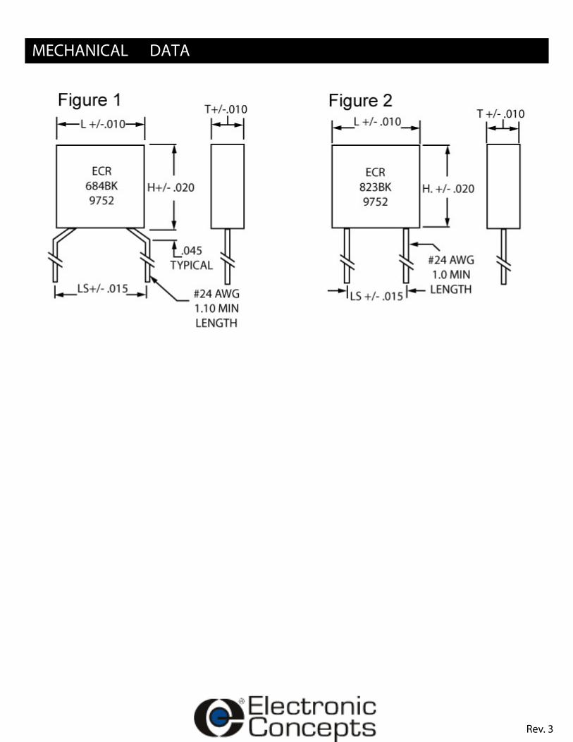
DATA
EC PARTNUMBER CAP µF VDC
PHYSICAL SIZE LEADSPACING
LS
FIGURENO.T H L
ECR102G_ 0.0010 250 0.090 0.190 0.190 0.2 1ECR122G_ 0.0012 250 0.090 0.190 0.190 0.2 1ECR152G_ 0.0015 250 0.090 0.190 0.190 0.2 1ECR182G_ 0.0018 250 0.090 0.190 0.190 0.2 1ECR222G_ 0.0022 250 0.090 0.190 0.190 0.2 1ECR272G_ 0.0027 250 0.090 0.190 0.190 0.2 1ECR332G_ 0.0033 250 0.090 0.190 0.190 0.2 1ECR392F_ 0.0039 200 0.090 0.190 0.190 0.2 1ECR472F_ 0.0047 200 0.090 0.190 0.190 0.2 1ECR562F_ 0.0056 200 0.090 0.190 0.190 0.2 1ECR682E_ 0.0068 150 0.090 0.190 0.190 0.2 1ECR822E_ 0.0082 150 0.090 0.190 0.190 0.2 1ECR103D_ 0.0100 100 0.090 0.190 0.190 0.2 1ECR123D_ 0.0120 100 0.090 0.190 0.190 0.2 1ECR153D_ 0.0150 100 0.090 0.190 0.190 0.2 1ECR183D_ 0.0180 100 0.090 0.190 0.190 0.2 1ECR223C_ 0.0220 75 0.090 0.190 0.190 0.2 1ECR273C_ 0.0270 75 0.090 0.190 0.190 0.2 1ECR333B_ 0.0330 50 0.090 0.190 0.190 0.2 1ECR393B_ 0.0390 50 0.090 0.190 0.190 0.2 1ECR473B_ 0.0470 50 0.090 0.190 0.190 0.2 1ECR563B_ 0.0560 50 0.090 0.190 0.190 0.2 1ECR683B_ 0.0680 50 0.095 0.245 0.295 0.2 2ECR823B_ 0.0820 50 0.095 0.245 0.295 0.2 2ECR104B_ 0.1000 50 0.095 0.245 0.295 0.2 2ECR124B_ 0.1200 50 0.095 0.295 0.295 0.2 2ECR154B_ 0.1500 50 0.095 0.295 0.295 0.2 2ECR184B_ 0.1800 50 0.095 0.295 0.295 0.2 2ECR224B_ 0.2200 50 0.095 0.395 0.395 0.3 2ECR274B_ 0.2700 50 0.095 0.395 0.395 0.3 2ECR334B_ 0.3300 50 0.095 0.395 0.395 0.3 2ECR394B_ 0.3900 50 0.095 0.395 0.395 0.3 2ECR474B_ 0.4700 50 0.145 0.395 0.395 0.3 2ECR564B_ 0.5600 50 0.145 0.395 0.395 0.3 2ECR684B_ 0.6800 50 0.195 0.395 0.395 0.3 2ECR824B_ 0.8200 50 0.195 0.395 0.395 0.3 2ECR105B_ 1.0000 50 0.195 0.395 0.395 0.3 2
Rev. 3
DATA
Rev. 3

INFORMATION
comparable to a ceramic CK05 capacitor. Besides the superior electrical characteristics these capacitors are self-healing,
inherent in ceramic capacitors.
TO ORDER
TYPEECR-Radial Leads ECRSTYLE / VOLTAGEB=50VDC, C=75VDC, D=100VDC, E=150VDC, F=200VDC, G=250VDC BCAPACITANCE IN PICOFARADSThe two digits are the third digit represents thenumber of zero to follow to express the capacitance in picofarads.
104
TOLERANCEF=±1%, G=±2%, J=±5%, K=±10%, M=±20% K
Marking And Date CodeAll capacitors are marked with company initials "EC", corporate logo or EC trademark—in addition to type ECR, capacitance,tolerance, rated DC working voltage and date code. The two digits of the date code represent the year, the second two digits theweek, i.e., 0952 is the 52nd week of 2009, 0902 is the second week of 2009.
Quality AssuranceMajor emphasis is placed on quality assurance. EC is an ISO 9001-2000 and AS9100:2004 Company. Raw materialinspection and the use of SPC manufacturing procedures assure the highest quality standards. Procedures are fully described in theEC Quality Control Manual. Electronic Concepts will continue to advance the state-of-the-art by utilizing leading edge technology,compact capacitor designs and establishing reliability procedures.
United States EuropeEastern:*Headquarters*P.O. Box 1278Eatontown,NJ 07724Tel: 732-542-7880Fax: 732-542-0524
Central:Illinois 630-668-8747
email: [email protected]:www.ecicaps.com
IrelandElectronic ConceptsEurope LTDIDA Estate, OughteradCo. Galway, Irelandtel: +353-91-552385,552432fax: +353-91-552387email: [email protected]:www.electronicconcepts.ie
Rev. 3