AVIM 105A and 106A Combustion Heater Operation and Maintenance
13
JANITROL / SOUTHWIND COMBUSTION HEATER OPERATION AND MAINTENANCE OBJECTIVE: Identify components, explain theory of operation, inspect and troubleshoot combustion heaters. SEE ALSO: www.haroldhaskinsinc.com EQUIPMENT: Stand mounted Janitrol heater and various combustion heater components.
description
AVIM 105A and 106A Combustion Heater Operation and Maintenance
Transcript of AVIM 105A and 106A Combustion Heater Operation and Maintenance
JANITROL / SOUTHWIND COMBUSTION HEATER OPERATION AND MAINTENANCE
OBJECTIVE: Identify components, explain theory of operation, inspect and troubleshoot combustion heaters. SEE ALSO: www.haroldhaskinsinc.com EQUIPMENT: Stand mounted Janitrol heater and various combustion heater components.
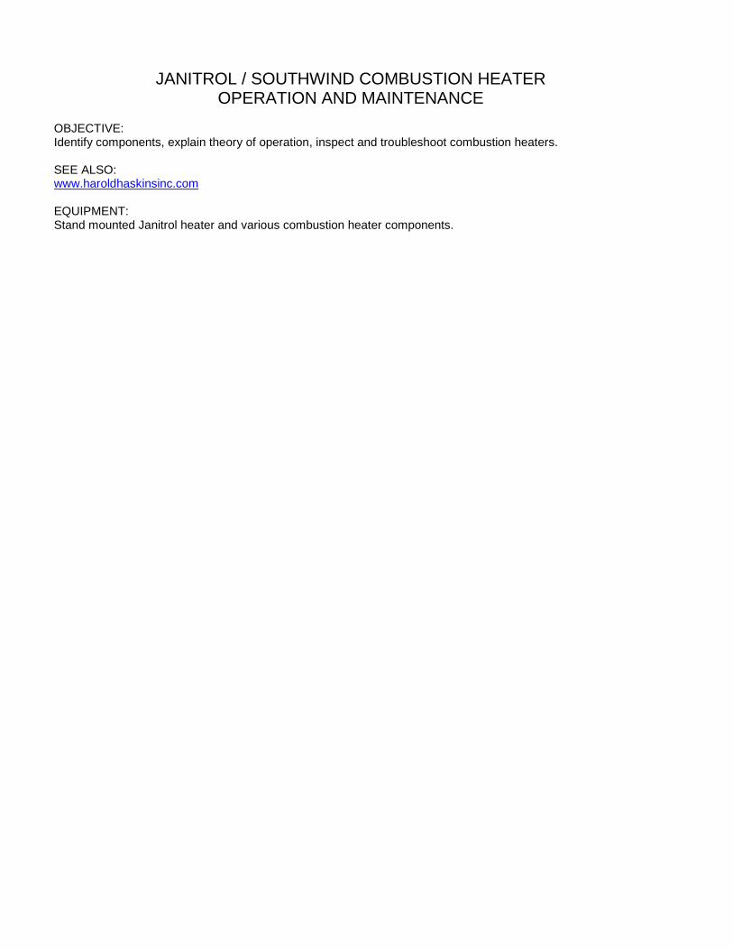
COMBUSTION HEATERS
Janitrol (JanAero) heaters, used in airplanes and helicopters, range in capacity from 15,000 to 50,000 BTU’s per hour. Common model numbers are B-2500, B-3500 and B-4500. Models are further broken down into 12 and 24 volt DC units which burn either gasoline or turbine fuel. Fuel consumption varies by model, somewhere between 0.208 and 0.309 gallons/hr. of operation. Fuel pressure requirements are approximately 7 PSI. The design of all heater models is similar. The diameter of many of the models is the same. Higher BTU output is achieved by increasing the length of each unit.
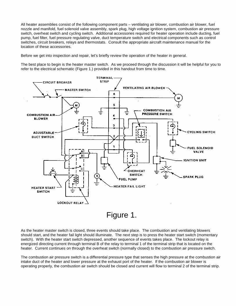
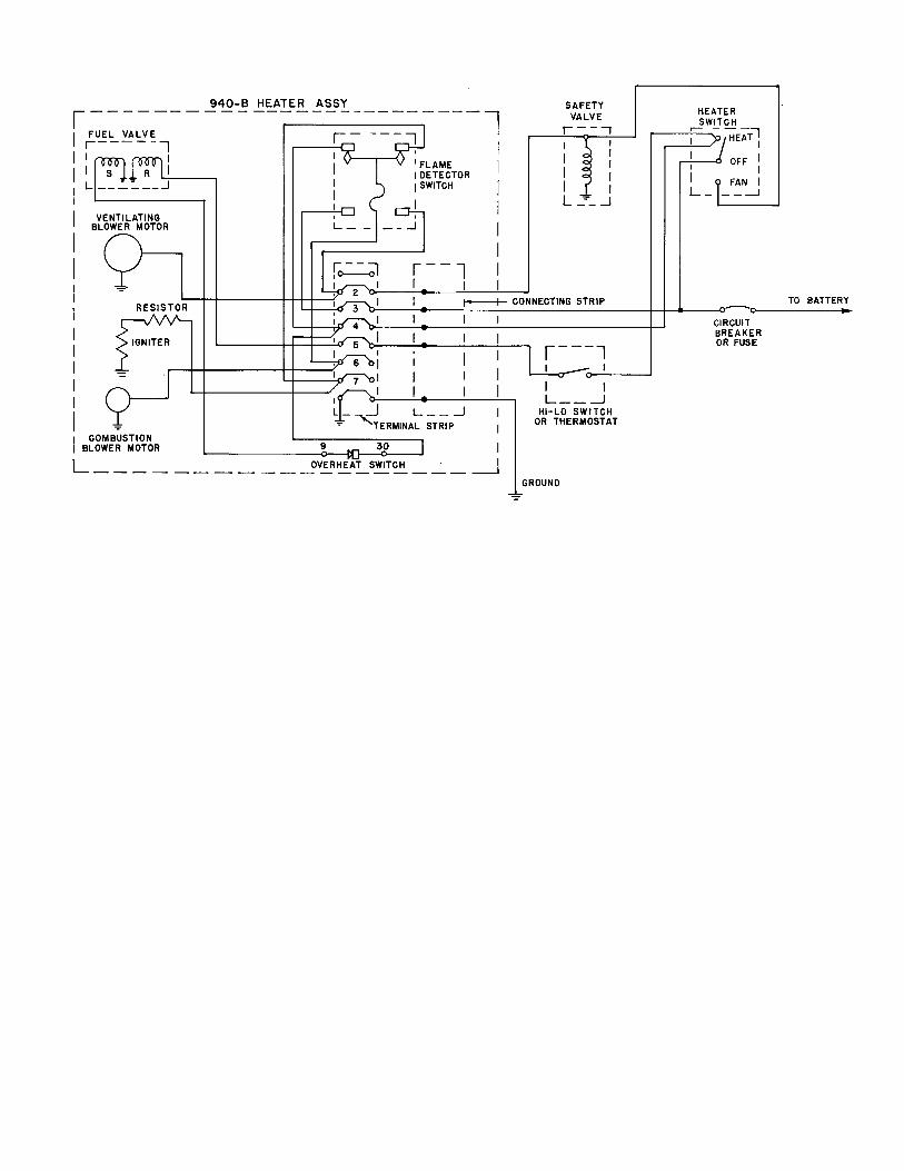
All heater assemblies consist of the following component parts – ventilating air blower, combustion air blower, fuel nozzle and manifold, fuel solenoid valve assembly, spark plug, high voltage ignition system, combustion air pressure switch, overheat switch and cycling switch. Additional accessories required for heater operation include ducting, fuel pump, fuel filter, fuel pressure regulating valve, duct temperature switch and electrical components such as control switches, circuit breakers, relays and thermostats. Consult the appropriate aircraft maintenance manual for the location of these accessories. Before we get into inspection and repair, let’s briefly review the operation of the heater in general. The best place to begin is the heater master switch. As we proceed through the discussion it will be helpful for you to refer to the electrical schematic (Figure 1.) provided in this handout from time to time.
Figure 1. As the heater master switch is closed, three events should take place. The combustion and ventilating blowers should start, and the heater fail light should illuminate. The next step is to press the heater start switch (momentary switch). With the heater start switch depressed, another sequence of events takes place. The lockout relay is energized directing current through terminal B of the relay to terminal 1 of the terminal strip that is located on the heater. Current continues on through the overheat switch (normally closed) to the combustion air pressure switch. The combustion air pressure switch is a differential pressure type that senses the high pressure at the combustion air intake duct of the heater and lower pressure at the exhaust port of the heater. If the combustion air blower is operating properly, the combustion air switch should be closed and current will flow to terminal 2 of the terminal strip.
From terminal 2, current is provided to the ignition system, the fuel pump, back to the lockout relay holding it energized, and to the adjustable duct switch (thermostat). The adjustable duct switch, which is operated from the cockpit, is the primary temperature control for the heater. If more heat is required, the adjustable duct switch will be closed and current will flow through the cycling switch (normally closed) to the fuel solenoid valve. The heater should now light off, the heater fail light will extinguish, and the (momentary) heater start switch can be released. During normal operation, the heater will cycle through the adjustable duct switch. Once the preset temperature is reached, the duct switch will open, removing voltage from the fuel solenoid valve. The fuel solenoid valve, which is spring loaded closed, will stop the flow of fuel and in effect stop combustion in the heater (cycle the heater off). The remaining heater components, including the ignition system, fuel pump and blower motors will continue to operate. In the event the heater duct switch should fail to cycle the heater off at the preset temperature, the cycling switch automatically assumes control of the heater. The cycling switch, which is mounted directly on the heater, will remove current from the fuel solenoid valve at approximately 2100 F. and reapply voltage to the fuel solenoid valve at 2000 F. The cycling switch, which is in series with the duct switch, will permit continued heater operation. However, the temperature will not be adjustable from the cockpit. If the adjustable duct switch (thermostat) and cycling switch should both fail in the closed (ON) position, the overheat switch will open and shut down the heater completely. An open overheat switch which occurs between 3000 F. and 4000 F. will remove voltage from the lockout relay, which in turn will remove voltage from the ignition unit, fuel pump, fuel solenoid valve, and also cause the heater fail light to illuminate. The ventilating and combustion air blowers will continue to operate in an attempt to both cool the heater and purge the combustion chamber. Failure of the combustion air blower will also shut down the heater in a like fashion by opening the combustion air pressure switch. Once you understand how the heater operates, troubleshooting becomes much easier. You can systematically proceed from the master switch through the control system to find the malfunctioning component. Some heater installations include additional safety devices such as a separate “wing-mounted” fuel solenoid valve that is only powered when the heater master switch is closed (on) and possibly a damper-type combustion air fire valve. Additionally, some heater installations differ in that the combustion air blower motor drives a mechanical fuel pump by a common shaft. A separate hour meter may also be used to record actual time of heater operation. The two greatest dangers resulting from faulty combustion heater operation are carbon monoxide poisoning (leaky combustion chamber) or a fuel fire (leaky fuel lines and fittings). Your attention to detail during inspection will help to prevent these dangers from occurring. Janitrol combustion heater inspection can generally be placed into three categories: preflight, 100-hour and 500-hour. Also, most Janitrol combustion heaters are subject to FAA Airworthiness Directives that require periodic inspection that includes a combustion chamber pressure decay test. Stewart-Warner (South Wind) heaters are subject to a similar FAA Airworthiness Directive. Janitrol heaters failing the inspection and pressure decay test must be overhauled (referred to as a Major Overhaul by Janitrol). See the appropriate Janitrol Overhaul Manual for overhaul requirements. Additionally FAA Airworthiness Directives requires visual inspection and pressure testing of certain combustion heater fuel regulator shut-off valves for leaks. Some Piper aircraft are also subject to an FAA Airworthiness Directives if equipped with certain Stewart-Warner combustion heaters or heater fuel pumps. A preflight inspection usually consists of a visual inspection of the ventilating and combustion air inlets, exhaust outlet and the fuel drain for obstructions or damage. Maintenance personnel should also accomplish an operational check at least once a week. During the operational check, make sure the heater is cycling through the adjustable duct switch (thermostat) and that no fumes or carbon monoxide (CO) is being emitted into the cockpit or cabin. After heater shutdown, run the blowers for several minutes to cool down and purge the combustion chamber. A 100-hour inspection includes all the preflight items. In addition, inspect all fuel lines for and components for security of attachment and electrical wiring for chaffing and loose connections. Remove the igniter plug and check its condition. Inspect the high voltage lead to the spark plug for condition and evidence of arcing. Inspect the attach points of the combustion air blower for condition and security and also check the blower itself for security and condition. It is a good idea to inspect the brushes in both blower motors each 100-hours of heater operation.
The 500-hour inspection requires a pressure decay test of the combustion chamber. It is generally not necessary to remove the heater from the aircraft for this inspection. Should the combustion chamber show leakage as a result of the pressure decay test, the heater must be removed from service and overhauled (as mandated by an Airworthiness Directive). Consult the aircraft maintenance manual for information regarding removal of the heater from the aircraft. Once the heater has been removed from the aircraft, you will also need the appropriate heater overhaul manual to perform the 500-hour overhaul. The following information highlights the overhaul process. Refer to the overhaul manual for complete overhaul instructions. Usually the cycling switch, combustion air intake duct and the wiring harness are removed to facilitate removal of the heater from the aircraft. The combustion tube (if found serviceable) is removed from the heater and cleaned of carbon. One method that may be used is to place a quantity of BB’s into the combustion tube, plug the openings, and then shake the assembly for several minutes. This method is quite effective. After you remove the BB’s and loose carbon, blow out the remaining residue with compressed air. This job is best done outside. Be sure not to stand downwind! The fuel nozzle is also frequently covered with carbon. Using a 5/8-inch socket, carefully remove the nozzle from the manifold. Clean the fuel nozzle exterior with MEK and a soft brush. Be especially cautious when cleaning the face of the nozzle. The orifice opening can be easily damaged and will result in an improper spray pattern and rejection of the nozzle assembly. Normally, the spray nozzle does not require disassembly for internal cleaning. However, if the spray pattern is incorrect during the flow check, you can disassemble the nozzle and clean it. This may solve the problem. The fuel solenoid valve should be disassembled and the O-ring replaced. After reassembly, the fuel solenoid valve and spray nozzle should be flow checked. Make sure that the solenoid valve is working properly. When voltage is removed from the solenoid coil, fuel flow should stop within two seconds. This will ensure that the fuel solenoid valve cycles the heater off in normal operation. Observe the fuel spray pattern during the flow check of the fuel solenoid valve and spray nozzle. Disassemble the combustion tube assembly and inspect the combustion head and tube for cracks. Commonly, cracks form in the radius of the combustion head, around the circumference of the heater tube, or in the crossover tube. A pressure decay test prior to disassembly may have also confirmed the presence of cracks in the combustion tube assembly. Both blower motors/fans are checked for speed using a strobe light. The operational blower speeds are typically listed in the overhaul manual and on the blower data plate. Inspect the fuel pump motor armature, brushes and bearings for condition, the fuel shut-off valve for proper operation and the fuel pressure regulator for correct operating pressure. The fuel filter should also be inspected for cleanliness. Overhauled heaters are given an operational test run to certify the heater as airworthy. Janitrol provides a description of the heater operational test set-up in their overhaul manual. During the operational test, the heater is placed in a test stand and a thermometer located in the test duct monitors temperatures. Air pressure is also checked by two manometers.
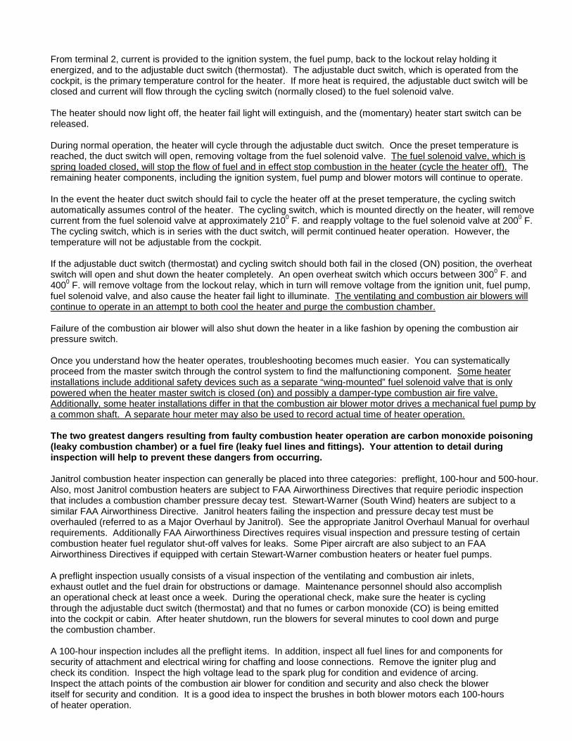
TROUBLESHOOTING The operation of a combustion heater requires air, fuel and electricity. Assuming that these three things are available to the heater, we can begin to look at some of the problems that could result in heater failure. A typical combustion heater is illustrated in Figure 2. Figure 2 does not represent any specific heater, but most combustion heaters are similar.
Figure 2.
It is important that you have a copy of the electrical schematic for the specific heater you are working with and know the location of the heater component parts before using this troubleshooting aid. The troubleshooting chart, along with the heater schematic will serve as a guide in determining what is wrong with the heater. You will need a DC voltmeter and physical access to the heater to perform these checks. There are several things you should be aware of before you start. An optional overheat fuse is installed as a “fail-safe” device in some heater assemblies. It is normally installed in a location that is not accessible in flight. When the fuse has blown, the heater will not operate, but the combustion and ventilating air blowers will operate. Anytime you find this fuse blown, it will indicate that a serious malfunction of the heater has occurred.
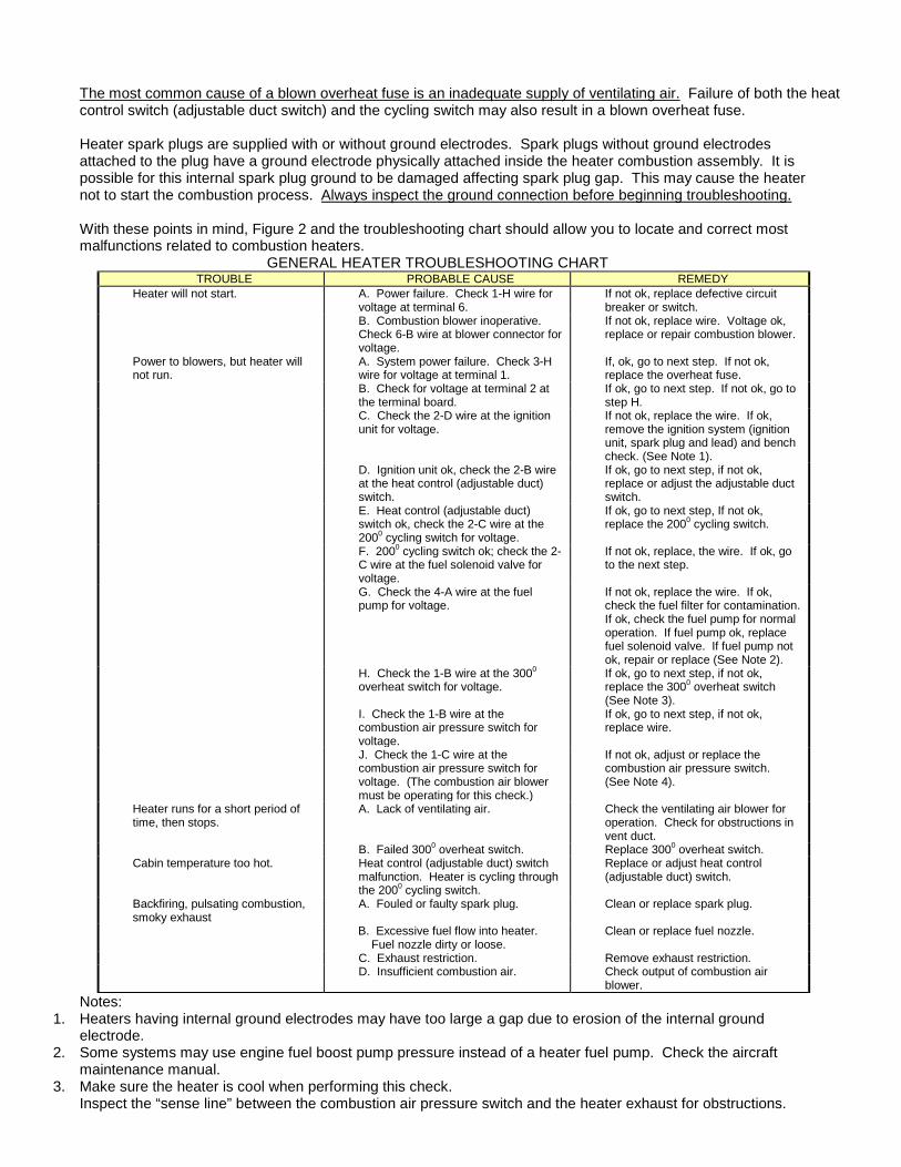
The most common cause of a blown overheat fuse is an inadequate supply of ventilating air. Failure of both the heat control switch (adjustable duct switch) and the cycling switch may also result in a blown overheat fuse. Heater spark plugs are supplied with or without ground electrodes. Spark plugs without ground electrodes attached to the plug have a ground electrode physically attached inside the heater combustion assembly. It is possible for this internal spark plug ground to be damaged affecting spark plug gap. This may cause the heater not to start the combustion process. Always inspect the ground connection before beginning troubleshooting. With these points in mind, Figure 2 and the troubleshooting chart should allow you to locate and correct most malfunctions related to combustion heaters.
GENERAL HEATER TROUBLESHOOTING CHART TROUBLE PROBABLE CAUSE REMEDY
Heater will not start. A. Power failure. Check 1-H wire for voltage at terminal 6.
If not ok, replace defective circuit breaker or switch.
B. Combustion blower inoperative. Check 6-B wire at blower connector for voltage.
If not ok, replace wire. Voltage ok, replace or repair combustion blower.
Power to blowers, but heater will not run.
A. System power failure. Check 3-H wire for voltage at terminal 1.
If, ok, go to next step. If not ok, replace the overheat fuse.
B. Check for voltage at terminal 2 at the terminal board.
If ok, go to next step. If not ok, go to step H.
C. Check the 2-D wire at the ignition unit for voltage.
If not ok, replace the wire. If ok, remove the ignition system (ignition unit, spark plug and lead) and bench check. (See Note 1).
D. Ignition unit ok, check the 2-B wire at the heat control (adjustable duct) switch.
If ok, go to next step, if not ok, replace or adjust the adjustable duct switch.
E. Heat control (adjustable duct) switch ok, check the 2-C wire at the 2000 cycling switch for voltage.
If ok, go to next step, If not ok, replace the 2000 cycling switch.
F. 2000 cycling switch ok; check the 2-C wire at the fuel solenoid valve for voltage.
If not ok, replace, the wire. If ok, go to the next step.
G. Check the 4-A wire at the fuel pump for voltage.
If not ok, replace the wire. If ok, check the fuel filter for contamination. If ok, check the fuel pump for normal operation. If fuel pump ok, replace fuel solenoid valve. If fuel pump not ok, repair or replace (See Note 2).
H. Check the 1-B wire at the 3000 overheat switch for voltage.
If ok, go to next step, if not ok, replace the 3000 overheat switch (See Note 3).
I. Check the 1-B wire at the combustion air pressure switch for voltage.
If ok, go to next step, if not ok, replace wire.
J. Check the 1-C wire at the combustion air pressure switch for voltage. (The combustion air blower must be operating for this check.)
If not ok, adjust or replace the combustion air pressure switch. (See Note 4).
Heater runs for a short period of time, then stops.
A. Lack of ventilating air. Check the ventilating air blower for operation. Check for obstructions in vent duct.
B. Failed 3000 overheat switch. Replace 3000 overheat switch. Cabin temperature too hot. Heat control (adjustable duct) switch
malfunction. Heater is cycling through the 2000 cycling switch.
Replace or adjust heat control (adjustable duct) switch.
Backfiring, pulsating combustion, smoky exhaust
A. Fouled or faulty spark plug. Clean or replace spark plug.
B. Excessive fuel flow into heater. Fuel nozzle dirty or loose.
Clean or replace fuel nozzle.
C. Exhaust restriction. Remove exhaust restriction. D. Insufficient combustion air. Check output of combustion air
blower. Notes:
1. Heaters having internal ground electrodes may have too large a gap due to erosion of the internal ground electrode.
2. Some systems may use engine fuel boost pump pressure instead of a heater fuel pump. Check the aircraft maintenance manual.
3. Make sure the heater is cool when performing this check. Inspect the “sense line” between the combustion air pressure switch and the heater exhaust for obstructions.
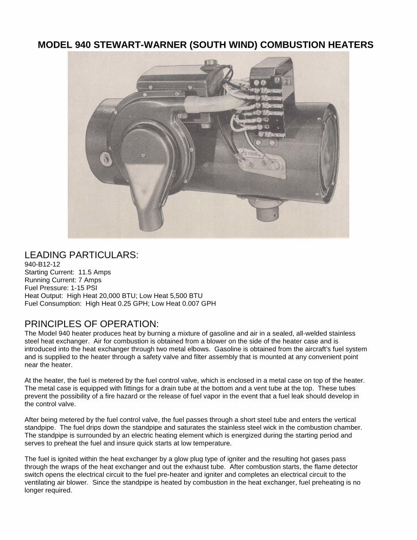
MODEL 940 STEWART-WARNER (SOUTH WIND) COMBUSTION HEATERS LEADING PARTICULARS: 940-B12-12 Starting Current: 11.5 Amps Running Current: 7 Amps Fuel Pressure: 1-15 PSI Heat Output: High Heat 20,000 BTU; Low Heat 5,500 BTU Fuel Consumption: High Heat 0.25 GPH; Low Heat 0.007 GPH PRINCIPLES OF OPERATION: The Model 940 heater produces heat by burning a mixture of gasoline and air in a sealed, all-welded stainless steel heat exchanger. Air for combustion is obtained from a blower on the side of the heater case and is introduced into the heat exchanger through two metal elbows. Gasoline is obtained from the aircraft’s fuel system and is supplied to the heater through a safety valve and filter assembly that is mounted at any convenient point near the heater. At the heater, the fuel is metered by the fuel control valve, which is enclosed in a metal case on top of the heater. The metal case is equipped with fittings for a drain tube at the bottom and a vent tube at the top. These tubes prevent the possibility of a fire hazard or the release of fuel vapor in the event that a fuel leak should develop in the control valve. After being metered by the fuel control valve, the fuel passes through a short steel tube and enters the vertical standpipe. The fuel drips down the standpipe and saturates the stainless steel wick in the combustion chamber. The standpipe is surrounded by an electric heating element which is energized during the starting period and serves to preheat the fuel and insure quick starts at low temperature. The fuel is ignited within the heat exchanger by a glow plug type of igniter and the resulting hot gases pass through the wraps of the heat exchanger and out the exhaust tube. After combustion starts, the flame detector switch opens the electrical circuit to the fuel pre-heater and igniter and completes an electrical circuit to the ventilating air blower. Since the standpipe is heated by combustion in the heat exchanger, fuel preheating is no longer required.
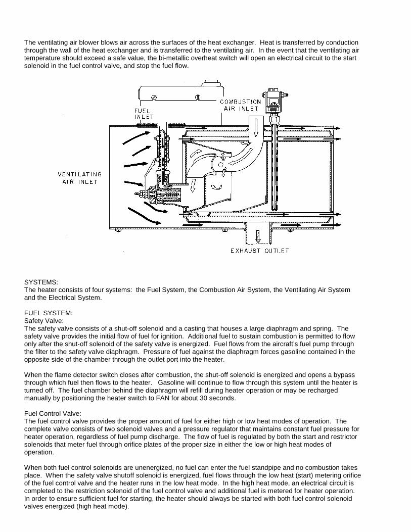
The ventilating air blower blows air across the surfaces of the heat exchanger. Heat is transferred by conduction through the wall of the heat exchanger and is transferred to the ventilating air. In the event that the ventilating air temperature should exceed a safe value, the bi-metallic overheat switch will open an electrical circuit to the start solenoid in the fuel control valve, and stop the fuel flow. SYSTEMS: The heater consists of four systems: the Fuel System, the Combustion Air System, the Ventilating Air System and the Electrical System. FUEL SYSTEM: Safety Valve: The safety valve consists of a shut-off solenoid and a casting that houses a large diaphragm and spring. The safety valve provides the initial flow of fuel for ignition. Additional fuel to sustain combustion is permitted to flow only after the shut-off solenoid of the safety valve is energized. Fuel flows from the aircraft’s fuel pump through the filter to the safety valve diaphragm. Pressure of fuel against the diaphragm forces gasoline contained in the opposite side of the chamber through the outlet port into the heater. When the flame detector switch closes after combustion, the shut-off solenoid is energized and opens a bypass through which fuel then flows to the heater. Gasoline will continue to flow through this system until the heater is turned off. The fuel chamber behind the diaphragm will refill during heater operation or may be recharged manually by positioning the heater switch to FAN for about 30 seconds. Fuel Control Valve: The fuel control valve provides the proper amount of fuel for either high or low heat modes of operation. The complete valve consists of two solenoid valves and a pressure regulator that maintains constant fuel pressure for heater operation, regardless of fuel pump discharge. The flow of fuel is regulated by both the start and restrictor solenoids that meter fuel through orifice plates of the proper size in either the low or high heat modes of operation. When both fuel control solenoids are unenergized, no fuel can enter the fuel standpipe and no combustion takes place. When the safety valve shutoff solenoid is energized, fuel flows through the low heat (start) metering orifice of the fuel control valve and the heater runs in the low heat mode. In the high heat mode, an electrical circuit is completed to the restriction solenoid of the fuel control valve and additional fuel is metered for heater operation. In order to ensure sufficient fuel for starting, the heater should always be started with both fuel control solenoid valves energized (high heat mode).
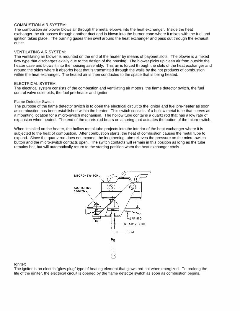
COMBUSTION AIR SYSTEM: The combustion air blower blows air through the metal elbows into the heat exchanger. Inside the heat exchanger the air passes through another duct and is blown into the burner cone where it mixes with the fuel and ignition takes place. The burning gases then swirl around the heat exchanger and pass out through the exhaust outlet. VENTILATING AIR SYSTEM: The ventilating air blower is mounted on the end of the heater by means of bayonet slots. The blower is a mixed flow type that discharges axially due to the design of the housing. The blower picks up clean air from outside the heater case and blows it into the housing assembly. This air is forced through the slots of the heat exchanger and around the sides where it absorbs heat that is transmitted through the walls by the hot products of combustion within the heat exchanger. The heated air is then conducted to the space that is being heated. ELECTRICAL SYSTEM: The electrical system consists of the combustion and ventilating air motors, the flame detector switch, the fuel control valve solenoids, the fuel pre-heater and igniter. Flame Detector Switch: The purpose of the flame detector switch is to open the electrical circuit to the igniter and fuel pre-heater as soon as combustion has been established within the heater. This switch consists of a hollow metal tube that serves as a mounting location for a micro-switch mechanism. The hollow tube contains a quartz rod that has a low rate of expansion when heated. The end of the quarts rod bears on a spring that actuates the button of the micro-switch. When installed on the heater, the hollow metal tube projects into the interior of the heat exchanger where it is subjected to the heat of combustion. After combustion starts, the heat of combustion causes the metal tube to expand. Since the quartz rod does not expand, the lengthening tube relieves the pressure on the micro-switch button and the micro-switch contacts open. The switch contacts will remain in this position as long as the tube remains hot, but will automatically return to the starting position when the heat exchanger cools.
Igniter: The igniter is an electric “glow plug” type of heating element that glows red hot when energized. To prolong the life of the igniter, the electrical circuit is opened by the flame detector switch as soon as combustion begins.
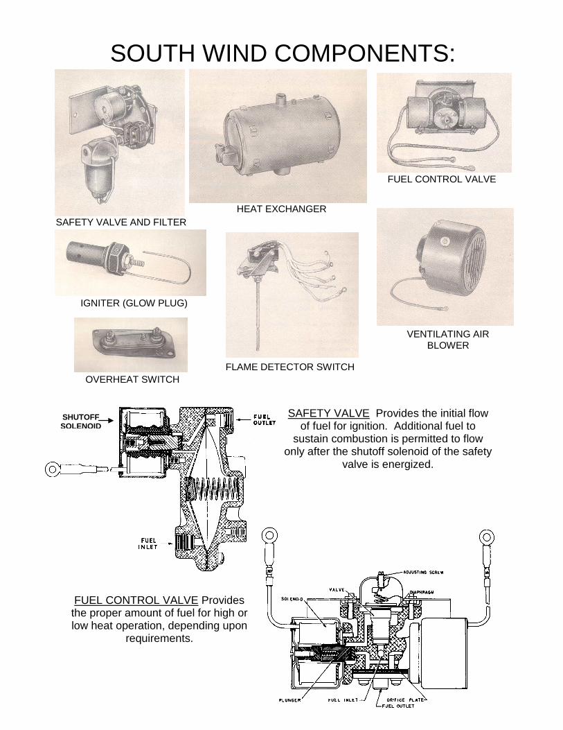
SAFETY VALVE AND FILTER
SOUTH WIND COMPONENTS:
HEAT EXCHANGER
FUEL CONTROL VALVE
IGNITER (GLOW PLUG)
FLAME DETECTOR SWITCH
VENTILATING AIR BLOWER
OVERHEAT SWITCH
SHUTOFF SOLENOID
FUEL CONTROL VALVE Provides the proper amount of fuel for high or low heat operation, depending upon
requirements.
SAFETY VALVE Provides the initial flow of fuel for ignition. Additional fuel to
sustain combustion is permitted to flow only after the shutoff solenoid of the safety
valve is energized.
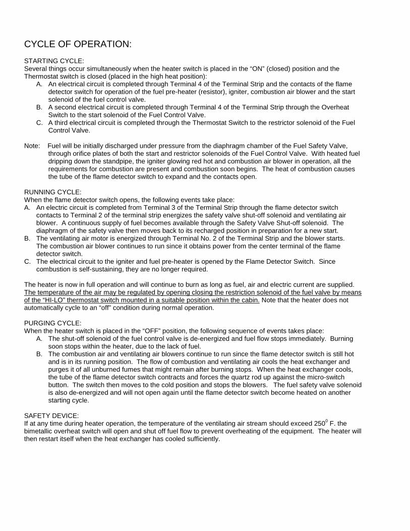
CYCLE OF OPERATION: STARTING CYCLE: Several things occur simultaneously when the heater switch is placed in the “ON” (closed) position and the Thermostat switch is closed (placed in the high heat position):
A. An electrical circuit is completed through Terminal 4 of the Terminal Strip and the contacts of the flame detector switch for operation of the fuel pre-heater (resistor), igniter, combustion air blower and the start solenoid of the fuel control valve.
B. A second electrical circuit is completed through Terminal 4 of the Terminal Strip through the Overheat Switch to the start solenoid of the Fuel Control Valve.
C. A third electrical circuit is completed through the Thermostat Switch to the restrictor solenoid of the Fuel Control Valve.
Note: Fuel will be initially discharged under pressure from the diaphragm chamber of the Fuel Safety Valve,
through orifice plates of both the start and restrictor solenoids of the Fuel Control Valve. With heated fuel dripping down the standpipe, the igniter glowing red hot and combustion air blower in operation, all the requirements for combustion are present and combustion soon begins. The heat of combustion causes the tube of the flame detector switch to expand and the contacts open.
RUNNING CYCLE: When the flame detector switch opens, the following events take place: A. An electric circuit is completed from Terminal 3 of the Terminal Strip through the flame detector switch
contacts to Terminal 2 of the terminal strip energizes the safety valve shut-off solenoid and ventilating air blower. A continuous supply of fuel becomes available through the Safety Valve Shut-off solenoid. The diaphragm of the safety valve then moves back to its recharged position in preparation for a new start.
B. The ventilating air motor is energized through Terminal No. 2 of the Terminal Strip and the blower starts. The combustion air blower continues to run since it obtains power from the center terminal of the flame detector switch.
C. The electrical circuit to the igniter and fuel pre-heater is opened by the Flame Detector Switch. Since combustion is self-sustaining, they are no longer required.
The heater is now in full operation and will continue to burn as long as fuel, air and electric current are supplied. The temperature of the air may be regulated by opening closing the restriction solenoid of the fuel valve by means of the “HI-LO” thermostat switch mounted in a suitable position within the cabin. Note that the heater does not automatically cycle to an “off” condition during normal operation. PURGING CYCLE: When the heater switch is placed in the “OFF” position, the following sequence of events takes place:
A. The shut-off solenoid of the fuel control valve is de-energized and fuel flow stops immediately. Burning soon stops within the heater, due to the lack of fuel.
B. The combustion air and ventilating air blowers continue to run since the flame detector switch is still hot and is in its running position. The flow of combustion and ventilating air cools the heat exchanger and purges it of all unburned fumes that might remain after burning stops. When the heat exchanger cools, the tube of the flame detector switch contracts and forces the quartz rod up against the micro-switch button. The switch then moves to the cold position and stops the blowers. The fuel safety valve solenoid is also de-energized and will not open again until the flame detector switch become heated on another starting cycle.
SAFETY DEVICE: If at any time during heater operation, the temperature of the ventilating air stream should exceed 2500 F. the bimetallic overheat switch will open and shut off fuel flow to prevent overheating of the equipment. The heater will then restart itself when the heat exchanger has cooled sufficiently.