Avigilon Workflow Guide.book
119
Access Control Manager Application Configuration and Work Flow Guide
Transcript of Avigilon Workflow Guide.book

Access Control Manager
Application Configuration and Work Flow Guide

Access Control Manager
Version 5.0/AV01-1213
Version 5.0Copyright© 2012-2013 Avigilon Inc.
Avigilon Inc.Box 378#101-1001 West BroadwayVancouver, British ColumbiaV6H 4E4Canada
Phone:888.281.5182 Web:www.avigilon.com
ii
Access Control Manager
Getting HelpIf you encounter a problem that is not discussed in available Avigilon Access Control Manager user guides or online help files, and need technical support, please contact your local Value Added Reseller (VAR) or Avigilon support (888.281.5182).
When contacting your VAR, please be sure to have your registration material, serial number, and software version number available.
For future reference, record these numbers here.
Serial Number: _________________________________
Version Number: ________________________________
VAR: __________________________________________
VAR Phone #: __________________________________
iii
1
Table of Contents
Overview . . . . . . . . . . . . . . . . . . . . . . . . . . . . . . . . . . . . . . . . . . . . . . . 1Flowchart . . . . . . . . . . . . . . . . . . . . . . . . . . . . . . . . . . . . . . . . . . . . . . . . . . . . . . 2
Access Control Manager Workflow. . . . . . . . . . . . . . . . . . . . . . . . . 3Connecting and Accessing the Access Control Manager
Appliance . . . . . . . . . . . . . . . . . . . . . . . . . . . . . . . . . . . . . . . . . . . . . . . . . . . . . 3Required Items . . . . . . . . . . . . . . . . . . . . . . . . . . . . . . . . . . . . . . . . . 3Configuration Procedure . . . . . . . . . . . . . . . . . . . . . . . . . . . . . . . . . 3
Panels . . . . . . . . . . . . . . . . . . . . . . . . . . . . . . . . . . . . . . . . . . . . . . . . . . . . . . . . . 13Panel Add Summary . . . . . . . . . . . . . . . . . . . . . . . . . . . . . . . . . . . . . 17
Areas . . . . . . . . . . . . . . . . . . . . . . . . . . . . . . . . . . . . . . . . . . . . . . . . . . . . . . . . . .19Doors . . . . . . . . . . . . . . . . . . . . . . . . . . . . . . . . . . . . . . . . . . . . . . . . . . . . . . . . . .21Schedules . . . . . . . . . . . . . . . . . . . . . . . . . . . . . . . . . . . . . . . . . . . . . . . . . . . . . 33Holidays . . . . . . . . . . . . . . . . . . . . . . . . . . . . . . . . . . . . . . . . . . . . . . . . . . . . . . 35Card Formats . . . . . . . . . . . . . . . . . . . . . . . . . . . . . . . . . . . . . . . . . . . . . . . . . . .41Event Types . . . . . . . . . . . . . . . . . . . . . . . . . . . . . . . . . . . . . . . . . . . . . . . . . . . 44Events . . . . . . . . . . . . . . . . . . . . . . . . . . . . . . . . . . . . . . . . . . . . . . . . . . . . . . . . 46Roles . . . . . . . . . . . . . . . . . . . . . . . . . . . . . . . . . . . . . . . . . . . . . . . . . . . . . . . . . 49Access Groups . . . . . . . . . . . . . . . . . . . . . . . . . . . . . . . . . . . . . . . . . . . . . . . . . .51Delegation Groups . . . . . . . . . . . . . . . . . . . . . . . . . . . . . . . . . . . . . . . . . . . . . 53Partitions . . . . . . . . . . . . . . . . . . . . . . . . . . . . . . . . . . . . . . . . . . . . . . . . . . . . . . 55
Changing a Background . . . . . . . . . . . . . . . . . . . . . . . . . . . . . . . . 59Adding Pictures . . . . . . . . . . . . . . . . . . . . . . . . . . . . . . . . . . . . . . . . 60Adding Database Fields . . . . . . . . . . . . . . . . . . . . . . . . . . . . . . . . . .61Adding Text . . . . . . . . . . . . . . . . . . . . . . . . . . . . . . . . . . . . . . . . . . . 62Adding Graphics . . . . . . . . . . . . . . . . . . . . . . . . . . . . . . . . . . . . . . . 64Badge Camera Configuration . . . . . . . . . . . . . . . . . . . . . . . . . . . . 65
User-Defined Fields and Lists . . . . . . . . . . . . . . . . . . . . . . . . . . . . . . . . . . . . . 71User-Defined Fields . . . . . . . . . . . . . . . . . . . . . . . . . . . . . . . . . . . . . 71User Lists . . . . . . . . . . . . . . . . . . . . . . . . . . . . . . . . . . . . . . . . . . . . . 72
Routing . . . . . . . . . . . . . . . . . . . . . . . . . . . . . . . . . . . . . . . . . . . . . . . . . . . . . . . 73Collaboration . . . . . . . . . . . . . . . . . . . . . . . . . . . . . . . . . . . . . . . . . . . . . . . . . . 76Identities . . . . . . . . . . . . . . . . . . . . . . . . . . . . . . . . . . . . . . . . . . . . . . . . . . . . . . 77
Adding Identities . . . . . . . . . . . . . . . . . . . . . . . . . . . . . . . . . . . . . . . 77Searching for Identities . . . . . . . . . . . . . . . . . . . . . . . . . . . . . . . . . 86
Identity Profiles . . . . . . . . . . . . . . . . . . . . . . . . . . . . . . . . . . . . . . . . . . . . . . . . 87Adding Identity Profiles . . . . . . . . . . . . . . . . . . . . . . . . . . . . . . . . . 87
Reports . . . . . . . . . . . . . . . . . . . . . . . . . . . . . . . . . . . . . . . . . . . . . . . . . . . . . . . 88Maps . . . . . . . . . . . . . . . . . . . . . . . . . . . . . . . . . . . . . . . . . . . . . . . . . . . . . . . . . .91Global Actions . . . . . . . . . . . . . . . . . . . . . . . . . . . . . . . . . . . . . . . . . . . . . . . . . 94Global Linkages . . . . . . . . . . . . . . . . . . . . . . . . . . . . . . . . . . . . . . . . . . . . . . . . 95Elevator Access Levels . . . . . . . . . . . . . . . . . . . . . . . . . . . . . . . . . . . . . . . . . . 97Appliance Back-Up . . . . . . . . . . . . . . . . . . . . . . . . . . . . . . . . . . . . . . . . . . . . . 99Monitoring . . . . . . . . . . . . . . . . . . . . . . . . . . . . . . . . . . . . . . . . . . . . . . . . . . . . . 101
Monitoring Events . . . . . . . . . . . . . . . . . . . . . . . . . . . . . . . . . . . . . . 101Monitoring Alarms . . . . . . . . . . . . . . . . . . . . . . . . . . . . . . . . . . . . . 103Searching for Events and Alarms . . . . . . . . . . . . . . . . . . . . . . . . 105Verifying Door and Identity Status . . . . . . . . . . . . . . . . . . . . . . . .107Monitoring Hardware Status . . . . . . . . . . . . . . . . . . . . . . . . . . . . 109Monitoring Maps . . . . . . . . . . . . . . . . . . . . . . . . . . . . . . . . . . . . . . . 114
OverviewThank you for your purchase of the Access Control Manager software.
This configuration and workflow guide will walk you through the steps required to connect and configure your new Access Control Manager system.
This is not a comprehensive guide of every feature and field in the system. For that, you can review the Access Control Manager online help files. This guide handles the initial setup of your system through the Access Control Manager appliance and bypasses some of the advanced features and tasks that you may want to use later but don’t really need initially.
To that end, we begin with a flowchart of the steps you should take to get your Access Control Manager system up and running.
We hope you enjoy your user experience with the Access Control Manager.
1

FlowchartThe flowchart below shows the basic steps you should follow to complete the setup process.
page 3
page 93
page 21page 19
page 37 page 35
page 33
page 44page 41
page 53
page 76
page 13
page 49
page 71page 57
page 77 page 88
page 46
page 31
page 96 page 94
page 90
page 55
page 73page 65
page 98page 101
page 87
page 51
page 39
2
1
Access Control Manager WorkflowThe following workflow is divided into sections and subsections representing the steps you will take in configuring the Access Control Manager system.
Connecting and Accessing the Access Control Manager Appliance
Required Items
This is a list of items you will need to configure your new Access Control Manager appliance:
• Access Control Manager Appliance (or Access Control Manager Virtual Appliance DVD with License)
• Power Cable• Crossover Cable (not included)• Static IP address• Domain Name Server that will be responsible for resolving the static IP address to a name.
Configuration Procedure
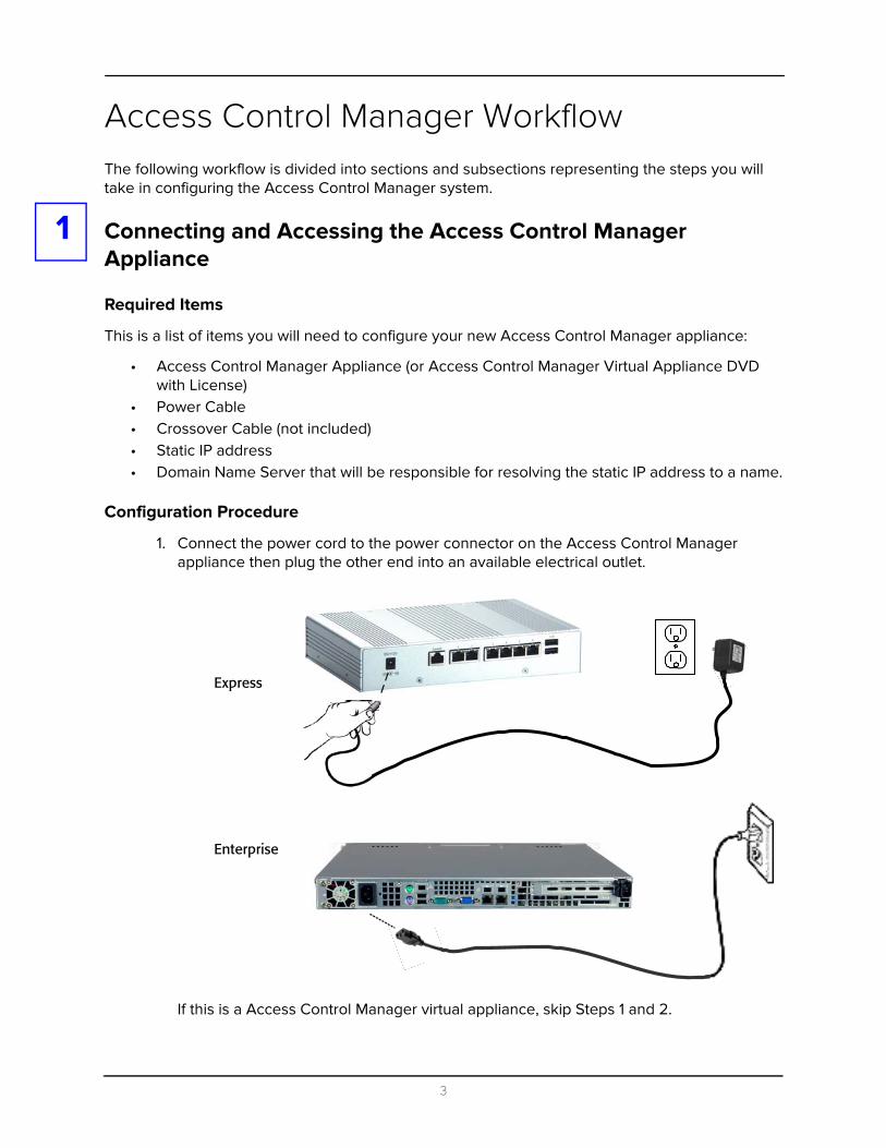
1. Connect the power cord to the power connector on the Access Control Manager appliance then plug the other end into an available electrical outlet.
If this is a Access Control Manager virtual appliance, skip Steps 1 and 2.
Express
Enterprise
3

2. Connect the Access Control Manager appliance to a computer using the crossover cable to Port 2 of the appliance.
3. On your connected computer, open a web browser and type the appropriate address into the address bar.
For the express and enterprise appliance, enter this address:
https://169.254.1.250
For the virtual appliance, enter this address:
https://169.254.1.201
Express
Enterprise
Crossover Cable
(sold separately through third-party retailers)
Connect to Port 2
Crossover Cable
(sold separately through third-party retailers)
Connect to Port 2
4

At this point, you will probably see a message indicating that you are trying to reach an unknown or insecure site, like these examples:
4. Do one of these things:
• If this is Firefox, click the “Or you can add an exception...” or “I understand the risks” link, click the Add Exception button, click Get Certificate, then click Confirm Security Exception button.
• If this is Windows Explorer, click the “Continue to this website (not recommended)” link.
• If this is Safari, click the Continue button.
• If this is Chrome, click the Proceed Anyway button.
This brings you to the login screen like this example:
5. Enter these default values in the corresponding fields:
If this is Internet Explorer:
If this is Safari:
If this is Firefox:
If this is Chrome:
Enter adminin each field
5

Login: adminPassword: admin
NOTE: We highly recommend that you change the login and password for the system administrator account as part of the configuring of your new appliance.
6. Press Sign in.
The home page appears like this example:
7. From the Setup section in the upper right corner, click Settings then System Settings.
8. Make changes as required to the language displayed as well as the token expiration time and the password strength, as required.
9. From the Setup section, click Appliance.
The Appliance page appears like this example:
10. Enter a Name, Host Name, Domain Name, and any other values you need to set.
If you need to change any other fields, they include:
Name Enter a descriptive name for this appliance.
System Name This read-only field designates the name of the entire Access Control Manager system.
6

Host Name This is the DNS name for this appliance and is identified as such under the 'DNS Name' field on the Appliance Listing page.
Domain Name Enter the domain name where this appliance resides.
Name Server Enter the name of the domain server.
Time Server Enter the time server connected to this appliance.
Time zone From the drop-down pick list, specify the time zone where this appliance resides.
Use Daylight Savings Time
Check this box to indicate that this appliance uses Daylight Savings Time, when appropriate.
Enable Remote TCP/IP Management
Check this box to indicate that this appliance can use remote TCP/IP management. By default this feature is checked and enabled, since the configuration or operator often needs to access this appliance via the internet.
Enable SNMP Click this box to enable SNMP functionality for this appliance.
SNMP Version From the pick list, select the version of SNMP being used for this appliance.
SNMP Contact Enter the name of a contact that will oversee and collect SNMP data.
SNMP Location Enter the location where the SNMP server resides.
Splunk URL Enter the URL where the Splunk application resides, if appropriate.
Stored Transactions Enter the maximum number of transactions that can be stored on the appliance.
When the number of transactions exceeds this limit, new transactions will start overwriting previously stored transactions.
The default is 1,000,000 transactions.
Hardware Type From the drop-down pick list, select the Access Control Manager Appliance model. Available options are: Express, Enterprise, and Virtual.
Web Server Port Specify the port number that is used to connect the web server to this appliance.
Service Port Specify the port number that is used to access diagnostics and service for this appliance.
Edge Listen Port Specify the port number that accesses the listening feature on this appliance for HID Edge panel communication.
Ldap Connect Port Specify the port number that enables communications between this appliance and other IP network-attached entities using LDAP information service protocol.
This field is only applicable for LDAP devices.
Transactions Connect Port
Specify the port number used for connecting to the Postgres transaction database for ODBC connections.
7
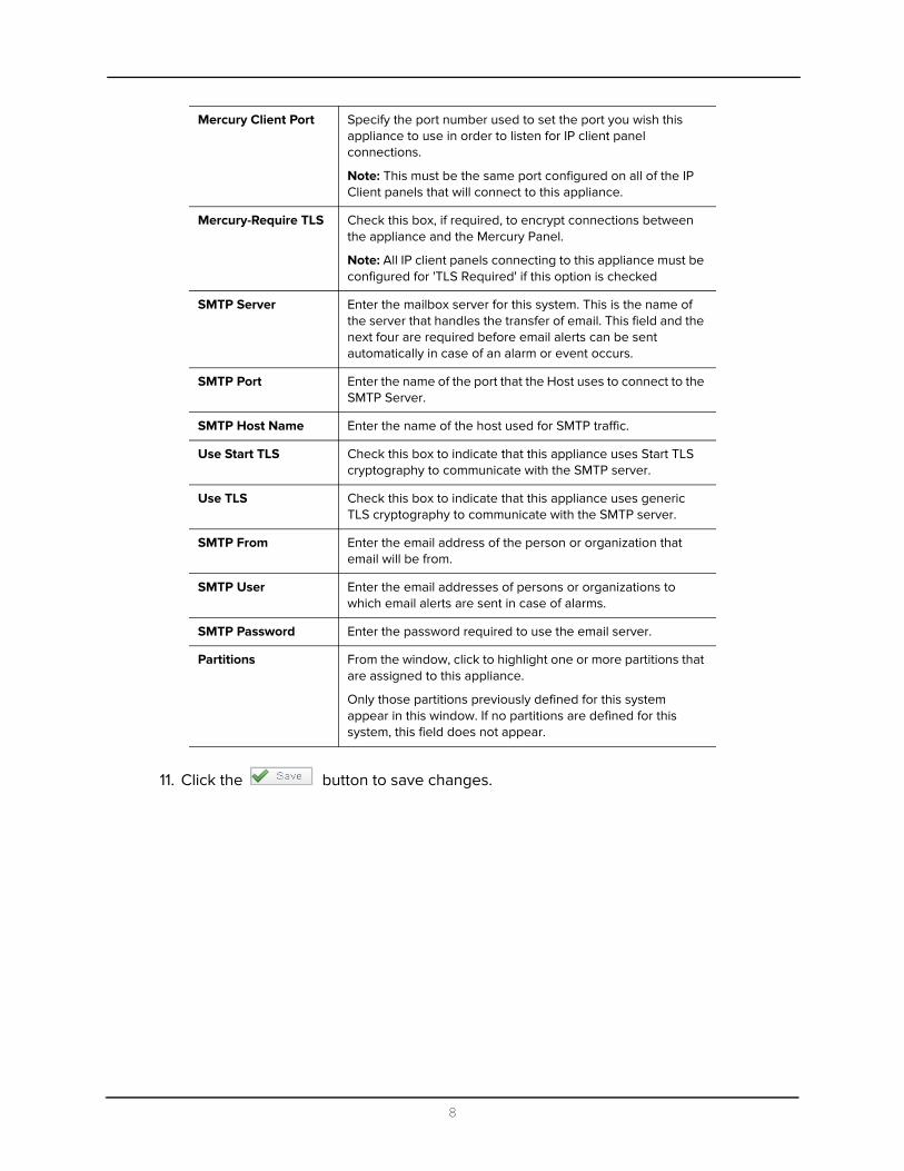
11. Click the button to save changes.
Mercury Client Port Specify the port number used to set the port you wish this appliance to use in order to listen for IP client panel connections.
Note: This must be the same port configured on all of the IP Client panels that will connect to this appliance.
Mercury-Require TLS Check this box, if required, to encrypt connections between the appliance and the Mercury Panel.
Note: All IP client panels connecting to this appliance must be configured for 'TLS Required' if this option is checked
SMTP Server Enter the mailbox server for this system. This is the name of the server that handles the transfer of email. This field and the next four are required before email alerts can be sent automatically in case of an alarm or event occurs.
SMTP Port Enter the name of the port that the Host uses to connect to the SMTP Server.
SMTP Host Name Enter the name of the host used for SMTP traffic.
Use Start TLS Check this box to indicate that this appliance uses Start TLS cryptography to communicate with the SMTP server.
Use TLS Check this box to indicate that this appliance uses generic TLS cryptography to communicate with the SMTP server.
SMTP From Enter the email address of the person or organization that email will be from.
SMTP User Enter the email addresses of persons or organizations to which email alerts are sent in case of alarms.
SMTP Password Enter the password required to use the email server.
Partitions From the window, click to highlight one or more partitions that are assigned to this appliance.
Only those partitions previously defined for this system appear in this window. If no partitions are defined for this system, this field does not appear.
8

12. Click the button.
13. Once the appliance reboots, click the About tab.
The About page appears like the following example.
The essential information about this appliance, including the appliance license string and key are displayed.
14. For initial setup, click the “View End User License Agreement Terms and Conditions” link.
First click the Save button then click the Reboot Appliance button.
EULA must be completed before you can install the hardware
9

The Software Terms and Conditions form appears like this example:
15. Review the terms then enter the name of this company, the name of the administrator or owner, and the title of the person whose name appears here, then click Back.
16. Reboot the appliance as explained in Step 10, then click Logout at the top of the page to log out of the appliance.
17. Log in and click on Appliance.
The Appliance property sheet appears.
18. Click on the Ports tab.
The Ports page appears like this example:
19. Click on the Port-1 name.
The Port-1 edit page appears like this example:
20.At the ‘IP Address’ field, enter the selected static IP address.
This IP address should be in the range of your LAN. If needed, consult your IT administrator for an appropriate address.
10
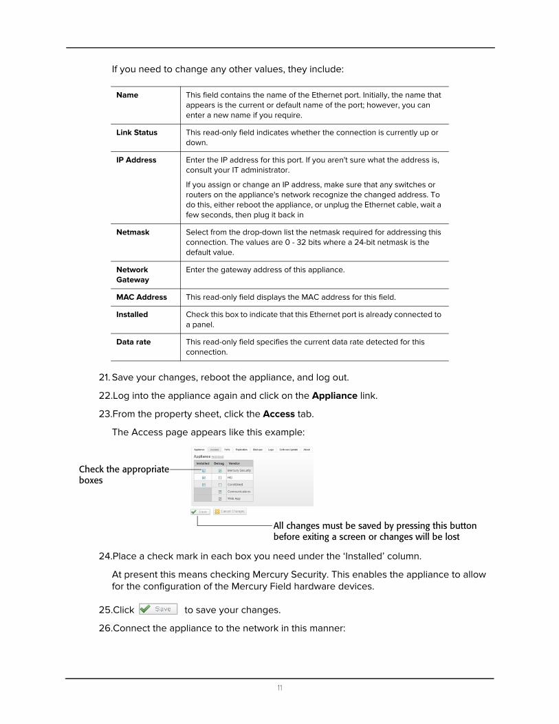
If you need to change any other values, they include:
21. Save your changes, reboot the appliance, and log out.
22.Log into the appliance again and click on the Appliance link.
23.From the property sheet, click the Access tab.
The Access page appears like this example:
24.Place a check mark in each box you need under the ‘Installed’ column.
At present this means checking Mercury Security. This enables the appliance to allow for the configuration of the Mercury Field hardware devices.
25.Click to save your changes.
26.Connect the appliance to the network in this manner:
Name This field contains the name of the Ethernet port. Initially, the name that appears is the current or default name of the port; however, you can enter a new name if you require.
Link Status This read-only field indicates whether the connection is currently up or down.
IP Address Enter the IP address for this port. If you aren't sure what the address is, consult your IT administrator.
If you assign or change an IP address, make sure that any switches or routers on the appliance's network recognize the changed address. To do this, either reboot the appliance, or unplug the Ethernet cable, wait a few seconds, then plug it back in
Netmask Select from the drop-down list the netmask required for addressing this connection. The values are 0 - 32 bits where a 24-bit netmask is the default value.
Network Gateway
Enter the gateway address of this appliance.
MAC Address This read-only field displays the MAC address for this field.
Installed Check this box to indicate that this Ethernet port is already connected to a panel.
Data rate This read-only field specifies the current data rate detected for this connection.
Check the appropriateboxes
All changes must be saved by pressing this buttonbefore exiting a screen or changes will be lost
11

a. Remove the crossover cable and move the appliance to its required position in the system.
b. Using a standard Ethernet cable, connect one end of the RJ-45 to an available RJ-45 port on the appliance.
c. Connect the other end of the Ethernet cable to the network.
If this is a Virtual appliance, ignored this step.
NOTE: Access Control Manager only supports connectivity to Mercury controllers through IP. Serial connectivity to these panels is not currently supported.
Express
Enterprise
12

2
PanelsAfter setting up the appliance, your next step is to configure the panels to which this appliance is connected. For this document, we are only interested in Mercury Security panels.To configure Mercury Security panels:
1. From the icon task bar of the home page, click on Physical Access then click on Panels.
2. Click the button to add a panel.
The Panel Add page appears like this example:
3. Assign the new panel a name, choose an appliance, and select Mercury for vendor type.
New fields appear like this example:
4. Place a check mark in the ‘Installed’ checkbox.
5. At the ‘Model’ pick list, select your panel model then choose your time zone.
While Mercury panels appear in this list, you can also configure Lenel panels. A table of equivalency is shown below:
Lenel Mercury
LNL-500 SCP-C
LNL-1000 SCP-2
LNL-2000 SCP-E
LNL-2200 EP1502
LNL-3300 EP2500
LNL-2210 EP1501
LNL-1100 MR16in
LNL-1200 MR16out
13
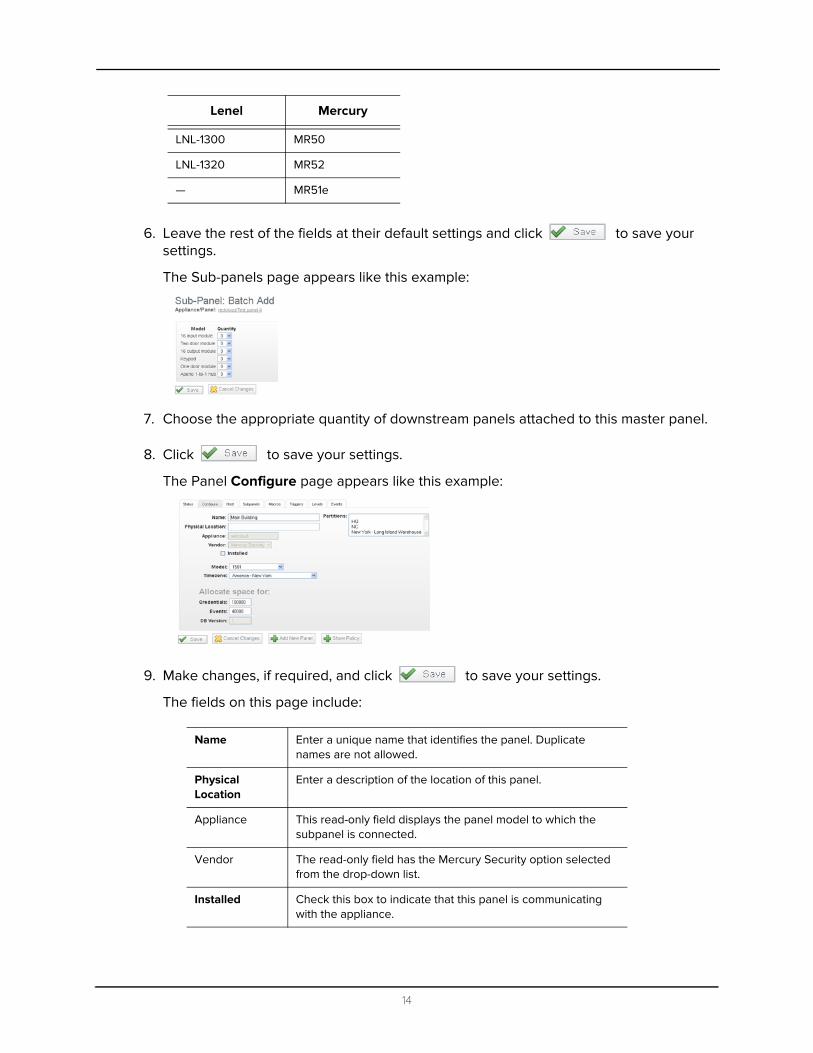
6. Leave the rest of the fields at their default settings and click to save your settings.
The Sub-panels page appears like this example:
7. Choose the appropriate quantity of downstream panels attached to this master panel.
8. Click to save your settings.
The Panel Configure page appears like this example:
9. Make changes, if required, and click to save your settings.
The fields on this page include:
LNL-1300 MR50
LNL-1320 MR52
— MR51e
Name Enter a unique name that identifies the panel. Duplicate names are not allowed.
Physical Location
Enter a description of the location of this panel.
Appliance This read-only field displays the panel model to which the subpanel is connected.
Vendor The read-only field has the Mercury Security option selected from the drop-down list.
Installed Check this box to indicate that this panel is communicating with the appliance.
Lenel Mercury
14
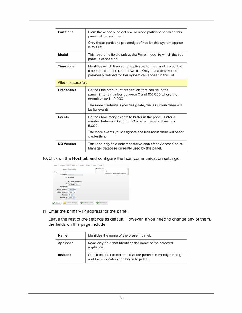
10. Click on the Host tab and configure the host communication settings.
11. Enter the primary IP address for the panel.
Leave the rest of the settings as default. However, if you need to change any of them, the fields on this page include:
Partitions From the window, select one or more partitions to which this panel will be assigned.
Only those partitions presently defined by this system appear in this list.
Model This read-only field displays the Panel model to which the sub panel is connected.
Time zone Identifies which time zone applicable to the panel. Select the time zone from the drop-down list. Only those time zones previously defined for this system can appear in this list.
Allocate space for:
Credentials Defines the amount of credentials that can be in the panel. Enter a number between 0 and 100,000 where the default value is 10,000.
The more credentials you designate, the less room there will be for events.
Events Defines how many events to buffer in the panel. Enter a number between 0 and 5,000 where the default value is 5,000.
The more events you designate, the less room there will be for credentials.
DB Version This read-only field indicates the version of the Access Control Manager database currently used by this panel.
Name Identities the name of the present panel.
Appliance Read-only field that Identities the name of the selected appliance.
Installed Check this box to indicate that the panel is currently running and the application can begin to poll it.
15

12. Click to save your settings.
Once the previous settings have been saved, the system returns to the Panels Listing page. You should see that the panel you created is online.
13. Click on the Panel name to get to Panel Edit screen with the Panel Status page displays.
14. On the Status page, click on the Firmware button like this example:
Partitions From the window, select one or more partitions to which this panel will be assigned.
Only those partitions presently defined by this system appear in this list.
IP Address Enter the IP address of this panel.
Reply Timeout From the list, select the number of milliseconds this panel is allowed to wait for a reply from the primary Access Control Manager host.
Offline Timeout From the list, select the number of milliseconds this panel can remain offline (disconnected from the host) before the panel attempts to contact an alternative host, if one exists.
Retries From the list, select the number of retries allowed before this panel stops polling the host and attempts to connect the alternative host, if one is configured.
Poll Delay Defines the number of milliseconds it is required for the panel to wait between polls.
Click this button
16

The Firmware listing like this example:
15. Locate the firmware for the panel you installed and configured, then click the green check mark to download the firmware to the panel.
NOTE: For instructions on copying firmware to your host computer, refer to the Access Control Manager online help.
The system asks you to confirm that you want to download the firmware to the panel.
16. Click Yes.
The firmware is installed. This takes approximately five minutes.
17. Once the firmware is installed, click the Reset/Download button and allow one minute for the panel to reset and an additional two minutes for the parameters and tokens to download.
Panel Add Summary
To summarize the panel configuration process:
1. Add the Panel and configure required settings
2. Once installed go to the status screen for the panel and install the latest firmware (approximately five minutes).
3. Once the firmware is installed click the reset button and allow 1 minute for the panel to reset.
4. After the panel has completed resetting, click the download parameters button and allow the parameters to download which takes approximately two minutes.
5. After the parameters are completed downloading click the download tokens button.
Click this button
17

6. Proceed to add Areas (page 19).
If you do not require areas in order to define the doors, you can skip Areas and go directly to Doors (page 21).
18
3
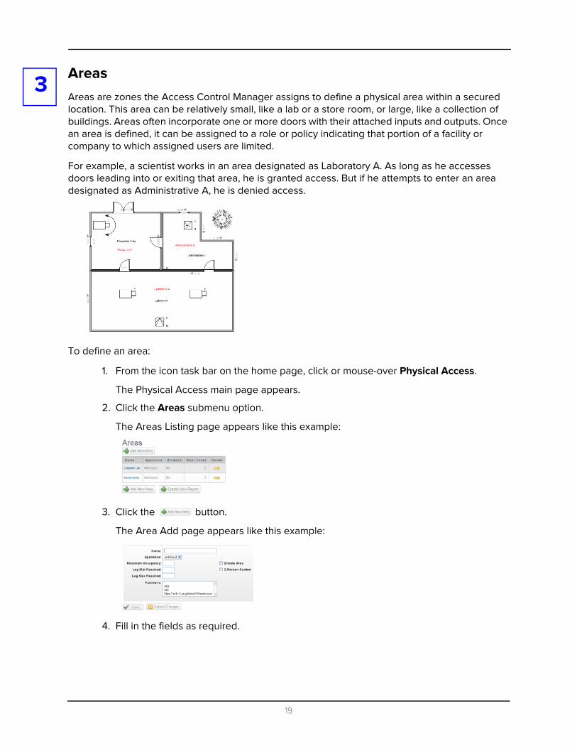
AreasAreas are zones the Access Control Manager assigns to define a physical area within a secured location. This area can be relatively small, like a lab or a store room, or large, like a collection of buildings. Areas often incorporate one or more doors with their attached inputs and outputs. Once an area is defined, it can be assigned to a role or policy indicating that portion of a facility or company to which assigned users are limited.For example, a scientist works in an area designated as Laboratory A. As long as he accesses doors leading into or exiting that area, he is granted access. But if he attempts to enter an area designated as Administrative A, he is denied access.
To define an area:
1. From the icon task bar on the home page, click or mouse-over Physical Access.
The Physical Access main page appears.
2. Click the Areas submenu option.
The Areas Listing page appears like this example:
3. Click the button.
The Area Add page appears like this example:
4. Fill in the fields as required.
19

These fields include:
5. Click to save these values.
A message appears “Area was successfully created” and the Areas Listing page reappears with the newly added area on the list.
Appliance From the drop-down pick list, select one of the existing appliances in which this area appears.
Only those appliances currently defined for this system appear in this list.
Name Enter the name of this area
Maximum Occupancy
Enter the maximum number of cardholders allowed in this area at a specified time.
Log Min Reached Record a transaction when the minimum count for this area is reached.
Log Max Reached Record a transaction when the maximum count for this area is reached.
Enable Area Check this box to enable use of this area definition.
2-Person Control Check this box to indicate a two-person rule is imposed for this area.
When checked, two or more people must be in the area at times when occupied. When the area is empty, two valid cardholders must present their credentials to the entry reader before entry is granted. Once occupied by two or more people, individual access can be granted. The same rules apply for exit until two cardholders are left in the area; at this point, both cardholders must present their credentials and exit the area together.
Partitions Select one or more partitions from the partitions list. This includes those partitions in this area definition.
Only those partitions currently defined for this system appear in this list.
20

4
DoorsAfter you have configured both the appliance and the panels it controls, it is time to create and configure each door associated with the created panels.To create and configure doors:
1. From the icon task bar on the home page, click Physical Access.
2. Click Doors.
The Doors Listing page appears like this example:
3. Click the button.
The Door Add screen appears like this example:
4. Enter the following information:
• Door Name• An Alternate name (optional)• Location (optional)
5. From the ‘Appliance’ pick list, select the appliance to which this door is connected.
6. From the ‘Vendor’ pick list, select the vendor.
In this case, you should select Mercury Security.
21
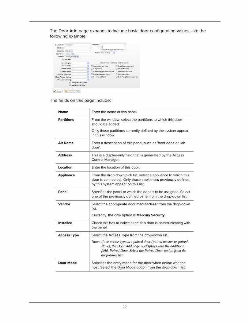
The Door Add page expands to include basic door configuration values, like the following example:
The fields on this page include:
Name Enter the name of this panel.
Partitions From the window, select the partitions to which this door should be added.
Only those partitions currently defined by the system appear in this window.
Alt Name Enter a description of this panel, such as 'front door' or 'lab door'.
Address This is a display-only field that is generated by the Access Control Manager.
Location Enter the location of this door.
Appliance From the drop-down pick list, select a appliance to which this door is connected. Only those appliances previously defined by this system appear on this list.
Panel Specifies the panel to which the door is to be assigned. Select one of the previously defined panel from the drop-down list.
Vendor Select the appropriate door manufacturer from the drop-down list.
Currently, the only option is Mercury Security.
Installed Check this box to indicate that this door is communicating with the panel.
Access Type Select the Access Type from the drop-down list.
Note: If the access type is a paired door (paired master or paired slave), the Door Add page re-displays with the additional field, Paired Door. Select the Paired Door option from the drop-down list.
Door Mode Specifies the entry mode for the door when online with the host. Select the Door Mode option from the drop-down list.
22

Offline Mode Specifies the entry mode used for the door if the door controller is no longer communicating with the panel.
Note: In many cases, the limited memory of most readers in offline mode requires a very simple solution to entry or exit, such as use of a facility code.
Select the Offline Mode option from the drop-down list.
Custom mode From the drop-down list, select the special mode to use during a time zone specified in the 'Custom Schedule' field. For example, during normal working hours, it might only be necessary to use a card only entry at a particular door, whereas after midnight, you would enforce PIN code and card.
Custom Schedule
From the drop-down list, select the interval during which the custom mode specified above is activated. Only those time zones previously defined for this system appear in this list.
Mask Forced During
From the drop-down list, select the time during which this door is masked even when a forced open condition is detected. Only those schedules previously defined for this system appear in this list.
Mask Held During
From the drop-down list, select the time during which Door Held Open alarms from this door will be masked. Only those schedules previously defined for this system appear in this list.
Always Mask Forced
From the drop-down box, select TRUE to specify that Door Forced Open alarms at this door are always masked. Normally, this box is blank.
Always Mask Held
From the drop-down box, select TRUE to specify that Door Held Open alarms at this door are always masked. Normally, this box is blank.
Door Processing Attributes
Log Grants Right Away
When this box is checked, the system logs an extra event as soon as there is a grant (that is, before entry / no entry is determined). This event is not turned into a Access Control Manager event. Check this box in order to initiate local I/O in the panel using the panel triggers.
Certain customers may have a trigger they want to fire (to execute a macro) as soon as there is a grant, but before entry / no entry is determined.
Deny Duress If a user indicates duress at a door, checking this box denies access.
Don't Pulse Door Strike on REX
Check this box to disable the pulse of the door strike output when the request-to-exit button is pressed. This can be used to effect a 'quiet' exit. If this box is not checked, the output is pulsed.
Require Two Card Control
Check this box to specify that two tokens are required to open this door. This enforces two-person rule at a specified door.
23

7. Choose the following for basic door configurations values:
• Access Type: Single• Door Mode: Card Only• Offline Mode: Facility Code Only• Unlock During: Never Active
8. In the ‘Door Processing Attributes’ section, choose the appropriate settings.
9. Click to save your settings.
The Operations page appears like this example:
The fields on this page include:
Door Forced Filter
Check this box to enable the filter feature for door forced alarms. There are instances when a door is either slow to close or is slammed shut and bounces open for a few seconds. With this filter, the monitor allows three seconds for a door to close before issuing an alarm.
Log All Access as Used
Check this box to log all access grant transactions as if the person used the door. If this box is not checked, the door determines if it was opened and will distinguish if the door was used or not used for grant.
Detailed Events Check this box to generate detailed events of all hardware at the door including door position masking, timer expirations and output status. Typically, five to ten detailed transactions will be generated for each grant transactions. During the normal course of operation, most guards don't need to see extensive reports on events; however, after hours, it is often useful to see every detail.
Enable Cipher Mode
Check this box to enable cipher mode. Cipher mode allows the operator to enter card number digits at the door’s keypad.
Use Shunt Relay Check this box to enable the use of a shunt relay for this door.
Do Not Log Rex Transactions
Check this box to indicate that return-to-exit transactions are not logged by the system.
Name Identifies the door. Enter a unique name that identifies the door.
24

Alt Name Identifies an alternate name for the door. If there is an additional name the door is identified by, enter this alternate name.
Location Identifies the location of the door. Enter a description of the door’s location.
Appliance Identifies the appliance of the door. This is a display only field when in edit mode.
Vendor Identifies the vendor of the door. This is a display only field when in edit mode.
Installed Check this box to indicate that this door is currently connected and communicating with the panel and appliance.
Partitions From the window, select the partitions to which this door should be added.
Only those partitions currently defined by the system appear in this window.
Panel Specifies the panel the door is assigned to. This is a display only field when editing the hardware (the panel can be changed when editing the door operations).
APB Mode Indicates the anti-passback mode for the door. Select the APB Mode from the drop-down list. The available options are:
No Selection – The specified door is not involved in APB at all. Grants do not take APB into consideration at all.
Soft area APB – The specified door should have an area entering and area leaving configured for it.
Hard area APB – The specified door should have an area entering and area leaving configured for it.
Door-based timed APB – The specified door should not have an area entering or area leaving configured for it. There should be a timeout value configured for the door (a value entered in the 'APB Delay' field).
Token-based timed APB – The specified door should not have an area entering or area leaving configured for it. There should be a timeout value configured for the door (a value entered in the 'APB Delay' field).
Timed area APB – The specified door should have an area entering, area leaving, and timeout configured for it.
APB Delay Specifies the number of seconds before another entry is allowed. Enter the number of seconds.
Area Entering Identifies the area the user enters when entering through the door. If no area is specified, any location is valid. Select the area from the drop-down list. Only those areas currently defined for this system appear in this list.
Area Leaving Identifies the area the user moves into when exiting the door. Select the area from the drop-down list. In addition to the Don't Care option, only those areas currently defined for this system appear in this list.
25
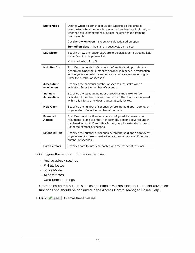
10. Configure these door attributes as required:
• Anti-passback settings• PIN attributes• Strike Mode• Access times• Card format settings
Other fields on this screen, such as the ‘Simple Macros’ section, represent advanced functions and should be consulted in the Access Control Manager Online Help.
11. Click to save these values.
Strike Mode Defines when a door should unlock. Specifies if the strike is deactivated when the door is opened, when the door is closed, or when the strike timer expires. Select the strike mode from the drop-down list.
Cut short when open – the strike is deactivated on open
Turn off on close – the strike is deactivated on close.
LED Mode Specifies how the reader LEDs are to be displayed. Select the LED mode from the drop-down list.
Your choice is 1, 2, or 3.
Held Pre-Alarm Specifies the number of seconds before the held open alarm is generated. Once the number of seconds is reached, a transaction will be generated which can be used to activate a warning signal. Enter the number of seconds.
Access time when open
Specifies the minimum number of seconds the strike will be activated. Enter the number of seconds.
Standard Access time
Specifies the standard number of seconds the strike will be activated. Enter the number of seconds. If the door is not opened within this interval, the door is automatically locked.
Held Open Specifies the number of seconds before the held open door event is generated. Enter the number of seconds.
Extended Access
Specifies the strike time for a door configured for persons that require more time to enter. For example, persons covered under the Americans with Disabilities Act may require extended access. Enter the number of seconds.
Extended Held Specifies the number of seconds before the held open door event is generated for tokens marked with extended access. Enter the number of seconds.
Card Formats Specifies card formats compatible with the reader at the door.
26

The Hardware page appears like this example:
The fields on this page include:
If a sub-panel has been assigned as the option for any of the following
fields then saved, the edit sub-panel icon, , will appear as shown in this example:
Click the icon to edit the sub-panel associated with the currently displayed option.
There are three screens that can appear:
• If you click at the 'Reader' or 'Alt Reader' pick list, a sub-panel reader edit page can appear.
• If you click at the 'Door POS' or the two 'REX' pick lists, a sub-panel door edit page can appear.
• If you click at the 'Strike' pick list, a sub-panel output edit page can appear.
Reader Select the reader you require from the drop-down list. This identifies the subpanel and port number connected to the primary reader.
If you select a sub-panel, the appears to the right of this selection. Click to bring up the edit page for this option.
Door POS Select the option you require from the drop-down list. This identifies the subpanel and input number connected to the door position switch.
If you select a sub-panel, the appears to the right of this selection. Click to bring up the edit page for this option.
Strike Select the option you require from the drop-down list. This identifies the subpanel and output number connected to the door strike.
If you select a sub-panel, the appears to the right of this selection. Click to bring up the edit page for this option.
27

12. On this page, you can configure these door attributes:
• Reader (entry and/or exit)• REX (Request-to-exit button or bar)• Door Contact• Strike
If you have made selections in any of the six bottom fields, notice the pencil/edit icon,
, to the right of the Reader, Alt Reader, Door POS, Rex, and Strike pick lists.
This edit icon enables you to bring up and edit the properties for the specified device as shown in this door example:
For more on the fields each of these pages contains, refer to the Access Control Manager online help.
13. Click to save these settings.
Alt Reader Select the option you require from the drop-down list. This identifies the subpanel and reader number of a secondary reader. A secondary reader is typically used for the secure side door or a biometric.
If you select a sub-panel, the appears to the right of this selection. Click to bring up the edit page for this option.
REX #1 Select the option you require from the drop-down list. This identifies the subpanel and input number connected to the first request-to-exit switch.
If you select a sub-panel, the appears to the right of this selection. Click to bring up the edit page for this option.
REX #2 Select the option you require from the drop-down list. This identifies the subpanel and output number connected to the second request-to-exit switch.
If you select a sub-panel, the appears to the right of this selection. Click to bring up the edit page for this option.
Click on the appropriate button to bring up the settings for the specified input/output device
28

The Interlocks page appears like this example:
Interlocks allow you to configure inputs and outputs connected to this door.
NOTE: For more on interlocks, refer to the Access Control Manager online help.
14. Click the Cameras tab.
The Cameras page appears like this example:
The fields on this page include:
15. Proceed to additional pages as required.
• The Interlocks page provides a means to trigger this door using an alarm or event from another part of the system.
Camera Type From the drop-down list, select the type of camera you want to add. You can currently select from these options:
• Network
• Exacq camera server
• Pelco camera server
• Avigilon server
• Salient server
• Milestone server
The ‘Available’ window is populated with those cameras that fit this definition.
Available From the window, select one or more cameras that are connected to
this door then click . The camera(s) are transferred to the Members window.
Only those cameras previously connected to and configured for this system's network can appear in this window.
Members This window displays all cameras previously added to this door definition.
29
• The Access page is a quick reference by door to show what access groups, roles and identities have access to that door.
• The Events page provides a record of both local and global events this door has detected.
• The Transactions page displays a list of all transactions that have included use of this door.
For more on all these functions, refer to the online help.
16. When you’ve finished entering all relevant values on the required pages, click
to save these settings.
Perform this same step-wise procedure for each door you need to define for this panel.
30
5
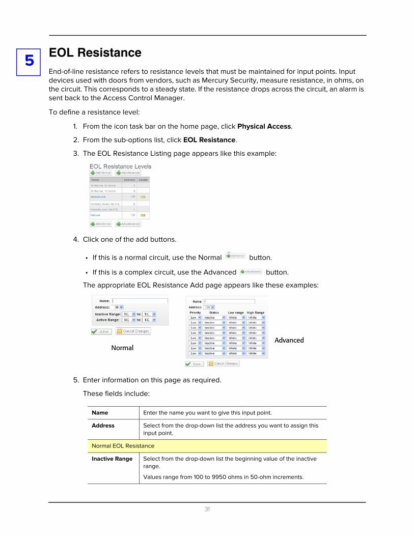
EOL ResistanceEnd-of-line resistance refers to resistance levels that must be maintained for input points. Input devices used with doors from vendors, such as Mercury Security, measure resistance, in ohms, on the circuit. This corresponds to a steady state. If the resistance drops across the circuit, an alarm is sent back to the Access Control Manager.To define a resistance level:
1. From the icon task bar on the home page, click Physical Access.
2. From the sub-options list, click EOL Resistance.
3. The EOL Resistance Listing page appears like this example:
4. Click one of the add buttons.
• If this is a normal circuit, use the Normal button.
• If this is a complex circuit, use the Advanced button.
The appropriate EOL Resistance Add page appears like these examples:
5. Enter information on this page as required.
These fields include:
Name Enter the name you want to give this input point.
Address Select from the drop-down list the address you want to assign this input point.
Normal EOL Resistance
Inactive Range Select from the drop-down list the beginning value of the inactive range.
Values range from 100 to 9950 ohms in 50-ohm increments.
NormalAdvanced
31
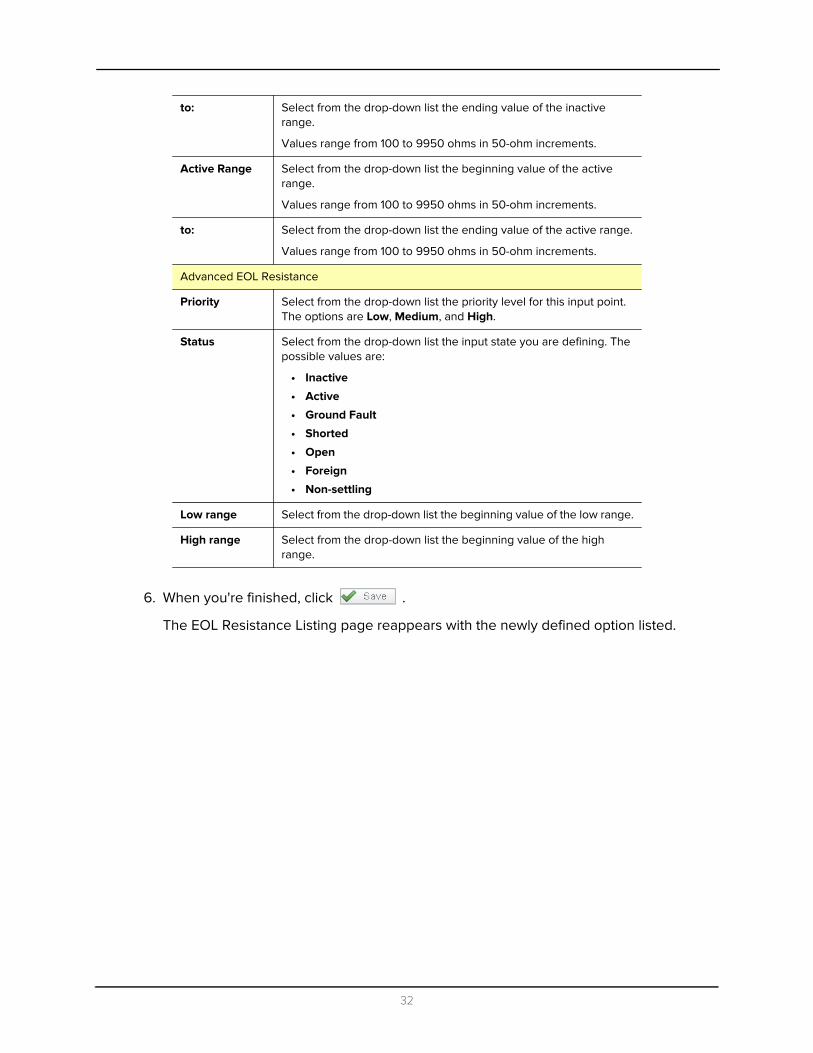
6. When you're finished, click .
The EOL Resistance Listing page reappears with the newly defined option listed.
to: Select from the drop-down list the ending value of the inactive range.
Values range from 100 to 9950 ohms in 50-ohm increments.
Active Range Select from the drop-down list the beginning value of the active range.
Values range from 100 to 9950 ohms in 50-ohm increments.
to: Select from the drop-down list the ending value of the active range.
Values range from 100 to 9950 ohms in 50-ohm increments.
Advanced EOL Resistance
Priority Select from the drop-down list the priority level for this input point. The options are Low, Medium, and High.
Status Select from the drop-down list the input state you are defining. The possible values are:
• Inactive
• Active
• Ground Fault
• Shorted
• Open
• Foreign
• Non-settling
Low range Select from the drop-down list the beginning value of the low range.
High range Select from the drop-down list the beginning value of the high range.
32

6
SchedulesA schedule is a time period defined for use by the system. It is an editable, reusable time template that can be used to control such things as when a door is accessible or when a device is activated. A user’s access privileges are the result of a three-way relationship that is created between a• group of users• secured device• schedule
To create a new schedule:
1. From the Setup Links section of the home page, select Settings.
The Schedule Listing page appears like this example:
By default only the ‘24-Hour Active’ and ‘Never Active’ options appear. These are the only options that cannot be changed or deleted.
2. Click the button.
The Schedule Add page appears like this example:
3. Enter information as required.
The available fields include:
Name Enter the name of the schedule.
Enter a brief, meaningful name for the schedule, such as “Graveyard Shift”.
33
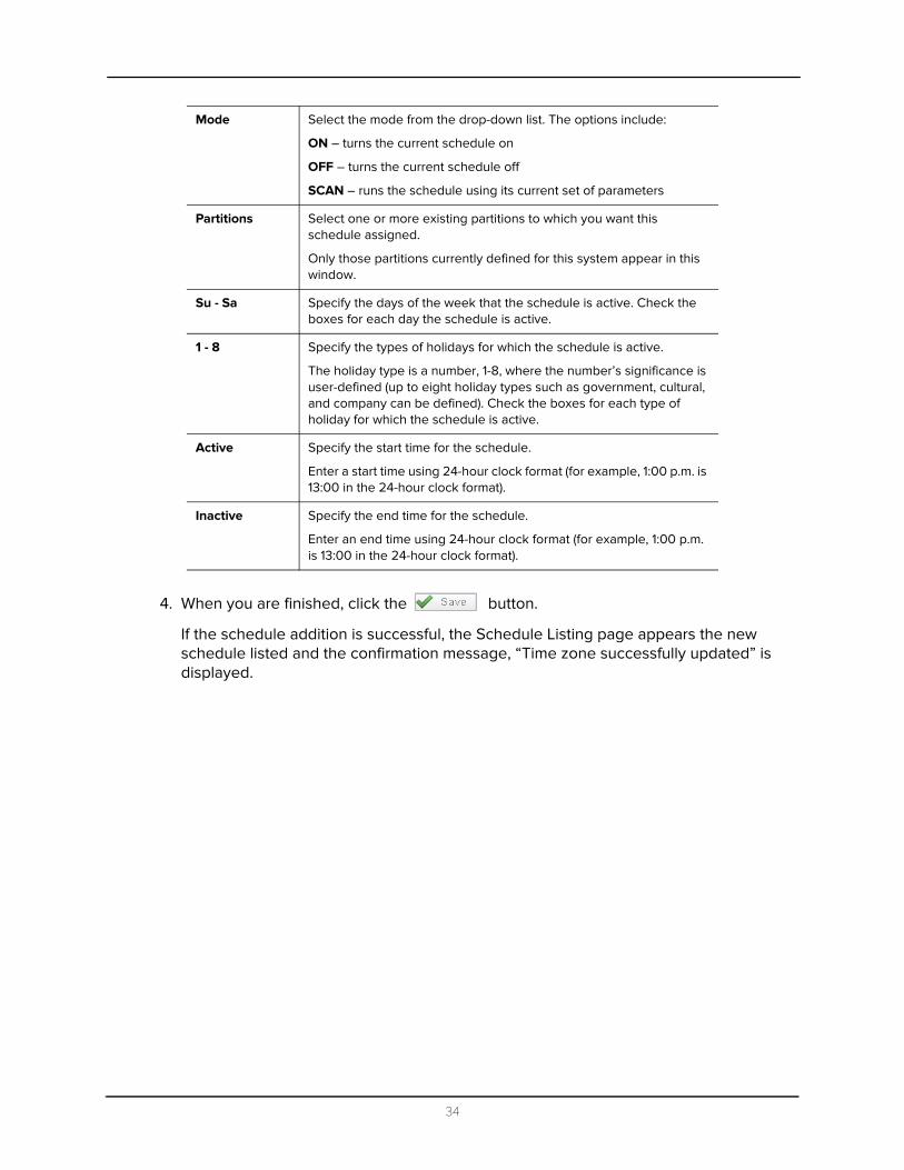
4. When you are finished, click the button.
If the schedule addition is successful, the Schedule Listing page appears the new schedule listed and the confirmation message, “Time zone successfully updated” is displayed.
Mode Select the mode from the drop-down list. The options include:
ON – turns the current schedule on
OFF – turns the current schedule off
SCAN – runs the schedule using its current set of parameters
Partitions Select one or more existing partitions to which you want this schedule assigned.
Only those partitions currently defined for this system appear in this window.
Su - Sa Specify the days of the week that the schedule is active. Check the boxes for each day the schedule is active.
1 - 8 Specify the types of holidays for which the schedule is active.
The holiday type is a number, 1-8, where the number’s significance is user-defined (up to eight holiday types such as government, cultural, and company can be defined). Check the boxes for each type of holiday for which the schedule is active.
Active Specify the start time for the schedule.
Enter a start time using 24-hour clock format (for example, 1:00 p.m. is 13:00 in the 24-hour clock format).
Inactive Specify the end time for the schedule.
Enter an end time using 24-hour clock format (for example, 1:00 p.m. is 13:00 in the 24-hour clock format).
34

7
HolidaysHolidays are those days during the year when normal security policy may not be followed, either because it is a vacation or because a different entry and exit pattern is observed. Such days as Christmas and New Year's Day are examples of holidays.To add a new holiday:
1. From the Setups section of the home page, click or mouse-over the Settings option.
2. From the drop-down option list, click the Holidays sub-option.
The Holiday Listing page appears like this example:
By default, no vacations appear in this list initially.
3. Click on the button.
The Holiday Add page appears like the following example:
4. Enter information about the holiday as required.
The available fields include:
Name Identifies the holiday.
Enter a brief, meaningful name for the holiday, such as “Labor Day.”
Date Identifies the first date of the holiday.
Enter MM/DD/YYYY or click on the field to open a pop-up calendar and select the date on which the holiday starts.
Additional Days Identities the additional consecutive days this holiday is active. A setting of 0 indicates that the holiday is on for the single specified day only.
Enter the number of consecutive days for this holiday.
35

5. When you're finished, click the button.
The Holiday Listing page reappears with the new holiday listed and the confirmation message “Holiday was successfully created” displayed.
Partitions From the window, select one or more partitions to which you want to assign this holiday.
Only those partitions previously defined for this system appear in this window. If no partitions are defined for this system, this field does not appear.
Type Identifies the type of holiday.
The holiday type is a number from 1 to 8. This number is user-defined. For example, security might define 1 as government, 2 as cultural, and 3 as company.
Enter a value from 1 – 8.
36
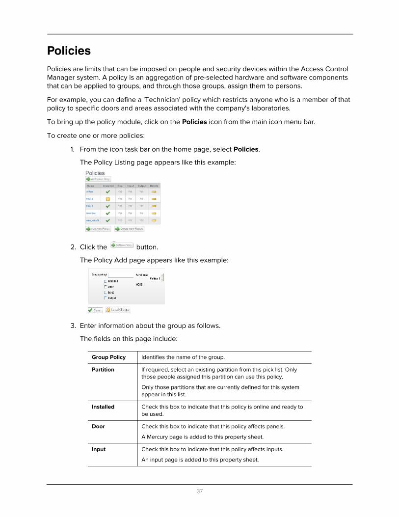
PoliciesPolicies are limits that can be imposed on people and security devices within the Access Control Manager system. A policy is an aggregation of pre-selected hardware and software components that can be applied to groups, and through those groups, assign them to persons.
For example, you can define a 'Technician' policy which restricts anyone who is a member of that policy to specific doors and areas associated with the company's laboratories.
To bring up the policy module, click on the Policies icon from the main icon menu bar.
To create one or more policies:
1. From the icon task bar on the home page, select Policies.
The Policy Listing page appears like this example:
2. Click the button.
The Policy Add page appears like this example:
3. Enter information about the group as follows.
The fields on this page include:
Group Policy Identifies the name of the group.
Partition If required, select an existing partition from this pick list. Only those people assigned this partition can use this policy.
Only those partitions that are currently defined for this system appear in this list.
Installed Check this box to indicate that this policy is online and ready to be used.
Door Check this box to indicate that this policy affects panels.
A Mercury page is added to this property sheet.
Input Check this box to indicate that this policy affects inputs.
An input page is added to this property sheet.
37

4. Click the button.
The confirmation message, “Policy was successfully created.” displayed.
The Policy properties edit screen appears like this example:
Only those components you select on the policy page (plus the Mercury page) are represented on this screen.
5. Click each page in turn and make changes to that page as required.
For information on using the fields on other pages of this property sheet, refer to the Access Control Manager online help.
6. Click the button to save your changes and move to the next page.
7. When you’re finished, click the button to return to the listing page.
Output Check this box to indicate that this policy affects outputs.
An output page is added to this property sheet.
38

8
GroupsGroups combine one or more existing policies with the members (identities) who can use them.In order to create a group, you must first create one or more policies and one or more identities with which these policies are associated.
Policies can also be assigned to people through the Identities assignment feature.
In addition, the groups feature enables the operator to perform batch updates on groups associated with a particular identity profile.
NOTE: Groups should not be confused with Access Groups or Routing Groups which are concepts in Access Control Manager associated with Roles.
To create one or more groups:
1. From the icon task bar on the home page, click or mouse-over Policies.
The Policy Listing page appears.
2. From the sub-options bar, click Groups.
The Group Listing page appears like this example:
3. Click the button.
The Group Add page appears like this example:
4. Enter information about the group as follows.
The fields on this page include:
Name Identifies the name of the group.
Partitions If required, select one or more existing partitions from this pick list. Only those people assigned these partitions can use this group.
Only those partitions that are currently defined for this system appear in this list. If no partition is defined for this system, this field does not appear.
Policies If relevant, this field displays the policies associated with this group.
Members If relevant, this field displays the members associated with this policy group.
39
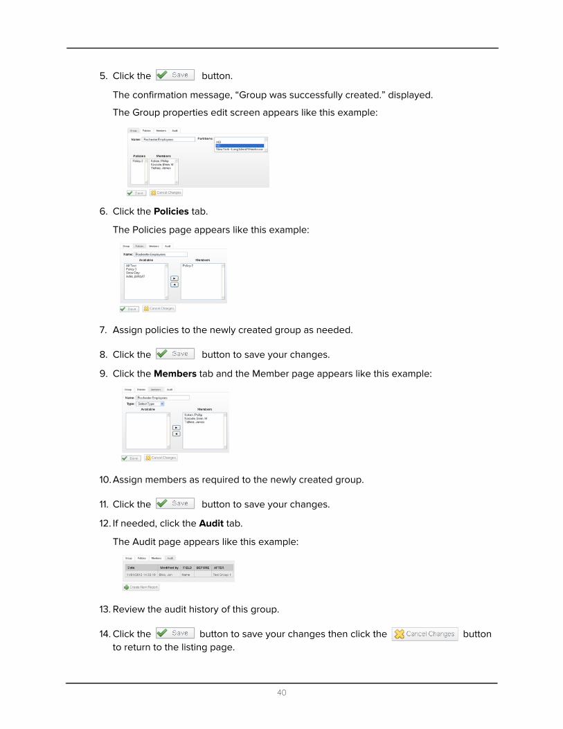
5. Click the button.
The confirmation message, “Group was successfully created.” displayed.
The Group properties edit screen appears like this example:
6. Click the Policies tab.
The Policies page appears like this example:
7. Assign policies to the newly created group as needed.
8. Click the button to save your changes.
9. Click the Members tab and the Member page appears like this example:
10. Assign members as required to the newly created group.
11. Click the button to save your changes.
12. If needed, click the Audit tab.
The Audit page appears like this example:
13. Review the audit history of this group.
14. Click the button to save your changes then click the button to return to the listing page.
40

9
Card FormatsReaders that control access to and exit from doors come in many varieties and use many different card protocols. The most commonly used card formats have been Wiegand and magnetic stripe; however, newer cards, using embedded chips, like Smart Cards, and proprietary formats have become more popular with the increase of security requirements.The Access Control Manager supports the most popular card formats and enables the qualified configurator or operator to define custom card formats to meet the requirements of many businesses and governmental entities. The standard 26-bit Wiegand card format is provided as a default setting.
To define additional card formats:
1. From the icon task bar on the home page, click or mouse-over the Physical Access option.
The available suboptions are displayed.
2. From the sub-options list, click Card Format.
The Card Formats Listing page appears.
3. Click .
The Card Format Add page appears as shown in this example:
4. Fill in this page as required.
These fields include:
Name The name of this card format
Card Format Type From the drop-down list, select the card format type. The current options are:
• Wiegand
• ABA Mag
The fields displayed below this change depending on which type is selected.
Facility Code The facility code of this card format.
41
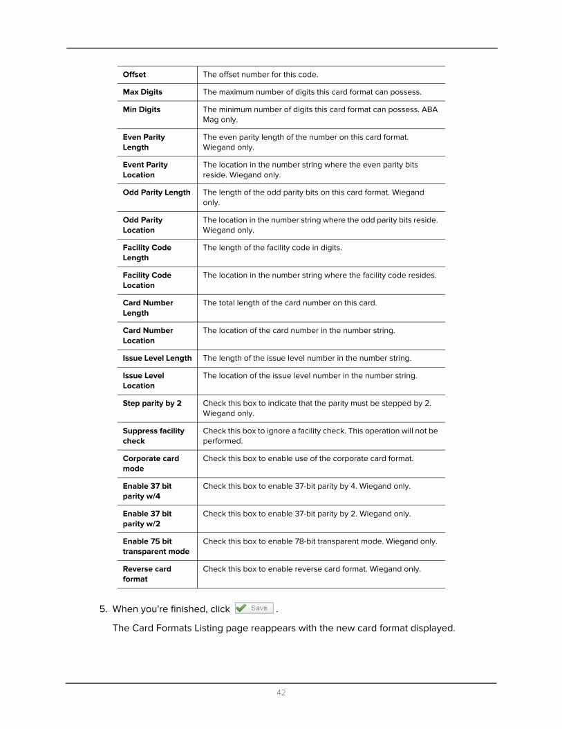
5. When you're finished, click .
The Card Formats Listing page reappears with the new card format displayed.
Offset The offset number for this code.
Max Digits The maximum number of digits this card format can possess.
Min Digits The minimum number of digits this card format can possess. ABA Mag only.
Even Parity Length
The even parity length of the number on this card format. Wiegand only.
Event Parity Location
The location in the number string where the even parity bits reside. Wiegand only.
Odd Parity Length The length of the odd parity bits on this card format. Wiegand only.
Odd Parity Location
The location in the number string where the odd parity bits reside. Wiegand only.
Facility Code Length
The length of the facility code in digits.
Facility Code Location
The location in the number string where the facility code resides.
Card Number Length
The total length of the card number on this card.
Card Number Location
The location of the card number in the number string.
Issue Level Length The length of the issue level number in the number string.
Issue Level Location
The location of the issue level number in the number string.
Step parity by 2 Check this box to indicate that the parity must be stepped by 2. Wiegand only.
Suppress facility check
Check this box to ignore a facility check. This operation will not be performed.
Corporate card mode
Check this box to enable use of the corporate card format.
Enable 37 bit parity w/4
Check this box to enable 37-bit parity by 4. Wiegand only.
Enable 37 bit parity w/2
Check this box to enable 37-bit parity by 2. Wiegand only.
Enable 75 bit transparent mode
Check this box to enable 78-bit transparent mode. Wiegand only.
Reverse card format
Check this box to enable reverse card format. Wiegand only.
42
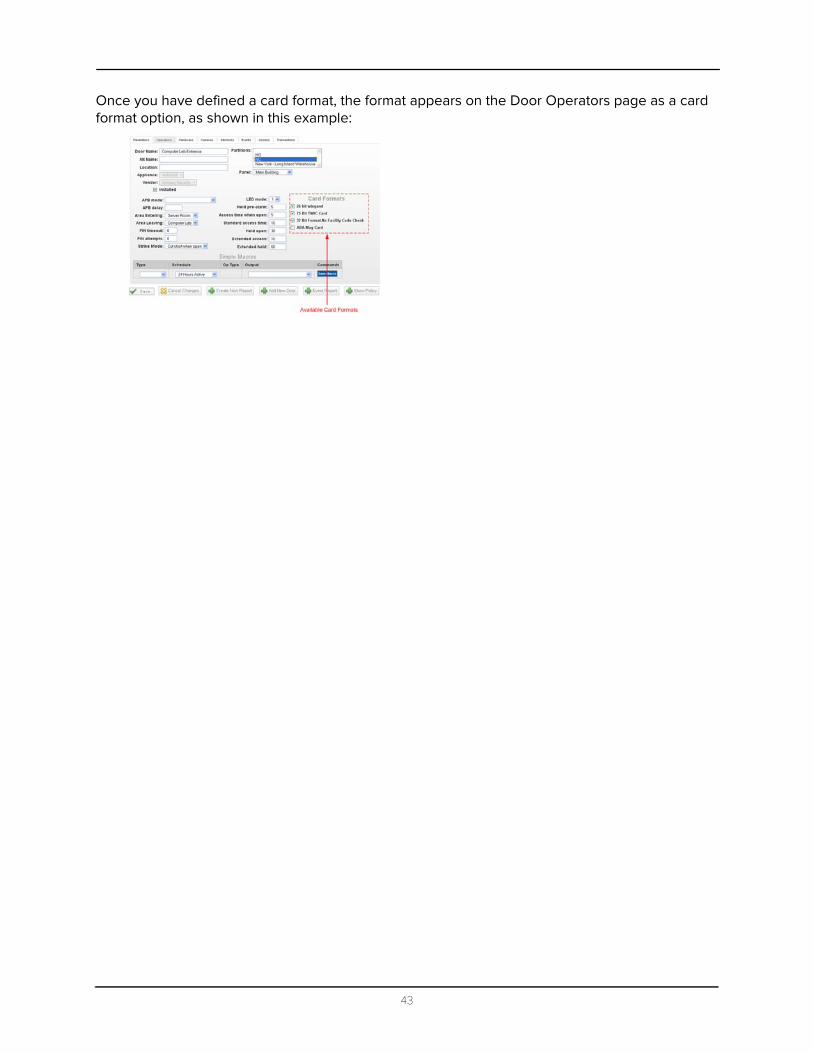
Once you have defined a card format, the format appears on the Door Operators page as a card format option, as shown in this example:
43

10
Event TypesEvent types are classifications of events that may occur during the operation of the Access Control Manager system. Event types are associated with specific event sources, such as doors, panels, and systems.NOTE: Particularly for initial installation, you can accept the default event types.
To add or change event types:
1. From the Setup Links section of the home page, click or mouse-over the Settings option.
2. From the available sub-options, select Event Types.
The Event Types Listing page appears like this example:
3. Do one of these:
• To add a new event type, click the button.• To edit an existing event type, click the event name.
The Add Event Type or Edit Event Type screen appears like this example:
4. Make changes to these fields as required.
Event Type Add Page Event Type Edit Page
44

These fields include:
5. When you're finished, click .
The Event Types Listing page reappears with a message saying the event was successfully changed.
Name Identifies the event type. Enter a brief, meaningful name for the event type, such as “Door Held Open”.
Suppress Schedule
Pick from the drop-down list a schedule that is suppressed when this event type is triggered.
Only those schedules currently defined for this system appear in this list.
Priority Specifies the alarm priority number. The Alarm Monitor stacks alarms on the screen according to their priority. Priority 1 alarms appear at the top of the screen, priority 2 alarms appear below the priority alarms, and so on.
The possible values are 1 - 99.
Masked Check this box to indicate that this event type is masked.
Logged Check this box to indicate that this event type is logged.
Alarm Check this box to indicate that this event type is alarmed.
Send Email to If this event type occurs, enter the email address to which an alert is sent.
Instructions If this event type occurs, enter instructions you require the qualified operator to follow.
These instructions are displayed in the alarm window.
Partitions If required, select one or more existing partitions from this pick list. Only those people assigned these partitions can view this event type.
Only those partitions that are currently defined for this system appear in this list. If no partition is defined for this system, this field does not appear.
45
11
EventsEvents include all messages and alarms issued by specific devices within the Access Control Manager system. Events are categorized by Event Types within Access Control Manager. Both events and event types can be modified or added as required for a specific installation.NOTE: Particularly for initial installation, you can accept the default events.
All available events are provided by default. You cannot create additional events; however, you can edit existing events.
To change one or more events:
1. From the icon task bar of the home page, click the Physical Access option.
The Physical Access Listing page appears.
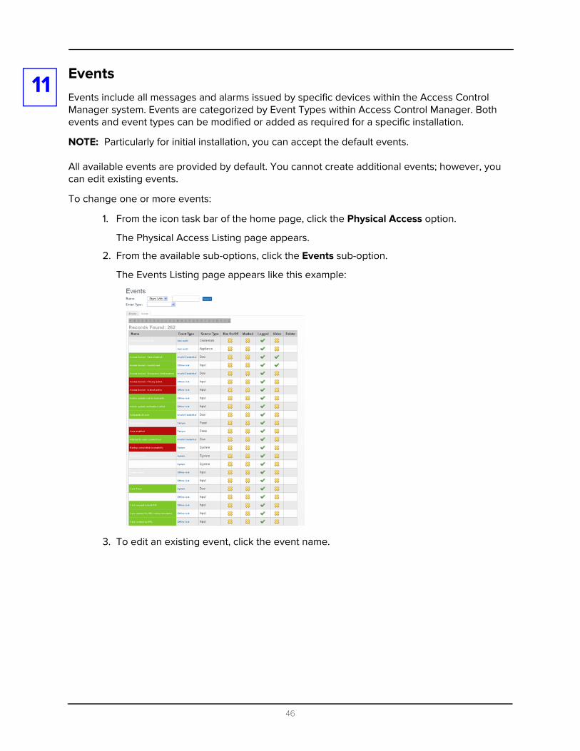
2. From the available sub-options, click the Events sub-option.
The Events Listing page appears like this example:
3. To edit an existing event, click the event name.
46

The Edit Event screen appears like this example:
4. Make changes to these fields as required.
These fields include:
Name Enter a name for this event.
Return Enter a name for the return-to-normal (RTN) event.
Event Type Select from the drop-down list the event type for this event.
Only those event types current defined for this system appear in this list.
Source Type Select from the drop-down list the device where this event originates.
Priority Specify the priority of this event. The Alarm Monitor stacks alarms on the screen
according to their priority. Priority 1 alarms appear at the top of the screen, priority 2 alarms appear below the priority alarms, and so on.
The priority range is 0 - 99.
Suppress Time From the drop-down list, select the time period during which this event is not reported.
Only those time periods currently defined for this system appear in this list.
Instructions Type instructions for handling this event. These instructions will appear on the operator's panel whenever this event occurs.
Email Enter the email addresses of all those people who should be notified when this event occurs.
You can enter more than one email address
Return Event Select from the drop-down list the event type for this RTN event.
Only those event types current defined for this system appear in this list.
Return Priority Enter the priority number of this event.
The priority range is 0 - 99.
Has on/off Check this box to indicate that this event is a toggle, involving an on/off switch logic.
47
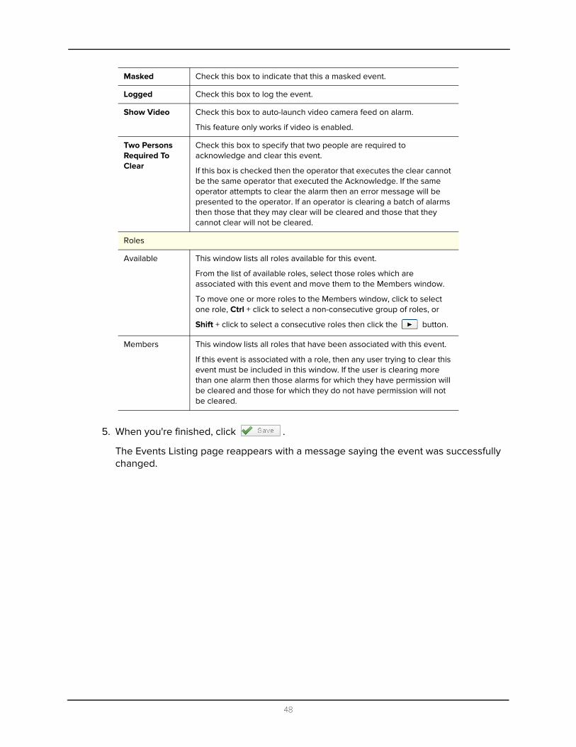
5. When you're finished, click .
The Events Listing page reappears with a message saying the event was successfully changed.
Masked Check this box to indicate that this a masked event.
Logged Check this box to log the event.
Show Video Check this box to auto-launch video camera feed on alarm.
This feature only works if video is enabled.
Two Persons Required To Clear
Check this box to specify that two people are required to acknowledge and clear this event.
If this box is checked then the operator that executes the clear cannot be the same operator that executed the Acknowledge. If the same operator attempts to clear the alarm then an error message will be presented to the operator. If an operator is clearing a batch of alarms then those that they may clear will be cleared and those that they cannot clear will not be cleared.
Roles
Available This window lists all roles available for this event.
From the list of available roles, select those roles which are associated with this event and move them to the Members window.
To move one or more roles to the Members window, click to select one role, Ctrl + click to select a non-consecutive group of roles, or
Shift + click to select a consecutive roles then click the button.
Members This window lists all roles that have been associated with this event.
If this event is associated with a role, then any user trying to clear this event must be included in this window. If the user is clearing more than one alarm then those alarms for which they have permission will be cleared and those for which they do not have permission will not be cleared.
48

12
RolesRoles limit or regulate the number of tasks that a specific user can perform within the Access Control Manager system. That is, use the Roles feature to associate a user with one or more application tasks. If a user tries to perform a task, such as generating reports, for which their role does not qualify them, the feature is not available to them.To access this feature:
1. From the icon task bar on the home page, click the Roles option.
The Roles main screen appears with the Roles Listing page uppermost like this example:
2. From the Roles Listing Page, click the button.
The Role Add page appears like this example:
3. Enter information about the role as required.
The fields on this page include:
Name Identifies the name of the role.
Parent From the drop-down list, select a role that is the parent to this role. If this is the parent role, leave this field blank. Only those roles previously defined for this system appear in this list.
Start Date Specify the date on which this role takes effect.
Enter MM/DD/YYYY or click in the field to open a pop-up calendar to select the date on which this role begins.
Stop Date Specify the date on which this role becomes inoperative.
Enter MM/DD/YYYY or click in the field to open a pop-up calendar to select the date on which this role ends.
49
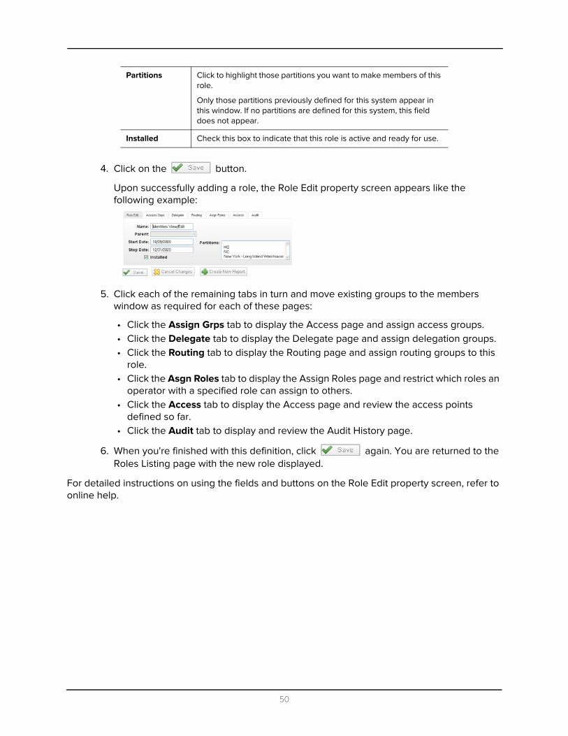
4. Click on the button.
Upon successfully adding a role, the Role Edit property screen appears like the following example:
5. Click each of the remaining tabs in turn and move existing groups to the members window as required for each of these pages:
• Click the Assign Grps tab to display the Access page and assign access groups.• Click the Delegate tab to display the Delegate page and assign delegation groups.• Click the Routing tab to display the Routing page and assign routing groups to this
role.• Click the Asgn Roles tab to display the Assign Roles page and restrict which roles an
operator with a specified role can assign to others.• Click the Access tab to display the Access page and review the access points
defined so far.• Click the Audit tab to display and review the Audit History page.
6. When you're finished with this definition, click again. You are returned to the Roles Listing page with the new role displayed.
For detailed instructions on using the fields and buttons on the Role Edit property screen, refer to online help.
Partitions Click to highlight those partitions you want to make members of this role.
Only those partitions previously defined for this system appear in this window. If no partitions are defined for this system, this field does not appear.
Installed Check this box to indicate that this role is active and ready for use.
50
13
Access GroupsBefore creating a role, we recommend that you define your required access groups. Access Groups combine a schedule (time) with doors within the system. Access Groups define the doors and times that can be accessed by a specified role.To add one or more access groups:
1. From the icon task bar on the home page, click Roles.
The Roles Listing page appears.
2. From the sub-options bar, click Access Groups.
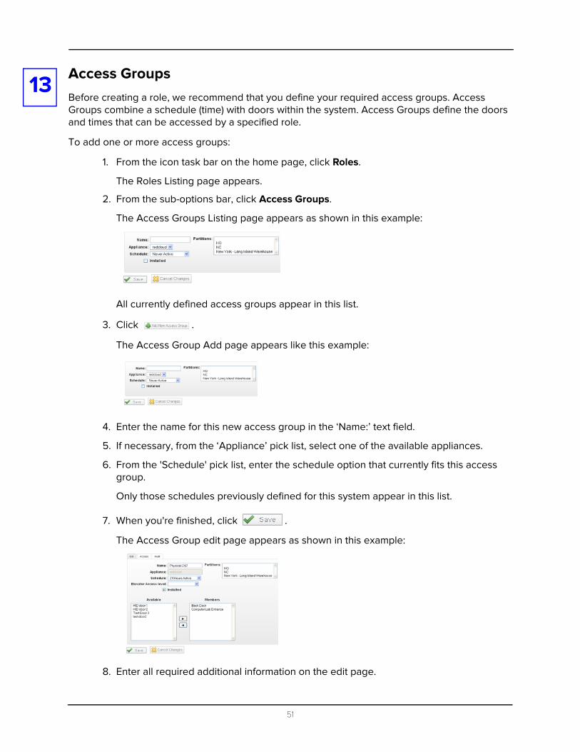
The Access Groups Listing page appears as shown in this example:
All currently defined access groups appear in this list.
3. Click .
The Access Group Add page appears like this example:
4. Enter the name for this new access group in the ‘Name:’ text field.
5. If necessary, from the ‘Appliance’ pick list, select one of the available appliances.
6. From the 'Schedule' pick list, enter the schedule option that currently fits this access group.
Only those schedules previously defined for this system appear in this list.
7. When you're finished, click .
The Access Group edit page appears as shown in this example:
8. Enter all required additional information on the edit page.
51
This includes adding doors from the ‘Available’ window to the ‘Members’ window by
selecting the selected door, then click the icon.
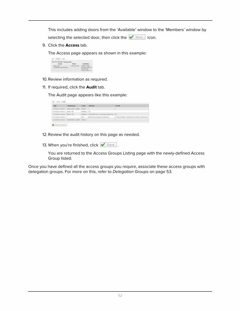
9. Click the Access tab.
The Access page appears as shown in this example:
10. Review information as required.
11. If required, click the Audit tab.
The Audit page appears like this example:
12. Review the audit history on this page as needed.
13. When you're finished, click .
You are returned to the Access Groups Listing page with the newly-defined Access Group listed.
Once you have defined all the access groups you require, associate these access groups with delegation groups. For more on this, refer to Delegation Groups on page 53.
52

14
Delegation GroupsDelegation (permissions) authorizes certain persons or groups of persons within the Access Control Manager database to perform predefined functions. In essence, this means that delegation groups are associations of identities with assigned Access Control Manager features.Before creating a role it is recommended that you determine the required delegations or permissions for that role.
To add one or more delegation groups:
1. From the icon task bar on the home screen, click the Roles option.
The Roles main screen appears.
2. From the available sub-options, click Delegation.
The Delegation Groups Listing page appears like this example:
3. From the Delegation Groups Listing page, click .
The Delegation Group Add page appears like this example:
4. Enter the name of this delegation group.
5. If required, specify one or more partitions for this group.
If no partitions are required, go to Step 6.
6. Click .
53

The Delegation Groups Edit page appears like this example:
7. Define this group by adding features in this manner:
a. In the ‘Available’ window, click to select a single function, click + Ctrl selects multiple non-sequential functions, or click + Shift to select sequential functions.
If there are too many functions, use the Search section to enter a term that filters the entries displayed in the 'Available' window then click to display the resulting list.
b. With the functions highlighted in the Available window, click the button. The selected functions are transferred to the Members window.
c. To move functions from the Members window back to the Available window, select the functions in the same manner, then click the button. The selected functions are returned to the Available window.
8. When you're finished, click .
You are returned to the Delegation Groups Listing page with a message indicating that the group has been added successfully.
The new Delegation group appears in the list.
Once you have defined a delegation group, you can associate people or groups of people with it by adding the delegation group to one or more roles. Once a role that includes this group is created, you can then associate people or groups of people with this delegation group simply by assigning the defined role to that person through the Identities feature.
For more on this, refer to Roles on page 49.
Move available features to the ‘Members’ window as required
54
15
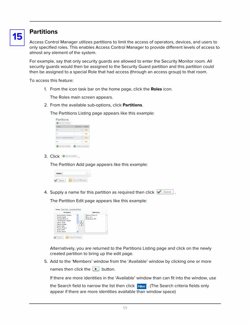
PartitionsAccess Control Manager utilizes partitions to limit the access of operators, devices, and users to only specified roles. This enables Access Control Manager to provide different levels of access to almost any element of the system.For example, say that only security guards are allowed to enter the Security Monitor room. All security guards would then be assigned to the Security Guard partition and this partition could then be assigned to a special Role that had access (through an access group) to that room.
To access this feature:
1. From the icon task bar on the home page, click the Roles icon.
The Roles main screen appears.
2. From the available sub-options, click Partitions.
The Partitions Listing page appears like this example:
3. Click .
The Partition Add page appears like this example:
4. Supply a name for this partition as required then click .
The Partition Edit page appears like this example:
Alternatively, you are returned to the Partitions Listing page and click on the newly created partition to bring up the edit page.
5. Add to the ‘Members’ window from the ‘Available’ window by clicking one or more
names then click the button.
If there are more identities in the ‘Available’ window than can fit into the window, use
the Search field to narrow the list then click . (The Search criteria fields only appear if there are more identities available than window space)
55

6. When, you're finished, click again.
You are returned to the Partitions Listing page with the newly-defined partition on the list.
For more on this, refer to Roles on page 49.
56
16
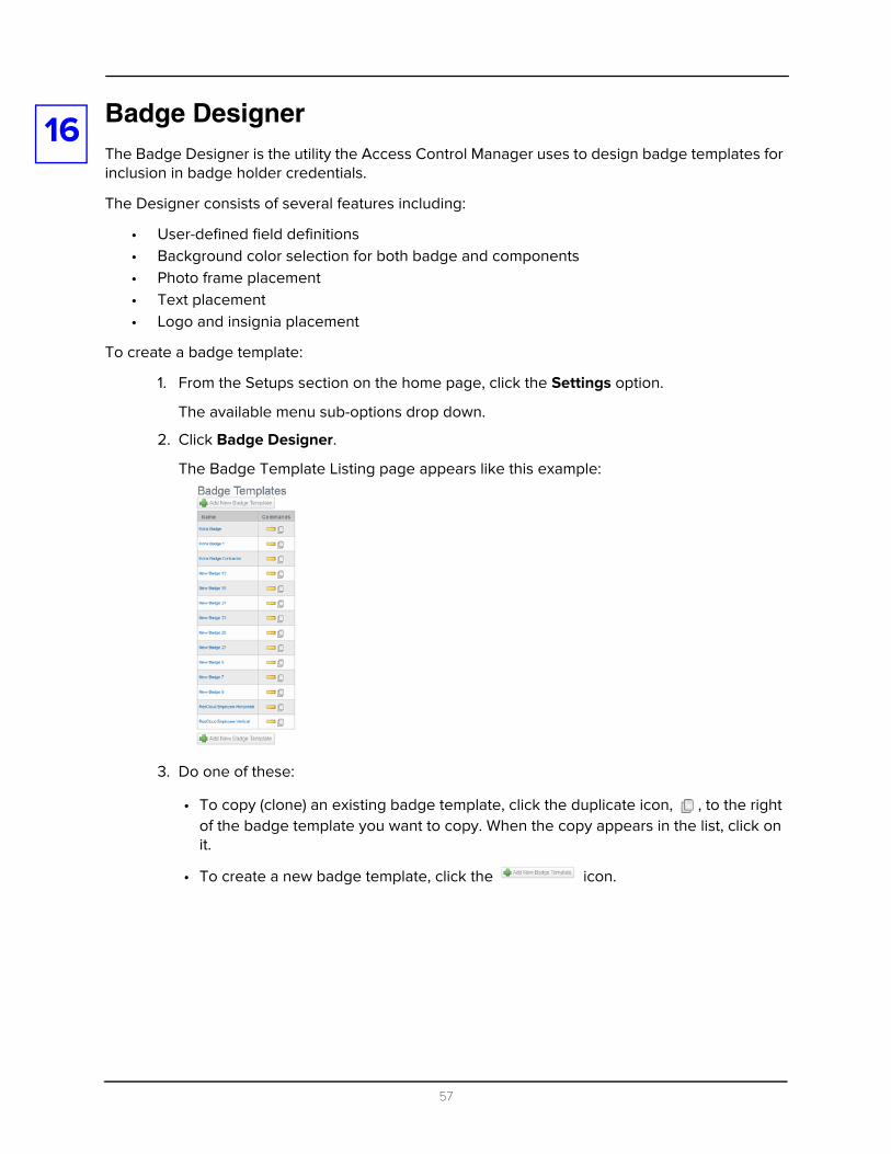
Badge DesignerThe Badge Designer is the utility the Access Control Manager uses to design badge templates for inclusion in badge holder credentials.The Designer consists of several features including:
• User-defined field definitions• Background color selection for both badge and components• Photo frame placement• Text placement• Logo and insignia placement
To create a badge template:
1. From the Setups section on the home page, click the Settings option.
The available menu sub-options drop down.
2. Click Badge Designer.
The Badge Template Listing page appears like this example:
3. Do one of these:
• To copy (clone) an existing badge template, click the duplicate icon, , to the right of the badge template you want to copy. When the copy appears in the list, click on it.
• To create a new badge template, click the icon.
57

The designated badge template add page appears like this example:
4. Enter a name for this badge template in the ‘Name’ field.
5. Specify the size of the badge you require in the ‘Size’ field.
6. If required, select one or more partitions this badge template is a member of.
Only those partitions previously defined for this system appear in this window.
7. Design the badge like this:
• To create a background, click the ‘BG Color’ field and specify a background for this badge template. For more on this, refer to Changing a Background on page 59.
• To add one or more pictures, click the button and add pictures to this badge template. For more on this, refer to Adding Pictures on page 60.
• To place database fields, click the button and place the required database fields on this template. For more on this, refer to Adding Database Fields on page 61.
• To place text, click the button and add text on this template. For more on this, refer to Adding Text on page 62.
• To add graphics, click the button and place one or more graphics on this template. For more on this, refer to Adding Graphics on page 64.
Make sure to save by clicking after each of these operations or your changes will not be reflected on the canvas. The badge preview pane appears below the canvas.
8. If you need to delete an existing element from the badge template, click the button to the right of the selected object.
The deleted object remains on the canvas until you click .
9. If you need to design a back side for this template, click and repeat Step 6 to design the obverse side of this badge.
The back side will only print if you have a dual-side or duplex badge printer connected to this appliance.
58
10. When you're finished customizing this template, click once again.
A message appears indicating the success of the badge template creation.
11. Click and you are returned to the Badge Template Listing page with the newly defined badge template in the list.
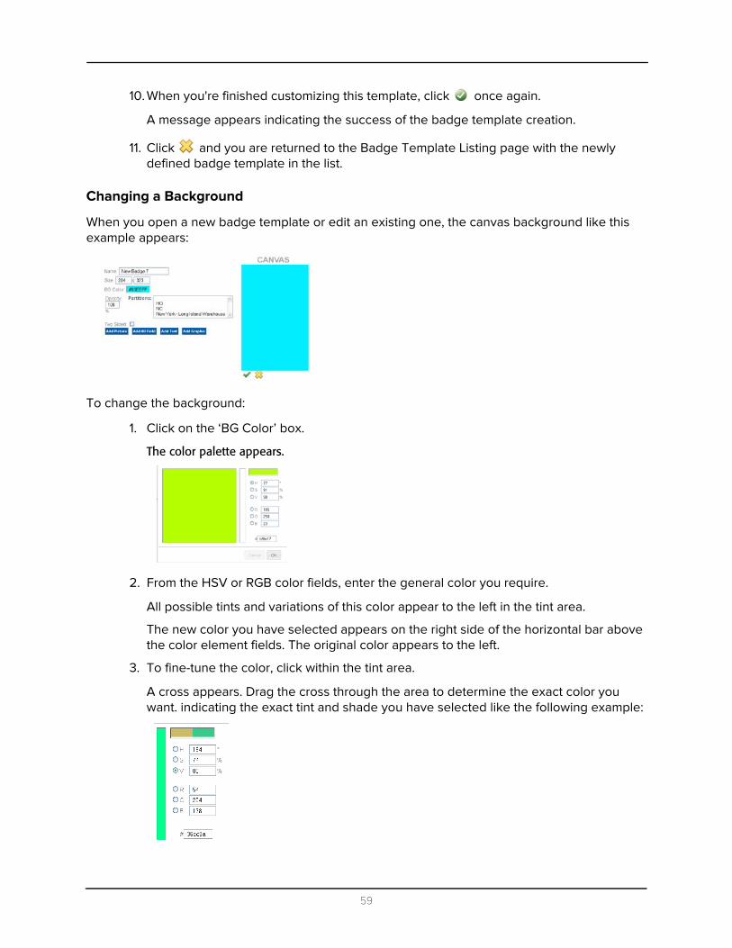
Changing a Background
When you open a new badge template or edit an existing one, the canvas background like this example appears:
To change the background:
1. Click on the ‘BG Color’ box.
The color palette appears.
2. From the HSV or RGB color fields, enter the general color you require.
All possible tints and variations of this color appear to the left in the tint area.
The new color you have selected appears on the right side of the horizontal bar above the color element fields. The original color appears to the left.
3. To fine-tune the color, click within the tint area.
A cross appears. Drag the cross through the area to determine the exact color you want. indicating the exact tint and shade you have selected like the following example:
59

The number in the Color field changes to reflect your choice.
4. If required, slide up or down the vertical slide bar to change the color still further.
5. When you're finished with this palette, click OK.
6. Click the icon to impose the new color on the canvas or other element.
Adding Pictures
When you click , an element entitled PHOTO is added to the Attributes list, like the following example:
Photo Toggle this word to hide or reveal the fields.
Click this icon to delete the photo data and hide the fields associated with this for this object.
The picture object remains on the canvas until you click the button.
Layer Order Enter the number indicating the layer this graphic occupies on the badge, where 1 is the bottom layer, 2 is the next higher layer, and so on.
Layer ordering is useful when two or more objects are superimposed on each other.
Location Enter values to move the photo frame around on the canvas. As you change values, the photo rectangle will change positions on the work board.
Dimensions Enter values to resize the photo frame, where the first value is the width and the second value is the height. As you change the values, the size of the rectangle will change to reflect it.
Rotation Enter the value, in degrees, to rotate this object. The higher the number of degrees the farther clockwise the object will be rotated. Default is 0 degrees.
Maintain Aspect
Check this box to maintain the aspect ratio of the picture that appears in this frame. If this feature is left unchecked, the picture will simply fill the available frame space and skew the photo to match.
60

NOTE: None of the values entered here are reflected on the canvas until you have saved the
screen by clicking . Once saved, the preview pane displays the relevant image.
Adding Database Fields
Database fields are essentially placeholders for information that is supplied by the Identities database. These fields are populated by data supplied for the specific badge holder. For example, if you place a database field on this badge template that calls the Last Name data field, a badge issued to William Smith assigned this badge template will automatically populate this field with the value 'Smith'. The same holds true for birth date, badge expiration, eye color, and many others.
When you click the button, a Data Field attribute is added to the attributes list, like this example:
The fields on this page are described below:
Data Field Select from a drop-down list the data field you want to include on this template. Only those data fields previously defined for this system appear in this list, including all user-defined data fields. When you click this field title, the attributes below appear. Toggle Data Field to hide or reveal current fields.
Click this icon to delete the current data and hide the fields associated with this for this object.
The picture object remains on the canvas until you click the button.
Layer Order Enter the number indicating the layer this data field occupies on the badge, where 1 is the bottom layer, 2 is the next higher layer, and so on.
Layer ordering is useful when two or more objects are superimposed on each other.
Location Enter values to move the data field around on the work board. As you change values, the Data rectangle will change positions on the work board.
Dimensions Enter values to resize the data field rectangle, where the first value is the width and the second value is the height. As you change the values, the size of the rectangle will change to reflect it.
Rotation Enter the value, in degrees, to rotate this database object. The higher the number of degrees the farther clockwise the object will be rotated. Default is 0 degrees.
61

When you select a Data Field option, the placeholder for that option appears on the canvas as shown in the following example.
Use your mouse to drag this placeholder to another location on the canvas, or use the Location options in the attributes list to relocate it.
NOTE: None of the values entered here are reflected on the canvas until you have saved the screen by clicking . The Preview pane appears with the new data field reflected.
Adding Text
BG Color Enter the color you require for the background of this DB field. When you click on this field, a color palette appears. Select the general color, then fine tune it as required. Each change you make to the color is reflected on the work space.
Font Select from the drop-down list the font you want used for the text in this data field.
Font size Select from the drop-down list the font size you want used for the text in this data field.
Alignment Select the alignment you require for this data field.
Text Color Enter the color you require for the text used in this DB field. When you click on this field, a color palette appears. Select the general color, then fine tune it with the slider as required. Each change you make to the text color is reflected on the work space.
Opacity In the text box, enter the percentage of opacity you want for the selected text color.
The lower the number, the fainter the color that appears.
You can drag this placeholder to another location...
... or use the ‘Location’ property fields to reposition it
The result appears in the Preview pane
62

When you click the button, a Text field appears, like this example:
Notice that a text placeholder appears on the canvas. Use your mouse to drag this text placeholder to the required position on the canvas, or alternatively fine-tune the position using the Location field.
The fields in this section are described below:
Text Enter the text you want to appear on this template. Toggle Text to hide or reveal current fields.
Click this icon to delete and hide the current text object fields.
The text object remains on the canvas until you click the button.
Layer Order Enter the number indicating the layer this text occupies on the badge, where 1 is the bottom layer, 2 is the next higher layer, and so on.
Layer ordering is useful when two or more objects are superimposed on each other.
Location Enter values to move the text field around on the work board. As you change values, the text rectangle will change positions on the work board.
Dimensions Enter values to resize the text field rectangle, where the first value is the width and the second value is the height. As you change the values, the size of the rectangle will change to reflect it.
Rotation Enter the value, in degrees, to rotate this object. The higher the number of degrees the farther clockwise the object will be rotated. Default is 0 degrees.
BG Color Enter the color you require for the background of this text field. When you click on this field, a color palette appears. Select the general color, then fine tune it as required. Each change you make to the text background color is reflected on the canvas only after you have saved it.
Font Select from the drop-down list the font you want used for the text in this field.
Font size Select from the drop-down list the font size you want used for the text in this field.
Alignment Select the alignment you require for this field.
Text field and associated properties
You can drag this placeholder to another location...
63

NOTE: None of the values entered here are reflected on the canvas until you have saved the screen by clicking . The Preview pane appears with the new data field reflected.
Adding Graphics
When you click , a graphic property appears under Attributes like the following example:
Notice that a graphic placeholder appears on the canvas. Use you mouse to drag this placeholder to another location on the canvas, or use the Location options in the attributes list to relocate it.
The fields in the attributes list include:
Text Color Enter the color you require for the text used in this field. When you click on this field, a color palette appears. Select the general color, then fine tune it as required. Each change you make to the text color is reflected on the canvas only after you have saved it.
Opacity In the text box, enter the percentage of opacity you want for the selected text color.
The lower the number, the fainter the color that appears.
Click this icon to delete the current graphic data and hide the fields associated with this for this object.
The picture object remains on the canvas until you click the button.
Image Either enter the path and file name for the image you want to appear here, or click the
button to locate and identify the image file you want to use. The image you need must be copied to an accessible directory before you can browse for it.
Location Enter values to move the image around on the work board. As you change values, the placeholder will change positions on the canvas. You can also use these fields to fine tune the location of the graphic on this badge template.
Dimensions Enter values to resize the graphic rectangle, where the first value is the width and the second value is the height. As you change the values, the size of the rectangle will change to reflect it.
Rotation Enter the value, in degrees, to rotate this object. The higher the number of degrees the farther clockwise the object will be rotated. Default is 0 degrees.
64

NOTE: None of the values entered here are reflected on the canvas until you have saved the
screen by clicking . The Preview pane appears with the new data field reflected.
Badge Camera Configuration
The Access Control Manager enables the qualified operator to capture photos from a networked camera. Most cameras are supported by this application as long as the output of the device is digital and supports the jpg image format.
NOTE: Before the Access Control Manager can use the device, it must first be connected to a LAN that is accessible to the Access Control Manager appliance.
To connect and configure a camera for capturing photos:
1. Using the instructions for your network-compatible camera, connect the camera to the network and configure it.
2. At the User Links section of the home page, click the My Account link.
The My Account Profile page appears like this example:
3. At the 'Badge Camera' field, select from the drop-down list the device you plan to use to capture pictures.
Only those devices previously defined for this system appear in this drop-down list.
4. When you're finished, click .
The selected camera is now the default capture device.
To further define the use of this camera within the Access Control Manager environment:
1. At the Setup links section of the home page, mouse-over Settings.
A pull-down option list appears.
2. From the available sub-options, select External Systems.
Maintain Aspect
Click to check this box designating that resizing this graphic will not change the aspect ratio of the image. Using this feature you can avoid distorting the image.
Select the camera to use
65

The IP Camera Listing page appears like this example.
3. Select one of the currently available device types:
• For an IP-based camera, go to step 4.• For an Exacq server, click the Exacq tab and the Exacq Servers listing page appears.• For a Pelco server, click the Pelco tab and the Pelco Server listing page appears.• For a LifeSafety power supply, click the LifeSafety tab and the LifeSafety power
listing page appears.• For an Avigilon server, click the Avigilon tab and the Avigilon server listing page
appears.• For a Salient server, click the Salient tab and the Salient listing page appears.• For a Milestone server, click the Milestone tab and the Milestone listing page
appears.4. From the appropriate listing page, click the appropriate add button. For example, at the
IP-Based camera page, you would click .
The appropriate Add page appears like this example:
5. Fill out the fields on the page as required.
This page includes these fields and buttons:
IP-Based Camera
Name Enter the name of this device. Pick a name that will help identify the camera.
Type From the pick list, select the type of image device this is. You can select from:
Web Camera - This is a network-attached camera.RTSP - The Real Time Streaming Protocol is a network control protocol designed for use in entertainment and communications systems.
Device IP Enter the IP address for this device.
Still URL Enter the URL or web address, if required, of this camera's web-based application showing the still picture this camera is currently framing.
66
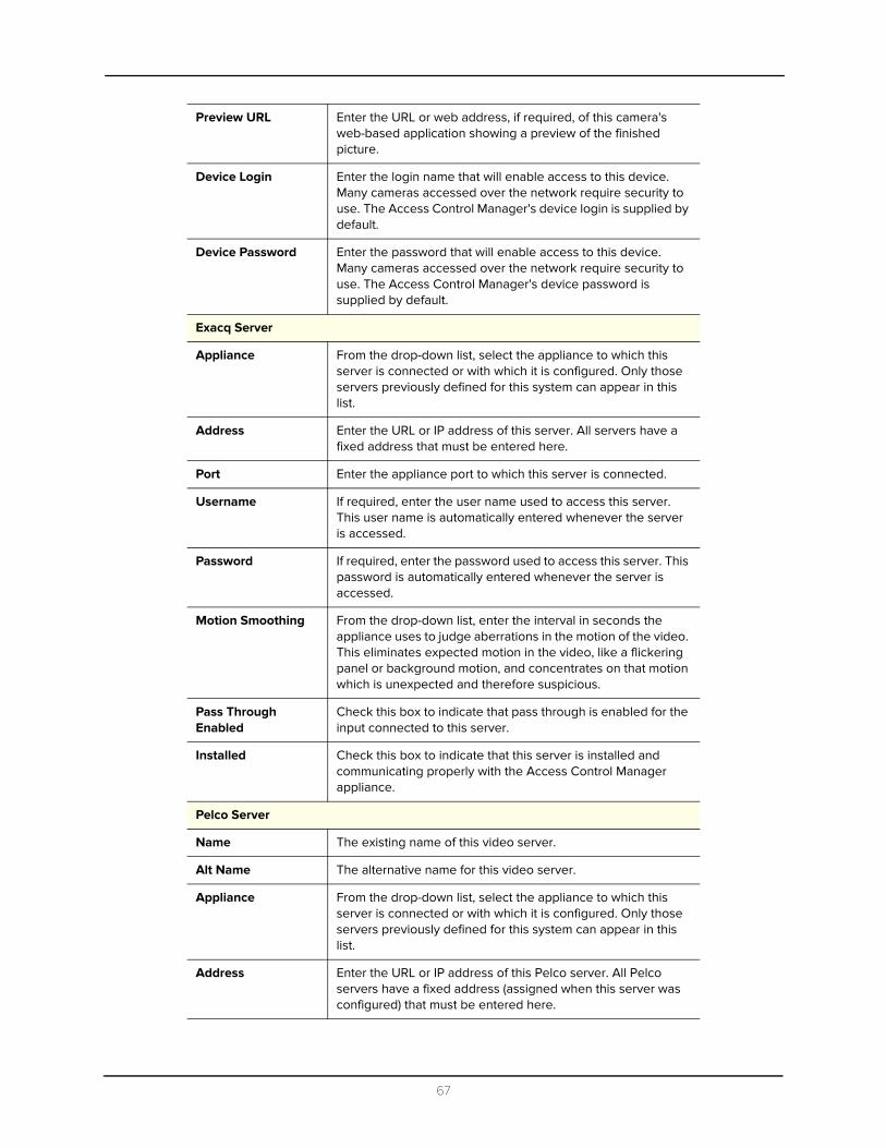
Preview URL Enter the URL or web address, if required, of this camera's web-based application showing a preview of the finished picture.
Device Login Enter the login name that will enable access to this device. Many cameras accessed over the network require security to use. The Access Control Manager's device login is supplied by default.
Device Password Enter the password that will enable access to this device. Many cameras accessed over the network require security to use. The Access Control Manager's device password is supplied by default.
Exacq Server
Appliance From the drop-down list, select the appliance to which this server is connected or with which it is configured. Only those servers previously defined for this system can appear in this list.
Address Enter the URL or IP address of this server. All servers have a fixed address that must be entered here.
Port Enter the appliance port to which this server is connected.
Username If required, enter the user name used to access this server. This user name is automatically entered whenever the server is accessed.
Password If required, enter the password used to access this server. This password is automatically entered whenever the server is accessed.
Motion Smoothing From the drop-down list, enter the interval in seconds the appliance uses to judge aberrations in the motion of the video. This eliminates expected motion in the video, like a flickering panel or background motion, and concentrates on that motion which is unexpected and therefore suspicious.
Pass Through Enabled
Check this box to indicate that pass through is enabled for the input connected to this server.
Installed Check this box to indicate that this server is installed and communicating properly with the Access Control Manager appliance.
Pelco Server
Name The existing name of this video server.
Alt Name The alternative name for this video server.
Appliance From the drop-down list, select the appliance to which this server is connected or with which it is configured. Only those servers previously defined for this system can appear in this list.
Address Enter the URL or IP address of this Pelco server. All Pelco servers have a fixed address (assigned when this server was configured) that must be entered here.
67
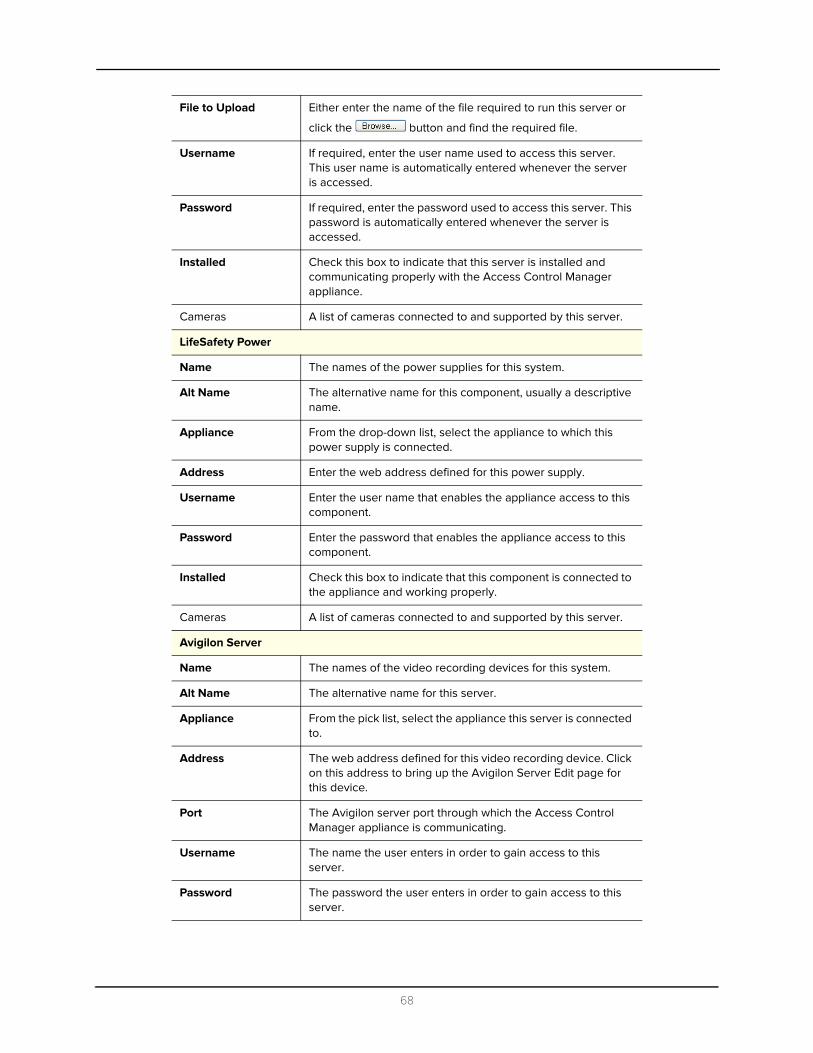
File to Upload Either enter the name of the file required to run this server or
click the button and find the required file.
Username If required, enter the user name used to access this server. This user name is automatically entered whenever the server is accessed.
Password If required, enter the password used to access this server. This password is automatically entered whenever the server is accessed.
Installed Check this box to indicate that this server is installed and communicating properly with the Access Control Manager appliance.
Cameras A list of cameras connected to and supported by this server.
LifeSafety Power
Name The names of the power supplies for this system.
Alt Name The alternative name for this component, usually a descriptive name.
Appliance From the drop-down list, select the appliance to which this power supply is connected.
Address Enter the web address defined for this power supply.
Username Enter the user name that enables the appliance access to this component.
Password Enter the password that enables the appliance access to this component.
Installed Check this box to indicate that this component is connected to the appliance and working properly.
Cameras A list of cameras connected to and supported by this server.
Avigilon Server
Name The names of the video recording devices for this system.
Alt Name The alternative name for this server.
Appliance From the pick list, select the appliance this server is connected to.
Address The web address defined for this video recording device. Click on this address to bring up the Avigilon Server Edit page for this device.
Port The Avigilon server port through which the Access Control Manager appliance is communicating.
Username The name the user enters in order to gain access to this server.
Password The password the user enters in order to gain access to this server.
68

VidProxyUrl The URL used as a translator between the appliance and the server.
VidProxyImageUrl The URL used to store the video captured by the Avigilon server.
Installed Check this box to indicate that this server is connected and working properly.
Cameras The name and UUID of each camera this server accesses, their current status, whether they are PTZ or not, and their zoom capability.
Salient Server
Name The names of the video server for this system.
Alt Name The alternative name for this server.
Appliance From the drop-down list, select the appliance to which this server is connected or with which it is configured. Only those servers previously defined for this system can appear in this list.
Hostname Enter the network name, URL, or IP address of this Salient server. All Salient servers have a fixed address (assigned when this server was configured) that must be entered here.
Port Enter the port number to which this server is connected on the appliance.
WebServicePort Enter the port number that this server uses to communicate with its web service.
Username If required, enter the user name used to access this server.
This user name is automatically entered whenever the server is accessed.
Password If required, enter the password used to access this server. This password is automatically entered whenever the server is accessed.
VidProxyUrl The URL used as a translator between the appliance and the server.
Installed Check this box to indicate that this server is connected and working properly.
Milestone Server
Name The names of the video recording devices for this system.
Alt Name The alternative name for this server.
Appliance From the pick list, select the appliance this server is connected to.
Address The web address defined for this video recording device. Click on this address to bring up the Milestone Server Edit page for this device.
Port Enter the Milestone server port through which the Access Control Manager appliance is communicating.
69

6. Once you’ve selected the field values you need, click to save these changes.
The new device appears on the listing page.
Username The name the user enters in order to gain access to this server.
Password The password the user enters in order to gain access to this server.
VidProxyUrl The URL used as a translator between the appliance and the server.
VidProxyImageUrl The URL used to store the video captured by the Milestone server.
Installed Check this box to indicate that this server is connected and working properly.
70
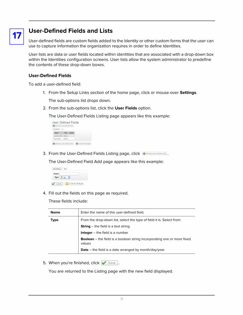
17
User-Defined Fields and ListsUser-defined fields are custom fields added to the Identity or other custom forms that the user can use to capture information the organization requires in order to define Identities.User lists are data or user fields located within identities that are associated with a drop-down box within the Identities configuration screens. User lists allow the system administrator to predefine the contents of these drop-down boxes.
User-Defined Fields
To add a user-defined field:
1. From the Setup Links section of the home page, click or mouse-over Settings.
The sub-options list drops down.
2. From the sub-options list, click the User Fields option.
The User-Defined Fields Listing page appears like this example:
3. From the User-Defined Fields Listing page, click .
The User-Defined Field Add page appears like this example:
4. Fill out the fields on this page as required.
These fields include:
5. When you're finished, click .
You are returned to the Listing page with the new field displayed.
Name Enter the name of this user-defined field.
Type From the drop-down list, select the type of field it is. Select from:
String – the field is a text string
Integer – the field is a number
Boolean – the field is a boolean string incorporating one or more fixed values
Date – the field is a date arranged by month/day/year
71
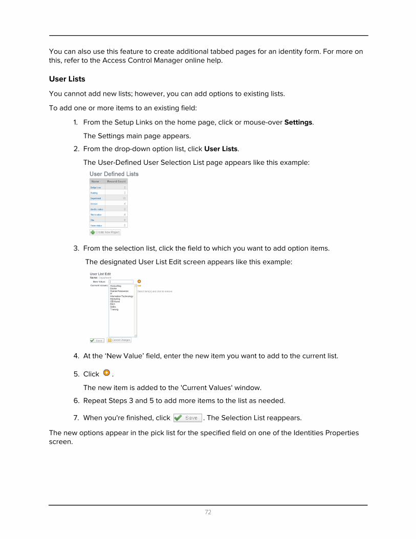
You can also use this feature to create additional tabbed pages for an identity form. For more on this, refer to the Access Control Manager online help.
User Lists
You cannot add new lists; however, you can add options to existing lists.
To add one or more items to an existing field:
1. From the Setup Links on the home page, click or mouse-over Settings.
The Settings main page appears.
2. From the drop-down option list, click User Lists.
The User-Defined User Selection List page appears like this example:
3. From the selection list, click the field to which you want to add option items.
The designated User List Edit screen appears like this example:
4. At the ‘New Value’ field, enter the new item you want to add to the current list.
5. Click .
The new item is added to the 'Current Values' window.
6. Repeat Steps 3 and 5 to add more items to the list as needed.
7. When you're finished, click . The Selection List reappears.
The new options appear in the pick list for the specified field on one of the Identities Properties screen.
72
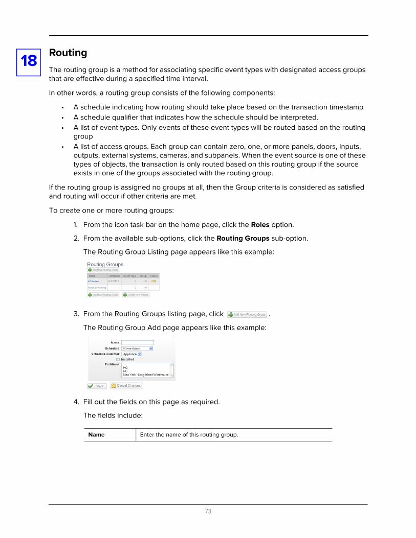
18
RoutingThe routing group is a method for associating specific event types with designated access groups that are effective during a specified time interval.In other words, a routing group consists of the following components:
• A schedule indicating how routing should take place based on the transaction timestamp• A schedule qualifier that indicates how the schedule should be interpreted.• A list of event types. Only events of these event types will be routed based on the routing
group• A list of access groups. Each group can contain zero, one, or more panels, doors, inputs,
outputs, external systems, cameras, and subpanels. When the event source is one of these types of objects, the transaction is only routed based on this routing group if the source exists in one of the groups associated with the routing group.
If the routing group is assigned no groups at all, then the Group criteria is considered as satisfied and routing will occur if other criteria are met.
To create one or more routing groups:
1. From the icon task bar on the home page, click the Roles option.
2. From the available sub-options, click the Routing Groups sub-option.
The Routing Group Listing page appears like this example:
3. From the Routing Groups listing page, click .
The Routing Group Add page appears like this example:
4. Fill out the fields on this page as required.
The fields include:
Name Enter the name of this routing group.
73
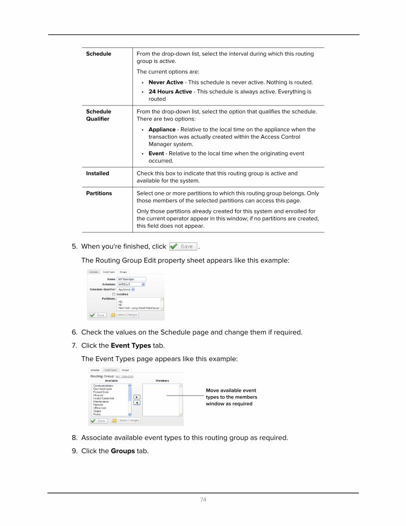
5. When you're finished, click .
The Routing Group Edit property sheet appears like this example:
6. Check the values on the Schedule page and change them if required.
7. Click the Event Types tab.
The Event Types page appears like this example:
8. Associate available event types to this routing group as required.
9. Click the Groups tab.
Schedule From the drop-down list, select the interval during which this routing group is active.
The current options are:
• Never Active - This schedule is never active. Nothing is routed.
• 24 Hours Active - This schedule is always active. Everything is routed
Schedule Qualifier
From the drop-down list, select the option that qualifies the schedule. There are two options:
• Appliance - Relative to the local time on the appliance when the transaction was actually created within the Access Control Manager system.
• Event - Relative to the local time when the originating event occurred.
Installed Check this box to indicate that this routing group is active and available for the system.
Partitions Select one or more partitions to which this routing group belongs. Only those members of the selected partitions can access this page.
Only those partitions already created for this system and enrolled for the current operator appear in this window; if no partitions are created, this field does not appear.
Move available event types to the members window as required
74

The Groups page appears like this example:
10. Associate available access groups with this routing group as required.
11. When you're finished, click .
You are returned to the Routing Groups Listing page.
Move available access groups to the members window as required
75
19
CollaborationCollaboration provides the ability to exchange data between the Access Control Manager appliance application and a large number of other database types.NOTE: This is normally a second-level feature and need not be performed initially. For more on this, refer to the Access Control Manager online help and the Collaboration Administration Summary.
76

20
IdentitiesThe Identities feature is used to enroll employees and all other workers and service personnel who require access to a facility or location maintained and overseen by the Access Control Manager system.Adding Identities
To add a new Identity:
1. From the home page icon task bar, click Identities.
The Identities Listing page appears like this example:
2. Click the button.
The Identity Profile dialog box appears like this example:
Only those identity profiles already defined for this system appear in this list. For more on defining profiles, refer to Identity Profiles on page 87.
3. Do one of these:
• If you have defined one or more profiles for this system, select the profile you want from the 'Identity Profile' pick list then click OK.
• If no profiles have been defined for this system or you want to bypass assignment of profile values for this identity, click Cancel.
77
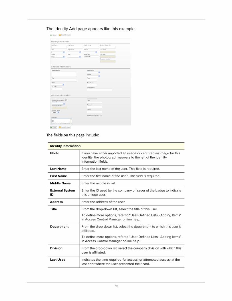
The Identity Add page appears like this example:
The fields on this page include:
Identity Information
Photo If you have either imported an image or captured an image for this identity, the photograph appears to the left of the Identity Information fields.
Last Name Enter the last name of the user. This field is required.
First Name Enter the first name of the user. This field is required.
Middle Name Enter the middle initial.
External System ID
Enter the ID used by the company or issuer of the badge to indicate this unique user.
Address Enter the address of the user.
Title From the drop-down list, select the title of this user.
To define more options, refer to “User-Defined Lists - Adding Items” in Access Control Manager online help.
Department From the drop-down list, select the department to which this user is affiliated.
To define more options, refer to “User-Defined Lists - Adding Items” in Access Control Manager online help.
Division From the drop-down list, select the company division with which this user is affiliated.
Last Used Indicates the time required for access (or attempted access) at the last door where the user presented their card.
78

Status Select the option from the pick list that describes the current status of this new user.
Active - this is a current user. Expired - this user's access has expired.
Lost - this user's access card/badge is reported lost.
Stolen - this user's access card/badge is reported stolen.
This field is required.
Type From the drop-down list, select the type of identity this is. Default values include Employee, Contractor, and Visitor.
To define more options, refer to “User-Defined Lists - Adding Items” in Access Control Manager online help.
Issue Date Specify the date this identity was issued. Click the field to bring up and use the calendar.
Last Door Indicates the last door this identity accessed.
Sequence Number
Indicates the sequence number assigned by the system to this individual. The initial count of this number is specified in the System Settings.
Address Information
Street Address Enter the address of the user.
City Enter the city where this user lives.
State Enter the state where the user lives.
Zip Code Enter the zip code where the user lives.
Site Location From the drop-down list, select the location where this user works.
To define more options, refer to “User-Defined Lists - Adding Items” in Access Control Manager online help.
Building From the drop-down list, select the building where this user works.
To define more options, refer to “User-Defined Lists - Adding Items” in Access Control Manager online help.
Phone Enter the phone number this user has. This can be either cell phone or home phone.
Work Phone Enter the phone number where this user works.
Email Address Enter the user's email address.
Account Information
Remote Authentication?
Check this box to indicate that this identity can access this system remotely. The password and confirm fields disappear.
Remote authenticate is achieved by defining a default domain and server from the Remote Authentication page.
79
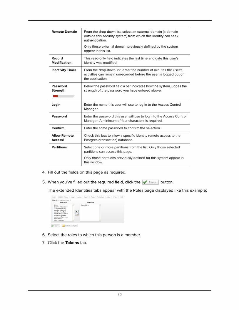
4. Fill out the fields on this page as required.
5. When you've filled out the required field, click the button.
The extended Identities tabs appear with the Roles page displayed like this example:
6. Select the roles to which this person is a member.
7. Click the Tokens tab.
Remote Domain From the drop-down list, select an external domain (a domain outside this security system) from which this identity can seek authentication.
Only those external domain previously defined by the system appear in this list.
Record Modification
This read-only field indicates the last time and date this user's identity was modified.
Inactivity Timer From the drop-down list, enter the number of minutes this user's activities can remain unrecorded before the user is logged out of the application.
Password Strength
Below the password field a bar indicates how the system judges the strength of the password you have entered above.
Login Enter the name this user will use to log in to the Access Control Manager.
Password Enter the password this user will use to log into the Access Control Manager. A minimum of four characters is required.
Confirm Enter the same password to confirm the selection.
Allow Remote Access?
Check this box to allow a specific identity remote access to the Postgres (transaction) database.
Partitions Select one or more partitions from the list. Only those selected partitions can access this page.
Only those partitions previously defined for this system appear in this window.
80

The Tokens page appears like this example:
The fields on this page include:
Embossed Number
Enter the number embossed on the card that will be issued to this user. This is only required if a physical card is being issued.
Internal Number Enter the actual number encoded on the ID card.
PIN Enter the number this card requires to be entered at a reader in order to grant access to this user or perform the function for which the token was created. This number is only required if a keypad entry is necessary.
Status From the pick list, select the current status option of the token assigned to this identity.
Issue Level From the pick list, select the issue level this token possesses. The range is 0 to 9 where 0 is no issue level and 9 is the highest possible issue level.
Click this button to download this token to all connected panels. This button only appears after the token has been saved.
Click this button to grant the person assigned this token one free pass through a door. This button only appears after the token has been saved.
APB Exempt Check this box to designate that this token is exempted from the use of anti-passback at doors or access points where APB is normally enforced. This is generally used for executive override.
Trace Check this box to enable tracing when this token is used.
Download Check this box to enable downloading of this token. This feature is checked and enabled by default.
Never Expire Check this box to indicate that this token never expires.
Extended door times
Check this box to indicate that this token can use extended door times. This is particularly useful for token holders with special needs.
Issue Date Click inside this field and use the calendar to specify the date when this token is issued.
Alternatively, enter the date using the keyboard.
Activate Date Click inside this field and use the calendar to specify the date when this token is activated.
Alternatively, enter the date using the keyboard.
81

8. Customize tokens for this identity as required.
9. Click the Groups tab.
The Groups page appears like this example:
10. Assign groups to this person as required.
11. Click the Access tab.
The Access page appears like this example:
12. Review the roles that this person can currently access and the doors that these roles support.
If necessary, you can return to the Roles page and redefine the roles this person is assigned.
13. Click the Capture tab.
The Capture page appears like this example:
Deactivate Date Click inside this field and use the calendar to specify the date when this token is deactivated.
Alternatively, enter the date using the keyboard.
Last Door Indicates the last door at which this token was used to gain access.
Last Time Indicates the last time this token was used to gain access.
Click this button to save the current settings.
Click this button to exit this page and return to the higher level screen.
82

If the capture device has been secured by a user name and password, this page will not appear until you have supplied the required values to the authentication prompt like this:
14. Supply the required user name and password then click OK and the Capture page should appear.
15. To capture a picture from this page using a previously attached and configured camera:
a. Click on the next to the identity that requires a photo.
The connected capture device takes a picture of the designated person and places it on the Capture page.
b. To create additional pictures, repeat Step a.
c. To view all captured pictures for this person, click on the person's name.
The Identities Edit screen appears.
d. Select the Capture tab to view the Identity Capture page.
e. Click to select the image you want to use for the person.
f. Click to save this image.
16. Click the Photos tab.
The Photos page appears like this example:
17. Click the button.
The screen expands to include two fields like this example:
18. At the 'Photo' text box, either enter a file name complete with path, or click the
button and, using the Choose File dialog box, navigate to the directory and file containing the image you want to upload.
If you need to remove this dialog box, click the button.
19. Click Open to confirm the choice.
20.If this is the primary photo to be used for this person, click to check the Primary box.
83
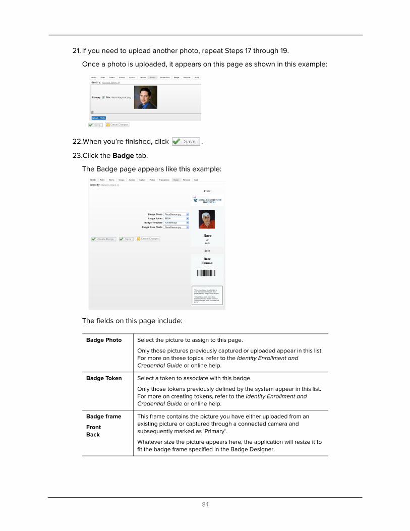
21. If you need to upload another photo, repeat Steps 17 through 19.
Once a photo is uploaded, it appears on this page as shown in this example:
22.When you’re finished, click .
23.Click the Badge tab.
The Badge page appears like this example:
The fields on this page include:
Badge Photo Select the picture to assign to this page.
Only those pictures previously captured or uploaded appear in this list. For more on these topics, refer to the Identity Enrollment and Credential Guide or online help.
Badge Token Select a token to associate with this badge.
Only those tokens previously defined by the system appear in this list. For more on creating tokens, refer to the Identity Enrollment and Credential Guide or online help.
Badge frame
FrontBack
This frame contains the picture you have either uploaded from an existing picture or captured through a connected camera and subsequently marked as 'Primary'.
Whatever size the picture appears here, the application will resize it to fit the badge frame specified in the Badge Designer.
84

24.Enter the required fields.
25.Click the Transactions tab.
The Transactions page appears like this example:
This page enables the qualified operator to review past alarms and events that this identification has caused. The information in this table is listed by these columns:
26.Review the transactions on this page, if required.
27.To print a badge, from the Badge page click the button.
Badge Template
Select an available badge template from the drop-down list.
Only those badge templates previously defined by the system appear in this list. For more on creating badge templates, refer to “Badge Designer” starting on page 57.
Badge Back Photo
Select an available picture to place on the back of this card.
Only those pictures previously captured or uploaded appear in this list. This field is not enabled unless the designated template allows both front and back design.
Click this button to print the badge to a designated badge printer.
Click this button once you've selected all of the groups you want to save your selections.
Click this button to ignore changes made during the present session and return to the previous page.
When The date and time when this event occurred.
Priority The importance of this event where 0 is least important and 99 is most important. Priority numbers are assigned through the 'Priority' text box on the Events Add page.
Event Name The name of the event. Names are specified in Events - Adding.
Source Name The name of the person causing the event. This name is assigned to the token that caused the event as specified in Identities - Adding.
Source Location
Displays the location where this event or alarm occurred.
Card No If this token was assigned to a card, this displays the card number.
Message This displays the message associated with the event. Messages are assigned through the Events Add page.
85
A badge for this person is printed to the designated badge printer.
28.If needed, click the Audit tab to display and review the Audit page.
29.When you're finished, click .
30.Click either the Identities > linked bread crumb above the page or click .
You are returned to the Identities Listing page.
Searching for Identities
To search for previously created identities, or all identities:
1. In the 'Last Name' text box, enter the last name of the person you are looking for.
If required, in the 'First Name' text box, enter the first name of the person you are looking for.
If required, in the 'Token' text box, enter the internal number of the identity you are seeking. In whichever field you type, the program will attempt to assist you by finishing your search term with an existing name or token, such as if you are placed a wildcard after your entry.
2. In the pull-down box to the right of these three boxes, select whether the values entered in the Last Name, First Name, and Token fields should be combined into a single search criteria (And) or used as separate search criteria (Or).
If the And value is selected, only those identities to fit all entered conditions will appear. If the Or condition is selected, each entered value is employed as a separate criteria.
For example, if you entered Smith in the 'Last Name' field and William in the 'First Name' field, selecting And as your condition instructs the application search engine to find only those identities in the database that are named William Smith. If you select the Or condition instead, all identities that have the last name of Smith or the first name of William are listed.
NOTE: At any point, you can clear values you have already entered and start over by clicking the .
3. Click .
The search engine processes the request and displays all people in the database who fit the entered information.
NOTE: For more on creating valid search terms, refer to the Access Control Manager online help or the Identity Enrollment and Credentialing Guide.
86
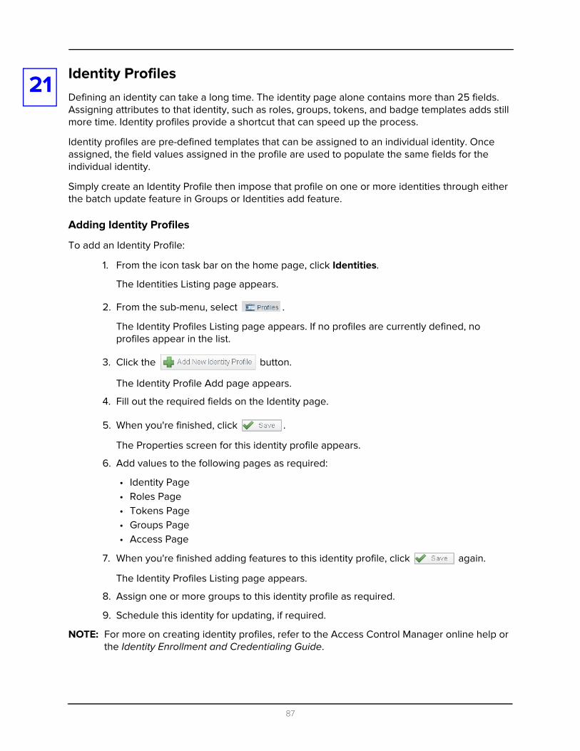
21
Identity ProfilesDefining an identity can take a long time. The identity page alone contains more than 25 fields. Assigning attributes to that identity, such as roles, groups, tokens, and badge templates adds still more time. Identity profiles provide a shortcut that can speed up the process.Identity profiles are pre-defined templates that can be assigned to an individual identity. Once assigned, the field values assigned in the profile are used to populate the same fields for the individual identity.
Simply create an Identity Profile then impose that profile on one or more identities through either the batch update feature in Groups or Identities add feature.
Adding Identity Profiles
To add an Identity Profile:
1. From the icon task bar on the home page, click Identities.
The Identities Listing page appears.
2. From the sub-menu, select .
The Identity Profiles Listing page appears. If no profiles are currently defined, no profiles appear in the list.
3. Click the button.
The Identity Profile Add page appears.
4. Fill out the required fields on the Identity page.
5. When you're finished, click .
The Properties screen for this identity profile appears.
6. Add values to the following pages as required:
• Identity Page• Roles Page• Tokens Page• Groups Page• Access Page
7. When you're finished adding features to this identity profile, click again.
The Identity Profiles Listing page appears.
8. Assign one or more groups to this identity profile as required.
9. Schedule this identity for updating, if required.
NOTE: For more on creating identity profiles, refer to the Access Control Manager online help or the Identity Enrollment and Credentialing Guide.
87

22
ReportsThe qualified operator can generate reports, in either PDF or CSV format, concerning many areas of Access Control Manager system function including:• Access Grant via Operator• Access Groups• Action Audit• Alarms• Appliance• Area• Audit Log• Cameras• Collaboration• Delegation• Delegation Comparison• Door Configuration• Door/Identities with Access• Events• Event Type• Group• Holiday• Identities Photo Gallery• Identity/Doors Access• Identity Summary• Panel• Policy• Role• Schedule• Tokens• Tokens Pending Expiration Date• Transaction
To view and generate standard reports:
1. From the home page icon task bar, click the Reports option.
88

The Reports Listing page appears like this example:
2. At the required report line, do one of these:
• Click the icon to generate a PDF.
• Click the icon to generate a spreadsheet (in CSV format) based on the report.
If you select as a PDF format, a dialog box like this example appears:
If you select a spreadsheet format, a dialog box like this appears:
3. Do one of these:
89

• Click OK to display immediately the required report in the specified format.• Select the ‘Save File’ radio button then click OK. This will save the report to the
browser's download utility from where it can be retrieved and viewed as required, or moved to another location.
For information on how to customize a report, refer to Reports section in the Access Control Manager online help.
90

23
MapsUsing the Access Control Manager’s Map Designer, the qualified operator can import maps and blue prints into the application, place the inputs, outputs, and other alarm points on that map in the location where they exist, then display the map for use by operators seeking to locate the source of a specific alarm or event.To create a map:
1. Using a drawing program, create a map or, alternatively, import a map from another source, such as a blueprint or architectural design.
The drawing can be a representation of a building, floor, or room. Access Control Manager can use a drawing that is in one of these formats: GIF, JPG, or BMP.
2. Open the Map Designer by selecting the Maps icon from the Settings module.
The Map Templates Listing page appears.
3. Click the button.
The Add Map Template page appears like this example:
4. At the 'File' combo box, click and navigate to the location on your computer where you have created or imported the required map as specified in Step 1.
5. If required, at the 'Re-Size to:' text boxes, specify the dimensions of this map.
6. Click .
The map is saved and you are returned to the Map Listing page.
7. Click the name of the map you just created.
91
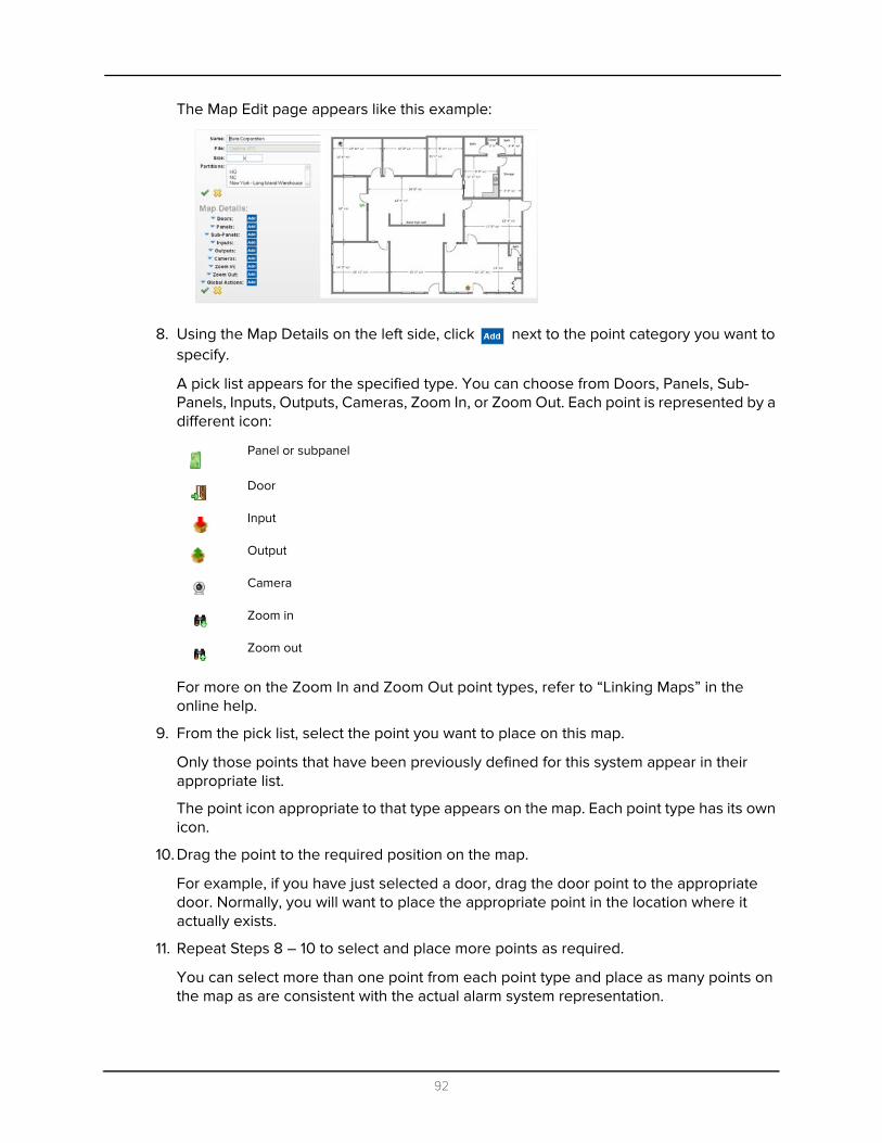
The Map Edit page appears like this example:
8. Using the Map Details on the left side, click next to the point category you want to specify.
A pick list appears for the specified type. You can choose from Doors, Panels, Sub-Panels, Inputs, Outputs, Cameras, Zoom In, or Zoom Out. Each point is represented by a different icon:
For more on the Zoom In and Zoom Out point types, refer to “Linking Maps” in the online help.
9. From the pick list, select the point you want to place on this map.
Only those points that have been previously defined for this system appear in their appropriate list.
The point icon appropriate to that type appears on the map. Each point type has its own icon.
10. Drag the point to the required position on the map.
For example, if you have just selected a door, drag the door point to the appropriate door. Normally, you will want to place the appropriate point in the location where it actually exists.
11. Repeat Steps 8 – 10 to select and place more points as required.
You can select more than one point from each point type and place as many points on the map as are consistent with the actual alarm system representation.
Panel or subpanel
Door
Input
Output
Camera
Zoom in
Zoom out
92

12. When you're finished, click to save your modifications.
At any point, you can expand the Map Details panel on the left to review the points you have defined, like this example:
(To expand the point category, simply click the button to the left of the point type; to contract the category, click the button.)
13. Click to return to the Map Listing page.
For more on using this function, refer to “How to Use Maps” in the Operators Guide.
93
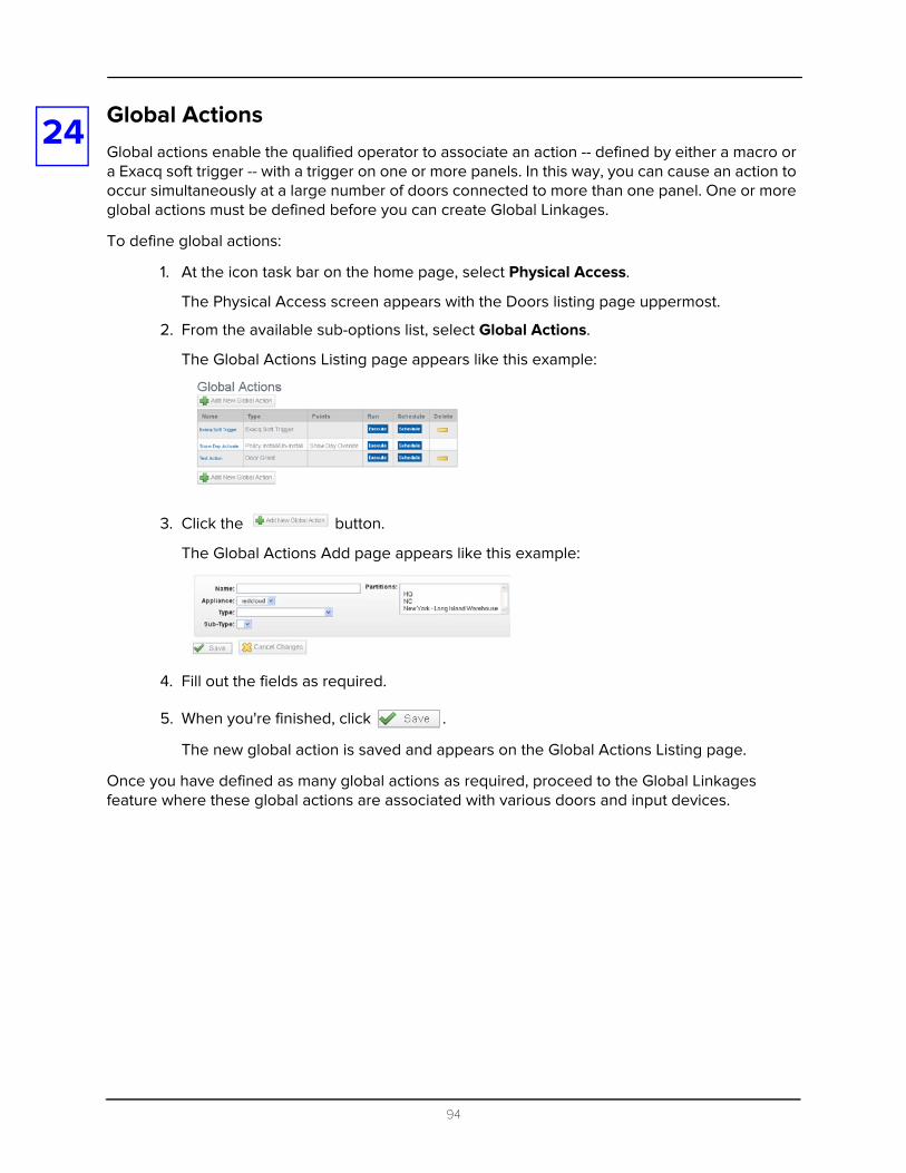
24
Global ActionsGlobal actions enable the qualified operator to associate an action -- defined by either a macro or a Exacq soft trigger -- with a trigger on one or more panels. In this way, you can cause an action to occur simultaneously at a large number of doors connected to more than one panel. One or more global actions must be defined before you can create Global Linkages.To define global actions:
1. At the icon task bar on the home page, select Physical Access.
The Physical Access screen appears with the Doors listing page uppermost.
2. From the available sub-options list, select Global Actions.
The Global Actions Listing page appears like this example:
3. Click the button.
The Global Actions Add page appears like this example:
4. Fill out the fields as required.
5. When you're finished, click .
The new global action is saved and appears on the Global Actions Listing page.
Once you have defined as many global actions as required, proceed to the Global Linkages feature where these global actions are associated with various doors and input devices.
94

25
Global LinkagesGlobal linkages are the final step in the process that defines specific actions for triggering events at specific doors. What separates this procedure from the Macro or Trigger features available for specific doors or panels, is that this feature is capable of connecting many doors and inputs spread across many panels.For example, you could lock down an entire building simply by issuing a single trigger. At a more sophisticated level, you can use global linkages to plot a complex scenario, like a sally port or a man trap, in which a series of doors are opened in sequence, inputs associated with those doors are sequentially masked and unmasked, and cameras are turned on as each door is opened.
Global linkages enable the qualified operator to plan a cascade of triggers and their resulting actions with only a single code entry or command.
To create a global linkage:
1. At the icon task bar on the home page, select Physical Access.
The Physical Access screen appears with the Doors listing page uppermost.
2. From available sub-options list, select Global Linkages.
The Global Linkages Listing page appears like this example:
3. Click the button.
The Global Linkages Add page appears like this example:
4. Fill out the fields on this page, then click .
The Global Linkages edit screen appears like this example:
5. Fill out the fields as required on each of the following pages:
95

• Linkages page• Devices page• Events page• Actions page
For more information on each page, refer to the online help.
6. When you're finished, click .
96
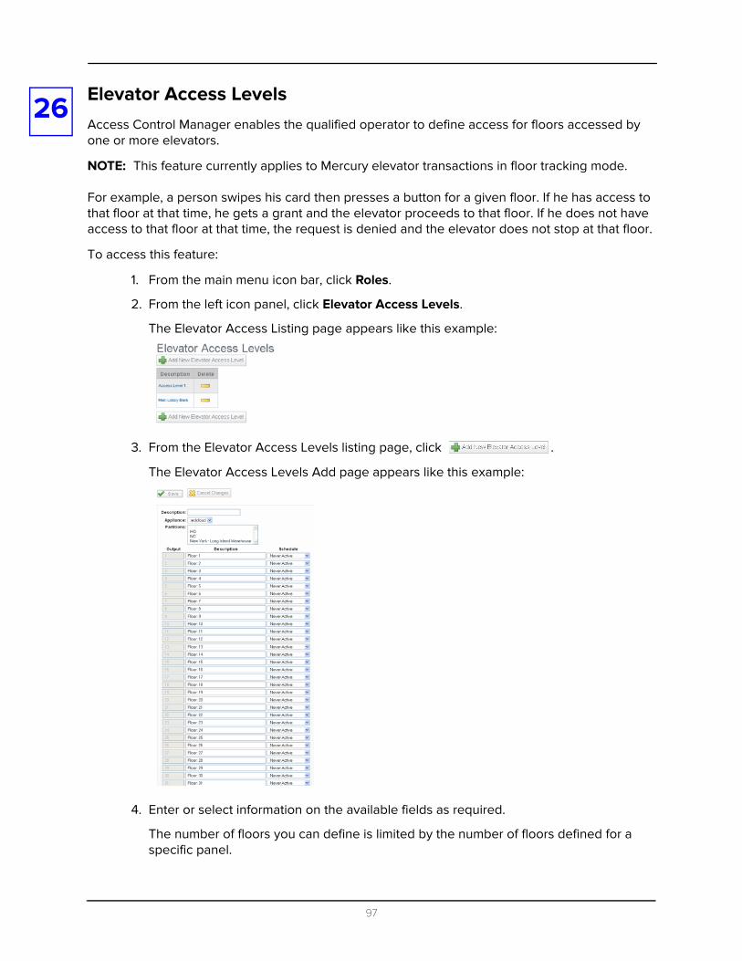
26
Elevator Access LevelsAccess Control Manager enables the qualified operator to define access for floors accessed by one or more elevators.NOTE: This feature currently applies to Mercury elevator transactions in floor tracking mode.
For example, a person swipes his card then presses a button for a given floor. If he has access to that floor at that time, he gets a grant and the elevator proceeds to that floor. If he does not have access to that floor at that time, the request is denied and the elevator does not stop at that floor.
To access this feature:
1. From the main menu icon bar, click Roles.
2. From the left icon panel, click Elevator Access Levels.
The Elevator Access Listing page appears like this example:
3. From the Elevator Access Levels listing page, click .
The Elevator Access Levels Add page appears like this example:
4. Enter or select information on the available fields as required.
The number of floors you can define is limited by the number of floors defined for a specific panel.
97

5. When you're finished, click .
The new access level appears on the listing page.
98
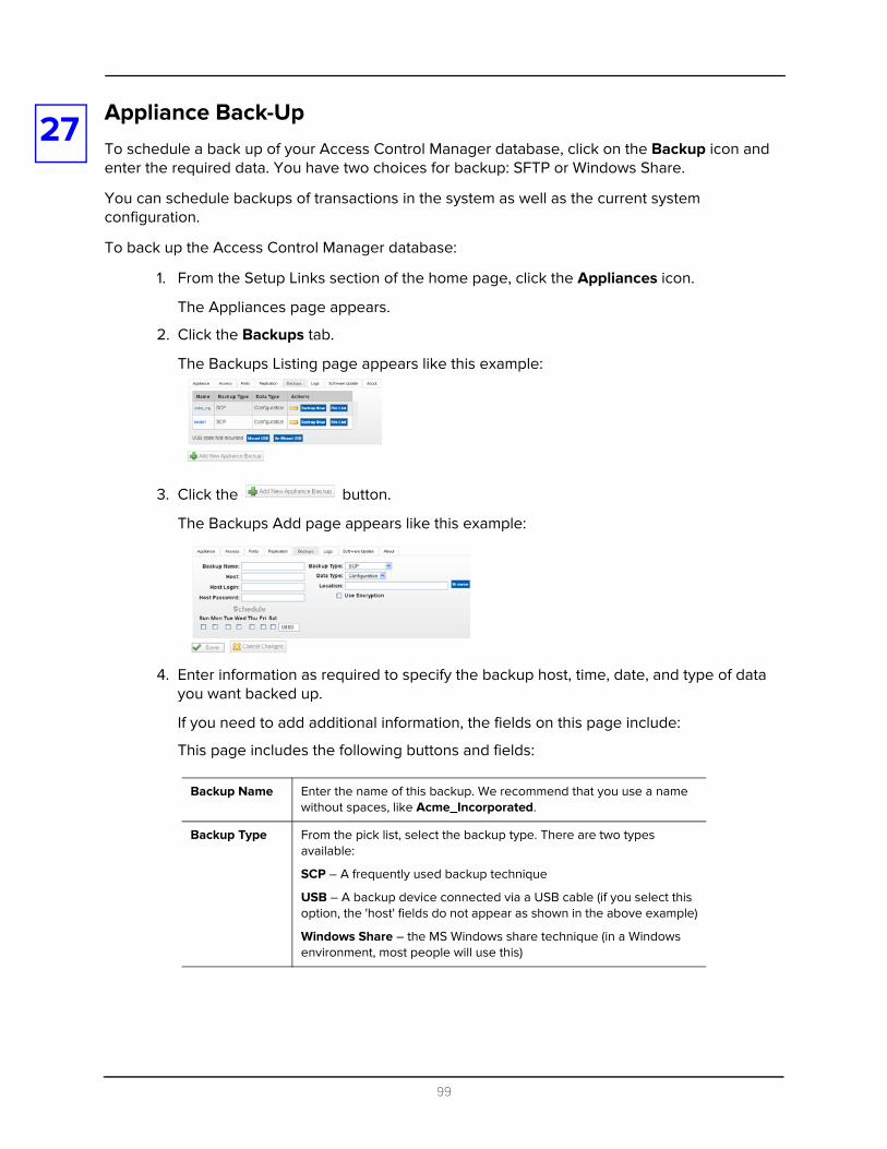
27
Appliance Back-UpTo schedule a back up of your Access Control Manager database, click on the Backup icon and enter the required data. You have two choices for backup: SFTP or Windows Share.You can schedule backups of transactions in the system as well as the current system configuration.
To back up the Access Control Manager database:
1. From the Setup Links section of the home page, click the Appliances icon.
The Appliances page appears.
2. Click the Backups tab.
The Backups Listing page appears like this example:
3. Click the button.
The Backups Add page appears like this example:
4. Enter information as required to specify the backup host, time, date, and type of data you want backed up.
If you need to add additional information, the fields on this page include:
This page includes the following buttons and fields:
Backup Name Enter the name of this backup. We recommend that you use a name without spaces, like Acme_Incorporated.
Backup Type From the pick list, select the backup type. There are two types available:
SCP – A frequently used backup technique
USB – A backup device connected via a USB cable (if you select this option, the 'host' fields do not appear as shown in the above example)
Windows Share – the MS Windows share technique (in a Windows environment, most people will use this)
99

5. Click to save your new backup.
The new backup is saved.
Host If you are using Windows Share, enter the IP address of the computer on which the share file will appear and the directory separated by a forward slash (/). An example of this format is shown in this example:
If you are using SCP, enter just the host name (which can be just the IP address) without the directory.
Data Type From the pick list, select the data type. These are two types available:
Configuration – back up all configuration data from the appliance to the host
Transactions – back up all data concerning transactions from the appliance to the host
Host Login Enter the login name required to log into the share.
Location Enter the name of the subdirectory where the backup files are stored on the host computer as shown in the above example. If the file is to be located in a subdirectory of the share, use this format:
/directory_name/
Notice that the directory name needs both a leading slash and a trailing slash. If the file is to be located in the top level of the share (no subdirectory), use this format:
/directory_name
Notice that there is only one leading slash required.
There must be an entry in the Location field for the backup to work.
Host Password Enter the password required to log onto the share.
Use Encryption Check this box to indicate that information sent between the appliance and the host is encrypted for security using AES 256-bit encryption. The password (key) for the encrypted file is by default the name of the appliance.
Schedule Check the days of the week on which a backup is to take place.
Start Time Enter the time at which the backup takes place on the designated days. This field uses a 24-hour clock.
100

28
MonitoringWhen you click the Monitor option on the icon task bar of the home page, the Monitor feature appears with the Event page uppermost. The pages of the Monitor feature enable the operator to view second-by-second information about events and alarms occurring throughout the system.This feature also provides a search filter to specify which physical devices to display and monitor as well as a verification tool to ascertain whether a specific code or card is properly assigned.
The monitor screen is divided into six pages:
• Events• Alarms• Search• Verification• HW Status• Maps
Each of these pages is explained in the following subsections.
Monitoring Events
When you click the Events tab, the Monitor Transactions page appears like this example:
This page contains information about all system activity, including system user activity, in the Access Control Manager system.
Buttons on this page are:
101
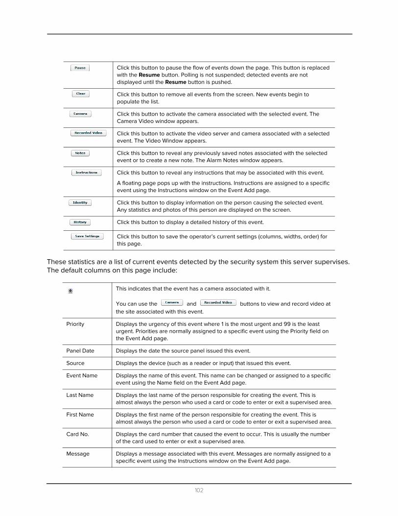
These statistics are a list of current events detected by the security system this server supervises. The default columns on this page include:
Click this button to pause the flow of events down the page. This button is replaced with the Resume button. Polling is not suspended; detected events are not displayed until the Resume button is pushed.
Click this button to remove all events from the screen. New events begin to populate the list.
Click this button to activate the camera associated with the selected event. The Camera Video window appears.
Click this button to activate the video server and camera associated with a selected event. The Video Window appears.
Click this button to reveal any previously saved notes associated with the selected event or to create a new note. The Alarm Notes window appears.
Click this button to reveal any instructions that may be associated with this event.
A floating page pops up with the instructions. Instructions are assigned to a specific event using the Instructions window on the Event Add page.
Click this button to display information on the person causing the selected event. Any statistics and photos of this person are displayed on the screen.
Click this button to display a detailed history of this event.
Click this button to save the operator’s current settings (columns, widths, order) for this page.
This indicates that the event has a camera associated with it.
You can use the and buttons to view and record video at the site associated with this event.
Priority Displays the urgency of this event where 1 is the most urgent and 99 is the least urgent. Priorities are normally assigned to a specific event using the Priority field on the Event Add page.
Panel Date Displays the date the source panel issued this event.
Source Displays the device (such as a reader or input) that issued this event.
Event Name Displays the name of this event. This name can be changed or assigned to a specific event using the Name field on the Event Add page.
Last Name Displays the last name of the person responsible for creating the event. This is almost always the person who used a card or code to enter or exit a supervised area.
First Name Displays the first name of the person responsible for creating the event. This is almost always the person who used a card or code to enter or exit a supervised area.
Card No. Displays the card number that caused the event to occur. This is usually the number of the card used to enter or exit a supervised area.
Message Displays a message associated with this event. Messages are normally assigned to a specific event using the Instructions window on the Event Add page.
102

Monitoring Alarms
When you click on the Alarms tab on the Monitor screen, a page like this appears:
Any alarms detected are listed in the Acknowledged Alarms window and the server will beep.
This page contains a row of buttons at the top and two windows.
The buttons include these:
In addition to the button bar, there are two windows:
Click this button to acknowledge one or more selected alarms. The selected alarms are moved from the Unacknowledged Alarms window to the Acknowledged Alarms window.
Click this button to remove one or more selected alarms from either one of the alarm windows. The selected alarms are permanently deleted.
Click this button to acknowledge all alarms in the Unacknowledged Alarms window.
Click this button to clear all alarms in the Acknowledged Alarms window.
Click this button to activate the camera associated with the selected alarm. The Camera Video window appears.
Click this button to activate the video server and camera associated with a selected alarm. The Video Window appears.
Click this button to reveal any previously saved notes associated with the selected alarm or to create a new note. The Alarm Notes window appears.
Click this button to reveal any instructions that may be associated with this alarm. A floating page pops up with the instructions. Instructions are assigned to a specific alarm using the Instructions window on the Event Add page.
Click this button to display information on the person causing the selected alarm. Any statistics and photos of this person are displayed on the screen.
Click this button to display a detailed history of this alarm.
Click this button to save the operator’s current settings (columns, widths, order) for this page.
Click this button to turn the alarm beeping off. The button toggles to a Sound On button. If the sound is already off and you want to turn it back on, click the Sound On button.
103
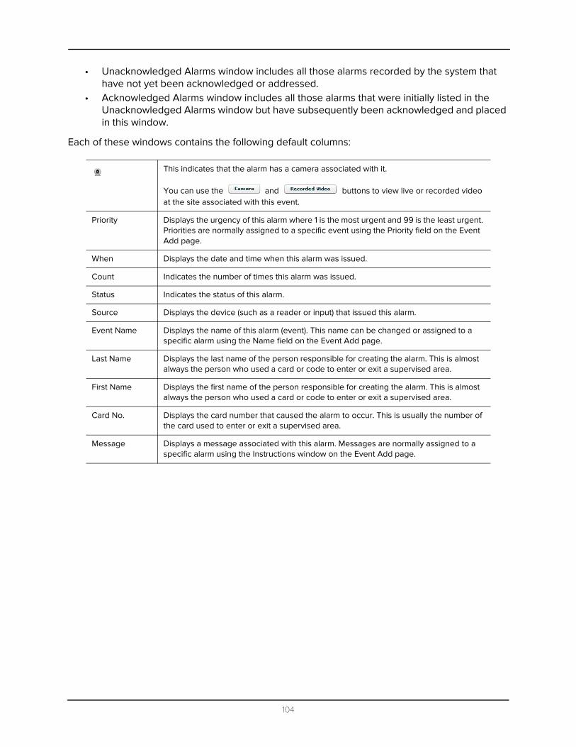
• Unacknowledged Alarms window includes all those alarms recorded by the system that have not yet been acknowledged or addressed.
• Acknowledged Alarms window includes all those alarms that were initially listed in the Unacknowledged Alarms window but have subsequently been acknowledged and placed in this window.
Each of these windows contains the following default columns:
This indicates that the alarm has a camera associated with it.
You can use the and buttons to view live or recorded video at the site associated with this event.
Priority Displays the urgency of this alarm where 1 is the most urgent and 99 is the least urgent. Priorities are normally assigned to a specific event using the Priority field on the Event Add page.
When Displays the date and time when this alarm was issued.
Count Indicates the number of times this alarm was issued.
Status Indicates the status of this alarm.
Source Displays the device (such as a reader or input) that issued this alarm.
Event Name Displays the name of this alarm (event). This name can be changed or assigned to a specific alarm using the Name field on the Event Add page.
Last Name Displays the last name of the person responsible for creating the alarm. This is almost always the person who used a card or code to enter or exit a supervised area.
First Name Displays the first name of the person responsible for creating the alarm. This is almost always the person who used a card or code to enter or exit a supervised area.
Card No. Displays the card number that caused the alarm to occur. This is usually the number of the card used to enter or exit a supervised area.
Message Displays a message associated with this alarm. Messages are normally assigned to a specific alarm using the Instructions window on the Event Add page.
104
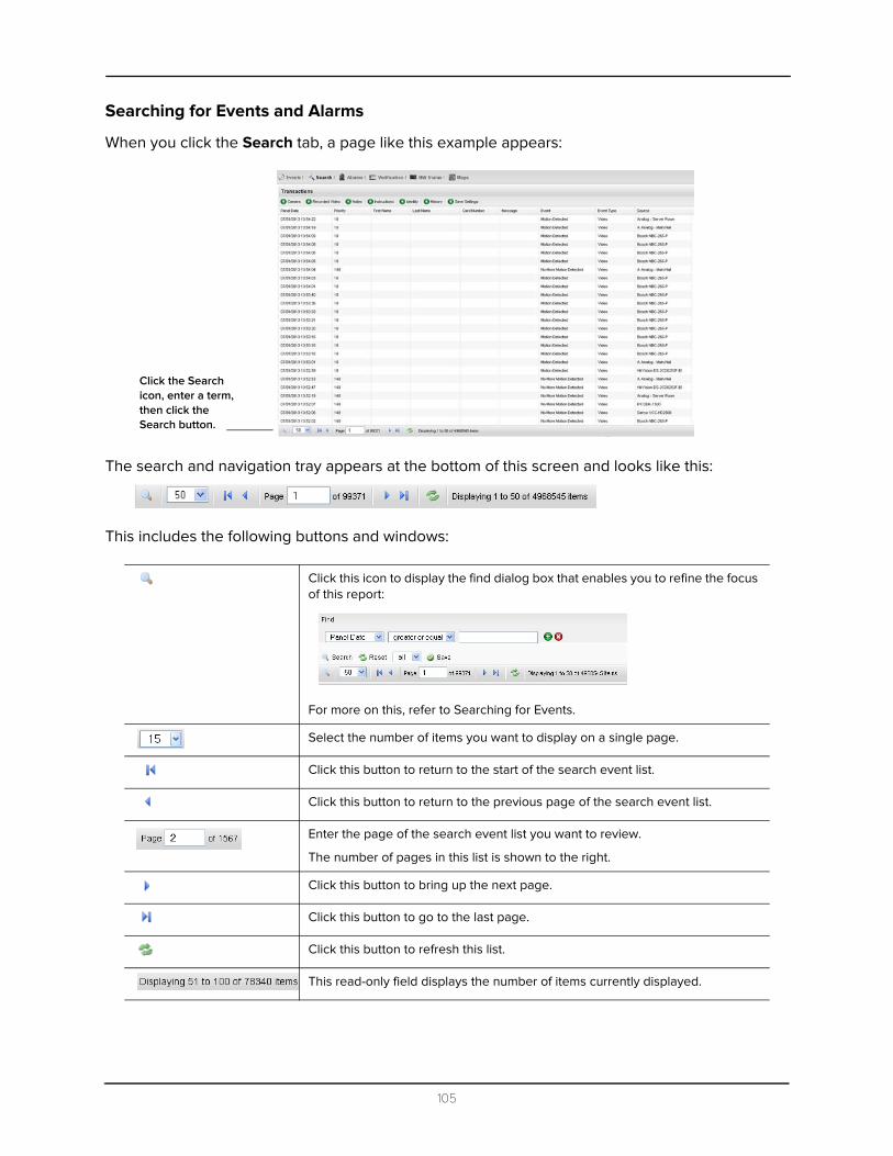
Searching for Events and Alarms
When you click the Search tab, a page like this example appears:
The search and navigation tray appears at the bottom of this screen and looks like this:
This includes the following buttons and windows:
Click this icon to display the find dialog box that enables you to refine the focus of this report:
For more on this, refer to Searching for Events.
Select the number of items you want to display on a single page.
Click this button to return to the start of the search event list.
Click this button to return to the previous page of the search event list.
Enter the page of the search event list you want to review.
The number of pages in this list is shown to the right.
Click this button to bring up the next page.
Click this button to go to the last page.
Click this button to refresh this list.
This read-only field displays the number of items currently displayed.
Click the Search icon, enter a term, then click the Search button.
105

The buttons on this screen include these:
To search for a specific transaction – event, alarm, or item – within the monitor database, do this:
1. Go to the search and navigation bar at the bottom of the screen and click the icon.
The Search area appears like this example:
2. From the drop-down pick list, select the search term you want to use as a filter.
3. From the 'equal' drop-down pick list, select the argument to use with the search term. The available argument options include:
4. In the text window to the right, enter the value you require to complete this search argument.
This term can be any text string, including any combination of alphanumeric characters with the exception of the asterisk character, *, which is reserved as a wildcard character.
Click this button to activate the camera associated with the selected alarm or event. The Camera Video window appears.
Click this button to activate the video server and camera associated with a selected alarm or event. The Video Window appears.
For more on this feature, refer to the Operator’s Guide.
Click this button to enter notes and/or reveal any previously saved notes associated with the selected alarm/event. The Alarm Notes window appears.
For more on this feature, refer to the Operator’s Guide.
Click this button to reveal any instructions that may be associated with this alarm or event. A floating page pops up with the instructions.
For more on this feature, refer to the Operator’s Guide.
Instructions are assigned to a specific alarm using the Instructions window on the Event Add page.
Click this button to display information on the person causing the selected alarm or event. Any statistics and photos of this person are displayed on the screen.
Click this button to display a detailed history of this alarm or event.
Click this button to save the operator’s current settings (columns, widths, order) for this page.
106

The string you enter can represent any item that appears in the “Source Location”, “Source Name”, “Last Name”, “Message” or “Event Name”. The wildcard * can be used along with other characters such as:
• s* - any of the above fields starting with “s”• *s - any of the above fields ending with “s”• *s* - any of the above fields with “s” anywhere in them
5. If you require additional search arguments, click to enter another line of fields like this example:
Use as many lines as you require to specify your full search criteria.
6. When you have completed your search arguments, click .
A list of all events that include the specified search string appear in the table.
7. Select one or more alarms or events and use the available buttons to control or monitor the listed event. Those items marked with a icon indicate that it has a video camera associated with the alarm/event. For more on these, refer to “Monitor Screen - Recording Video” in the online help.
8. Repeat Steps 1 - 7 for more searches.
9. To save a search term, click .
Verifying Door and Identity Status
When you click the Verification tab on the Monitor screen, a page like this example appears:
This feature enables a qualified operator to review information, including photos, about card holders entering or exiting a specified door.
To use this feature:
1. Click the Verification tab.
107
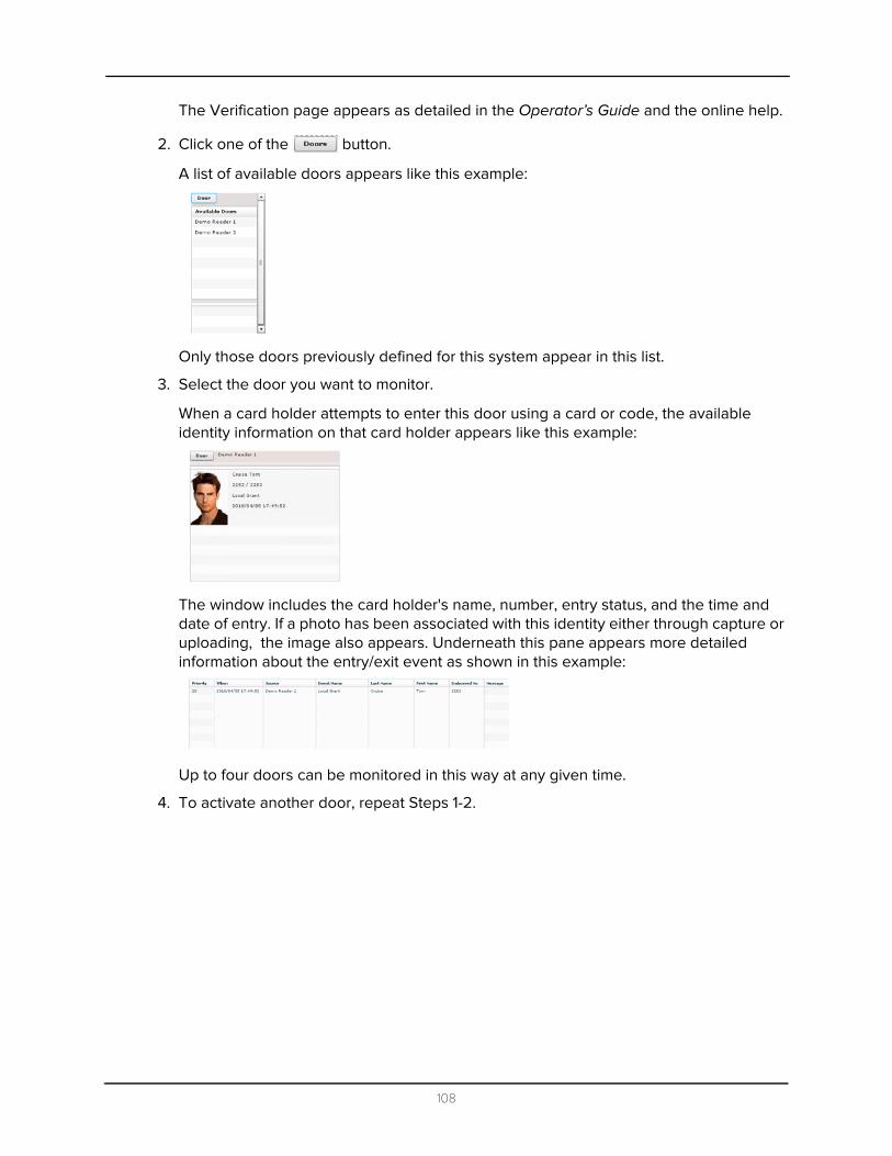
The Verification page appears as detailed in the Operator’s Guide and the online help.
2. Click one of the button.
A list of available doors appears like this example:
Only those doors previously defined for this system appear in this list.
3. Select the door you want to monitor.
When a card holder attempts to enter this door using a card or code, the available identity information on that card holder appears like this example:
The window includes the card holder's name, number, entry status, and the time and date of entry. If a photo has been associated with this identity either through capture or uploading, the image also appears. Underneath this pane appears more detailed information about the entry/exit event as shown in this example:
Up to four doors can be monitored in this way at any given time.
4. To activate another door, repeat Steps 1-2.
108

Monitoring Hardware Status
When you click the HW Status tab from the Monitor screen, a page like this example appears:
This page displays the current status of all connected panels, doors, inputs, outputs and associated security devices. A qualified operator can also use this screen to control certain aspects of installed readers.
These fields and buttons are defined below:
Appliance name Displays the time this Access Control Manager appliance has been running.
Timestamp Displays the date and time when the appliance initially went online.
Up Displays the time this Access Control Manager server has been running.
RAM Displays the number of megabytes (MB) the Access Control Manager server currently possesses.
Flash Displays the MB of flash memory the Access Control Manager appliance currently contains.
Disk Indicates the total number of MB the Access Control Manager server hard driver contains.
Load Indicates the current compute load the Access Control Manager server is experiencing.
Port Indicates the ports the server is currently using to connect to the Access Control Manager. Eight ports are displayed.
Link Indicates the current state of the link supported by the indicated port. This is either Normal or None.
109

Rx Indicates the number of data packets the designated Access Control Manager server port has received.
Tx Indicates the number of data packets the designated Access Control Manager server port has transmitted.
Doors The status of connected doors in these three categories: Offline Active Masked
Panels The status of connected panels in these categories: Offline Active
Inputs The status of connected inputs in these three categories: Offline Active Masked
Subpanels The status of connected subpanels in these categories: Offline Active
Click this button to disable the specified door. This keeps it from operating and allows no access.
Click this button to unlock the specified door. This door will remain unlocked until the Lock command is issued, or until another change of state is directed, either via operator override or scheduled action.
Click this button to lock the specified door. This door will remain locked until the Unlock command is issued, or until another change of state is directed, either via operator override or scheduled action.
Click this button to grant the current user access to the specified door. The door will be momentarily unlocked to permit a single time entry through the door.
Click this button to reset the doors's configuration values to their default value.
Click this button to mask the Door Held Open alarm for this door.
Click this button to unmask the Door Held Open alarm for this door.
Click this button to mask the Forced Held Open alarm for this door.
Click this button to unmask the Door Forced Open alarm for this door.
110

All / None Check the individual box next to the door to indicate that the door on this line should be included in the control panel above.
If you click on All in the title line, it automatically checks the boxes of all listed doors; the word changes to None.
If all doors are currently listed, click None to deselect all listed doors.
Name The name assigned to this door.
Installed The status of the door's installation: or . This field is selectable and can be toggled.
Manuf The vendor or manufacturer of this door.
Panel The name of the panel to which this door is connected.
Status of communications between the door and specified panel. The color indicates the current status.
Indicates whether this door is locked or not. The color indicates the current status.
Indicates the status of the power on the door. The color indicates the current status.
Indicates the status of the tamper switch on the door. The color indicates the current status.
Indicates the status of the battery backup on the door. The color indicates the current status.
Indicates whether this door is in a forced state. The color indicates the current status.
Indicates whether this door is currently in a held open state. The color indicates the current status.
111

Name The name assigned to the panel.
To expand this panel and review the dependent components -- such as subpanels, inputs, and outputs - controlled by this panel, click on the name. The contingent subpanels appear like this example:
To expand a subpanel to reveal the inputs and outputs controlled by a specific subpanel or panel, click on a selected subpanel and the components controlled by that subpanel appear as shown in this example:
You can bore down to the input and output component level, if needed, to review and control relevant components.
Installed The status of the panel's installation: or . This field is selectable and can be toggled.
Status of communications between the door and specified panel. The color indicates the current status.
Indicates the status of the power on the door. The color indicates the current status.
Indicates the status of the tamper switch on the door. The color indicates the current status.
Indicates the status of the battery backup on the door. The color indicates the current status.
112

Sub-Panel Status
Indicates the number of the sub-panels attached to this panel. Each relevant subpanel is displayed together with its current status. The color indicates the current status.
Subpanel The name of this subpanel. To drill down into the inputs and outputs associated with this subpanel, click this link.
C Status of communications between the panel and specified sub-panels. The color indicates the current status.
P Indicates the status of the power on this panel. The color indicates the current status.
T Indicates the status of the tamper switch on this panel. The color indicates the current status.
Installed The status of the sub-panel's installation: or . This field is selectable and can be
toggled.
Input This column lists all the inputs controlled by this subpanel, with the name and address of each input.
Cmd If allowed, one or more functions that can be performed on the input. The possible functions are:
- Click this button to mask the specified input.
- Click this button to unmask a previously masked input.
Output This column lists all the outputs (including relays and locks) controlled by this subpanel, with name and address of each output.
Cmd If allowed, click one or more of these functions that can be performed on the output.
The possible functions are:
- Click this button to power the output. If this output is a door, it energizes the circuit.
- Click this button to turn off the power to this output. If this output is a door, it de-energizes the circuit.
- Click this button to alternately energize and de-energize this output. The pulse interval is determined by the output’s settings.
113

This is the color legend used by both the doors and panels.
Monitoring Maps
When you click the Map tab, a page like this example appears.
This page lists all maps that have been created and associated with this application.
Name The name of the LifeSafety panel.
Click this name to display the LSP details. Only those panels previously defined for this system appear in this list.
Installed The status of the panel's installation: or . This field is selectable and can be toggled.
Commands If allowed, click one or more of these functions that can be performed on the available and installed LifeSafety panels. The possible functions are:
- Click this button to display the current status of the displayed LifeSafety panel.
- Click this button to view the log of events/alarms recorded by the LifeSafety panel.
- Click this button to open the browser page for this remotely connected panel and make changes to the configuration as required. The page displayed is determined by the URL specified on the 'Address' field of the LifeSafety Add page.
114

To view a map of interest, simply click on the map name and the map appears. A map like this example appears with all available security points.
For more information on the Monitoring feature, refer to the Operators Alarm Monitoring Guide.
For more information on creating maps, see Maps on page 91.
115