AUXILIARY BATTERY BOX INSTALLATION INSTRUCTIONS …AUXILIARY BATTERY BOX INSTALLATION INSTRUCTIONS...
13
AUXILIARY BATTERY BOX INSTALLATION INSTRUCTIONS Assembling the Auxiliary Battery Box 1. Remove the cover from the auxiliary battery box by removing the two nuts and washers as shown (Figure 1). 2. Verify the parts of the Auxiliary Battery Box (Figure 1). Bolt Bag Battery Placement Pads Battery Hold Down Plate Battery Hold Down Pad 11" Negative (-) Black Cable 11" Positive (+) Red Cable Battery Box Frame Auxiliary Battery Box Battery Box Cover Auxiliary Battery Box PN 014948 Cover Nut Figure 1: Part Identification. Washer Washer TOMMY GATE The original hydraulic lift ョ DPN: 095222 Page 1 of 13 Rev 1 2/20/17
Transcript of AUXILIARY BATTERY BOX INSTALLATION INSTRUCTIONS …AUXILIARY BATTERY BOX INSTALLATION INSTRUCTIONS...

AUXILIARY BATTERY BOX INSTALLATION INSTRUCTIONS
Assembling the Auxiliary Battery Box
1. Remove the cover from the auxiliary battery box by removing the two nuts and washers as shown (Figure 1).
2. Verify the parts of the Auxiliary Battery Box (Figure 1).
Bolt Bag
Battery Placement Pads
Battery Hold Down Plate
Battery Hold Down Pad
11" Negative (-) Black Cable
11" Positive (+) Red Cable
Battery Box FrameAuxiliary Battery Box
Battery Box Cover
Auxiliary Battery Box PN 014948
Cover Nut
Figure 1: Part Identification.
Washer
Washer
TOMMY GATEThe original
hydraulic lift
®
DPN: 095222 Page 1 of 13 Rev 1 2/20/17

Auxiliary Battery Box Installation Instructions
Assembling the Auxiliary Battery Box
3. Install the four cord grips in the auxiliary battery box (Figure 2).
Note: Cord grip threads go toward the inside of the auxiliary battery box.
4. Fasten both circuit breakers to the auxiliary battery box with the supplied 1/4"-20 x 1" bolts, lock waskers, and nuts (Figure 3).
Note: Be careful to not over-tighten and crack the circuit breaker bases.
Figure 2: Cord Grip Installation.
Figure 3: Circuit Breaker Installation.
Install Cord Grips Here(Similar Installation for Other Two Cord Grips on Other Side)
1/4"-20 x1" Bolt
1/4" Hex Nut1/4" Lock Washer
200 AMP Circuit Breaker
DPN: 095222 Page 2 of 13 Rev 1 2/20/17

Mounting the Auxiliary Battery Box
1. Select a location on the truck or trailer frame for the auxiliary battery box to be welded.It should be mounted on the passenger side, directly ahead of the liftgate. If the wheels of the truck/ trailer prohibit this, the battery box can be mounted ahead of the wheels.
2. Verify that there is an adequate length of power cable for your truck or trailer.Truck applications use dual conductor power cable only.Trailer applicatons use dual conductor power cable from the liftgate to the auxiliary battery box and single conductor cable from the auxiliary battery box to the front of the trailer.
3. Prepare a place for the battery box frame to be welded by removing any debris, rust, and paint from the truck or trailer's crossmembers (Figure 4).
4. Remove the masking tape from the top of the battery box frame.
5. Position the battery box underneath the truck or trailer using a fork lift or other lifting device (Figure 5).
6. Weld the top of the battery box frame to the bottom of the truck or trailer's crossmembers using 1/4" fillet welds along the full width of the crossmember (Figure 5).
7. Allow the welds to cool.
8. Paint the welded surface and top portion of the battery box frame.
1/4" Fillet Weld(Weld All Adjoining Crossmembers)
Crossmember
Figure 5: Weld Locations.
Auxiliary Battery BoxLiftgate
Figure 4: Auxiliary Battery Box Location.
1/4" Fillet Weld(Weld All Adjoining Crossmembers)
DPN: 095222 Page 3 of 13 Rev 1 2/20/17
Auxiliary Battery Box Installation Instructions
6" Reccomended

Mounting the Power Socket (Trailer Applications)
1. Skip to page 9 for truck applications.
2. Verify the parts of the Auxiliary Battery Trailer Wiring Kit (Figure 6).
62' Positive (+) Red Power Cable
21" Negative (-) Black Cable Single Pole Power Socket
Auxiliary Battery Trailer Wiring KitPN 014947
Figure 6: Part Identification.
DPN: 095222 Page 4 of 13 Rev 1 2/20/17
Auxiliary Battery Box Installation Instructions

Mounting the Power Socket (Trailer Applications)
3. Locate and mark a place on the front, driver's side of the trailer for the power socket to be mounted.
Note: The power socket should be mounted in a location that will allow access to the backside of the power socket for installation.
4. Drill three holes in the front of the trailer (Figure 7).
5. Ensure that the area where the power socket will be mounted is free of any debris, rust, and paint.
6. Mount the power socket to the trailer using the supplied 5/16-18 x1-1/2" bolts, washers, and nuts (Figure 8).
Ø7/16"Ø7/16"
Ø1-7/8"
Figure 7: Power Socket Mounting Hole Dimensions.
Front of Trailer
1-7/16"
1-7/16"
Power Socket
5/16" Flat Washer
5/16" Lock Washer5/16" Hex Nut
5/16" Flat Washer
5/16"-18 x1-1/2" Bolt
Figure 8: Power Socket.
DPN: 095222 Page 5 of 13 Rev 1 2/20/17
Auxiliary Battery Box Installation Instructions
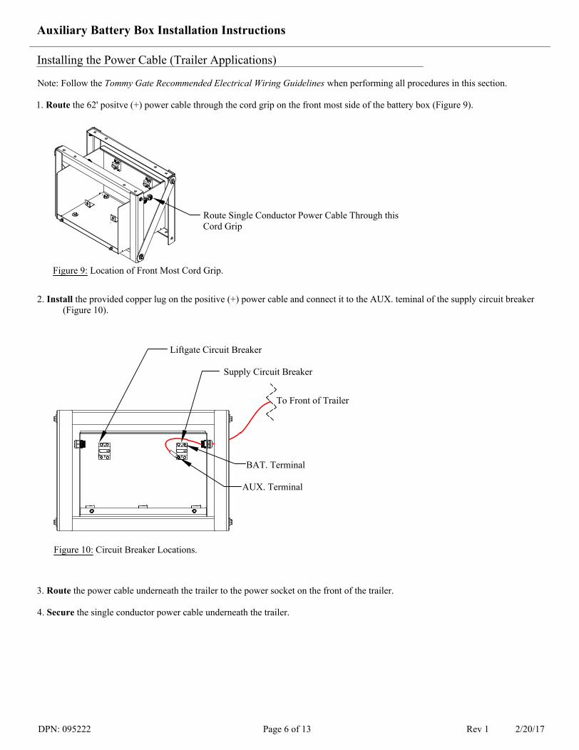
Installing the Power Cable (Trailer Applications)
Note: Follow the Tommy Gate Recommended Electrical Wiring Guidelines when performing all procedures in this section.
1. Route the 62' positve (+) power cable through the cord grip on the front most side of the battery box (Figure 9).
2. Install the provided copper lug on the positive (+) power cable and connect it to the AUX. teminal of the supply circuit breaker (Figure 10).
3. Route the power cable underneath the trailer to the power socket on the front of the trailer.
4. Secure the single conductor power cable underneath the trailer.
Route Single Conductor Power Cable Through this Cord Grip
Liftgate Circuit Breaker
Supply Circuit Breaker
Figure 10: Circuit Breaker Locations.
Figure 9: Location of Front Most Cord Grip.
To Front of Trailer
BAT. Terminal
AUX. Terminal
DPN: 095222 Page 6 of 13 Rev 1 2/20/17
Auxiliary Battery Box Installation Instructions

Installing the Power Cable (Trailer Applications)
5. Cut the excess power cable to the appropriate length to connect to the power socket.
6. Install the provided copper lug on the power cable and connect it to the terminal on the power socket (Figure 11).
7. Connect the dual conductor power cable to the liftgate's power unit by refering to the liftgate installation instructions.
8. Route the dual conductor power cable from the liftgate to the auxiliary battery box.
9. Secure the dual conductor power cable underneath the trailer.
10. Cut the dual conductor conductor cable to a length that will result in 12" of power cable to be inside the battery box.
11. Seperate the first 18"of the positive (+) and negative (-) leads of the liftgate dual conductor power cable just outside of the auxiliary battery box.
12. Route both the positive (+) and negative (-) leads from the liftgate through the cord grips at the rear most side of the battery box (Figure 12).
13. Install the provided copper lugs on both the positive (+) and negative (-) lead of the dual conductor power cable coming from the liftgate.
Connect the Positive (+) Power Cable Here
Power Socket Located on Front of Trailer
Figure 11: Backside View of Power Socket.
Route Dual Conductor Power Cable From Liftgate Through These Cord Grips
Figure 12: Locations of Rear Most Cord Grips.
DPN: 095222 Page 7 of 13 Rev 1 2/20/17
Auxiliary Battery Box Installation Instructions

Liftgate Circuit Breaker Supply Circuit Breaker
Figure 13: Placement of Power Cables.
To Front of TrailerTo Liftgate
Do Not Connect this End at this Time
Installing the Power Cable (Trailer Applications)
14. Connect the positive (+) power cable from the liftgate to the AUX. terminal of the liftgate circuit breaker (Figure 13).
Note: Do not connect the negative (-) power cable at this time.
15. Connect one end of an 11" positive (+) cable to the BAT. terminal of each circuit breaker (Figure 13).
Note: Do not connect the other ends of the 11" positive (+) cables at this time.
16. Route the 21" negative (-) ground cable through the cord grip on the front most side of the auxiliary battery box and connect it to the auxiliary battery box frame (Figure 14).
Note: Do not connect the other end of the 21" negative ground cable at this time.
21" Negative (-) Ground CableGround Bolt
Flat Washer
Flat Washer Lock WasherHex Nut
Figure 14: Ground Cable Installation.
DPN: 095222 Page 8 of 13 Rev 1 2/20/17
Auxiliary Battery Box Installation Instructions
Frontmost Side of Battery Box

Installing the Power Cable (Truck Applications)
Note: Follow the Tommy Gate Recommended Electrical Wiring Guidelines when performing all procedures in this section.
1. Skip to page 11 for trailer applications.
2. Connect the dual conductor power cable to the liftgate's power unit by refering to the liftgate installation instructions.
3. Route the dual conductor power cable from liftgate to the auxiliary battery box.
4. Secure the dual conductor power cable underneath the truck.
5. Cut the dual conductor conductor cable to a length that will result in 12" of power cable to be inside the battery box. 6. Seperate the first 18" of the positive (+) and negative (-) leads of the dual conductor power cable just outside of the auxiliary
battery box.
7. Route both the positive (+) and negative (-) leads from the liftgate through the cord grips at the rear most side of the battery box (Figure 15).
8. Install the provided copper lugs on both the positive (+) and negative (-) leads of the dual conductor power cable coming from the liftgate.
9. Connect the positive (+) power cable from the liftgate to the AUX. terminal of the liftgate circuit breaker (Figure 16).
Note: Do not connect the negative (-) ground cable from the liftgate at this time.
10. Connect one end of an 11" positive (+) power cable to the BAT. terminal of each circuit breaker (Figure 16).
Note: Do not connect the other ends of the 11" positive (+) power cables at this time.
Route Dual Conductor Power Cable From Liftgate Through these Cord Grips
Figure 15: Location of Rear Most Cord Grips.
Liftgate Circuit Breaker
Supply Circuit Breaker
Figure 16: Placement of Power Cables.
To Liftgate
Do Not Connect this End at this Time
DPN: 095222 Page 9 of 13 Rev 1 2/20/17
Auxiliary Battery Box Installation Instructions
Rear Most Side of Battery Box

Installing the Power Cable (Truck Applications)
11. Seperate the first 18" of the positive (+) and negative (-) leads of the dual conductor power cable that was previously cut off.
12. Route the positive (+) and negative (-) leads of the seperated dual conductor power cable through the cord grips on the front most side of the battery box so that there is 12" of each power cable inside the auxiliary battery box.
13. Install the provided copper lugs on both the positive (+) and negative (-) leads of the dual conductor power cable.
14. Connect the positive (+) power cable to the AUX. terminal of the supply circuit breaker (Figure 17).
Note: Do not connect the negative (-) ground cable at this time.
15. Route the dual conductor power cable from the auxiliary battery box to the vehicle's battery.
16. Secure the dual conductor power cable under the truck.
17. Refer to the liftgate installation instructions for connecting the power cable to the vehicle's batteries.
Liftgate Circuit Breaker Supply Circuit Breaker
Figure 17: Placement of Power Cables.
To Vehicle's BatteriesTo Liftgate
Do Not Connect this End at this Time
DPN: 095222 Page 10 of 13 Rev 1 2/20/17
Auxiliary Battery Box Installation Instructions

Installing the Auxiliary Batteries
Note: Follow the Tommy Gate Recommended Electrical Wiring Guidelines when performing all procedures in this section.
1. Place the two battery placement pads in the auxiliary battery box (Figure 18).
2. Push the red button on both circuit breakers to disconnect them from the rest of the circuit.
3. Place the batteries in the battery box with the positive (+) terminals closest to the circuit breakers.
4. Place the rubber hold down pad and hold down plate on top of the batteries.
5. Tighten down the hold down plate and rubber hold down pad with the three j-hooks, lock washers, and nuts (Figure 19).
6. Verify that the batteries are secure.
Note: Use 12 volt batteries only.
Battery Placement Pads
12V Batteries
Battery Hold Down Pad
J-Hook
Hex Nut
Lock Washer
Figure 18: Battery Placement Pad Locations.
Figure 19: Battery Installation.
Note: Tommy Gate recommends two group 31 AGM batteries with threaded terminal studs for the auxiliary battery box.
Battery Hold Down Plate
DPN: 095222 Page 11 of 13 Rev 1 2/20/17
Auxiliary Battery Box Installation Instructions

POS.+
Aux. Battery
NEG.- POS.+
NEG.-
POWER SOCKET
Pump Enclosure
Trailer Aux. Battery Box
Figure 20: Trailer Applications; 12V Auxiliary Battery Wiring Diagram.
Installing the Auxiliary Batteries
7. Connect the positive (+) terminals of the two batteries together using the provided 11" positive (+) red cable.
8. Connect the negative (-) terminals of the two batteries together using the provided 11" negative (-) black cable.
9. Connect the batteries to the corresponding cables by referencing the appropriate wiring diagram below (Figure 20 for trailer applications) and (Figure 21 for truck applications).
10. Verify all connections are tight and secure.
11. Verify all cord grips are tight and secure.
12. Re-engage all circuit breakers.
13. Install battery box cover.
Note: Be careful to not over-tighten the cover nuts.
POS.+NEG.- POS.
+NEG.-
Pump Enclosure
Truck Aux. Battery Box
Figure 21: Truck Applications; 12V Auxiliary Battery Wiring Diagram.
NEG.- POS.+
DPN: 095222 Page 12 of 13 Rev 1 2/20/17
Auxiliary Battery Box Installation Instructions
Pump/Motor
Pump/Motor
Solenoid May be Mounted Seperately From Motor on Some Liftgates
Solenoid May be Mounted Seperately From Motor on Some Liftgates
Aux. Battery
Aux. Battery Aux. Battery Vehicle Battery

Tommy Gate Recommended Electrical Wiring GuidelinesTOMMY GATEThe original
hydraulic lift
®
WIRE ROUTING (1) When routing wires, avoid heat (above 180ºF), abrasion, vibration, metal edges, screws, and trim fasteners. If such routings are not possible, protective devices must be used. If wires must cross a metal edge, the edge should be covered with a protective shield and the wiring fastened within 3 inches on each side of the edge. (2) Grommets must be used where wires pass through holes in sheet metal, castings, and / or frame rails. Do not bend wires in a radius smaller than 10 times the wire diameter. (3) Routing wires into areas exposed to wheel wash should be avoided. If this cannot be avoided protective shields are required to protect the wires from stones, ice, salt and water damage. Provide a drip loop to prevent moisture from being conducted into switches, relays, circuit breakers, and fuses. (4) Wires should be supported every 18 inches with plastic zip ties or rubber-lined clips. (5) Wires must be routed to clear moving parts by at least 3 inches unless positively fastened or protected by a conduit. If wiring must be routed between two members where relative motion can occur, the wiring should be secured to each member, with enough wire slack to allow flexing without damage to the wire. (6) Maintain at least a 6 inch clearance from exhaust system components. If this is not possible, high temperature insulation and heat shields are required. Existing OEM heat shields, insulation, and wire shielding must be maintained. (7) Do not route or attach electrical wires to fuel lines. Route electrical wires at least 1-1/2 inches away from the engine.
BATTERY, WIRE, TERMINALS, AND CONNECTORS (1) Wire attachments at the battery must be protected from tension loads so there is no undue strain on the battery terminals. Wires should be routed down rather than horizontally from the terminals with no sharp bends adjacent to the connections. (2) Battery power for your Tommy Gate should come directly from the battery or approved connection point through the supplied circuit breaker or fuse. The circuit breaker or fuse should be installed as close to the battery as possible. (3) Avoid splicing power cables. If splicing is necessary, the most durable splice joint will be bare metal barrel crimped, flow-soldered and covered with adhesive lined heat shrink tubing. Strip the wire ends making sure that individual conductor strands are not damaged. Use only rosin core solder, proper crimping tools, and wire with a gauge at least equivalent to the circuit being lengthened. Do not use electrical tape. (4) Battery cable terminals will be bare metal barrel crimped or flow-soldered and covered with adhesive lined heat shrink tubing. (5) Use wire connectors with locking features such as positive locking, inertia locking, bolt together, and soft mold-over with locking external retainers.
GENERAL (1) All frame contact areas must be wire brushed to bare metal, free of paint, dirt, and grease. Frame connections must be made using hardened flat washers under the bolt head and lock nuts. Corrosion preventive grease or compound is to be applied to the terminal area of the frame connection. (2) Frame cross members are not recommended as part of the ground return. (3) All circuit breakers and fuses should be located in one easily serviceable location with a means provided for identification of circuit function and current rating. If possible, avoid putting circuit breakers or fuses in the vehicle cab. (4) Before welding to the chassis disconnect the battery. Also disconnect the power train, engine, valve, and transmission control modules. (5) Do not alter vehicle ignition, starting, and / or charging systems. Do not reroute engine compartment wiring. (6) Full copper circuitry and standardized polarity grounds are recommended. (7) Never increase the rating of a factory installed fuse or circuit breaker. (8) Disconnect the battery negative (ground) wire prior to any vehicle modification.
Following the above guidelines will provide you with years of trouble free service. Failing to incorporate the above guidelines may result in a voided warranty. Non-compliance with the guidelines above may result in a failure of electrical components, shutdown of engines, loss of backup brake systems, and the possibility of fire.
DPN: 095222 Page 13 of 13 Rev 1 2/20/17
TOMMY GATEThe original
hydraulic lift
®