A.U.V. Emeric Rochford Dale Williams Bryan Douse Ryan Gray.
21
A.U.V. A.U.V. Emeric Rochford Emeric Rochford Dale Williams Dale Williams Bryan Douse Bryan Douse Ryan Gray Ryan Gray
-
Upload
beryl-moore -
Category
Documents
-
view
216 -
download
0
Transcript of A.U.V. Emeric Rochford Dale Williams Bryan Douse Ryan Gray.

A.U.V.A.U.V.Emeric RochfordEmeric Rochford
Dale WilliamsDale WilliamsBryan DouseBryan DouseRyan GrayRyan Gray

Background Background
Autonomous underwater Autonomous underwater vehicles are becoming popular in vehicles are becoming popular in many applications, including oil many applications, including oil exploration, and marine studies. exploration, and marine studies.
Underwater vehicles are also Underwater vehicles are also used to check the hulls of large ships used to check the hulls of large ships for homeland security, and for homeland security, and maintenance. maintenance.
Ryan

Mission StatementMission Statement
• Original design specifications were derived from an AUV competition in San Diego, California.
• Design an Autonomous Underwater Vehicle that can operate at depths up to 38 feet.
• The Vehicle must descend to a predetermined depth and remain at this depth during its mission.
• While underwater the AUV must remain stable on both vertical and horizontal planes.
Ryan

SolutionSolution
• Hull constructed from PVC tubingHull constructed from PVC tubing
• Four electric motor driven propellers for Four electric motor driven propellers for propulsion and steeringpropulsion and steering
• Linear leveling system for stability Linear leveling system for stability controlcontrol
• Water pressure used for depth sensingWater pressure used for depth sensing
• Use HC08 microcontrollers for Use HC08 microcontrollers for subsystem control subsystem control
Ryan

Internal System OverviewInternal System OverviewSide ViewSide View
Emeric

External System OverviewExternal System Overview
Emeric

HullHull
Emeric

Hull TestingHull Testing
Hull TestingHull Testing
•Torque = 20 ft lbsTorque = 20 ft lbs•Depth = 3.5 ftDepth = 3.5 ft•Time Submerged = 15 minTime Submerged = 15 min
No Leaks!No Leaks!
Emeric

PropulsioPropulsionn
Minimum Requirements:Minimum Requirements:
• Torque 1.012 ft lbsTorque 1.012 ft lbs• Power 0.114 hpPower 0.114 hp•Thrust 1.3 lbsThrust 1.3 lbs
Motor Selected:Motor Selected:
CerMag RS 540SCerMag RS 540S
• 12 Volts12 Volts• Thrust x2 with a 3” prop Thrust x2 with a 3” prop = 3.1lbs= 3.1lbsEmeric
Total Hydrodynamic Drag Total Hydrodynamic Drag Force of Hull = 84.9 N or Force of Hull = 84.9 N or
19.08 lbf19.08 lbf
Motor AssemblyMotor Assembly
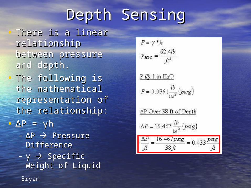
Depth SensingDepth Sensing• There is a linear There is a linear
relationship relationship between pressure between pressure and depth.and depth.
• The following is the The following is the mathematical mathematical representation of representation of the relationship:the relationship:
• ΔΔP = P = γγhh– ΔΔP P Pressure Pressure
DifferenceDifference– γγ Specific Weight Specific Weight
of Liquidof LiquidBryan

Freescale MPX4250AP Freescale MPX4250AP Ported Pressure SensorPorted Pressure Sensor
Bryan

Pressure Sensor TestsPressure Sensor TestsDepth vs Voltage
y = 0.0618x + 1.8402
1.51.75
22.25
2.52.75
33.25
3.53.75
44.25
4.54.75
5
0 5 10 15 20 25 30 35 40
Depth (ft)
Vo
lta
ge
(v
dc
)
Depth vs Voltage
Linear (Depth vsVoltage)
• The data collected from the pool test shows The data collected from the pool test shows that the sensor has a linear output of about that the sensor has a linear output of about 62mV per foot.62mV per foot.
• This gives us a full scale voltage of about This gives us a full scale voltage of about 4.25 V which provides an excellent resolution 4.25 V which provides an excellent resolution to feed into the A2D converter on the HC08.to feed into the A2D converter on the HC08.
Bryan

Leveling System DesignLeveling System DesignThe leveling system operates by redistributing
weight in the hull of the vehicle. The mechanical design consist of a motor coupled to a lead screw with a weigh threaded onto it. The motor can be commanded to turn clockwise or counter clockwise to move the mass up and down the hull as needed.
This is the only leveling system that is needed because the hull is designed in a way that most of the weight is at the bottom of the vehicle to stabilize it in the other direction.
Dale

Leveling System Control Leveling System Control CircuitCircuitThe electrical design
consists of a potentiometer with a pendulum on it to sense the angle of tilt the AUV is at. This signal is than input into two comparators to determine if the weight should be moved, and if so what direction.
Dale

Electrical OverviewElectrical Overview
``
HC08
MotorController
MotorController12 volt
battery
Opto-Isolator
Opto-Isolator
9 volt battery
LevelingMotor
Depth Control Subsystem
Propulsion Subsystem
Leveling Subsystem
Ryan
HC08
Opto-Isolator
Opto-Isolator
MotorController
MotorController
Sensors Sensors
ControlCircuit

Depth Control SystemDepth Control System
PressureSensor
Depth MotorDriver
HC08
Motor
WaterSensor
Opto-Isolator
RyanRyan

Software Overview Depth Software Overview Depth Control Control
depth equal to 30?
Ascend
Start
Surface
WaterPresent in hull?
No
Yes
No
depth Greater than 30?
descend
YesNo
Yes
// initialize variables
CMD = 200; //Value we set for our depth A2D = 0; PWM = 0; COUNT = 0;
ConfigurePorts();ConfigureTimebase();ConfigureSCI();ConfigureIRQ();StartA2D();
Void Controller (void){Call controller = 0;
//summing junction Xn = CMD – A2D;
//controllerYn = 255 * Xn;
//check and limit saturationIf ( Yn > 255.0 ){ Yn = 255.0;}
Else if ( Yn < - 255.0 ){ Yn = - 255.0;}
// load Pulse Width Modulatorif ( Yn < 0 ){ Yn =0;}PWM = ( char ) YnLoadPWM ();startA2D();return;
Ryan

Sonar OverviewSonar Overview• For the design competition our AUV is required to follow a sonar For the design competition our AUV is required to follow a sonar
ping. ping. • The sonar receiver operates by containing an array of three The sonar receiver operates by containing an array of three
sonar sensors spaced 60 degrees apart. Each of the detectors sonar sensors spaced 60 degrees apart. Each of the detectors will output independent signals into a microcontroller that will will output independent signals into a microcontroller that will than decide what direction to steer the vehicle to point it than decide what direction to steer the vehicle to point it towards the sonar transmitter. towards the sonar transmitter.
Dale

Budget Budget Section Item Price
Hull
PVC $100.00
Threaded Rod $30.00
Misc. Hardware $10.00
Gasket material $8.00
PowerSystems
Batteries $260
Motors $90.00
Motor Drivers $85
Microcontrollers $10
Sensors
Pressure sensor
circuit $10.00
Optical sensor circuit $10.00
Sonar reciver circuit $8.00
Section Item Price
LevelingSystem
Threaded rod $8.00
Motor $12.00
Misc. Hardware $10.00
Controll Circuit $15.00
Sealed Drive Shafts
X3 $60
Glue & Silicon $5.00
Total $721.00
Dale

ScheduleSchedule
Bryan

SummarySummary• Currently our hull design is complete Currently our hull design is complete
and we have assembled a sealed and we have assembled a sealed prototype.prototype.
• Our depth control system is operational Our depth control system is operational as well as our leveling system.as well as our leveling system.
• What remains to be accomplished is What remains to be accomplished is the completion and installation of our the completion and installation of our navigation system.navigation system.
Questions?Bryan