AutoSet CS 2 - ResMed INTRODUCTION C LINICIAN ’ S INTRODUCTION This booklet is a supplement to the...
79
AutoSet CS ™ 2 Clinician’s Manual User’s Manual English 268334/2 2015-10
Transcript of AutoSet CS 2 - ResMed INTRODUCTION C LINICIAN ’ S INTRODUCTION This booklet is a supplement to the...
AutoSet CS™ 2Clinician’s ManualUser’s ManualEnglish
Front Cover - CLINICAL.qxp 12/05/2006 2:36 PM Page 1
268334/2 2015-10
CLINICIAN’S MANUAL 1
USER’S MANUAL 23
AutoSet CS™ 2
USE
R’S
CLI
NIC
IAN
’S
26853r2.book Page 1 Thursday, May 11, 2006 11:05 AM

ResMed Ltd1 Elizabeth Macarthur Drive Bella Vista NSW 2153 Australia
DISTRIBUTED BYResMed Corp 9001 Spectrum Center Boulevard San Diego CA 92123 USA
ResMed (UK) Ltd 96 Jubilee Ave Milton Park Abingdon Oxfordshire OX14 4RW UKSee Resmed.com for other ResMed locations worldwide. For patent information, see Resmed.com/ip. SmartMedia is a trademark of Toshiba. Papillon is a trademark of MAP Medezin-Technologie GmbH. Activa, AutoSet CS, HumidAire, HumidAire 2i, HumidAire 2iC, Mirage, ResControl, ResLink, SmartStart, Smart Data, Ultra Mirage and Vista are trademarks of ResMed Ltd. © 2015 ResMed Ltd. 268334/2 2015-10
ResMed.com

CLI
NIC
IAN
’S
1
CLINICIAN’S MANUAL
AutoSet CS™ 2
26853r2clin.book Page 1 Wednesday, October 14, 2015 4:03 PM
2
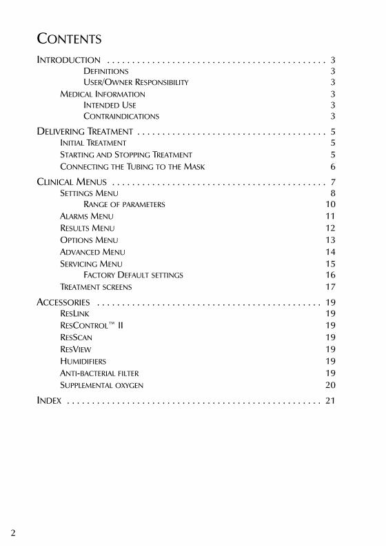
CONTENTS
INTRODUCTION . . . . . . . . . . . . . . . . . . . . . . . . . . . . . . . . . . . . . . . . . . . . 3DEFINITIONS 3USER/OWNER RESPONSIBILITY 3
MEDICAL INFORMATION 3INTENDED USE 3CONTRAINDICATIONS 3
DELIVERING TREATMENT . . . . . . . . . . . . . . . . . . . . . . . . . . . . . . . . . . . . . . 5INITIAL TREATMENT 5STARTING AND STOPPING TREATMENT 5CONNECTING THE TUBING TO THE MASK 6
CLINICAL MENUS . . . . . . . . . . . . . . . . . . . . . . . . . . . . . . . . . . . . . . . . . . . 7SETTINGS MENU 8
RANGE OF PARAMETERS 10ALARMS MENU 11RESULTS MENU 12OPTIONS MENU 13ADVANCED MENU 14SERVICING MENU 15
FACTORY DEFAULT SETTINGS 16TREATMENT SCREENS 17
ACCESSORIES . . . . . . . . . . . . . . . . . . . . . . . . . . . . . . . . . . . . . . . . . . . . . 19RESLINK 19RESCONTROL™ II 19RESSCAN 19RESVIEW 19HUMIDIFIERS 19ANTI-BACTERIAL FILTER 19SUPPLEMENTAL OXYGEN 20
INDEX . . . . . . . . . . . . . . . . . . . . . . . . . . . . . . . . . . . . . . . . . . . . . . . . . . . 21
26853r2clin.book Page 2 Wednesday, October 14, 2015 4:03 PM
3INTRODUCTION
CLI
NIC
IAN
’S
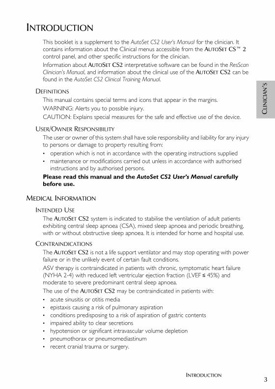
INTRODUCTIONThis booklet is a supplement to the AutoSet CS2 User’s Manual for the clinician. It contains information about the Clinical menus accessible from the AUTOSET CS™ 2 control panel, and other specific instructions for the clinician.Information about AUTOSET CS2 interpretative software can be found in the ResScan Clinician’s Manual, and information about the clinical use of the AUTOSET CS2 can be found in the AutoSet CS2 Clinical Training Manual.
DEFINITIONSThis manual contains special terms and icons that appear in the margins.WARNING: Alerts you to possible injury.CAUTION: Explains special measures for the safe and effective use of the device.
USER/OWNER RESPONSIBILITYThe user or owner of this system shall have sole responsibility and liability for any injury to persons or damage to property resulting from:• operation which is not in accordance with the operating instructions supplied• maintenance or modifications carried out unless in accordance with authorised
instructions and by authorised persons.Please read this manual and the AutoSet CS2 User’s Manual carefully before use.
MEDICAL INFORMATION
INTENDED USEThe AUTOSET CS2 system is indicated to stabilise the ventilation of adult patients exhibiting central sleep apnoea (CSA), mixed sleep apnoea and periodic breathing, with or without obstructive sleep apnoea. It is intended for home and hospital use.
CONTRAINDICATIONSThe AUTOSET CS2 is not a life support ventilator and may stop operating with power failure or in the unlikely event of certain fault conditions.ASV therapy is contraindicated in patients with chronic, symptomatic heart failure (NYHA 2-4) with reduced left ventricular ejection fraction (LVEF ≤ 45%) and moderate to severe predominant central sleep apnoea.The use of the AUTOSET CS2 may be contraindicated in patients with:• acute sinusitis or otitis media• epistaxis causing a risk of pulmonary aspiration• conditions predisposing to a risk of aspiration of gastric contents• impaired ability to clear secretions• hypotension or significant intravascular volume depletion• pneumothorax or pneumomediastinum• recent cranial trauma or surgery.
26853r2clin.book Page 3 Wednesday, October 14, 2015 4:03 PM

4
Below are general warnings and cautions. Further specific warnings, cautions and notes appear next to the relevant instructions in the manual.
!WARNINGS • The AUTOSET CS2 is NOT a life support ventilator.• Before putting patients on ASV, each patient should be assessed for heart failure.
In case of signs and symptoms of heart failure an objective assessment of LVEF should be performed.
• Check the patient’s blood pressure before, during and after 10 minutes of therapy.• The entire manual should be read before using the AUTOSET CS2.• Advice contained in this manual should not supersede instructions given by the
prescribing physician.• The AUTOSET CS2 should be used with masks and accessories recommended by
ResMed or the prescribing physician. Use of incorrect masks and accessories may adversely affect the function of the AUTOSET CS2.
• The AUTOSET CS2 is designed for use with masks that allow exhaled gases to be flushed out through vent holes. Exhaled gases will be rebreathed if the mask is worn with the machine turned off, or the vent holes are occluded. If this occurs over prolonged periods, suffocation may occur.
• In the event of power failure or machine malfunction, remove the mask from the patient.
• The air flow for breathing produced by this device can be as much as 6oC (11oF) higher than the temperature of the room. Caution should be exercised if the room temperature is warmer than 32oC (90oF).
• The AUTOSET CS2 can be set to deliver pressures up to 20 cmH2O. In the unlikely event of certain fault conditions, pressures of up to 40 cmH2O for up to 0.7 seconds are possible.
• The AUTOSET CS2 is not suitable for use in the vicinity of flammable anaesthetics.• If oxygen is used with the AUTOSET CS2, the oxygen flow should be stopped
when the device is not operating. If oxygen flow continues when the device is not operating, oxygen may accumulate within the device and create a risk of fire.
• Not for use with flammable anaesthetic mixture with oxygen or nitrous oxide.• Do not use the AUTOSET CS2 if there are obvious external defects or unexplained
changes in performance.• Do not open the AUTOSET CS2 case. There are no user serviceable parts inside.
Repairs and internal servicing should only be performed by an authorised service agent.
!CAUTIONSPatients should report unusual chest pain, severe headache or increased breathlessness. An acute upper respiratory tract infection may require temporary discontinuation of treatment.The following side effects may arise during the course of therapy with the AUTOSET CS2:• drying of the nose, mouth or throat• bloating
26853r2clin.book Page 4 Wednesday, October 14, 2015 4:03 PM
5DELIVERING TREATMENT
CLI
NIC
IAN
’S
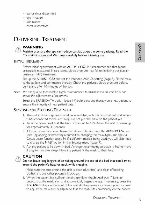
• ear or sinus discomfort• eye irritation• skin rashes• chest discomfort.
DELIVERING TREATMENT
!WARNINGPositive pressure therapy can reduce cardiac output in some patients. Read the Contraindications and Warnings carefully before initiating use.
INITIAL TREATMENT
Before initiating treatment with an AUTOSET CS2, it is recommended that blood pressure is measured. In rare cases, blood pressure may fall on initiating positive air pressure (PAP) treatment. Set up the AUTOSET CS2 and set the intended ASV-CS setting (page 8). Fit the mask to the patient and commence therapy. Check the patient’s blood pressure before, during and after 10 minutes of therapy.
NOTE The use of a full face mask is highly recommended to minimise mouth leak. Leak can impair the effectiveness of treatment.Select the ERASE DATA option (page 14) before starting therapy on a new patient to ensure the integrity of new patient data.
STARTING AND STOPPING TREATMENT
1. The unit and mask system should be assembled, with the proximal cuff and sensor tubes connected to the air tubing. Do not put the mask on the patient yet.
2. Turn the power switch at the back of the unit to ON. Allow the unit to warm up for approximately 30 seconds.
3. If the air circuit has been changed at all since the last time the AUTOSET CS2 was used (eg adding or removing a humidifier, changing the mask type), run the Air Circuit Learn function (page 9). If a different mask is being used, you will also need to change the MASK option in the Settings menu (page 9).
4. Ask the patient to lie down in bed. Arrange the air tubing so that it is free to move if they turn in their sleep. Have the patient fit the mask to their face.
!CAUTIONDo not leave long lengths of air tubing around the top of the bed that could twist around the patient’s head or neck while sleeping.
Make sure the area around the unit is clean (dust free) and clear of bedding, clothes and any other potential blockages.
5. When the patient has sufficient expiratory flow, the SMARTSTART™ function detects that the mask is on and automatically begins therapy. If necessary, press the Start/Stop key on the front of the unit. As the pressure increases, you may need to adjust the mask and headgear so that the mask sits comfortably on the patient
26853r2clin.book Page 5 Wednesday, October 14, 2015 4:03 PM

6
and does not leak. Leak and pressure can be monitored via the Treatment screens (page 17) to help obtain the best mask fit.
6. If the device stops while the mask is being positioned, breathing into the mask will restart it, or you can press the Start/Stop key again.
7. If SMARTSTOP is enabled AUTOSET CS2 will run only when the patient is breathing through the mask. If SMARTSTOP is not enabled, remove the mask and press the Start/Stop key to stop the device manually.
8. The AUTOSET CS2 restarts in the mode in which it stopped.
CONNECTING THE TUBING TO THE MASK
The proximal cuff is designed so that there is a single fitting between the mask and the air tubing. Twist the Luer lock fitting on the pressure sensor tube onto the connector on the proximal cuff, and attach the cuff to the mask.
NOTE The pressure sensor tube is placed as close as possible to the mask as part of the alarm sensing mechanism.
Figure 1: Attaching the air tubing to a mask
NOTE ResMed recommends the following tubing products for use with the AutoSet CS2: replacement air hose (only) PN 14948; replacement air delivery system (hose, sensor line, clips, proximal cuff) PN 26909.On some masks, the pressure sensor tube may also be directly connected to the mask port.
Figure 2: Attaching the pressure sensor tube directly to a mask
To attach the pressure sensor tube directly to the mask:• untwist the mask port cap
Pressure sensor tube
Proximal cuff
Mask
Pressure sensor tube
Mask port
Luer lock
26853r2clin.book Page 6 Wednesday, October 14, 2015 4:03 PM

7CLINICAL MENUS
CLI
NIC
IAN
’S
• gently detach enough of the tube clips to release the mask end of the pressure sensor tube from the air tubing
• twist the Luer lock on the pressure sensor tube onto the mask port.
CLINICAL MENUSYou can adjust the parameter settings in the Clinical menu to determine the therapy delivered to your patient by the AUTOSET CS2 system. In ASV-CS mode, the AUTOSET CS2 also makes automatic adjustments to the therapeutic pressure (magnitude and respiratory rate) in response to the patient’s breathing pattern.The Clinical menus provide access to all Patient menu functions, plus additional settings, results and options.You can enter the Clinical menus at any time from any other point in another menu. To gain access to the Clinical menus, press the Right and Up/Down keys simultaneously for 3 or more seconds.
At start up, the LCD displays the last menu used in the previous session.
!WARNINGBefore giving an AUTOSET CS2 to a patient, press ‘exit’ on the standby screen when leaving the Clinical menu to ensure that only the Patient menu is available.
Figure 3: Clinical menu standby screen
The AutoSet CS2 User’s Manual contains a full description of key functions.
CLINICALmenu exit
26853r2clin.book Page 7 Wednesday, October 14, 2015 4:03 PM

8
SETTINGS MENU
MODES
There are two mode settings available in the AUTOSET CS2 — ASV-CS mode and CPAP. ASV-CS is the default mode, indicated to stabilise the ventilation of adult patients exhibiting central sleep apnoea (CSA), mixed sleep apnoea and periodic breathing, with or without obstructive sleep apnoea. It is intended for home and hospital use.. CPAP mode is for the treatment of obstructive sleep apnoea (OSA).
ASV-CSIn ASV-CS mode, adjust EEP (end expiratory pressure) to maintain upper airway patency. Most patients will be adequately treated with an EEP of 5 cmH2O, but those with coexisting OSA may require higher pressures (eg 8 cmH2O). In the vast majority of cases the default settings will be correct and should not need to be adjusted.Pressure Support is defined as the difference between the peak pressure at the end of inspiration, and the minimum pressure at the end of expiration ie the amplitude of the pressure waveform delivered. The AUTOSET CS2 pressure support (Inspiration: Expiration and Expiration: Inspiration) trigger points are set by the AUTOSET CS2 based on measurement of the patient respiratory flow. The AUTOSET CS2 algorithm will automatically adjust pressure delivery to keep the patient’s respiratory flow even (Figure 4). See “Advanced Menu” on page 14 to set MIN PS and MAX PS.
enter exit
enter exit
enter exitSETTINGS
OPTIONS enter exit
enter exit
ALARMS
ADVANCED
RESULTS
LEAK: 0.40L/schange exit
MAX RAMP:20min
MODE: ASV-CS
EEP: 5.0cmH2O
MASK:FULL FACE
SMARTSTOP:OFF
START CPAP:4.0
RAMP:20min
MASK:FULL FACE
SMARTSTOP:OFF
LEAK ALERT:OFF
MODE: CPAPchange exit
CPAP:10cmH2O
change exit
change exit
change exit
change exit
change exit
change exit
change exit
change exit
change exit
change exit
change exit
LEARN CIRCUIT?
LEARN CIRCUIT? yes exit
enter exitSERVICING
LEAK ALERT:OFF
26853r2clin.book Page 8 Wednesday, October 14, 2015 4:03 PM
9CLINICAL MENUS
CLI
NIC
IAN
’S
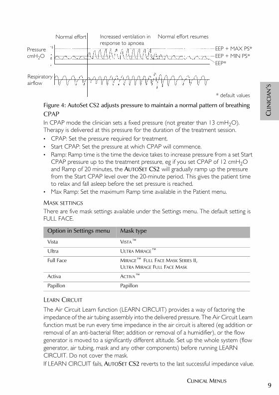
Figure 4: AutoSet CS2 adjusts pressure to maintain a normal pattern of breathingCPAPIn CPAP mode the clinician sets a fixed pressure (not greater than 13 cmH2O). Therapy is delivered at this pressure for the duration of the treatment session.• CPAP: Set the pressure required for treatment.• Start CPAP: Set the pressure at which CPAP will commence.• Ramp: Ramp time is the time the device takes to increase pressure from a set Start
CPAP pressure up to the treatment pressure, eg if you set CPAP of 12 cmH2O and Ramp of 20 minutes, the AUTOSET CS2 will gradually ramp up the pressure from the Start CPAP level over the 20-minute period. This gives the patient time to relax and fall asleep before the set pressure is reached.
• Max Ramp: Set the maximum Ramp time available in the Patient menu.
MASK SETTINGS
There are five mask settings available under the Settings menu. The default setting is FULL FACE.
LEARN CIRCUIT
The Air Circuit Learn function (LEARN CIRCUIT) provides a way of factoring the impedance of the air tubing assembly into the delivered pressure. The Air Circuit Learn function must be run every time impedance in the air circuit is altered (eg addition or removal of an anti-bacterial filter; addition or removal of a humidifier), or the flow generator is moved to a significantly different altitude. Set up the whole system (flow generator, air tubing, mask and any other components) before running LEARN CIRCUIT. Do not cover the mask.If LEARN CIRCUIT fails, AUTOSET CS2 reverts to the last successful impedance value.
EEP*EEP + MIN PS*EEP + MAX PS*Pressure
Respiratory
cmH2O
airflow
Normal effort Increased ventilation in Normal effort resumesresponse to apnoea
* default values
Option in Settings menu Mask type
Vista VISTA™Ultra ULTRA MIRAGE™Full Face MIRAGE™ FULL FACE MASK SERIES II,
ULTRA MIRAGE FULL FACE MASK
Activa ACTIVA™Papillon Papillon
26853r2clin.book Page 9 Wednesday, October 14, 2015 4:03 PM

10
SMARTSTOP
The default setting for SMARTSTOP is ON. Turn off if the patient is experiencing false SMARTSTOP events, or if you want to conduct a mask-fitting session that would create high leak between adjustments.
LEAK ALERT
The default setting for Leak Alert is ON. The Leak Alert alarm is triggered when leak rises above the threshold level of 30 L/min for more than 20 seconds.Turn off if you want to conduct a mask-fitting session, or if the patient is experiencing high leak yet wants to continue their treatment.
RANGE OF PARAMETERSThe following table sets out the ranges of the parameters that can be adjusted in the Settings menu.
* Advanced menu
AUTOSET CS2 will automatically limit to ensure that:
• MAX PS minus MIN PS is greater than or equal to 5 at all times.• EEP + MAX PS will not exceed 20 cmH2O.
To satisfy these limits:
1. Setting EEP automatically adjusts MIN PS then MAX PS.2. Setting MIN PS automatically adjusts MAX PS.
Parameter Minimum Maximum Default
ASV-CS mode
EEP (cmH2O) 4 10 5
MIN PS (cmH2O)* 3 6 3
MAX PS (cmH2O)* 8 16 10
CPAP mode
CPAP (cmH2O) 4 13 10
Start CPAP (cmH2O) 4 13 4
Ramp (minutes) 0 45 20
Max ramp (minutes) 0 45 30
26853r2clin.book Page 10 Wednesday, October 14, 2015 4:03 PM
11CLINICAL MENUS
CLI
NIC
IAN
’S
ALARMS MENU
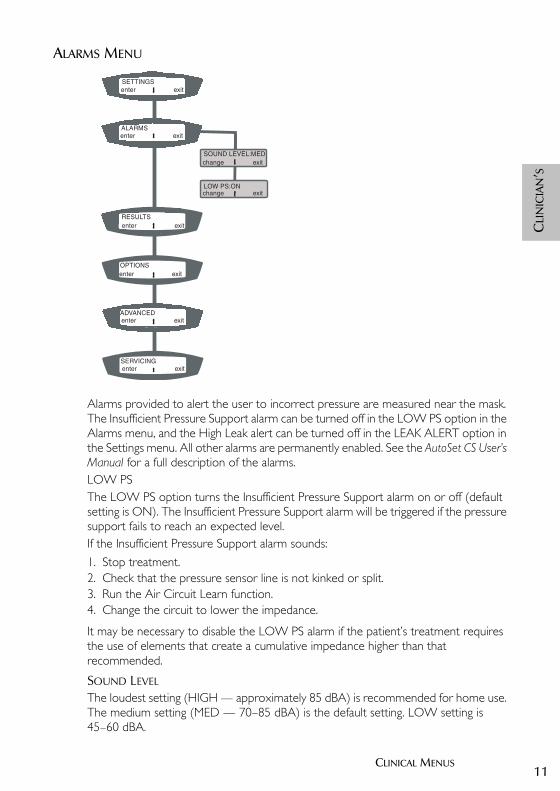
Alarms provided to alert the user to incorrect pressure are measured near the mask. The Insufficient Pressure Support alarm can be turned off in the LOW PS option in the Alarms menu, and the High Leak alert can be turned off in the LEAK ALERT option in the Settings menu. All other alarms are permanently enabled. See the AutoSet CS User’s Manual for a full description of the alarms.LOW PSThe LOW PS option turns the Insufficient Pressure Support alarm on or off (default setting is ON). The Insufficient Pressure Support alarm will be triggered if the pressure support fails to reach an expected level. If the Insufficient Pressure Support alarm sounds:
1. Stop treatment.2. Check that the pressure sensor line is not kinked or split.3. Run the Air Circuit Learn function.4. Change the circuit to lower the impedance.
It may be necessary to disable the LOW PS alarm if the patient’s treatment requires the use of elements that create a cumulative impedance higher than that recommended.
SOUND LEVEL
The loudest setting (HIGH — approximately 85 dBA) is recommended for home use. The medium setting (MED — 70–85 dBA) is the default setting. LOW setting is 45–60 dBA.
SERVICINGenter exit
SETTINGS
RESULTS
ALARMS
ADVANCEDenter exit
enter exit
enter exit
enter exit
OPTIONSenter exit
SOUND LEVEL:MEDchange exit
LOW PS:ONchange exit
26853r2clin.book Page 11 Wednesday, October 14, 2015 4:03 PM
12
RESULTS MENU
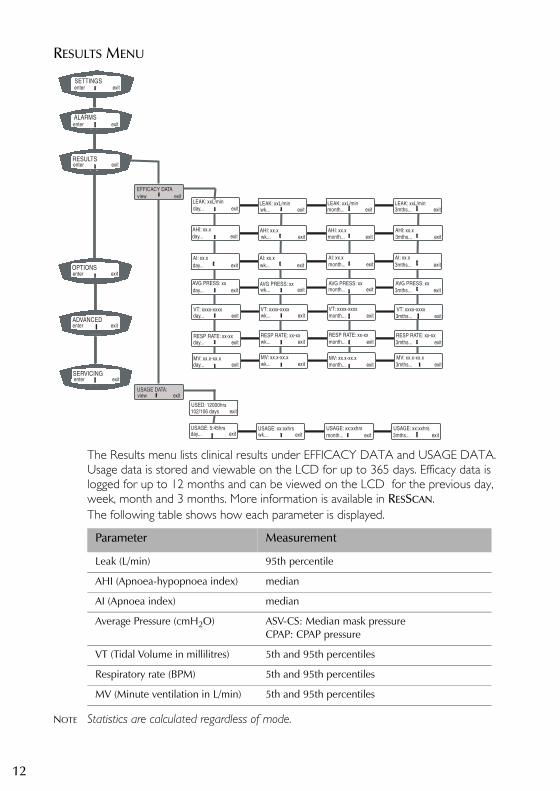
The Results menu lists clinical results under EFFICACY DATA and USAGE DATA. Usage data is stored and viewable on the LCD for up to 365 days. Efficacy data is logged for up to 12 months and can be viewed on the LCD for the previous day, week, month and 3 months. More information is available in RESSCAN.The following table shows how each parameter is displayed.
NOTE Statistics are calculated regardless of mode.
SETTINGS
OPTIONS
RESULTS
view exitEFFICACY DATA
day... exit
AHI: xx.x
wk... exitLEAK: xxL/min
AI: xx.x
AHI: xx.x
month... exitLEAK: xxL/min
AHI: xx.x
3mths... exitLEAK: xxL/min
enter exit
SERVICINGenter exit
enter exit
enter exit
day... exit
day... exit
wk... exit
wk... exit
3mths... exit
3mths... exit
AVG PRESS: xx day... exit wk... exit 3mths... exit
ALARMS enter exit
LEAK: xxL/min
AHI: xx.x
wk... exit 3mths... exit
wk... exit 3mths... exit
VT: xxxx-xxxx day... exit
RESP RATE: xx-xxday... exit
AI: xx.x AI: xx.x AI: xx.x
USAGE DATA:view exit
USED: 12000hrs102/106 days exit
USAGE: 5:45hrsday... exit
USAGE: xx:xxhrs USAGE: xx:xxhrs USAGE: xx:xxhrswk... exit month... exit 3mths... exit
wk... exit 3mths... exitMV: xx.x-xx.xday... exit
AVG PRESS: xx AVG PRESS: xx
VT: xxxx-xxxx VT: xxxx-xxxx VT: xxxx-xxxx
RESP RATE: xx-xx RESP RATE: xx-xx RESP RATE: xx-xx
MV: xx.x-xx.x MV: xx.x-xx.x MV: xx.x-xx.x
month... exit
month... exit
month... exit
month... exit
month... exit
month... exit
ADVANCEDenter exit
AVG PRESS: xx
Parameter Measurement
Leak (L/min) 95th percentile
AHI (Apnoea-hypopnoea index) median
AI (Apnoea index) median
Average Pressure (cmH2O) ASV-CS: Median mask pressureCPAP: CPAP pressure
VT (Tidal Volume in millilitres) 5th and 95th percentiles
Respiratory rate (BPM) 5th and 95th percentiles
MV (Minute ventilation in L/min) 5th and 95th percentiles
26853r2clin.book Page 12 Wednesday, October 14, 2015 4:03 PM

13CLINICAL MENUS
CLI
NIC
IAN
’S
OPTIONS MENU
SMART DATA
This function allows the clinician to turn on or off the patient’s access to information on Mask Fit, Average Pressure and Usage. The enabled parameters will appear in the patient’s Results menu. Additionally, if the AUTO APPEAR option is set to ’On’, the enabled screens will be displayed automatically on the LCD for 30 minutes after the session is completed.
NOTE AVG PRESS displays the same value in the Smart Data and Efficacy Data menus.
FACTORY DEFAULTS
To return settings to their defaults, press the Left key (’reset’) on the FACTORY DEFAULTS screen. A message will ask you to confirm the command. To continue, press the Left key again. A confirmation message is displayed for 3 seconds, then you are returned to the Clinical menu standby screen. The settings will then be configured as shown in the table “Factory Default settings” on page 16. As units are customised according to region, these settings will override those initially received.
enter exitSETTINGS
LEAK: 0.40L/senter exit
FACTORY DEFAULTS
SMART DATA
ERASE DATA?
USAGE:ON
AUTO APPEAR:ON
BACKLIGHT:AUTO
DATE:20JAN2002
MASK FIT:ONchange exit
AVG PRESS:ON
reset exit
change exit
change exit
change exit
change exit
change exit
change exit
change exit
TIME:16:54hrs
LANGUAGE:ENGLISH
enter exit
enter exit
OPTIONS enter exit
enter exit
ALARMS
SERVICING
RESULTS
yes exit
ADVANCED enter exit
26853r2clin.book Page 13 Wednesday, October 14, 2015 4:03 PM
14
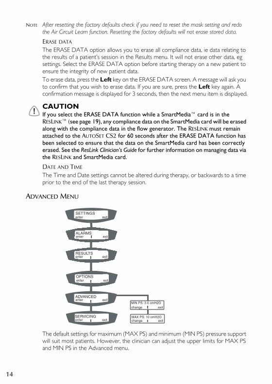
NOTE After resetting the factory defaults check if you need to reset the mask setting and redo the Air Circuit Learn function. Resetting the factory defaults will not erase stored data.
ERASE DATA
The ERASE DATA option allows you to erase all compliance data, ie data relating to the results of a patient’s session in the Results menu. It will not erase other data, eg settings. Select the ERASE DATA option before starting therapy on a new patient to ensure the integrity of new patient data.To erase data, press the Left key on the ERASE DATA screen. A message will ask you to confirm that you wish to erase data. If you are sure, press the Left key again. A confirmation message is displayed for 3 seconds, then the next menu item is displayed.
!CAUTIONIf you select the ERASE DATA function while a SmartMedia™ card is in the RESLINK™ (see page 19), any compliance data on the SmartMedia card will be erased along with the compliance data in the flow generator. The RESLINK must remain attached to the AUTOSET CS2 for 60 seconds after the ERASE DATA function has been selected to ensure that the data on the SmartMedia card has been correctly erased. See the ResLink Clinician’s Guide for further information on managing data via the RESLINK and SmartMedia card.
DATE AND TIME
The Time and Date settings cannot be altered during therapy, or backwards to a time prior to the end of the last therapy session.
ADVANCED MENU
The default settings for maximum (MAX PS) and minimum (MIN PS) pressure support will suit most patients. However, the clinician can adjust the upper limits for MAX PS and MIN PS in the Advanced menu.
enter exitALARMS
MIN PS: 3.0 cmH2O
MAX PS: 10 cmH2O
change exit
enter exit
enter exit
ADVANCEDenter exit
enter exit
RESULTS
SERVICING
OPTIONS
change exit
SETTINGS enter exit
26853r2clin.book Page 14 Wednesday, October 14, 2015 4:03 PM
15CLINICAL MENUS
CLI
NIC
IAN
’S
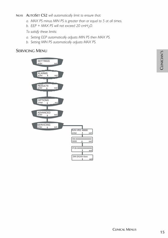
NOTE AUTOSET CS2 will automatically limit to ensure that:a. MAX PS minus MIN PS is greater than or equal to 5 at all times.b. EEP + MAX PS will not exceed 20 cmH2O.
To satisfy these limits:a. Setting EEP automatically adjusts MIN PS then MAX PS.b. Setting MIN PS automatically adjusts MAX PS.
SERVICING MENU
enter exitALARMS
RUN HRS: 88888
SN:00000000000000
PCB:0000000000000
enter exit
exit
exit
enter exit
enter exit
ADVANCEDenter exit
enter exit
RESULTS
SERVICING
OPTIONS
0000 exit
SW:SX245-0xxx
SETTINGS enter exit
26853r2clin.book Page 15 Wednesday, October 14, 2015 4:03 PM
16
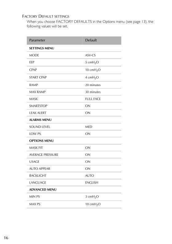
FACTORY DEFAULT SETTINGSWhen you choose FACTORY DEFAULTS in the Options menu (see page 13), the following values will be set.
Parameter Default
SETTINGS MENU
MODE ASV-CS
EEP 5 cmH2O
CPAP 10 cmH2O
START CPAP 4 cmH2O
RAMP 20 minutes
MAX RAMP 30 minutes
MASK FULL FACE
SMARTSTOP ON
LEAK ALERT ON
ALARMS MENU
SOUND LEVEL MED
LOW PS ON
OPTIONS MENU
MASK FIT ON
AVERAGE PRESSURE ON
USAGE ON
AUTO APPEAR ON
BACKLIGHT AUTO
LANGUAGE ENGLISH
ADVANCED MENU
MIN PS 3 cmH2O
MAX PS 10 cmH2O
26853r2clin.book Page 16 Wednesday, October 14, 2015 4:03 PM

17CLINICAL MENUS
CLI
NIC
IAN
’S
TREATMENT SCREENS
The LCD will display the Treatment screens when treatment commences, and during treatment if no key is pressed for 20 minutes.Press the QuickView key to move to the Treatment screens from another screen. Press the QuickView key again within 20 minutes to return to your original screen.If an alarm is triggered while you are in the Treatment screens, the arrow will flash. Press the Down key until you reach the alarm message.
TREATMENT SCREEN 1
Figure 5: Treatment screen 1
Treatment screen 1 shows:• top left: mode• top right: delivered pressure for most recent breath (cmH2O)
ASV-CS mode: Minimum pressure — Maximum pressure CPAP mode: the set pressure
• bottom left: graphical indication of instantanteous delivered pressure.
The arrow indicates that you can scroll down to the next screens. The ‘exit’ message shows that you can exit from this screen by pressing the Right key.
TREATMENT SCREEN 2
Figure 6: Treatment screen 2
Treatment screen 2 shows:• top left: leak in litres per minute (L/min)• top right: respiratory rate in breaths per minute (bpm)• bottom left: apnoea/hypopnoea indicator (blank if no apnoeas or hypopnoeas
present)• bottom right: tidal volume in millilitres (mL).
The arrow indicates that you can scroll up or down from this screen.
ASV-CS 5.0--15.0
exit
LK:18L/min RR:12
APNEA VT: 428
26853r2clin.book Page 17 Wednesday, October 14, 2015 4:03 PM
18
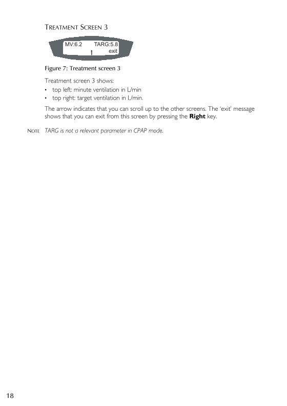
TREATMENT SCREEN 3
Figure 7: Treatment screen 3
Treatment screen 3 shows:• top left: minute ventilation in L/min• top right: target ventilation in L/min.
The arrow indicates that you can scroll up to the other screens. The ‘exit’ message shows that you can exit from this screen by pressing the Right key.
NOTE TARG is not a relevant parameter in CPAP mode.
MV:6.2 TARG:5.8
exit
26853r2clin.book Page 18 Wednesday, October 14, 2015 4:03 PM
19ACCESSORIES
CLI
NIC
IAN
’S
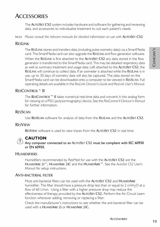
ACCESSORIESThe AUTOSET CS2 system includes hardware and software for gathering and reviewing data, and accessories to individualise treatment to suit each patient’s needs.
NOTE Please consult the relevant manuals for detailed information on use with AUTOSET CS2.
RESLINK
The RESLINK stores and transfers data (including pulse oximetry data) via a SmartMedia card. The SmartMedia card can also upgrade the RESLINK and flow generator software. When the RESLINK is first attached to the AUTOSET CS2 any data stored in the flow generator is transferred to the SmartMedia card. This may be detailed respiratory data as well as summary treatment and usage data. Left attached to the AUTOSET CS2, the RESLINK will continue to collect data. If an oximeter is attached while the RESLINK is in use, up to 30 days of oximetry data will also be captured. The data stored on the SmartMedia card can be downloaded onto a computer to be viewed in RESSCAN. Full operating details are available in the ResLink Clinician's Guide and ResLink User's Manual.
RESCONTROL™ IIThe RESCONTROL™ II takes numerical real-time data and converts it into analog form for viewing on a PSG (polysomnography) device. See the ResControl II Clinician’s Manual for further information.
RESSCAN
Use RESSCAN software for analysis of data from the RESLINK and the AUTOSET CS2.
RESVIEW
RESVIEW software is used to view traces from the AUTOSET CS2 in real time.
!CAUTIONAny computer connected to an AUTOSET CS2 must be compliant with IEC 60950 or EN 60950.
HUMIDIFIERS
Humidifiers recommended by ResMed for use with the AUTOSET CS2 are the HUMIDAIRE 2i™, HUMIDAIRE 2iC and the HUMIDAIRE™. See the AutoSet CS2 User’s Manual for setup instructions.
ANTI-BACTERIAL FILTER
Most anti-bacterial filters can be used with the AUTOSET CS2 and HUMIDAIRE humidifier. The filter should have a pressure drop less than or equal to 2 cmH2O at a flow of 60 L/min. Using a filter with a higher pressure drop may reduce the effectiveness of therapy provided by the AUTOSET CS2. Perform the Air Circuit Learn function whenever adding, removing or replacing a filter.Check the manufacturer’s instructions to see whether the anti-bacterial filter can be used with a HUMIDAIRE 2i or HUMIDAIRE 2iC.
26853r2clin.book Page 19 Wednesday, October 14, 2015 4:03 PM

20
An anti-bacterial filter with high impedance can cause safety cutouts in the AUTOSET CS2 if it is in use during the combination of:• high peak mask pressure (EEP + Max PS = 20 cmH2O)• high peak patient inspiration (>50 L/min)• significant mask leak flow (>50 L/min).
It is recommended that an anti-bacterial filter with a pressure drop less than or equal to 1 cmH2O at 60 L/min flow is used if this combination of conditions is present.
SUPPLEMENTAL OXYGEN
The AUTOSET CS2 is designed to be compatible with the use of low flow oxygen therapy provided from an external source and supplied at a fixed rate of up to 15 L/min. Actual oxygen concentrations will vary depending on the mask used, where the oxygen is introduced, pressure setting, volume delivered, leak, and patient breathing pattern.
!WARNING• If oxygen is used with this device, the oxygen flow must be turned off when the
device is not operating. Explanation: When the device is not in operation, and the oxygen flow is left on, oxygen delivered into the ventilator tubing may accumulate within the device enclosure and create a risk of fire.
• Always begin AUTOSET CS2 therapy before the oxygen supply is turned on.• Always turn the oxygen supply off before stopping AUTOSET CS2 therapy.• Oxygen supports combustion. Oxygen should not be used while smoking or in
the presence of an open flame.
26853r2clin.book Page 20 Wednesday, October 14, 2015 4:03 PM

21INDEX
CLI
NIC
IAN
’S
INDEX
Aaccessories 19air circuit learn function 9air pressure
monitoring 17alarms 11
LOW PS 11sound level 11
anti-bacterial filter 19apnoea index 12apnoea/hypopnoea indicator 17apnoea-hypopnoea index 12ASV-CS mode 8AutoSet CS2
initiating treatment 5
Bblood pressure measurement 5
Ccardiac output 5cautions 4clinical menu 7contraindications 3CPAP mode 9
Ddefault settings 16
Eefficacy data 12erase data 14
Ffactory defaults
reset 13
Hhumidifiers 19
Lleak 12, 17leak alert 10learn circuit 9
Mmask settings 9medical information 3
menusaccess to menus 7alarms menu 11options menu 13results menu 12servicing menu 15settings menu 8
minute ventilation 12, 18mode settings 8
Ooptions menu 13
Ppressure 12pressure sensor tube
attach to mask 6pressure support 8proximal cuff 6
QQuickView key 17
Rramp 9
maximum ramp 9ResControl II 19ResLink 19respiratory rate 12, 17ResScan 12, 19results menu 12
Sservicing menu 15settings
default 16settings menu 8smart data 13SmartStart 5SmartStop 6, 10standby screen 7start CPAP 9, 10starting treatment 5stopping treatment 5supplemental oxygen 20
Ttarget ventilation 18
26853r2clin.book Page 21 Wednesday, October 14, 2015 4:03 PM

22
tidal volume 12, 17treatment screens 17
Uusage data 12
Wwarnings 4
26853r2clin.book Page 22 Wednesday, October 14, 2015 4:03 PM

23
USER’S MANUALEnglish
AUTOSET CS™ 2
USE
R’S
26853r2eng.book Page 23 Wednesday, October 14, 2015 4:08 PM

24
26853r2eng.book Page 24 Wednesday, October 14, 2015 4:08 PM

25TABLE OF CONTENTS
USE
R’S
TABLE OF CONTENTS
INTRODUCTION . . . . . . . . . . . . . . . . . . . . . . . . . . . . . . . . . . . . . . . . . . . 27AUTOSET CS2 27USER/OWNER RESPONSIBILITY 27MEDICAL INFORMATION 27
INTENDED USE 27CONTRAINDICATIONS 27
WARNINGS 28CAUTIONS 28
QUICK SETUP GUIDE . . . . . . . . . . . . . . . . . . . . . . . . . . . . . . . . . . . . . . . 29
THE AUTOSET CS2 SYSTEM . . . . . . . . . . . . . . . . . . . . . . . . . . . . . . . . . . 31AUTOSET CS2 COMPONENTS 31
MASKS 32ASSEMBLING THE AUTOSET CS2 SYSTEM 33HUMIDIFIERS 35
CONNECTING A HUMIDIFIER 36HUMIDAIRE 2I™ AND HUMIDAIRE 2IC™ 36HUMIDAIRE 37
RESLINK™ 39ANTI-BACTERIAL FILTER 39USING DC POWER TO RUN THE AUTOSET CS2 40USING SUPPLEMENTAL OXYGEN 41
USING THE AUTOSET CS2 . . . . . . . . . . . . . . . . . . . . . . . . . . . . . . . . . . . 43STARTING TREATMENT 43STOPPING TREATMENT 43STANDBY MODE 43CONTROL PANEL FUNCTIONS 44ADJUSTING SETTINGS 45MENUS 47
SETTINGS MENU 48ALARMS MENU 49RESULTS MENU 49OPTIONS MENU 50SERVICING MENU 51
TREATMENT SCREENS 51
THE ALARMS . . . . . . . . . . . . . . . . . . . . . . . . . . . . . . . . . . . . . . . . . . . . . . 53LOW MASK PRESSURE ALARM 53POWER FAIL ALARM 54HIGH PRESSURE ALARM 54
26853r2eng.book Page 25 Wednesday, October 14, 2015 4:08 PM
26
HIGH LEAK ALARM 54INSUFFICIENT PRESSURE SUPPORT ALARM 55FLOW BLOCKED ALARM 55
CLEANING AND MAINTENANCE . . . . . . . . . . . . . . . . . . . . . . . . . . . . . . . 57DAILY 57WEEKLY 57PERIODICALLY 58AIR FILTER 58
HYPOALLERGENIC AIR FILTER 59
TROUBLESHOOTING . . . . . . . . . . . . . . . . . . . . . . . . . . . . . . . . . . . . . . . . 61
GLOSSARY . . . . . . . . . . . . . . . . . . . . . . . . . . . . . . . . . . . . . . . . . . . . . . . . 63
TECHNICAL SPECIFICATIONS . . . . . . . . . . . . . . . . . . . . . . . . . . . . . . . . . . 65
LIMITED WARRANTY . . . . . . . . . . . . . . . . . . . . . . . . . . . . . . . . . . . . . . . . 73
INDEX . . . . . . . . . . . . . . . . . . . . . . . . . . . . . . . . . . . . . . . . . . . . . . . . . . . 75
26853r2eng.book Page 26 Wednesday, October 14, 2015 4:08 PM
27INTRODUCTION
USE
R’S
INTRODUCTION
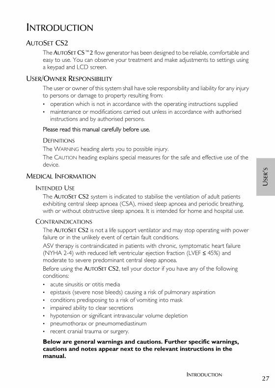
AUTOSET CS2The AUTOSET CS™2 flow generator has been designed to be reliable, comfortable and easy to use. You can observe your treatment and make adjustments to settings using a keypad and LCD screen.
USER/OWNER RESPONSIBILITY The user or owner of this system shall have sole responsibility and liability for any injury to persons or damage to property resulting from:• operation which is not in accordance with the operating instructions supplied• maintenance or modifications carried out unless in accordance with authorised
instructions and by authorised persons.
Please read this manual carefully before use.
DEFINITIONS
The WARNING heading alerts you to possible injury.The CAUTION heading explains special measures for the safe and effective use of the device.
MEDICAL INFORMATION
INTENDED USEThe AUTOSET CS2 system is indicated to stabilise the ventilation of adult patients exhibiting central sleep apnoea (CSA), mixed sleep apnoea and periodic breathing, with or without obstructive sleep apnoea. It is intended for home and hospital use.
CONTRAINDICATIONSThe AUTOSET CS2 is not a life support ventilator and may stop operating with power failure or in the unlikely event of certain fault conditions. ASV therapy is contraindicated in patients with chronic, symptomatic heart failure (NYHA 2-4) with reduced left ventricular ejection fraction (LVEF ≤ 45%) and moderate to severe predominant central sleep apnoea.Before using the AUTOSET CS2, tell your doctor if you have any of the following conditions:• acute sinusitis or otitis media• epistaxis (severe nose bleeds) causing a risk of pulmonary aspiration• conditions predisposing to a risk of vomiting into mask• impaired ability to clear secretions• hypotension or significant intravascular volume depletion• pneumothorax or pneumomediastinum• recent cranial trauma or surgery.
Below are general warnings and cautions. Further specific warnings, cautions and notes appear next to the relevant instructions in the manual.
26853r2eng.book Page 27 Wednesday, October 14, 2015 4:08 PM
28
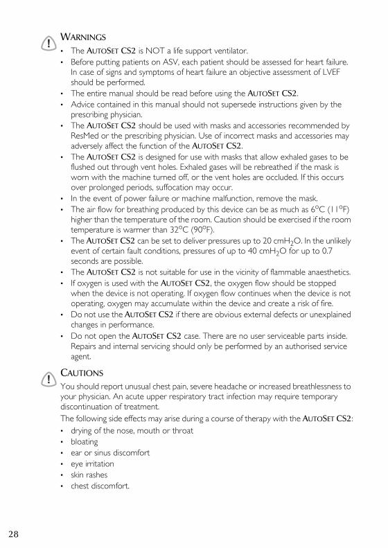
!WARNINGS
• The AUTOSET CS2 is NOT a life support ventilator.• Before putting patients on ASV, each patient should be assessed for heart failure.
In case of signs and symptoms of heart failure an objective assessment of LVEF should be performed.
• The entire manual should be read before using the AUTOSET CS2.• Advice contained in this manual should not supersede instructions given by the
prescribing physician.• The AUTOSET CS2 should be used with masks and accessories recommended by
ResMed or the prescribing physician. Use of incorrect masks and accessories may adversely affect the function of the AUTOSET CS2.
• The AUTOSET CS2 is designed for use with masks that allow exhaled gases to be flushed out through vent holes. Exhaled gases will be rebreathed if the mask is worn with the machine turned off, or the vent holes are occluded. If this occurs over prolonged periods, suffocation may occur.
• In the event of power failure or machine malfunction, remove the mask.• The air flow for breathing produced by this device can be as much as 6oC (11oF)
higher than the temperature of the room. Caution should be exercised if the room temperature is warmer than 32oC (90oF).
• The AUTOSET CS2 can be set to deliver pressures up to 20 cmH2O. In the unlikely event of certain fault conditions, pressures of up to 40 cmH2O for up to 0.7 seconds are possible.
• The AUTOSET CS2 is not suitable for use in the vicinity of flammable anaesthetics.• If oxygen is used with the AUTOSET CS2, the oxygen flow should be stopped
when the device is not operating. If oxygen flow continues when the device is not operating, oxygen may accumulate within the device and create a risk of fire.
• Do not use the AUTOSET CS2 if there are obvious external defects or unexplained changes in performance.
• Do not open the AUTOSET CS2 case. There are no user serviceable parts inside. Repairs and internal servicing should only be performed by an authorised service agent.
!CAUTIONS
You should report unusual chest pain, severe headache or increased breathlessness to your physician. An acute upper respiratory tract infection may require temporary discontinuation of treatment.The following side effects may arise during a course of therapy with the AUTOSET CS2:• drying of the nose, mouth or throat• bloating• ear or sinus discomfort• eye irritation• skin rashes• chest discomfort.
26853r2eng.book Page 28 Wednesday, October 14, 2015 4:08 PM
29QUICK SETUP GUIDE
USE
R’S
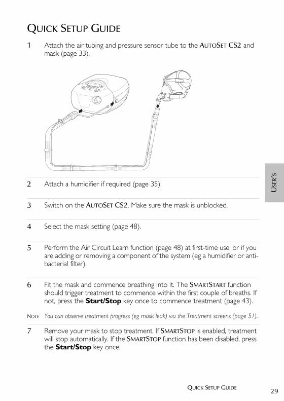
QUICK SETUP GUIDE 1 Attach the air tubing and pressure sensor tube to the AUTOSET CS2 and
mask (page 33).
2 Attach a humidifier if required (page 35).
3 Switch on the AUTOSET CS2. Make sure the mask is unblocked.
4 Select the mask setting (page 48).
5 Perform the Air Circuit Learn function (page 48) at first-time use, or if you are adding or removing a component of the system (eg a humidifier or anti-bacterial filter).
6 Fit the mask and commence breathing into it. The SMARTSTART function should trigger treatment to commence within the first couple of breaths. If not, press the Start/Stop key once to commence treatment (page 43).
NOTE You can observe treatment progress (eg mask leak) via the Treatment screens (page 51).
7 Remove your mask to stop treatment. If SMARTSTOP is enabled, treatment will stop automatically. If the SMARTSTOP function has been disabled, press the Start/Stop key once.
26853r2eng.book Page 29 Wednesday, October 14, 2015 4:08 PM

30
26853r2eng.book Page 30 Wednesday, October 14, 2015 4:08 PM
31THE AUTOSET CS2 SYSTEM
USE
R’S
THE AUTOSET CS2 SYSTEM
AUTOSET CS2 COMPONENTS
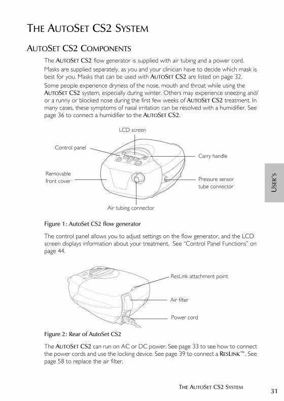
The AUTOSET CS2 flow generator is supplied with air tubing and a power cord. Masks are supplied separately, as you and your clinician have to decide which mask is best for you. Masks that can be used with AUTOSET CS2 are listed on page 32.Some people experience dryness of the nose, mouth and throat while using the AUTOSET CS2 system, especially during winter. Others may experience sneezing and/or a runny or blocked nose during the first few weeks of AUTOSET CS2 treatment. In many cases, these symptoms of nasal irritation can be resolved with a humidifier. See page 36 to connect a humidifier to the AUTOSET CS2.
Figure 1: AutoSet CS2 flow generator
The control panel allows you to adjust settings on the flow generator, and the LCD screen displays information about your treatment. See “Control Panel Functions” on page 44.
Figure 2: Rear of AutoSet CS2
The AUTOSET CS2 can run on AC or DC power. See page 33 to see how to connect the power cords and use the locking device. See page 39 to connect a RESLINK™. See page 58 to replace the air filter.
Air tubing connector
Pressure sensor
Control panel
LCD screen
Removable front cover
tube connector
Carry handle
Air filter
Power cord
ResLink attachment point
26853r2eng.book Page 31 Wednesday, October 14, 2015 4:08 PM

32
Figure 3: Air tubing fully assembled
All necessary air tubing components are packed with the AUTOSET CS2:• a 2-metre length of air tubing• a pressure sensor tube (to measure pressure at the mask) with Luer connectors• tube clips (to hold the pressure sensor tube onto the air tubing)• a Proximal cuff (a special connector that attaches the pressure sensor tube into
the main air tubing so that you only need to make one attachment to the mask).
The air tubing is supplied with the Proximal cuff connected. Attach the tube clips evenly along the air tubing. Press the pressure sensor tube into the tube clips, and screw the Luer connectors together at the Proximal cuff. Make sure the pressure sensor tube is not kinked, obstructed or twisted.
NOTE ResMed recommends the following tubing products for use with the AutoSet CS2: replacement air hose (only) PN 14948; replacement air delivery system (hose, sensor line, clips, proximal cuff) PN 26909.
MASKSThe following mask systems (supplied separately) are recommended for use with the AUTOSET CS2 system. Please refer to the table on page 48 to set up your mask correctly for use with the AUTOSET CS2.
Your clinician can explain the features of the masks available, and will discuss the mask that best suits your needs.
Proximal cuff Pressure sensor tubeTube clip
Connect this end to the mask
Connect this endto the flow generator
Luer connector
Air tubing
MIRAGE™ FULL FACE MASK SERIES 2
ULTRA MIRAGE™
MIRAGE VISTA™
MIRAGE ACTIVA™
ULTRA MIRAGE™ FULL FACE MASK
PAPILLON
26853r2eng.book Page 32 Wednesday, October 14, 2015 4:08 PM
33THE AUTOSET CS2 SYSTEM
USE
R’S
ASSEMBLING THE AUTOSET CS2 SYSTEM
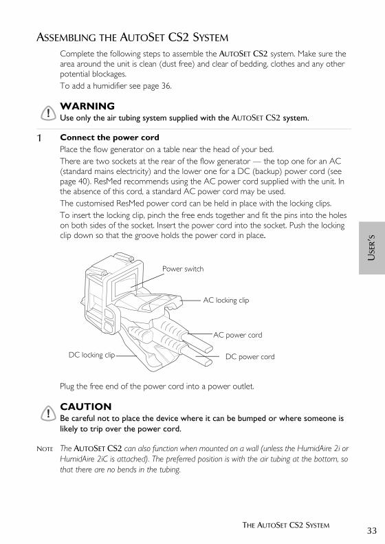
Complete the following steps to assemble the AUTOSET CS2 system. Make sure the area around the unit is clean (dust free) and clear of bedding, clothes and any other potential blockages. To add a humidifier see page 36.
!WARNINGUse only the air tubing system supplied with the AUTOSET CS2 system.
1 Connect the power cordPlace the flow generator on a table near the head of your bed. There are two sockets at the rear of the flow generator — the top one for an AC (standard mains electricity) and the lower one for a DC (backup) power cord (see page 40). ResMed recommends using the AC power cord supplied with the unit. In the absence of this cord, a standard AC power cord may be used.The customised ResMed power cord can be held in place with the locking clips.To insert the locking clip, pinch the free ends together and fit the pins into the holes on both sides of the socket. Insert the power cord into the socket. Push the locking clip down so that the groove holds the power cord in place.
Plug the free end of the power cord into a power outlet.
!CAUTIONBe careful not to place the device where it can be bumped or where someone is likely to trip over the power cord.
NOTE The AUTOSET CS2 can also function when mounted on a wall (unless the HumidAire 2i or HumidAire 2iC is attached). The preferred position is with the air tubing at the bottom, so that there are no bends in the tubing.
Power switch
AC locking clip
DC locking clip
AC power cord
DC power cord
26853r2eng.book Page 33 Wednesday, October 14, 2015 4:08 PM

34
2 Connect air tubing Connect the air tube firmly onto the air outlet at the front of the unit.
Figure 4: Front view of AutoSet CS2
To attach the pressure sensor tube to the unit, screw the Luer connector onto the socket on the side of the unit.
Figure 5: Twisting the Luer lock connectors together
!WARNINGUse care when handling the air tubing. Be particularly careful when attaching the Luer connector to the AUTOSET CS2. If you kink or excessively twist the sensor tube, it may affect the protection offered by the mask pressure alarm system.
Air tubing connector
Pressure sensor tube connector
26853r2eng.book Page 34 Wednesday, October 14, 2015 4:08 PM
35THE AUTOSET CS2 SYSTEM
USE
R’S
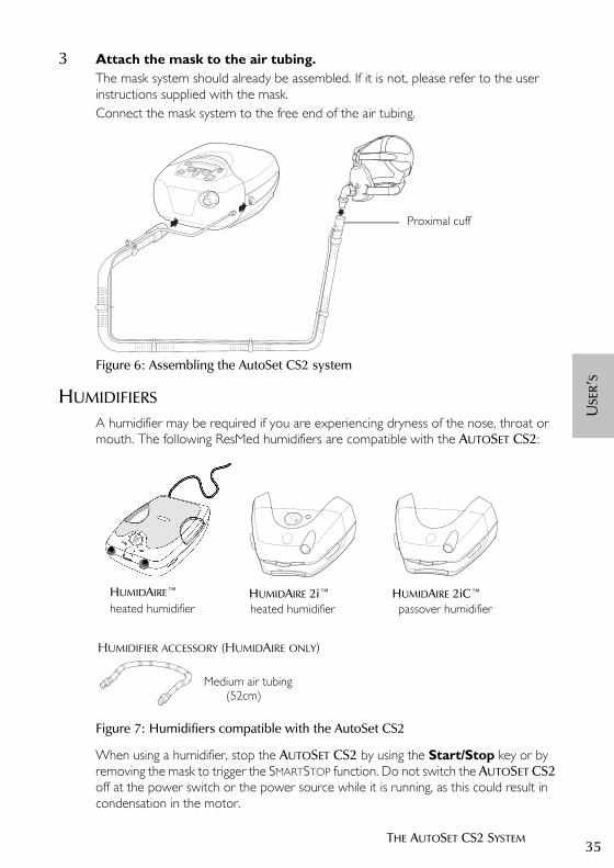
3 Attach the mask to the air tubing.The mask system should already be assembled. If it is not, please refer to the user instructions supplied with the mask. Connect the mask system to the free end of the air tubing.
Figure 6: Assembling the AutoSet CS2 system
HUMIDIFIERS
A humidifier may be required if you are experiencing dryness of the nose, throat or mouth. The following ResMed humidifiers are compatible with the AUTOSET CS2:
Figure 7: Humidifiers compatible with the AutoSet CS2
When using a humidifier, stop the AUTOSET CS2 by using the Start/Stop key or by removing the mask to trigger the SMARTSTOP function. Do not switch the AUTOSET CS2 off at the power switch or the power source while it is running, as this could result in condensation in the motor.
Proximal cuff
HUMIDAIRE 2i™
HUMIDAIRE 2iC™
heated humidifier passover humidifier
Medium air tubing(52cm)
HUMIDIFIER ACCESSORY (HUMIDAIRE ONLY)
HUMIDAIRE™
heated humidifier
26853r2eng.book Page 35 Wednesday, October 14, 2015 4:08 PM
36
CONNECTING A HUMIDIFIER
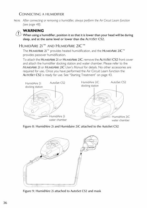
NOTE After connecting or removing a humidifier, always perform the Air Circuit Learn function (see page 48).
!WARNINGWhen using a humidifier, position it so that it is lower than your head will be during sleep, and at the same level or lower than the AUTOSET CS2.
HUMIDAIRE 2i™ AND HUMIDAIRE 2iC™The HUMIDAIRE 2i™ provides heated humidification, and the HUMIDAIRE 2iC™ provides passover humidification.To attach the HUMIDAIRE 2i or HUMIDAIRE 2iC, remove the AUTOSET CS2 front cover and attach the humidifier docking station and water chamber. Please refer to the HUMIDAIRE 2i or HUMIDAIRE 2iC User’s Manual for details. No other accessories are required for use. Once you have performed the Air Circuit Learn function the AUTOSET CS2 is ready for use. See “Starting Treatment” on page 43.
Figure 8: HumidAire 2i and Humidaire 2iC attached to the AutoSet CS2
Figure 9: HumidAire 2i attached to AutoSet CS2 and mask
AutoSet CS2HumidAire 2i
water chamber
docking station
HumidAire 2i
HumidAire 2iC docking station
water chamberHumidAire 2iC
AutoSet CS2
26853r2eng.book Page 36 Wednesday, October 14, 2015 4:08 PM

37THE AUTOSET CS2 SYSTEM
USE
R’S
HUMIDAIRE
You will need a Medium size (52cm) air tube to connect the AUTOSET CS2 unit to the HUMIDAIRE™ (see Figure 7).
1 Make sure both the HUMIDAIRE and the AUTOSET CS2 are turned off. Fill the HUMIDAIRE with water as described in the humidifier manual. Place the filled water chamber inside the HUMIDAIRE.
2 Gently detach enough of the tube clips to release the end of the pressure sensor tube from the AUTOSET CS2 air tubing. Connect the AUTOSET CS2 air tubing to the left connector port on the humidifier, and the medium (52cm) air tubing to the right connector port. Close the HUMIDAIRE lid.
3 Place the AUTOSET CS2 on top of the HUMIDAIRE. Do not place the AUTOSET CS2 unit underneath the humidifier. (This is to avoid water spilling into the unit.)
HumidAire
Medium air tubing
AutoSet CS2 air tubingPressure sensor tube
26853r2eng.book Page 37 Wednesday, October 14, 2015 4:08 PM
38
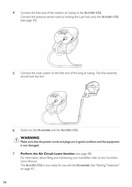
4 Connect the free end of the medium air tubing to the AUTOSET CS2.Connect the pressure sensor tube by twisting the Luer lock onto the AUTOSET CS2 (see page 34).
5 Connect the mask system to the free end of the long air tubing. The final assembly should look like this:
6 Switch on the HUMIDAIRE and the AUTOSET CS2.
!WARNINGMake sure that the power cords and plugs are in good condition and the equipment is not damaged.
7 Perform the Air Circuit Learn function (see page 48).For information about filling and maintaining your humidifier, refer to the HumidAire User’s Manual.The AUTOSET CS2 is now ready for use with the HUMIDAIRE. See “Starting Treatment” on page 43.
26853r2eng.book Page 38 Wednesday, October 14, 2015 4:08 PM
39THE AUTOSET CS2 SYSTEM
USE
R’S
!CAUTION• Be very careful not to allow water to enter the AUTOSET CS2 as this
could affect therapy and/or damage the device.• Do not tip the HUMIDAIRE while it is connected to the AUTOSET CS2.
If water enters the AUTOSET CS2 device, turn off the main power switch at the back of the unit and unplug it from the power outlet. Return the unit to your equipment supplier for checking.
• Set up the HUMIDAIRE and the AUTOSET CS2 unit so that the tubing to the mask runs higher than the machines. This will prevent condensation build-up.
• If condensation appears in the mask, turn the humidifier settings down.
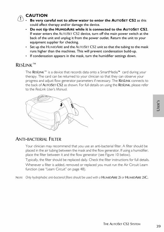
RESLINK™The RESLINK™ is a device that records data onto a SmartMedia™ card during your therapy. The card can be returned to your clinician so that they can observe your progress and adjust flow generator parameters if necessary. The RESLINK connects to the back of AUTOSET CS2 as shown. For full details on using the RESLINK, please refer to the ResLink User’s Manual.
ANTI-BACTERIAL FILTER
Your clinician may recommend that you use an anti-bacterial filter. A filter should be placed in the air tubing between the mask and the flow generator. If using a humidifier, place the filter between it and the flow generator (see Figure 10 below).Typically, the filter should be replaced daily. Check the filter instructions for full details.Whenever a filter is added, removed or replaced you must run the Air Circuit Learn function (see “Learn Circuit” on page 48).
NOTE Only hydrophobic anti-bacterial filters should be used with a HUMIDAIRE 2i or HUMIDAIRE 2iC.
26853r2eng.book Page 39 Wednesday, October 14, 2015 4:08 PM
40
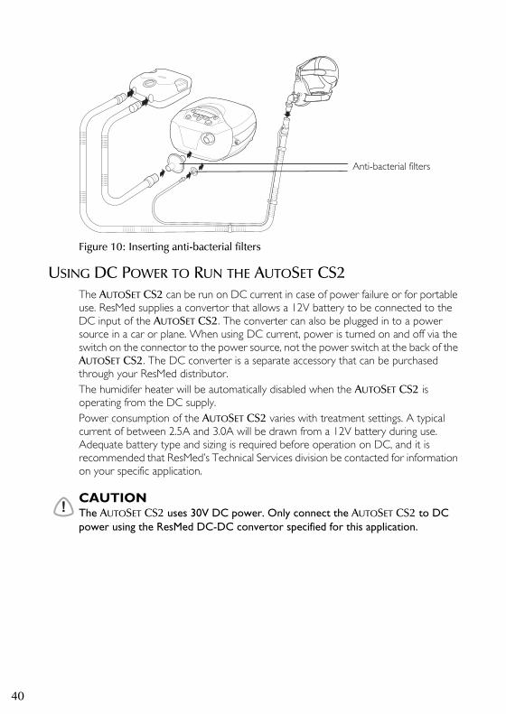
Figure 10: Inserting anti-bacterial filters
USING DC POWER TO RUN THE AUTOSET CS2The AUTOSET CS2 can be run on DC current in case of power failure or for portable use. ResMed supplies a convertor that allows a 12V battery to be connected to the DC input of the AUTOSET CS2. The converter can also be plugged in to a power source in a car or plane. When using DC current, power is turned on and off via the switch on the connector to the power source, not the power switch at the back of the AUTOSET CS2. The DC converter is a separate accessory that can be purchased through your ResMed distributor.The humidifer heater will be automatically disabled when the AUTOSET CS2 is operating from the DC supply. Power consumption of the AUTOSET CS2 varies with treatment settings. A typical current of between 2.5A and 3.0A will be drawn from a 12V battery during use. Adequate battery type and sizing is required before operation on DC, and it is recommended that ResMed’s Technical Services division be contacted for information on your specific application.
!CAUTIONThe AUTOSET CS2 uses 30V DC power. Only connect the AUTOSET CS2 to DC power using the ResMed DC-DC convertor specified for this application.
Anti-bacterial filters
26853r2eng.book Page 40 Wednesday, October 14, 2015 4:08 PM

41THE AUTOSET CS2 SYSTEM
USE
R’S
USING SUPPLEMENTAL OXYGEN
If oxygen is being added at the mask, the oxygen tube is attached to the mask port. Refer to your mask manual for full instructions.Up to 15 L/min of oxygen can be added at the mask when using an AUTOSET CS2 system.
Figure 11: Oxygen tube attached to Mirage FFMS2 and Ultra Mirage masks
!WARNINGS• If oxygen is used with this device, the oxygen flow must be turned off when the
device is not operating. Explanation: When the device is not in operation, and the oxygen flow is left on, oxygen delivered into the ventilator tubing may accumulate within the device enclosure and create a risk of fire.
• Always begin AUTOSET CS2 therapy before the oxygen supply is turned on.• Always turn the oxygen supply off before stopping AUTOSET CS2 therapy.• Oxygen supports combustion. Oxygen should not be used while smoking or in
the presence of an open flame.
Oxygen tubeOxygen tube
26853r2eng.book Page 41 Wednesday, October 14, 2015 4:08 PM

42
26853r2eng.book Page 42 Wednesday, October 14, 2015 4:08 PM
43USING THE AUTOSET CS2
USE
R’S
USING THE AUTOSET CS2
!WARNINGBefore starting therapy with a new mask, select the correct mask type in the Settings menu (page 48). When adding or removing a new component such as a mask, humidifier or anti-bacterial filter, perform the Air Circuit Learn function (page 48).
STARTING TREATMENT
When the system is fully assembled, press the power switch at the back of the AUTOSET CS2 to ON. The Welcome screen will be displayed while the flow generator is warming up. Allow the unit to warm up for approximately 30 seconds before placing the mask on your face.
Figure 12: Welcome screen
Once the AUTOSET CS2 has warmed up, breathing into the mask should start therapy immediately. If not, press the Start/Stop key once to commence treatment.The AUTOSET CS2 restarts in the mode in which it stopped.
STOPPING TREATMENT
If SMARTSTOP is enabled, treatment will stop automatically when you remove your mask. If the SMARTSTOP function has been disabled, press the Start/Stop key.
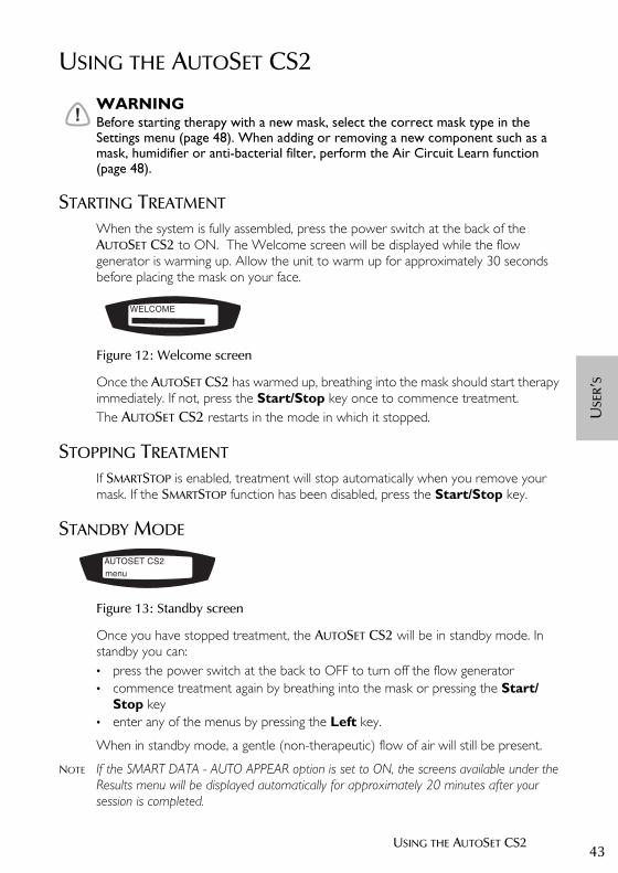
STANDBY MODE
Figure 13: Standby screen
Once you have stopped treatment, the AUTOSET CS2 will be in standby mode. In standby you can: • press the power switch at the back to OFF to turn off the flow generator• commence treatment again by breathing into the mask or pressing the Start/
Stop key• enter any of the menus by pressing the Left key.
When in standby mode, a gentle (non-therapeutic) flow of air will still be present.
NOTE If the SMART DATA - AUTO APPEAR option is set to ON, the screens available under the Results menu will be displayed automatically for approximately 20 minutes after your session is completed.
WELCOME
AUTOSET CS2menu
26853r2eng.book Page 43 Wednesday, October 14, 2015 4:08 PM

44
CONTROL PANEL FUNCTIONS
The control panel of the AUTOSET CS2 has a keypad that allows you to: • start or stop treatment• adjust settings on the flow generator• mute or stop alarms• view treatment data.
Figure 14: The AutoSet CS2 control panel
LCD SCREENDisplays information about flow generator settings, alarms and treatment. The LCD screen is backlit whenever any key is pressed. The lighting will turn off automatically when no button has been pressed for 2 minutes, or can be set to stay on (see “Options menu” on page 50). An alarm message will overwrite any other message on the screen. The original screen will reappear when any key is pressed.
START/STOP KEY• Press the key once to start or stop treatment.
UP/DOWN KEY• Moves backwards and forwards within a menu and between menus.• Increases and decreases values of parameters — press once to adjust in single
increments; hold down to move quickly through the values.
LCD display
Alarm LEDs
Alarm mute key
Left Up/Down Start/Stop
QuickView key
key keykeyRight key
26853r2eng.book Page 44 Wednesday, October 14, 2015 4:08 PM

45USING THE AUTOSET CS2
USE
R’S
LEFT KEY (GREEN)• Enters a menu.• Confirms and applies settings.• Performs the function indicated by the text above it in the LCD (eg ’enter’, ’change’).
RIGHT KEY (RED)• Performs the function indicated by the text above it in the LCD (eg ’exit’).• Cancels operations.• Extended hold: exits to the top level of the menu.
QUICKVIEW KEYTakes you immediately to the Treatment screens, with information on your current therapy. See “Treatment Screens” on page 51.
ALARM LEDS AND ALARM MUTEThe Alarm LEDs are lights that indicate that an alarm has been triggered. Alarms can be muted by pressing the Alarm mute key once. The Alarm LEDs will remain lit for as long as the alarm is being triggered. See “The Alarms” on page 53.
ADJUSTING SETTINGS
By using the Left, Right and Up/Down keys you can adjust some aspects of your treatment. The settings can be seen in the LCD display.The settings are arranged into five menus:
Table 1: Menus and adjustments for AutoSet CS2
* These menus appear only if at least one Smart Data option has been enabled by the clinician.
To change a setting, press the Up/Down key until you arrive at the menu you require. • Press the Left key to enter the menu, then use the Up/Down key again to scroll
through the options.
Settings Alarms Results* Options Servicing
Ramp (CPAP mode only): change time
Sound level: LOW, MED, HIGH
Mask fit Smart data:Auto appear—on/off*
SN (serial number)
Mask type: change type
LOW PS Average Pressure Backlight: Auto/on
PCB (printed circuit board)
Learn circuit: run Usage Language: English/ French/ German/Italian/Spanish/Swedish/Portuguese/Dutch
SW (software version)
SmartStop: off/on
Leak alert: off/on
26853r2eng.book Page 45 Wednesday, October 14, 2015 4:08 PM
46
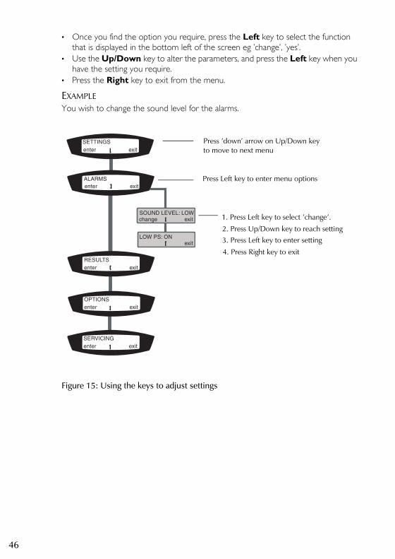
• Once you find the option you require, press the Left key to select the function that is displayed in the bottom left of the screen eg ’change’, ’yes’.
• Use the Up/Down key to alter the parameters, and press the Left key when you have the setting you require.
• Press the Right key to exit from the menu.
EXAMPLEYou wish to change the sound level for the alarms.
Figure 15: Using the keys to adjust settings
SETTINGS
enter exit
RESULTSenter exit
OPTIONSenter exit
SOUND LEVEL: LOW
enter exit
ALARMS
change exit
SERVICINGenter exit
LOW PS: ON exit
Press ’down’ arrow on Up/Down key
Press Left key to enter menu options
1. Press Left key to select ’change’.
2. Press Up/Down key to reach setting3. Press Left key to enter setting
4. Press Right key to exit
to move to next menu
26853r2eng.book Page 46 Wednesday, October 14, 2015 4:08 PM

47USING THE AUTOSET CS2
USE
R’S
MENUSThe options available in the Settings menu will depend on the therapy you are receiving, set by your clinician.
Figure 16: Navigating the Patient menu.
LOW PS:ON
AVG PRESS: 10.4
SW: SX245-0117
These menus appearonly if at least oneSmart Data optionhas been enabled bythe clinician.
26853r2eng.book Page 47 Wednesday, October 14, 2015 4:08 PM
48
SETTINGS MENUYou will only see the options relevant to your therapy. In CPAP (Continuous Positive Airway Pressure) mode, the clinician sets a pressure that will be constant throughout treatment. In ASV-CS mode, AUTOSET CS2 continually measures your breathing and regulates the air pressure accordingly.
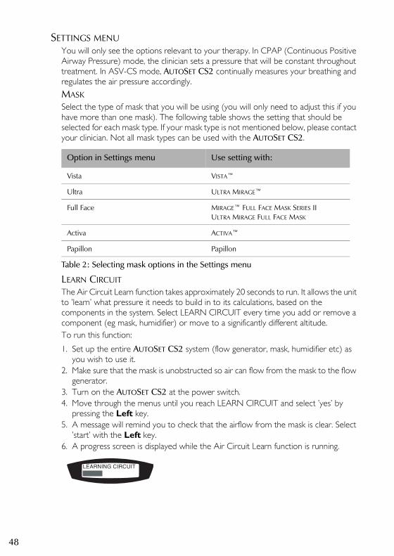
MASKSelect the type of mask that you will be using (you will only need to adjust this if you have more than one mask). The following table shows the setting that should be selected for each mask type. If your mask type is not mentioned below, please contact your clinician. Not all mask types can be used with the AUTOSET CS2.
Table 2: Selecting mask options in the Settings menu
LEARN CIRCUITThe Air Circuit Learn function takes approximately 20 seconds to run. It allows the unit to ’learn’ what pressure it needs to build in to its calculations, based on the components in the system. Select LEARN CIRCUIT every time you add or remove a component (eg mask, humidifier) or move to a significantly different altitude. To run this function:
1. Set up the entire AUTOSET CS2 system (flow generator, mask, humidifier etc) as you wish to use it.
2. Make sure that the mask is unobstructed so air can flow from the mask to the flow generator.
3. Turn on the AUTOSET CS2 at the power switch. 4. Move through the menus until you reach LEARN CIRCUIT and select ’yes’ by
pressing the Left key. 5. A message will remind you to check that the airflow from the mask is clear. Select
’start’ with the Left key.6. A progress screen is displayed while the Air Circuit Learn function is running.
Option in Settings menu Use setting with:
Vista VISTA™
Ultra ULTRA MIRAGE™
Full Face MIRAGE™ FULL FACE MASK SERIES IIULTRA MIRAGE FULL FACE MASK
Activa ACTIVA™
Papillon Papillon
LEARNING CIRCUIT
26853r2eng.book Page 48 Wednesday, October 14, 2015 4:08 PM
49USING THE AUTOSET CS2
USE
R’S
7. When the function is complete, a screen will appear saying that the circuit has been learned successfully. The next menu item is then displayed. Commence treatment as described in “Starting Treatment” on page 43.
If there is a problem with the circuit, a screen saying ’Invalid circuit’ will be displayed instead of the progress screen. Check that all the connections between the pieces of equipment are secure. You may need to return to the previous chapter of this manual to check that you have set up the system correctly.
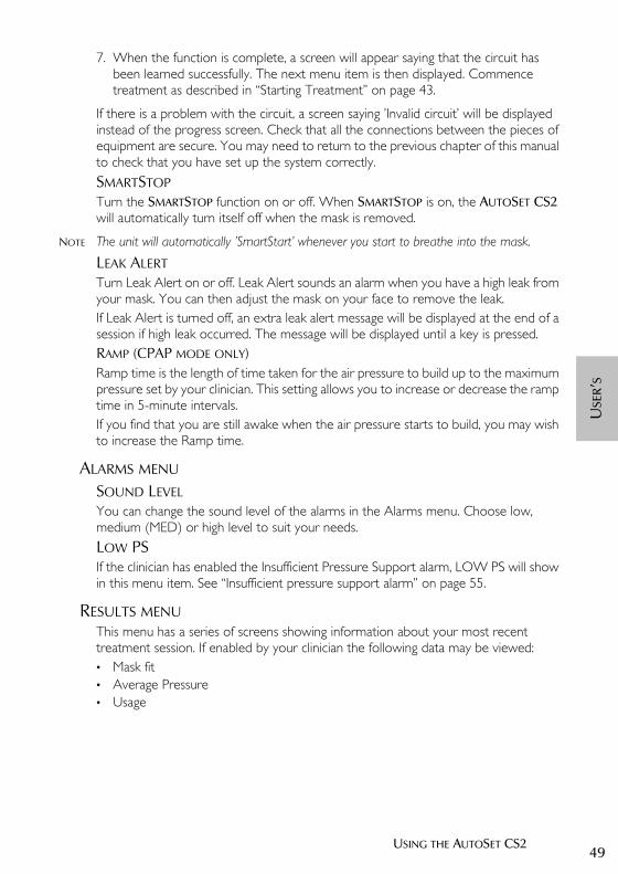
SMARTSTOPTurn the SMARTSTOP function on or off. When SMARTSTOP is on, the AUTOSET CS2 will automatically turn itself off when the mask is removed.
NOTE The unit will automatically ’SmartStart’ whenever you start to breathe into the mask.
LEAK ALERTTurn Leak Alert on or off. Leak Alert sounds an alarm when you have a high leak from your mask. You can then adjust the mask on your face to remove the leak. If Leak Alert is turned off, an extra leak alert message will be displayed at the end of a session if high leak occurred. The message will be displayed until a key is pressed.RAMP (CPAP MODE ONLY)Ramp time is the length of time taken for the air pressure to build up to the maximum pressure set by your clinician. This setting allows you to increase or decrease the ramp time in 5-minute intervals.If you find that you are still awake when the air pressure starts to build, you may wish to increase the Ramp time.
ALARMS MENU
SOUND LEVELYou can change the sound level of the alarms in the Alarms menu. Choose low, medium (MED) or high level to suit your needs.
LOW PSIf the clinician has enabled the Insufficient Pressure Support alarm, LOW PS will show in this menu item. See “Insufficient pressure support alarm” on page 55.
RESULTS MENUThis menu has a series of screens showing information about your most recent treatment session. If enabled by your clinician the following data may be viewed:• Mask fit• Average Pressure• Usage
26853r2eng.book Page 49 Wednesday, October 14, 2015 4:08 PM

50
MASK FITGives a rating of how well the mask was fitting during your last session on the AUTOSET CS2. The stars indicate how good the fit was (more stars = better fit).
AVERAGE PRESSUREProvides information on the average air pressure during your most recent session on the AUTOSET CS2. USAGETells you how long the AUTOSET CS2 was in use during your most recent session.
OPTIONS MENUThe Options menu allows you to change:• Smart Data (Auto Appear)• Backlight• Language
SMART DATAIf the SMART DATA - AUTO APPEAR option is set to ON, the screens available under the Results menu will be displayed automatically for approximately 20 minutes after your session is completed. After this time the data will still be available in the Results menu. If you want to turn off AUTO APPEAR, select ’enter’ in the SMART DATA screen by pressing the Left key. The AUTO APPEAR screen will be displayed. Select ’change’ by pressing the Left key and you will switch from ON to OFF (similarly, you can turn it from OFF to ON). Your clinician may also turn off AUTO APPEAR.
BACKLIGHTOn: Display a permanent backlight for the LCD.Auto: Backlight turns off if no button has been pressed for two minutes.
LANGUAGEChange the language of the LCD display. Languages available are: English, French, German, Italian, Spanish, Portuguese, Swedish, Dutch.
Star rating Definition
***** Excellent
∗∗∗∗− Very good
∗∗∗−− Good
∗∗−−− Adjust mask
∗−−−− Adjust mask
HIGH LEAK Adjust mask
26853r2eng.book Page 50 Wednesday, October 14, 2015 4:08 PM
51USING THE AUTOSET CS2
USE
R’S
SERVICING MENUThis menu displays the following information:• SN – the flow generator’s serial number• PCB – the flow generator’s PCB number (PCB — printed circuit board)• SW – the version of software currently installed on the flow generator.
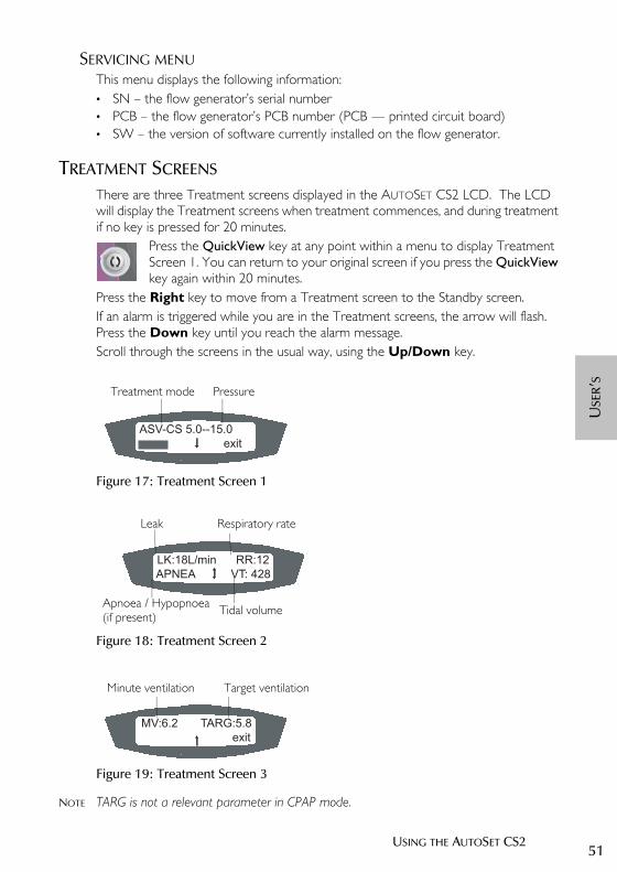
TREATMENT SCREENS
There are three Treatment screens displayed in the AUTOSET CS2 LCD. The LCD will display the Treatment screens when treatment commences, and during treatment if no key is pressed for 20 minutes.
Press the QuickView key at any point within a menu to display Treatment Screen 1. You can return to your original screen if you press the QuickView key again within 20 minutes.
Press the Right key to move from a Treatment screen to the Standby screen.If an alarm is triggered while you are in the Treatment screens, the arrow will flash. Press the Down key until you reach the alarm message.Scroll through the screens in the usual way, using the Up/Down key.
Figure 17: Treatment Screen 1
Figure 18: Treatment Screen 2
Figure 19: Treatment Screen 3
NOTE TARG is not a relevant parameter in CPAP mode.
ASV-CS 5.0--15.0
exit
Treatment mode Pressure
LK:18L/min RR:12
APNEA VT: 428
Leak Respiratory rate
Apnoea / Hypopnoea Tidal volume(if present)
MV:6.2 TARG:5.8
exit
Minute ventilation Target ventilation
26853r2eng.book Page 51 Wednesday, October 14, 2015 4:08 PM

52
26853r2eng.book Page 52 Wednesday, October 14, 2015 4:08 PM
53THE ALARMS
USE
R’S
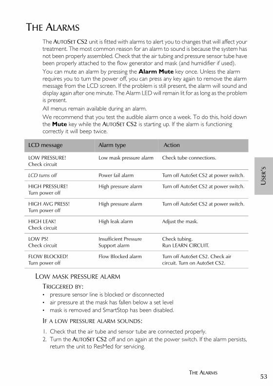
THE ALARMSThe AUTOSET CS2 unit is fitted with alarms to alert you to changes that will affect your treatment. The most common reason for an alarm to sound is because the system has not been properly assembled. Check that the air tubing and pressure sensor tube have been properly attached to the flow generator and mask (and humidifier if used).You can mute an alarm by pressing the Alarm Mute key once. Unless the alarm requires you to turn the power off, you can press any key again to remove the alarm message from the LCD screen. If the problem is still present, the alarm will sound and display again after one minute. The Alarm LED will remain lit for as long as the problem is present.All menus remain available during an alarm.We recommend that you test the audible alarm once a week. To do this, hold down the Mute key while the AUTOSET CS2 is starting up. If the alarm is functioning correctly it will beep twice.
LOW MASK PRESSURE ALARM
TRIGGERED BY: • pressure sensor line is blocked or disconnected• air pressure at the mask has fallen below a set level• mask is removed and SmartStop has been disabled.
IF A LOW PRESSURE ALARM SOUNDS:1. Check that the air tube and sensor tube are connected properly.2. Turn the AUTOSET CS2 off and on again at the power switch. If the alarm persists,
return the unit to ResMed for servicing.
LCD message Alarm type Action
LOW PRESSURE!Check circuit
Low mask pressure alarm Check tube connections.
LCD turns off Power fail alarm Turn off AutoSet CS2 at power switch.
HIGH PRESSURE!Turn power off
High pressure alarm Turn off AutoSet CS2 at power switch.
HIGH AVG PRESS!Turn power off
High pressure alarm Turn off AutoSet CS2 at power switch.
HIGH LEAK!Check circuit
High leak alarm Adjust the mask.
LOW PS!Check circuit
Insufficient Pressure Support alarm
Check tubing.Run LEARN CIRCUIT.
FLOW BLOCKED!Turn power off
Flow Blocked alarm Turn off AutoSet CS2. Check air circuit. Turn on AutoSet CS2.
26853r2eng.book Page 53 Wednesday, October 14, 2015 4:08 PM

54
WILL CLEAR WHEN:• the low pressure condition is fixed• treatment is stopped by pressing the Start/Stop key.
POWER FAIL ALARM
TRIGGERED BY: • power failure• machine is disconnected or switched off while delivering treatment.
IF A POWER FAIL ALARM SOUNDS:• The flow generator stops delivering air pressure.
WILL STOP:• when the Alarm Mute key is pressed, or• after 2 minutes, or• when power is restored.
!CAUTIONRemove the mask from your face if the power fails.
HIGH PRESSURE ALARM
TRIGGERED BY: • the mask pressure exceeds the set trigger level (25 cmH2O) for more than 700
milliseconds.
IF A HIGH PRESSURE ALARM SOUNDS:1. The treatment will stop.2. Turn power off.3. Check that the air tube and sensor tubes are connected properly.4. Turn power back on.5. Remove mask and perform Air Circuit Learn function.6. Try using the flow generator one more time.7. If the high pressure alarm activates repeatedly, discontinue use and return to
ResMed for servicing. If the alarm does not recur, then continue to use as normal.
NOTE The alarm system is designed to ignore coughing. However, if a cough is especially intense and prolonged, it may trigger the high pressure alarm.
WILL STOP WHEN:• the AUTOSET CS2 is turned off.
HIGH LEAK ALARM
TRIGGERED BY: • high mask leak (greater than 30 L/min) for more than 20 seconds.
IF A HIGH LEAK ALARM SOUNDS:• Adjust the mask to minimise leak.
26853r2eng.book Page 54 Wednesday, October 14, 2015 4:08 PM
55THE ALARMS
USE
R’S
WILL STOP WHEN:• the mask leak has been rectified.
NOTE The High Leak alarm can be turned off in the Leak Alert option in the Settings menu.
INSUFFICIENT PRESSURE SUPPORT ALARM
TRIGGERED BY: • air pressure at the mask has failed to reach an expected level for 3 breaths• the Air Circuit Learn function (page 48) has not been run after adding a new
component (eg new mask, humidifier) to the system.
IF AN INSUFFICIENT PRESSURE SUPPORT ALARM SOUNDS:• check that the pressure sensor tubing is not kinked• check that the pressure sensor tubing is properly connected• run LEARN CIRCUIT.
WILL STOP WHEN:• the pressure sensor tubing is unobstructed and properly connected to the flow
generator and mask• treatment is stopped (Start/Stop key or SMARTSTOP)• the AUTOSET CS2 is turned off.
FLOW BLOCKED ALARM
TRIGGERED BY: • blockage in air circuit
IF A FLOW BLOCKED ALARM SOUNDS:1. The treatment will stop.2. Turn power off.3. Check whether there is a blockage in the air circuit.4. Remove blockage.5. Turn power back on.6. If the Flow blocked alarm activates repeatedly, discontinue use and return to
ResMed for servicing. If the alarm does not recur, then continue to use as normal.
WILL STOP WHEN:• blockage is removed.
26853r2eng.book Page 55 Wednesday, October 14, 2015 4:08 PM

56
26853r2eng.book Page 56 Wednesday, October 14, 2015 4:08 PM
57CLEANING AND MAINTENANCE
USE
R’S
CLEANING AND MAINTENANCEYou should regularly carry out the cleaning and maintenance described in this manual.
!CAUTIONDo not wash the pressure sensor tube. If fluid enters the pressure sensor tube allow it to dry completely by hanging it in a clean place out of direct sunlight. If the pressure sensor tube cannot be dried completely it should be replaced.
DAILY
1. Disconnect the air tubing and pressure sensor tube and hang them in a clean, dry place until next use. Do not hang the air tubing in direct sunlight as it may harden and crack over time.
2. Clean the mask according to the mask user instructions.3. If you are using a humidifier, clean it according to the instructions in the manual.
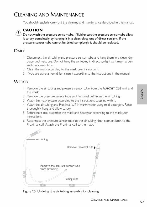
WEEKLY
1. Remove the air tubing and pressure sensor tube from the AUTOSET CS2 unit and the mask.
2. Remove the pressure sensor tube and Proximal cuff from the air tubing.3. Wash the mask system according to the instructions supplied with it. 4. Wash the air tubing and Proximal cuff in warm water using mild detergent. Rinse
thoroughly, hang and allow to dry.5. Before next use, assemble the mask and headgear according to the mask user
instructions. 6. Reconnect the pressure sensor tube to the air tubing, then connect both to the
Proximal cuff. Attach the Proximal cuff to the mask.
Figure 20: Undoing the air tubing assembly for cleaning
Tubing clips
Remove the pressure sensor tube
Air tubing
Remove Proximal cuff
from air tubing
26853r2eng.book Page 57 Wednesday, October 14, 2015 4:08 PM
58
!CAUTION• Do not use bleach, chlorine-, alcohol- or aromatic-based solutions (including all
scented oils), moisturising or antibacterial soaps to clean the cushion, mask, air tubing or the AUTOSET CS2. These solutions may cause hardening and reduce the life of the product.
• Do not wash or dry the mask frame at a temperature above 80oC (176oF). Exposure to higher temperatures may reduce the life of the product.
• Do not hang the air tubing and pressure sensor tube in direct sunlight as the tubing may harden over time and eventually crack.
PERIODICALLY
1. The mask and air tubing are subject to normal wear and tear. Inspect them regularly for damage.
2. Open the power cord locking clip and remove the cord. Clean the exterior of the flow generator with a damp cloth and mild detergent.
3. Inspect the air filter to check if it is blocked by dirt or contains holes. See full instructions below.
!WARNINGBeware of electric shock. Do not immerse the flow generator or power cord in water. Always unplug the flow generator before cleaning and be sure that it is dry before reconnecting.
!CAUTIONDo not attempt to open the AUTOSET CS2. There are no user serviceable parts inside. Repairs and internal servicing should only be performed by an authorised service agent.
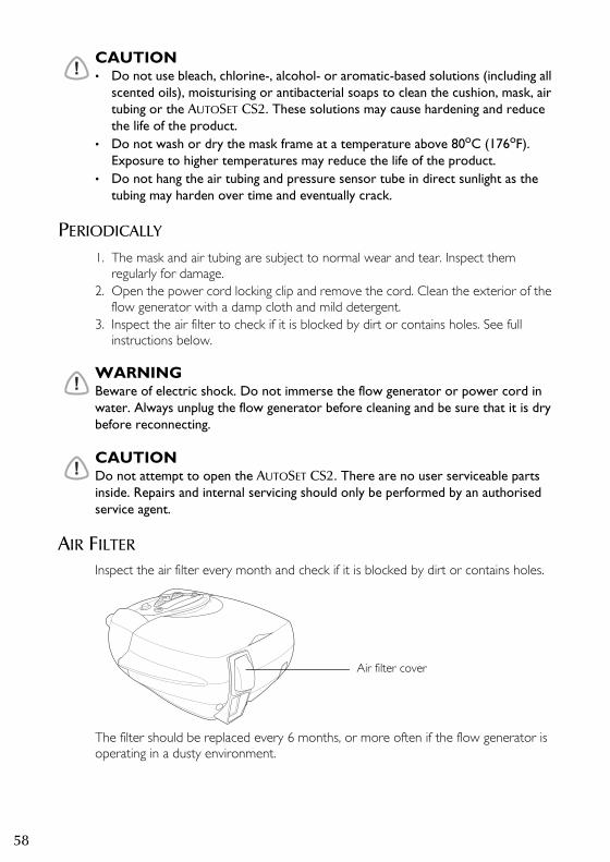
AIR FILTER
Inspect the air filter every month and check if it is blocked by dirt or contains holes.
The filter should be replaced every 6 months, or more often if the flow generator is operating in a dusty environment.
Air filter cover
26853r2eng.book Page 58 Wednesday, October 14, 2015 4:08 PM

59CLEANING AND MAINTENANCE
USE
R’S
!WARNINGDo not wash the air filter once it has become soiled. The air filter is not washable or reusable.
FITTING THE FILTER• Remove the filter cover at the back of the flow generator.• Remove and discard the old air filter.• Insert a new filter, the blue tinted side facing towards you.
NOTE Match the cut corner of the filter with the shape of the casing.• Replace the air filter cover. The blue tinted side of the filter should be facing out.
HYPOALLERGENIC AIR FILTERThe ResMed hypo-allergenic filter is a standard filter to which an electrostatic filter has been bonded to capture very small particles. The filter is intended for those users of ResMed flow generators who will benefit from enhanced filtering of the air delivered during treatment.Inspect the air filter every month and check if it is blocked by dirt or contains holes.The filter should be replaced every three months, or more often if the flow generator is operating in a dusty environment.Fit as described above.
26853r2eng.book Page 59 Wednesday, October 14, 2015 4:08 PM

60
26853r2eng.book Page 60 Wednesday, October 14, 2015 4:08 PM

61TROUBLESHOOTING
USE
R’S
TROUBLESHOOTINGIf there is a problem, try the following suggestions. If the problem cannot be solved, contact your equipment supplier or ResMed. Do not attempt to open the flow generator.
Problem Possible cause Solution
Insufficient air delivered from flow generator
Air filter is dirty. Replace air filter.
Air tubing is kinked or punctured.
Straighten or replace tubing.
Flow generator operating erratically, ie, switching on and off, pressure varying at random
Water may have entered the air tubing.
Remove the water from the air tubing.
Pressure rises inappropriately You are talking, coughing, voluntarily breath-holding (eg while rolling over in bed), or intentionally breathing in an unusual manner.
Avoid talking with the mask on, and breathe as normally as possible.
Severe mask leak or mouth leak (greater than 30 L/min).
Correct your leak condition.
Alarm stays on continuously Blockage in air circuit. Ensure there is no barrier to the passage of air.
Internal malfunction. Return the device to your equipment supplier for service.
No LCD display Power not connected or switch at back is not on.
Ensure the power cable is connected, and that the switch at the back of the unit is in the “on” position.
FAULT message displayed on LCD
Internal malfunction. Return the device to your equipment supplier for service.
System Error 7 message Device power-on has been interrupted by breathing into the mask during warm up.
Turn the flow generator off and on again. Do not place mask on face during warm up (30 seconds). Select LEARN CIRCUIT (page 48). If the error is not cleared, contact your equipment supplier for service.
Internal malfunction. Return the device to your equipment supplier for service.
26853r2eng.book Page 61 Wednesday, October 14, 2015 4:08 PM

62
26853r2eng.book Page 62 Wednesday, October 14, 2015 4:08 PM

63GLOSSARY
USE
R’S
GLOSSARYAlarms: When more than one alarm is activated at the one time, the highest priority alarm will be displayed.Backlight: The backlight turns off if no button has been pressed for two minutes. It can also be kept permanently on by selecting On in the Backlight screen of the Options menu.bpm: breaths per minuteL/min: litres per minuteMean: The average value of the monitored parameter.Minute ventilation: A measure of the respiratory rate x tidal volume.Proximal cuff: A connector between the air tubing and the mask. The pressure sensor tubing attaches to the Proximal cuff so that pressure at the mask can be detected and monitored.SmartStart: A feature that starts the AUTOSET CS2 automatically when you breathe into the mask.SmartStop: A feature that stops the AUTOSET CS2 automatically when you remove the mask. You can turn SmartStop on or off in the Settings menu.Tidal volume: The volume of air, in litres, breathed in or out in one breath.
26853r2eng.book Page 63 Wednesday, October 14, 2015 4:08 PM

64
26853r2eng.book Page 64 Wednesday, October 14, 2015 4:08 PM
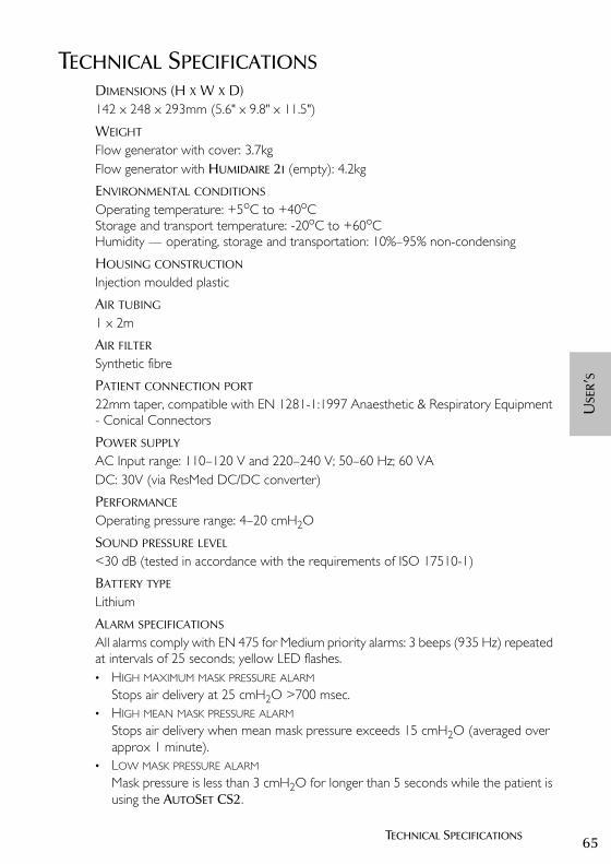
65TECHNICAL SPECIFICATIONS
USE
R’S
TECHNICAL SPECIFICATIONSDIMENSIONS (H X W X D)142 x 248 x 293mm (5.6" x 9.8" x 11.5")
WEIGHT
Flow generator with cover: 3.7kgFlow generator with HUMIDAIRE 2I (empty): 4.2kg
ENVIRONMENTAL CONDITIONS
Operating temperature: +5oC to +40oCStorage and transport temperature: -20oC to +60oCHumidity — operating, storage and transportation: 10%–95% non-condensing
HOUSING CONSTRUCTION
Injection moulded plastic
AIR TUBING
1 x 2m
AIR FILTER Synthetic fibre
PATIENT CONNECTION PORT
22mm taper, compatible with EN 1281-1:1997 Anaesthetic & Respiratory Equipment - Conical Connectors
POWER SUPPLY
AC Input range: 110–120 V and 220–240 V; 50–60 Hz; 60 VA DC: 30V (via ResMed DC/DC converter)
PERFORMANCE
Operating pressure range: 4–20 cmH2O
SOUND PRESSURE LEVEL
<30 dB (tested in accordance with the requirements of ISO 17510-1)
BATTERY TYPE
Lithium
ALARM SPECIFICATIONS
All alarms comply with EN 475 for Medium priority alarms: 3 beeps (935 Hz) repeated at intervals of 25 seconds; yellow LED flashes.• HIGH MAXIMUM MASK PRESSURE ALARM
Stops air delivery at 25 cmH2O >700 msec.• HIGH MEAN MASK PRESSURE ALARM
Stops air delivery when mean mask pressure exceeds 15 cmH2O (averaged over approx 1 minute).
• LOW MASK PRESSURE ALARM
Mask pressure is less than 3 cmH2O for longer than 5 seconds while the patient is using the AUTOSET CS2.
26853r2eng.book Page 65 Wednesday, October 14, 2015 4:08 PM
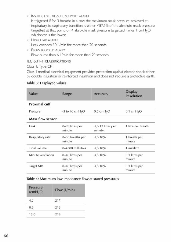
66
• INSUFFICIENT PRESSURE SUPPORT ALARM
Is triggered if for 3 breaths in a row the maximum mask pressure achieved at inspiratory to expiratory transition is either <87.5% of the absolute mask pressure targetted at that point, or < absolute mask pressure targetted minus 1 cmH2O, whichever is the lower.
• HIGH LEAK ALARM
Leak exceeds 30 L/min for more than 20 seconds.• FLOW BLOCKED ALARM
Flow is less than 6 L/min for more than 20 seconds.
IEC 601-1 CLASSIFICATIONS
Class II, Type CFClass II medical electrical equipment provides protection against electric shock either by double insulation or reinforced insulation and does not require a protective earth.
Table 3: Displayed values
Table 4: Maximum low impedance flow at stated pressures
Value Range Accuracy Display Resolution
Proximal cuff
Pressure -3 to 40 cmH2O 0.5 cmH2O 0.1 cmH2O
Mass flow sensor
Leak 0–99 litres per minute
+/- 12 litres per minute
1 litre per breath
Respiratory rate 8–30 breaths per minute
+/- 10% 1 breath per minute
Tidal volume 0–4500 millilitres +/- 10% 1 millilitre
Minute ventilation 0–40 litres per minute
+/- 10% 0.1 litres per minute
Target MV 0–40 litres per minute
+/- 10% 0.1 litres per minute
Pressure (cmH2O) Flow (L/min)
4.2 217
8.6 218
13.0 219
26853r2eng.book Page 66 Wednesday, October 14, 2015 4:08 PM

67TECHNICAL SPECIFICATIONS
USE
R’S
PRESSURE VARIATION
PRESSURE VOLUME CURVE
NOTE The manufacturer reserves the right to change these specifications without notice.
GLOSSARY OF SYMBOLS
Read this Operating Manual before using/Lire le manuel d’utilisation avant emploi
0
2
4
6
8
10
12
14
16
0 1 2 3
10BPM15BPM20BPM
Breaths
Pres
sure
(cm
H2O
)
1/3 Max Pressure
2/3 Max Pressure
Max Pressure
0
100
200
300
400
500
600
4.2 4.3 4.4 4.5 4.6 4.7
0
100
200
300
400
500
600
13 13.1 13.2 13.3 13.4
0
100
200
300
400
500
600
8.5 8.6 8.7 8.8 8.9 9
Pressure (cmH2O) Pressure (cmH2O)
Pressure (cmH2O)
Vol
ume
(mL)
Vol
ume
(mL)
Vol
ume
(mL)
1/3 Max Pressure 2/3 Max Pressure
Max Pressure10 BPM
15 BPM
20 BPM
26853r2eng.book Page 67 Wednesday, October 14, 2015 4:08 PM

68
Type CF equipment/Appareil de classe CF
AC switch
Class II
26853r2eng.book Page 68 Wednesday, October 14, 2015 4:08 PM

69TECHNICAL SPECIFICATIONS
USE
R’S
GUIDANCE AND MANUFACTURER’S DECLARATION — ELECTROMAGNETIC EMISSIONS AND IMMUNITY
Guidance and manufacturer’s declaration – electromagnetic emissions
The AutoSet CS2 is intended for use in the electromagnetic environment specified below. The customer or the user of the AutoSet CS2 should assure that it is used in such an environment.
Emissions test ComplianceElectromagnetic environment - guidance
RF emissions CISPR11 Group 1 The AutoSet CS2 uses RF energy only for its internal function. Therefore, its RF emissions are very low and are not likely to cause any interference in nearby electronic equipment.
RF emissions CISPR 11 Class B The AutoSet CS2 is suitable for use in all establishments, including domestic establishments and those directly connected to the public low-voltage network that supplies buildings used for domestic purposes.
Harmonic Emissions IEC 61000-3-2
Class A
Voltage Fluctuations/Flicker Emissions IEC 61000-3-3
Complies
Medical Electrical Equipment needs special precautions regarding EMC and needs to be installed and put into service according to EMC information provided in this document.
Warnings: The AutoSet CS2 should not be used adjacent to or stacked with other equipment.If adjacent or stacked use is necessary, the AutoSet CS2 should be observed to verify normal operation in the configuration in which it will be used.
The use of accessories (eg Humidifiers) other than those specified in this manual is not recommended. They may result in increased emissions or immunity of the AutoSet CS2.
26853r2eng.book Page 69 Wednesday, October 14, 2015 4:08 PM
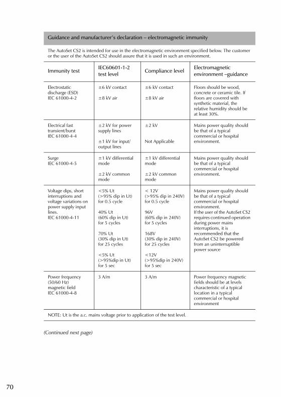
70
(Continued next page)
Guidance and manufacturer’s declaration – electromagnetic immunity
The AutoSet CS2 is intended for use in the electromagnetic environment specified below. The customer or the user of the AutoSet CS2 should assure that it is used in such an environment.
Immunity testIEC60601-1-2 test level
Compliance levelElectromagnetic environment –guidance
Electrostatic discharge (ESD)IEC 61000-4-2
±6 kV contact
±8 kV air
±6 kV contact
±8 kV air
Floors should be wood, concrete or ceramic tile. If floors are covered with synthetic material, the relative humidity should be at least 30%.
Electrical fast transient/burstIEC 61000-4-4
±2 kV for power supply lines
±1 kV for input/output lines
±2 kV
Not Applicable
Mains power quality should be that of a typical commercial or hospital environment.
SurgeIEC 61000-4-5
±1 kV differential mode ±2 kV common mode
±1 kV differential mode
±2 kV common mode
Mains power quality should be that of a typical commercial or hospital environment.
Voltage dips, short interruptions and voltage variations on power supply input lines. IEC 61000-4-11
<5% Ut (>95% dip in Ut)for 0.5 cycle
40% Ut (60% dip in Ut) for 5 cycles
70% Ut (30% dip in Ut) for 25 cycles
<5% Ut (>95%dip in Ut) for 5 sec
< 12V(>95% dip in 240V)for 0.5 cycle
96V (60% dip in 240V) for 5 cycles
168V(30% dip in 240V) for 25 cycles
<12V (>95%dip in 240V) for 5 sec
Mains power quality should be that of a typical commercial or hospital environment.If the user of the AutoSet CS2 requires continued operation during power mains interruptions, it is recommended that the AutoSet CS2 be powered from an uninterruptible power source
Power frequency (50/60 Hz) magnetic fieldIEC 61000-4-8
3 A/m 3 A/m Power frequency magnetic fields should be at levels characteristic of a typical location in a typical commercial or hospital environment
NOTE: Ut is the a.c. mains voltage prior to application of the test level.
26853r2eng.book Page 70 Wednesday, October 14, 2015 4:08 PM

71TECHNICAL SPECIFICATIONS
USE
R’S
Guidance and manufacturer’s declaration – electromagnetic immunity (continued)
The AutoSet CS2 is intended for use in the electromagnetic environment specified below. The customer or the user of the AutoSet CS2 should assure that it is used in such an environment.
Immunity test IEC60601-1-2 test level
Compliance level
Electromagnetic environment – guidance
Portable and mobile RF communications equipment should be used no closer to any part of the AutoSet CS2, including cables, than the recommended separation distance calculated from the equation applicable to the frequency of the transmitter.
Recommended separation distance
Conducted RF IEC 61000-4-6
3 Vrms 150 kHz to 80 MHz
3 Vrms d = 1.17 √P
Radiated RFIEC 61000-4-3
10 V/m80 MHz to 2.5 GHz
10 V/m d = 0.35 √P 80 MHz to 800 MHz
d = 0.70 √P 800 MHz to 2.5 GHz
where P is the maximum output power rating of the transmitter in watts (W) according to the transmitter manufacturer and d is the recommended separation distance in meters (m).Field strengths from fixed RF transmitters, as determined by an electromagnetic site survey,a should be less than the compliance level in each frequency range.b Interference may occur in the vicinity of equipment marked with the following symbol:
NOTE 1: At 80 MHz and 800MHz, the higher frequency range applies.
NOTE 2: These guidelines may not apply in all situations. Electromagnetic propagation is affected by absorption and reflection from structures, objects and people.
a Field strengths from fixed transmitters, such as base stations for radio (cellular/cordless) telephones and land mobile radios, amateur radio, AM and FM radio broadcast and TV broadcast cannot be predicted theoretically with accuracy. To assess the electromagnetic environment due to fixed RF transmitters, an electromagnetic site survey should be considered. If the measured field strength in the location in which the AutoSet CS2 is used exceeds the applicable RF compliance level above, the AutoSet CS2 should be observed to verify normal operation. If abnormal performance is observed, additional measures may be necessary, such as reorienting or relocating the AutoSet CS2.
b Over the frequency range 150 kHz to 80 MHz, field strengths should be less than 10 V/m.
26853r2eng.book Page 71 Wednesday, October 14, 2015 4:08 PM

72
Recommended separation distances between portable and mobile RF communications equipment and the AutoSet CS2
The AutoSet CS2 is intended for use in an environment in which radiated RF disturbances are controlled. The customer or the user of the AutoSet CS2 can help prevent electromagnetic interference by maintaining a minimum distance between portable and mobile RF communications equipment (transmitters) and the AutoSet CS2 as recommended below, according to the maximum output power of the communications equipment.
Separation distance according to frequency of transmitter m
Rated maximum output power of transmitter
W
150kHz to 80MHz
d = 1.17 √P
80 MHz to 800 MHz
d = 0.35 √P
800MHz to 2.5 GHz
d = 0.70 √P
0.01 0.17 0.04 0.07
0.1 0.37 0.11 0.22
1 1.17 0.35 0.70
10 3.69 1.11 2.21
100 11.70 3.50 7.00
For transmitters rated at a maximum output power not listed above, the recommended separation distance d in metres (m) can be determined using the equation applicable to the frequency of the transmitter, where P is the maximum output power rating of the transmitter in watts (W) according to the transmitter manufacturer.
NOTE 1: At 80 MHz and 800 MHz, the separation distance for the higher frequency range applies.
NOTE 2: These guidelines may not apply in all situations. Electromagnetic propagation is affected by absorption and reflection from structures, objects and people.
26853r2eng.book Page 72 Wednesday, October 14, 2015 4:08 PM

73LIMITED WARRANTY
USE
R’S
LIMITED WARRANTYResMed warrants that your ResMed product shall be free from defects in material and workmanship for the period specified below from the date of purchase by the initial consumer.
Note: Some models are not available in all regions.
If the product fails under conditions of normal use, ResMed will repair or replace, at its option, the defective product or any of its components. This Limited Warranty does not cover: a) any damage caused as a result of improper use, abuse, modification or alteration of the product; b) repairs carried out by any service organization that has not been expressly authorized by ResMed to perform such repairs; c) any damage or contamination due to cigarette, pipe, cigar or other smoke; d) any damage caused by water being spilled on or into the flow generator. Any product repaired or replaced under warranty will be returned, freight prepaid, to the dealer designated by the consumer. The cost of transporting the product to an authorized service organization will be borne by the consumer.This warranty is in lieu of all other express or implied warranties, including any implied warranty of merchantability or fitness for a particular purpose. Some regions or states do not allow limitations on how long an implied warranty lasts, so the above limitation may not apply to you.ResMed shall not be responsible for any incidental or consequential damages claimed to have occurred as a result of the sale, installation or use of any ResMed product. Some regions or states do not allow the exclusion or limitation of incidental or consequential damages, so the above limitation may not apply to you. This warranty gives you specific legal rights, and you may also have other rights which vary from region to region.For further information on your warranty rights, contact your local ResMed dealer or ResMed office.
Product Warranty Period
AutoSet CS™ flow generator, ResMed humidifiers, ResControl™, ResLink™.
1 Year
CPAP (continuous positive airway pressure), APAP (automatic positive airway pressure), bilevel, and AutoSet CS™2 flow generators.
2 Years
Accessories, mask systems (including mask frame, cushion, headgear and tubing). Excludes single-use devices.
90 Days
R000
-303
/6
26853r2eng.book Page 73 Wednesday, October 14, 2015 4:08 PM

74
26853r2eng.book Page 74 Wednesday, October 14, 2015 4:08 PM

75INDEX
USE
R’S
INDEXAair circuit learn function 48air filter 58
hypoallergenic 59air pressure
monitoring 50air tubing
attaching to mask 35cleaning 57connecting 34
air tubing system 31, 32, 34alarm
flow blocked 55high leak 54high pressure 54low mask pressure 53power fail 54
alarm LED 45alarms
menu 49sound level 49
anti-bacterial filter 39ASV-CS mode 48AutoSet CS2 31
usage 50
Bbacklight
change setting 50
Ccautions 28contraindications 27CPAP mode 48
DDC current 40
FFault message 61
HHumidAire
connection 37HumidAire 2i 36HumidAire 2iC 36humidifier
connecting 36types 35
Kkey
alarm mute 45, 53left 45right 45start/stop 44up/down 44
Llanguage
change setting 50LCD display 61leak alert 49learn circuit 48Luer connector 34
Mmask
connection 35indication of fit 50recommended 32select from menu 48
medical information 27menus 45
how to use 46navigation 47
Ooptions menu 50
Ppower cord
AC 33connection 33DC 33locking clip 33
pressure sensor tubeconnecting 34
proximal cuff 32
Qquick setup guide 29
Rramp 48, 49ResLink 39results menu 49
Ssettings menu 47Smart data 50
26853r2eng.book Page 75 Wednesday, October 14, 2015 4:08 PM

76
SmartStop 49sound level 49standby mode 43starting treatment 43stopping treatment 43supplemental oxygen 41System Error 7 message 61
Ttreatment screens 51
Uuser/owner responsibility 27
26853r2eng.book Page 76 Wednesday, October 14, 2015 4:08 PM