Autonomous Parallel Parking Car - roundtable.menloschool.org · 3 Commercial Self-Parking Car...
33
Autonomous Parallel Parking Car Claire Chen 1 Abstract e goal of this project is to design a simple prototype parking system that can perform parallel parking maneuvers autonomously. is system would include a series of proximity sensors as well as a central microprocessor that controls the car. e autonomously parallel parking car first senses its surroundings with a series of infrared proximity sensors placed around the border of the car. ese sensors are connected to an Arduino microprocessor, which reads the output voltages from the sensors. e car then moves accordingly, based on values from the sensors. e car is steered by its front wheels. e front axle is connected to a servo motor, which can be written to specific angles based on signals given by the Arduino. e car is driven by its rear wheels, which are controlled by a simple electric motor and H-bridge configuration. e H-bridge enables the motor to switch directions and vary rotation speed. 2 Introduction Parallel parking can be challenging for drivers, including myself. e typical modern day car does not contain any systems in place to make parking easier. e main goal of this project is to design a simple prototype parking system that can perform parallel parking maneuvers autonomously. is system would include a series of proximity sensors as well as a central microprocessor that controls the car. is system would ideally work on both a scale model of a car as well as a life-sized car. is project explores how sensor input and an algorithm can be used for practical applications. is paper covers the various components used to create the parking system, including an Arduino microprocessor, is paper was written for Dr. James Dann’s Advanced Science Research class in the spring of 2014.
Transcript of Autonomous Parallel Parking Car - roundtable.menloschool.org · 3 Commercial Self-Parking Car...
Autonomous Parallel Parking Car
Claire Chen
1 Abstract
The goal of this project is to design a simple prototype parking system that can perform parallel parking maneuvers autonomously. This system would include a series of proximity sensors as well as a central microprocessor that controls the car. The autonomously parallel parking car first senses its surroundings with a series of infrared proximity sensors placed around the border of the car. These sensors are connected to an Arduino microprocessor, which reads the output voltages from the sensors. The car then moves accordingly, based on values from the sensors. The car is steered by its front wheels. The front axle is connected to a servo motor, which can be written to specific angles based on signals given by the Arduino. The car is driven by its rear wheels, which are controlled by a simple electric motor and H-bridge configuration. The H-bridge enables the motor to switch directions and vary rotation speed.
2 Introduction Parallel parking can be challenging for drivers, including myself. The typical modern day car does not contain any systems in place to make parking easier. The main goal of this project is to design a simple prototype parking system that can perform parallel parking maneuvers autonomously. This system would include a series of proximity sensors as well as a central microprocessor that controls the car. This system would ideally work on both a scale model of a car as well as a life-sized car. This project explores how sensor input and an algorithm can be used for practical applications. This paper covers the various components used to create the parking system, including an Arduino microprocessor,
This paper was written for Dr. James Dann’s Advanced Science Research class in the spring of 2014.
60 Claire Chen
ultrasonic and infrared sensors, H-bridges, and servo motors. It also includes the parking algorithm implemented within the system.
3 Commercial Self-Parking Car Technology
In 2004, Toyota Motor Corporation developed the first automatic parking system, known as the Intelligent Parking Assist (IPA) system. Cars with this system have a sonar warning system that consists of ultrasonic wave sensors built into the corners of a car’s bumper to detect the distance of surrounding objects. The system also utilizes two additional sensors on the front side fenders. These sensors provide enough information for a computer to calculate optimal parking angles. The IPA system uses computer processors that are tied to the car’s built-in sensors and integrated with a rear-facing camera to provide even more parking information for the driver [1].
Automobile manufacturers such as Toyota, Lexus, Volvo, and Ford offer some car models that include self-parking systems. Currently, self-parking cars are not completely autonomous. The driver still controls the speed of the car’s brake pedal when necessary.
Self-parking technology has become a reality, but owning a system currently requires purchasing a new car, which is not a possibility for many consumers. This project aims to make any car friendly for a driver who fears parallel parking.
4 Individual Components
4.1 Arduino Microprocessor
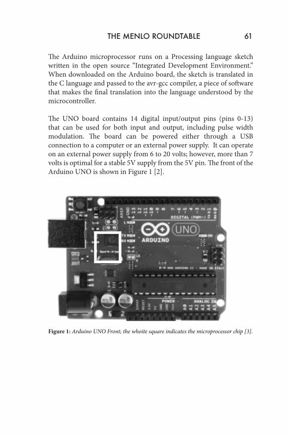
The ‘brain’ of this project is the Arduino UNO microprocessor board. The board consists of the following: a small chip, an ATmega328 microprocessor—wired in a small circuit that connects it to a USB port through which sketches can be uploaded, a battery port through which it can receive power, and input/output pins. In this project, the board receives input from the range finders and controls each of the car’s four wheels via pulse width modulation.
THE MENLO ROUNDTABLE 61
The Arduino microprocessor runs on a Processing language sketch written in the open source “Integrated Development Environment.” When downloaded on the Arduino board, the sketch is translated in the C language and passed to the avr-gcc compiler, a piece of software that makes the final translation into the language understood by the microcontroller. The UNO board contains 14 digital input/output pins (pins 0-13) that can be used for both input and output, including pulse width modulation. The board can be powered either through a USB connection to a computer or an external power supply. It can operate on an external power supply from 6 to 20 volts; however, more than 7 volts is optimal for a stable 5V supply from the 5V pin. The front of the Arduino UNO is shown in Figure 1 [2].
Figure 1: Arduino UNO Front; the whoite square indicates the microprocessor chip [3].
62 Claire Chen
4.2 Range Finders
4.2.1 Ultrasonic Range Finder
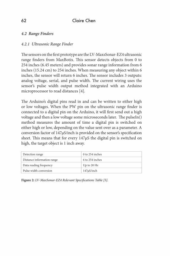
The sensors on the first prototype are the LV-MaxsSonar-EZ4 ultrasonic range finders from MaxBotix. This sensor detects objects from 0 to 254 inches (6.45 meters) and provides sonar range information from 6 inches (15.24 cm) to 254 inches. When measuring any object within 6 inches, the sensor will return 6 inches. The sensor includes 3 outputs: analog voltage, serial, and pulse width. The current wiring uses the sensor’s pulse width output method integrated with an Arduino microprocessor to read distances [4].
The Arduino’s digital pins read in and can be written to either high or low voltages. When the PW pin on the ultrasonic range finder is connected to a digital pin on the Arduino, it will first send out a high voltage and then a low voltage some microseconds later. The pulseIn() method measures the amount of time a digital pin is switched on either high or low, depending on the value sent over as a parameter. A conversion factor of 147µS/inch is provided on the sensor’s specification sheet. This means that for every 147µS the digital pin is switched on high, the target object is 1 inch away.
Detection range 0 to 254 inches
Distance information range 6 to 254 inches
Data reading frequency Up to 20 Hz
Pulse width conversion 147µS/inch
Figure 2: LV-MaxSonar-EZ4 Relevant Specifications Table [5].
THE MENLO ROUNDTABLE 63
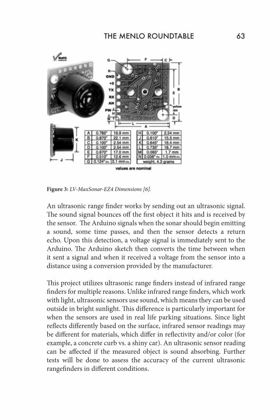
Figure 3: LV-MaxSonar-EZ4 Dimensions [6].
An ultrasonic range finder works by sending out an ultrasonic signal. The sound signal bounces off the first object it hits and is received by the sensor. The Arduino signals when the sonar should begin emitting a sound, some time passes, and then the sensor detects a return echo. Upon this detection, a voltage signal is immediately sent to the Arduino. The Arduino sketch then converts the time between when it sent a signal and when it received a voltage from the sensor into a distance using a conversion provided by the manufacturer.
This project utilizes ultrasonic range finders instead of infrared range finders for multiple reasons. Unlike infrared range finders, which work with light, ultrasonic sensors use sound, which means they can be used outside in bright sunlight. This difference is particularly important for when the sensors are used in real life parking situations. Since light reflects differently based on the surface, infrared sensor readings may be different for materials, which differ in reflectivity and/or color (for example, a concrete curb vs. a shiny car). An ultrasonic sensor reading can be affected if the measured object is sound absorbing. Further tests will be done to assess the accuracy of the current ultrasonic rangefinders in different conditions.
64 Claire Chen
The code used to read distances with an Arduino using pulse width was adapted from code written by Bruce Allen in 2009. Shown below is the code used to integrate two MaxSonar range finders with the Arduino including short explanations for each line. The wiring for one sensor connected to digital pin 7 on the Arduino is shown in Figure 4. The wiring is the same for all additional sensors.
One sensor sketch:
//Digital pin 7 is for reading in the pulse width from the MaxSonar device.//These variables are constant because the pins will not change throughout execution of this code.const int pwPin1 = 7;//Variables needed to store valueslong pulse1, inches1, cm1;void setup() { //Opens a serial connection to send results back to PC console Serial.begin(9600);}
void loop() { pinMode(pwPin1, INPUT); //Used to read in the pulse that is being sent by the MaxSonar device. //Pulse Width representation with a scale factor of 147 uS per Inch. pulse1 = pulseIn(pwPin1, HIGH); //147uS per inch inches1 = pulse1/147; //change inches to centimetres cm1 = inches1 * 2.54; Serial.print(“PW 1: “); Serial.print(inches1); Serial.print(“in, “);
THE MENLO ROUNDTABLE 65
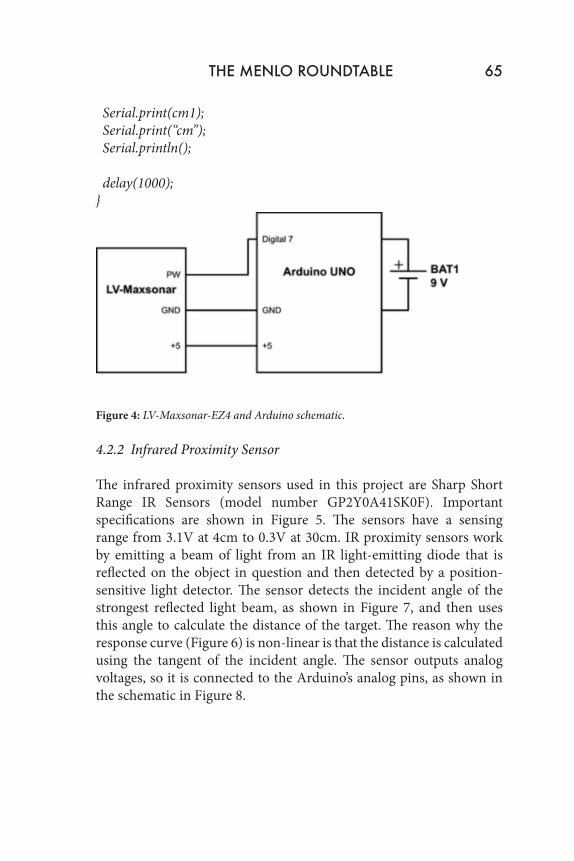
Serial.print(cm1); Serial.print(“cm”); Serial.println(); delay(1000);}
Figure 4: LV-Maxsonar-EZ4 and Arduino schematic.
4.2.2 Infrared Proximity Sensor
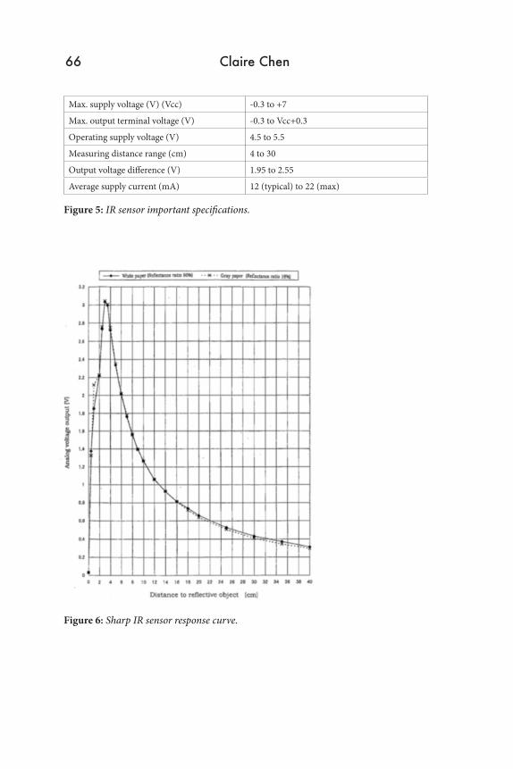
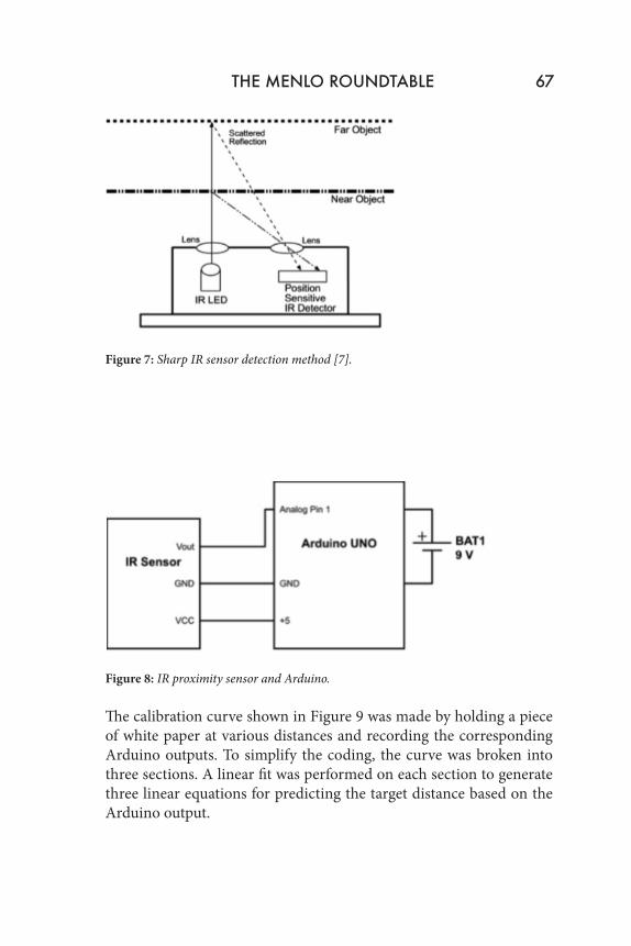
The infrared proximity sensors used in this project are Sharp Short Range IR Sensors (model number GP2Y0A41SK0F). Important specifications are shown in Figure 5. The sensors have a sensing range from 3.1V at 4cm to 0.3V at 30cm. IR proximity sensors work by emitting a beam of light from an IR light-emitting diode that is reflected on the object in question and then detected by a position-sensitive light detector. The sensor detects the incident angle of the strongest reflected light beam, as shown in Figure 7, and then uses this angle to calculate the distance of the target. The reason why the response curve (Figure 6) is non-linear is that the distance is calculated using the tangent of the incident angle. The sensor outputs analog voltages, so it is connected to the Arduino’s analog pins, as shown in the schematic in Figure 8.
66 Claire Chen
Max. supply voltage (V) (Vcc) -0.3 to +7
Max. output terminal voltage (V) -0.3 to Vcc+0.3
Operating supply voltage (V) 4.5 to 5.5
Measuring distance range (cm) 4 to 30
Output voltage difference (V) 1.95 to 2.55
Average supply current (mA) 12 (typical) to 22 (max)
Figure 5: IR sensor important specifications.
Figure 6: Sharp IR sensor response curve.
THE MENLO ROUNDTABLE 67
Figure 7: Sharp IR sensor detection method [7].
Figure 8: IR proximity sensor and Arduino.
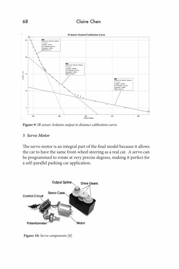
The calibration curve shown in Figure 9 was made by holding a piece of white paper at various distances and recording the corresponding Arduino outputs. To simplify the coding, the curve was broken into three sections. A linear fit was performed on each section to generate three linear equations for predicting the target distance based on the Arduino output.
68 Claire Chen
Figure 9: IR sensor Arduino output to distance calibration curve.
5 Servo Motor
The servo motor is an integral part of the final model because it allows the car to have the same front-wheel steering as a real car. A servo can be programmed to rotate at very precise degrees, making it perfect for a self-parallel parking car application.
Figure 10: Servo components [8].
THE MENLO ROUNDTABLE 69
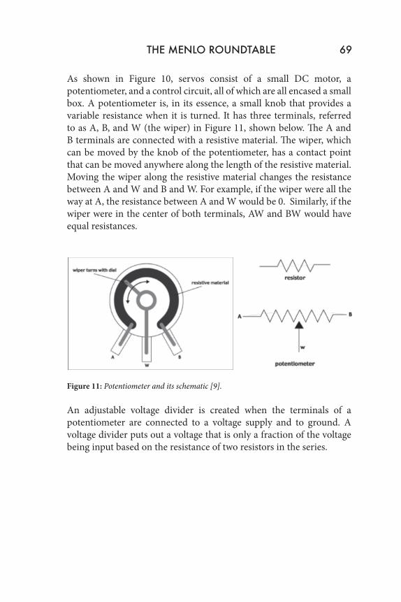
As shown in Figure 10, servos consist of a small DC motor, a potentiometer, and a control circuit, all of which are all encased a small box. A potentiometer is, in its essence, a small knob that provides a variable resistance when it is turned. It has three terminals, referred to as A, B, and W (the wiper) in Figure 11, shown below. The A and B terminals are connected with a resistive material. The wiper, which can be moved by the knob of the potentiometer, has a contact point that can be moved anywhere along the length of the resistive material. Moving the wiper along the resistive material changes the resistance between A and W and B and W. For example, if the wiper were all the way at A, the resistance between A and W would be 0. Similarly, if the wiper were in the center of both terminals, AW and BW would have equal resistances.
Figure 11: Potentiometer and its schematic [9].
An adjustable voltage divider is created when the terminals of a potentiometer are connected to a voltage supply and to ground. A voltage divider puts out a voltage that is only a fraction of the voltage being input based on the resistance of two resistors in the series.
70 Claire Chen
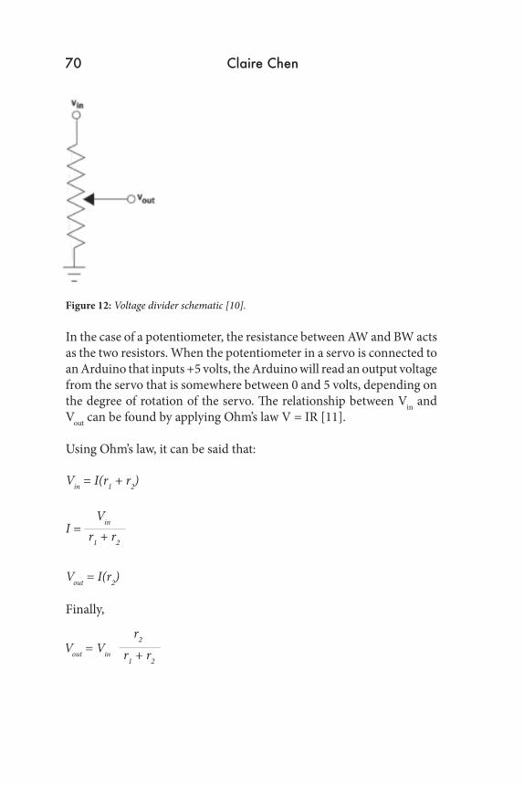
Figure 12: Voltage divider schematic [10].
In the case of a potentiometer, the resistance between AW and BW acts as the two resistors. When the potentiometer in a servo is connected to an Arduino that inputs +5 volts, the Arduino will read an output voltage from the servo that is somewhere between 0 and 5 volts, depending on the degree of rotation of the servo. The relationship between Vin and Vout can be found by applying Ohm’s law V = IR [11].
Using Ohm’s law, it can be said that:
Finally,
Vin = I(r1 + r2)
I =
Vout = I(r2)
Vin
r1 + r2
Vout = Vin r1 + r2
r2
THE MENLO ROUNDTABLE 71
The potentiometer is connected to an electric motor, and when the electric motor spins, it changes the resistance of the potentiometer. If a servo is programmed to rotate a certain number of degrees, the motor will rotate until the potentiometer reaches the corresponding resistance value. A servo is controlled through pulse width modulation, meaning that electrical pulses of varying widths are sent through the control wire. A typical servo, such as the servo utilized in this project, can only rotate 90˚ to either side from a neutral position, thus allowing 180˚ of motion in total. For most servos, a 1.5ms pulse will make it turn to a neutral position, 0˚ with a 1ms pulse, and 180˚ with a 2ms pulse [12].
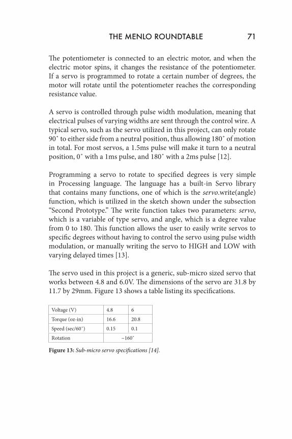
Programming a servo to rotate to specified degrees is very simple in Processing language. The language has a built-in Servo library that contains many functions, one of which is the servo.write(angle) function, which is utilized in the sketch shown under the subsection “Second Prototype.” The write function takes two parameters: servo, which is a variable of type servo, and angle, which is a degree value from 0 to 180. This function allows the user to easily write servos to specific degrees without having to control the servo using pulse width modulation, or manually writing the servo to HIGH and LOW with varying delayed times [13]. The servo used in this project is a generic, sub-micro sized servo that works between 4.8 and 6.0V. The dimensions of the servo are 31.8 by 11.7 by 29mm. Figure 13 shows a table listing its specifications.
Voltage (V) 4.8 6
Torque (oz-in) 16.6 20.8
Speed (sec/60˚) 0.15 0.1
Rotation ~160˚
Figure 13: Sub-micro servo specifications [14].
72 Claire Chen
5.1 H-Bridge Integrated Circuit
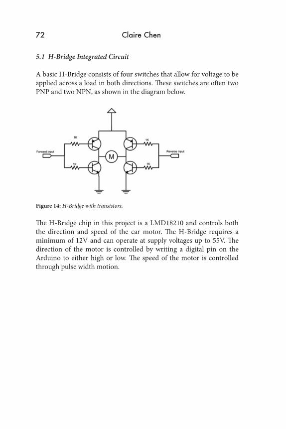
A basic H-Bridge consists of four switches that allow for voltage to be applied across a load in both directions. These switches are often two PNP and two NPN, as shown in the diagram below.
Figure 14: H-Bridge with transistors.
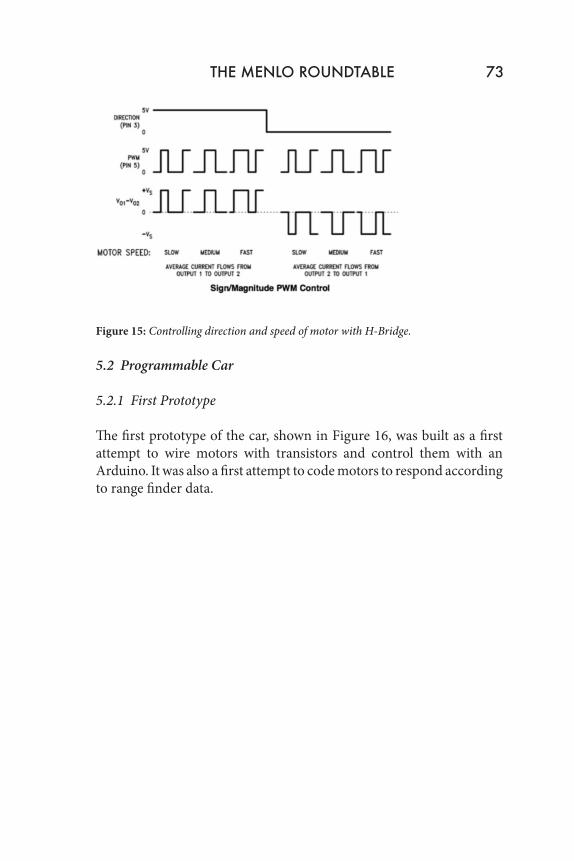
The H-Bridge chip in this project is a LMD18210 and controls both the direction and speed of the car motor. The H-Bridge requires a minimum of 12V and can operate at supply voltages up to 55V. The direction of the motor is controlled by writing a digital pin on the Arduino to either high or low. The speed of the motor is controlled through pulse width motion.
THE MENLO ROUNDTABLE 73
Figure 15: Controlling direction and speed of motor with H-Bridge.
5.2 Programmable Car
5.2.1 First Prototype
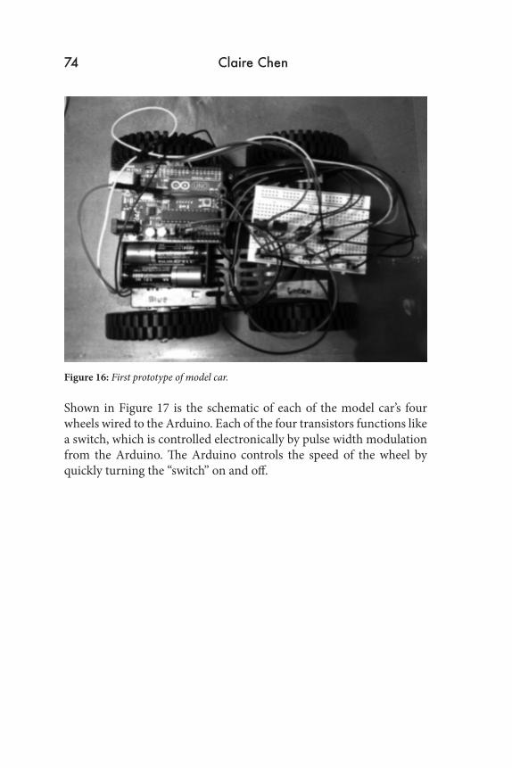
The first prototype of the car, shown in Figure 16, was built as a first attempt to wire motors with transistors and control them with an Arduino. It was also a first attempt to code motors to respond according to range finder data.
74 Claire Chen
Figure 16: First prototype of model car.
Shown in Figure 17 is the schematic of each of the model car’s four wheels wired to the Arduino. Each of the four transistors functions like a switch, which is controlled electronically by pulse width modulation from the Arduino. The Arduino controls the speed of the wheel by quickly turning the “switch” on and off.
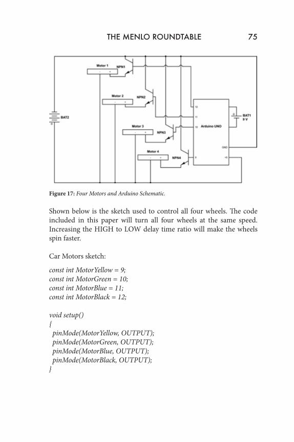
Figure 17: Four Motors and Arduino Schematic.
Shown below is the sketch used to control all four wheels. The code included in this paper will turn all four wheels at the same speed. Increasing the HIGH to LOW delay time ratio will make the wheels spin faster.
Car Motors sketch:
const int MotorYellow = 9;const int MotorGreen = 10;const int MotorBlue = 11;const int MotorBlack = 12;
void setup(){ pinMode(MotorYellow, OUTPUT); pinMode(MotorGreen, OUTPUT); pinMode(MotorBlue, OUTPUT); pinMode(MotorBlack, OUTPUT);}
THE MENLO ROUNDTABLE 75
void loop(){digitalWrite(MotorYellow, HIGH); delay(10); digitalWrite(MotorYellow, LOW); delay(10); digitalWrite(MotorGreen, HIGH); delay(10); digitalWrite(MotorGreen, LOW); delay(10); digitalWrite(MotorBlue, HIGH); delay(10); digitalWrite(MotorBlue, LOW); delay(10); digitalWrite(MotorBlack, HIGH); delay(10); digitalWrite(MotorBlack, LOW); delay(10);}
5.2.2 Second Prototype
The precise turns that a car needs to make to parallel park successfully depends largely on its own dimensions. Since my parking algorithm will ideally work in tandem with a 2008 Toyota Highlander, the final model car will be a scale model of a life-sized Highlander. The algorithm will be tailored to a Highlander, but this does not mean that it will not work on cars with other dimensions; this only means that it will be most precise for a Highlander.
To quicken the construction process of the model, the chassis and the front and rear axles of the car were repurposed from an inexpensive store-bought radio-controlled car. The original purchased car had an axle that allowed the wheels to turn; however, the mechanism with
76 Claire Chen
which they were controlled was a basic motor that rotated to shift a gear and spring system from side to side. This mechanism only allowed the wheels to turn to the most extreme left and right positions, whereas a car that can parallel park would need to have wheels that could rotate to various precise degrees. To solve this problem, the basic motor was replaced with a servo motor which is controlled by the Arduino (see Figure 19).
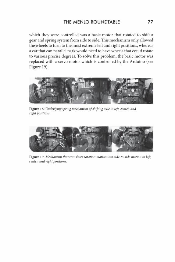
Figure 18: Underlying spring mechanism of shifting axle in left, center, and right positions.
Figure 19: Mechanism that translates rotation motion into side-to-side motion in left, center, and right positions.
THE MENLO ROUNDTABLE 77
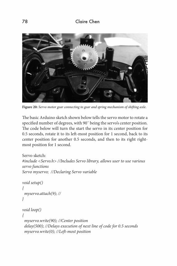
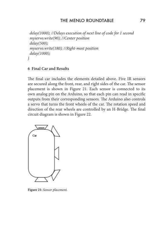
Figure 20: Servo motor gear connecting to gear and spring mechanism of shifting axle.
The basic Arduino sketch shown below tells the servo motor to rotate a specified number of degrees, with 90˚ being the servo’s center position. The code below will turn the start the servo in its center position for 0.5 seconds, rotate it to its left-most position for 1 second, back to its center position for another 0.5 seconds, and then to its right right-most position for 1 second.
Servo sketch:#include <Servo.h> //Includes Servo library, allows user to use various servo functionsServo myservo; //Declaring Servo variable
void setup() { myservo.attach(9); //}
void loop() { myservo.write(90); //Center position delay(500); //Delays execution of next line of code for 0.5 seconds myservo.write(0); //Left-most position
78 Claire Chen
THE MENLO ROUNDTABLE 79
delay(1000); //Delays execution of next line of code for 1 second myservo.write(90); //Center position delay(500); myservo.write(180); //Right-most position delay(1000);}
6 Final Car and Results The final car includes the elements detailed above. Five IR sensors are secured along the front, rear, and right sides of the car. The sensor placement is shown in Figure 21. Each sensor is connected to its own analog pin on the Arduino, so that each pin can read in specific outputs from their corresponding sensors. The Arduino also controls a servo that turns the front wheels of the car. The rotation speed and direction of the rear wheels are controlled by an H-Bridge. The final circuit diagram is shown in Figure 22.
Figure 21: Sensor placement.
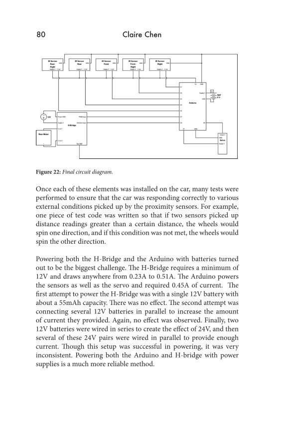
Figure 22: Final circuit diagram.
Once each of these elements was installed on the car, many tests were performed to ensure that the car was responding correctly to various external conditions picked up by the proximity sensors. For example, one piece of test code was written so that if two sensors picked up distance readings greater than a certain distance, the wheels would spin one direction, and if this condition was not met, the wheels would spin the other direction.
Powering both the H-Bridge and the Arduino with batteries turned out to be the biggest challenge. The H-Bridge requires a minimum of 12V and draws anywhere from 0.23A to 0.51A. The Arduino powers the sensors as well as the servo and required 0.45A of current. The first attempt to power the H-Bridge was with a single 12V battery with about a 55mAh capacity. There was no effect. The second attempt was connecting several 12V batteries in parallel to increase the amount of current they provided. Again, no effect was observed. Finally, two 12V batteries were wired in series to create the effect of 24V, and then several of these 24V pairs were wired in parallel to provide enough current. Though this setup was successful in powering, it was very inconsistent. Powering both the Arduino and H-bridge with power supplies is a much more reliable method.
80 Claire Chen
6.1 Parallel Parking Code
Finally, once the car was responding appropriately to various external conditions, the parallel parking sketch was written and then uploaded onto the Arduino. The algorithm is as follows.
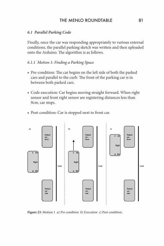
6.1.1 Motion 1: Finding a Parking Space
• Pre-condition: The car begins on the left side of both the parked cars and parallel to the curb. The front of the parking car is in between both parked cars.
• Code execution: Car begins moving straight forward. When right sensor and front right sensor are registering distances less than 9cm, car stops.
• Post-condition: Car is stopped next to front car.
Figure 23: Motion 1 a) Pre-condition b) Execution c) Post-condition.
THE MENLO ROUNDTABLE 81
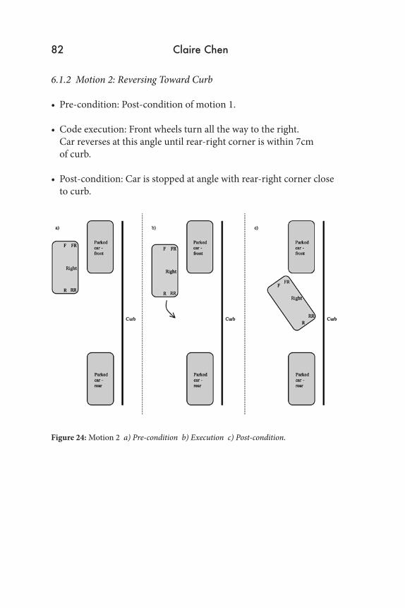
6.1.2 Motion 2: Reversing Toward Curb
• Pre-condition: Post-condition of motion 1.
• Code execution: Front wheels turn all the way to the right. Car reverses at this angle until rear-right corner is within 7cm of curb. • Post-condition: Car is stopped at angle with rear-right corner close to curb.
Figure 24: Motion 2 a) Pre-condition b) Execution c) Post-condition.
82 Claire Chen
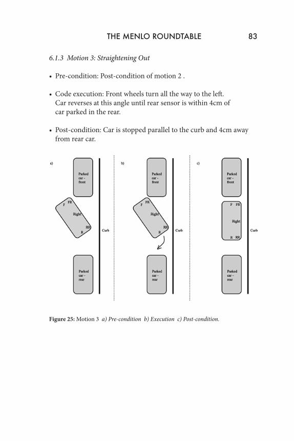
6.1.3 Motion 3: Straightening Out
• Pre-condition: Post-condition of motion 2 .
• Code execution: Front wheels turn all the way to the left. Car reverses at this angle until rear sensor is within 4cm of car parked in the rear.
• Post-condition: Car is stopped parallel to the curb and 4cm away from rear car.
Figure 25: Motion 3 a) Pre-condition b) Execution c) Post-condition.
THE MENLO ROUNDTABLE 83
7 Conclusion
In the end, the basic goal of this project was accomplished. The car is able to steer by itself based on external conditions. It is able to pull into a parking space and reverse until it is positioned in between two parked cars. While the project was generally successful, there are many things that could still be done to improve the quality and performance of the parking system. The first would be to refine the parking algorithm, so that the car is able to fine-tune its position within the parking space. This would likely require additional sensors. The second would be to find a reliable source of power that does not come from power supplies connected to power outlets. Notes
1. “Intelligent Parking Assist System.” Wikipedia. http://en.wikipedia.org/wiki/Intelligent_Parking_Assist_System.
2. Arduino. N.p., n.d. Web. 9 Feb. 2014. <http://arduino.cc/>.
3. Ibid.
4. “MB1040 LV-MaxSonar®-EZ4™.” MaxBotix. N.p., n.d. Web. 9 Feb. 2014. <http://www.maxbotix.com/Ultrasonic_Sensors/MB1040.htm>.
5. Ibid.
6. Ibid.
7. Mbed. N.p., n.d. Web. 14 May 2014. <https://mbed.org/>.
8. “How Servo Motors Work.” Jameco Electronics. N.p., n.d. Web. 10 Mar. 2014. <http://www.jameco.com/Jameco/workshop/howitworks/ how-servo-motors-work.html>.
84 Claire Chen
9. Feddersen, Jeff. “Inside the Potentiometer.” Fddrsn. N.p., n.d. Web. 10 Mar. 2014. <http://fddrsn.net/pcomp/examples/potentiometers.html>.
10. Ibid.
11. Ibid.
12. “How Servo Motors Work.” Jameco Electronics. N.p., n.d. Web. 10 Mar. 2014. <http://www.jameco.com/Jameco/workshop/howitworks/how-servo-motors-work.html>.
13. Arduino. N.p., n.d. Web. 10 March. 2014. <http://arduino.cc/>.
14. Servo - Generic (Sub-Micro Size).” SparkFun. N.p., n.d. Web. 10 Mar. 2014. <https://www.sparkfun.com/products/9065>.
Appendix
int FRONT = 3;double front_val = 0;double front_distance = 0;
int FRONT_RIGHT = 2;double front_right_val = 0;double front_right_distance = 0;
int REAR = 4;double rear_val = 0;double rear_distance = 0;
int REAR_RIGHT = 5;double rear_right_val = 0;double rear_right_distance = 0;
THE MENLO ROUNDTABLE 85
int RIGHT = 1;double right_val = 0;double right_distance = 0;
const int PulseWidth = 7;const int Direction = 8; //LOW is backward, HIGH is forward
#include <Servo.h>Servo servo;
void setup(){ Serial.begin(9600);
servo.attach(9);
pinMode(PulseWidth, OUTPUT); pinMode(Direction, OUTPUT);
digitalWrite(PulseWidth, HIGH);
//sets intial front right distance and right distance front_right_distance = frontRightDistance(); right_distance = rightDistance();
//find parking space,assuming front of car is between two parked cars //stop when ready to begin reversing while(!(front_right_distance < 9 && right_distance < 9 )) { front_right_distance = frontRightDistance(); right_distance = rightDistance();
servo.write(90); forwardDrive(); }
//when ready to begin reversing, turn wheels to right
86 Claire Chen
servo.write(180);
//reverse to the right //stop when rear right corner is close to curb rear_right_distance = rearRightDistance();
while(!(rear_right_distance < 7)) { rear_right_distance = rearRightDistance(); reverseTurn(); }
//turn wheels left servo.write(0);
//reverse straight backwards //stop before rear hits rear car rear_distance = rearDistance(); while(!(rear_distance < 4)) { rear_distance = rearDistance(); reverseTurn(); } //turn wheels back to center servo.write(90);
}
void loop(){ }
double frontDistance(){ front_val = analogRead(FRONT);
THE MENLO ROUNDTABLE 87
if(front_val >= 87 && front_val <= 139) { front_distance = -0.1724 * front_val + 40.52; } else if(front_val > 139 && front_val <= 260) { front_distance = -0.06306 * front_val + 25.16; } else { front_distance = -0.01615 * front_val + 12.42; } Serial.print(“FRONT: “); Serial.println(front_distance);
return front_distance;}
double frontRightDistance(){ front_right_val = analogRead(FRONT_RIGHT);
if(front_right_val >= 87 && front_right_val <= 139) { front_right_distance = -0.1724 * front_right_val + 40.52; } else if(front_right_val > 139 && front_right_val <= 260) { front_right_distance = -0.06306 * front_right_val + 25.16; } else { front_right_distance = -0.01615 * front_right_val + 12.42; } Serial.print(“FRONT RIGHT: “); Serial.println(front_right_distance);
88 Claire Chen
return front_right_distance;}
double rearDistance(){ rear_val = analogRead(REAR);
if(rear_val >= 87 && rear_val <= 139) { rear_distance = -0.1724 * rear_val + 40.52; } else if(rear_val > 139 && rear_val <= 260) { rear_distance = -0.06306 * rear_val + 25.16; } else { rear_distance = -0.01615 * rear_val + 12.42; } Serial.print(“REAR: “); Serial.println(rear_distance);
return rear_distance;}
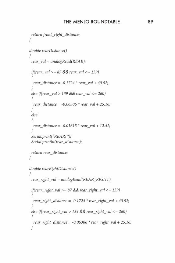
double rearRightDistance(){ rear_right_val = analogRead(REAR_RIGHT);
if(rear_right_val >= 87 && rear_right_val <= 139) { rear_right_distance = -0.1724 * rear_right_val + 40.52; } else if(rear_right_val > 139 && rear_right_val <= 260) { rear_right_distance = -0.06306 * rear_right_val + 25.16; }
THE MENLO ROUNDTABLE 89
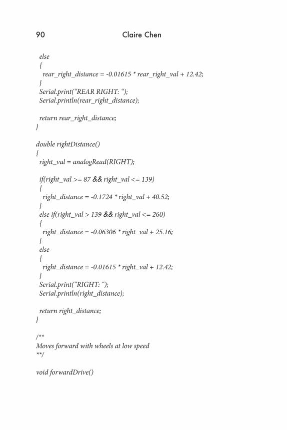
else { rear_right_distance = -0.01615 * rear_right_val + 12.42; } Serial.print(“REAR RIGHT: “); Serial.println(rear_right_distance);
return rear_right_distance;}
double rightDistance(){ right_val = analogRead(RIGHT);
if(right_val >= 87 && right_val <= 139) { right_distance = -0.1724 * right_val + 40.52; } else if(right_val > 139 && right_val <= 260) { right_distance = -0.06306 * right_val + 25.16; } else { right_distance = -0.01615 * right_val + 12.42; } Serial.print(“RIGHT: “); Serial.println(right_distance);
return right_distance;}
/**Moves forward with wheels at low speed**/
void forwardDrive()
90 Claire Chen
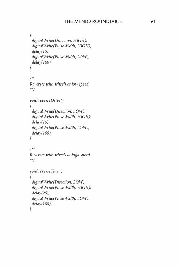
{ digitalWrite(Direction, HIGH); digitalWrite(PulseWidth, HIGH); delay(15); digitalWrite(PulseWidth, LOW); delay(100);}
/**Reverses with wheels at low speed**/
void reverseDrive(){ digitalWrite(Direction, LOW); digitalWrite(PulseWidth, HIGH); delay(15); digitalWrite(PulseWidth, LOW); delay(100);}
/**Reverses with wheels at high speed**/
void reverseTurn(){ digitalWrite(Direction, LOW); digitalWrite(PulseWidth, HIGH); delay(25); digitalWrite(PulseWidth, LOW); delay(100);}
THE MENLO ROUNDTABLE 91


![Untitled-1 [] · 740,000 Right To Use Additional Car Parking Charges: o Premium Covered Car Parking = INR 400,000 o Open Car Parking = INR 300,000 o Combined Car Parking = INR 200,000](https://static.fdocuments.us/doc/165x107/5ec23107d922333dc921e4cc/untitled-1-740000-right-to-use-additional-car-parking-charges-o-premium-covered.jpg)