
Autonomous Indoor Hovering with a Quadrotor - home...
10
Autonomous Indoor Hovering with a Quadrotor G. Angeletti, J. R. Pereira Valente, L. Iocchi, D. Nardi Sapienza University of Rome, Dept. of Computer and System Science, Via Ariosto 25, 00185 Rome, Italy http://www.dis.uniroma1.it Abstract. Mini and micro UAVs are very promising platforms for se- curity and surveillance applications, because of their increased mobility in the environment. Moreover, they can effectively employed also in in- door environments. On the other hand, the limited payload for carrying sensors and the limited computational power on-board make the devel- opment of autonomous UAVs very challenging. In this paper we present hardware and software development of a quadrobot that can reliably navigate in indoor environments. In particular, we focus on the problem of indoor hovering by controlling the 6 DOF of the vehicle with different on-board and off-board sensors. Key words: quadrotor, UAV, indoor, hovering 1 Introduction Recently, the quadrotor has become a standard platform in the experiments and applications of mini unmanned aerial vehicles (mini-UAVs). The great manoeu- vrability and small size of this platform make it suitable for indoor use, where the development of other kinds of UAVs is still limited. In this scenario, a quadrotor could be used in security and surveillance tasks, where the capacity of flying above ground obstacles give it a great advantage over ground robots. Indoor un- supervised flight of aerial vehicles is a hard challenge, because it is not possible to use global positioninng systems (such as GPS) as in outdoor applications. Moreover, quadrotors have usually limited payload that implies a selection of sensors that can be placed onboard. Finally, the dynamics of a flying vehicle is more complex than that of a ground robot, so that even the hovering becomes a difficult task. In this paper, we propose a vision based and a laser based approach for the quadrotor indoor hovering. Our purpose is to propose two strategies that use different sensors in order to experiment the benefits and disadvantages of both the approaches. 2 Related Work Among the several kinds of mini-UAVs, quadrotors are probably the most com- mon. This platform has a “plus” shape with one rotor per corner and has been Workshop Proceedings of SIMPAR 2008 Intl. Conf. on SIMULATION, MODELING and PROGRAMMING for AUTONOMOUS ROBOTS Venice(Italy) 2008 November,3-4 ISBN 978-88-95872-01-8 pp. 472-481
Transcript of Autonomous Indoor Hovering with a Quadrotor - home...

Autonomous Indoor Hovering with a Quadrotor
G. Angeletti, J. R. Pereira Valente, L. Iocchi, D. Nardi
Sapienza University of Rome,Dept. of Computer and System Science,
Via Ariosto 25, 00185 Rome, Italyhttp://www.dis.uniroma1.it
Abstract. Mini and micro UAVs are very promising platforms for se-curity and surveillance applications, because of their increased mobilityin the environment. Moreover, they can effectively employed also in in-door environments. On the other hand, the limited payload for carryingsensors and the limited computational power on-board make the devel-opment of autonomous UAVs very challenging. In this paper we presenthardware and software development of a quadrobot that can reliablynavigate in indoor environments. In particular, we focus on the problemof indoor hovering by controlling the 6 DOF of the vehicle with differenton-board and off-board sensors.
Key words: quadrotor, UAV, indoor, hovering
1 Introduction
Recently, the quadrotor has become a standard platform in the experiments andapplications of mini unmanned aerial vehicles (mini-UAVs). The great manoeu-vrability and small size of this platform make it suitable for indoor use, where thedevelopment of other kinds of UAVs is still limited. In this scenario, a quadrotorcould be used in security and surveillance tasks, where the capacity of flyingabove ground obstacles give it a great advantage over ground robots. Indoor un-supervised flight of aerial vehicles is a hard challenge, because it is not possibleto use global positioninng systems (such as GPS) as in outdoor applications.Moreover, quadrotors have usually limited payload that implies a selection ofsensors that can be placed onboard. Finally, the dynamics of a flying vehicle ismore complex than that of a ground robot, so that even the hovering becomesa difficult task.
In this paper, we propose a vision based and a laser based approach for thequadrotor indoor hovering. Our purpose is to propose two strategies that usedifferent sensors in order to experiment the benefits and disadvantages of boththe approaches.
2 Related Work
Among the several kinds of mini-UAVs, quadrotors are probably the most com-mon. This platform has a “plus” shape with one rotor per corner and has been
Workshop Proceedings of SIMPAR 2008Intl. Conf. on SIMULATION, MODELING and PROGRAMMING for AUTONOMOUS ROBOTS
Venice(Italy) 2008 November,3-4ISBN 978-88-95872-01-8
pp. 472-481

2 Autonomous indoor hovering with a quadrotor
widely developed by many Universities and research centers. “X3D-BL” [1], “X4-flyer” [2] and “OS4” [3] are examples of quadrotors which are entirely designedand created by a University. In these works, a customized modeling and designapproach was employed, in order to create an effective platform.
Parallel to the hardware development, several efforts have been made in orderto develop autmotic control systems, by considering both on-board and off-boardsensors. Among others, several vision-based approaches for autonomous flight ofUAVs have been studied. In these works the vision system is used to estimatethe quadrotor position and orientation, in order to let it fly autonomously. Usu-ally, a camera is placed on the quadrotor and the image processing is done ona ground station [4, 5] or directly on-board by a dedicated device [6]. The mainissue in this approach concerns the (usually) bad quality images, resulting fromthe camera instability and signal interferences (when the image processing isdone by a ground station). Altug and collaborators [7] used a two cameras ar-chitecture, with one camera placed onboard and the other one on the ground; amarker system allows the application to control the helicopter. However, a visionsystem presents some intrinsic problems, such as the high sensitivity to environ-ment lighting conditions. Therefore, in some works an approach purely basedon distance sensors was used. Roberts and collaborators [8] present a quadrotorthat is autonomously able to take off, fly at a constant altitude and land, usingonly an ultrasonic sensor and four infrared sensors.
In this paper we analyze different combinations of sensors and software forcontrolling a quadrotor in order to maintain a stationary pose (hovering). Wepresent both a vision-based approach, using an external camera placed on theground and a a laser-based control using an on-board laser range finder.
3 System Architecture
3.1 Hardware
The hardware architecture is made of three distinct computational elements:the quadrotor, with its integrated control; the Gumstix boards, which providean ARM processor, a set of input-output ports and a wi-fi connection; a groundstation, used to execute the most complex computations (e.g.: run the visionalgorithm). Furthermore, three different kinds of sensors were used to let thequadrotor sense the environment.
The Quadrotor The aerial platform we have used in our experiments is aquadrotor (Fig. 1) developed by Ascending Technologies [1]. The main featuresof this platform consist of a great robustness – due to the quality materialsused – and an on-board 1 KHz controller, which provides a good flight stability.Moreover, the opportunity to fly the quadrotor and receive its status via a serialport available on-board, makes this platform an excellent base to start developingany autonomous behavior.
Workshop Proceedings of SIMPAR 2008Intl. Conf. on SIMULATION, MODELING and PROGRAMMING for AUTONOMOUS ROBOTS
Venice(Italy) 2008 November,3-4ISBN 978-88-95872-01-8
pp. 472-481

Autonomous indoor hovering with a quadrotor 3
As we said, the quadrotor offers a very-fast embedded controller, which –using data derived from a triaxial accelerometer – makes the quadrotor able tokeep the roll and pitch angles commanded via the radiocontroller or the serialinterface. As a consequence, if the roll and pitch stick in the radiocontroller is leftcentered (or, in the same way, if a roll and pitch zero angle is commanded throughthe serial port), the quadrotor will try to keep an horizontal orientation1. Sincethe quadrotor has not a compass, the yaw command will be an angular velocityrather than an angle; using the on-board gyroscope, the control system will tryto keep the current yaw (if the yaw command is neutral), being unable to keepdirectly a yaw angle. However, as the datafusion is done with an update rate of1 KHz, in the practice the quadrotor needs only occasional yaw corrections.
Fig. 1: The quadrotor X-3D-BL, developed by Ascending Tecnologies.
The Gumstix Boards In order to interact with the quadrotor electronics,three small size boards were added, named respectively: Gumstix, Robostix andWifistix. All these boards are manufactured by Gumstix Inc., specialized inmini-boards 8 x 2 cm.
The Gumstix board provides a 400 MHz ARM processor, without the float-ing point unit, which can execute C and C++ code. Moreover, an optimizedLinux distribution is installed on this board, so that it is possible to use all thefeatures (e.g. multithreading) of an advanced operating system. This board canbe considered as a motherboard, to which one can link many expansion cards,in order to have a wide range of extra functionalities.
In this work, we have used two expansion boards, the Robostix and theWifistix. The first one provides a microcontroller which can drive serial (UART)ports, PWM ports, analog to digital converters and GPIO (General Purpose
1 Obviously, due to the sensors measurement errors, the quadrotor will not keep theposition.
Workshop Proceedings of SIMPAR 2008Intl. Conf. on SIMULATION, MODELING and PROGRAMMING for AUTONOMOUS ROBOTS
Venice(Italy) 2008 November,3-4ISBN 978-88-95872-01-8
pp. 472-481
4 Autonomous indoor hovering with a quadrotor
Input Output) ports. The connection with the Gumstix is achieved via an I2Cbus. The second expansion board allows, as the name “Wifistix” suggests, theuse of the 802.11b/g protocol.
Since the Gumstix boards need a 5V voltage whereas the quadrotor batteryprovides a 11.1V voltage, a Tracopowerr DC-DC voltage converter was used.
The Ground Station Due to the Gumstix hardware limitations, it is possibleto execute only the simplest computations on-board. For the more demandingcomputations, we have used a ground station, that is a high-performance PCwhich keeps the communication with the quadrotor via the Wi-Fi interface.
Sensors. In order to achieve any autonomous behavior, it is necessary to havea feedback of the environment. In our work we have used three kinds of sensors:a sonar, a monocular camera and a laser. The context in which each sensor wasused will be specified in the ”Implementation” section.
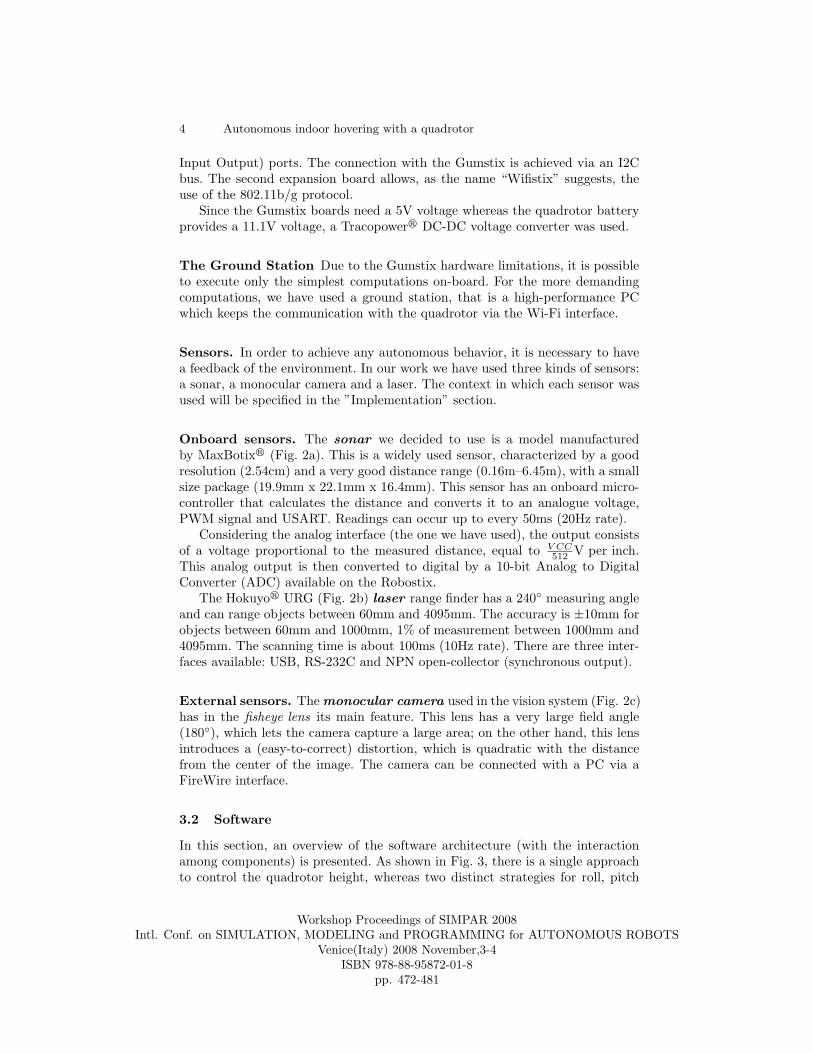
Onboard sensors. The sonar we decided to use is a model manufacturedby MaxBotixr (Fig. 2a). This is a widely used sensor, characterized by a goodresolution (2.54cm) and a very good distance range (0.16m–6.45m), with a smallsize package (19.9mm x 22.1mm x 16.4mm). This sensor has an onboard micro-controller that calculates the distance and converts it to an analogue voltage,PWM signal and USART. Readings can occur up to every 50ms (20Hz rate).
Considering the analog interface (the one we have used), the output consistsof a voltage proportional to the measured distance, equal to V CC
512 V per inch.This analog output is then converted to digital by a 10-bit Analog to DigitalConverter (ADC) available on the Robostix.
The Hokuyor URG (Fig. 2b) laser range finder has a 240◦ measuring angleand can range objects between 60mm and 4095mm. The accuracy is ±10mm forobjects between 60mm and 1000mm, 1% of measurement between 1000mm and4095mm. The scanning time is about 100ms (10Hz rate). There are three inter-faces available: USB, RS-232C and NPN open-collector (synchronous output).
External sensors. The monocular camera used in the vision system (Fig. 2c)has in the fisheye lens its main feature. This lens has a very large field angle(180◦), which lets the camera capture a large area; on the other hand, this lensintroduces a (easy-to-correct) distortion, which is quadratic with the distancefrom the center of the image. The camera can be connected with a PC via aFireWire interface.
3.2 Software
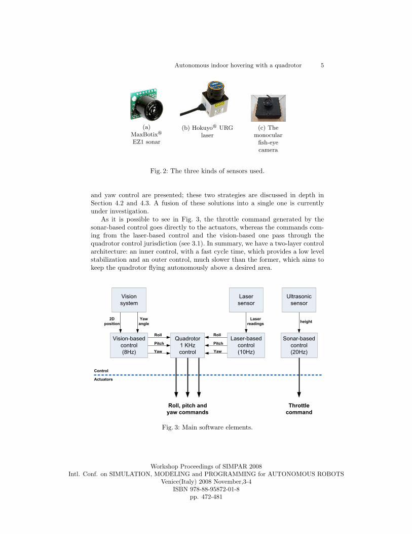
In this section, an overview of the software architecture (with the interactionamong components) is presented. As shown in Fig. 3, there is a single approachto control the quadrotor height, whereas two distinct strategies for roll, pitch
Workshop Proceedings of SIMPAR 2008Intl. Conf. on SIMULATION, MODELING and PROGRAMMING for AUTONOMOUS ROBOTS
Venice(Italy) 2008 November,3-4ISBN 978-88-95872-01-8
pp. 472-481
Autonomous indoor hovering with a quadrotor 5
(a)MaxBotixr
EZ1 sonar
(b) Hokuyor URGlaser
(c) Themonocular
fish-eyecamera
Fig. 2: The three kinds of sensors used.
and yaw control are presented; these two strategies are discussed in depth inSection 4.2 and 4.3. A fusion of these solutions into a single one is currentlyunder investigation.
As it is possible to see in Fig. 3, the throttle command generated by thesonar-based control goes directly to the actuators, whereas the commands com-ing from the laser-based control and the vision-based one pass through thequadrotor control jurisdiction (see 3.1). In summary, we have a two-layer controlarchitecture: an inner control, with a fast cycle time, which provides a low levelstabilization and an outer control, much slower than the former, which aims tokeep the quadrotor flying autonomously above a desired area.
Fig. 3: Main software elements.
Workshop Proceedings of SIMPAR 2008Intl. Conf. on SIMULATION, MODELING and PROGRAMMING for AUTONOMOUS ROBOTS
Venice(Italy) 2008 November,3-4ISBN 978-88-95872-01-8
pp. 472-481
6 Autonomous indoor hovering with a quadrotor
4 Implementation
4.1 Altitude control through sonar
In order to control the quadrotor height, we have used an ultrasonic sensor linkedto the Robostix ADC (see 3.1). This sensor was pointed at the ceiling, whichpresent less obstacles (e.g.: chairs, tables etc.) than the ground. Data comingfrom the sonar are processed by a simple PI (Proportional-Integrative) control(see equation 1), which – proportionately to the gap between the current heightand the desired one – produces a quadrotor throttle command. The integrativeterm – being a purely additive term – was added to compensate the batterydischargement, which makes the throttle command less effective.
u(n)PI =
0-error output︷︸︸︷M0 +
correction at the step n︷ ︸︸ ︷(Kp · (h(n)
des − h(n)mis))︸ ︷︷ ︸
proportional term
+ (Ki ·n∑
i=0
Ei)︸ ︷︷ ︸integrative term
. (1)
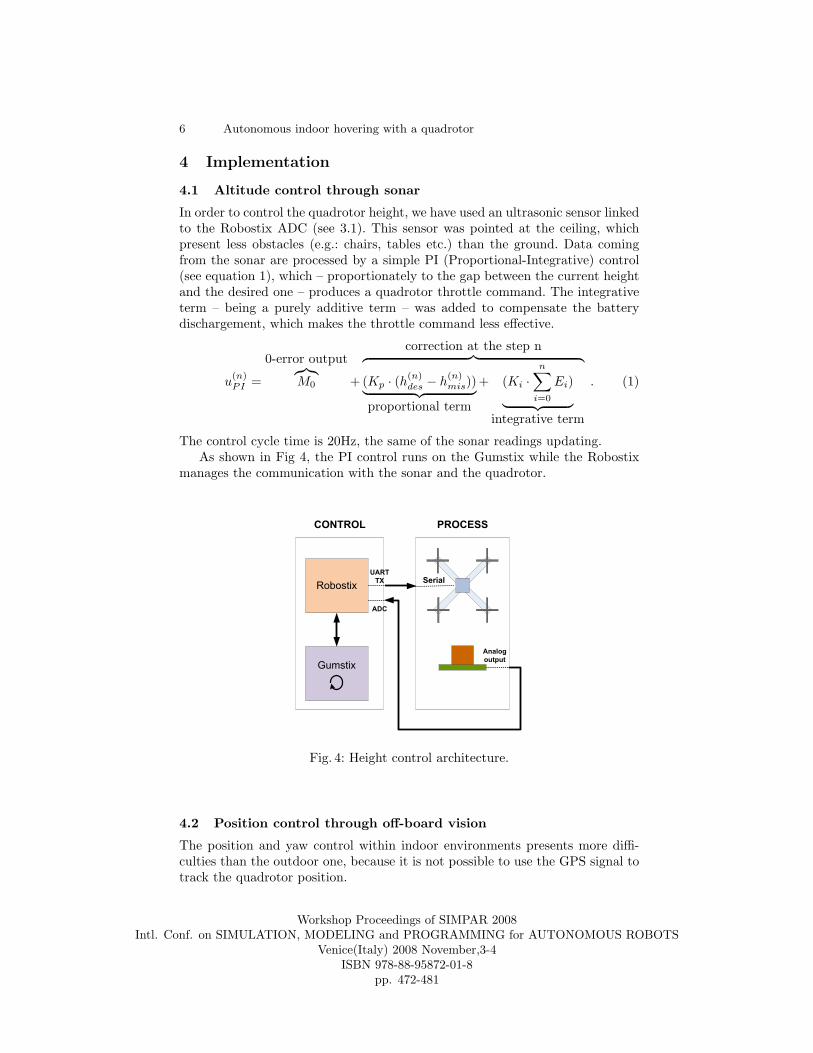
The control cycle time is 20Hz, the same of the sonar readings updating.As shown in Fig 4, the PI control runs on the Gumstix while the Robostix
manages the communication with the sonar and the quadrotor.
Fig. 4: Height control architecture.
4.2 Position control through off-board vision
The position and yaw control within indoor environments presents more diffi-culties than the outdoor one, because it is not possible to use the GPS signal totrack the quadrotor position.
Workshop Proceedings of SIMPAR 2008Intl. Conf. on SIMULATION, MODELING and PROGRAMMING for AUTONOMOUS ROBOTS
Venice(Italy) 2008 November,3-4ISBN 978-88-95872-01-8
pp. 472-481
Autonomous indoor hovering with a quadrotor 7
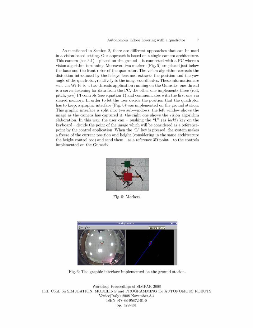
As mentioned in Section 2, there are different approaches that can be usedin a vision-based setting. Our approach is based on a single camera architecture.This camera (see 3.1) – placed on the ground – is connected with a PC where avision algorithm is running. Moreover, two markers (Fig. 5) are placed just belowthe base and the front rotor of the quadrotor. The vision algorithm corrects thedistortion introduced by the fisheye lens and extracts the position and the yawangle of the quadrotor, relatively to the image coordinates. These information aresent via Wi-Fi to a two threads application running on the Gumstix: one threadis a server listening for data from the PC; the other one implements three (roll,pitch, yaw) PI controls (see equation 1) and communicates with the first one viashared memory. In order to let the user decide the position that the quadrotorhas to keep, a graphic interface (Fig. 6) was implemented on the ground station.This graphic interface is split into two sub-windows: the left window shows theimage as the camera has captured it; the right one shows the vision algorithmelaboration. In this way, the user can – pushing the “L” (as lock! ) key on thekeyboard – decide the point of the image which will be considered as a reference-point by the control application. When the “L” key is pressed, the system makesa freeze of the current position and height (considering in the same architecturethe height control too) and send them – as a reference 3D point – to the controlsimplemented on the Gumstix.
Fig. 5: Markers.
Fig. 6: The graphic interface implemented on the ground station.
Workshop Proceedings of SIMPAR 2008Intl. Conf. on SIMULATION, MODELING and PROGRAMMING for AUTONOMOUS ROBOTS
Venice(Italy) 2008 November,3-4ISBN 978-88-95872-01-8
pp. 472-481
8 Autonomous indoor hovering with a quadrotor
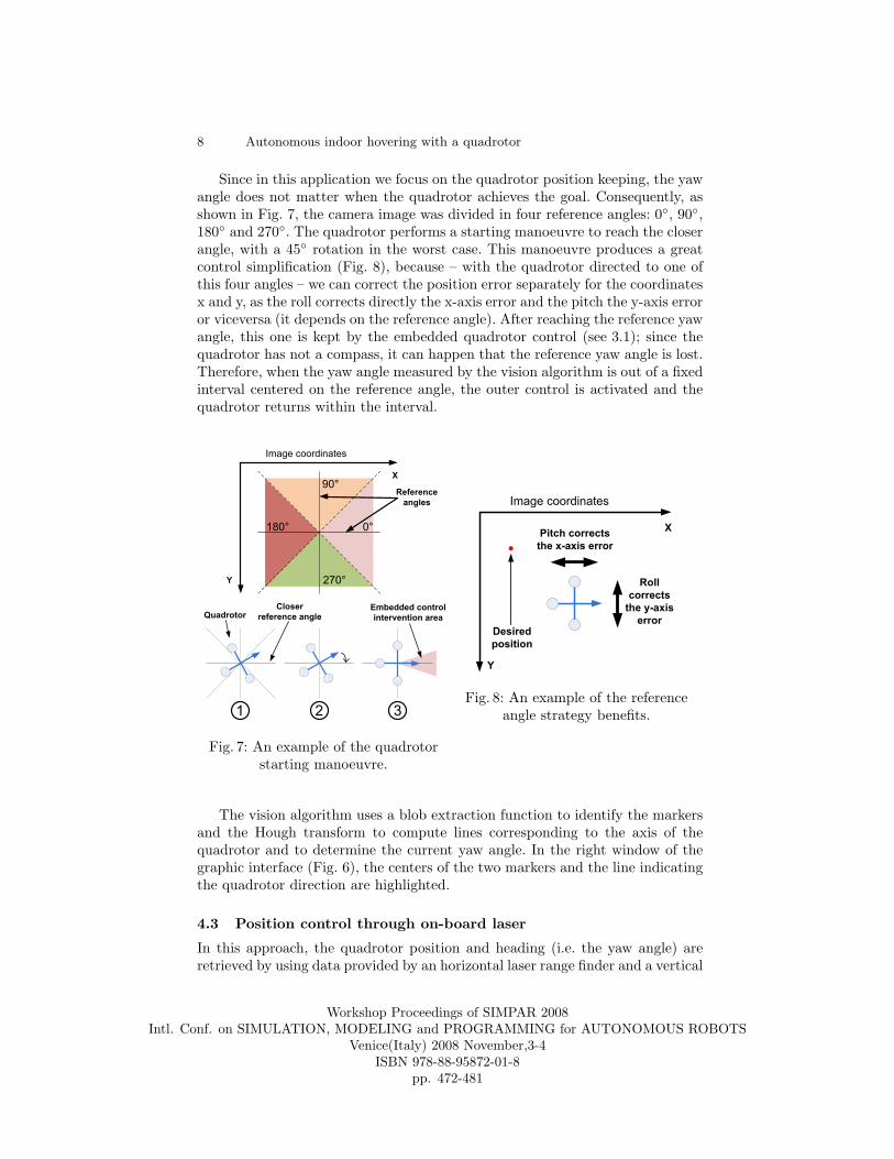
Since in this application we focus on the quadrotor position keeping, the yawangle does not matter when the quadrotor achieves the goal. Consequently, asshown in Fig. 7, the camera image was divided in four reference angles: 0◦, 90◦,180◦ and 270◦. The quadrotor performs a starting manoeuvre to reach the closerangle, with a 45◦ rotation in the worst case. This manoeuvre produces a greatcontrol simplification (Fig. 8), because – with the quadrotor directed to one ofthis four angles – we can correct the position error separately for the coordinatesx and y, as the roll corrects directly the x-axis error and the pitch the y-axis erroror viceversa (it depends on the reference angle). After reaching the reference yawangle, this one is kept by the embedded quadrotor control (see 3.1); since thequadrotor has not a compass, it can happen that the reference yaw angle is lost.Therefore, when the yaw angle measured by the vision algorithm is out of a fixedinterval centered on the reference angle, the outer control is activated and thequadrotor returns within the interval.
Fig. 7: An example of the quadrotorstarting manoeuvre.
Fig. 8: An example of the referenceangle strategy benefits.
The vision algorithm uses a blob extraction function to identify the markersand the Hough transform to compute lines corresponding to the axis of thequadrotor and to determine the current yaw angle. In the right window of thegraphic interface (Fig. 6), the centers of the two markers and the line indicatingthe quadrotor direction are highlighted.
4.3 Position control through on-board laser
In this approach, the quadrotor position and heading (i.e. the yaw angle) areretrieved by using data provided by an horizontal laser range finder and a vertical
Workshop Proceedings of SIMPAR 2008Intl. Conf. on SIMULATION, MODELING and PROGRAMMING for AUTONOMOUS ROBOTS
Venice(Italy) 2008 November,3-4ISBN 978-88-95872-01-8
pp. 472-481
Autonomous indoor hovering with a quadrotor 9
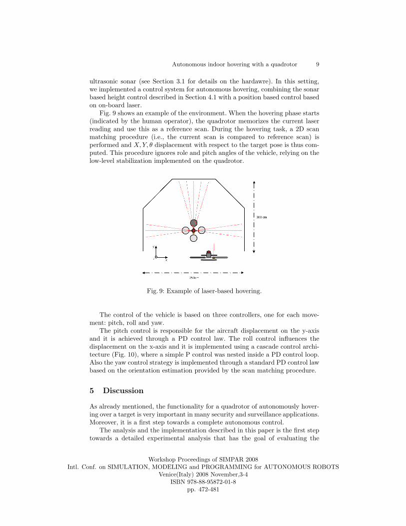
ultrasonic sonar (see Section 3.1 for details on the hardawre). In this setting,we implemented a control system for autonomous hovering, combining the sonarbased height control described in Section 4.1 with a position based control basedon on-board laser.
Fig. 9 shows an example of the environment. When the hovering phase starts(indicated by the human operator), the quadrotor memorizes the current laserreading and use this as a reference scan. During the hovering task, a 2D scanmatching procedure (i.e., the current scan is compared to reference scan) isperformed and X,Y, θ displacement with respect to the target pose is thus com-puted. This procedure ignores role and pitch angles of the vehicle, relying on thelow-level stabilization implemented on the quadrotor.
Fig. 9: Example of laser-based hovering.
The control of the vehicle is based on three controllers, one for each move-ment: pitch, roll and yaw.
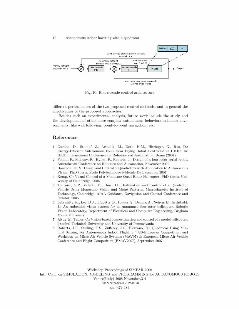
The pitch control is responsible for the aircraft displacement on the y-axisand it is achieved through a PD control law. The roll control influences thedisplacement on the x-axis and it is implemented using a cascade control archi-tecture (Fig. 10), where a simple P control was nested inside a PD control loop.Also the yaw control strategy is implemented through a standard PD control lawbased on the orientation estimation provided by the scan matching procedure.
5 Discussion
As already mentioned, the functionality for a quadrotor of autonomously hover-ing over a target is very important in many security and surveillance applications.Moreover, it is a first step towards a complete autonomous control.
The analysis and the implementation described in this paper is the first steptowards a detailed experimental analysis that has the goal of evaluating the
Workshop Proceedings of SIMPAR 2008Intl. Conf. on SIMULATION, MODELING and PROGRAMMING for AUTONOMOUS ROBOTS
Venice(Italy) 2008 November,3-4ISBN 978-88-95872-01-8
pp. 472-481
10 Autonomous indoor hovering with a quadrotor
Fig. 10: Roll cascade control architecture.
different performances of the two proposed control methods, and in general theeffectiveness of the proposed approaches.
Besides such an experimental analysis, future work include the study andthe development of other more complex autonomous behaviors in indoor envi-ronments, like wall following, point-to-point navigation, etc.
References
1. Gurdan, D., Stumpf, J., Achtelik, M., Doth, K.M., Hirzinger, G., Rus, D.:Energy-Efficient Autonomous Four-Rotor Flying Robot Controlled at 1 KHz. In:IEEE International Conference on Robotics and Automation. Rome (2007)
2. Pound, P., Mahony, R., Hynes, P., Roberts, J.: Design of a four-rotor aerial robot.Australasian Conference on Robotics and Automation, November 2002
3. Bouabdallah, S.: Design and Control of Quadrotors with Application to AutonomousFlying. PhD thesis, Ecole Polytechnique Federale De Lausanne, 2007
4. Kemp, C.: Visual Control of a Miniature Quad-Rotor Helicopter. PhD thesis, Uni-versity of Cambridge, 2006
5. Tournier, G.P., Valenti, M., How, J.P.: Estimation and Control of a QuadrotorVehicle Using Monocular Vision and Moire Patterns. Massachusetts Institute ofTechnology, Cambridge. AIAA Guidance, Navigation and Control Conference andExhibit, 2006.
6. Lillywhite, K., Lee, D.J., Tippetts, B., Fowers, S., Dennis, A., Nelson, B., Archibald,J.: An embedded vision system for an unmanned four-rotor helicopter. RoboticVision Laboratory, Department of Electrical and Computer Engineering, BrighamYoung University
7. Altug, E., Taylor, C.: Vision-based pose estimation and control of a model helicopter.Istanbul Technical University and University of Pennsylvania
8. Roberts, J.F., Stirling, T.S., Zufferey, J.C., Floreano, D.: Quadrotor Using Min-imal Sensing For Autonomous Indoor Flight. 3rd US-European Competition andWorkshop on Micro Air Vehicle Systems (MAV07) & European Micro Air VehicleConference and Flight Competition (EMAV2007), September 2007
Workshop Proceedings of SIMPAR 2008Intl. Conf. on SIMULATION, MODELING and PROGRAMMING for AUTONOMOUS ROBOTS
Venice(Italy) 2008 November,3-4ISBN 978-88-95872-01-8
pp. 472-481


![[Project] Modelling and Control of Autonomous Quadrotor](https://static.fdocuments.us/doc/165x107/54752302b4af9f3f6b8b45aa/project-modelling-and-control-of-autonomous-quadrotor.jpg)


